vlt making modern living possible …. 2010-05-26 130r0204 mg20x122 *mg20x122* mg20x122 vlt ®...
TRANSCRIPT

Rev. 2010-05-26
www.danfoss.com/drives
130R0204 MG20X122
*MG20X122*
MG
20X122
VLT ®
Au
tom
ation
VT D
rive FC 322 D
esign
Gu
ide
Making Modern living possible
design guidevlT® automation vT drive FC 322
Remote Site Products - 1-888-532-2706 - www.remotesiteproducts.comhttp://www.remotesiteproducts.com/p-20795-Danfoss-131X8157-VLT-Automation-VT-Drive-VFD-FC322-460V-25-HP.aspx

Contents
1 How to Read this Design Guide 5
Copyright, Limitation of Liability and Revision Rights 5
Symbols 6
Abbreviations 7
Definitions 7
2 Introduction to VLT Automation VT Drive 15
CE labelling 17
Vibration and shock 19
Control Structures 24
General aspects of EMC 34
Immunity Requirements 38
Galvanic isolation (PELV) 39
PELV - Protective Extra Low Voltage 39
Earth leakage current 40
Control with Brake Function 41
Control with Brake Function 42
Mechanical Brake Control 42
Extreme Running Conditions 42
Safe Stop Operation (Optional) 47
3 VLT Automation VT Drive Selection 49
General Specifications 49
Efficiency 65
Special Conditions 72
Options and Accessories 77
General Description 89
High Power Options 95
Installation of Duct Cooling Kit in Rittal Enclosures 95
Outside Installation/ NEMA 3R Kit for Rittal Enclosures 98
Installation on Pedestal 99
Input Plate Option 102
Installation of Mains Shield for Frequency Converters 103
Frame size F Panel Options 104
4 How to Order 107
Ordering Form 107
Type Code String 108
Automation VT Drive FC322 Design Guide Contents
MG.20.X1.22 - VLT® is a registered Danfoss trademark 1
Remote Site Products - 1-888-532-2706 - www.remotesiteproducts.comhttp://www.remotesiteproducts.com/p-20795-Danfoss-131X8157-VLT-Automation-VT-Drive-VFD-FC322-460V-25-HP.aspx

Ordering Numbers 111
5 How to Install 125
Mechanical Installation 125
Pre-installation 131
Planning the Installation Site 131
Receiving the Frequency Converter 131
Transportation and Unpacking 131
Lifting 132
Cooling and Airflow 136
Electrical Installation 140
Connections - Frame sizes D, E and F 156
Power Connections 156
Disconnectors, Circuit Breakers and Contactors 170
Final Set-Up and Test 171
Safe Stop Installation 173
Safe Stop Commissioning Test 174
Additional Connections 176
Installation of Misc. Connections 179
Safety 181
EMC-correct Installation 182
Residual Current Device 186
6 Application Examples 187
Potentiometer Reference 188
Automatic Motor Adaptation (AMA) 188
SLC Application Example 189
System Status and Operation 192
Cascade Controller Wiring Diagram 193
Fixed Variable Speed Pump Wiring Diagram 194
Lead Pump Alternation Wiring Diagram 194
7 RS-485 Installation and Set-up 197
RS-485 Installation and Set-up 197
FC Protocol Overview 199
Network Configuration 201
FC Protocol Message Framing Structure 201
Examples 209
Modbus RTU Overview 210
Contents Automation VT Drive FC322 Design Guide
2 MG.20.X1.22 - VLT® is a registered Danfoss trademark
Remote Site Products - 1-888-532-2706 - www.remotesiteproducts.comhttp://www.remotesiteproducts.com/p-20795-Danfoss-131X8157-VLT-Automation-VT-Drive-VFD-FC322-460V-25-HP.aspx

VLT Automation VT Drive with Modbus RTU 210
Modbus RTU Message Framing Structure 211
How to Access Parameters 216
Examples 217
Danfoss FC Control Profile 222
8 Troubleshooting 231
Automation VT Drive FC322 Design Guide Contents
MG.20.X1.22 - VLT® is a registered Danfoss trademark 3
Remote Site Products - 1-888-532-2706 - www.remotesiteproducts.comhttp://www.remotesiteproducts.com/p-20795-Danfoss-131X8157-VLT-Automation-VT-Drive-VFD-FC322-460V-25-HP.aspx
1 How to Read this Design Guide Automation VT Drive FC322 Design Guide
4 MG.20.X1.22 - VLT® is a registered Danfoss trademark
1
Remote Site Products - 1-888-532-2706 - www.remotesiteproducts.comhttp://www.remotesiteproducts.com/p-20795-Danfoss-131X8157-VLT-Automation-VT-Drive-VFD-FC322-460V-25-HP.aspx

1 How to Read this Design Guide
1.1.1 Copyright, Limitation of Liability and Revision Rights
This publication contains information proprietary to Danfoss. By accepting and using this manual the user agrees that the information contained herein
will be used solely for operating equipment from Danfoss or equipment from other vendors provided that such equipment is intended for communication
with Danfoss equipment over a serial communication link. This publication is protected under the Copyright laws of Denmark and most other countries.
Danfoss does not warrant that a software program produced according to the guidelines provided in this manual will function properly in every physical,
hardware or software environment.
Although Danfoss has tested and reviewed the documentation within this manual, Danfoss makes no warranty or representation, neither expressed nor
implied, with respect to this documentation, including its quality, performance, or fitness for a particular purpose.
In no event shall Danfoss be liable for direct, indirect, special, incidental, or consequential damages arising out of the use, or the inability to use information
contained in this manual, even if advised of the possibility of such damages. In particular, Danfoss is not responsible for any costs, including but not
limited to those incurred as a result of lost profits or revenue, loss or damage of equipment, loss of computer programs, loss of data, the costs to substitute
these, or any claims by third parties.
Danfoss reserves the right to revise this publication at any time and to make changes to its contents without prior notice or any obligation to notify former
or present users of such revisions or changes.
1.1.2 Available Literature for VLT® Automation VT Drive FC322
- VLT® Automation VT Drive FC322 Instruction Manual MG.20.Ux.yy provide the neccessary information for getting the drive up and running.
- VLT® Automation VT Drive FC322 High Power Instruction Manual MG.20.Vx.yy provide the neccessary information for getting the HP drive up
and running.
- VLT® Automation VT Drive FC322 Design Guide MG.20.Xx.yy entails all technical information about the drive and customer design and appli-
cations.
- VLT® Automation VT Drive FC322 Programming Guide MN.20.Wx.yy provides information on how to programme and includes complete pa-
rameter descriptions.
- VLT® Automation VT Drive FC322 Profibus MG.33.Cx.yy
- VLT® Automation VT Drive FC322 DeviceNet MG.33.Dx.yy
- Output Filters Design Guide MG.90.Nx.yy
- VLT® Automation VT Drive FC322 Cascade Controller MI.38.Cx.yy
- Application Note MN20A102: Submersible Pump Application
- Application Note MN20B102: Master/Follower Operation Application
- Application Note MN20F102: Drive Closed Loop and Sleep Mode
- Instruction MI.38.Bx.yy: Installation Instruction for Mounting Brackets Enclosure type A5, B1, B2, C1 and C2 IP21, IP55 or IP66
- Instruction MI.90.Lx.yy: Analog I/O Option MCB109
- Instruction MI.33.Hx.yy: Panel through mount kit
x = Revision number
yy = Language code
Danfoss technical literature is also available online at
www.danfoss.com/BusinessAreas/DrivesSolutions/Documentations/Technical+Documentation.htm.
Automation VT Drive FC322 Design Guide 1 How to Read this Design Guide
MG.20.X1.22 - VLT® is a registered Danfoss trademark 5
1
Remote Site Products - 1-888-532-2706 - www.remotesiteproducts.comhttp://www.remotesiteproducts.com/p-20795-Danfoss-131X8157-VLT-Automation-VT-Drive-VFD-FC322-460V-25-HP.aspx

1.1.3 Symbols
Symbols used in this guide.
NB!
Indicates something to be noted by the reader.
Indicates a general warning.
Indicates a high-voltage warning.
* Indicates default setting
1 How to Read this Design Guide Automation VT Drive FC322 Design Guide
6 MG.20.X1.22 - VLT® is a registered Danfoss trademark
1
Remote Site Products - 1-888-532-2706 - www.remotesiteproducts.comhttp://www.remotesiteproducts.com/p-20795-Danfoss-131X8157-VLT-Automation-VT-Drive-VFD-FC322-460V-25-HP.aspx
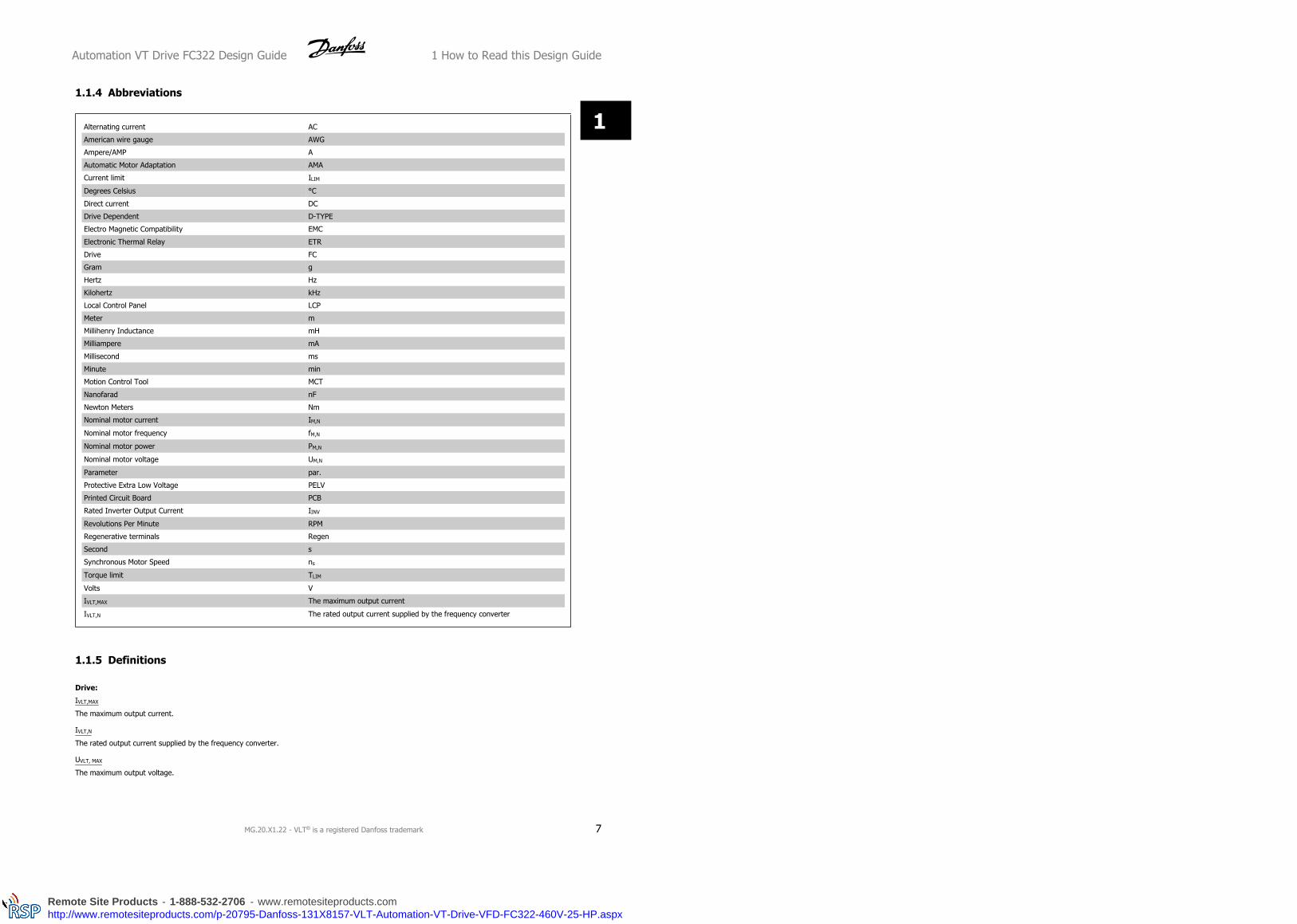
1.1.4 Abbreviations
Alternating current AC
American wire gauge AWG
Ampere/AMP A
Automatic Motor Adaptation AMA
Current limit ILIM
Degrees Celsius °C
Direct current DC
Drive Dependent D-TYPE
Electro Magnetic Compatibility EMC
Electronic Thermal Relay ETR
Drive FC
Gram g
Hertz Hz
Kilohertz kHz
Local Control Panel LCP
Meter m
Millihenry Inductance mH
Milliampere mA
Millisecond ms
Minute min
Motion Control Tool MCT
Nanofarad nF
Newton Meters Nm
Nominal motor current IM,N
Nominal motor frequency fM,N
Nominal motor power PM,N
Nominal motor voltage UM,N
Parameter par.
Protective Extra Low Voltage PELV
Printed Circuit Board PCB
Rated Inverter Output Current IINV
Revolutions Per Minute RPM
Regenerative terminals Regen
Second s
Synchronous Motor Speed ns
Torque limit TLIM
Volts V
IVLT,MAX The maximum output current
IVLT,N The rated output current supplied by the frequency converter
1.1.5 Definitions
Drive:
IVLT,MAX
The maximum output current.
IVLT,N
The rated output current supplied by the frequency converter.
UVLT, MAX
The maximum output voltage.
Automation VT Drive FC322 Design Guide 1 How to Read this Design Guide
MG.20.X1.22 - VLT® is a registered Danfoss trademark 7
1
Remote Site Products - 1-888-532-2706 - www.remotesiteproducts.comhttp://www.remotesiteproducts.com/p-20795-Danfoss-131X8157-VLT-Automation-VT-Drive-VFD-FC322-460V-25-HP.aspx

Input:
Control commandYou can start and stop the connected motor by means ofLCP and the digital inputs.Functions are divided into two groups.Functions in group 1 have higher priority than functions ingroup 2.
Group 1 Reset, Coasting stop, Reset and Coasting stop, Quick-stop, DC braking, Stop and the "Off" key.
Group 2 Start, Pulse start, Reversing, Start reversing, Jog andFreeze output
Motor:
fJOG
The motor frequency when the jog function is activated (via digital terminals).
fM
The motor frequency.
fMAX
The maximum motor frequency.
fMIN
The minimum motor frequency.
fM,N
The rated motor frequency (nameplate data).
IM
The motor current.
IM,N
The rated motor current (nameplate data).
nM,N
The rated motor speed (nameplate data).
PM,N
The rated motor power (nameplate data).
TM,N
The rated torque (motor).
UM
The instantaneous motor voltage.
UM,N
The rated motor voltage (nameplate data).
1 How to Read this Design Guide Automation VT Drive FC322 Design Guide
8 MG.20.X1.22 - VLT® is a registered Danfoss trademark
1
Remote Site Products - 1-888-532-2706 - www.remotesiteproducts.comhttp://www.remotesiteproducts.com/p-20795-Danfoss-131X8157-VLT-Automation-VT-Drive-VFD-FC322-460V-25-HP.aspx

ηVLT
The efficiency of the frequency converter is defined as the ratio between the power output and the power input.
Start-disable command
A stop command belonging to the group 1 control commands - see this group.
Stop command
See Control commands.
References:
Analog Reference
A signal transmitted to the analog inputs 53 or 54, can be voltage or current.
Bus Reference
A signal transmitted to the serial communication port (FC port).
Preset Reference
A defined preset reference to be set from -100% to +100% of the reference range. Selection of eight preset references via the digital terminals.
Pulse Reference
A pulse frequency signal transmitted to the digital inputs (terminal 29 or 33).
RefMAX
Determines the relationship between the reference input at 100% full scale value (typically 10 V, 20mA) and the resulting reference. The maximum
reference value set in par. 3-03.
RefMIN
Determines the relationship between the reference input at 0% value (typically 0V, 0mA, 4mA) and the resulting reference. The minimum reference value
set in par. 3-02.
Miscellaneous:
Analog Inputs
The analog inputs are used for controlling various functions of the frequency converter.
There are two types of analog inputs:
Current input, 0-20 mA and 4-20 mA
Voltage input, 0-10 V DC.
Analog Outputs
The analog outputs can supply a signal of 0-20 mA, 4-20 mA, or a digital signal.
Automatic Motor Adaptation, AMA
AMA algorithm determines the electrical parameters for the connected motor at standstill.
Brake Resistor
The brake resistor is a module capable of absorbing the brake power generated in regenerative braking. This regenerative braking power increases the
intermediate circuit voltage and a brake chopper ensures that the power is transmitted to the brake resistor.
CT Characteristics
Constant torque characteristics used for positive displacement pumps and blowers.
Automation VT Drive FC322 Design Guide 1 How to Read this Design Guide
MG.20.X1.22 - VLT® is a registered Danfoss trademark 9
1
Remote Site Products - 1-888-532-2706 - www.remotesiteproducts.comhttp://www.remotesiteproducts.com/p-20795-Danfoss-131X8157-VLT-Automation-VT-Drive-VFD-FC322-460V-25-HP.aspx

Digital Inputs
The digital inputs can be used for controlling various functions of the frequency converter.
1 How to Read this Design Guide Automation VT Drive FC322 Design Guide
10 MG.20.X1.22 - VLT® is a registered Danfoss trademark
1
Remote Site Products - 1-888-532-2706 - www.remotesiteproducts.comhttp://www.remotesiteproducts.com/p-20795-Danfoss-131X8157-VLT-Automation-VT-Drive-VFD-FC322-460V-25-HP.aspx

Digital Outputs
The drive features two Solid State outputs that can supply a 24 V DC (max. 40 mA) signal.
DSP
Digital Signal Processor.
Relay Outputs:
The frequency converter drive features two programmable Relay Outputs.
ETR
Electronic Thermal Relay is a thermal load calculation based on present load and time. Its purpose is to estimate the motor temperature.
GLCP:
Graphical Local Control Panel (LCP102)
Initialising
If initialising is carried out (par. 14-22), the programmable parameters of the frequency converter return to their default settings.
Intermittent Duty Cycle
An intermittent duty rating refers to a sequence of duty cycles. Each cycle consists of an on-load and an off-load period. The operation can be either
periodic duty or none-periodic duty.
LCP
The Local Control Panel (LCP) makes up a complete interface for control and programming of the frequency converter. The control panel is detachable
and can be installed up to 3 metres from the frequency converter, i.e. in a front panel by means of the installation kit option.
The Local Control Panel is available in two versions:
- Numerical LCP101 (NLCP)
- Graphical LCP102 (GLCP)
lsb
Least significant bit.
MCM
Short for Mille Circular Mil, an American measuring unit for cable cross-section. 1 MCM ≡ 0.5067 mm2.
msb
Most significant bit.
NLCP
Numerical Local Control Panel LCP101
On-line/Off-line Parameters
Changes to on-line parameters are activated immediately after the data value is changed. Changes to off-line parameters are not activated until you enter
[OK] on the LCP.
PID Controller
The PID controller maintains the desired speed, pressure, temperature, etc. by adjusting the output frequency to match the varying load.
RCD
Residual Current Device.
Automation VT Drive FC322 Design Guide 1 How to Read this Design Guide
MG.20.X1.22 - VLT® is a registered Danfoss trademark 11
1
Remote Site Products - 1-888-532-2706 - www.remotesiteproducts.comhttp://www.remotesiteproducts.com/p-20795-Danfoss-131X8157-VLT-Automation-VT-Drive-VFD-FC322-460V-25-HP.aspx

Set-up
You can save parameter settings in four Set-ups. Change between the four parameter Set-ups and edit one Set-up, while another Set-up is active.
1 How to Read this Design Guide Automation VT Drive FC322 Design Guide
12 MG.20.X1.22 - VLT® is a registered Danfoss trademark
1
Remote Site Products - 1-888-532-2706 - www.remotesiteproducts.comhttp://www.remotesiteproducts.com/p-20795-Danfoss-131X8157-VLT-Automation-VT-Drive-VFD-FC322-460V-25-HP.aspx

SFAVM
Switching pattern called S tator F lux oriented A synchronous V ector M odulation (par. 14-00).
Slip Compensation
The frequency converter compensates for the motor slip by giving the frequency a supplement that follows the measured motor load keeping the motor
speed almost constant..
Smart Logic Control (SLC)
The SLC is a sequence of user defined actions executed when the associated user defined events are evaluated as true by the SLC.
Thermistor:
A temperature-dependent resistor placed where the temperature is to be monitored (frequency converter or motor).
Trip
A state entered in fault situations, e.g. if the frequency converter is subject to an over-temperature or when the frequency converter is protecting the
motor, process or mechanism. Restart is prevented until the cause of the fault has disappeared and the trip state is cancelled by activating reset or, in
some cases, by being programmed to reset automatically. Trip may not be used for personal safety.
Trip Locked
A state entered in fault situations when the frequency converter is protecting itself and requiring physical intervention, e.g. if the frequency converter is
subject to a short circuit on the output. A locked trip can only be cancelled by cutting off mains, removing the cause of the fault, and reconnecting the
frequency converter. Restart is prevented until the trip state is cancelled by activating reset or, in some cases, by being programmed to reset automatically.
Trip locked may not be used for personal safety.
VT Characteristics
Variable torque characteristics used for pumps and fans.
VVCplus
If compared with standard voltage/frequency ratio control, Voltage Vector Control (VVCplus) improves the dynamics and the stability, both when the speed
reference is changed and in relation to the load torque.
60° AVM
Switching pattern called 60°A synchronous V ector M odulation (par. 14-00).
1.1.6 Power Factor
The power factor is the relation between I1 and IRMS.Power factor =
3 × U × I1 × COSϕ3 × U × IRMS
The power factor for 3-phase control:=
I1 × cosϕ1IRMS
=I1
IRMS since cosϕ1 = 1
The power factor indicates to which extent the frequency converter im-
poses a load on the mains supply.
The lower the power factor, the higher the IRMS for the same kW per-
formance.
IRMS = I12 + I5
2 + I72 + . . + In
2
In addition, a high power factor indicates that the different harmonic currents are low.
The frequency converters' built-in DC coils produce a high power factor, which minimizes the imposed load on the mains supply.
Automation VT Drive FC322 Design Guide 1 How to Read this Design Guide
MG.20.X1.22 - VLT® is a registered Danfoss trademark 13
1
Remote Site Products - 1-888-532-2706 - www.remotesiteproducts.comhttp://www.remotesiteproducts.com/p-20795-Danfoss-131X8157-VLT-Automation-VT-Drive-VFD-FC322-460V-25-HP.aspx

2 Introduction to VLT Automation VT Drive Automation VT Drive FC322 Design Guide
14 MG.20.X1.22 - VLT® is a registered Danfoss trademark
2
Remote Site Products - 1-888-532-2706 - www.remotesiteproducts.comhttp://www.remotesiteproducts.com/p-20795-Danfoss-131X8157-VLT-Automation-VT-Drive-VFD-FC322-460V-25-HP.aspx

2 Introduction to VLT Automation VT Drive
2.1 Safety
2.1.1 Safety Note
The voltage of the frequency converter is dangerous whenever connected to mains. Incorrect installation of the motor, frequency
converter or fieldbus may cause damage to the equipment, serious personal injury or death. Consequently, the instructions in this
manual, as well as national and local rules and safety regulations, must be complied with.
Safety Regulations
1. The frequency converter must be disconnected from mains if repair work is to be carried out. Check that the mains supply has been disconnected and
that the necessary time has passed before removing motor and mains plugs.
2. The [STOP/RESET] key on the control panel of the frequency converter does not disconnect the equipment from mains and is thus not to be used as
a safety switch.
3. Correct protective earthing of the equipment must be established, the user must be protected against supply voltage, and the motor must be protected
against overload in accordance with applicable national and local regulations.
4. The earth leakage currents are higher than 3.5 mA.
5. Protection against motor overload is set by par. 1-90 Motor Thermal Protection. If this function is desired, set par. 1-90 to data value [ETR trip] (default
value) or data value [ETR warning]. Note: The function is initialised at 1.16 x rated motor current and rated motor frequency. For the North American
market: The ETR functions provide class 20 motor overload protection in accordance with NEC.
6. Do not remove the plugs for the motor and mains supply while the frequency converter is connected to mains. Check that the mains supply has been
disconnected and that the necessary time has passed before removing motor and mains plugs.
7. Please note that the frequency converter has more voltage inputs than L1, L2 and L3, when load sharing (linking of DC intermediate circuit) and external
24 V DC have been installed. Check that all voltage inputs have been disconnected and that the necessary time has passed before commencing repair
work.
Installation at High Altitudes
By altitudes above 2 km, please contact Danfoss regarding PELV.
Warning against Unintended Start
1. The motor can be brought to a stop by means of digital commands, bus commands, references or a local stop, while the frequency converter is
connected to mains. If personal safety considerations make it necessary to ensure that no unintended start occurs, these stop functions are not sufficient.
2. While parameters are being changed, the motor may start. Consequently, the stop key [STOP/RESET] must always be activated; following which data
can be modified. 3. A motor that has been stopped may start if faults occur in the electronics of the frequency converter, or if a temporary overload or
a fault in the supply mains or the motor connection ceases.
Warning:
Touching the electrical parts may be fatal - even after the equipment has been disconnected from mains.
Also make sure that other voltage inputs have been disconnected, such as external 24 V DC, load sharing (linkage of DC intermediate circuit), as well as
the motor connection for kinetic back up.
Refer to VLT® Automation VT Drive FC322 Instruction Manual MG.20.UX.YY for further safety guidelines.
Automation VT Drive FC322 Design Guide 2 Introduction to VLT Automation VT Drive
MG.20.X1.22 - VLT® is a registered Danfoss trademark 15
2
Remote Site Products - 1-888-532-2706 - www.remotesiteproducts.comhttp://www.remotesiteproducts.com/p-20795-Danfoss-131X8157-VLT-Automation-VT-Drive-VFD-FC322-460V-25-HP.aspx

2.1.2 Caution
The frequency converter DC link capacitors remain charged after power has been disconnected. To avoid an electrical shock hazard,
disconnect the frequency converter from the mains before carrying out maintenance. Wait at least as follows before doing service on
the frequency converter:
Voltage (V) Min. Waiting Time (Minutes)
4 15 20 30 40
200 - 240 0.25 - 3.7 kW 5.5 - 45 kW
380 - 480 0.37 - 7.5 kW 11 - 90 kW 110 - 250 kW 315 - 1000 kW
525-600 0.75 kW - 7.5 kW 11 - 90 kW 315 - 1200 kW
525-690 11 - 90 kW 45 - 400 kW 450 - 1200 kW
Be aware that there may be high voltage on the DC link even when the LEDs are turned off.
2.1.3 Disposal Instruction
Equipment containing electrical components may not be disposed of together with domestic
waste.
It must be separately collected with electrical and electronic waste according to local and cur-
rently valid legislation.
2.2 Software Version
2.2.1 Software Version and Approvals
VLT Automation VT Drive FC322
Software version: 1.7x
This manual can be used with all VLT Automation VT Drive FC322 frequency converters with software version 1.7x.
The software version number can be found in parameter 15-43.
2 Introduction to VLT Automation VT Drive Automation VT Drive FC322 Design Guide
16 MG.20.X1.22 - VLT® is a registered Danfoss trademark
2
Remote Site Products - 1-888-532-2706 - www.remotesiteproducts.comhttp://www.remotesiteproducts.com/p-20795-Danfoss-131X8157-VLT-Automation-VT-Drive-VFD-FC322-460V-25-HP.aspx
2.3 CE labelling
2.3.1 CE Conformity and Labelling
What is CE Conformity and Labelling?
The purpose of CE labelling is to avoid technical trade obstacles within EFTA and the EU. The EU has introduced the CE label as a simple way of showing
whether a product complies with the relevant EU directives. The CE label says nothing about the specifications or quality of the product. Frequency
converters are regulated by three EU directives:
The machinery directive (98/37/EEC)
All machines with critical moving parts are covered by the machinery directive of January 1, 1995. Since a frequency converter is largely electrical, it does
not fall under the machinery directive. However, if a frequency converter is supplied for use in a machine, we provide information on safety aspects
relating to the frequency converter. We do this by means of a manufacturer's declaration.
The low-voltage directive (73/23/EEC)
Frequency converters must be CE labelled in accordance with the low-voltage directive of January 1, 1997. The directive applies to all electrical equipment
and appliances used in the 50 - 1000 V AC and the 75 - 1500 V DC voltage ranges. Danfoss CE-labels in accordance with the directive and issues a
declaration of conformity upon request.
The EMC directive (89/336/EEC)
EMC is short for electromagnetic compatibility. The presence of electromagnetic compatibility means that the mutual interference between different
components/appliances does not affect the way the appliances work.
The EMC directive came into effect January 1, 1996. Danfoss CE-labels in accordance with the directive and issues a declaration of conformity upon
request. To carry out EMC-correct installation, see the instructions in this Design Guide. In addition, we specify which standards our products comply
with. We offer the filters presented in the specifications and provide other types of assistance to ensure the optimum EMC result.
The frequency converter is most often used by professionals of the trade as a complex component forming part of a larger appliance, system or installation.
It must be noted that the responsibility for the final EMC properties of the appliance, system or installation rests with the installer.
2.3.2 What Is Covered
The EU "Guidelines on the Application of Council Directive 89/336/EEC" outline three typical situations of using a frequency converter. See below for EMC
coverage and CE labelling.
1. The frequency converter is sold directly to the end-consumer. The frequency converter is for example sold to a DIY market. The end-consumer
is a layman. He installs the frequency converter himself for use with a hobby machine, a kitchen appliance, etc. For such applications, the
frequency converter must be CE labelled in accordance with the EMC directive.
2. The frequency converter is sold for installation in a plant. The plant is built up by professionals of the trade. It could be a production plant or a
heating/ventilation plant designed and installed by professionals of the trade. Neither the frequency converter nor the finished plant has to be
CE labelled under the EMC directive. However, the unit must comply with the basic EMC requirements of the directive. This is ensured by using
components, appliances, and systems that are CE labelled under the EMC directive.
3. The frequency converter is sold as part of a complete system. The system is being marketed as complete and could e.g. be an air-conditioning
system. The complete system must be CE labelled in accordance with the EMC directive. The manufacturer can ensure CE labelling under the
EMC directive either by using CE labelled components or by testing the EMC of the system. If he chooses to use only CE labelled components,
he does not have to test the entire system.
Automation VT Drive FC322 Design Guide 2 Introduction to VLT Automation VT Drive
MG.20.X1.22 - VLT® is a registered Danfoss trademark 17
2
Remote Site Products - 1-888-532-2706 - www.remotesiteproducts.comhttp://www.remotesiteproducts.com/p-20795-Danfoss-131X8157-VLT-Automation-VT-Drive-VFD-FC322-460V-25-HP.aspx

2.3.3 Danfoss Frequency Converter and CE Labelling
CE labelling is a positive feature when used for its original purpose, i.e. to facilitate trade within the EU and EFTA.
However, CE labelling may cover many different specifications. Thus, you have to check what a given CE label specifically covers.
The covered specifications can be very different and a CE label may therefore give the installer a false feeling of security when using a frequency converter
as a component in a system or an appliance.
Danfoss CE labels the frequency converters in accordance with the low-voltage directive. This means that if the frequency converter is installed correctly,
we guarantee compliance with the low-voltage directive. Danfoss issues a declaration of conformity that confirms our CE labelling in accordance with the
low-voltage directive.
The CE label also applies to the EMC directive provided that the instructions for EMC-correct installation and filtering are followed. On this basis, a
declaration of conformity in accordance with the EMC directive is issued.
The Design Guide offers detailed instructions for installation to ensure EMC-correct installation. Furthermore, Danfoss specifies which our different prod-
ucts comply with.
Danfoss gladly provides other types of assistance that can help you obtain the best EMC result.
2.3.4 Compliance with EMC Directive 89/336/EEC
As mentioned, the frequency converter is mostly used by professionals of the trade as a complex component forming part of a larger appliance, system,
or installation. It must be noted that the responsibility for the final EMC properties of the appliance, system or installation rests with the installer. As an
aid to the installer, Danfoss has prepared EMC installation guidelines for the Power Drive system. The standards and test levels stated for Power Drive
systems are complied with, provided that the EMC-correct instructions for installation are followed, see the section EMC Immunity.
The frequency converter has been designed to meet the IEC/EN 60068-2-3 standard, EN 50178 pkt. 9.4.2.2 at 50°C.
A frequency converter contains a large number of mechanical and electronic components. All are to some extent vulnerable to environmental effects.
The frequency converter should not be installed in environments with airborne liquids, particles, or gases capable of affecting and
damaging the electronic components. Failure to take the necessary protective measures increases the risk of stoppages, thus reducing
the life of the frequency converter.
Liquids can be carried through the air and condense in the frequency converter and may cause corrosion of components and metal parts. Steam, oil, and
salt water may cause corrosion of components and metal parts. In such environments, use equipment with enclosure rating IP 54/55. As an extra
protection, coated printed circuit boards can be ordered as an option.
Airborne Particles such as dust may cause mechanical, electrical, or thermal failure in the frequency converter. A typical indicator of excessive levels of
airborne particles is dust particles around the frequency converter fan. In very dusty environments, use equipment with enclosure rating IP 54/55 or a
cabinet for IP 00/IP 20/TYPE 1 equipment.
In environments with high temperatures and humidity, corrosive gases such as sulphur, nitrogen, and chlorine compounds will cause chemical processes
on the frequency converter components.
2 Introduction to VLT Automation VT Drive Automation VT Drive FC322 Design Guide
18 MG.20.X1.22 - VLT® is a registered Danfoss trademark
2
Remote Site Products - 1-888-532-2706 - www.remotesiteproducts.comhttp://www.remotesiteproducts.com/p-20795-Danfoss-131X8157-VLT-Automation-VT-Drive-VFD-FC322-460V-25-HP.aspx

Such chemical reactions will rapidly affect and damage the electronic components. In such environments, mount the equipment in a cabinet with fresh
air ventilation, keeping aggressive gases away from the frequency converter.
An extra protection in such areas is a coating of the printed circuit boards, which can be ordered as an option.
NB!
Mounting frequency converters in aggressive environments increases the risk of stoppages and considerably reduces the life of the
converter.
Before installing the frequency converter, check the ambient air for liquids, particles, and gases. This is done by observing existing installations in this
environment. Typical indicators of harmful airborne liquids are water or oil on metal parts, or corrosion of metal parts.
Excessive dust particle levels are often found on installation cabinets and existing electrical installations. One indicator of aggressive airborne gases is
blackening of copper rails and cable ends on existing installations.
NB!
D and E enclosures have a stainless steel back-channel option to provide additional protection in aggressive environments. Proper ventilation is still
required for the internal components of the drive. Contact Danfoss for additional information.
2.4 Vibration and shockThe frequency converter has been tested according to the procedure based on the shown standards:
The frequency converter complies with requirements that exist for units mounted on the walls and floors of production premises, as well as in panels
bolted to walls or floors.
IEC/EN 60068-2-6: Vibration (sinusoidal) - 1970
IEC/EN 60068-2-64: Vibration, broad-band random
2.5 Advantages
2.7.1 Why use a Frequency Converter for Controlling Fans and Pumps?
A frequency converter takes advantage of the fact that centrifugal fans and pumps follow the laws of proportionality for such fans and pumps. For further
information see the text The Laws of Proportionality.
2.7.2 The Clear Advantage - Energy Savings
The very clear advantage of using a frequency converter for controlling the speed of fans or pumps lies in the electricity savings.
When comparing with alternative control systems and technologies, a frequency converter is the optimum energy control system for controlling fan and
pump systems.
Automation VT Drive FC322 Design Guide 2 Introduction to VLT Automation VT Drive
MG.20.X1.22 - VLT® is a registered Danfoss trademark 19
2
Remote Site Products - 1-888-532-2706 - www.remotesiteproducts.comhttp://www.remotesiteproducts.com/p-20795-Danfoss-131X8157-VLT-Automation-VT-Drive-VFD-FC322-460V-25-HP.aspx

Illustration 2.1: The graph is showing fan curves (A, B and
C) for reduced fan volumes.
Illustration 2.2: When using a frequency converter to reduce
fan capacity to 60% - more than 50% energy savings may
be obtained in typical applications.
2.7.3 Example of Energy Savings
As can be seen from the figure (the laws of proportionality), the flow is controlled by changing the RPM. By reducing the speed only 20% from the rated
speed, the flow is also reduced by 20%. This is because the flow is directly proportional to the RPM. The consumption of electricity, however, is reduced
by 50%.
If the system in question only needs to be able to supply a flow that corresponds to 100% a few days in a year, while the average is below 80% of the
rated flow for the remainder of the year, the amount of energy saved is even more than 50%.
The laws of proportionality
The figure below describes the dependence of flow, pressure and power consumption on RPM.
Q = Flow P = Power
Q1 = Rated flow P1 = Rated power
Q2 = Reduced flow P2 = Reduced power
H = Pressure n = Speed regulation
H1 = Rated pressure n1 = Rated speed
H2 = Reduced pressure n2 = Reduced speed
2 Introduction to VLT Automation VT Drive Automation VT Drive FC322 Design Guide
20 MG.20.X1.22 - VLT® is a registered Danfoss trademark
2
Remote Site Products - 1-888-532-2706 - www.remotesiteproducts.comhttp://www.remotesiteproducts.com/p-20795-Danfoss-131X8157-VLT-Automation-VT-Drive-VFD-FC322-460V-25-HP.aspx

Flow :Q1Q2
= n1n2
Pressure :H1H2
= ( n1n2 )2
Power :P1P2
= ( n1n2 )3
2.7.4 Example with Varying Flow over 1 Year
The example below is calculated on the basis of pump characteristics ob-
tained from a pump datasheet.
The result obtained shows energy savings in excess of 50% at the given
flow distribution over a year. The pay back period depends on the price
per kwh and price of frequency converter. In this example it is less than
a year when compared with valves and constant speed.
Energy savings
Pshaft=Pshaft output
Flow distribution over 1 year
Automation VT Drive FC322 Design Guide 2 Introduction to VLT Automation VT Drive
MG.20.X1.22 - VLT® is a registered Danfoss trademark 21
2
Remote Site Products - 1-888-532-2706 - www.remotesiteproducts.comhttp://www.remotesiteproducts.com/p-20795-Danfoss-131X8157-VLT-Automation-VT-Drive-VFD-FC322-460V-25-HP.aspx

m3/h Distribution Valve regulation Frequency converter control
% Hours Power Consumption Power Consumption
A1 - B1 kWh A1 - C1 kWh
350 5 438 42,5 18.615 42,5 18.615
300 15 1314 38,5 50.589 29,0 38.106
250 20 1752 35,0 61.320 18,5 32.412
200 20 1752 31,5 55.188 11,5 20.148
150 20 1752 28,0 49.056 6,5 11.388
100 20 1752 23,0 40.296 3,5 6.132
Σ 100 8760 275.064 26.801
2.7.5 Better Control
If a frequency converter is used for controlling the flow or pressure of a system, improved control is obtained.
A frequency converter can vary the speed of the fan or pump, thereby obtaining variable control of flow and pressure.
Furthermore, a frequency converter can quickly adapt the speed of the fan or pump to new flow or pressure conditions in the system.
Simple control of process (Flow, Level or Pressure) utilizing the built in PID control.
2.7.6 Cos φ Compensation
Generally speaking, a frequency converter with a cos φ of 1 provides power factor correction for the cos φ of the motor, which means that there is no
need to make allowance for the cos φ of the motor when sizing the power factor correction unit.
2 Introduction to VLT Automation VT Drive Automation VT Drive FC322 Design Guide
22 MG.20.X1.22 - VLT® is a registered Danfoss trademark
2
Remote Site Products - 1-888-532-2706 - www.remotesiteproducts.comhttp://www.remotesiteproducts.com/p-20795-Danfoss-131X8157-VLT-Automation-VT-Drive-VFD-FC322-460V-25-HP.aspx

2.7.7 Star/delta Starter or Soft-starter not required
When larger motors are started, it is necessary in many countries to use equipment that limits the start-up current. In more traditional systems, a star/
delta starter or soft-starter is widely used. Such motor starters are not required if a frequency converter is used.
As illustrated in the figure below, a frequency converter does not consume more than rated current.
1 = VLT Automation VT Drive
2 = Star/delta starter
3 = Soft-starter
4 = Start directly on mains
Automation VT Drive FC322 Design Guide 2 Introduction to VLT Automation VT Drive
MG.20.X1.22 - VLT® is a registered Danfoss trademark 23
2
Remote Site Products - 1-888-532-2706 - www.remotesiteproducts.comhttp://www.remotesiteproducts.com/p-20795-Danfoss-131X8157-VLT-Automation-VT-Drive-VFD-FC322-460V-25-HP.aspx
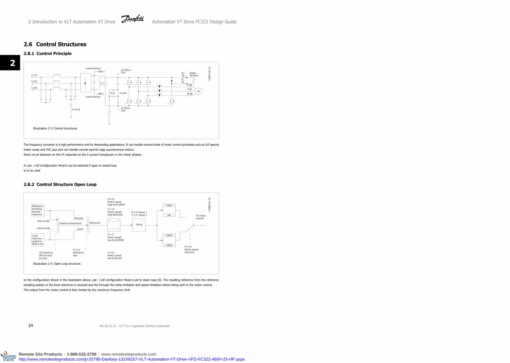
2.6 Control Structures
2.8.1 Control Principle
Illustration 2.3: Control structures.
The frequency converter is a high performance unit for demanding applications. It can handle various kinds of motor control principles such as U/f special
motor mode and VVC plus and can handle normal squirrel cage asynchronous motors.
Short circuit behavior on this FC depends on the 3 current transducers in the motor phases.
In par. 1-00 Configuration Mode it can be selected if open or closed loop
is to be used
2.8.2 Control Structure Open Loop
Illustration 2.4: Open Loop structure.
In the configuration shown in the illustration above, par. 1-00 Configuration Mode is set to Open loop [0]. The resulting reference from the reference
handling system or the local reference is received and fed through the ramp limitation and speed limitation before being sent to the motor control.
The output from the motor control is then limited by the maximum frequency limit.
2 Introduction to VLT Automation VT Drive Automation VT Drive FC322 Design Guide
24 MG.20.X1.22 - VLT® is a registered Danfoss trademark
2
Remote Site Products - 1-888-532-2706 - www.remotesiteproducts.comhttp://www.remotesiteproducts.com/p-20795-Danfoss-131X8157-VLT-Automation-VT-Drive-VFD-FC322-460V-25-HP.aspx

2.8.3 Local (Hand On) and Remote (Auto On) Control
The frequency converter can be operated manually via the local control panel (LCP) or remotely via analog/digital inputs or serial bus.
If allowed in par. 0-40 [Hand on] Key on LCP, par. 0-41 [Off] Key on LCP, par. 0-42 [Auto on] Key on LCP, and par. 0-43 [Reset] Key on LCP, it is possible
to start and stop the frequency converter byLCP using the [Hand ON] and [Off] keys. Alarms can be reset via the [RESET] key. After pressing the [Hand
On] key, the frequency converter goes into Hand Mode and follows (as default) the Local reference set by using the LCP arrow keys up [] and down
[].
After pressing the [Auto On] key, the frequency converter goes into Auto
mode and follows (as default) the Remote reference. In this mode, it is
possible to control the frequency converter via the digital inputs and var-
ious serial interfaces (RS-485, USB, or an optional fieldbus). See more
about starting, stopping, changing ramps and parameter set-ups etc. in
par. group 5-1* (digital inputs) or par. group 8-5* (serial communica-
tion).130BP046.10
Hand Off
Auto
LCP Keys
Reference Site
par. 3-13 Reference Site
Active Reference
Hand Linked to Hand / Auto Local
Hand -> Off Linked to Hand / Auto Local
Auto Linked to Hand / Auto Remote
Auto -> Off Linked to Hand / Auto Remote
All keys Local Local
All keys Remote Remote
The table shows under which conditions either the Local Reference or the Remote Reference is active. One of them is always active, but both can not be
active at the same time.
NB!
Local Reference will be restored at power-down.
par. 1-00 Configuration Mode determines what kind of application control principle (i.e. Open Loop or Closed loop) is used when the Remote reference
is active (see table above for the conditions).
Automation VT Drive FC322 Design Guide 2 Introduction to VLT Automation VT Drive
MG.20.X1.22 - VLT® is a registered Danfoss trademark 25
2
Remote Site Products - 1-888-532-2706 - www.remotesiteproducts.comhttp://www.remotesiteproducts.com/p-20795-Danfoss-131X8157-VLT-Automation-VT-Drive-VFD-FC322-460V-25-HP.aspx

2.8.4 Control Structure Closed Loop
The closed loop controller allows the drive to become an integral part of the controlled system. The drive receives a feedback signal from a sensor in the
system. It then compares this feedback to a set-point reference value and determines the error, if any, between these two signals. It then adjusts the
speed of the motor to correct this error.
For example, consider a pump application where the speed of a pump is to be controlled so that the static pressure in a pipe is constant. The desired
static pressure value is supplied to the drive as the set-point reference. A static pressure sensor measures the actual static pressure in the pipe and
supplies this to the drive as a feedback signal. If the feedback signal is greater than the set-point reference, the drive will slow down to reduce the
pressure. In a similar way, if the pipe pressure is lower than the set-point reference, the drive will automatically speed up to increase the pressure provided
by the pump.
NB!
While the default values for the drive’s Closed Loop controller will often provide satisfactory performance, the control of the system
can often be optimized by adjusting some of the Closed Loop controller’s parameters. It is also possible to autotune the PI constants.
The figure is a block diagram of the drive’s Closed Loop controller. The details of the Reference Handling block and Feedback Handling block are described
in their respective sections below.
2 Introduction to VLT Automation VT Drive Automation VT Drive FC322 Design Guide
26 MG.20.X1.22 - VLT® is a registered Danfoss trademark
2
Remote Site Products - 1-888-532-2706 - www.remotesiteproducts.comhttp://www.remotesiteproducts.com/p-20795-Danfoss-131X8157-VLT-Automation-VT-Drive-VFD-FC322-460V-25-HP.aspx

2.8.5 Feedback Handling
A block diagram of how the drive processes the feedback signal is shown below.
Feedback handling can be configured to work with applications requiring advanced control, such as multiple setpoints and multiple feedbacks. Three
types of control are common.
Single Zone, Single Setpoint
Single Zone Single Setpoint is a basic configuration. Setpoint 1 is added to any other reference (if any, see Reference Handling) and the feedback signal
is selected using par. 20-20.
Multi Zone, Single Setpoint
Multi Zone Single Setpoint uses two or three feedback sensors but only one setpoint. The feedbacks can be added, subtracted (only feedback 1 and 2)
or averaged. In addition, the maximum or minimum value may be used. Setpoint 1 is used exclusively in this configuration.
If Multi Setpoint Min [13] is selected, the setpoint/feedback pair with the largest difference controls the speed of the drive. Multi Setpoint Maximum [14]
attempts to keep all zones at or below their respective setpoints, while Multi Setpoint Min [13] attempts to keep all zones at or above their respective
setpoints.
Example:
A two zone two setpoint application Zone 1 setpoint is 15 bar and the feedback is 5.5 bar. Zone 2 setpoint is 4.4 bar and the feedback is 4.6 bar. If Multi
Setpoint Max [14] is selected, Zone 1’s setpoint and feedback are sent to the PID controller, since this has the smaller difference (feedback is higher than
setpoint, resulting in a negative difference). If Multi Setpoint Min [13] is selected, Zone 2’s setpoint and feedback is sent to the PID controller, since this
has the larger difference (feedback is lower than setpoint, resulting in a positive difference).
Automation VT Drive FC322 Design Guide 2 Introduction to VLT Automation VT Drive
MG.20.X1.22 - VLT® is a registered Danfoss trademark 27
2
Remote Site Products - 1-888-532-2706 - www.remotesiteproducts.comhttp://www.remotesiteproducts.com/p-20795-Danfoss-131X8157-VLT-Automation-VT-Drive-VFD-FC322-460V-25-HP.aspx

2.8.6 Feedback Conversion
In some applications it may be useful to convert the feedback signal. One example of this is using a pressure signal to provide flow feedback. Since the
square root of pressure is proportional to flow, the square root of the pressure signal yields a value proportional to the flow. This is shown below.
2.8.7 Reference Handling
Details for Open Loop and Closed Loop operation.
A block diagram of how the drive produces the Remote Reference is shown below:.
2 Introduction to VLT Automation VT Drive Automation VT Drive FC322 Design Guide
28 MG.20.X1.22 - VLT® is a registered Danfoss trademark
2
Remote Site Products - 1-888-532-2706 - www.remotesiteproducts.comhttp://www.remotesiteproducts.com/p-20795-Danfoss-131X8157-VLT-Automation-VT-Drive-VFD-FC322-460V-25-HP.aspx

Automation VT Drive FC322 Design Guide 2 Introduction to VLT Automation VT Drive
MG.20.X1.22 - VLT® is a registered Danfoss trademark 29
2
Remote Site Products - 1-888-532-2706 - www.remotesiteproducts.comhttp://www.remotesiteproducts.com/p-20795-Danfoss-131X8157-VLT-Automation-VT-Drive-VFD-FC322-460V-25-HP.aspx

The Remote Reference is comprised of:
• Preset references.
• External references (analog inputs, pulse frequency inputs, digital potentiometer inputs and serial communication bus references).
• The Preset relative reference.
• Feedback controlled setpoint.
Up to 8 preset references can be programmed in the drive. The active preset reference can be selected using digital inputs or the serial communications
bus. The reference can also be supplied externally, most commonly from an analog input. This external source is selected by one of the 3 Reference
Source parameters (par. 3-15 Reference 1 Source, par. 3-16 Reference 2 Source and par. 3-17 Reference 3 Source). Digipot is a digital potentiometer.
This is also commonly called a Speed Up/Speed Down Control or a Floating Point Control. To set it up, one digital input is programmed to increase the
reference while another digital input is programmed to decrease the reference. A third digital input can be used to reset the Digipot reference. All reference
resources and the bus reference are added to produce the total External Reference. The External Reference, the Preset Reference or the sum of the two
can be selected to be the active reference. Finally, this reference can by be scaled using par. 3-14 Preset Relative Reference.
The scaled reference is calculated as follows:
Reference = X + X × ( Y100 )
Where X is the external reference, the preset reference or the sum of these and Y is par. 3-14 Preset Relative Reference in [%].
NB!
If Y, par. 3-14 Preset Relative Reference is set to 0%, the reference will not be affected by the scaling
2 Introduction to VLT Automation VT Drive Automation VT Drive FC322 Design Guide
30 MG.20.X1.22 - VLT® is a registered Danfoss trademark
2
Remote Site Products - 1-888-532-2706 - www.remotesiteproducts.comhttp://www.remotesiteproducts.com/p-20795-Danfoss-131X8157-VLT-Automation-VT-Drive-VFD-FC322-460V-25-HP.aspx

2.8.8 Example of Closed Loop PID Control
The following is an example of a Closed Loop Control for a booster pump application:
In a water distribution system, the pressure is to be maintained at a constant value. The desired pressure (setpoint) is set between 0 and 10 Bar using
a 0-10 volt potentiometer or can be set by a parameter. The pressure sensor has a range of 0 to 10 Bar and uses a two-wire transmitter to provide a
4-20 mA signal. The output frequency range of the drive is 10 to 50 Hz.
1. Start/Stop via switch connected between terminals 12 (+24 V) and 18.
2. Pressure reference via a potentiometer (0-10 Bar, 0-10 V) connected
to terminals 50 (+10 V), 53 (input) and 55 (common).
3. Pressure feedback via transmitter (0-10 Bar, 4-20 mA) connected to
terminal 54. Switch S202 behind the Local Control Panel set to ON
(current input).
Automation VT Drive FC322 Design Guide 2 Introduction to VLT Automation VT Drive
MG.20.X1.22 - VLT® is a registered Danfoss trademark 31
2
Remote Site Products - 1-888-532-2706 - www.remotesiteproducts.comhttp://www.remotesiteproducts.com/p-20795-Danfoss-131X8157-VLT-Automation-VT-Drive-VFD-FC322-460V-25-HP.aspx
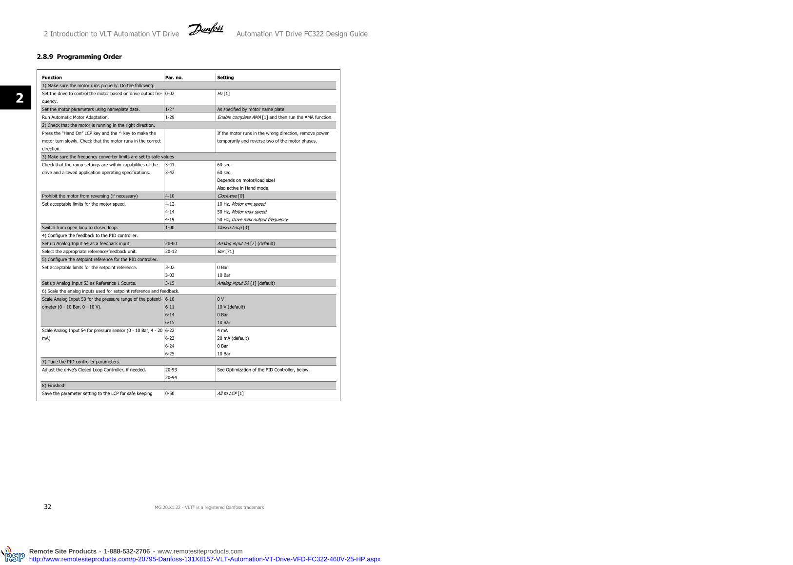
2.8.9 Programming Order
Function Par. no. Setting
1) Make sure the motor runs properly. Do the following:
Set the drive to control the motor based on drive output fre-
quency.
0-02 Hz [1]
Set the motor parameters using nameplate data. 1-2* As specified by motor name plate
Run Automatic Motor Adaptation. 1-29 Enable complete AMA [1] and then run the AMA function.
2) Check that the motor is running in the right direction.
Press the “Hand On” LCP key and the ^ key to make the
motor turn slowly. Check that the motor runs in the correct
direction.
If the motor runs in the wrong direction, remove power
temporarily and reverse two of the motor phases.
3) Make sure the frequency converter limits are set to safe values
Check that the ramp settings are within capabilities of the
drive and allowed application operating specifications.
3-41
3-42
60 sec.
60 sec.
Depends on motor/load size!
Also active in Hand mode.
Prohibit the motor from reversing (if necessary) 4-10 Clockwise [0]
Set acceptable limits for the motor speed. 4-12
4-14
4-19
10 Hz, Motor min speed
50 Hz, Motor max speed
50 Hz, Drive max output frequency
Switch from open loop to closed loop. 1-00 Closed Loop [3]
4) Configure the feedback to the PID controller.
Set up Analog Input 54 as a feedback input. 20-00 Analog input 54 [2] (default)
Select the appropriate reference/feedback unit. 20-12 Bar [71]
5) Configure the setpoint reference for the PID controller.
Set acceptable limits for the setpoint reference. 3-02
3-03
0 Bar
10 Bar
Set up Analog Input 53 as Reference 1 Source. 3-15 Analog input 53 [1] (default)
6) Scale the analog inputs used for setpoint reference and feedback.
Scale Analog Input 53 for the pressure range of the potenti-
ometer (0 - 10 Bar, 0 - 10 V).
6-10
6-11
6-14
6-15
0 V
10 V (default)
0 Bar
10 Bar
Scale Analog Input 54 for pressure sensor (0 - 10 Bar, 4 - 20
mA)
6-22
6-23
6-24
6-25
4 mA
20 mA (default)
0 Bar
10 Bar
7) Tune the PID controller parameters.
Adjust the drive’s Closed Loop Controller, if needed. 20-93
20-94
See Optimization of the PID Controller, below.
8) Finished!
Save the parameter setting to the LCP for safe keeping 0-50 All to LCP [1]
2 Introduction to VLT Automation VT Drive Automation VT Drive FC322 Design Guide
32 MG.20.X1.22 - VLT® is a registered Danfoss trademark
2
Remote Site Products - 1-888-532-2706 - www.remotesiteproducts.comhttp://www.remotesiteproducts.com/p-20795-Danfoss-131X8157-VLT-Automation-VT-Drive-VFD-FC322-460V-25-HP.aspx
2.8.10 Tuning the Drive Closed Loop Controller
Once the drive’s Closed Loop Controller has been set up, the performance of the controller should be tested. In many cases, its performance may be
acceptable using the default values of PID Proportional Gain (par. 20-93) and PID Integral Time (par. 20-94). However, in some cases it may be helpful
to optimize these parameter values to provide faster system response while still controlling speed overshoot.
2.8.11 Manual PID Adjustment
1. Start the motor
2. Set par. 20-93 (PID Proportional Gain) to 0.3 and increase it until the feedback signal begins to oscillate. If necessary, start and stop the drive
or make step changes in the set-point reference to attempt to cause oscillation. Next reduce the PID Proportional Gain until the feedback signal
stabilizes. Then reduce the proportional gain by 40-60%.
3. Set par. 20-94 (PID Integral Time) to 20 sec. and reduce it until the feedback signal begins to oscillate. If necessary, start and stop the drive
or make step changes in the set-point reference to attempt to cause oscillation. Next, increase the PID Integral Time until the feedback signal
stabilizes. Then increase of the Integral Time by 15-50%.
4. Par. 20-95 (PID Differential Time) should only be used for very fast-acting systems. The typical value is 25% of the PID Integral Time (par.
20-94). The differential function should only be used when the setting of the proportional gain and the integral time has been fully optimized.
Make sure that oscillations of the feedback signal are sufficiently dampened by the low-pass filter for the feedback signal (par 6 16, 6 26, 5 54
or 5 59, as required).
Automation VT Drive FC322 Design Guide 2 Introduction to VLT Automation VT Drive
MG.20.X1.22 - VLT® is a registered Danfoss trademark 33
2
Remote Site Products - 1-888-532-2706 - www.remotesiteproducts.comhttp://www.remotesiteproducts.com/p-20795-Danfoss-131X8157-VLT-Automation-VT-Drive-VFD-FC322-460V-25-HP.aspx

2.7 General aspects of EMC
2.9.1 General Aspects of EMC Emissions
Electrical interference is usually conducted at frequences in the range 150 kHz to 30 MHz. Airborne interference from the drive system in the range 30
MHz to 1 GHz is generated from the inverter, motor cable, and the motor.
As shown in the illustration below, capacitive currents in the motor cable coupled with a high dV/dt from the motor voltage generate leakage currents.
The use of a screened motor cable increases the leakage current (see illustration below) because screened cables have higher capacitance to earth than
unscreened cables. If the leakage current is not filtered, it will cause greater interference on the mains in the radio frequency range below approx. 5
MHz. Since the leakage current (I1) is carried back to the unit through the screen (I 3), there will in principle only be a small electro-magnetic field (I4)
from the screened motor cable according to the below figure.
The screen reduces the radiated interference but increases the low-frequency interference on the mains. The motor cable screen must be connected to
the frequency converter enclosure as well as on the motor enclosure. This is best done by using integrated screen clamps so as to avoid twisted screen
ends (pigtails). These increase the screen impedance at higher frequencies, which reduces the screen effect and increases the leakage current (I4).
If a screened cable is used for Fieldbus, relay, control cable, signal interface and brake, the screen must be mounted on the enclosure at both ends. In
some situations, however, it will be necessary to break the screen to avoid current loops.
If the screen is to be placed on a mounting plate for the frequency converter, the mounting plate must be made of metal, because the screen currents
have to be conveyed back to the unit. Moreover, ensure good electrical contact from the mounting plate through the mounting screws to the frequency
converter chassis.
NB!
When unscreened cables are used, some emission requirements are not complied with, although the immunity requirements are ob-
served.
In order to reduce the interference level from the entire system (unit + installation), make motor and brake cables as short as possible. Avoid placing
cables with a sensitive signal level alongside motor and brake cables. Radio interference higher than 50 MHz (airborne) is especially generated by the
control electronics.
2 Introduction to VLT Automation VT Drive Automation VT Drive FC322 Design Guide
34 MG.20.X1.22 - VLT® is a registered Danfoss trademark
2
Remote Site Products - 1-888-532-2706 - www.remotesiteproducts.comhttp://www.remotesiteproducts.com/p-20795-Danfoss-131X8157-VLT-Automation-VT-Drive-VFD-FC322-460V-25-HP.aspx

2.9.2 Emission Requirements
According to the EMC product standard for adjustable speed frequency converters EN/IEC61800-3:2004 the EMC requirements depend on the intended
use of the frequency converter. Four categories are defined in the EMC product standard. The definitions of the four categories together with the
requirements for mains supply voltage conducted emissions are given in the table below:
Category Definition
Conducted emission requirement
according to the limits given in
EN55011
C1 frequency converters installed in the first environment (home and office) with a supply
voltage less than 1000 V.
Class B
C2 frequency converters installed in the first environment (home and office) with a supply
voltage less than 1000 V, which are neither plug-in nor movable and are intended to be
installed and commissioned by a professional.
Class A Group 1
C3 frequency converters installed in the second environment (industrial) with a supply volt-
age lower than 1000 V.
Class A Group 2
C4 frequency converters installed in the second environment with a supply voltage above
1000 V and rated current above 400 A or intended for use in complex systems.
No limit line.
An EMC plan should be made.
When the generic emission standards are used the frequency converters are required to comply with the following limits:
Environment Generic standard
Conducted emission requirement ac-
cording to the limits given in
EN55011
First environment
(home and office)
EN/IEC61000-6-3 Emission standard for residential, commercial and
light industrial environments.
Class B
Second environment
(industrial environment)
EN/IEC61000-6-4 Emission standard for industrial environments. Class A Group 1
Automation VT Drive FC322 Design Guide 2 Introduction to VLT Automation VT Drive
MG.20.X1.22 - VLT® is a registered Danfoss trademark 35
2
Remote Site Products - 1-888-532-2706 - www.remotesiteproducts.comhttp://www.remotesiteproducts.com/p-20795-Danfoss-131X8157-VLT-Automation-VT-Drive-VFD-FC322-460V-25-HP.aspx

2.9.3 EMC Test Results (Emission)
The following test results have been obtained using a system with a frequency converter (with options if relevant), a screened control cable, a
control box with potentiometer, as well as a motor and motor screened cable.
RFI filter type
Phas
e
type
Conducted emission.
Maximum shielded cable length.Radiated emission
Industrial environment
Housing, trades
and light indus-
tries
Industrial environ-
ment
Housing, trades and
light industries
Setup: S / TEN 55011 Class
A2
EN 55011
Class A1
EN 55011 Class
BEN 55011 Class A1 EN 55011 Class B
H1 meter meter meter
1.1-22 kW 220-240 V S2 150 150 50 Yes No
0.25-45 kW 200-240 V T2 150 150 50 Yes No
7.5-37 kW 380-480 V S4 150 150 50 Yes No
0.37-90 kW 380-480 V T4 150 150 50 Yes No
H2
1.1-22 kW 220-240 V S2 25 No No No No
0.25-3.7 kW 200-240 V T2 5 No No No No
5.5-45 kW 200-240 V T2 25 No No No No
0.37-7.5 kW 380-480 V T4 5 No No No No
7.5-37 kW 380-480 V S4 25 No No No No
11-90 kW 380-480 V T4 25 No No No No
110-1000 kW 380-480 V T4 50 No No No No
0.75-90 kW 525-600 V T6 150 No No No No
11-90 kW 525-690 V T7 Yes No No No No
45-1200 kW 525-690 V T7 150 No No No No
H3
0.25-45 kW 200-240 V T2 75 50 10 Yes No
0.37-90 kW 380-480 V T4 75 50 10 Yes No
H4
110-1000 kW 380-480 V T4 150 150 No Yes No
11-90 kW 525-690 V T7 No Yes No Yes No
45-400 kW 525-690 V T7 150 30 No No No
Hx
0.75-90 kW 525-600 V T6 - - - - -
Table 2.1: EMC Test Results (Emission)
2.9.4 General Aspects of Harmonics Emission
A frequency converter takes up a non-sinusoidal current from mains,
which increases the input current IRMS. A non-sinusoidal current is trans-
formed by means of a Fourier analysis and split up into sine-wave cur-
rents with different frequencies, i.e. different harmonic currents I N with
50 Hz as the basic frequency:
Harmonic currents I1 I5 I7
Hz 50 Hz 250 Hz 350 Hz
The harmonics do not affect the power consumption directly but increase
the heat losses in the installation (transformer, cables). Consequently, in
2 Introduction to VLT Automation VT Drive Automation VT Drive FC322 Design Guide
36 MG.20.X1.22 - VLT® is a registered Danfoss trademark
2
Remote Site Products - 1-888-532-2706 - www.remotesiteproducts.comhttp://www.remotesiteproducts.com/p-20795-Danfoss-131X8157-VLT-Automation-VT-Drive-VFD-FC322-460V-25-HP.aspx

plants with a high percentage of rectifier load, maintain harmonic cur-
rents at a low level to avoid overload of the transformer and high tem-
perature in the cables.
NB!
Some of the harmonic currents might disturb communication equipment connected to the same transformer or cause resonance in
connection with power-factor correction batteries.
NB!
To ensure low harmonic currents, the frequency converter is equipped with intermediate circuit coils as standard. This normally reduces
the input current I RMS by 40%.
The voltage distortion on the mains supply voltage depends on the size of the harmonic currents multiplied by the mains impedance for the frequency
in question. The total voltage distortion THD is calculated on the basis of the individual voltage harmonics using this formula:
THD % = U 25 + U 2
7 + ... + U 2N
(UN% of U)
2.9.5 Harmonics Emission Requirements
Equipment connected to the public supply network:Options: Definition:
1 IEC/EN 61000-3-2 Class A for 3-phase balanced equip-
ment (for professional equipment only up to 1 kW total
power).
2 IEC/EN 61000-3-12 Equipment 16A-75A and professio-
nal equipment as from 1 kW up to 16A phase current.
2.9.6 Harmonics Test Results (Emission)
Power sizes up to PK75 in T2 and T4 complies with IEC/EN 61000-3-2 Class A. Power sizes from P1K1 and up to P18K in T2 and up to P90K in T4 complies
with IEC/EN 61000-3-12. Power sizes P110 - P450 in T4 also complies with IEC/EN 61000-3-12 even though not required because currents are above 75
A.
Table 4, Rsce >= 120, THD <= 48% and PWHD >=46% provided that the short-circuit power of the supply Ssc is greater than or equal to:
SSC = 3 × RSCE × Umains × Iequ = 3 × 120 × 400 × Iequat the interface point between the user’s supply and the public system.
It is the responsibility of the installer or user of the equipment to ensure, by consultation with the distribution network operator if necessary, that the
equipment is connected only to a supply with a short-circuit power Ssc greater than or equal to specified above.
Other power sizes can be connected to the public supply network by consultation with the distribution network operator.
Automation VT Drive FC322 Design Guide 2 Introduction to VLT Automation VT Drive
MG.20.X1.22 - VLT® is a registered Danfoss trademark 37
2
Remote Site Products - 1-888-532-2706 - www.remotesiteproducts.comhttp://www.remotesiteproducts.com/p-20795-Danfoss-131X8157-VLT-Automation-VT-Drive-VFD-FC322-460V-25-HP.aspx
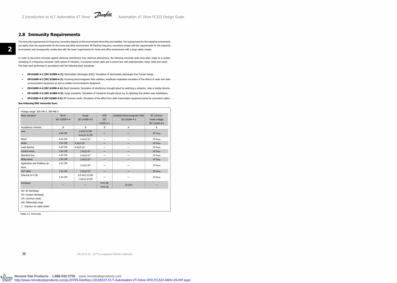
2.8 Immunity RequirementsThe immunity requirements for frequency converters depend on the environment where they are installed. The requirements for the industrial environment
are higher than the requirements for the home and office environment. All Danfoss frequency converters comply with the requirements for the industrial
environment and consequently comply also with the lower requirements for home and office environment with a large safety margin.
In order to document immunity against electrical interference from electrical phenomena, the following immunity tests have been made on a system
consisting of a frequency converter (with options if relevant), a screened control cable and a control box with potentiometer, motor cable and motor.
The tests were performed in accordance with the following basic standards:
• EN 61000-4-2 (IEC 61000-4-2): Electrostatic discharges (ESD): Simulation of electrostatic discharges from human beings.
• EN 61000-4-3 (IEC 61000-4-3): Incoming electromagnetic field radiation, amplitude modulated simulation of the effects of radar and radio
communication equipment as well as mobile communications equipment.
• EN 61000-4-4 (IEC 61000-4-4): Burst transients: Simulation of interference brought about by switching a contactor, relay or similar devices.
• EN 61000-4-5 (IEC 61000-4-5): Surge transients: Simulation of transients brought about e.g. by lightning that strikes near installations.
• EN 61000-4-6 (IEC 61000-4-6): RF Common mode: Simulation of the effect from radio-transmission equipment joined by connection cables.
See following EMC immunity form.
Voltage range: 200-240 V, 380-480 V
Basic standard Burst
IEC 61000-4-4
Surge
IEC 61000-4-5
ESD
IEC
61000-4-2
Radiated electromagnetic field
IEC 61000-4-3
RF common
mode voltage
IEC 61000-4-6
Acceptance criterion B B B A A
Line4 kV CM
2 kV/2 Ω DM
4 kV/12 Ω CM— — 10 VRMS
Motor 4 kV CM 4 kV/2 Ω1) — — 10 VRMS
Brake 4 kV CM 4 kV/2 Ω1) — — 10 VRMS
Load sharing 4 kV CM 4 kV/2 Ω1) — — 10 VRMS
Control wires 2 kV CM 2 kV/2 Ω1) — — 10 VRMS
Standard bus 2 kV CM 2 kV/2 Ω1) — — 10 VRMS
Relay wires 2 kV CM 2 kV/2 Ω1) — — 10 VRMS
Application and Fieldbus op-
tions
2 kV CM2 kV/2 Ω1) — — 10 VRMS
LCP cable 2 kV CM 2 kV/2 Ω1) — — 10 VRMS
External 24 V DC2 kV CM
0.5 kV/2 Ω DM
1 kV/12 Ω CM— — 10 VRMS
Enclosure— —
8 kV AD
6 kV CD10 V/m —
AD: Air Discharge
CD: Contact Discharge
CM: Common mode
DM: Differential mode
1. Injection on cable shield.
Table 2.2: Immunity
2 Introduction to VLT Automation VT Drive Automation VT Drive FC322 Design Guide
38 MG.20.X1.22 - VLT® is a registered Danfoss trademark
2
Remote Site Products - 1-888-532-2706 - www.remotesiteproducts.comhttp://www.remotesiteproducts.com/p-20795-Danfoss-131X8157-VLT-Automation-VT-Drive-VFD-FC322-460V-25-HP.aspx

2.9 Galvanic isolation (PELV)
2.11.1 PELV - Protective Extra Low Voltage
PELV offers protection by way of extra low voltage. Protection against electric shock is ensured when the electrical supply is of the PELV type and the
installation is made as described in local/national regulations on PELV supplies.
All control terminals and relay terminals 01-03/04-06 comply with PELV (Protective Extra Low Voltage) (Does not apply to grounded Delta leg above 400
V).
Galvanic (ensured) isolation is obtained by fulfilling requirements for higher isolation and by providing the relevant creapage/clearance distances. These
requirements are described in the EN 61800-5-1 standard.
The components that make up the electrical isolation, as described below, also comply with the requirements for higher isolation and the relevant test
as described in EN 61800-5-1.
The PELV galvanic isolation can be shown in six locations (see illustration):
In order to maintain PELV all connections made to the control terminals must be PELV, e.g. thermistor must be reinforced/double insulated.
1. Power supply (SMPS) incl. signal isolation of UDC, indicating the
intermediate current voltage.
2. Gate drive that runs the IGBTs (trigger transformers/opto-cou-
plers).
3. Current transducers.
4. Opto-coupler, brake module.
5. Internal inrush, RFI, and temperature measurement circuits.
6. Custom relays.
Illustration 2.5: Galvanic isolation
The functional galvanic isolation (a and b on drawing) is for the 24 V back-up option and for the RS 485 standard bus interface.
Installation at high altitude:
380 - 500 V, enclosure A, B and C: At altitudes above 2 km, please contact Danfoss regarding PELV.
380 - 500 V, enclosure D, E and F: At altitudes above 3 km, please contact Danfoss regarding PELV.
525 - 690 V: At altitudes above 2 km, please contact Danfoss regarding PELV.
Automation VT Drive FC322 Design Guide 2 Introduction to VLT Automation VT Drive
MG.20.X1.22 - VLT® is a registered Danfoss trademark 39
2
Remote Site Products - 1-888-532-2706 - www.remotesiteproducts.comhttp://www.remotesiteproducts.com/p-20795-Danfoss-131X8157-VLT-Automation-VT-Drive-VFD-FC322-460V-25-HP.aspx

2.10 Earth leakage current
Warning:
Touching the electrical ts may be fatal - even after the equipment has been disconnected from mains.
Also make sure that other voltage inputs have been disconnected, such as load sharing (linkage of DC intermediate circuit), as well as
the motor connection for kinetic back-up.
Before touching any electrical parts, wait at least the amount of time indicated in the Safety Precautions section.
Shorter time is allowed only if indicated on the nameplate for the specific unit.
Leakage Current
The earth leakage current from the frequency converter exceeds 3.5 mA. To ensure that the earth cable has a good mechanical
connection to the earth connection (terminal 95), the cable cross section must be at least 10 mm2 or 2 rated earth wires terminated
seately.
Residual Current Device
This product can cause a d.c. current in the protective conductor. Where a residual current device (RCD) is used for protection in case
of direct or indirect contact, only an RCD of Type B is allowed on the supply side of this product. Otherwise, another protective measure
shall be applied, such as separation from the environment by double or reinforced insulation, or isolation from the supply system by a
transformer. See also RCD Application Note MN.90.GX.02.
Protective earthing of the frequency converter and the use of RCD's must always follow national and local regulations.
2 Introduction to VLT Automation VT Drive Automation VT Drive FC322 Design Guide
40 MG.20.X1.22 - VLT® is a registered Danfoss trademark
2
Remote Site Products - 1-888-532-2706 - www.remotesiteproducts.comhttp://www.remotesiteproducts.com/p-20795-Danfoss-131X8157-VLT-Automation-VT-Drive-VFD-FC322-460V-25-HP.aspx
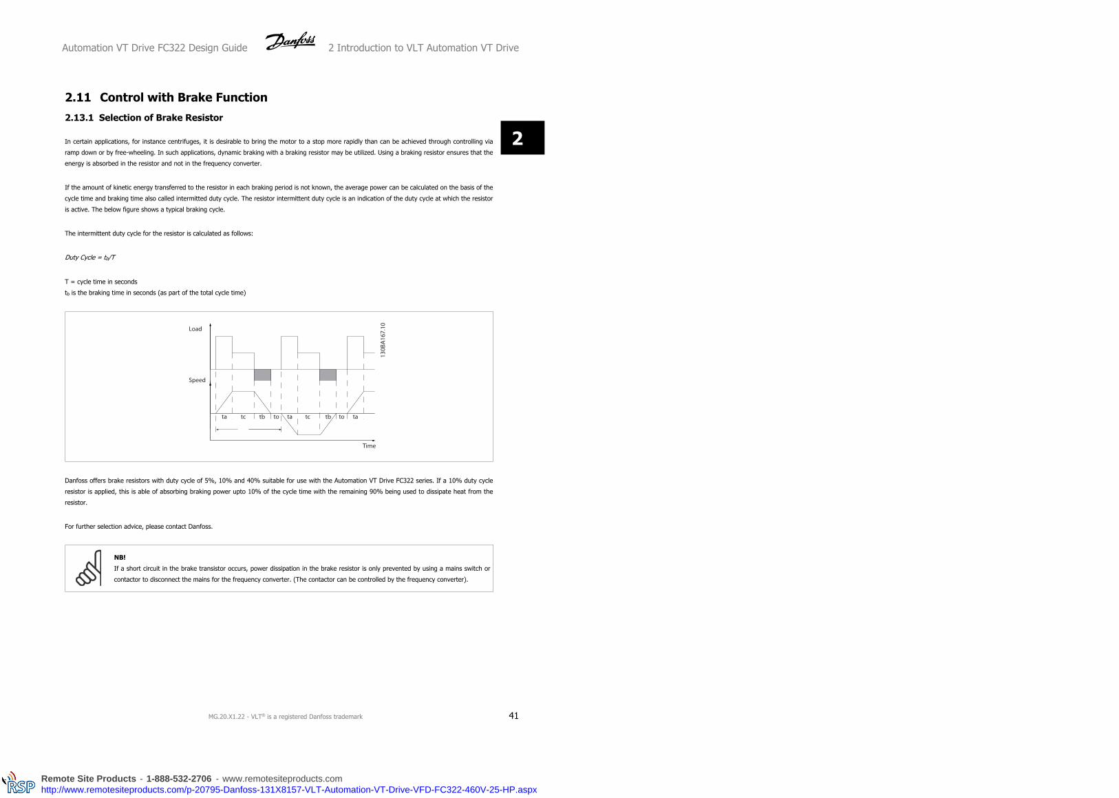
2.11 Control with Brake Function
2.13.1 Selection of Brake Resistor
In certain applications, for instance centrifuges, it is desirable to bring the motor to a stop more rapidly than can be achieved through controlling via
ramp down or by free-wheeling. In such applications, dynamic braking with a braking resistor may be utilized. Using a braking resistor ensures that the
energy is absorbed in the resistor and not in the frequency converter.
If the amount of kinetic energy transferred to the resistor in each braking period is not known, the average power can be calculated on the basis of the
cycle time and braking time also called intermitted duty cycle. The resistor intermittent duty cycle is an indication of the duty cycle at which the resistor
is active. The below figure shows a typical braking cycle.
The intermittent duty cycle for the resistor is calculated as follows:
Duty Cycle = tb/T
T = cycle time in seconds
tb is the braking time in seconds (as part of the total cycle time)
Danfoss offers brake resistors with duty cycle of 5%, 10% and 40% suitable for use with the Automation VT Drive FC322 series. If a 10% duty cycle
resistor is applied, this is able of absorbing braking power upto 10% of the cycle time with the remaining 90% being used to dissipate heat from the
resistor.
For further selection advice, please contact Danfoss.
NB!
If a short circuit in the brake transistor occurs, power dissipation in the brake resistor is only prevented by using a mains switch or
contactor to disconnect the mains for the frequency converter. (The contactor can be controlled by the frequency converter).
Automation VT Drive FC322 Design Guide 2 Introduction to VLT Automation VT Drive
MG.20.X1.22 - VLT® is a registered Danfoss trademark 41
2
Remote Site Products - 1-888-532-2706 - www.remotesiteproducts.comhttp://www.remotesiteproducts.com/p-20795-Danfoss-131X8157-VLT-Automation-VT-Drive-VFD-FC322-460V-25-HP.aspx

2.13.2 Control with Brake Function
The brake is protected against short-circuiting of the brake resistor, and the brake transistor is monitored to ensure that short-circuiting of the transistor
is detected. A relay/digital output can be used for protecting the brake resistor against overloading in connection with a fault in the frequency converter.
In addition, the brake makes it possible to read out the momentary power and the mean power for the latest 120 seconds. The brake can also monitor
the power energizing and make sure it does not exceed a limit selected in par. 2-12 Brake Power Limit (kW). In par. 2-13 Brake Power Monitoring, select
the function to carry out when the power transmitted to the brake resistor exceeds the limit set in par. 2-12 Brake Power Limit (kW).
NB!
Monitoring the brake power is not a safety function; a thermal switch is required for that purpose. The brake resistor circuit is not earth
leakage protected.
Over voltage control (OVC) (exclusive brake resistor) can be selected as an alternative brake function in par. 2-17 Over-voltage Control. This function is
active for all units. The function ensures that a trip can be avoided if the DC link voltage increases. This is done by increasing the output frequency to
limit the voltage from the DC link. It is a very useful function, e.g. if the ramp-down time is too short since tripping of the frequency converter is avoided.
In this situation the ramp-down time is extended.
2.12 Mechanical Brake Control
2.14.1 Brake Resistor Cabling
EMC (twisted cables/shielding)
To reduce the electrical noise from the wires between the brake resistor and the frequency converter, the wires must be twisted.
For enhanced EMC performance a metal screen can be used.
2.13 Extreme Running Conditions Short Circuit (Motor Phase – Phase)
The frequency converter is protected against short circuits by means of current measurement in each of the three motor phases or in the DC link. A short
circuit between two output phases will cause an overcurrent in the inverter. The inverter will be turned off individually when the short circuit current
exceeds the permitted value (Alarm 16 Trip Lock.
To protect the drive against a short circuit at the load sharing and brake outputs please see the design guidelines.
Switching on the Output
Switching on the output between the motor and the frequency converter is fully permitted. You cannot damage the frequency converter in any way by
switching on the output. However, fault messages may appear.
Motor-generated Overvoltage
The voltage in the intermediate circuit is increased when the motor acts as a generator.
This occurs in following cases:
1. The load drives the motor, ie. the load generates energy.
2. During deceleration ("ramp-down") if the moment of inertia is high, the friction is low and the ramp-down time is too short for the energy to be
dissipated as a loss in the frequency converter, the motor and the installation.
3. In-correct slip compensation setting may cause higher DC link voltage.
The control unit may attempt to correct the ramp if possible (par. 2-17 Over-voltage Control.
The inverter turns off to protect the transistors and the intermediate circuit capacitors when a certain voltage level is reached.
See par. 2-10 and par. 2-17 to select the method used for controlling the intermediate circuit voltage level.
High Temperature
High ambient temperature may overheat the frequency converter.
2 Introduction to VLT Automation VT Drive Automation VT Drive FC322 Design Guide
42 MG.20.X1.22 - VLT® is a registered Danfoss trademark
2
Remote Site Products - 1-888-532-2706 - www.remotesiteproducts.comhttp://www.remotesiteproducts.com/p-20795-Danfoss-131X8157-VLT-Automation-VT-Drive-VFD-FC322-460V-25-HP.aspx

Mains Drop-out
During a mains drop-out, the frequency converter keeps running until the intermediate circuit voltage drops below the minimum stop level, which is
typically 15% below the frequency converter's lowest rated supply voltage.
The mains voltage before the drop-out and the motor load determines how long it takes for the inverter to coast.
Static Overload in VVCplus mode
When the frequency converter is overloaded (the torque limit in par. 4-16/4-17 is reached), the controls reduces the output frequency to reduce the load.
If the overload is excessive, a current may occur that makes the frequency converter cut out after approx. 5-10 s.
Operation within the torque limit is limited in time (0-60 s) in par. 14-25.
2.15.1 Motor Thermal Protection
This is the way Danfoss is protecting the motor from being overheated. It is an electronic feature that simulates a bimetal relay based on internal
measurements. The characteristic is shown in the following figure:
Illustration 2.6: The X-axis is showing the ratio between Imotor and Imotor nominal. The Y- axis is showing the time in seconds before the ETR
cuts off and trips the drive. The curves are showing the characteristic nominal speed at twice the nominal speed and at 0,2x the nominal
speed.
It is clear that at lower speed the ETR cuts of at lower heat due to less cooling of the motor. In that way the motor are protected from being over heated
even at low speed. The ETR feature is calculating the motor temperature based on actual current and speed. The calculated temperature is visible as a
read out parameter in par. 16-18 Motor Thermal in the frequency converter.
The thermistor cut-out value is > 3 kΩ.
Integrate a thermistor (PTC sensor) in the motor for winding protection.
Motor protection can be implemented using a range of techniques: PTC
sensor in motor windings; mechanical thermal switch (Klixon type); or
Electronic Thermal Relay (ETR).
Automation VT Drive FC322 Design Guide 2 Introduction to VLT Automation VT Drive
MG.20.X1.22 - VLT® is a registered Danfoss trademark 43
2
Remote Site Products - 1-888-532-2706 - www.remotesiteproducts.comhttp://www.remotesiteproducts.com/p-20795-Danfoss-131X8157-VLT-Automation-VT-Drive-VFD-FC322-460V-25-HP.aspx

2 Introduction to VLT Automation VT Drive Automation VT Drive FC322 Design Guide
44 MG.20.X1.22 - VLT® is a registered Danfoss trademark
2
Remote Site Products - 1-888-532-2706 - www.remotesiteproducts.comhttp://www.remotesiteproducts.com/p-20795-Danfoss-131X8157-VLT-Automation-VT-Drive-VFD-FC322-460V-25-HP.aspx
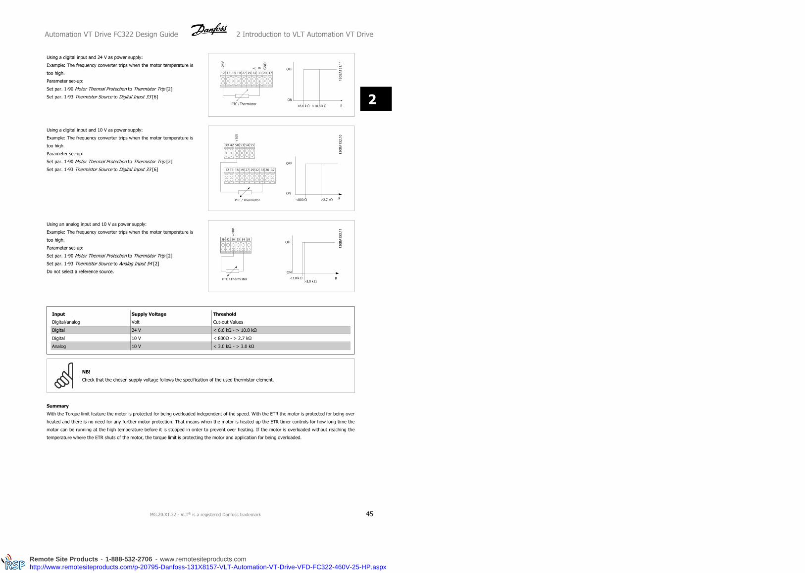
Using a digital input and 24 V as power supply:
Example: The frequency converter trips when the motor temperature is
too high.
Parameter set-up:
Set par. 1-90 Motor Thermal Protection to Thermistor Trip [2]
Set par. 1-93 Thermistor Source to Digital Input 33 [6]
Using a digital input and 10 V as power supply:
Example: The frequency converter trips when the motor temperature is
too high.
Parameter set-up:
Set par. 1-90 Motor Thermal Protection to Thermistor Trip [2]
Set par. 1-93 Thermistor Source to Digital Input 33 [6]
Using an analog input and 10 V as power supply:
Example: The frequency converter trips when the motor temperature is
too high.
Parameter set-up:
Set par. 1-90 Motor Thermal Protection to Thermistor Trip [2]
Set par. 1-93 Thermistor Source to Analog Input 54 [2]
Do not select a reference source.
Input
Digital/analog
Supply Voltage
Volt
Threshold
Cut-out Values
Digital 24 V < 6.6 kΩ - > 10.8 kΩ
Digital 10 V < 800Ω - > 2.7 kΩ
Analog 10 V < 3.0 kΩ - > 3.0 kΩ
NB!
Check that the chosen supply voltage follows the specification of the used thermistor element.
Summary
With the Torque limit feature the motor is protected for being overloaded independent of the speed. With the ETR the motor is protected for being over
heated and there is no need for any further motor protection. That means when the motor is heated up the ETR timer controls for how long time the
motor can be running at the high temperature before it is stopped in order to prevent over heating. If the motor is overloaded without reaching the
temperature where the ETR shuts of the motor, the torque limit is protecting the motor and application for being overloaded.
Automation VT Drive FC322 Design Guide 2 Introduction to VLT Automation VT Drive
MG.20.X1.22 - VLT® is a registered Danfoss trademark 45
2
Remote Site Products - 1-888-532-2706 - www.remotesiteproducts.comhttp://www.remotesiteproducts.com/p-20795-Danfoss-131X8157-VLT-Automation-VT-Drive-VFD-FC322-460V-25-HP.aspx

NB!
ETR is activated in par. and is controlled in par. 4-16 Torque Limit Motor Mode. The time before the torque limit warning trips the frequency converter
is set in par. 14-25 Trip Delay at Torque Limit.
2 Introduction to VLT Automation VT Drive Automation VT Drive FC322 Design Guide
46 MG.20.X1.22 - VLT® is a registered Danfoss trademark
2
Remote Site Products - 1-888-532-2706 - www.remotesiteproducts.comhttp://www.remotesiteproducts.com/p-20795-Danfoss-131X8157-VLT-Automation-VT-Drive-VFD-FC322-460V-25-HP.aspx
2.15.2 Safe Stop Operation (Optional)
The FC322 can perform the Safety Function “Uncontrolled Stopping by removal of power” (as defined by draft IEC 61800-5-2) or Stop Category 0 (as
defined in EN 60204-1).
It is designed and approved suitable for the requirements of Safety Category 3 in EN 954-1. This functionality is called Safe Stop.
Prior to integration and use of FC322 Safe Stop in an installation, a thorough risk analysis on the installation must be carried out in order to determine
whether the FC322 Safe Stop functionality and safety category are appropriate and sufficient.
The Safe Stop function is activated by removing the voltage at Terminal 37 of the Safe Inverter. By connecting the Safe Inverter to external safety devices
providing a safe relay, an installation for a safe Stop Category 1 can be obtained. The Safe Stop function of FC322 can be used for asynchronous and
synchronous motors.
Safe Stop activation (i.e. removal of 24 V DC voltage supply to terminal 37) does not provide electrical safety.
NB!
The Safe Stop function of FC322 can be used for asynchronous and synchronous motors. It may happen that two faults occur in the
frequency converter's power semiconductor. When using synchronous motors this may cause a residual rotation. The rotation can be
calculated to Angle=360/(Number of Poles). The application using synchronous motors must take this into consideration and ensure
that this is not a safety critical issue. This situation is not relevant for asynchronous motors.
NB!
In order to use the Safe Stop functionality in conformance with the requirements of EN-954-1 Category 3, a number of conditions must
be fulfilled by the installation of Safe Stop. Please see section Safe Stop Installation for further information.
NB!
The frequency converter does not provide a safety-related protection against unintended or malicious voltage supply to terminal 37
and subsequent reset. Provide this protection via the interrupt device, at the application level, or organisational level.
For more information - see section Safe Stop Installation.
Automation VT Drive FC322 Design Guide 2 Introduction to VLT Automation VT Drive
MG.20.X1.22 - VLT® is a registered Danfoss trademark 47
2
Remote Site Products - 1-888-532-2706 - www.remotesiteproducts.comhttp://www.remotesiteproducts.com/p-20795-Danfoss-131X8157-VLT-Automation-VT-Drive-VFD-FC322-460V-25-HP.aspx
3 VLT Automation VT Drive Selection Automation VT Drive FC322 Design Guide
48 MG.20.X1.22 - VLT® is a registered Danfoss trademark
3
Remote Site Products - 1-888-532-2706 - www.remotesiteproducts.comhttp://www.remotesiteproducts.com/p-20795-Danfoss-131X8157-VLT-Automation-VT-Drive-VFD-FC322-460V-25-HP.aspx

3 VLT Automation VT Drive Selection
3.1 General Specifications
Automation VT Drive FC322 Design Guide 3 VLT Automation VT Drive Selection
MG.20.X1.22 - VLT® is a registered Danfoss trademark 49
3
Remote Site Products - 1-888-532-2706 - www.remotesiteproducts.comhttp://www.remotesiteproducts.com/p-20795-Danfoss-131X8157-VLT-Automation-VT-Drive-VFD-FC322-460V-25-HP.aspx

Mai
ns
Supp
ly 1
x 2
00 -
240
VA
C -
Nor
mal
ove
rloa
d 11
0% f
or 1
min
ute
Freq
uenc
y co
nver
ter
Typi
cal S
haft
Out
put
[kW
]P1
K11.
1P1
K51.
5P2
K22.
2P3
K03.
0P3
K73.
7P5
K55.
5P7
K57.
5P1
5K0
15P2
2K0
22
Typi
cal S
haft
Out
put
[HP]
at
240
V1.
52.
02.
94.
04.
97.
510
2030
IP 2
0 /
Chas
sis
A3
--
--
--
--
IP 2
1 /
NEM
A 1
-
B1B1
B1B1
B1B2
C1C2
IP 5
5 /
NEM
A 12
A5
B1B1
B1B1
B1B2
C1C2
IP 6
6
A5B1
B1B1
B1B1
B2C1
C2O
utp
ut c
urr
ent
Cont
inuo
us(3
x 2
00-2
40 V
) [A
]6.
67.
510
.612
.516
.724
.230
.859
.488
Inte
rmitt
ent
(3 x
200
-240
V)
[A]
7.3
8.3
11.7
13.8
18.4
26.6
33.4
65.3
96.8
Cont
inuo
us k
VA(2
08 V
AC)
[kV
A]
5.00
6.40
12.2
718
.30
Max
. cab
le s
ize:
(mai
ns, m
otor
, bra
ke)
[[m
m2 /
AW
G]
2)0.
2-4
/ 4-
1010
/735
/250
/1/0
95/4
/0
Max
. inp
ut c
urr
ent
Cont
inuo
us(1
x 2
00-2
40 V
) [
A]12
.515
20.5
2432
4659
111
172
Inte
rmitt
ent
(1 x
200
-240
V )
[A]
13.8
16.5
22.6
26.4
35.2
50.6
64.9
122.
118
9.2
Max
. pre
-fus
es1)
[A]
2030
4040
6080
100
150
200
Envi
ronm
ent
Estim
ated
pow
er lo
ssat
rat
ed m
ax. l
oad
[W]
4)44
3044
6074
110
150
300
440
Wei
ght
encl
osur
e IP
20
[kg]
4.9
--
--
--
--
Wei
ght
encl
osur
e IP
21
[kg]
-23
2323
2323
2745
65W
eigh
t en
clos
ure
IP 5
5 [k
g]-
2323
2323
2327
4565
Wei
ght
encl
osur
e IP
66
[kg]
-23
2323
2323
2745
65Ef
ficie
ncy
3)0.
968
0.98
0.98
0.98
0.98
0.98
0.98
0.98
0.98
3.1
.1M
ain
s Su
pply
1 x
20
0 -
24
0 V
AC
3 VLT Automation VT Drive Selection Automation VT Drive FC322 Design Guide
50 MG.20.X1.22 - VLT® is a registered Danfoss trademark
3
Remote Site Products - 1-888-532-2706 - www.remotesiteproducts.comhttp://www.remotesiteproducts.com/p-20795-Danfoss-131X8157-VLT-Automation-VT-Drive-VFD-FC322-460V-25-HP.aspx

Nor
mal
ove
rloa
d 11
0%
for
1 m
inu
teIP
20
/ N
EMA
Chas
sis
A2
A2A2
A2A2
A2A2
A3A3
IP 2
1 /
NEM
A 1
A2
A2A2
A2A2
A2A2
A3A3
IP 5
5 /
NEM
A 12
A5
A5A5
A5A5
A5A5
A5A5
IP 6
6
A5A5
A5A5
A5A5
A5A5
A5M
ain
s su
pply
200
- 2
40 V
AC
Freq
uenc
y co
nver
ter
Typi
cal S
haft
Out
put
[kW
]PK
250.
25PK
370.
37PK
550.
55PK
750.
75P1
K11.
1P1
K51.
5P2
K22.
2P3
K0 3P3
K73.
7Ty
pica
l Sha
ft O
utpu
t [H
P] a
t 20
8 V
0.25
0.37
0.55
0.75
1.5
2.0
2.9
4.0
4.9
Ou
tput
cu
rren
t
Cont
inuo
us(3
x 2
00-2
40 V
) [
A]1.
82.
43.
54.
66.
67.
510
.612
.516
.7
Inte
rmitt
ent
(3 x
200
-240
V )
[A]
1.98
2.64
3.85
5.06
7.26
8.3
11.7
13.8
18.4
Cont
inuo
uskV
A (2
08 V
AC)
[kV
A]0.
650.
861.
261.
662.
382.
703.
824.
506.
00
Max
. ca
ble
size
:(m
ains
, mot
or, b
rake
)[m
m2
/AW
G]
2)0.
2 -
4 m
m2
/ 4
- 10
AW
G
Max
. inp
ut c
urr
ent
Cont
inuo
us(3
x 2
00-2
40 V
) [
A]1.
62.
23.
24.
15.
96.
89.
511
.315
.0
Inte
rmitt
ent
(3 x
200
-240
V )
[A]
1.7
2.42
3.52
4.51
6.5
7.5
10.5
12.4
16.5
Max
. pr
e-fu
ses1
) [A]
1010
1010
2020
2032
32En
viro
nmen
tEs
timat
ed p
ower
loss
at r
ated
max
. loa
d [W
] 4)
2129
4254
6382
116
155
185
Wei
ght
encl
osur
e IP
20 [
kg]
4.9
4.9
4.9
4.9
4.9
4.9
4.9
6.6
6.6
Wei
ght
encl
osur
e IP
21 [
kg]
5.5
5.5
5.5
5.5
5.5
5.5
5.5
7.5
7.5
Wei
ght
encl
osur
e IP
55 [
kg]
13.5
13.5
13.5
13.5
13.5
13.5
13.5
13.5
13.5
Wei
ght
encl
osur
e IP
66
[kg]
13.5
13.5
13.5
13.5
13.5
13.5
13.5
13.5
13.5
Effic
ienc
y 3)
0.94
0.94
0.95
0.95
0.96
0.96
0.96
0.96
0.96
3.1
.2M
ain
s Su
pply
3 x
20
0 -
24
0 V
AC
Automation VT Drive FC322 Design Guide 3 VLT Automation VT Drive Selection
MG.20.X1.22 - VLT® is a registered Danfoss trademark 51
3
Remote Site Products - 1-888-532-2706 - www.remotesiteproducts.comhttp://www.remotesiteproducts.com/p-20795-Danfoss-131X8157-VLT-Automation-VT-Drive-VFD-FC322-460V-25-HP.aspx

Mai
ns
supp
ly 3
x 2
00 -
240
VA
C -
Nor
mal
ove
rloa
d 11
0% f
or 1
min
ute
IP 2
0 /
NEM
A Ch
assi
s(B
3+4
and
C3+
4 m
ay b
e co
nver
ted
to I
P21
usin
g a
conv
ersi
on k
it (P
leas
e co
ntac
t D
anfo
ss)
B3B3
B3B4
B4C3
C3C4
C4
IP 2
1 /
NEM
A 1
B1
B1B1
B2C1
C1C1
C2C2
IP 5
5 /
NEM
A 12
B1
B1B1
B2C1
C1C1
C2C2
IP 6
6
B1B1
B1B2
C1C1
C1C2
C2Fr
eque
ncy
conv
erte
rTy
pica
l Sha
ft O
utpu
t [k
W]
P5K5
5.5
P7K5
7.5
P11K 11
P15K 15
P18K
18.5
P22K 22
P30K 30
P37K 37
P45K 45
Typi
cal S
haft
Out
put
[HP]
at
208
V7.
510
1520
2530
4050
60O
utp
ut c
urr
ent
Cont
inuo
us(3
x 2
00-2
40 V
) [
A]24
.230
.846
.259
.474
.888
.011
514
317
0
Inte
rmitt
ent
(3 x
200
-240
V )
[A]
26.6
33.9
50.8
65.3
82.3
96.8
127
157
187
Cont
inuo
uskV
A (2
08 V
AC)
[kV
A]8.
711
.116
.621
.426
.931
.741
.451
.561
.2
Max
. cab
le s
ize:
(mai
ns, m
otor
, bra
ke)
[mm
2 /A
WG
] 2)
10/7
35/2
50/1
/095
/4/0
120/
250
MCM
Max
. inp
ut c
urr
ent
Cont
inuo
us(3
x 2
00-2
40 V
) [
A]22
.028
.042
.054
.068
.080
.010
4.0
130.
015
4.0
Inte
rmitt
ent
(3 x
200
-240
V )
[A]
24.2
30.8
46.2
59.4
74.8
88.0
114.
014
3.0
169.
0
Max
. pre
-fus
es1)
[A]
6363
6380
125
125
160
200
250
Envi
ronm
ent:
Estim
ated
pow
er lo
ssat
rat
ed m
ax. l
oad
[W]
4)26
931
044
760
273
784
511
4013
5316
36
Wei
ght
encl
osur
e IP
20 [
kg]
1212
1223
.523
.535
3550
50W
eigh
t en
clos
ure
IP21
[kg
]23
2323
2745
4565
6565
Wei
ght
encl
osur
e IP
55 [
kg]
2323
2327
4545
6565
65W
eigh
t en
clos
ure
IP 6
6 [k
g]23
2323
2745
4565
6565
Effic
ienc
y 3)
0.96
0.96
0.96
0.96
0.96
0.97
0.97
0.97
0.97
3 VLT Automation VT Drive Selection Automation VT Drive FC322 Design Guide
52 MG.20.X1.22 - VLT® is a registered Danfoss trademark
3
Remote Site Products - 1-888-532-2706 - www.remotesiteproducts.comhttp://www.remotesiteproducts.com/p-20795-Danfoss-131X8157-VLT-Automation-VT-Drive-VFD-FC322-460V-25-HP.aspx

Mai
ns
Supp
ly 1
x 38
0 V
AC
- N
orm
al o
verl
oad
110%
for
1 m
inu
teFr
eque
ncy
conv
erte
rTy
pica
l Sha
ft O
utpu
t [k
W]
P7K5
7.5
P11K 11
P18K
18.5
P37K 37
Typi
cal S
haft
Out
put
[HP]
at
460
V10
1525
50IP
21
/ N
EMA
1
B1B2
C1C2
IP 5
5 /
NEM
A 12
B1
B2C1
C2IP
66
B1
B2C1
C2O
utp
ut c
urr
ent
Cont
inuo
us(3
x 3
80-4
40 V
) [A
]16
2437
.573
Inte
rmitt
ent
(3 x
380
-440
V)
[A]
17.6
26.4
41.2
80.3
Cont
inuo
us(3
x 4
41-4
80 V
) [A
]14
.521
3465
Inte
rmitt
ent
(3 x
441
-480
V)
[A]
15.4
23.1
37.4
71.5
Cont
inuo
us k
VA(4
00 V
AC)
[kV
A]11
.016
.626
50.6
Cont
inuo
us k
VA(4
60 V
AC)
[kV
A]11
.616
.727
.151
.8
Max
. ca
ble
size
:(m
ains
, mot
or, b
rake
)[[
mm
2 / A
WG
] 2)
10/7
35/2
50/1
/012
0/4/
0
Max
. inp
ut c
urr
ent
Cont
inuo
us(1
x 3
80-4
40 V
) [
A]33
4878
151
Inte
rmitt
ent
(1 x
380
-440
V )
[A]
3653
85.8
166
Cont
inuo
us(1
x 4
41-4
80 V
) [A
]30
4172
135
Inte
rmitt
ent
(1 x
441
-480
V)
[A]
3346
79.2
148
Max
. pr
e-fu
ses1
) [A]
6380
160
250
Envi
ronm
ent
Estim
ated
pow
er lo
ssat
rat
ed m
ax. l
oad
[W]
4)30
044
074
014
80
Wei
ght
encl
osur
e IP
21
[kg]
2327
4565
Wei
ght
encl
osur
e IP
55
[kg]
2327
4565
Wei
ght
encl
osur
e IP
66
[kg]
2327
4565
Effic
ienc
y 3)
0.96
0.96
0.96
0.96
3.1
.3M
ain
s Su
pply
1 x
38
0 -
48
0 V
AC
Automation VT Drive FC322 Design Guide 3 VLT Automation VT Drive Selection
MG.20.X1.22 - VLT® is a registered Danfoss trademark 53
3
Remote Site Products - 1-888-532-2706 - www.remotesiteproducts.comhttp://www.remotesiteproducts.com/p-20795-Danfoss-131X8157-VLT-Automation-VT-Drive-VFD-FC322-460V-25-HP.aspx

Mai
ns
Supp
ly 3
x 3
80 -
480
VA
C -
Nor
mal
ove
rloa
d 11
0% f
or 1
min
ute
Freq
uenc
y co
nver
ter
Typi
cal S
haft
Out
put
[kW
]PK
370.
37PK
550.
55PK
750.
75P1
K11.
1P1
K51.
5P2
K22.
2P3
K0 3P4
K0 4P5
K55.
5P7
K57.
5Ty
pica
l Sha
ft O
utpu
t [H
P] a
t 46
0 V
0.5
0.75
1.0
1.5
2.0
2.9
4.0
5.3
7.5
10IP
20
/ N
EMA
Chas
sis
A2A2
A2A2
A2A2
A2A2
A3A3
IP 2
1 /
NEM
A 1
IP
55
/ N
EMA
12
A5A5
A5A5
A5A5
A5A5
A5A5
IP 6
6
A5A5
A5A5
A5A5
A5A5
AAA5
Ou
tput
cu
rren
tCo
ntin
uous
(3 x
380
-440
V)
[A]
1.3
1.8
2.4
34.
15.
67.
210
1316
Inte
rmitt
ent
(3 x
380
-440
V)
[A]
1.43
1.98
2.64
3.3
4.5
6.2
7.9
1114
.317
.6
Cont
inuo
us(3
x 4
41-4
80 V
) [A
]1.
21.
62.
12.
73.
44.
86.
38.
211
14.5
Inte
rmitt
ent
(3 x
441
-480
V)
[A]
1.32
1.76
2.31
3.0
3.7
5.3
6.9
9.0
12.1
15.4
Cont
inuo
us k
VA(4
00 V
AC)
[kV
A]0.
91.
31.
72.
12.
83.
95.
06.
99.
011
.0
Cont
inuo
us k
VA(4
60 V
AC)
[kV
A]0.
91.
31.
72.
42.
73.
85.
06.
58.
811
.6
Max
. cab
le s
ize:
(mai
ns, m
otor
, bra
ke)
[[m
m2 /
AW
G]
2)4/
10
Max
. inp
ut c
urr
ent
Cont
inuo
us(3
x 3
80-4
40 V
) [
A]1.
21.
62.
22.
73.
75.
06.
59.
011
.714
.4
Inte
rmitt
ent
(3 x
380
-440
V )
[A]
1.32
1.76
2.42
3.0
4.1
5.5
7.2
9.9
12.9
15.8
Cont
inuo
us(3
x 4
41-4
80 V
) [A
]1.
01.
41.
92.
73.
14.
35.
77.
49.
913
.0
Inte
rmitt
ent
(3 x
441
-480
V)
[A]
1.1
1.54
2.09
3.0
3.4
4.7
6.3
8.1
10.9
14.3
Max
. pre
-fus
es1)
[A]
1010
1010
1020
2020
3030
Envi
ronm
ent
Estim
ated
pow
er lo
ssat
rat
ed m
ax. l
oad
[W]
4)35
4246
5862
8811
612
418
725
5
Wei
ght
encl
osur
e IP
20 [
kg]
4.7
4.7
4.8
4.8
4.9
4.9
4.9
4.9
6.6
6.6
Wei
ght
encl
osur
e IP
21
[kg]
Wei
ght
encl
osur
e IP
55
[kg]
13.5
13.5
13.5
13.5
13.5
13.5
13.5
13.5
14.2
14.2
Wei
ght
encl
osur
e IP
66
[kg]
13.5
13.5
13.5
13.5
13.5
13.5
13.5
13.5
14.2
14.2
Effic
ienc
y 3)
0.93
0.95
0.96
0.96
0.97
0.97
0.97
0.97
0.97
0.97
3.1
.4M
ain
s Su
pply
3 x
38
0 -
48
0 V
AC
3 VLT Automation VT Drive Selection Automation VT Drive FC322 Design Guide
54 MG.20.X1.22 - VLT® is a registered Danfoss trademark
3
Remote Site Products - 1-888-532-2706 - www.remotesiteproducts.comhttp://www.remotesiteproducts.com/p-20795-Danfoss-131X8157-VLT-Automation-VT-Drive-VFD-FC322-460V-25-HP.aspx

Mai
ns
Supp
ly 3
x 3
80 -
480
VA
C -
Nor
mal
ove
rloa
d 11
0% f
or 1
min
ute
Freq
uenc
y co
nver
ter
Typi
cal S
haft
Out
put
[kW
]P1
1K 11P1
5K 15P1
8K18
.5P2
2K 22P3
0K 30P3
7K 37P4
5K 45P5
5K 55P7
5K 75P9
0K 90
Typi
cal S
haft
Out
put
[HP]
at
460
V15
2025
3040
5060
7510
012
5IP
20
/ N
EMA
Chas
sis
(B3+
4 an
d C3
+4
may
be
conv
erte
d to
IP2
1 us
ing
a co
nver
sion
kit
(Ple
ase
cont
act
Dan
foss
)B3
B3B3
B4B4
B4C3
C3C4
C4
IP 2
1 /
NEM
A 1
B1
B1B1
B2B2
C1C1
C1C2
C2IP
55
/ N
EMA
12
B1B1
B1B2
B2C1
C1C1
C2C2
IP 6
6
B1B1
B1B2
B2C1
C1C1
C2C2
Ou
tput
cu
rren
tCo
ntin
uous
(3 x
380
-440
V)
[A]
2432
37.5
4461
7390
106
147
177
Inte
rmitt
ent
(3 x
380
-440
V)
[A]
26.4
35.2
41.3
48.4
67.1
80.3
9911
716
219
5
Cont
inuo
us(3
x 4
41-4
80 V
) [A
]21
2734
4052
6580
105
130
160
Inte
rmitt
ent
(3 x
441
-480
V)
[A]
23.1
29.7
37.4
4461
.671
.588
116
143
176
Cont
inuo
us k
VA(4
00 V
AC)
[kV
A]16
.622
.226
30.5
42.3
50.6
62.4
73.4
102
123
Cont
inuo
us k
VA(4
60 V
AC)
[kV
A]16
.721
.527
.131
.941
.451
.863
.783
.710
412
8
Max
. ca
ble
size
:(m
ains
, mot
or, b
rake
)[[
mm
2 / A
WG
] 2)
10/7
35/2
50/1
/012
0/4/
012
0/4/
0
Max
. inp
ut c
urr
ent
Cont
inuo
us(3
x 3
80-4
40 V
) [
A]22
2934
4055
6682
9613
316
1
Inte
rmitt
ent
(3 x
380
-440
V )
[A]
24.2
31.9
37.4
4460
.572
.690
.210
614
617
7
Cont
inuo
us(3
x 4
41-4
80 V
) [A
]19
2531
3647
5973
9511
814
5
Inte
rmitt
ent
(3 x
441
-480
V)
[A]
20.9
27.5
34.1
39.6
51.7
64.9
80.3
105
130
160
Max
. pr
e-fu
ses1
) [A]
6363
6363
8010
012
516
025
025
0En
viro
nmen
tEs
timat
ed p
ower
loss
at r
ated
max
. loa
d [W
] 4)
278
392
465
525
698
739
843
1083
1384
1474
Wei
ght
encl
osur
e IP
20 [
kg]
1212
1223
.523
.523
.535
3550
50W
eigh
t en
clos
ure
IP 2
1 [k
g]23
2323
2727
4545
4565
65W
eigh
t en
clos
ure
IP 5
5 [k
g]23
2323
2727
4545
4565
65W
eigh
t en
clos
ure
IP 6
6 [k
g]23
2323
2727
4545
4565
65Ef
ficie
ncy
3)0.
980.
980.
980.
980.
980.
980.
980.
980.
980.
99
Automation VT Drive FC322 Design Guide 3 VLT Automation VT Drive Selection
MG.20.X1.22 - VLT® is a registered Danfoss trademark 55
3
Remote Site Products - 1-888-532-2706 - www.remotesiteproducts.comhttp://www.remotesiteproducts.com/p-20795-Danfoss-131X8157-VLT-Automation-VT-Drive-VFD-FC322-460V-25-HP.aspx
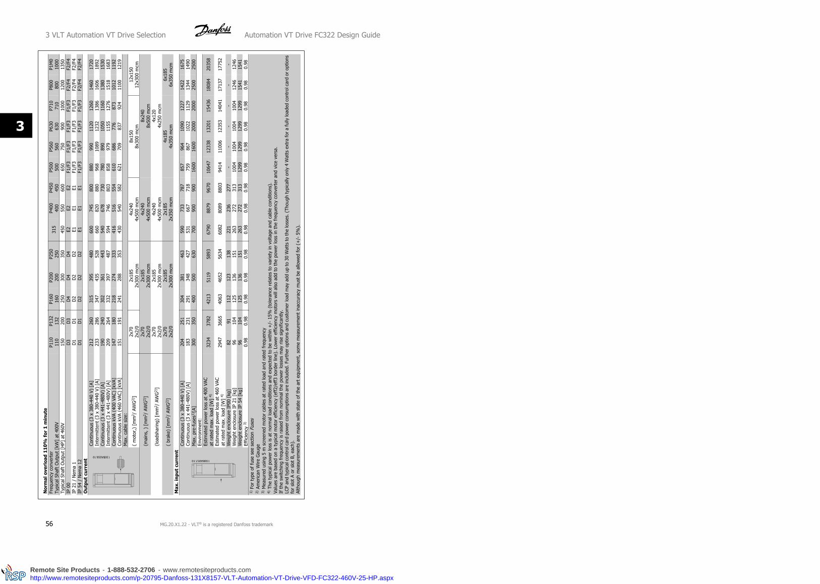
Nor
mal
ove
rloa
d 11
0%
for
1 m
inu
teFr
eque
ncy
conv
erte
rTy
pica
l Sha
ft O
utpu
t [k
W]
at 4
00V
P110
110
P132
132
P160
160
P200
200
P250
250
315
P400
400
P450
450
P500
500
P560
560
P630
630
P710
710
P800
800
P1M
010
00Ty
pica
l Sha
ft O
utpu
t [H
P] a
t 46
0V15
020
025
030
035
045
055
060
065
075
090
010
0012
0013
50IP
00
D
3D
3D
4D
4D
4E2
E2E2
F1/F
3F1
/F3
F1/F
3F1
/F3
F2/F
4F2
/F4
IP 2
1 /
Nem
a 1
D
1D
1D
2D
2D
2E1
E1E1
F1/F
3F1
/F3
F1/F
3F1
/F3
F2/F
4F2
/F4
IP 5
4 /
Nem
a 12
D
1D
1D
2D
2D
2E1
E1E1
F1/F
3F1
/F3
F1/F
3F1
/F3
F2/F
4F2
/F4
Ou
tput
cu
rren
tCo
ntin
uous
(3
x 38
0-44
0 V)
[A]
212
260
315
395
480
600
745
800
880
990
1120
1260
1460
1720
Inte
rmitt
ent
(3 x
380
-440
V)
[A]
233
286
347
435
528
660
820
880
968
1089
1232
1386
1606
1892
Cont
inuo
us (
3 x
441-
480V
) [A
]19
024
030
236
144
354
067
873
078
089
010
5011
6013
8015
30In
term
itten
t (3
x 4
41-4
80V)
[A]
209
264
332
397
487
594
746
803
858
979
1155
1276
1518
1683
Cont
inuo
us k
VA (
400
VAC)
[kV
A]14
718
021
827
433
341
651
655
461
068
677
687
310
1211
92Co
ntin
uous
kVA
(46
0 VA
C) [
kVA]
151
191
241
288
353
430
540
582
621
709
837
924
1100
1219
Max
. cab
le s
ize:
( m
otor
,) [
mm
2 / A
WG
2)]
2x70
2x2/
02x
185
2x30
0 m
cm4x
240
4x50
0 m
cm8x
150
8x30
0 m
cm12
x150
12x3
00 m
cm
(m
ains
, ) [
mm
2 / A
WG
2)]
2x70
2x2/
02x
185
2x30
0 m
cm4x
240
4x50
0 m
cm8x
240
8x50
0 m
cm
(lo
adsh
arin
g) [
mm
2 / A
WG
2)]
2x70
2x2/
02x
185
2x30
0 m
cm4x
240
4x50
0 m
cm4x
120
4x25
0 m
cm
(
brak
e) [
mm
2 / A
WG
2)]
2x70
2x2/
02x
185
2x30
0 m
cm2x
185
2x35
0 m
cm4x
185
4x35
0 m
cm6x
185
6x35
0 m
cmM
ax. i
nput
cu
rren
tCo
ntin
uous
(3
x 38
0-44
0 V)
[A]
204
251
304
381
463
590
733
787
857
964
1090
1227
1422
1675
Cont
inuo
us (
3 x
441-
480V
) [A
]18
323
129
134
842
753
166
771
875
986
710
2211
2913
4414
90M
ax. p
re-f
uses
1)[A
]30
035
040
050
063
070
090
090
016
0016
0020
0020
0025
0025
00En
viro
nmen
t:Es
timat
ed p
ower
loss
at
400
VAC
at r
ated
max
. loa
d [W
] 4)
3234
3782
4213
5119
5893
6790
8879
9670
1064
712
338
1320
115
436
1808
420
358
Estim
ated
pow
er lo
ss a
t 46
0 VA
Cat
rat
ed m
ax. l
oad
[W]
4)29
4736
6540
6346
5256
3460
8280
8988
0394
1411
006
1235
314
041
1713
717
752
Wei
ght
encl
osur
e IP
00 [
kg]
8291
112
123
138
221
236
277
--
--
--
Wei
ght
encl
osur
e IP
21
[kg]
9610
412
513
615
126
327
231
310
0410
0410
0410
0412
4612
46W
eigh
t en
clos
ure
IP 5
4 [k
g]96
104
125
136
151
263
272
313
1299
1299
1299
1299
1541
1541
Effic
ienc
y 3)
0.98
0.98
0.98
0.98
0.98
0.98
0.98
0.98
0.98
0.98
0.98
0.98
0.98
0.98
1) F
or t
ype
of f
use
see
sect
ion
Fuse
s2)
Am
eric
an W
ire G
auge
3) M
easu
red
usin
g 5
m s
cree
ned
mot
or c
able
s at
rat
ed lo
ad a
nd r
ated
fre
quen
cy4)
The
typ
ical
pow
er lo
ss is
at
norm
al lo
ad c
ondi
tions
and
exp
ecte
d to
be
with
in +
/- 1
5% (
tole
ranc
e re
late
s to
var
iety
in v
olta
ge a
nd c
able
con
ditio
ns).
Valu
es a
re b
ased
on
a ty
pica
l mot
or e
ffic
ienc
y (e
ff2/
eff3
bor
der
line)
. Low
er e
ffic
ienc
y m
otor
s w
ill a
lso
add
to t
he p
ower
loss
in t
he f
requ
ency
con
vert
er a
nd v
ice
vers
a.If
the
sw
itchi
ng f
requ
ency
is r
aise
d fr
om n
omin
al t
he p
ower
loss
es m
ay r
ise
sign
ifica
ntly
.LC
P an
d ty
pica
l con
trol
car
d po
wer
con
sum
ptio
ns a
re in
clud
ed. F
urth
er o
ptio
ns a
nd c
usto
mer
load
may
add
up
to 3
0 W
atts
to th
e lo
sses
. (Th
ough
typi
cally
onl
y 4
Wat
ts e
xtra
for a
fully
load
ed c
ontr
ol c
ard
or o
ptio
nsfo
r sl
ot A
or
slot
B, e
ach)
.Al
thou
gh m
easu
rem
ents
are
mad
e w
ith s
tate
of th
e ar
t eq
uipm
ent,
som
e m
easu
rem
ent
inac
cura
cy m
ust
be a
llow
ed f
or (
+/-
5%
).
3 VLT Automation VT Drive Selection Automation VT Drive FC322 Design Guide
56 MG.20.X1.22 - VLT® is a registered Danfoss trademark
3
Remote Site Products - 1-888-532-2706 - www.remotesiteproducts.comhttp://www.remotesiteproducts.com/p-20795-Danfoss-131X8157-VLT-Automation-VT-Drive-VFD-FC322-460V-25-HP.aspx

Nor
mal
ove
rloa
d 11
0%
for
1 m
inu
teSi
ze:
PK75
P1K1
P1K5
P2K2
P3K0
P4K0
P5K5
P7K5
P11K
P15K
P18K
P22K
P30K
P37K
P45K
P55K
P75K
P90K
Typi
cal S
haft
Out
put
[kW
]0.
751.
11.
52.
23
45.
57.
511
1518
.522
3037
4555
7590
IP 2
0 /
NEM
A Ch
assi
sA2
A2A2
A2A2
A2A3
A3B3
B3B3
B4B4
B4C3
C3C4
C4IP
21
/ N
EMA
1A2
A2A2
A2A2
A2A3
A3B1
B1B1
B2B2
B2C1
C1C2
C2IP
55
/ N
EMA
12A5
A5A5
A5A5
A5A5
A5B1
B1B1
B2B2
B2C1
C1C2
C2IP
66
A5A5
A5A5
A5A5
A5A5
B1B1
B1B2
B2B2
C1C1
C2C2
Ou
tput
cu
rren
tCo
ntin
uous
(3 x
525
-550
V )
[A]
1.8
2.6
2.9
4.1
5.2
6.4
9.5
11.5
1923
2836
4354
6587
105
137
Inte
rmitt
ent
(3 x
525
-550
V )
[A]
2.9
3.2
4.5
5.7
7.0
10.5
12.7
2125
3140
4759
7296
116
151
Cont
inuo
us(3
x 5
25-6
00 V
) [
A]1.
72.
42.
73.
94.
96.
19.
011
.018
2227
3441
5262
8310
013
1
Inte
rmitt
ent
(3 x
525
-600
V )
[A]
2.6
3.0
4.3
5.4
6.7
9.9
12.1
2024
3037
4557
6891
110
144
Cont
inuo
us k
VA (
525
V AC
)[k
VA]
1.7
2.5
2.8
3.9
5.0
6.1
9.0
11.0
18.1
21.9
26.7
34.3
4151
.461
.982
.910
013
0.5
Cont
inuo
us k
VA (
575
V AC
)[k
VA]
1.7
2.4
2.7
3.9
4.9
6.1
9.0
11.0
17.9
21.9
26.9
33.9
40.8
51.8
61.7
82.7
99.6
130.
5
Max
. cab
le s
ize
(mai
ns, m
otor
, bra
ke)
[AW
G]
2) [
mm
2 ]
24 -
10
AWG
0.2
- 4
6 162 35
1 503/
095
5)
Max
. inp
ut c
urr
ent
Cont
inuo
us(3
x 5
25-6
00 V
) [
A]1.
72.
42.
74.
15.
25.
88.
610
.417
.220
.925
.432
.739
4959
78.9
95.3
124.
3
Inte
rmitt
ent
(3 x
525
-600
V )
[A]
2.7
3.0
4.5
5.7
6.4
9.5
11.5
1923
2836
4354
6587
105
137
Max
. pr
e-fu
ses1
) [A]
1010
1020
2020
3232
4040
5060
8010
015
016
022
525
0En
viro
nmen
t:Es
timat
ed p
ower
loss
at r
ated
max
. loa
d [W
] 4)
3550
6592
122
145
195
261
225
285
329
460
560
740
860
890
1020
1130
Wei
ght
[kg]
:En
clos
ure
IP20
6.5
6.5
6.5
6.5
6.5
6.5
6.6
6.6
1212
1223
.523
.523
.535
3550
50Ef
ficie
ncy
4)0.
970.
970.
970.
970.
970.
970.
970.
970.
980.
980.
980.
980.
980.
980.
980.
980.
980.
98
Tabl
e 3.
1: 5
) Mot
or a
nd m
ains
cab
le:
300M
CM/1
50m
m2
3.1
.5M
ain
s Su
pply
3 x
52
5 -
60
0 V
AC
Automation VT Drive FC322 Design Guide 3 VLT Automation VT Drive Selection
MG.20.X1.22 - VLT® is a registered Danfoss trademark 57
3
Remote Site Products - 1-888-532-2706 - www.remotesiteproducts.comhttp://www.remotesiteproducts.com/p-20795-Danfoss-131X8157-VLT-Automation-VT-Drive-VFD-FC322-460V-25-HP.aspx

Nor
mal
ove
rloa
d 1
10
% f
or 1
min
ute
Size
:P1
1KP1
5KP1
8KP2
2KP3
0KP3
7KP4
5KP5
5KP7
5KP9
0KTy
pica
l Sha
ft O
utpu
t [k
W]
1115
18.5
2230
3745
5575
90Ty
pica
l Sha
ft O
utpu
t [H
P] a
t 57
5 V
1016
.420
.124
3340
5060
7510
0IP
21
/ N
EMA
1B2
B2B2
B2B2
C2C2
C2C2
C2IP
55
/ N
EMA
12B2
B2B2
B2B2
C2C2
C2C2
C2O
utp
ut c
urr
ent
Cont
inuo
us(3
x 5
25-5
50 V
) [
A]14
1923
2836
4354
6587
105
Inte
rmitt
ent
(3 x
525
-550
V )
[A]
15.4
20.9
25.3
30.8
39.6
47.3
59.4
71.5
95.7
115.
5
Cont
inuo
us(3
x 5
51-6
90 V
) [
A]13
1822
2734
4152
6283
100
Inte
rmitt
ent
(3 x
551
-690
V )
[A]
14.3
19.8
24.2
29.7
37.4
45.1
57.2
68.2
91.3
110
Cont
inuo
us k
VA (
550
V AC
) [k
VA]
13.3
18.1
21.9
26.7
34.3
4151
.461
.982
.910
0Co
ntin
uous
kVA
(57
5 V
AC)
[kVA
]12
.917
.921
.926
.933
.840
.851
.861
.782
.799
.6Co
ntin
uous
kVA
(69
0 V
AC)
[kVA
]15
.521
.526
.332
.340
.649
62.1
74.1
99.2
119.
5M
ax. c
able
siz
e(m
ains
, mot
or, b
rake
)[m
m2 ]
/[AW
G]
2)
35 1/0
95 4/0
Max
. inp
ut c
urr
ent
Cont
inuo
us(3
x 5
25-6
90 V
) [
A]15
19.5
2429
3649
5971
8799
Inte
rmitt
ent
(3 x
525
-690
V )
[A]
16.5
21.5
26.4
31.9
39.6
53.9
64.9
78.1
95.7
108.
9
Max
. pr
e-fu
ses1
) [A]
6060
6060
6015
015
015
015
015
0En
viro
nmen
t:Es
timat
ed p
ower
loss
at r
ated
max
. loa
d [W
] 4)
201
285
335
375
430
592
720
880
1200
1440
Wei
ght:
IP21
[kg
]27
2727
2727
6565
6565
65
IP55
[kg
]27
2727
2727
6565
6565
65
Effic
ienc
y 4)
0.98
0.98
0.98
0.98
0.98
0.98
0.98
0.98
0.98
0.98
Tabl
e 3.
2: 5
) Mot
or a
nd m
ains
cab
le:
300M
CM/1
50m
m2
3.1
.6M
ain
s Su
pply
3 x
52
5 -
69
0 V
AC
3 VLT Automation VT Drive Selection Automation VT Drive FC322 Design Guide
58 MG.20.X1.22 - VLT® is a registered Danfoss trademark
3
Remote Site Products - 1-888-532-2706 - www.remotesiteproducts.comhttp://www.remotesiteproducts.com/p-20795-Danfoss-131X8157-VLT-Automation-VT-Drive-VFD-FC322-460V-25-HP.aspx

Nor
mal
ove
rloa
d 11
0%
for
1 m
inu
teFr
eque
ncy
conv
erte
rTy
pica
l Sha
ft O
utpu
t [k
W]
P45K 45
P55K 55
P75K 75
P90K 90
P110
110
P132
132
P160
160
P200
200
P250
250
P315
315
P400
400
P450
450
P500
500
P560
560
P630
630
P710
710
P800
800
P900
900
P1M
010
00P1
M2
1200
Typi
cal S
haft
Out
put
[HP]
at
575
V50
6075
100
125
150
200
250
300
350
400
450
500
600
650
750
950
1050
1150
1350
IP 0
0
D3
D3
D3
D3
D3
D3
D3
D4
D4
D4
D4
E2E2
E2E2
--
--
-
IP 2
1 /
Nem
a 1
D
1D
1D
1D
1D
1D
1D
1D
2D
2D
2D
2E1
E1E1
E1F1
/F3
6)F1
/F3
6)F1
/F3
6)F2
/F4
6)F2
/F4
6)
IP 5
4 /
Nem
a 12
D
1D
1D
1D
1D
1D
1D
1D
2D
2D
2D
2E1
E1E1
E1F1
/F3
6)F1
/F3
6)F1
/F3
6)F1
/F3
6)F1
/F3
6)
Ou
tput
cu
rren
tCo
ntin
uous
(3
x 55
0 V)
[A]
5676
9011
313
716
220
125
330
336
041
847
052
359
663
076
388
998
811
0813
17In
term
itten
t (3
x 5
50 V
) [A
]62
8499
124
151
178
221
278
333
396
460
517
575
656
693
839
978
1087
1219
1449
Cont
inuo
us (
3 x
690V
) [A
]54
7386
108
131
155
192
242
290
344
400
450
500
570
630
730
850
945
1060
1260
Inte
rmitt
ent
(3 x
690
V)
[A]
5980
9511
914
417
121
126
631
937
844
049
555
062
769
380
393
510
4011
6613
86Co
ntin
uous
kVA
(55
0 VA
C) [
kVA]
5372
8610
813
115
419
124
128
934
339
844
849
856
860
072
784
794
110
5612
55Co
ntin
uous
kVA
(57
5 VA
C) [
kVA]
5473
8610
813
015
419
124
128
934
339
844
849
856
862
772
784
794
110
5612
55Co
ntin
uous
kVA
(69
0 VA
Cr)
[kVA
]65
8710
312
915
718
522
928
934
741
147
853
859
868
175
387
210
1611
2912
6715
06M
ax. c
able
siz
e:
(Mai
ns)
[mm
2 / A
WG
] 2)
2x70
2x2/
02x
185
2x30
0 m
cm4x
240
4x50
0 m
cm8x
240
8x50
0 m
cm8x
240
8x50
0 m
cm
(Mot
or)
[mm
2 / A
WG
] 2)
2x70
2x2/
02x
185
2x30
0 m
cm4x
240
4x50
0 m
cm8x
150
8x30
0 m
cm12
x150
12x3
00 m
cm
(Bra
ke)
[mm
2 / A
WG
] 2)
2x70
2x2/
02x
185
2x30
0 m
cm2x
185
2x35
0 m
cm4x
185
4x35
0 m
cm6x
185
6x35
0 m
cmM
ax. i
nput
cu
rren
tCo
ntin
uous
(3
x 55
0 V)
[A]
6077
8911
013
015
819
824
529
935
540
845
350
457
460
774
386
696
210
7912
82Co
ntin
uous
(3
x 57
5 V)
[A]
5874
8510
612
415
118
922
428
633
939
043
448
254
960
771
182
892
010
3212
27Co
ntin
uous
(3
x 69
0 V)
[A]
5877
8710
912
815
519
724
029
635
240
043
448
254
960
771
182
892
010
3212
27M
ax. m
ains
pre
-fus
es1)
[A]
125
160
200
200
250
315
350
350
400
500
550
700
700
900
900
2000
2000
2000
2000
2000
Envi
ronm
ent:
Estim
ated
pow
er lo
ss a
t 69
0 VA
Cat
rat
ed m
ax. l
oad
[W]
4)14
5817
1719
1322
6226
6234
3036
1242
9251
5658
2161
4964
4072
4987
2796
7311
315
1290 3
1453
316
37 519
207
Estim
ated
pow
er lo
ss a
t 57
5 VA
Cat
rat
ed m
ax. l
oad
[W]
4)13
9816
4518
2721
5725
3329
6334
3040
5148
6754
9358
5261
3269
0383
4392
4410
771
1227 2
1383
515
59 218
281
Wei
ght
encl
osur
e IP
00 [
kg]
8282
8282
8282
9111
212
313
815
122
122
123
627
7-
--
--
Wei
ght
encl
osur
e IP
21
[kg]
6)
9696
9696
9696
104
125
136
151
165
263
263
272
313
1004
1004
1004
1246
1246
Wei
ght
encl
osur
e IP
54
[kg]
6)
9696
9696
9696
104
125
136
151
165
263
263
272
313
1004
1004
1004
1246
1246
Effic
ienc
y 3)
0.97
0.97
0.98
0.98
0.98
0.98
0.98
0.98
0.98
0.98
0.98
0.98
0.98
0.98
0.98
0.98
0.98
0.98
0.98
0.98
1) F
or t
ype
of f
use
see
sect
ion
Fuse
s2)
Am
eric
an W
ire G
auge
3) M
easu
red
usin
g 5
m s
cree
ned
mot
or c
able
s at
rat
ed lo
ad a
nd r
ated
fre
quen
cy4)
The
typi
cal p
ower
loss
is a
t nor
mal
load
con
ditio
ns a
nd e
xpec
ted
to b
e w
ithin
+/-
15%
(to
lera
nce
rela
tes
to v
arie
ty in
vol
tage
and
cab
le c
ondi
tions
). V
alue
s ar
e ba
sed
on a
typi
cal m
otor
eff
icie
ncy
(eff
2/ef
f3 b
orde
rlin
e). L
ower
eff
icie
ncy
mot
ors
will
als
o ad
d to
the
pow
er lo
ss in
the
fre
quen
cy c
onve
rter
and
vic
e ve
rsa.
If t
he s
witc
hing
fre
quen
cy is
rai
sed
from
nom
inal
the
pow
er lo
sses
may
ris
e si
gnifi
cant
ly.
LCP
and
typi
cal c
ontr
ol c
ard
pow
er c
onsu
mpt
ions
are
incl
uded
. Fur
ther
opt
ions
and
cus
tom
er lo
ad m
ay a
dd u
p to
30
[W]
to t
he lo
sses
. (Th
ough
typ
ical
ly o
nly
4 [W
] ex
tra
for
a fu
lly lo
aded
con
trol
car
d, o
r op
tions
for
slo
t A
or s
lot
B, e
ach)
.Al
thou
gh m
easu
rem
ents
are
mad
e w
ith s
tate
of th
e ar
t eq
uipm
ent,
som
e m
easu
rem
ent
inac
cura
cy m
ust
be a
llow
ed f
or (
+/-
5%
).6)
Add
ing
the
F-en
clos
ure
optio
n ca
bine
t (r
esul
ting
in t
he F
3 an
d F4
enc
losu
re s
izes
) ad
ds 2
95 k
g to
the
est
imat
ed w
eigh
t.
3.1
.7M
ain
s Su
pply
3 x
52
5 -
69
0 V
AC
Automation VT Drive FC322 Design Guide 3 VLT Automation VT Drive Selection
MG.20.X1.22 - VLT® is a registered Danfoss trademark 59
3
Remote Site Products - 1-888-532-2706 - www.remotesiteproducts.comhttp://www.remotesiteproducts.com/p-20795-Danfoss-131X8157-VLT-Automation-VT-Drive-VFD-FC322-460V-25-HP.aspx

Protection and Features:
• Electronic thermal motor protection against overload.
• Temperature monitoring of the heatsink ensures that the frequency converter trips if the temperature reaches 95 °C ± 5°C. An overload tem-
perature cannot be reset until the temperature of the heatsink is below 70 °C ± 5°C (Guideline - these temperatures may vary for different
power sizes, enclosures etc.). VLT Automation VT Drive Drive has an auto derating function to avoid it's heatsink reaching 95 °C.
• The frequency converter is protected against short-circuits on motor terminals U, V, W.
• If a mains phase is missing, the frequency converter trips or issues a warning (depending on the load).
• Monitoring of the intermediate circuit voltage ensures that the frequency converter trips if the intermediate circuit voltage is too low or too high.
• The frequency converter is protected against earth faults on motor terminals U, V, W.
Mains supply (L1, L2, L3):
Supply voltage 200-240 V ±10%
Supply voltage 380-480 V ±10%
Supply voltage 525-600 V ±10%
Supply voltage 525-690 V ±10%
Mains voltage low / mains drop-out:
During low mains voltage or a mains drop-out, the FC continues until the intermediate circuit voltage drops below the minimum stop level, which
corresponds typically to 15% below the FC's lowest rated supply voltage. Power-up and full torque cannot be expected at mains voltage lower than
10% below the FC's lowest rated supply voltage.
Supply frequency 50/60 Hz +4/-6%
The frequency converter power supply is tested in accordance with IEC61000-4-28, 50 Hz +4/-6%.
Max. imbalance temporary between mains phases 3.0 % of rated supply voltage
True Power Factor (λ) ≥ 0.9 nominal at rated load
Displacement Power Factor (cosφ) near unity (> 0.98)
Switching on input supply L1, L2, L3 (power-ups) ≤ enclosure type A maximum 2 times/min.
Switching on input supply L1, L2, L3 (power-ups) ≥ enclosure type B, C maximum 1 time/min.
Switching on input supply L1, L2, L3 (power-ups) ≥ enclosure type D, E, F maximum 1 time/2 min.
Environment according to EN60664-1 overvoltage category III/pollution degree 2
The unit is suitable for use on a circuit capable of delivering not more than 100.000 RMS symmetrical Amperes, 240/480 V maximum.
Motor output (U, V, W):
Output voltage 0 - 100% of supply voltage
Output frequency 0 - 1000 Hz*
Switching on output Unlimited
Ramp times 1 - 3600 sec.
* Dependent on power size.
Torque characteristics:
Starting torque (Constant torque) maximum 110% for 1 min.*
Starting torque maximum 135% up to 0.5 sec.*
Overload torque (Constant torque) maximum 110% for 1 min.*
*Percentage relates to VLT Automation VT Drive's nominal torque.
Cable lengths and cross sections:
Max. motor cable length, screened/armoured VLT Automation VT Drive: 150 m
Max. motor cable length, unscreened/unarmoured VLT Automation VT Drive: 300 m
Max. cross section to motor, mains, load sharing and brake *
Maximum cross section to control terminals, rigid wire 1.5 mm2/16 AWG (2 x 0.75 mm2)
Maximum cross section to control terminals, flexible cable 1 mm2/18 AWG
Maximum cross section to control terminals, cable with enclosed core 0.5 mm2/20 AWG
Minimum cross section to control terminals 0.25 mm2
* See Mains Supply tables for more information!
3 VLT Automation VT Drive Selection Automation VT Drive FC322 Design Guide
60 MG.20.X1.22 - VLT® is a registered Danfoss trademark
3
Remote Site Products - 1-888-532-2706 - www.remotesiteproducts.comhttp://www.remotesiteproducts.com/p-20795-Danfoss-131X8157-VLT-Automation-VT-Drive-VFD-FC322-460V-25-HP.aspx

Control card, RS-485 serial communication:
Terminal number 68 (P,TX+, RX+), 69 (N,TX-, RX-)
Terminal number 61 Common for terminals 68 and 69
The RS-485 serial communication circuit is functionally separated from other central circuits and galvanically isolated from the supply voltage (PELV).
Automation VT Drive FC322 Design Guide 3 VLT Automation VT Drive Selection
MG.20.X1.22 - VLT® is a registered Danfoss trademark 61
3
Remote Site Products - 1-888-532-2706 - www.remotesiteproducts.comhttp://www.remotesiteproducts.com/p-20795-Danfoss-131X8157-VLT-Automation-VT-Drive-VFD-FC322-460V-25-HP.aspx
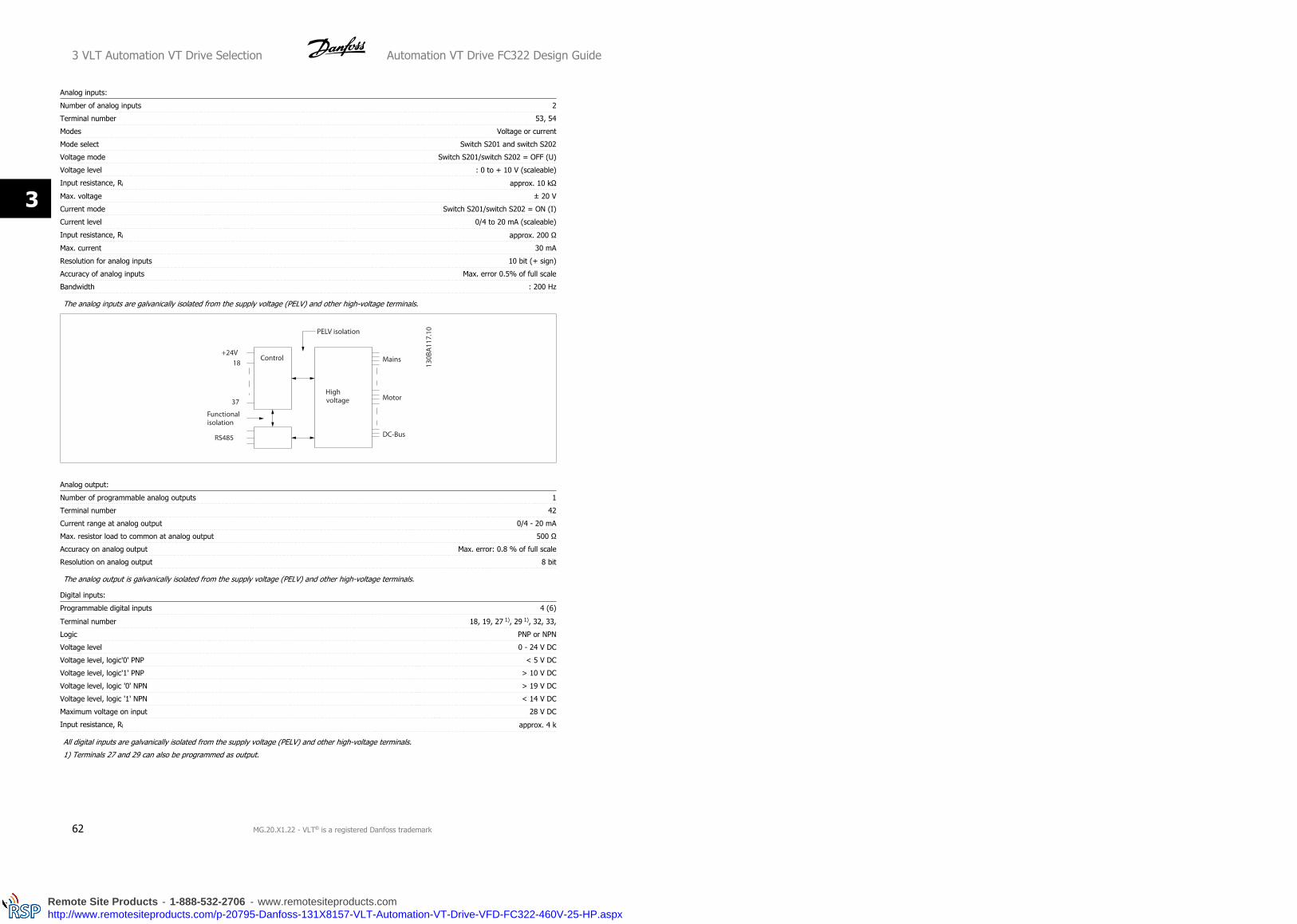
Analog inputs:
Number of analog inputs 2
Terminal number 53, 54
Modes Voltage or current
Mode select Switch S201 and switch S202
Voltage mode Switch S201/switch S202 = OFF (U)
Voltage level : 0 to + 10 V (scaleable)
Input resistance, Ri approx. 10 kΩ
Max. voltage ± 20 V
Current mode Switch S201/switch S202 = ON (I)
Current level 0/4 to 20 mA (scaleable)
Input resistance, Ri approx. 200 Ω
Max. current 30 mA
Resolution for analog inputs 10 bit (+ sign)
Accuracy of analog inputs Max. error 0.5% of full scale
Bandwidth : 200 Hz
The analog inputs are galvanically isolated from the supply voltage (PELV) and other high-voltage terminals.
Analog output:
Number of programmable analog outputs 1
Terminal number 42
Current range at analog output 0/4 - 20 mA
Max. resistor load to common at analog output 500 Ω
Accuracy on analog output Max. error: 0.8 % of full scale
Resolution on analog output 8 bit
The analog output is galvanically isolated from the supply voltage (PELV) and other high-voltage terminals.
Digital inputs:
Programmable digital inputs 4 (6)
Terminal number 18, 19, 27 1), 29 1), 32, 33,
Logic PNP or NPN
Voltage level 0 - 24 V DC
Voltage level, logic'0' PNP < 5 V DC
Voltage level, logic'1' PNP > 10 V DC
Voltage level, logic '0' NPN > 19 V DC
Voltage level, logic '1' NPN < 14 V DC
Maximum voltage on input 28 V DC
Input resistance, Ri approx. 4 k
All digital inputs are galvanically isolated from the supply voltage (PELV) and other high-voltage terminals.
1) Terminals 27 and 29 can also be programmed as output.
3 VLT Automation VT Drive Selection Automation VT Drive FC322 Design Guide
62 MG.20.X1.22 - VLT® is a registered Danfoss trademark
3
Remote Site Products - 1-888-532-2706 - www.remotesiteproducts.comhttp://www.remotesiteproducts.com/p-20795-Danfoss-131X8157-VLT-Automation-VT-Drive-VFD-FC322-460V-25-HP.aspx

Digital output:
Programmable digital/pulse outputs 2
Terminal number 27, 29 1)
Voltage level at digital/frequency output 0 - 24 V
Max. output current (sink or source) 40 mA
Max. load at frequency output 1 kΩ
Max. capacitive load at frequency output 10 nF
Minimum output frequency at frequency output 0 Hz
Maximum output frequency at frequency output 32 kHz
Accuracy of frequency output Max. error: 0.1 % of full scale
Resolution of frequency outputs 12 bit
1) Terminal 27 and 29 can also be programmed as input.
The digital output is galvanically isolated from the supply voltage (PELV) and other high-voltage terminals.
Pulse inputs:
Programmable pulse inputs 2
Terminal number pulse 29, 33
Max. frequency at terminal, 29, 33 110 kHz (Push-pull driven)
Max. frequency at terminal, 29, 33 5 kHz (open collector)
Min. frequency at terminal 29, 33 4 Hz
Voltage level see section on Digital input
Maximum voltage on input 28 V DC
Input resistance, Ri approx. 4 kΩ
Pulse input accuracy (0.1 - 1 kHz) Max. error: 0.1% of full scale
Control card, 24 V DC output:
Terminal number 12, 13
Max. load : 200 mA
The 24 V DC supply is galvanically isolated from the supply voltage (PELV), but has the same potential as the analog and digital inputs and outputs.
Relay outputs:
Programmable relay outputs 2
Relay 01 Terminal number 1-3 (break), 1-2 (make)
Max. terminal load (AC-1)1) on 1-3 (NC), 1-2 (NO) (Resistive load) 240 V AC, 2 A
Max. terminal load (AC-15)1) (Inductive load @ cosφ 0.4) 240 V AC, 0.2 A
Max. terminal load (DC-1)1) on 1-2 (NO), 1-3 (NC) (Resistive load) 60 V DC, 1A
Max. terminal load (DC-13)1) (Inductive load) 24 V DC, 0.1A
Relay 02 Terminal number 4-6 (break), 4-5 (make)
Max. terminal load (AC-1)1) on 4-5 (NO) (Resistive load)2)3) 400 V AC, 2 A
Max. terminal load (AC-15)1) on 4-5 (NO) (Inductive load @ cosφ 0.4) 240 V AC, 0.2 A
Max. terminal load (DC-1)1) on 4-5 (NO) (Resistive load) 80 V DC, 2 A
Max. terminal load (DC-13)1) on 4-5 (NO) (Inductive load) 24 V DC, 0.1A
Max. terminal load (AC-1)1) on 4-6 (NC) (Resistive load) 240 V AC, 2 A
Max. terminal load (AC-15)1) on 4-6 (NC) (Inductive load @ cosφ 0.4) 240 V AC, 0.2A
Max. terminal load (DC-1)1) on 4-6 (NC) (Resistive load) 50 V DC, 2 A
Max. terminal load (DC-13)1) on 4-6 (NC) (Inductive load) 24 V DC, 0.1 A
Min. terminal load on 1-3 (NC), 1-2 (NO), 4-6 (NC), 4-5 (NO) 24 V DC 10 mA, 24 V AC 20 mA
Environment according to EN 60664-1 overvoltage category III/pollution degree 2
1) IEC 60947 part 4 and 5
The relay contacts are galvanically isolated from the rest of the circuit by reinforced isolation (PELV).
2) Overvoltage Category II
3) UL applications 300 V AC 2A
Automation VT Drive FC322 Design Guide 3 VLT Automation VT Drive Selection
MG.20.X1.22 - VLT® is a registered Danfoss trademark 63
3
Remote Site Products - 1-888-532-2706 - www.remotesiteproducts.comhttp://www.remotesiteproducts.com/p-20795-Danfoss-131X8157-VLT-Automation-VT-Drive-VFD-FC322-460V-25-HP.aspx
Control card, 10 V DC output:
Terminal number 50
Output voltage 10.5 V ±0.5 V
Max. load 25 mA
The 10 V DC supply is galvanically isolated from the supply voltage (PELV) and other high-voltage terminals.
Control characteristics:
Resolution of output frequency at 0 - 1000 Hz : +/- 0.003 Hz
System response time (terminals 18, 19, 27, 29, 32, 33) : ≤ 2 ms
Speed control range (open loop) 1:100 of synchronous speed
Speed accuracy (open loop) 30 - 4000 rpm: Maximum error of ±8 rpm
All control characteristics are based on a 4-pole asynchronous motor
Surroundings:
Enclosure type A IP 20/Chassis, IP 21kit/Type 1, IP55/Type12, IP 66
Enclosure type B1/B2 IP 21/Type 1, IP55/Type12, IP 66
Enclosure type B3/B4 IP20/Chassis
Enclosure type C1/C2 IP 21/Type 1, IP55/Type 12, IP66
Enclosure type C3/C4 IP20/Chassis
Enclosure type D1/D2/E1 IP21/Type 1, IP54/Type12
Enclosure type D3/D4/E2 IP00/Chassis
Enclosure kit available ≤ enclosure type A IP21/TYPE 1/IP 4X top
Vibration test enclosure A/B/C 1.0 g
Vibration test enclosure D/E/F 0.7 g
Max. relative humidity 5% - 95%(IEC 721-3-3; Class 3K3 (non-condensing) during operation
Aggressive environment (IEC 721-3-3), uncoated class 3C2
Aggressive environment (IEC 721-3-3), coated class 3C3
Test method according to IEC 60068-2-43 H2S (10 days)
Ambient temperature Max. 50 °C
Derating for high ambient temperature, see section on special conditions
Minimum ambient temperature during full-scale operation 0 °C
Minimum ambient temperature at reduced performance - 10 °C
Temperature during storage/transport -25 - +65/70 °C
Maximum altitude above sea level without derating 1000 m
Maximum altitude above sea level with derating 3000 m
Derating for high altitude, see section on special conditions
EMC standards, Emission EN 61800-3, EN 61000-6-3/4, EN 55011, IEC 61800-3
EMC standards, Immunity
EN 61800-3, EN 61000-6-1/2,
EN 61000-4-2, EN 61000-4-3, EN 61000-4-4, EN 61000-4-5, EN 61000-4-6
See section on special conditions
Control card performance:
Scan interval : 5 ms
Control card, USB serial communication:
USB standard 1.1 (Full speed)
USB plug USB type B “device” plug
Connection to PC is carried out via a standard host/device USB cable.
The USB connection is galvanically isolated from the supply voltage (PELV) and other high-voltage terminals.
The USB connection is not galvanically isolated from protection earth. Use only isolated laptop/PC as connection to the USB connector
on VLT Automation VT Drive or an isolated USB cable/converter.
3 VLT Automation VT Drive Selection Automation VT Drive FC322 Design Guide
64 MG.20.X1.22 - VLT® is a registered Danfoss trademark
3
Remote Site Products - 1-888-532-2706 - www.remotesiteproducts.comhttp://www.remotesiteproducts.com/p-20795-Danfoss-131X8157-VLT-Automation-VT-Drive-VFD-FC322-460V-25-HP.aspx

3.2 Efficiency Efficiency of VLT Automation VT Drive (η VLT)
The load on the frequency converter has little effect on its efficiency. In general, the efficiency is the same at the rated motor frequency fM,N, even if the
motor supplies 100% of the rated shaft torque or only 75%, i.e. in case of part loads.
This also means that the efficiency of the frequency converter does not change even if other U/f characteristics are chosen.
However, the U/f characteristics influence the efficiency of the motor.
The efficiency declines a little when the switching frequency is set to a value of above 5 kHz. The efficiency will also be slightly reduced if the mains
voltage is 480 V, or if the motor cable is longer than 30 m.
Efficiency of the motor (η)MOTOR
The efficiency of a motor connected to the frequency converter depends on magnetising level. In general, the efficiency is just as good as with mains
operation. The efficiency of the motor depends on the type of motor.
In the range of 75-100% of the rated torque, the efficiency of the motor is practically constant, both when it is controlled by the frequency converter
and when it runs directly on mains.
In small motors, the influence from the U/f characteristic on efficiency is marginal. However, in motors from 11 kW and up, the advantages are significant.
In general, the switching frequency does not affect the efficiency of small motors. Motors from 11 kW and up have their efficiency improved (1-2%). This
is because the sine shape of the motor current is almost perfect at high switching frequency.
Efficiency of the system (ηSYSTEM
To calculate the system efficiency, the efficiency of VLT Automation VT Drive (ηVLT) is multiplied by the efficiency of the motor (ηMOTOR):
ηSYSTEM) = η VLT x ηMOTOR
Calculate the efficiency of the system at different loads based on the graph above.
Automation VT Drive FC322 Design Guide 3 VLT Automation VT Drive Selection
MG.20.X1.22 - VLT® is a registered Danfoss trademark 65
3
Remote Site Products - 1-888-532-2706 - www.remotesiteproducts.comhttp://www.remotesiteproducts.com/p-20795-Danfoss-131X8157-VLT-Automation-VT-Drive-VFD-FC322-460V-25-HP.aspx

3.3 Acoustic NoiseThe acoustic noise from the frequency converter comes from three sources:
1. DC intermediate circuit coils.
2. Integral fan.
3. RFI filter choke.
The typical values measured at a distance of 1 m from the unit:
Enclosure At reduced fan speed (50%) [dBA] *** Full fan speed [dBA]
A2 51 60
A3 51 60
A5 54 63
B1 61 67
B2 58 70
B3 59.4 70.5
B4 53 62.8
C1 52 62
C2 55 65
C3 56.4 67.3
C4 - -
D1+D3 74 76
D2+D4 73 74
E1/E2 * 73 74
E1/E2 ** 82 83
F1/F2/F3/F4 78 80
* 315 kW, 380-480 VAC and 450/500 kW, 525-690 VAC only!
** Remaining E1+E2 power sizes.
*** For D, E and F sizes, reduced fan speed is at 87%, measured at 200 V.
3.4 Peak Voltage on MotorWhen a transistor in the inverter bridge switches, the voltage across the motor increases by a du/dt ratio depending on:
- the motor cable (type, cross-section, length screened or unscreened)
- inductance
The natural induction causes an overshoot UPEAK in the motor voltage before it stabilizes itself at a level depending on the voltage in the intermediate
circuit. The rise time and the peak voltage UPEAK affect the service life of the motor. If the peak voltage is too high, especially motors without phase coil
insulation are affected. If the motor cable is short (a few metres), the rise time and peak voltage are lower.
If the motor cable is long (100 m), the rise time and peak voltage increases.
In motors without phase insulation paper or other insulation reinforcement suitable for operation with voltage supply (such as a frequency converter),
fit a sine-wave filter on the output of the frequency converter.
To obtain approximate values for cable lengths and voltages not mentioned below, use the following rules of thumb:
3 VLT Automation VT Drive Selection Automation VT Drive FC322 Design Guide
66 MG.20.X1.22 - VLT® is a registered Danfoss trademark
3
Remote Site Products - 1-888-532-2706 - www.remotesiteproducts.comhttp://www.remotesiteproducts.com/p-20795-Danfoss-131X8157-VLT-Automation-VT-Drive-VFD-FC322-460V-25-HP.aspx
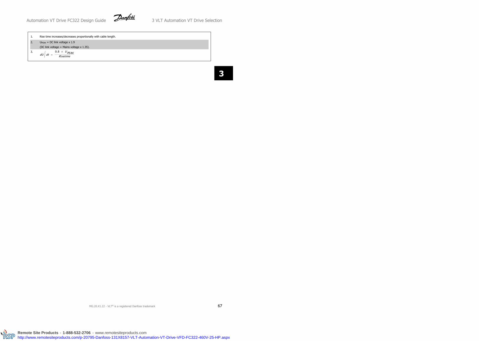
1. Rise time increases/decreases proportionally with cable length.
2. UPEAK = DC link voltage x 1.9
(DC link voltage = Mains voltage x 1.35).
3.dU / dt =
0.8 × UPEAKRisetime
Automation VT Drive FC322 Design Guide 3 VLT Automation VT Drive Selection
MG.20.X1.22 - VLT® is a registered Danfoss trademark 67
3
Remote Site Products - 1-888-532-2706 - www.remotesiteproducts.comhttp://www.remotesiteproducts.com/p-20795-Danfoss-131X8157-VLT-Automation-VT-Drive-VFD-FC322-460V-25-HP.aspx
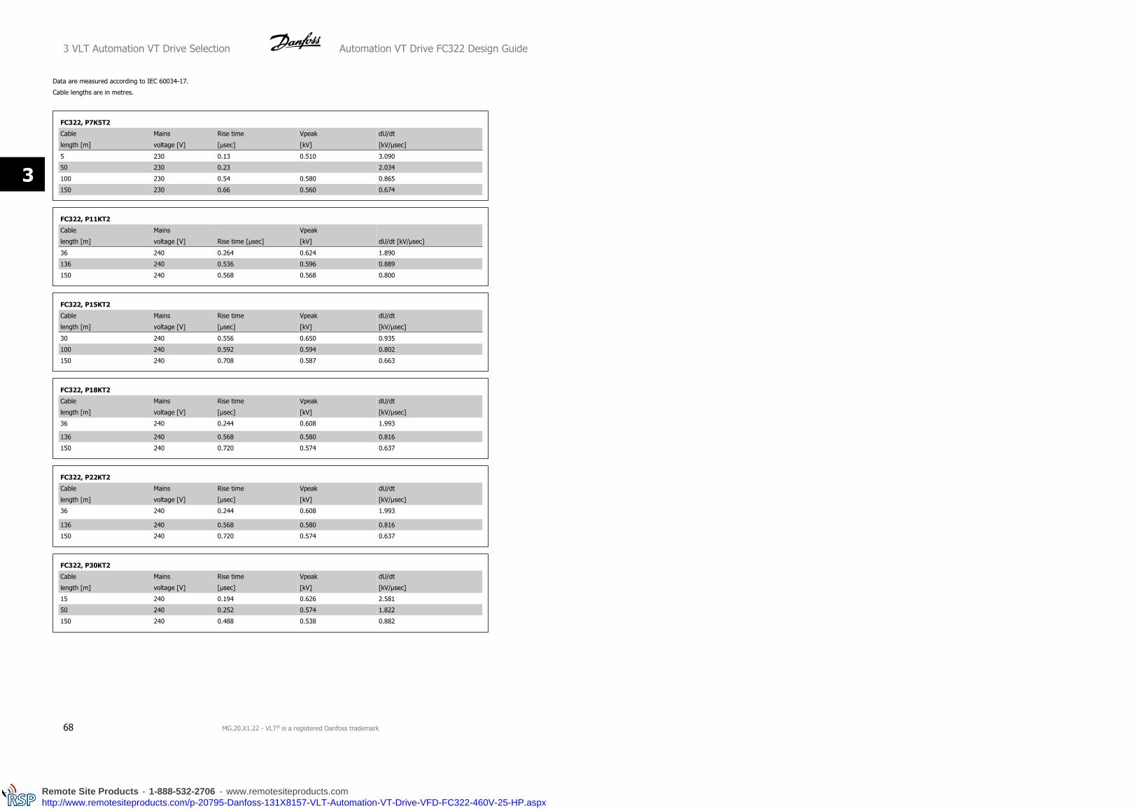
Data are measured according to IEC 60034-17.
Cable lengths are in metres.
FC322, P7K5T2
Cable
length [m]
Mains
voltage [V]
Rise time
[μsec]
Vpeak
[kV]
dU/dt
[kV/μsec]
5 230 0.13 0.510 3.090
50 230 0.23 2.034
100 230 0.54 0.580 0.865
150 230 0.66 0.560 0.674
FC322, P11KT2
Cable
length [m]
Mains
voltage [V] Rise time [μsec]
Vpeak
[kV] dU/dt [kV/μsec]
36 240 0.264 0.624 1.890
136 240 0.536 0.596 0.889
150 240 0.568 0.568 0.800
FC322, P15KT2
Cable
length [m]
Mains
voltage [V]
Rise time
[μsec]
Vpeak
[kV]
dU/dt
[kV/μsec]
30 240 0.556 0.650 0.935
100 240 0.592 0.594 0.802
150 240 0.708 0.587 0.663
FC322, P18KT2
Cable
length [m]
Mains
voltage [V]
Rise time
[μsec]
Vpeak
[kV]
dU/dt
[kV/μsec]
36 240 0.244 0.608 1.993
136 240 0.568 0.580 0.816
150 240 0.720 0.574 0.637
FC322, P22KT2
Cable
length [m]
Mains
voltage [V]
Rise time
[μsec]
Vpeak
[kV]
dU/dt
[kV/μsec]
36 240 0.244 0.608 1.993
136 240 0.568 0.580 0.816
150 240 0.720 0.574 0.637
FC322, P30KT2
Cable
length [m]
Mains
voltage [V]
Rise time
[μsec]
Vpeak
[kV]
dU/dt
[kV/μsec]
15 240 0.194 0.626 2.581
50 240 0.252 0.574 1.822
150 240 0.488 0.538 0.882
3 VLT Automation VT Drive Selection Automation VT Drive FC322 Design Guide
68 MG.20.X1.22 - VLT® is a registered Danfoss trademark
3
Remote Site Products - 1-888-532-2706 - www.remotesiteproducts.comhttp://www.remotesiteproducts.com/p-20795-Danfoss-131X8157-VLT-Automation-VT-Drive-VFD-FC322-460V-25-HP.aspx

FC322, P37KT2
Cable
length [m]
Mains
voltage [V]
Rise time
[μsec]
Vpeak
[kV]
dU/dt
[kV/μsec]
30 240 0.300 0.598 1.594
100 240 0.536 0.566 0.844
150 240 0.776 0.546 0.562
FC322, P45KT2
Cable
length [m]
Mains
voltage [V]
Rise time
[μsec]
Vpeak
[kV]
dU/dt
[kV/μsec]
30 240 0.300 0.598 1.594
100 240 0.536 0.566 0.844
150 240 0.776 0.546 0.562
FC322, P1K5T4
Cable
length [m]
Mains
voltage [V]
Rise time
[μsec]
Vpeak
[kV]
dU/dt
[kV/μsec]
5 690 0.640 0.690 0.862
50 985 0.470 0.985
150 1045 0.760 1.045 0.947
FC322, P4K0T4
Cable
length [m]
Mains
voltage [V]
Rise time
[μsec]
Vpeak
[kV]
dU/dt
[kV/μsec]
5 400 0.172 0.890 4.156
50 400 0.310 2.564
150 400 0.370 1.190 1.770
FC322, P7K5T4
Cable
length [m]
Mains
voltage [V]
Rise time
[μsec]
Vpeak
[kV]
dU/dt
[kV/μsec]
5 500 0.04755 0.739 8.035
50 500 0.207 4.548
150 500 0.6742 1.030 2.828
FC322, P11KT4
Cable
length [m]
Mains
voltage [V]
Rise time
[μsec]
Vpeak
[kV]
dU/dt
[kV/μsec]
15 480 0.192 1.300 5.416
100 480 0.612 1.300 1.699
150 480 0.512 1.290 2.015
FC322, P15KT4
Cable
length [m]
Mains
voltage [V]
Rise time
[μsec]
Vpeak
[kV]
dU/dt
[kV/μsec]
36 480 0.396 1.210 2.444
100 480 0.844 1.230 1.165
150 480 0.696 1.160 1.333
Automation VT Drive FC322 Design Guide 3 VLT Automation VT Drive Selection
MG.20.X1.22 - VLT® is a registered Danfoss trademark 69
3
Remote Site Products - 1-888-532-2706 - www.remotesiteproducts.comhttp://www.remotesiteproducts.com/p-20795-Danfoss-131X8157-VLT-Automation-VT-Drive-VFD-FC322-460V-25-HP.aspx

FC322, P18KT4
Cable
length [m]
Mains
voltage [V]
Rise time
[μsec]
Vpeak
[kV]
dU/dt
[kV/μsec]
36 480 0.396 1.210 2.444
100 480 0.844 1.230 1.165
150 480 0.696 1.160 1.333
FC322, P22KT4
Cable
length [m]
Mains
voltage [V]
Rise time
[μsec]
Vpeak
[kV]
dU/dt
[kV/μsec]
36 480 0.312 2.846
100 480 0.556 1.250 1.798
150 480 0.608 1.230 1.618
FC322, P30KT4
Cable
length [m]
Mains
voltage [V]
Rise time
[μsec]
Vpeak
[kV]
dU/dt
[kV/μsec]
15 480 0.288 3.083
100 480 0.492 1.230 2.000
150 480 0.468 1.190 2.034
FC322, P37KT4
Cable
length [m]
Mains
voltage
Rise time
[μsec]
Vpeak
[kV]
dU/dt
[kV/μsec]
5 480 0.368 1.270 2.853
50 480 0.536 1.260 1.978
100 480 0.680 1.240 1.426
150 480 0.712 1.200 1.334
FC322, P45KT4
Cable
length [m]
Mains
voltage [V]
Rise time
[μsec]
Vpeak
[kV]
dU/dt
[kV/μsec]
5 480 0.368 1.270 2.853
50 480 0.536 1.260 1.978
100 480 0.680 1.240 1.426
150 480 0.712 1.200 1.334
FC322, P55KT4
Cable
length [m]
Mains
voltage [V]
Rise time
[μsec]
Vpeak
[kV]
dU/dt
[kV/μsec]
15 480 0.256 1.230 3.847
50 480 0.328 1.200 2.957
100 480 0.456 1.200 2.127
150 480 0.960 1.150 1.052
FC322, P75KT4
Cable
length [m]
Mains
voltage [V]
Rise time
[μsec]
Vpeak
[kV]
dU/dt
[kV/μsec]
5 480 0.371 1.170 2.523
3 VLT Automation VT Drive Selection Automation VT Drive FC322 Design Guide
70 MG.20.X1.22 - VLT® is a registered Danfoss trademark
3
Remote Site Products - 1-888-532-2706 - www.remotesiteproducts.comhttp://www.remotesiteproducts.com/p-20795-Danfoss-131X8157-VLT-Automation-VT-Drive-VFD-FC322-460V-25-HP.aspx

FC322, P90KT4
Cable
length [m]
Mains
voltage [V]
Rise time
[μsec]
Vpeak
[kV]
dU/dt
[kV/μsec]
5 480 0.371 1.170 2.523
High Power Range:
FC322, P110 - P250, T4
Cable
length [m]
Mains
voltage [V]
Rise time
[μsec]
Vpeak
[kV]
dU/dt
[kV/μsec]
30 400 0.34 1.040 2.447
FC322, P315 - P1M0, T4
Cable
length [m]
Mains
voltage [V]
Rise time
[μsec]
Vpeak
[kV]
dU/dt
[kV/μsec]
30 500 0.71 1.165 1.389
30 400 0.61 0.942 1.233
FC322, P110 - P400, T7
Cable
length [m]
Mains
voltage [V]
Rise time
[μsec]
Vpeak
[kV]
dU/dt
[kV/μsec]
30 690 0.38 1.513 3.304
30 575 0.23 1.313 2.750
30 690 1) 1.72 1.329 0.640
1) With Danfoss dU/dt filter.
FC322, P450 - P1M2, T7
Cable
length [m]
Mains
voltage [V]
Rise time
[μsec]
Vpeak
[kV]
dU/dt
[kV/μsec]
30 690 0.57 1.611 2.261
30 575 0.25 2.510
30 690 1) 1.13 1.629 1.150
1) With Danfoss dU/dt filter.
Automation VT Drive FC322 Design Guide 3 VLT Automation VT Drive Selection
MG.20.X1.22 - VLT® is a registered Danfoss trademark 71
3
Remote Site Products - 1-888-532-2706 - www.remotesiteproducts.comhttp://www.remotesiteproducts.com/p-20795-Danfoss-131X8157-VLT-Automation-VT-Drive-VFD-FC322-460V-25-HP.aspx
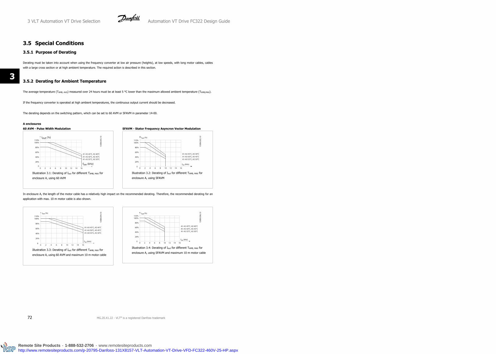
3.5 Special Conditions
3.5.1 Purpose of Derating
Derating must be taken into account when using the frequency converter at low air pressure (heights), at low speeds, with long motor cables, cables
with a large cross section or at high ambient temperature. The required action is described in this section.
3.5.2 Derating for Ambient Temperature
The average temperature (TAMB, AVG) measured over 24 hours must be at least 5 °C lower than the maximum allowed ambient temperature (TAMB,MAX).
If the frequency converter is operated at high ambient temperatures, the continuous output current should be decreased.
The derating depends on the switching pattern, which can be set to 60 AVM or SFAVM in parameter 14-00.
A enclosures
60 AVM - Pulse Width Modulation
Illustration 3.1: Derating of Iout for different TAMB, MAX for
enclosure A, using 60 AVM
SFAVM - Stator Frequency Asyncron Vector Modulation
Illustration 3.2: Derating of Iout for different TAMB, MAX for
enclosure A, using SFAVM
In enclosure A, the length of the motor cable has a relatively high impact on the recommended derating. Therefore, the recommended derating for an
application with max. 10 m motor cable is also shown.
Illustration 3.3: Derating of Iout for different TAMB, MAX for
enclosure A, using 60 AVM and maximum 10 m motor cable
Illustration 3.4: Derating of Iout for different TAMB, MAX for
enclosure A, using SFAVM and maximum 10 m motor cable
3 VLT Automation VT Drive Selection Automation VT Drive FC322 Design Guide
72 MG.20.X1.22 - VLT® is a registered Danfoss trademark
3
Remote Site Products - 1-888-532-2706 - www.remotesiteproducts.comhttp://www.remotesiteproducts.com/p-20795-Danfoss-131X8157-VLT-Automation-VT-Drive-VFD-FC322-460V-25-HP.aspx
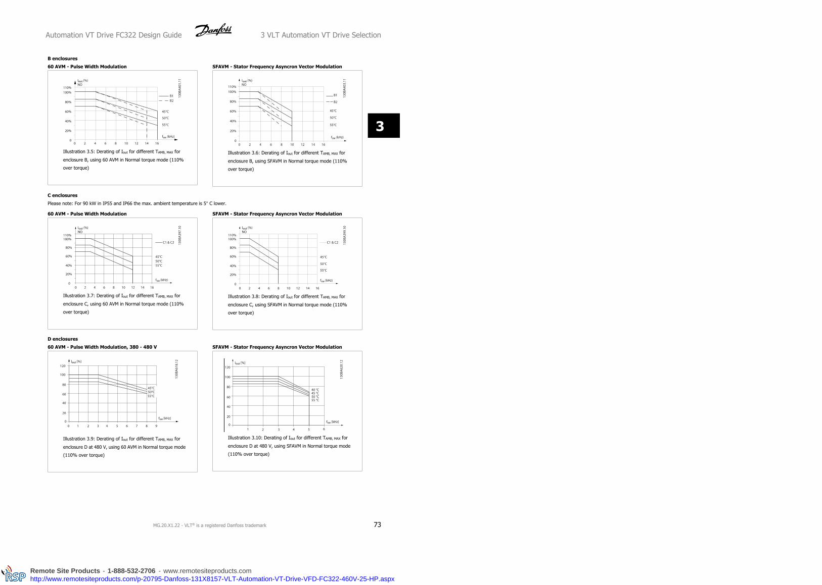
B enclosures
60 AVM - Pulse Width Modulation
Illustration 3.5: Derating of Iout for different TAMB, MAX for
enclosure B, using 60 AVM in Normal torque mode (110%
over torque)
SFAVM - Stator Frequency Asyncron Vector Modulation
Illustration 3.6: Derating of Iout for different TAMB, MAX for
enclosure B, using SFAVM in Normal torque mode (110%
over torque)
C enclosures
Please note: For 90 kW in IP55 and IP66 the max. ambient temperature is 5° C lower.
60 AVM - Pulse Width Modulation
Illustration 3.7: Derating of Iout for different TAMB, MAX for
enclosure C, using 60 AVM in Normal torque mode (110%
over torque)
SFAVM - Stator Frequency Asyncron Vector Modulation
Illustration 3.8: Derating of Iout for different TAMB, MAX for
enclosure C, using SFAVM in Normal torque mode (110%
over torque)
D enclosures
60 AVM - Pulse Width Modulation, 380 - 480 V
Illustration 3.9: Derating of Iout for different TAMB, MAX for
enclosure D at 480 V, using 60 AVM in Normal torque mode
(110% over torque)
SFAVM - Stator Frequency Asyncron Vector Modulation
Illustration 3.10: Derating of Iout for different TAMB, MAX for
enclosure D at 480 V, using SFAVM in Normal torque mode
(110% over torque)
Automation VT Drive FC322 Design Guide 3 VLT Automation VT Drive Selection
MG.20.X1.22 - VLT® is a registered Danfoss trademark 73
3
Remote Site Products - 1-888-532-2706 - www.remotesiteproducts.comhttp://www.remotesiteproducts.com/p-20795-Danfoss-131X8157-VLT-Automation-VT-Drive-VFD-FC322-460V-25-HP.aspx

60 AVM - Pulse Width Modulation, 525 - 690 V (except P400)
Illustration 3.11: Derating of Iout for different TAMB, MAX for
enclosure D at 690 V, using 60 AVM in Normal torque mode
(110% over torque). Note: not valid for P400.
SFAVM - Stator Frequency Asyncron Vector Modulation
Illustration 3.12: Derating of Iout for different TAMB, MAX for
enclosure D at 690 V, using SFAVM in Normal torque mode
(110% over torque). Note: not valid for P400.
60 AVM - Pulse Width Modulation, 525 - 690 V, P400
Illustration 3.13: Derating of Iout for different TAMB, MAX for
enclosure D at 690 V, using 60 AVM in Normal torque mode
(110% over torque). Note: P400 only.
SFAVM - Stator Frequency Asyncron Vector Modulation
Illustration 3.14: Derating of Iout for different TAMB, MAX for
enclosure D at 690 V, using SFAVM in Normal torque mode
(110% over torque). Note: P400 only.
E and F enclosures
60 AVM - Pulse Width Modulation, 380 - 480 V
Illustration 3.15: Derating of Iout for different TAMB, MAX for
enclosure E at 480 V, using 60 AVM in Normal torque mode
(110% over torque)
SFAVM - Stator Frequency Asyncron Vector Modulation
Illustration 3.16: Derating of Iout for different TAMB, MAX for
enclosure E and F at 480 V, using SFAVM in Normal torque
mode (110% over torque)
3 VLT Automation VT Drive Selection Automation VT Drive FC322 Design Guide
74 MG.20.X1.22 - VLT® is a registered Danfoss trademark
3
Remote Site Products - 1-888-532-2706 - www.remotesiteproducts.comhttp://www.remotesiteproducts.com/p-20795-Danfoss-131X8157-VLT-Automation-VT-Drive-VFD-FC322-460V-25-HP.aspx

60 AVM - Pulse Width Modulation, 525 - 690 V
Illustration 3.17: Derating of Iout for different TAMB, MAX for
enclosure E and F at 690 V, using 60 AVM in Normal torque
mode (110% over torque).
SFAVM - Stator Frequency Asyncron Vector Modulation
Illustration 3.18: Derating of Iout for different TAMB, MAX for
enclosure E and F at 690 V, using SFAVM in Normal torque
mode (110% over torque).
3.5.3 Derating for Low Air Pressure
The cooling capability of air is decreased at lower air pressure.
Below 1000 m altitude no derating is necessary but above 1000 m the ambient temperature (TAMB) or max. output current (Iout) should be derated in
accordance with the shown diagram.
Illustration 3.19: Derating of output current versus altitude at TAMB, MAX for frame sizes A, B and C. At altitudes above 2 km, please contact
Danfoss Drives regarding PELV.
An alternative is to lower the ambient temperature at high altitudes and thereby ensure 100% output current at high altitudes. As an example of how to
read the graph, the situation at 2 km is elaborated. At a temperature of 45° C (TAMB, MAX - 3.3 K), 91% of the rated output current is available. At a
temperature of 41.7° C, 100% of the rated output current is available.
Automation VT Drive FC322 Design Guide 3 VLT Automation VT Drive Selection
MG.20.X1.22 - VLT® is a registered Danfoss trademark 75
3
Remote Site Products - 1-888-532-2706 - www.remotesiteproducts.comhttp://www.remotesiteproducts.com/p-20795-Danfoss-131X8157-VLT-Automation-VT-Drive-VFD-FC322-460V-25-HP.aspx

Derating of output current versus altitude at TAMB, MAX for frame sizes D, E and F.
3.5.4 Derating for Running at Low Speed
When a motor is connected to a frequency converter, it is necessary to check that the cooling of the motor is adequate.
The level of heating depends on the load on the motor, as well as the operating speed and time.
Constant torque applications (CT mode)
A problem may occur at low RPM values in constant torque applications. In a constant torque application s a motor may over-heat at low speeds due to
less cooling air from the motor integral fan.
Therefore, if the motor is to be run continuously at an RPM value lower than half of the rated value, the motor must be supplied with additional air-cooling
(or a motor designed for this type of operation may be used).
An alternative is to reduce the load level of the motor by choosing a larger motor. However, the design of the frequency converter puts a limit to the
motor size.
Variable (Quadratic) torque applications (VT)
In VT applications such as centrifugal pumps and fans, where the torque is proportional to the square of the speed and the power is proportional to the
cube of the speed, there is no need for additional cooling or de-rating of the motor.
In the graphs shown below, the typical VT curve is below the maximum torque with de-rating and maximum torque with forced cooling at all speeds.
3 VLT Automation VT Drive Selection Automation VT Drive FC322 Design Guide
76 MG.20.X1.22 - VLT® is a registered Danfoss trademark
3
Remote Site Products - 1-888-532-2706 - www.remotesiteproducts.comhttp://www.remotesiteproducts.com/p-20795-Danfoss-131X8157-VLT-Automation-VT-Drive-VFD-FC322-460V-25-HP.aspx

Maximum Load for a Standard Motor at 40 °C driven by a frequency converter type VLT FCxxx
Legend: Typical torque at VT load •••Max torque with forced cooling ‒‒‒‒‒Max torque
Note 1) Over-syncronous speed operation will result in the available motor torque decreasing inversely proportional with the increase in speed. This
must be considered during the design phase to avoid over-loading of the motor.
3.5.5 Derating for Installing Long Motor Cables or Cables with Larger Cross-Section
NB!
Applicable for drives up to 90 kW only.
The maximum cable length for this frequency converter is 300 m unscreened and 150 m screened cable.
The frequency converter has been designed to work using a motor cable with a rated cross-section. If a cable with a larger cross-section is used, reduce
the output current by 5% for every step the cross-section is increased.
(Increased cable cross-section leads to increased capacity to earth, and thus an increased earth leakage current).
3.5.6 Automatic Adaptations to Ensure Performance
The frequency converter constantly checks for critical levels of internal temperature, load current, high voltage on the intermediate circuit and low motor
speeds. As a response to a critical level, the frequency converter can adjust the switching frequency and / or change the switching pattern in order to
ensure the performance of the frequency converter. The capability to automatically reduce the output current extends the acceptable operating conditions
even further.
3.6 Options and AccessoriesDanfoss offers a wide range of options and accessories for the frequency converters.
3.6.1 Mounting of Option Modules in Slot B
The power to the frequency converter must be disconnected.
For A2 and A3 enclosures:
• Remove the LCP (Local Control Panel), the terminal cover, and the LCP frame from the frequency converter.
• Fit the MCB10x option card into slot B.
Automation VT Drive FC322 Design Guide 3 VLT Automation VT Drive Selection
MG.20.X1.22 - VLT® is a registered Danfoss trademark 77
3
Remote Site Products - 1-888-532-2706 - www.remotesiteproducts.comhttp://www.remotesiteproducts.com/p-20795-Danfoss-131X8157-VLT-Automation-VT-Drive-VFD-FC322-460V-25-HP.aspx

• Connect the control cables and relieve the cable by the enclosed cable strips.
Remove the knock out in the extended LCP frame delivered in the option set, so that the option will fit under the extended LCP frame.
• Fit the extended LCP frame and terminal cover.
• Fit the LCP or blind cover in the extended LCP frame.
• Connect power to the frequency converter.
• Set up the input/output functions in the corresponding parameters, as mentioned in the section General Technical Data.
3 VLT Automation VT Drive Selection Automation VT Drive FC322 Design Guide
78 MG.20.X1.22 - VLT® is a registered Danfoss trademark
3
Remote Site Products - 1-888-532-2706 - www.remotesiteproducts.comhttp://www.remotesiteproducts.com/p-20795-Danfoss-131X8157-VLT-Automation-VT-Drive-VFD-FC322-460V-25-HP.aspx

For B1, B2, C1 and C2 enclosures:
• Remove the LCP and the LCP cradle
• Fit the MCB 10x option card into slot B
• Connect the control cables and relieve the cable by the enclosed cable strips
• Fit the cradle
• Fit the LCP
A2, A3 and B3 enclosures A5, B1, B2, B4, C1, C2, C3 and C4 enclosures
Automation VT Drive FC322 Design Guide 3 VLT Automation VT Drive Selection
MG.20.X1.22 - VLT® is a registered Danfoss trademark 79
3
Remote Site Products - 1-888-532-2706 - www.remotesiteproducts.comhttp://www.remotesiteproducts.com/p-20795-Danfoss-131X8157-VLT-Automation-VT-Drive-VFD-FC322-460V-25-HP.aspx

3.6.2 General Purpose Input Output Module MCB 101
MCB 101 is used for extension of the number of digital and analog inputs
and outputs of the VLT Automation VT Drive.
Contents: MCB 101 must be fitted into slot B in the VLT Auto-
mation VT Drive.
• MCB 101 option module
• Extended LCP frame
• Terminal cover
Galvanic Isolation in the MCB 101
Digital/analog inputs are galvanically isolated from other inputs/outputs on the MCB 101 and in the control card of the drive. Digital/analog outputs in
the MCB 101 are galvanically isolated from other inputs/outputs on the MCB 101, but not from these on the control card of the drive.
If the digital inputs 7, 8 or 9 are to be switched by use of the internal 24 V power supply (terminal 9) the connection between terminal 1 and 5 which is
illustrated in the drawing has to be established.
Illustration 3.20: Principle Diagram
3 VLT Automation VT Drive Selection Automation VT Drive FC322 Design Guide
80 MG.20.X1.22 - VLT® is a registered Danfoss trademark
3
Remote Site Products - 1-888-532-2706 - www.remotesiteproducts.comhttp://www.remotesiteproducts.com/p-20795-Danfoss-131X8157-VLT-Automation-VT-Drive-VFD-FC322-460V-25-HP.aspx

3.6.3 Digital inputs - Terminal X30/1-4
Parameters for set-up: 5-16, 5-17 and 5-18
Number of digital
inputs
Voltage level Voltage levels Tolerance Max. Input impedance
3 0-24 V DC PNP type:
Common = 0 V
Logic “0”: Input < 5 V DC
Logic “0”: Input > 10 V DC
NPN type:
Common = 24 V
Logic “0”: Input > 19 V DC
Logic “0”: Input < 14 V DC
± 28 V continuous
± 37 V in minimum 10 sec.
Approx. 5 k ohm
3.6.4 Analog Voltage inputs - Terminal X30/10-12
Parameters for set-up: 6-3*, 6-4* and 16-76
Number of analog voltage inputs Standardized input signal Tolerance Resolution Max. Input impedance
2 0-10 V DC ± 20 V continuously 10 bits Approx. 5 K ohm
3.6.5 Digital Outputs - Terminal X30/5-7
Parameters for set-up: 5-32 and 5-33
Number of digital outputs Output level Tolerance Max.impedance
2 0 or 24 V DC ± 4 V ≥ 600 ohm
3.6.6 Analog Outputs - Terminal X30/5+8
Parameters for set-up: 6-6* and 16-77
Number of analog outputs Output signal level Tolerance Max.impedance
1 0/4 - 20 mA ± 0.1 mA < 500 ohm
Automation VT Drive FC322 Design Guide 3 VLT Automation VT Drive Selection
MG.20.X1.22 - VLT® is a registered Danfoss trademark 81
3
Remote Site Products - 1-888-532-2706 - www.remotesiteproducts.comhttp://www.remotesiteproducts.com/p-20795-Danfoss-131X8157-VLT-Automation-VT-Drive-VFD-FC322-460V-25-HP.aspx

3.6.7 Relay Option MCB 105
The MCB 105 option includes 3 pieces of SPDT contacts and must be fitted into option slot B.
Electrical Data:
Max terminal load (AC-1) 1) (Resistive load) 240 V AC 2A
Max terminal load (AC-15 ) 1) (Inductive load @ cosφ 0.4) 240 V AC 0.2 A
Max terminal load (DC-1) 1) (Resistive load) 24 V DC 1 A
Max terminal load (DC-13) 1) (Inductive load) 24 V DC 0.1 A
Min terminal load (DC) 5 V 10 mA
Max switching rate at rated load/min load 6 min-1/20 sec-1
1) IEC 947 part 4 and 5
When the relay option kit is ordered separately the kit includes:
• Relay Module MCB 105
• Extended LCP frame and enlarged terminal cover
• Label for covering access to switches S201, S202 and S801
• Cable strips for fastening cables to relay module
A2-A3-B3 A5-B1-B2-B4-C1-C2-C3-C4
1) IMPORTANT! The label MUST be placed on the LCP frame as shown (UL approved).
3 VLT Automation VT Drive Selection Automation VT Drive FC322 Design Guide
82 MG.20.X1.22 - VLT® is a registered Danfoss trademark
3
Remote Site Products - 1-888-532-2706 - www.remotesiteproducts.comhttp://www.remotesiteproducts.com/p-20795-Danfoss-131X8157-VLT-Automation-VT-Drive-VFD-FC322-460V-25-HP.aspx

Warning Dual supply
How to add the MCB 105 option:
• See mounting instructions in the beginning of section Options and Accessories
• The power to the live part connections on relay terminals must be disconnected.
• Do not mix live parts (high voltage) with control signals (PELV).
• Select the relay functions in par. 5-40 Function Relay [6-8], par. 5-41 On Delay, Relay [6-8] and par. 5-42 Off Delay, Relay [6-8].
NB! (Index [6] is relay 7, index [7] is relay 8, and index [8] is relay 9)
Automation VT Drive FC322 Design Guide 3 VLT Automation VT Drive Selection
MG.20.X1.22 - VLT® is a registered Danfoss trademark 83
3
Remote Site Products - 1-888-532-2706 - www.remotesiteproducts.comhttp://www.remotesiteproducts.com/p-20795-Danfoss-131X8157-VLT-Automation-VT-Drive-VFD-FC322-460V-25-HP.aspx

Do not combine low voltage parts and PELV systems.
3.6.8 24 V Back-Up Option MCB 107 (Option D)
External 24 V DC Supply
An external 24 V DC supply can be installed for low-voltage supply to the control card and any option card installed. This enables full operation of the
LCP (including the parameter setting) and field busses without mains supplied to the power section.
External 24 V DC supply specification:
Input voltage range 24 V DC ±15 % (max. 37 V in 10 s)
Max. input current 2.2 A
Average input current for the frequency converter 0.9 A
Max cable length 75 m
Input capacitance load < 10 uF
Power-up delay < 0.6 s
The inputs are protected.
Terminal numbers:
Terminal 35: - external 24 V DC supply.
Terminal 36: + external 24 V DC supply.
Follow these steps:
1. Remove the LCP or Blind Cover
2. Remove the Terminal Cover
3. Remove the Cable De-coupling Plate and the plastic cover un-
derneath
4. Insert the 24 V DC Backup External Supply Option in the Option
Slot
5. Mount the Cable De-coupling Plate
6. Attach the Terminal Cover and the LCP or Blind Cover.
When MCB 107, 24 V backup option is supplying the control circuit, the
internal 24 V supply is automatically disconnected.
Illustration 3.21: Connection to 24 V backup supplier (A2-
A3).
3 VLT Automation VT Drive Selection Automation VT Drive FC322 Design Guide
84 MG.20.X1.22 - VLT® is a registered Danfoss trademark
3
Remote Site Products - 1-888-532-2706 - www.remotesiteproducts.comhttp://www.remotesiteproducts.com/p-20795-Danfoss-131X8157-VLT-Automation-VT-Drive-VFD-FC322-460V-25-HP.aspx

Illustration 3.22: Connection to 24 V backup supplier (A5-
C2).
Automation VT Drive FC322 Design Guide 3 VLT Automation VT Drive Selection
MG.20.X1.22 - VLT® is a registered Danfoss trademark 85
3
Remote Site Products - 1-888-532-2706 - www.remotesiteproducts.comhttp://www.remotesiteproducts.com/p-20795-Danfoss-131X8157-VLT-Automation-VT-Drive-VFD-FC322-460V-25-HP.aspx

3.6.9 Analog I/O Option MCB 109
The Analog I/O card is supposed to be used in e.g. the following cases:
• Providing battery back-up of clock function on control card
• As general extension of analog I/O selection available on control card, e.g. for multi-zone control with three pressure transmitters
• Turning frequency converter into de-central I/O block supporting Building Management System with inputs for sensors and outputs for operating
dampers and valve actuators
• Support Extended PID controllers with I/Os for set point inputs, transmitter/sensor inputs and outputs for actuators.
Illustration 3.23: Principle diagram for Analog I/O mounted in frequency converter.
Analog I/O configuration
3 x Analog Inputs, capable of handling following:
• 0 - 10 VDC
OR
• 0-20 mA (voltage input 0-10V) by mounting a 510Ω resistor across terminals (see NB!)
• 4-20 mA (voltage input 2-10V) by mounting a 510Ω resistor across terminals (see NB)
• Ni1000 temperature sensor of 1000 Ω at 0° C. Specifications according to DIN43760
• Pt1000 temperature sensor of 1000 Ω at 0° C. Specifications according to IEC 60751
3 x Analog Outputs supplying 0-10 VDC.
3 VLT Automation VT Drive Selection Automation VT Drive FC322 Design Guide
86 MG.20.X1.22 - VLT® is a registered Danfoss trademark
3
Remote Site Products - 1-888-532-2706 - www.remotesiteproducts.comhttp://www.remotesiteproducts.com/p-20795-Danfoss-131X8157-VLT-Automation-VT-Drive-VFD-FC322-460V-25-HP.aspx

NB!
Please note the values available within the different standard groups of resistors:
E12: Closest standard value is 470Ω, creating an input of 449.9Ω and 8.997V.
E24: Closest standard value is 510Ω, creating an input of 486.4Ω and 9.728V.
E48: Closest standard value is 511Ω, creating an input of 487.3Ω and 9.746V.
E96: Closest standard value is 523Ω, creating an input of 498.2Ω and 9.964V.
Analog inputs - terminal X42/1-6
Parameter group for read out: 18-3*. See also Programming Guide.
Parameter groups for set-up: 26-0*, 26-1*, 26-2* and 26-3*. See also Programming Guide.
3 x Analog inputs Operating range Resolution Accuracy Sampling Max load Impedance
Used as
temperature
sensor input
-50 to +150 °C 11 bits -50 °C
±1 Kelvin
+150 °C
±2 Kelvin
3 Hz - -
Used as
voltage input0 - 10 VDC 10 bits
0.2% of full
scale at cal.
temperature
2.4 Hz+/- 20 V
continuously
Approximately
5 kΩ
When used for voltage, analog inputs are scalable by parameters for each input.
When used for temperature sensor, analog inputs scaling is preset to necessary signal level for specified temperature span.
When analog inputs are used for temperature sensors, it is possible to read out feedback value in both °C and °F.
When operating with temperature sensors, maximum cable length to connect sensors is 80 m non-screened / non-twisted wires.
Analog outputs - terminal X42/7-12
Parameter group for read out and write: 18-3*. See also Programming Guide
Parameter groups for set-up: 26-4*, 26-5* and 26-6*. See also Programming Guide
3 x Analog outputs Output signal level Resolution Linearity Max load
Volt 0-10 VDC 11 bits 1% of full scale 1 mA
Analog outputs are scalable by parameters for each output.
The function assigned is selectable via a parameter and have same options as for analog outputs on control card.
For a more detailed description of parameters, please refer to the Programming Guide.
Real-time clock (RTC) with back-up
The data format of RTC includes year, month, date, hour, minutes and weekday.
Accuracy of clock is better than ± 20 ppm at 25 °C.
The built-in lithium back-up battery lasts on average for minimum 0 years, when frequency converter is operating at 40 °C ambient temperature. If battery
pack back-up fails, analog I/O option must be exchanged.
Automation VT Drive FC322 Design Guide 3 VLT Automation VT Drive Selection
MG.20.X1.22 - VLT® is a registered Danfoss trademark 87
3
Remote Site Products - 1-888-532-2706 - www.remotesiteproducts.comhttp://www.remotesiteproducts.com/p-20795-Danfoss-131X8157-VLT-Automation-VT-Drive-VFD-FC322-460V-25-HP.aspx

3.6.10 Extended Cascade Controller MCO 101 and Advanced Cascade Controller, MCO 102
Cascade control is a common control system used to control parallel pumps or fans in an energy efficient way.
The Cascade Controller option provides the capability to control multiple pumps configured in parallel in a way that makes them appear as a single larger
pump.
When using Cascade Controllers, the individual pumps are automatically turned on (staged) and turned off (de-staged) as needed in order to satisfy the
required system output for flow or pressure. The speed of pumps connected to VLT Automation VT Drive is also controlled to provide a continuous range
of system output.
Illustration 3.24: Cascade control of multiple pumps
The Cascade Controllers are optional hardware and software components that can be added to the VLT Automation VT Drive. It consists of an option
board containing 3 relays that is installed in the B option location on the Drive. Once options are installed the parameters needed to support the Cascade
Controller functions will be available through the control panel in the 27-** parameter group. The Extended Cascade Controller offers more functionality
than the Basic Cascade Controller. It can be used to extend the Basic Cascade with 3 relays and even to 8 relays with the Advanced Cascade Control card
installed.
While the Cascade controller is designed for pumping applications and this document describes the cascade controller for this application, it is also possible
to use the Cascade Controllers for any application requiring multiple motors configured in parallel.
3 VLT Automation VT Drive Selection Automation VT Drive FC322 Design Guide
88 MG.20.X1.22 - VLT® is a registered Danfoss trademark
3
Remote Site Products - 1-888-532-2706 - www.remotesiteproducts.comhttp://www.remotesiteproducts.com/p-20795-Danfoss-131X8157-VLT-Automation-VT-Drive-VFD-FC322-460V-25-HP.aspx
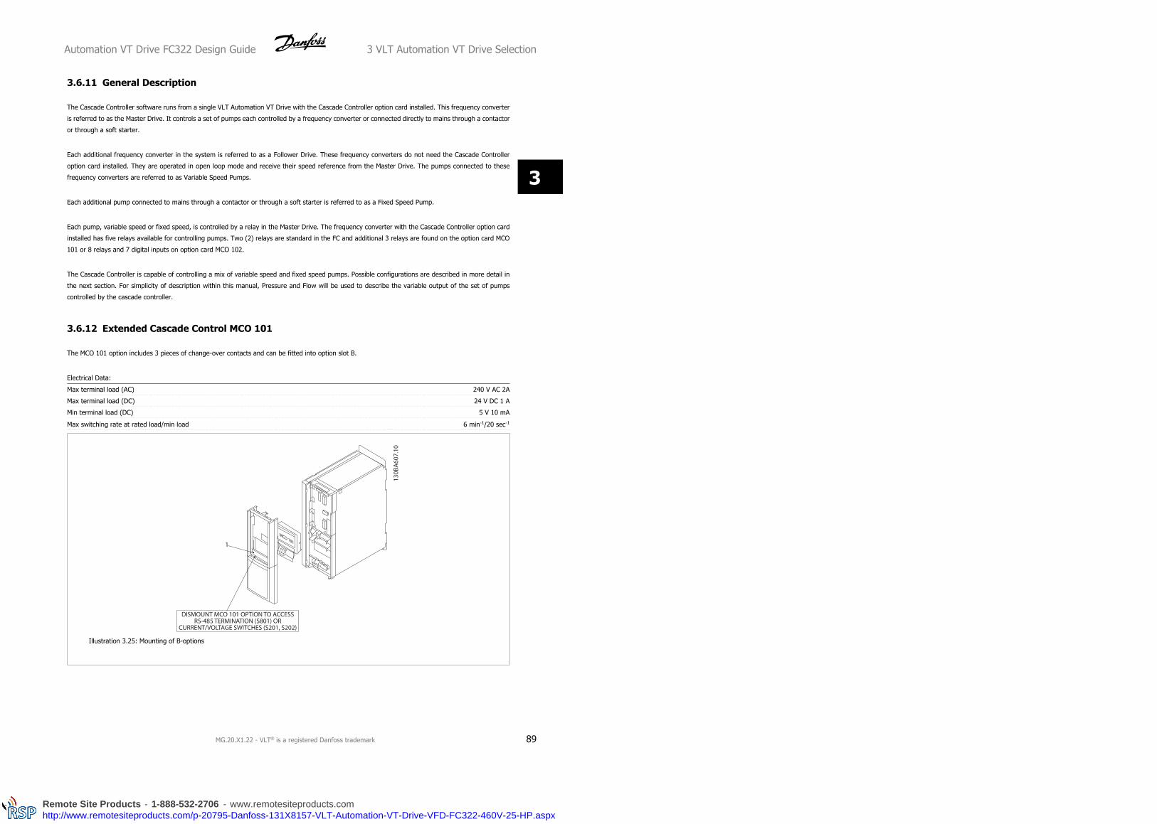
3.6.11 General Description
The Cascade Controller software runs from a single VLT Automation VT Drive with the Cascade Controller option card installed. This frequency converter
is referred to as the Master Drive. It controls a set of pumps each controlled by a frequency converter or connected directly to mains through a contactor
or through a soft starter.
Each additional frequency converter in the system is referred to as a Follower Drive. These frequency converters do not need the Cascade Controller
option card installed. They are operated in open loop mode and receive their speed reference from the Master Drive. The pumps connected to these
frequency converters are referred to as Variable Speed Pumps.
Each additional pump connected to mains through a contactor or through a soft starter is referred to as a Fixed Speed Pump.
Each pump, variable speed or fixed speed, is controlled by a relay in the Master Drive. The frequency converter with the Cascade Controller option card
installed has five relays available for controlling pumps. Two (2) relays are standard in the FC and additional 3 relays are found on the option card MCO
101 or 8 relays and 7 digital inputs on option card MCO 102.
The Cascade Controller is capable of controlling a mix of variable speed and fixed speed pumps. Possible configurations are described in more detail in
the next section. For simplicity of description within this manual, Pressure and Flow will be used to describe the variable output of the set of pumps
controlled by the cascade controller.
3.6.12 Extended Cascade Control MCO 101
The MCO 101 option includes 3 pieces of change-over contacts and can be fitted into option slot B.
Electrical Data:
Max terminal load (AC) 240 V AC 2A
Max terminal load (DC) 24 V DC 1 A
Min terminal load (DC) 5 V 10 mA
Max switching rate at rated load/min load 6 min-1/20 sec-1
Illustration 3.25: Mounting of B-options
Automation VT Drive FC322 Design Guide 3 VLT Automation VT Drive Selection
MG.20.X1.22 - VLT® is a registered Danfoss trademark 89
3
Remote Site Products - 1-888-532-2706 - www.remotesiteproducts.comhttp://www.remotesiteproducts.com/p-20795-Danfoss-131X8157-VLT-Automation-VT-Drive-VFD-FC322-460V-25-HP.aspx
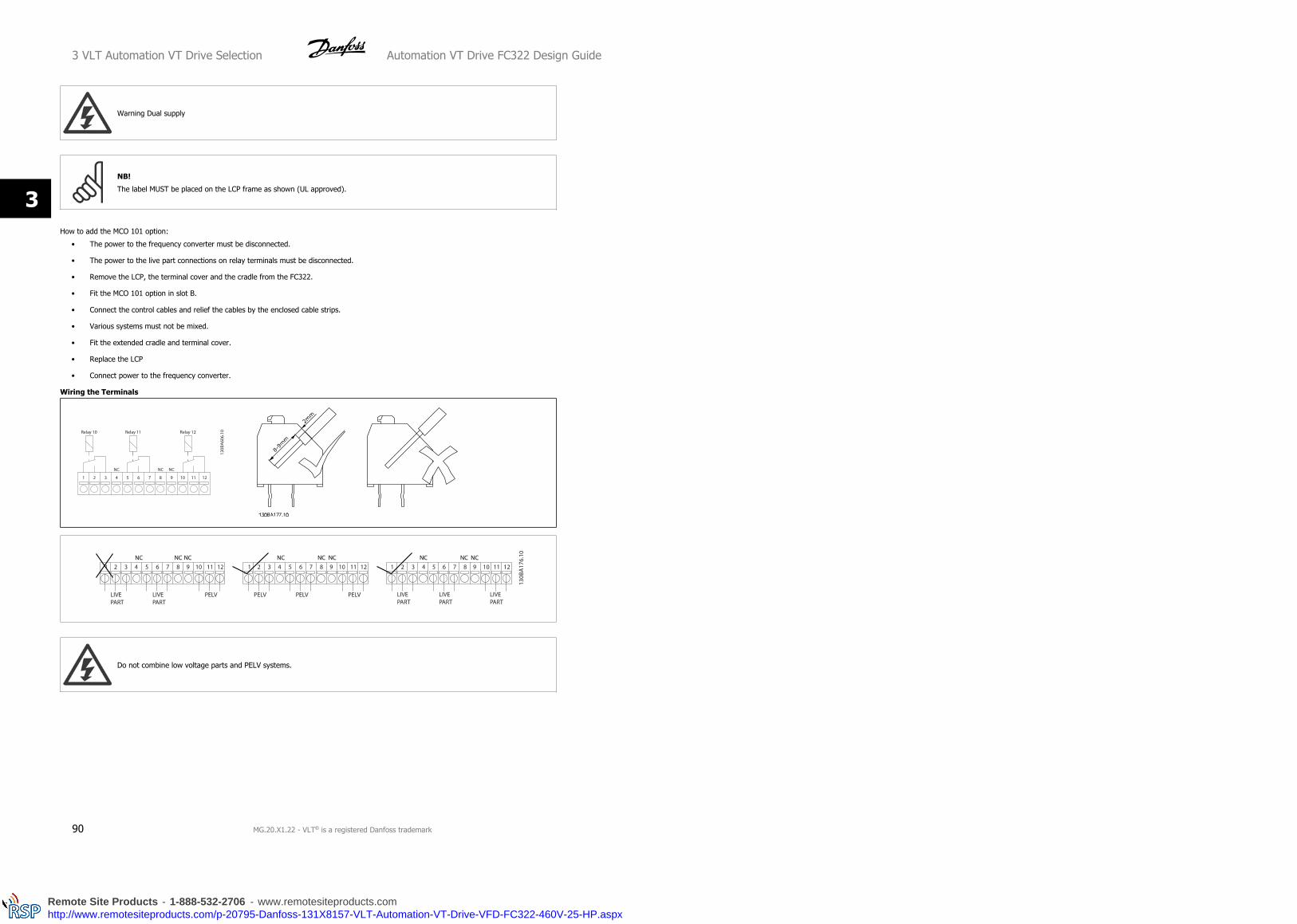
Warning Dual supply
NB!
The label MUST be placed on the LCP frame as shown (UL approved).
How to add the MCO 101 option:
• The power to the frequency converter must be disconnected.
• The power to the live part connections on relay terminals must be disconnected.
• Remove the LCP, the terminal cover and the cradle from the FC322.
• Fit the MCO 101 option in slot B.
• Connect the control cables and relief the cables by the enclosed cable strips.
• Various systems must not be mixed.
• Fit the extended cradle and terminal cover.
• Replace the LCP
• Connect power to the frequency converter.
Wiring the Terminals
Do not combine low voltage parts and PELV systems.
3 VLT Automation VT Drive Selection Automation VT Drive FC322 Design Guide
90 MG.20.X1.22 - VLT® is a registered Danfoss trademark
3
Remote Site Products - 1-888-532-2706 - www.remotesiteproducts.comhttp://www.remotesiteproducts.com/p-20795-Danfoss-131X8157-VLT-Automation-VT-Drive-VFD-FC322-460V-25-HP.aspx

3.6.13 Brake Resistors
In applications where the motor is used as a brake, energy is generated in the motor and send back into the frequency converter. If the energy can not
be transported back to the motor it will increase the voltage in the converter DC-line. In applications with frequent braking and/or high inertia loads this
increase may lead to an over voltage trip in the converter and finally a shut down. Brake resistors are used to dissipate the excess energy resulting from
the regenerative braking. The resistor is selected in respect to its ohmic value, its power dissipation rate and its physical size. Danfoss offers a wide variety
of different resistors that are specially designed to our frequency converters. See the section Control with brake function for the dimensioning of brake
resistors. Code numbers can be found in the section How to order.
Automation VT Drive FC322 Design Guide 3 VLT Automation VT Drive Selection
MG.20.X1.22 - VLT® is a registered Danfoss trademark 91
3
Remote Site Products - 1-888-532-2706 - www.remotesiteproducts.comhttp://www.remotesiteproducts.com/p-20795-Danfoss-131X8157-VLT-Automation-VT-Drive-VFD-FC322-460V-25-HP.aspx

3.6.14 Remote Mounting Kit for LCP
The Local Control Panel can be moved to the front of a cabinet by using
the remote build in kit. The enclosure is the IP65. The fastening screws
must be tightened with a torque of max. 1 Nm.
Technical data
Enclosure: IP 65 front
Max. cable length between and unit: 3 m
Communication std: RS 485
Ordering no. 130B1113 Ordering no. 130B1114
Illustration 3.26: LCP Kit with graphical LCP, fasteners, 3 m cable and
gasket.
Illustration 3.27: LCP Kit with numerical LCP, fasternes and gasket.
LCP Kit without LCP is also available. Ordering number: 130B1117
For IP55 units the ordering number is 130B1129.
3 VLT Automation VT Drive Selection Automation VT Drive FC322 Design Guide
92 MG.20.X1.22 - VLT® is a registered Danfoss trademark
3
Remote Site Products - 1-888-532-2706 - www.remotesiteproducts.comhttp://www.remotesiteproducts.com/p-20795-Danfoss-131X8157-VLT-Automation-VT-Drive-VFD-FC322-460V-25-HP.aspx

3.6.15 IP 21/IP 4X/ TYPE 1 Enclosure Kit
IP 20/IP 4X top/ TYPE 1 is an optional enclosure element available for IP 20 Compact units, enclosure size A2-A3 up to 7.5 kW.
If the enclosure kit is used, an IP 20 unit is upgraded to comply with enclosure IP 21/ 4X top/TYPE 1.
The IP 4X top can be applied to all standard IP 20 VLT Automation VT Drive variants.
A – Top cover
B – Brim
C – Base part
D – Base cover
E – Screw(s)
Place the top cover as
shown. If an A or B option
is used the brim must be fit-
ted to cover the top inlet.
Place the base part C at the
bottom of the drive and use
the clamps from the acces-
sory bag to correctly fasten
the cables. Holes for cable
glands:
Size A2: 2x M25 and 3xM32
Size A3: 3xM25 and 3xM32
A2 Enclosure A3 Enclosure
A2, A3, B3 B4, C3, C4
Automation VT Drive FC322 Design Guide 3 VLT Automation VT Drive Selection
MG.20.X1.22 - VLT® is a registered Danfoss trademark 93
3
Remote Site Products - 1-888-532-2706 - www.remotesiteproducts.comhttp://www.remotesiteproducts.com/p-20795-Danfoss-131X8157-VLT-Automation-VT-Drive-VFD-FC322-460V-25-HP.aspx

3.6.16 Input Filters
Harmonic current distortion is caused by the 6-pulse diode rectifier of the variable speed drive. The harmonic currents are affecting the installed serial
equipment identical to reactive currents. Consequently harmonic current distortion can result in overheating of the supply transformer, cables etc. De-
pending on the impedance of the power grid, harmonic current distortion can lead to voltage distortion also affecting other equipment powered by the
same transformer. Voltage distortion is increasing losses, causes premature aging and worst of all erratic operation. The majority of harmonics are reduced
by the built-in DC coil but if additional reduction is needed, Danfoss offers two types of passive filters.
The Danfoss AHF 005 and AHF 010 are advanced harmonic filters, not to be compared with traditional harmonic trap filters. The Danfoss harmonic filters
have been specially designed to match the Danfoss frequency converters.
AHF 010 is reducing the harmonic currents to less than 10% and the AHF 005 is reducing harmonic currents to less than 5% at 2% background distortion
and 2% imbalance.
3.6.17 Output Filters
The high speed switching of the frequency converter produces some secondary effects, which influence the motor and the enclosed environment. These
side effects are addressed by two different filter types, -the du/dt and the Sine-wave filter.
du/dt filters
Motor insulation stresses are often caused by the combination of rapid voltage and current increase. The rapid energy changes can also be reflected back
to the DC-line in the inverter and cause shut down. The du/dt filter is designed to reduce the voltage rise time/the rapid energy change in the motor and
by that intervention avoid premature aging and flashover in the motor insulation. du/dt filters have a positive influence on the radiation of magnetic noise
in the cable that connects the drive to the motor. The voltage wave form is still pulse shaped but the du/dt ratio is reduced in comparison with the
installation without filter.
Sine-wave filters
Sine-wave filters are designed to let only low frequencies pass. High frequencies are consequently shunted away which results in a sinusoidal phase to
phase voltage waveform and sinusoidal current waveforms.
With the sinusoidal waveforms the use of special frequency converter motors with reinforced insulation is no longer needed. The acoustic noise from the
motor is also damped as a consequence of the wave condition.
Besides the features of the du/dt filter, the sine-wave filter also reduces insulation stress and bearing currents in the motor thus leading to prolonged
motor lifetime and longer periods between services. Sine-wave filters enable use of longer motor cables in applications where the motor is installed far
from the drive. The length is unfortunately limited because the filter does not reduce leakage currents in the cables.
3 VLT Automation VT Drive Selection Automation VT Drive FC322 Design Guide
94 MG.20.X1.22 - VLT® is a registered Danfoss trademark
3
Remote Site Products - 1-888-532-2706 - www.remotesiteproducts.comhttp://www.remotesiteproducts.com/p-20795-Danfoss-131X8157-VLT-Automation-VT-Drive-VFD-FC322-460V-25-HP.aspx

3.7 High Power Options
3.7.1 Installation of Duct Cooling Kit in Rittal Enclosures
This section deals with the installation of IP00 / chassis enclosed frequency converters with duct work cooling kits in Rittal enclosures. In addition to the
enclosure a 200 mm base/plinth is required.
Illustration 3.28: Installation of IP00 in Rittal TS8 enclosure.
The minimum enclosure dimension is:
• D3 and D4 frame: Depth 500 mm and width 600 mm.
• E2 frame: Depth 600 mm and width 800 mm.
Automation VT Drive FC322 Design Guide 3 VLT Automation VT Drive Selection
MG.20.X1.22 - VLT® is a registered Danfoss trademark 95
3
Remote Site Products - 1-888-532-2706 - www.remotesiteproducts.comhttp://www.remotesiteproducts.com/p-20795-Danfoss-131X8157-VLT-Automation-VT-Drive-VFD-FC322-460V-25-HP.aspx

The maximum depth and width are as required by the installation. When using multiple frequency converters in one enclosure it is recommended that
each drive is mounted on its own back panel and supported along the mid-section of the panel. These duct work kits do not support the “in frame”
mounting of the panel (see Rittal TS8 catalogue for details). The duct work cooling kits listed in the table below are suitable for use only with IP 00 /
Chassis frequency converters in Rittal TS8 IP 20 and UL and NEMA 1 and IP 54 and UL and NEMA 12 enclosures.
For the E2 frames it is important to mount the plate at the absolute rear of the Rittal enclosure due to the weight of the frequency
converter.
NB!
A door-fan(s) is required on the Rittal cabinet to remove the loses not contained in the back-channel of the drive. The minimum door-
fan(s) airflow required at the drive maximum ambient for the D3 and D4 is 391 m^3/h (230 cfm). The minimum door-fan(s) airflow
required at the drive maximum ambient for the E2 is 782 m^3/h (460 cfm). If the ambient is below maximum or if additional compo-
nents, heat loses, are added within the enclosure a calculation must be made to ensure the proper airflow is provided to cool the inside
of the Rittal enclosure.
Ordering Information
Rittal TS-8 Enclosure Frame D3 Kit Part No. Frame D4Kit Part No. Frame E2 Part No.
1800 mm 176F1824 176F1823 Not possible
2000 mm 176F1826 176F1825 176F1850
2200 mm 176F0299
Kit Contents
• Ductwork components
• Mounting hardware
• Gasket material
• Delivered with D3 and D4 frame kits:
• 175R5639 - Mounting templates and top/bottom cut out for Rittal enclosure.
• Delivered with E2 frame kits:
• 175R1036 - Mounting templates and top/bottom cut out for Rittal enclosure.
All fasteners are either:
• 10 mm, M5 Nuts torque to 2.3 Nm (20 in-lbs)
• T25 Torx screws torque to 2.3 Nm (20 in-lbs)
NB!
Please see the Duct Kit Instruction Manual, 175R5640, for further information
External ducts
If additional duct work is added externally to the Rittal cabinet the pressure drop in the ducting must be calculated. Use the charts below to derate the
frequency converter according to the pressure drop.
3 VLT Automation VT Drive Selection Automation VT Drive FC322 Design Guide
96 MG.20.X1.22 - VLT® is a registered Danfoss trademark
3
Remote Site Products - 1-888-532-2706 - www.remotesiteproducts.comhttp://www.remotesiteproducts.com/p-20795-Danfoss-131X8157-VLT-Automation-VT-Drive-VFD-FC322-460V-25-HP.aspx

Illustration 3.29: D Frame Derating vs. Pressure Change
Drive air flow: 450 cfm (765 m3/h)
Illustration 3.30: E Frame Derating vs. Pressure Change (Small Fan), P250T5 and P355T7-P400T7
Drive air flow: 650 cfm (1105 m3/h)
Illustration 3.31: E Frame Derating vs. Pressure Change (Large Fan), P315T5-P400T5 and P500T7-P560T7
Drive air flow: 850 cfm (1445 m3/h)
Automation VT Drive FC322 Design Guide 3 VLT Automation VT Drive Selection
MG.20.X1.22 - VLT® is a registered Danfoss trademark 97
3
Remote Site Products - 1-888-532-2706 - www.remotesiteproducts.comhttp://www.remotesiteproducts.com/p-20795-Danfoss-131X8157-VLT-Automation-VT-Drive-VFD-FC322-460V-25-HP.aspx

3.7.2 Outside Installation/ NEMA 3R Kit for Rittal Enclosures
This section is for the installation of NEMA 3R kits available for the frequency converter frames D3, D4 and E2. These kits are designed and tested to be
used with IP00/ Chassis versions of these frames in Rittal TS8 NEMA 3R or NEMA 4 enclosures. The NEMA-3R enclosure is an outdoor enclosure that
provides a degree of protection against rain and ice. The NEMA-4 enclosure is an outdoor enclosure that provides a greater degree of protection against
weather and hosed water.
The minimum enclosure depth is 500 mm (600 mm for E2 frame) and the kit is designed for a 600 mm (800 mm for E2 frame) wide enclosure. Other
enclosure widths are possible, however additional Rittal hardware is required. The maximum depth and width are as required by the installation.
NB!
The current rating of drives in D3 and D4 frames are de-rated by 3%, when adding the NEMA 3R kit. Drives in E2 frames require no
derating
NB!
A door-fan(s) is required on the Rittal cabinet to remove the loses not contained in the back-channel of the drive. The minimum door-
fan(s) airflow required at the drive maximum ambient for the D3 and D4 is 391 m^3/h (230 cfm). The minimum door-fan(s) airflow
required at the drive maximum ambient for the E2 is 782 m^3/h (460 cfm). If the ambient is below maximum or if additional compo-
nents, heat loses, are added within the enclosure a calculation must be made to ensure the proper airflow is provided to cool the inside
of the Rittal enclosure.
3 VLT Automation VT Drive Selection Automation VT Drive FC322 Design Guide
98 MG.20.X1.22 - VLT® is a registered Danfoss trademark
3
Remote Site Products - 1-888-532-2706 - www.remotesiteproducts.comhttp://www.remotesiteproducts.com/p-20795-Danfoss-131X8157-VLT-Automation-VT-Drive-VFD-FC322-460V-25-HP.aspx

Ordering information
Frame size D3: 176F4600
Frame size D4: 176F4601
Frame size E2: 176F1852
Kit contents:
• Ductwork components
• Mounting hardware
• 16 mm, M5 torx screws for top vent cover
• 10 mm, M5 for attaching drive mounting plate to enclosure
• M10 nuts to attach drive to mounting plate
• Gasket material
NB!
Please see the instructions 175R5922 for further information
3.7.3 Installation on Pedestal
This section describes the installation of a pedestal unit available for the
frequency converters frames D1 and D2. This is a 200 mm high pedestal
that allows these frames to be floor mounted. The front of the pedestal
has openings for input air to the power components.
The frequency converter gland plate must be installed to provide ade-
quate cooling air to the control components of the frequency converter
via the door fan and to maintain the IP21/NEMA 1 or IP54/NEMA 12 de-
grees of enclosure protections.
Automation VT Drive FC322 Design Guide 3 VLT Automation VT Drive Selection
MG.20.X1.22 - VLT® is a registered Danfoss trademark 99
3
Remote Site Products - 1-888-532-2706 - www.remotesiteproducts.comhttp://www.remotesiteproducts.com/p-20795-Danfoss-131X8157-VLT-Automation-VT-Drive-VFD-FC322-460V-25-HP.aspx
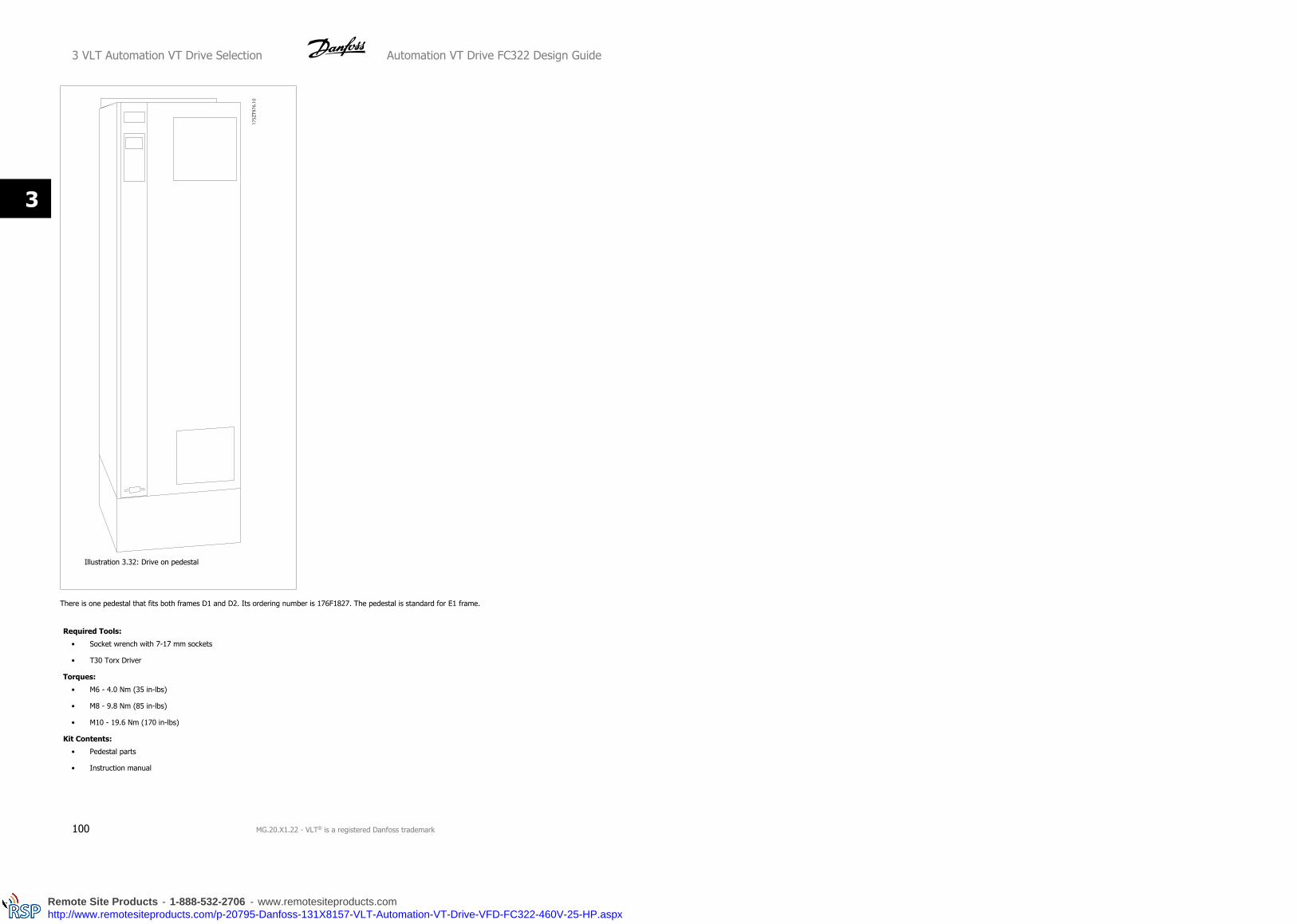
Illustration 3.32: Drive on pedestal
There is one pedestal that fits both frames D1 and D2. Its ordering number is 176F1827. The pedestal is standard for E1 frame.
Required Tools:
• Socket wrench with 7-17 mm sockets
• T30 Torx Driver
Torques:
• M6 - 4.0 Nm (35 in-lbs)
• M8 - 9.8 Nm (85 in-lbs)
• M10 - 19.6 Nm (170 in-lbs)
Kit Contents:
• Pedestal parts
• Instruction manual
3 VLT Automation VT Drive Selection Automation VT Drive FC322 Design Guide
100 MG.20.X1.22 - VLT® is a registered Danfoss trademark
3
Remote Site Products - 1-888-532-2706 - www.remotesiteproducts.comhttp://www.remotesiteproducts.com/p-20795-Danfoss-131X8157-VLT-Automation-VT-Drive-VFD-FC322-460V-25-HP.aspx
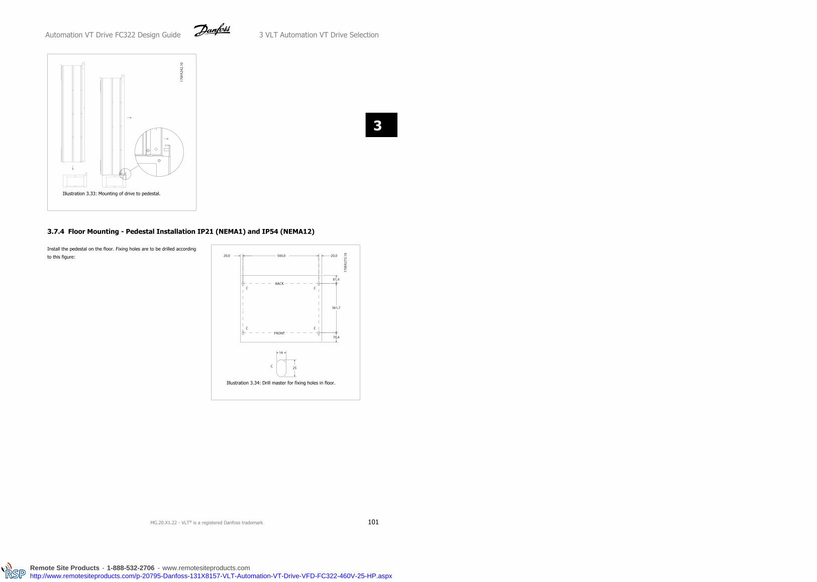
Illustration 3.33: Mounting of drive to pedestal.
3.7.4 Floor Mounting - Pedestal Installation IP21 (NEMA1) and IP54 (NEMA12)
Install the pedestal on the floor. Fixing holes are to be drilled according
to this figure:
Illustration 3.34: Drill master for fixing holes in floor.
Automation VT Drive FC322 Design Guide 3 VLT Automation VT Drive Selection
MG.20.X1.22 - VLT® is a registered Danfoss trademark 101
3
Remote Site Products - 1-888-532-2706 - www.remotesiteproducts.comhttp://www.remotesiteproducts.com/p-20795-Danfoss-131X8157-VLT-Automation-VT-Drive-VFD-FC322-460V-25-HP.aspx

Mount the drive on the pedestal and fix it with the included bolts to the
pedestal as shown on the illustration.
Illustration 3.35: Mounting of drive to pedestal
NB!
Please see the Pedestal Kit Instruction Manual, 175R5642, for further information.
3.7.5 Input Plate Option
This section is for the field installation of input option kits available for frequency converters in all D and E frames.
Do not attempt to remove RFI filters from input plates. Damage may occur to RFI filters if they are removed from the input plate.
NB!
Where RFI filters are available, there are two different type of RFI filters depending on the input plate combination and the RFI filters
interchangeable. Field installable kits in certain cases are the same for all voltages.
380 - 480 V Fuses Disconnect Fuses RFI RFI Fuses RFI Disconnect
Fuses
D1 All D1 power sizes 176F8442 176F8450 176F8444 176F8448 176F8446
D2 All D2 power sizes 176F8443 176F8441 176F8445 176F8449 176F8447
E1 315 kW 176F0253 176F0255 176F0257 176F0258 176F0260
355 - 450 kW 176F0254 176F0256 176F0257 176F0259 176F0262
3 VLT Automation VT Drive Selection Automation VT Drive FC322 Design Guide
102 MG.20.X1.22 - VLT® is a registered Danfoss trademark
3
Remote Site Products - 1-888-532-2706 - www.remotesiteproducts.comhttp://www.remotesiteproducts.com/p-20795-Danfoss-131X8157-VLT-Automation-VT-Drive-VFD-FC322-460V-25-HP.aspx

525 - 690 V Fuses Disconnect Fuses RFI RFI Fuses RFI Disconnect
Fuses
D1 45-90 kW 175L8829 175L8828 175L8777 NA NA
110-160 kW 175L8442 175L8445 175L8777 NA NA
D2 All D2 power sizes 175L8827 175L8826 175L8825 NA NA
E1 450-500 kW 176F0253 176F0255 NA NA NA
560-630 kW 176F0254 176F0258 NA NA NA
Kit contents
- Input plate assembled
- Instruction sheet 175R5795
- Modification Label
- Disconnect handle template (units w/ mains disconnect)
Cautions
- Frequency converter contains dangerous voltages when connected to line voltage. No disassembly should be attempted with
power applied
- Electrical parts of the frequency converter may contain dangerous voltages even after the mains have been disconnected.
Wait the minimum time listed on the drive label after disconnecting the mains before touching any internal components to
ensure that capacitors have fully discharged
- The input plates contain metal parts with sharp edges. Use hand protection when removing and reinstalling.
- E frames input plates are heavy (20-35 kg depending on configuration). It is recommended that the disconnect switch be
removed from input plate for easier installation and be reinstalled on the input plate after the input plate has been installed
on the drive
NB!
For further information, please see the Instruction Sheet, 175R5795
3.7.6 Installation of Mains Shield for Frequency Converters
This section is for the installation of a mains shield for the frequency converter series with D1, D2 and E1 frames. It is not possible to install in the IP00/
Chassis versions as these have included as standard a metal cover. These shields satisfy VBG-4 requirements.
Ordering numbers:
Frames D1 and D2 : 176F0799
Frame E1: 176F1851
Torque requirements
M6 - 35 in-lbs (4.0 N-M)
M8 - 85 in-lbs (9.8 N-M)
M10 - 170 in-lbs (19.6 N-M)
Automation VT Drive FC322 Design Guide 3 VLT Automation VT Drive Selection
MG.20.X1.22 - VLT® is a registered Danfoss trademark 103
3
Remote Site Products - 1-888-532-2706 - www.remotesiteproducts.comhttp://www.remotesiteproducts.com/p-20795-Danfoss-131X8157-VLT-Automation-VT-Drive-VFD-FC322-460V-25-HP.aspx

NB!
For further information, please see the Instruction Sheet, 175R5923
3.7.7 Frame size F Panel Options
Space Heaters and Thermostat
Mounted on the cabinet interior of frame size F frequency converters, space heaters controlled via automatic thermostat help control humidity inside the
enclosure, extending the lifetime of drive components in damp environments.
Cabinet Light with Power Outlet
A light mounted on the cabinet interior of frame size F frequency converters increase visibility during servicing and maintenance. The housing the light
includes a power outlet for temporarily powering tools or other devices, available in two voltages:
• 230V, 50Hz, 2.5A, CE/ENEC
• 120V, 60Hz, 5A, UL/cUL
Transformer Tap Setup
If the Cabinet Light & Outlet and/or the Space Heaters & Thermostat are installed Transformer T1 requires it taps to be set to the proper input voltage.
A 380-480/ 500 V380-480 V drive will initially be set to the 525 V tap and a 525-690 V drive will be set to the 690 V tap to insure no over-voltage of
secondary equipment occurs if the tap is not changed prior to power being applied. See the table below to set the proper tap at terminal T1 located in
the rectifier cabinet. For location in the drive, see illustration of rectifier in the Power Connections section.
Input Voltage Range Tap to Select
380V-440V 400V
441V-490V 460V
491V-550V 525V
551V-625V 575V
626V-660V 660V
661V-690V 690V
NAMUR Terminals
NAMUR is an international association of automation technology users in the process industries, primarily chemical and pharmaceutical industries in
Germany. Selection of this option provides terminals organized and labeled to the specifications of the NAMUR standard for drive input and output
terminals. This requires MCB 112 PTC Thermistor Card and MCB 113 Extended Relay Card.
RCD (Residual Current Device)
Uses the core balance method to monitor ground fault currents in grounded and high-resistance grounded systems (TN and TT systems in IEC termi-
nology). There is a pre-warning (50% of main alarm set-point) and a main alarm set-point. Associated with each set-point is an SPDT alarm relay for
external use. Requires an external “window-type” current transformer (supplied and installed by customer).
• Integrated into the drive’s safe-stop circuit
• IEC 60755 Type B device monitors AC, pulsed DC, and pure DC ground fault currents
• LED bar graph indicator of the ground fault current level from 10–100% of the set-point
• Fault memory
• TEST / RESET button
Insulation Resistance Monitor (IRM)
Monitors the insulation resistance in ungrounded systems (IT systems in IEC terminology) between the system phase conductors and ground. There is
an ohmic pre-warning and a main alarm set-point for the insulation level. Associated with each set-point is an SPDT alarm relay for external use. Note:
only one insulation resistance monitor can be connected to each ungrounded (IT) system.
• Integrated into the drive’s safe-stop circuit
• LCD display of the ohmic value of the insulation resistance
3 VLT Automation VT Drive Selection Automation VT Drive FC322 Design Guide
104 MG.20.X1.22 - VLT® is a registered Danfoss trademark
3
Remote Site Products - 1-888-532-2706 - www.remotesiteproducts.comhttp://www.remotesiteproducts.com/p-20795-Danfoss-131X8157-VLT-Automation-VT-Drive-VFD-FC322-460V-25-HP.aspx

• Fault Memory
• INFO, TEST, and RESET buttons
IEC Emergency Stop with Pilz Safety Relay
Includes a redundant 4-wire emergency-stop push-button mounted on the front of the enclosure and a Pilz relay that monitors it in conjunction with the
drive’s safe-stop circuit and the mains contactor located in the options cabinet.
Manual Motor Starters
Provide 3-phase power for electric blowers often required for larger motors. Power for the starters is provided from the load side of any supplied contactor,
circuit breaker, or disconnect switch. Power is fused before each motor starter, and is off when the incoming power to the drive is off. Up to two starters
are allowed (one if a 30A, fuse-protected circuit is ordered). Integrated into the drive’s safe-stop circuit.
Unit features include:
• Operation switch (on/off)
• Short-circuit and overload protection with test function
• Manual reset function
30 Ampere, Fuse-Protected Terminals
• 3-phase power matching incoming mains voltage for powering auxiliary customer equipment
• Not available if two manual motor starters are selected
• Terminals are off when the incoming power to the drive is off
• Power for the fused protected terminals will be provided from the load side of any supplied contactor, circuit breaker, or disconnect switch.
24 VDC Power Supply
• 5 amp, 120 W, 24 VDC
• Protected against output over-current, overload, short circuits, and over-temperature
• For powering customer-supplied accessory devices such as sensors, PLC I/O, contactors, temperature probes, indicator lights, and/or other
electronic hardware
• Diagnostics include a dry DC-ok contact, a green DC-ok LED, and a red overload LED
External Temperature Monitoring
Designed for monitoring temperatures of external system components, such as the motor windings and/or bearings. Includes eight universal input modules
plus two dedicated thermistor input modules. All ten modules are integrated into the drive’s safe-stop circuit and can be monitored via a fieldbus network
(requires the purchase of a separate module/bus coupler).
Universal inputs (8)
Signal types:
• RTD inputs (including Pt100), 3-wire or 4-wire
• Thermocouple
• Analog current or analog voltage
Additional features:
• One universal output, configurable for analog voltage or analog current
• Two output relays (N.O.)
• Dual-line LC display and LED diagnostics
• Sensor lead wire break, short-circuit, and incorrect polarity detection
• Interface setup software
Dedicated thermistor inputs (2)
Features:
• Each module capable of monitoring up to six thermistors in series
• Fault diagnostics for wire breakage or short-circuits of sensor leads
• ATEX/UL/CSA certification
• A third thermistor input can be provided by the PTC Thermistor Option Card MCB 112, if necessary
Automation VT Drive FC322 Design Guide 3 VLT Automation VT Drive Selection
MG.20.X1.22 - VLT® is a registered Danfoss trademark 105
3
Remote Site Products - 1-888-532-2706 - www.remotesiteproducts.comhttp://www.remotesiteproducts.com/p-20795-Danfoss-131X8157-VLT-Automation-VT-Drive-VFD-FC322-460V-25-HP.aspx

4 How to Order Automation VT Drive FC322 Design Guide
106 MG.20.X1.22 - VLT® is a registered Danfoss trademark
4
Remote Site Products - 1-888-532-2706 - www.remotesiteproducts.comhttp://www.remotesiteproducts.com/p-20795-Danfoss-131X8157-VLT-Automation-VT-Drive-VFD-FC322-460V-25-HP.aspx

4 How to Order
4.1 Ordering Form
4.1.1 Drive Configurator
It is possible to design a VLT Automation VT Drive frequency converter according to the application requirements by using the ordering number system.
For the VLT Automation VT Drive, you can order standard drives and drives with integral options by sending a type code string describing the product a
to the Danfoss sales office, i.e.:
FC-322P18KT4E21H1XGCXXXSXXXXAGBKCXXXXDX
The meaning of the characters in the string can be located in the pages containing the ordering numbers in the chapter How to Select Your VLT. In the
example above, a Profibus LON works option and a General purpose I/O option is included in the drive.
Ordering numbers for VLT Automation VT Drive standard variants can also be located in the chapter How to Select Your VLT.
From the Internet based Drive Configurator, you can configure the right drive for the right application and generate the type code string. The Drive
Configurator will automatically generate an eight-digit sales number to be delivered to your local sales office.
Furthermore, you can establish a project list with several products and send it to a Danfoss sales representative.
The Drive Configurator can be found on the global Internet site: www.danfoss.com/drives.
Automation VT Drive FC322 Design Guide 4 How to Order
MG.20.X1.22 - VLT® is a registered Danfoss trademark 107
4
Remote Site Products - 1-888-532-2706 - www.remotesiteproducts.comhttp://www.remotesiteproducts.com/p-20795-Danfoss-131X8157-VLT-Automation-VT-Drive-VFD-FC322-460V-25-HP.aspx

4.1.2 Type Code String
Description Pos.: Possible choice
Product group & VLT Series 1-6 FC322
Power rating 7-10 0.25 - 1200 kW
Number of phases 11 Three phases (T)
Mains voltage 11-12
S2: 220-240 VAC single phase
S4: 380-480 VAC single phase
T 2: 200-240 VAC
T 4: 380-480 VAC
T 6: 525-600 VAC
T 7: 525-690 VAC
Enclosure 13-15
E20: IP20
E21: IP 21/NEMA Type 1
E55: IP 55/NEMA Type 12
E2M: IP21/NEMA Type 1 w/mains shield
E5M: IP 55/NEMA Type 12 w/mains shield
E66: IP66
F21: IP21 kit without backplate
G21: IP21 kit with backplate
P20: IP20/Chassis with backplate
P21: IP21/NEMA Type 1 w/backplate
P55: IP55/NEMA Type 12 w/backplate
RFI filter 16-17
HX: No RFI filter
H1: RFI filter class A1/B
H2: RFI filter class A2
H3: RFI filter class A1/B (reduced cable length)
H4: RFI filter class A2/A1
Brake 18
X: No brake chopper included
B: Brake chopper included
T: Safe Stop
U: Safe + brake
Display 19
G: Graphical Local Control Panel (GLCP)
N: Numeric Local Control Panel (NLCP)
X: No Local Control Panel
Coating PCB 20X. No coated PCB
C: Coated PCB
Mains option 21
D: Loadsharing
X: No Mains disconnect switch
8: Mains Disconnect + Loadsharing
Cable entries 22X: Standard cable entries
O: European metric thread in cable entries
23 Reserved
Software release 24-27 Actual software version
Software language 28
A options 29-30 AX: No options
4 How to Order Automation VT Drive FC322 Design Guide
108 MG.20.X1.22 - VLT® is a registered Danfoss trademark
4
Remote Site Products - 1-888-532-2706 - www.remotesiteproducts.comhttp://www.remotesiteproducts.com/p-20795-Danfoss-131X8157-VLT-Automation-VT-Drive-VFD-FC322-460V-25-HP.aspx

Description Pos.: Possible choice
A0: MCA 101 Profibus DP V1
A4: MCA 104 DeviceNet
AN: MCA 121 Ethernet IP
B options 31-32
BX: No option
BK: MCB 101 General purpose I/O option
BP: MCB 105 Relay option
BO:MCB 109 Analog I/O option
BY: MCO 101 Extended Cascade Control
C0 options 33-34 CX: No options
C1 options 35X: No options
5: MCO 102 Advanced Cascade Control
C option software 36-37 XX: Standard software
D options 38-39DX: No option
D0: DC backup
The various options are described further in this Design Guide.
Table 4.1: Type code description.
Automation VT Drive FC322 Design Guide 4 How to Order
MG.20.X1.22 - VLT® is a registered Danfoss trademark 109
4
Remote Site Products - 1-888-532-2706 - www.remotesiteproducts.comhttp://www.remotesiteproducts.com/p-20795-Danfoss-131X8157-VLT-Automation-VT-Drive-VFD-FC322-460V-25-HP.aspx

4.1.3 Type Code String High Power
Ordering type code frame sizes D and E
Description Pos Possible choice
Product group 1-3
Drive series 4-6
Power rating 8-10 45-560 kW
Phases 11 Three phases (T)
Mains voltage 11-
12
T 5: 380-500 V AC
T 7: 525-690 V AC
Enclosure 13-
15
E00: IP00/Chassis
C00: IP00/Chassis w/ stainless steel back channel
E0D: IP00/Chassis, D3 P37K-P75K, T7
C0D: IP00/Chassis w/ stainless steel back channel, D3 P37K-P75K, T7
E21: IP 21/ NEMA Type 1
E54: IP 54/ NEMA Type 12
E2D: IP 21/ NEMA Type 1, D1 P37K-P75K, T7
E5D: IP 54/ NEMA Type 12, D1 P37K-P75K, T7
E2M: IP 21/ NEMA Type 1 with mains shield
E5M: IP 54/ NEMA Type 12 with mains shield
RFI filter 16-
17
H2: RFI filter, class A2 (standard)
H4: RFI filter class A11)
H6: RFI filter Maritime use2)
Brake 18 B: Brake IGBT mounted
X: No brake IGBT
R: Regeneration terminals (E frames only)
Display 19 G: Graphical Local Control Panel LCP
N: Numerical Local Control Panel (LCP)
X: No Local Control Panel (D frames IP00 and IP 21 only)
Coating PCB 20 C: Coated PCB
X. No coated PCB (D frames 380-480/500 V only)
Mains option 21 X: No mains option
3: Mains disconnect and Fuse
5: Mains disconnect, Fuse and Load sharing
7: Fuse
A: Fuse and Load sharing
D: Load sharing
Adaptation 22 Reserved
Adaptation 23 Reserved
Software release 24-
27
Actual software
Software language 28
A options 29-30 AX: No options
A0: MCA 101 Profibus DP V1
A4: MCA 104 DeviceNet
AN: MCA 121 Ethernet IP
B options 31-32 BX: No option
BK: MCB 101 General purpose I/O option
BP: MCB 105 Relay option
BO:MCB 109 Analog I/O option
BY: MCO 101 Extended Cascade Control
C0 options 33-34 CX: No options
C1 options 35 X: No options
5: MCO 102 Advanced Cascade Control
C option software 36-37 XX: Standard software
D options 38-39 DX: No option
D0: DC backup
The various options are described further in this Design Guide.
1): Available for all D frames. E frames 380-480/500 V only
2) Consult factory for applications requiring maritime certification
4 How to Order Automation VT Drive FC322 Design Guide
110 MG.20.X1.22 - VLT® is a registered Danfoss trademark
4
Remote Site Products - 1-888-532-2706 - www.remotesiteproducts.comhttp://www.remotesiteproducts.com/p-20795-Danfoss-131X8157-VLT-Automation-VT-Drive-VFD-FC322-460V-25-HP.aspx

4.2 Ordering Numbers
4.2.1 Ordering Numbers: Options and Accessories
Type Description Ordering no.
Miscellaneous hardware
DC link connector Terminal block for DC link connection, frame size A2/A3 130B1064
IP 21/4X top/TYPE 1 kit Enclosure, frame size A2: IP21/IP 4X Top/TYPE 1 130B1122
IP 21/4X top/TYPE 1 kit Enclosure, frame size A3: IP21/IP 4X Top/TYPE 1 130B1123
IP21/TYPE 1 Kit Top and bottom, frame size B3 130B1187
IP21/TYPE 1 Kit Top and bottom, frame size B4 130B1189
IP21/TYPE 1 Kit Top and bottom, frame size C3 130B1191
IP21/TYPE 1 Kit Top and bottom, frame size C4 130B1193
IP21/TYPE 1 Kit Top, frame size B3 130B1188
IP21/TYPE 1 Kit Top, frame size B4 130B1190
IP21/TYPE 1 Kit Top, frame size C3 130B1192
IP21/TYPE 1 Kit Top, frame size C4 130B1194
MCF 110 panel Panel Through Mounting Kit, frame size A5 130B1028
MCF 110 panel Panel Through Mounting Kit, frame size B1 130B1046
MCF 110 panel Panel Through Mounting Kit, frame size B2 130B1047
MCF 110 panel Panel Through Mounting Kit, frame size C1 130B1048
MCF 110 panel Panel Through Mounting Kit, frame size C2 130B1049
Profibus D-Sub 9 Connector kit for IP20 130B1112
MCF 103 USB Cable 350 mm, IP55/66 130B1155
MCF 103 USB Cable 650 mm, IP55/66 130B1156
Profibus top entry kit Top entry kit for Profibus connection - only A enclosures 130B05241)
Terminal blocks Screw terminal blocks for replacing spring loaded terminals
1 pc 10 pin 1 pc 6 pin and 1 pc 3 pin connectors 130B1116
Backplate IP21 / NEMA 1 enclosure Top Cover A2 130B1132
Backplate IP21 / NEMA 1 enclosure Top Cover A3 130B1133
Backplate A5, IP55 / NEMA 12 130B1098
Backplate B1, IP21 / IP55 / NEMA 12 130B3383
Backplate B2, IP21 / IP55 / NEMA 12 130B3397
Backplate C1, IP21 / IP55 / NEMA 12 130B3910
Backplate C2, IP21 / IP55 / NEMA 12 130B3911
Backplate A5, IP66 / NEMA 4x 130B3242
Backplate B1, IP66 / NEMA 4x 130B3434
Backplate B2, IP66 / NEMA 4x 130B3465
Backplate C1, IP66 / NEMA 4x 130B3468
Backplate C2, IP66 / NEMA 4x 130B3491
LCP
LCP 101 Numerical Local Control Panel (NLCP) 130B1124
LCP 102 Graphical Local Control Panel (GLCP) 130B1107
LCP cable Separate LCP cable, 3 m 175Z0929
LCP kit Panel mounting kit including graphical LCP, fasteners, 3 m cable and gasket 130B1113
LCP kit Panel mounting kit including numerical LCP, fasteners and gasket 130B1114
LCP kit Panel mounting kit for all LCPs including fasteners, 3 m cable and gasket 130B1117
LCP kit Panel mounting kit for all LCPs including fasteners and gasket - without ca-
ble
130B1170
LCP kit Panel mounting kit for all LCPs including fasteners, 8 m cable, glands and
gasket for IP55/66 enclosures
130B1129
Options for Slot A Uncoated / Coated Uncoated Coated
MCA 101 Profibus option DP V0/V1 130B1100 130B1200
MCA 104 DeviceNet option 130B1102 130B1202
MCA 108 LON works 130B1106 130B1206
Automation VT Drive FC322 Design Guide 4 How to Order
MG.20.X1.22 - VLT® is a registered Danfoss trademark 111
4
Remote Site Products - 1-888-532-2706 - www.remotesiteproducts.comhttp://www.remotesiteproducts.com/p-20795-Danfoss-131X8157-VLT-Automation-VT-Drive-VFD-FC322-460V-25-HP.aspx

Type Description Ordering no.
Options for Slot B
MCB 101 General purpose Input Output option 130B1125 130B1212
MCB 105 Relay option 130B1110 130B1210
MCB 109 Analog I/O option 130B1143 130B1243
MCB 114 PT 100 / PT 1000 sensor input 130B1172 10B1272
MCO 101 Extended Cascade Control 130B1118 130B1218
Options for C0
Mounting kit for frame size A2 and A3 (40 mm for one C option) 130B7530
Mounting kit for frame size A2 and A3 (60 mm for C0 + C1 option) 130B7531
Mounting kit for frame size A5 130B7532
Mounting kit for frame size B, C, D. E and F2 and 3 (except B3) 130B7533
Mounting kit for frame size B3 (40 mm for one C option) 130B1413
Mounting kit for frame size B3 (60 mm for C0 + C1 option) 130B1414
Option for Slot C
MCO 102 Advanced Cascade Control 130B1154 130B1254
Option for Slot D
MCB 107 24 V DC back-up 130B1108 130B1208
Type Description Ordering no.
External Options
Ethernet IP Ethernet 130B1119 130B1219
Spare Parts
Control board VLT Automation VT Drive With Safe Stop Function 130B1167
Control board VLT Automation VT Drive Without Safe Stop Function 130B1168
Accessory bag Control Terminals 130B0295
Fan A2 Fan, frame size A2 130B1009
Fan A3 Fan, frame size A3 130B1010
Fan A5 Fan, frame size A5 130B1017
Fan B1 Fan external, frame size B1 130B1013
Fan B2 Fan external, frame size B2 130B1015
Fan B3 Fan external, frame size B3 130B3563
Fan B4 Fan external, frame size B4 130B3699
Fan B4 Fan external, frame size B5 130B3701
Fan C1 Fan external, frame size C1 130B3865
Fan C2 Fan external, frame size C2 130B3867
Fan C3 Fan external, frame size C3 130B4292
Fan C4 Fan external, frame size C4 130B4294
Accessory bag A2 Accessory bag, frame size A2 130B0509
Accessory bag A3 Accessory bag, frame size A3 130B0510
Accessory bag A5 Accessory bag, frame size A5 130B1023
Accessory bag B1 Accessory bag, frame size B1 130B2060
Accessory bag B2 Accessory bag, frame size B2 130B2061
Accessory bag B3 Accessory bag, frame size B3 130B0980
Accessory bag B4 Accessory bag, frame size B4 130B1300 Small
Accessory bag B4 Accessory bag, frame size B4 130B1301 Big
Accessory bag C1 Accessory bag, frame size C1 130B0046
Accessory bag C2 Accessory bag, frame size C2 130B0047
Accessory bag C3 Accessory bag, frame size C3 130B0981
Accessory bag C4 Accessory bag, frame size C4 130B0982 Small
Accessory bag C4 Accessory bag, frame size C4 130B0983 Big
1) Only IP21 / > 11 kW
4 How to Order Automation VT Drive FC322 Design Guide
112 MG.20.X1.22 - VLT® is a registered Danfoss trademark
4
Remote Site Products - 1-888-532-2706 - www.remotesiteproducts.comhttp://www.remotesiteproducts.com/p-20795-Danfoss-131X8157-VLT-Automation-VT-Drive-VFD-FC322-460V-25-HP.aspx

Options can be ordered as factory built-in options, see ordering information.
For information on fieldbus and application option compatibility with older software versions, please contact your Danfoss supplier.
Automation VT Drive FC322 Design Guide 4 How to Order
MG.20.X1.22 - VLT® is a registered Danfoss trademark 113
4
Remote Site Products - 1-888-532-2706 - www.remotesiteproducts.comhttp://www.remotesiteproducts.com/p-20795-Danfoss-131X8157-VLT-Automation-VT-Drive-VFD-FC322-460V-25-HP.aspx

4.2.2 Ordering Numbers: Harmonic Filters
Harmonic filters are used to reduce mains harmonics.
• AHF 010: 10% current distortion
• AHF 005: 5% current distortion
380-415V, 50Hz
IAHF,N Typical Motor Used [kW] Danfoss ordering numberFrequency converter size
AHF 005 AHF 010
10 A 1.1 - 4 175G6600 175G6622 P1K1, P4K0
19 A 5.5 - 7.5 175G6601 175G6623 P5K5 - P7K5
26 A 11 175G6602 175G6624 P11K
35 A 15 - 18.5 175G6603 175G6625 P15K - P18K
43 A 22 175G6604 175G6626 P22K
72 A 30 - 37 175G6605 175G6627 P30K - P37K
101A 45 - 55 175G6606 175G6628 P45K - P55K
144 A 75 175G6607 175G6629 P75K
180 A 90 175G6608 175G6630 P90K
217 A 110 175G6609 175G6631 P110
289 A 132 - 160 175G6610 175G6632 P132 - P160
324 A 175G6611 175G6633
370 A 200 175G6688 175G6691 P200
506 A 250175G6609
+ 175G6610
175G6631
+ 175G6632P250
578 A 315 2x 175G6610 2x 175G6632 P315
648 A 400 2x175G6611 2x175G6633 P400
380 - 415V, 60Hz
IAHF,N Typical Motor Used [HP] Danfoss ordering numberFrequency converter size
AHF 005 AHF 010
19 A 10 - 15 130B2460 130B2472 P5K5 - P7K5
26 A 20 130B2461 130B2473 P11K
35 A 25 - 30 130B2462 130B2474 P15K, P18K
43 A 40 130B2463 130B2475 P22K
72 A 50 - 60 130B2464 130B2476 P30K - P37K
101A 75 130B2465 130B2477 P45K - P55K
144 A 100 - 125 130B2466 130B2478 P75K
180 A 150 130B2467 130B2479 P90K
217 A 200 130B2468 130B2480 P110
289 A 250 130B2469 130B2481 P132
324 A 300 130B2470 130B2482 P160
370 A 350 130B2471 130B2483 P200
506 A 450 130B2468
+ 130B2469
130B2480
+ 130B2481
P250
578 A 500 2x 130B2469 2x 130B2481 P315
648 A 500 2x130B2470 2x130B2482 P355
4 How to Order Automation VT Drive FC322 Design Guide
114 MG.20.X1.22 - VLT® is a registered Danfoss trademark
4
Remote Site Products - 1-888-532-2706 - www.remotesiteproducts.comhttp://www.remotesiteproducts.com/p-20795-Danfoss-131X8157-VLT-Automation-VT-Drive-VFD-FC322-460V-25-HP.aspx

440-480V, 60Hz
IAHF,N Typical Motor Used [HP] Danfoss ordering numberFrequency converter size
AHF 005 AHF 010
19 A 10 - 15 175G6612 175G6634 P11K
26 A 20 175G6613 175G6635 P15K
35 A 25 - 30 175G6614 175G6636 P18K, P22K
43 A 40 175G6615 175G6637 P30K
72 A 50 - 60 175G6616 175G6638 P37K - P45K
101A 75 175G6617 175G6639 P55K
144 A 100 - 125 175G6618 175G6640 P75K
180 A 150 175G6619 175G6641 P90
217 A 200 175G6620 175G6642 P110
289 A 250 175G6621 175G6643 P132 - P160
324 A 300 175G6689 175G6692
370 A 350 175G6690 175G6693 P200
434 A 350 2x175G6620 2x175G6642 P250
578 A 500 2x 175G6621 2x 175G6643 P315 - P355
659 A 550-600 175G6690 + 175G6621 175G6693 + 175G6643 P400
Matching the frequency converter and filter is pre-calculated based on 400V/480V and on a typical motor load (4 pole) and 110 % torque.
500-525V, 50Hz
IAHF,N Typical Motor Used [kW] Danfoss ordering numberFrequency converter size
AHF 005 AHF 010
10 A 0.75 - 5.5 175G6644 175G6656 PK75 - P5K5
19 A 7.5 - 11 175G6645 175G6657 P7K5 - P11K
26 A 15 18.5 175G6646 175G6658 P15K - P18K
35 A 22 175G6647 175G6659 P22K
43 A 30 175G6648 175G6660 P30K
72 A 37 -45 175G6649 175G6661 P37K - P45K
101 A 55 - 75 175G6650 175G6662 P55K - P75K
144 A 90 - 110 175G6651 175G6663 P90K - P110
180 A 132 175G6652 175G6664 P132
217 A 160 175G6653 175G6665 P160
289 A 200 175G6654 175G6666 P200
324 A 250 175G6655 175G6667 P250
370 A 315 2x175G6653 2x175G6665 P315 - P400
578 A 400 2X 175G6654 2X 175G6666 P500 - P560
Automation VT Drive FC322 Design Guide 4 How to Order
MG.20.X1.22 - VLT® is a registered Danfoss trademark 115
4
Remote Site Products - 1-888-532-2706 - www.remotesiteproducts.comhttp://www.remotesiteproducts.com/p-20795-Danfoss-131X8157-VLT-Automation-VT-Drive-VFD-FC322-460V-25-HP.aspx

690V, 50Hz
IAHF,N Typical Motor Used [kW] Danfoss ordering numberFrequency converter size
AHF 005 AHF 010
43 37 - 45 130B2328 130B2293
72 55 - 75 130B2330 130B2295 P37K - P45K
101 90 130B2331 130B2296 P55K - P75K
144 A 110 - 132 130B2333 130B2298 P90K - P110
180 A 160 130B2334 130B2299 P132
217 A 200 130B2335 130B2300 P160
289 A 250 130B2331+2333 130B2301 P200
324 A 315 130B2333+2334 130B2302 P250
370 A 400 130B2334+2335 130B2304 P315
4 How to Order Automation VT Drive FC322 Design Guide
116 MG.20.X1.22 - VLT® is a registered Danfoss trademark
4
Remote Site Products - 1-888-532-2706 - www.remotesiteproducts.comhttp://www.remotesiteproducts.com/p-20795-Danfoss-131X8157-VLT-Automation-VT-Drive-VFD-FC322-460V-25-HP.aspx

4.2.3 Ordering Numbers: Sine Wave Filter Modules, 200-500 VAC
Mains supply 3 x 200 to 500 V
Frequency converter size Minimum switching
frequency
Maximum output
frequencyPart No. IP20 Part No. IP00
Rated filter current at
50Hz200-240V 380-440V 440-500V
PK25 PK37 PK37 5 kHz 120 Hz 130B2439 130B2404 2.5 A
PK37 PK55 PK55 5 kHz 120 Hz 130B2439 130B2404 2.5 A
PK75 PK75 5 kHz 120 Hz 130B2439 130B2404 2.5 A
PK55 P1K1 P1K1 5 kHz 120 Hz 130B2441 130B2406 4.5 A
P1K5 P1K5 5 kHz 120 Hz 130B2441 130B2406 4.5 A
PK75 P2K2 P2K2 5 kHz 120 Hz 130B2443 130B2408 8 A
P1K1 P3K0 P3K0 5 kHz 120 Hz 130B2443 130B2408 8 A
P1K5 5 kHz 120 Hz 130B2443 130B2408 8 A
P4K0 P4K0 5 kHz 120 Hz 130B2444 130B2409 10 A
P2K2 P5K5 P5K5 5 kHz 120 Hz 130B2446 130B2411 17 A
P3K0 P7K5 P7K5 5 kHz 120 Hz 130B2446 130B2411 17 A
P4K0 5 kHz 120 Hz 130B2446 130B2411 17 A
P5K5 P11K P11K 4 kHz 60 Hz 130B2447 130B2412 24 A
P7K5 P15K P15K 4 kHz 60 Hz 130B2448 130B2413 38 A
P18K P18K 4 kHz 60 Hz 130B2448 130B2413 38 A
P11K P22K P22K 4 kHz 60 Hz 130B2307 130B2281 48 A
P15K P30K P30K 3 kHz 60 Hz 130B2308 130B2282 62 A
P18K P37K P37K 3 kHz 60 Hz 130B2309 130B2283 75 A
P22K P45K P55K 3 kHz 60 Hz 130B2310 130B2284 115 A
P30K P55K P75K 3 kHz 60 Hz 130B2310 130B2284 115 A
P37K P75K P90K 3 kHz 60 Hz 130B2311 130B2285 180 A
P45K P90K P110 3 kHz 60 Hz 130B2311 130B2285 180 A
P110 P132 3 kHz 60 Hz 130B2312 130B2286 260 A
P132 P160 3 kHz 60 Hz 130B2312 130B2286 260 A
P160 P200 3 kHz 60 Hz 130B2313 130B2287 410 A
P200 P250 3 kHz 60 Hz 130B2313 130B2287 410 A
P250 P315 3 kHz 60 Hz 130B2314 130B2288 480 A
P315 P355 2 kHz 60 Hz 130B2315 130B2289 660 A
P355 P400 2 kHz 60 Hz 130B2315 130B2289 660 A
P400 P450 2 kHz 60 Hz 130B2316 130B2290 750 A
P450 P500 2 kHz 60 Hz 130B2317 130B2291 880 A
P500 P560 2 kHz 60 Hz 130B2317 130B2291 880 A
P560 P630 2 kHz 60 Hz 130B2318 130B2292 1200 A
P630 P710 2 kHz 60 Hz 130B2318 130B2292 1200 A
NB!
When using Sine-wave filters, the switching frequency should comply with filter specifications in par. 14-01 Switching Frequency.
Automation VT Drive FC322 Design Guide 4 How to Order
MG.20.X1.22 - VLT® is a registered Danfoss trademark 117
4
Remote Site Products - 1-888-532-2706 - www.remotesiteproducts.comhttp://www.remotesiteproducts.com/p-20795-Danfoss-131X8157-VLT-Automation-VT-Drive-VFD-FC322-460V-25-HP.aspx
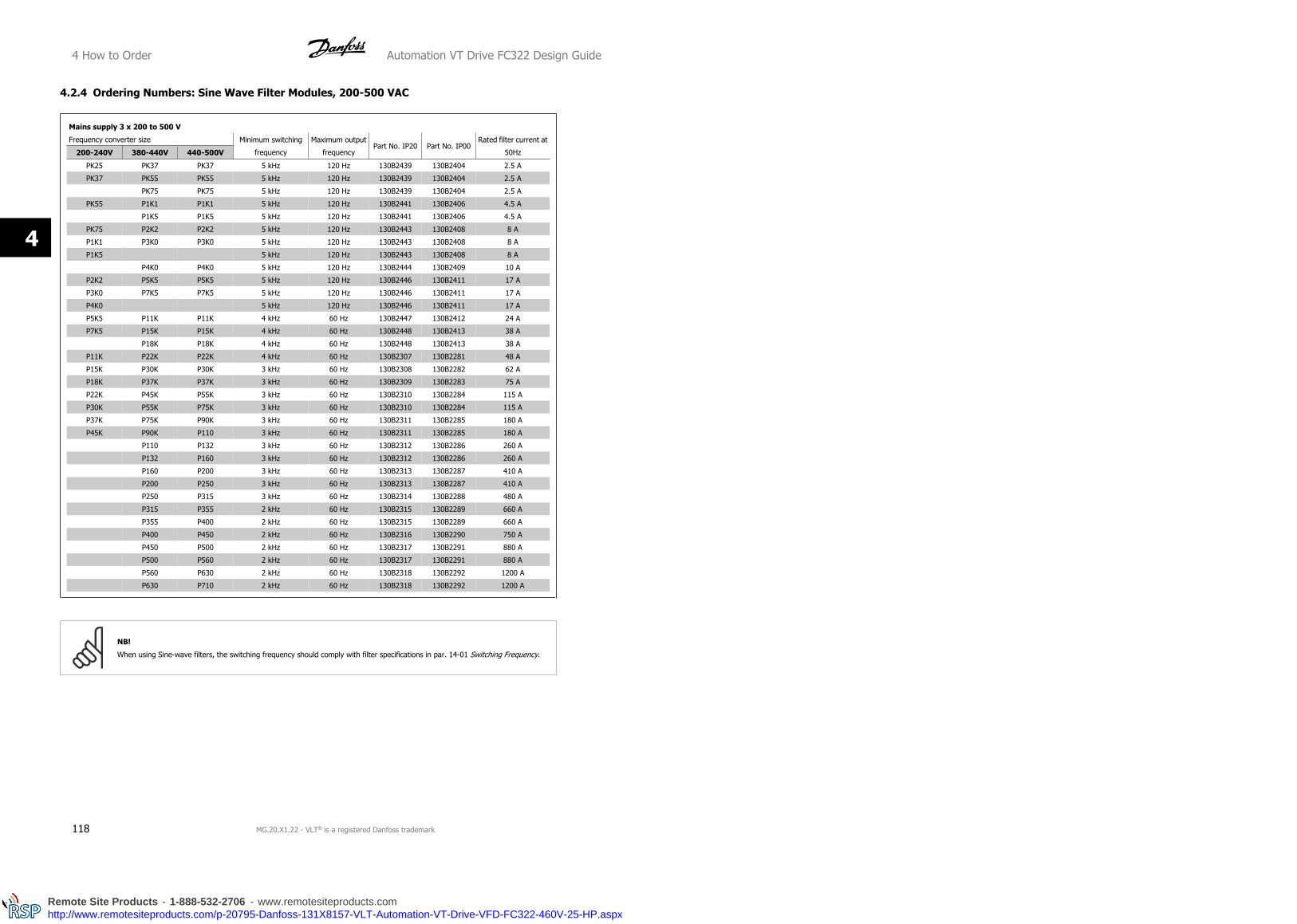
4.2.4 Ordering Numbers: Sine Wave Filter Modules, 200-500 VAC
Mains supply 3 x 200 to 500 V
Frequency converter size Minimum switching
frequency
Maximum output
frequencyPart No. IP20 Part No. IP00
Rated filter current at
50Hz200-240V 380-440V 440-500V
PK25 PK37 PK37 5 kHz 120 Hz 130B2439 130B2404 2.5 A
PK37 PK55 PK55 5 kHz 120 Hz 130B2439 130B2404 2.5 A
PK75 PK75 5 kHz 120 Hz 130B2439 130B2404 2.5 A
PK55 P1K1 P1K1 5 kHz 120 Hz 130B2441 130B2406 4.5 A
P1K5 P1K5 5 kHz 120 Hz 130B2441 130B2406 4.5 A
PK75 P2K2 P2K2 5 kHz 120 Hz 130B2443 130B2408 8 A
P1K1 P3K0 P3K0 5 kHz 120 Hz 130B2443 130B2408 8 A
P1K5 5 kHz 120 Hz 130B2443 130B2408 8 A
P4K0 P4K0 5 kHz 120 Hz 130B2444 130B2409 10 A
P2K2 P5K5 P5K5 5 kHz 120 Hz 130B2446 130B2411 17 A
P3K0 P7K5 P7K5 5 kHz 120 Hz 130B2446 130B2411 17 A
P4K0 5 kHz 120 Hz 130B2446 130B2411 17 A
P5K5 P11K P11K 4 kHz 60 Hz 130B2447 130B2412 24 A
P7K5 P15K P15K 4 kHz 60 Hz 130B2448 130B2413 38 A
P18K P18K 4 kHz 60 Hz 130B2448 130B2413 38 A
P11K P22K P22K 4 kHz 60 Hz 130B2307 130B2281 48 A
P15K P30K P30K 3 kHz 60 Hz 130B2308 130B2282 62 A
P18K P37K P37K 3 kHz 60 Hz 130B2309 130B2283 75 A
P22K P45K P55K 3 kHz 60 Hz 130B2310 130B2284 115 A
P30K P55K P75K 3 kHz 60 Hz 130B2310 130B2284 115 A
P37K P75K P90K 3 kHz 60 Hz 130B2311 130B2285 180 A
P45K P90K P110 3 kHz 60 Hz 130B2311 130B2285 180 A
P110 P132 3 kHz 60 Hz 130B2312 130B2286 260 A
P132 P160 3 kHz 60 Hz 130B2312 130B2286 260 A
P160 P200 3 kHz 60 Hz 130B2313 130B2287 410 A
P200 P250 3 kHz 60 Hz 130B2313 130B2287 410 A
P250 P315 3 kHz 60 Hz 130B2314 130B2288 480 A
P315 P355 2 kHz 60 Hz 130B2315 130B2289 660 A
P355 P400 2 kHz 60 Hz 130B2315 130B2289 660 A
P400 P450 2 kHz 60 Hz 130B2316 130B2290 750 A
P450 P500 2 kHz 60 Hz 130B2317 130B2291 880 A
P500 P560 2 kHz 60 Hz 130B2317 130B2291 880 A
P560 P630 2 kHz 60 Hz 130B2318 130B2292 1200 A
P630 P710 2 kHz 60 Hz 130B2318 130B2292 1200 A
NB!
When using Sine-wave filters, the switching frequency should comply with filter specifications in par. 14-01 Switching Frequency.
4 How to Order Automation VT Drive FC322 Design Guide
118 MG.20.X1.22 - VLT® is a registered Danfoss trademark
4
Remote Site Products - 1-888-532-2706 - www.remotesiteproducts.comhttp://www.remotesiteproducts.com/p-20795-Danfoss-131X8157-VLT-Automation-VT-Drive-VFD-FC322-460V-25-HP.aspx

4.2.5 Ordering Numbers: Sine Wave Filters, 525-600/690 VAC
Frequency converter size [kW] Part No. Danfoss
525-600 V 525-690 VCurrent at 50 Hz
[A]
Minimum switch-
ing frequency
[kHz]
IP00 IP20
0.75 -
13 2 130B2321 130B2341
1.1 -
1.5 -
2.2 -
3.0 -
4.0 -
5.5 -
7.5 -
- 11
28 2 130B2322 130B234211 15
15 18.5
18.5 22
22 3045 2 130B2323 130B2343
30 37
37 4576 2 130B2324 130B2344
45 55
55 75115 2 130B2325 130B2345
75 90
90 110165 2 130B2326 130B2346
110 132
150 160260 2 130B2327 130B2347
180 200
220 250 303 2 130B2329 130B2348
260 315430 1.5 130B2241 130B2270
300 400
375 500 530 1.5 130B2242 130B2271
450 560660 1.5 130B2337 130B2381
480 630
560 710 765 1.5 130B2338 130B2382
670 800940 1.5 130B2339 130B2383
- 900
820 10001320 1.5 130B2340 130B2384
970 1200
Table 4.2: Mains supply 3x525-690 V
Automation VT Drive FC322 Design Guide 4 How to Order
MG.20.X1.22 - VLT® is a registered Danfoss trademark 119
4
Remote Site Products - 1-888-532-2706 - www.remotesiteproducts.comhttp://www.remotesiteproducts.com/p-20795-Danfoss-131X8157-VLT-Automation-VT-Drive-VFD-FC322-460V-25-HP.aspx

4.2.6 Ordering Numbers: du/dt Filters, 380-480 VAC
Mains supply 3x380 to 3x480 V
Frequency converter sizeMinimum switching frequency Maximum output frequency Part No. IP20 Part No. IP00 Rated filter current at 50 Hz
380-440V 441-480V
11 kW 11 kW 4 kHz 60 Hz 130B2396 130B2385 24 A
15 kW 15 kW 4 kHz 60 Hz 130B2397 130B2386 45 A
18.5 kW 18.5 kW 4 kHz 60 Hz 130B2397 130B2386 45 A
22 kW 22 kW 4 kHz 60 Hz 130B2397 130B2386 45 A
30 kW 30 kW 3 kHz 60 Hz 130B2398 130B2387 75 A
37 kW 37 kW 3 kHz 60 Hz 130B2398 130B2387 75 A
45 kW 55 kW 3 kHz 60 Hz 130B2399 130B2388 110 A
55 kW 75 kW 3 kHz 60 Hz 130B2399 130B2388 110 A
75 kW 90 kW 3 kHz 60 Hz 130B2400 130B2389 182 A
90 kW 110 kW 3 kHz 60 Hz 130B2400 130B2389 182 A
110 kW 132 kW 3 kHz 60 Hz 130B2401 130B2390 280 A
132 kW 160 kW 3 kHz 60 Hz 130B2401 130B2390 280 A
160 kW 200 kW 3 kHz 60 Hz 130B2402 130B2391 400 A
200 kW 250 kW 3 kHz 60 Hz 130B2402 130B2391 400 A
250 kW 315 kW 3 kHz 60 Hz 130B2277 130B2275 500 A
315 kW 355 kW 2 kHz 60 Hz 130B2278 130B2276 750 A
355 kW 400 kW 2 kHz 60 Hz 130B2278 130B2276 750 A
400 kW 450 kW 2 kHz 60 Hz 130B2278 130B2276 750 A
450 kW 500 kW 2 kHz 60 Hz 130B2405 130B2393 910 A
500 kW 560 kW 2 kHz 60 Hz 130B2405 130B2393 910 A
560 kW 630 kW 2 kHz 60 Hz 130B2407 130B2394 1500 A
630 kW 710 kW 2 kHz 60 Hz 130B2407 130B2394 1500 A
710 kW 800 kW 2 kHz 60 Hz 130B2407 130B2394 1500 A
800 kW 1000 kW 2 kHz 60 Hz 130B2407 130B2394 1500 A
1000 kW 1100 kW 2 kHz 60 Hz 130B2410 130B2395 2300 A
4 How to Order Automation VT Drive FC322 Design Guide
120 MG.20.X1.22 - VLT® is a registered Danfoss trademark
4
Remote Site Products - 1-888-532-2706 - www.remotesiteproducts.comhttp://www.remotesiteproducts.com/p-20795-Danfoss-131X8157-VLT-Automation-VT-Drive-VFD-FC322-460V-25-HP.aspx

4.2.7 Ordering Numbers: du/dt Filters, 525-600/690 VAC
Frequency converter size [kW] Part No. Danfoss
525-600 V 525-690 V Current [A]
Minimum
switching
frequency
[Hz]
IP00 IP20
- 11
28 4 130B2414 130B242311 15
15 18.5
18.5 22
22 3045 4 130B2415 130B2424
30 37
37 4575 3 130B2416 130B2425
45 55
55 75115 3 130B2417 130B2426
75 90
90 110165 3 130B2418 130B2427
110 132
150 160260 3 130B2419 130B2428
180 200
220 250 310 3 130B2420 130B2429
260 315430 3 130B2235 130B2238
300 400
375 500 530 2 130B2236 130B2239
450 560630 2 130B2280 130B2274
480 630
560 710765 2 130B2421 130B2430
- -
670 800
1350 2 130B2422 130B2431- 900
820 1000
970 1200
Table 4.3: Mains supply 3x525-690 V
Automation VT Drive FC322 Design Guide 4 How to Order
MG.20.X1.22 - VLT® is a registered Danfoss trademark 121
4
Remote Site Products - 1-888-532-2706 - www.remotesiteproducts.comhttp://www.remotesiteproducts.com/p-20795-Danfoss-131X8157-VLT-Automation-VT-Drive-VFD-FC322-460V-25-HP.aspx
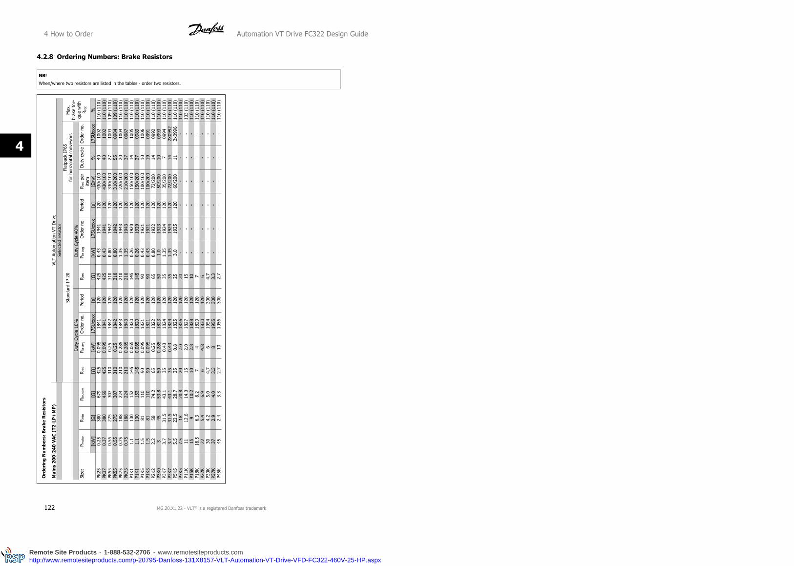
4.2.8 Ordering Numbers: Brake Resistors
NB!
When/where two resistors are listed in the tables - order two resistors.
Ord
erin
g N
um
bers
: B
rake
Res
isto
rs
Mai
ns
200-
240
VA
C (
T2-L
P+
MP
)VL
T Au
tom
atio
n VT
Driv
eSe
lect
ed r
esis
tor
Stan
dard
IP
20Fl
atpa
ck I
P65
for
horiz
onta
l con
veyo
rsM
ax.
brak
e to
r-qu
e w
ithR r
ec
Dut
y Cy
cle
10%
Dut
y Cy
cle
40%
Size
:P m
otor
Rm
inR
br,n
omR r
ecP b
r av
gO
rder
no.
Perio
dR
rec
P br
avg
Ord
er n
o.Pe
riod
R rec
per
item
Dut
y cy
cle
Ord
er n
o.
[kW
][Ω
][Ω
][Ω
][k
W]
175U
xxxx
[s]
[Ω]
[kW
]17
5Uxx
xx[s
][Ω
/w]
%17
5Uxx
xx%
PK25
0.25
380
679
425
0.09
518
4112
042
50.
4319
4112
043
0/10
040
1002
110
(110
)PK
370.
3738
045
942
50.
095
1841
120
425
0.43
1941
120
430/
100
4010
0211
0 (1
10)
PK55
0.55
275
307
310
0.25
1842
120
310
0.80
1942
120
330/
100
2710
0310
9 (1
10)
PK55
0.55
275
307
310
0.25
1842
120
310
0.80
1942
120
310/
200
5509
8410
9 (1
10)
PK75
0.75
188
224
210
0.28
518
4312
021
01.
3519
4312
022
0/10
020
1004
110
(110
)PK
750.
7518
822
421
00.
285
1843
120
210
1.35
1943
120
210/
200
3709
8711
0 (1
10)
P1K1
1.1
130
152
145
0.06
518
2012
014
50.
2619
2012
015
0/10
014
1005
110
(110
)P1
K11.
113
015
214
50.
065
1820
120
145
0.26
1920
120
150/
200
2709
8911
0 (1
10)
P1K5
1.5
8111
090
0.09
518
2112
090
0.43
1921
120
100/
100
1010
0611
0 (1
10)
P1K5
1.5
8111
090
0.09
518
2112
090
0.43
1921
120
100/
200
1909
9111
0 (1
10)
P2K2
2.2
5874
.265
0.25
1822
120
650.
8019
2212
072
/200
1409
9211
0 (1
10)
P3K0
345
53.8
500.
285
1823
120
501.
019
2312
050
/200
1009
9311
0 (1
10)
P3K7
3.7
31.5
43.1
350.
4318
2412
035
1.35
1924
120
35/2
007
0994
110
(110
)P3
K73.
731
.543
.135
0.43
1824
120
351.
3519
2412
072
/200
142X
0992
110
(110
)P5
K55.
522
.528
.725
0.8
1825
120
253.
019
2512
060
/200
112x
0996
110
(110
)P7
K57.
518
20.8
202.
018
2612
020
--
--
--
110
(110
)P1
1K11
12.6
14.0
152.
018
2712
015
--
--
--
103
(110
)P1
5K15
910
.210
2.8
1828
120
10-
--
--
-11
0 (1
10)
P18K
18.5
6.3
8.2
74
1829
120
7-
--
--
-11
0 (1
10)
P22K
225.
46.
96
4.8
1830
120
6-
--
--
-11
0 (1
10)
P30K
304.
25.
04.
76
1954
300
4.7
--
--
--
110
(110
)P3
7K37
2.9
4.0
3.3
819
5530
03.
3-
--
--
-11
0 (1
10)
P45K
452.
43.
32.
710
1956
300
2.7
--
--
--
110
(110
)
4 How to Order Automation VT Drive FC322 Design Guide
122 MG.20.X1.22 - VLT® is a registered Danfoss trademark
4
Remote Site Products - 1-888-532-2706 - www.remotesiteproducts.comhttp://www.remotesiteproducts.com/p-20795-Danfoss-131X8157-VLT-Automation-VT-Drive-VFD-FC322-460V-25-HP.aspx

Ord
erin
g N
um
bers
: B
rake
Res
isto
rs
Mai
ns
380-
480
VA
C (
T4-L
P+
MP
+H
P)
VLT
Auto
mat
ion
VT D
rive
Se
lect
ed r
esis
tor
St
anda
rd I
P 20
Flat
pack
IP6
5fo
r ho
rizon
tal c
onve
yors
Max
. bra
keto
rque
with
R rec
D
uty
Cycl
e 10
%D
uty
Cycl
e 40
%
Size
:P m
otor
R min
Rbr
,nom
R rec
P br
avg
Ord
er n
o.Pe
riod
Rre
cP b
r av
gO
rder
no.
Perio
dR
rec p
er it
emD
uty
cycl
eO
rder
no.
[kW
][Ω
][Ω
][Ω
][k
W]
175U
xxxx
[s]
[Ω]
[kW
]17
5Uxx
xx[s
][Ω
/W]
%17
5Uxx
xx%
PK37
0.37
620
1825
620
0.06
518
4012
062
00.
2619
4012
083
0/10
030
1000
110
(110
)PK
550.
5562
012
2862
00.
065
1840
120
620
0.26
1940
120
830/
100
2010
0011
0 (1
10)
PK75
0.75
485
896
620
0.06
518
4012
062
00.
2619
4012
083
0/10
020
1000
110
(110
)P1
K11.
132
960
862
00.
065
1840
120
620
0.26
1940
120
630
--
110
(110
)P1
K51.
524
044
342
50.
095
1841
120
425
1.0
1941
120
430/
100
1010
0211
0 (1
10)
P1K5
1.5
240
443
425
0.09
518
4112
042
51.
019
4112
043
0/20
020
0983
110
(110
)P2
K22.
216
129
931
00.
2518
4212
031
01.
619
4212
032
0/20
014
0984
110
(110
)P3
K03
117
217
210
0.28
518
4312
021
02.
519
4312
021
5/20
010
0987
110
(110
)P4
K04
86.9
161
150
0.43
1844
120
150
3.7
1944
120
150/
200
1409
8911
0 (1
10)
P4K0
486
.916
115
00.
4318
4412
015
03.
719
4412
030
0/20
07
2X09
8511
0 (1
10)
P5K5
5.5
62.5
115
110
0.6
1845
120
110
4.7
1945
120
120/
200
62X
0990
110
(110
)P7
K57.
545
.383
.780
0.85
1846
120
806.
119
4612
082
/240
52X
0090
110
(110
)P1
1K11
34.9
56.4
402
1848
120
4011
1948
120
--
-11
0 (1
10)
P15K
1525
.340
.940
218
4812
040
1119
4812
0-
--
110
(110
)P1
8K18
.520
.332
.830
2.8
1849
120
3018
1949
120
--
-11
0 (1
10)
P22K
2216
.927
.325
3.5
1850
120
2523
1950
120
--
-11
0 (1
10)
P30K
3013
.220
204
1851
120
2025
1951
120
--
-11
0 (1
10)
P37K
3710
.616
.115
4.8
1852
120
1532
1952
120
--
-11
0 (1
10)
P45K
458.
713
.212
5.5
1853
120
1240
1953
120
--
-11
0 (1
10)
P55K
556.
610
.810
1520
0812
010
6220
0712
0-
--
110
(110
)P7
5K75
6.6
87
1300
6912
07
7200
6812
0-
--
110
(110
)P9
0K90
3.6
75
1819
5930
0-
--
--
--
110
(110
)P1
1011
03
55
1819
5930
0-
--
--
--
110
(110
)P1
3213
22.
55
422
1960
300
--
--
--
-11
0 (1
10)
P160
160
24
3.8
2219
6030
0-
--
--
--
106
(110
)P2
0020
01.
62.
92.
632
1962
300
--
--
--
-11
0 (1
10)
P250
250
1.2
2.4
2.1
3919
6330
0-
--
--
--
110
(110
)P3
1531
51.
21.
92.
139
1963
300
--
--
--
-98
(11
0)P3
5535
51.
21.
7-
--
--
--
--
--
(110
)P4
0040
01.
21.
5-
--
--
--
--
--
(110
)P4
5045
01.
21.
3-
--
--
--
--
--
(110
)P5
0050
01.
21.
3-
--
--
--
--
--
(100
)P5
6056
01.
21.
3-
--
--
--
--
--
(89)
P630
630
1.2
1.3
--
--
--
--
--
-(7
9)P7
1071
01.
21.
3-
--
--
--
--
--
(70)
P800
800
1.2
1.3
--
--
--
--
--
-(6
2)P1
M0
1000
1.2
1.3
--
--
--
--
--
-(5
0)
Automation VT Drive FC322 Design Guide 4 How to Order
MG.20.X1.22 - VLT® is a registered Danfoss trademark 123
4
Remote Site Products - 1-888-532-2706 - www.remotesiteproducts.comhttp://www.remotesiteproducts.com/p-20795-Danfoss-131X8157-VLT-Automation-VT-Drive-VFD-FC322-460V-25-HP.aspx

Ord
erin
g N
um
bers
: B
rake
Res
isto
rs
Mai
ns
525-
690
VA
C (
T7-H
P)
VLT
Auto
mat
ion
VT D
rive
Sele
cted
res
isto
rSt
anda
rd I
P 20
Max
. bra
ke t
or-
que
with
Rre
cD
uty
Cycl
e 10
%D
uty
Cycl
e 40
%
Size
:P m
otor
Rm
inR b
r,no
mR r
ecP b
r av
gO
rder
no.
Perio
dR
rec
P br
avg
Ord
er n
o.Pe
riod
[kW
][Ω
][Ω
][Ω
][k
W]
130B
xxxx
[s]
[Ω]
[kW
]13
0Bxx
xx[s
]%
P37K
3722
.532
.120
5221
1860
020
3221
1860
011
0 (1
10)
P45K
4522
.526
.415
6421
1960
015
3921
1960
011
0 (1
10)
P55K
5518
21.6
1576
2120
600
1547
2120
600
110
(110
)P7
5K75
13.5
15.6
9.8
104
2121
600
9.8
6421
2160
011
0 (1
10)
P90K
908.
813
9.8
126
2122
600
9.8
7721
2260
011
0 (1
10)
P110
110
8.8
10.7
7.3
153
2123
600
7.3
9321
2360
011
0 (1
10)
P132
132
6.6
8.9
4.7
185
2124
600
4.7
113
2124
600
110
(110
)P1
6016
06.
67.
34.
722
421
2560
04.
713
721
2560
011
0 (1
10)
P200
200
4.2
5.9
3.8
147
2X21
2660
03.
890
2X21
2660
011
0 (1
10)
P250
250
4.2
4.7
2.6
173
2X21
2760
02.
610
62X
2127
600
110
(110
)P3
1531
53.
43.
72.
621
22X
2128
600
2.6
130
2X21
2860
010
8 (1
10)
P400
355
2.3
3.3
2.6
722x
1062
300
--
--
110
(110
)P4
5040
02.
32.
92.
672
2x10
6230
0-
--
-11
0 (1
10)
P500
500
2.1
2.3
2.3
902x
1063
300
--
--
110
(110
)P5
6056
01.
92.
12.
110
02x
1064
300
--
--
110
(110
)P6
3063
01.
71.
9-
--
--
--
--
P710
710
1.5
1.7
--
--
--
--
-P8
0080
01.
31.
5-
--
--
--
--
P900
900
1.2
1.3
--
--
--
--
-P1
M0
1000
1.2
1.3
--
--
--
--
-
4 How to Order Automation VT Drive FC322 Design Guide
124 MG.20.X1.22 - VLT® is a registered Danfoss trademark
4
Remote Site Products - 1-888-532-2706 - www.remotesiteproducts.comhttp://www.remotesiteproducts.com/p-20795-Danfoss-131X8157-VLT-Automation-VT-Drive-VFD-FC322-460V-25-HP.aspx

5 How to Install
5.1 Mechanical Installation
Page intentionally left blank!
Automation VT Drive FC322 Design Guide 5 How to Install
MG.20.X1.22 - VLT® is a registered Danfoss trademark 125
5
Remote Site Products - 1-888-532-2706 - www.remotesiteproducts.comhttp://www.remotesiteproducts.com/p-20795-Danfoss-131X8157-VLT-Automation-VT-Drive-VFD-FC322-460V-25-HP.aspx

A2
A3
A5
B1
B2
B3
B4
C1
C2
C3
C4
IP20
/21
IP20
/21
IP55
/66
IP21
/55/
66IP
21/5
5/66
IP20
IP20
IP21
/55/
66IP
21/5
5/66
IP20
IP20
Illus
trat
ion
5.1:
Top
and
bot
tom
mou
ntin
g ho
les.
Illus
trat
ion
5.2:
Top
and
bot
tom
mou
ntin
g ho
les.
(B4
+C3
+C4
onl
y)
Acce
ssor
y ba
gs c
onta
inin
g ne
cess
ary
brac
kets
, scr
ews
and
conn
ecto
rs a
re in
clud
ed w
ith t
he d
rives
upo
n de
liver
y.
All m
easu
rem
ents
in m
m.
5.1
.1M
ech
anic
al F
ron
t V
iew
s5 How to Install Automation VT Drive FC322 Design Guide
126 MG.20.X1.22 - VLT® is a registered Danfoss trademark
5
Remote Site Products - 1-888-532-2706 - www.remotesiteproducts.comhttp://www.remotesiteproducts.com/p-20795-Danfoss-131X8157-VLT-Automation-VT-Drive-VFD-FC322-460V-25-HP.aspx

Mec
han
ical
dim
ensi
ons
Fram
e si
ze (
kW):
A2
A3
A5
B1
B2
B3
B4
C1
C2
C3
C4
200-
240
V
380-
480
V
525-
690
V
0.25
-3.0
0.37
-4.0
- -
3.7
5.5
-7.5
0.75
-7.5
-
0.25
-3.7
0.
75-7
.5
0.37
-7.5
-
5.5-
11
11-1
8.5
11-1
8.5
-
15
22-
30
22-
30
11-
30
5.5-
11
11-1
8.5
11-1
8.5
-
15-1
8.5
22-3
7
22-3
7
-
18.5
-30
37-5
5
37-5
5
-
37-
45
75-
90
75-
90
37-
90
22-3
0
45-5
5
45-5
5
-
37-4
5
75-9
0
75-9
0
-
IP NEM
A
20
Chas
sis
21
Type
1
20
Chas
sis
21
Type
1
55/6
6
Type
12
21/
55/6
6
Type
1/1
2
21/5
5/66
Type
1/1
2
20
Chas
sis
20
Chas
sis
21/5
5/66
Type
1/1
2
21/5
5/66
Type
1/1
2
20
Chas
sis
20
Chas
sis
Hei
ght
(mm
)
Encl
osur
eA*
*24
637
224
637
242
048
065
035
046
068
077
049
060
0
..with
de-
coup
ling
plat
eA2
374
-37
4-
--
-41
959
5-
-63
080
0
Back
pla
teA1
268
375
268
375
420
480
650
399
520
680
770
550
660
Dis
tanc
e be
twee
n m
ount
. hol
esa
257
350
257
350
402
454
624
380
495
648
739
521
631
Wid
th (
mm
)
Encl
osur
eB
9090
130
130
242
242
242
165
231
308
370
308
370
With
one
C o
ptio
nB
130
130
170
170
242
242
242
205
231
308
370
308
370
Back
pla
teB
9090
130
130
242
242
242
165
231
308
370
308
370
Dis
tanc
e be
twee
n m
ount
. hol
esb
7070
110
110
215
210
210
140
200
272
334
270
330
Dep
th (
mm
)
With
out
optio
n A/
BC
205
205
205
205
200
260
260
248
242
310
335
333
333
With
opt
ion
A/B
C*22
022
022
022
020
026
026
026
224
231
033
533
333
3
Scre
w h
oles
(m
m)
c8.
08.
08.
08.
08.
212
128
-12
12-
-
Dia
met
er ø
d11
1111
1112
1919
12-
1919
--
Dia
met
er ø
e5.
55.
55.
55.
56.
59
96.
88.
59.
09.
08.
58.
5
f9
99
99
99
7.9
159.
89.
817
17
Max
wei
ght
(kg)
4.9
5.3
6.6
7.0
1423
2712
23.5
4565
3550
* D
epth
of
encl
osur
e w
ill v
ary
with
diff
eren
t op
tions
inst
alle
d.
** T
he f
ree
spac
e re
quire
men
ts a
re a
bove
and
bel
ow t
he b
are
encl
osur
e he
ight
mea
sure
men
t A.
See
sec
tion
3.2.
3 fo
r fu
rthe
r in
form
atio
n.
5.1
.2M
ech
anic
al D
imen
sion
s
Automation VT Drive FC322 Design Guide 5 How to Install
MG.20.X1.22 - VLT® is a registered Danfoss trademark 127
5
Remote Site Products - 1-888-532-2706 - www.remotesiteproducts.comhttp://www.remotesiteproducts.com/p-20795-Danfoss-131X8157-VLT-Automation-VT-Drive-VFD-FC322-460V-25-HP.aspx
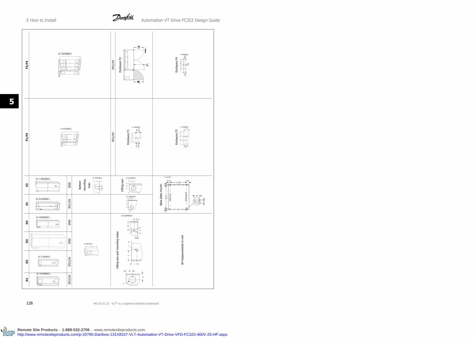
D1
D2
D3
D4
E1E2
F1/F
3F2
/F4
IP21
/54
IP21
/54
IP00
IP00
IP21
/54
IP00
Bott
om
mou
ntin
g
hole
:
Lift
ing
eye
and
mou
ntin
g ho
les:
Lift
ing
eye:
IP21
/54
IP21
/54
Encl
osur
e F1
Encl
osur
e F2
All m
easu
rem
ents
in m
m
Base
pla
te m
ount
:
Encl
osur
e F3
Encl
osur
e F4
5 How to Install Automation VT Drive FC322 Design Guide
128 MG.20.X1.22 - VLT® is a registered Danfoss trademark
5
Remote Site Products - 1-888-532-2706 - www.remotesiteproducts.comhttp://www.remotesiteproducts.com/p-20795-Danfoss-131X8157-VLT-Automation-VT-Drive-VFD-FC322-460V-25-HP.aspx
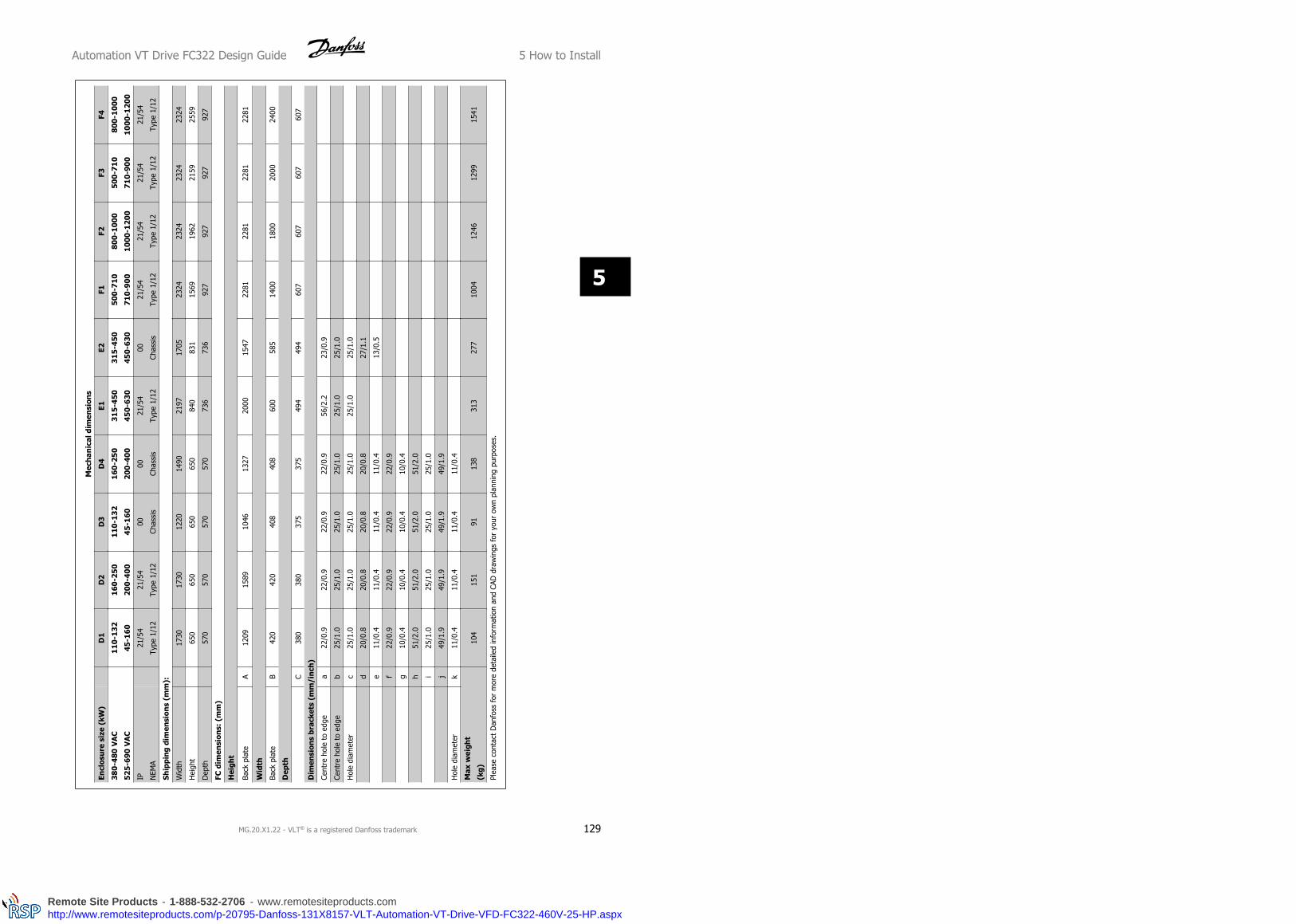
Mec
han
ical
dim
ensi
ons
Encl
osur
e si
ze (
kW)
D1
D2
D3
D4
E1E2
F1F2
F3F4
380-
480
VA
C
525-
690
VA
C
110
-13
2
45-1
60
160
-25
0
200
-40
0
110
-13
2
45-1
60
160
-25
0
200
-40
0
315-
450
450-
630
315
-450
450
-630
500
-71
0
710
-90
0
800-
100
0
1000
-120
0
500-
710
710-
900
800-
100
0
1000
-120
0
IP NEM
A
21/5
4
Type
1/1
2
21/5
4
Type
1/1
2
00
Chas
sis
00
Chas
sis
21/5
4
Type
1/1
2
00
Chas
sis
21/5
4
Type
1/1
2
21/5
4
Type
1/1
2
21/5
4
Type
1/1
2
21/5
4
Type
1/1
2
Ship
pin
g di
men
sion
s (m
m):
Wid
th17
3017
3012
2014
9021
9717
0523
2423
2423
2423
24
Hei
ght
650
650
650
650
840
831
1569
1962
2159
2559
Dep
th57
057
057
057
073
673
692
792
792
792
7
FC d
imen
sion
s: (
mm
)
Hei
ght
Back
pla
teA
1209
1589
1046
1327
2000
1547
2281
2281
2281
2281
Wid
th
Back
pla
teB
420
420
408
408
600
585
1400
1800
2000
2400
Dep
th
C38
038
037
537
549
449
460
760
760
760
7
Dim
ensi
ons
brac
kets
(m
m/i
nch
)
Cent
re h
ole
to e
dge
a22
/0.9
22/0
.922
/0.9
22/0
.956
/2.2
23/0
.9
Cent
re h
ole
to e
dge
b25
/1.0
25/1
.025
/1.0
25/1
.025
/1.0
25/1
.0
Hol
e di
amet
erc
25/1
.025
/1.0
25/1
.025
/1.0
25/1
.025
/1.0
d20
/0.8
20/0
.820
/0.8
20/0
.827
/1.1
e11
/0.4
11/0
.411
/0.4
11/0
.413
/0.5
f22
/0.9
22/0
.922
/0.9
22/0
.9
g10
/0.4
10/0
.410
/0.4
10/0
.4
h51
/2.0
51/2
.051
/2.0
51/2
.0
i25
/1.0
25/1
.025
/1.0
25/1
.0
j49
/1.9
49/1
.949
/1.9
49/1
.9
Hol
e di
amet
erk
11/0
.411
/0.4
11/0
.411
/0.4
Max
wei
ght
(kg)
104
151
9113
831
327
710
0412
4612
9915
41
Plea
se c
onta
ct D
anfo
ss f
or m
ore
deta
iled
info
rmat
ion
and
CAD
dra
win
gs f
or y
our
own
plan
ning
pur
pose
s.
Automation VT Drive FC322 Design Guide 5 How to Install
MG.20.X1.22 - VLT® is a registered Danfoss trademark 129
5
Remote Site Products - 1-888-532-2706 - www.remotesiteproducts.comhttp://www.remotesiteproducts.com/p-20795-Danfoss-131X8157-VLT-Automation-VT-Drive-VFD-FC322-460V-25-HP.aspx
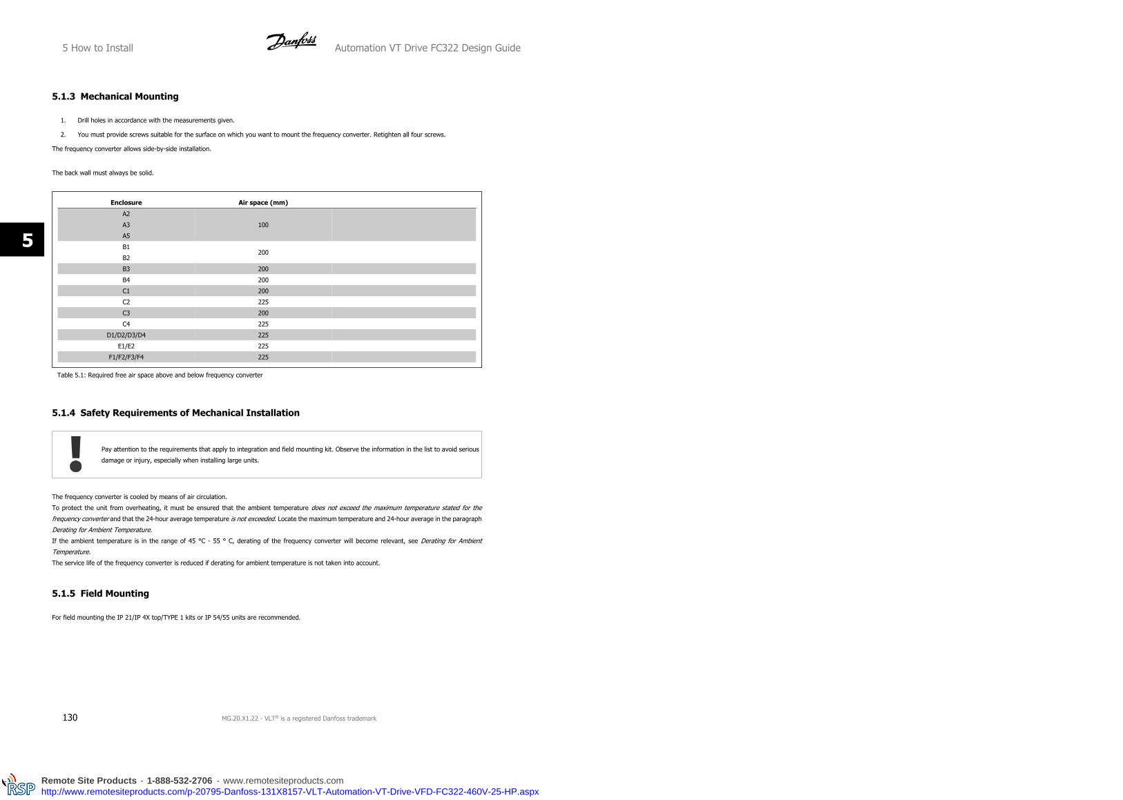
5.1.3 Mechanical Mounting
1. Drill holes in accordance with the measurements given.
2. You must provide screws suitable for the surface on which you want to mount the frequency converter. Retighten all four screws.
The frequency converter allows side-by-side installation.
The back wall must always be solid.
Enclosure Air space (mm)
A2
A3
A5
100
B1
B2200
B3 200
B4 200
C1 200
C2 225
C3 200
C4 225
D1/D2/D3/D4 225
E1/E2 225
F1/F2/F3/F4 225
Table 5.1: Required free air space above and below frequency converter
5.1.4 Safety Requirements of Mechanical Installation
Pay attention to the requirements that apply to integration and field mounting kit. Observe the information in the list to avoid serious
damage or injury, especially when installing large units.
The frequency converter is cooled by means of air circulation.
To protect the unit from overheating, it must be ensured that the ambient temperature does not exceed the maximum temperature stated for the
frequency converter and that the 24-hour average temperature is not exceeded. Locate the maximum temperature and 24-hour average in the paragraph
Derating for Ambient Temperature.
If the ambient temperature is in the range of 45 °C - 55 ° C, derating of the frequency converter will become relevant, see Derating for Ambient
Temperature.
The service life of the frequency converter is reduced if derating for ambient temperature is not taken into account.
5.1.5 Field Mounting
For field mounting the IP 21/IP 4X top/TYPE 1 kits or IP 54/55 units are recommended.
5 How to Install Automation VT Drive FC322 Design Guide
130 MG.20.X1.22 - VLT® is a registered Danfoss trademark
5
Remote Site Products - 1-888-532-2706 - www.remotesiteproducts.comhttp://www.remotesiteproducts.com/p-20795-Danfoss-131X8157-VLT-Automation-VT-Drive-VFD-FC322-460V-25-HP.aspx

5.2 Pre-installation
5.2.1 Planning the Installation Site
NB!
Before performing the installation it is important to plan the installation of the frequency converter. Neglecting this may result in extra
work during and after installation.
Select the best possible operation site by considering the following (see details on the following pages, and the respective Design
Guides):
• Ambient operating temperature
• Installation method
• How to cool the unit
• Position of the frequency converter
• Cable routing
• Ensure the power source supplies the correct voltage and necessary current
• Ensure that the motor current rating is within the maximum current from the frequency converter
• If the frequency converter is without built-in fuses, ensure that the external fuses are rated correctly.
5.2.2 Receiving the Frequency Converter
When receiving the frequency converter please make sure that the packaging is intact, and be aware of any damage that might have occurred to the
unit during transport. In case damage has occurred, contact immediately the shipping company to claim the damage.
5.2.3 Transportation and Unpacking
Before unpacking the frequency converter it is recommended that it is located as close as possible to the final installation site.
Remove the box and handle the frequency converter on the pallet, as long as possible.
NB!
The card box cover contains a drilling master for the mounting holes in the D frames. For the E size, please refer to section Mechanical
Dimensions later in this chapter.
Automation VT Drive FC322 Design Guide 5 How to Install
MG.20.X1.22 - VLT® is a registered Danfoss trademark 131
5
Remote Site Products - 1-888-532-2706 - www.remotesiteproducts.comhttp://www.remotesiteproducts.com/p-20795-Danfoss-131X8157-VLT-Automation-VT-Drive-VFD-FC322-460V-25-HP.aspx

Illustration 5.3: Mounting Template
5.2.4 Lifting
Always lift the frequency converter in the dedicated lifting eyes. For all D and E2 (IP00) frames, use a bar to avoid bending the lifting holes of the frequency
converter.
Illustration 5.4: Recommended lifting method, frame sizes D and E .
NB!
The lifting bar must be able to handle the weight of the frequency converter. See Mechanical Dimensions for the weight of the different
frame sizes. Maximum diameter for bar is 25 cm (1 inch). The angle from the top of the drive to the lifting cable should be 60 degrees
or greater.
5 How to Install Automation VT Drive FC322 Design Guide
132 MG.20.X1.22 - VLT® is a registered Danfoss trademark
5
Remote Site Products - 1-888-532-2706 - www.remotesiteproducts.comhttp://www.remotesiteproducts.com/p-20795-Danfoss-131X8157-VLT-Automation-VT-Drive-VFD-FC322-460V-25-HP.aspx

Illustration 5.5: Recommended lifting method, frame size
F1.
Illustration 5.6: Recommended lifting method, frame size
F2.
Illustration 5.7: Recommended lifting method, frame size
F3.
Automation VT Drive FC322 Design Guide 5 How to Install
MG.20.X1.22 - VLT® is a registered Danfoss trademark 133
5
Remote Site Products - 1-888-532-2706 - www.remotesiteproducts.comhttp://www.remotesiteproducts.com/p-20795-Danfoss-131X8157-VLT-Automation-VT-Drive-VFD-FC322-460V-25-HP.aspx
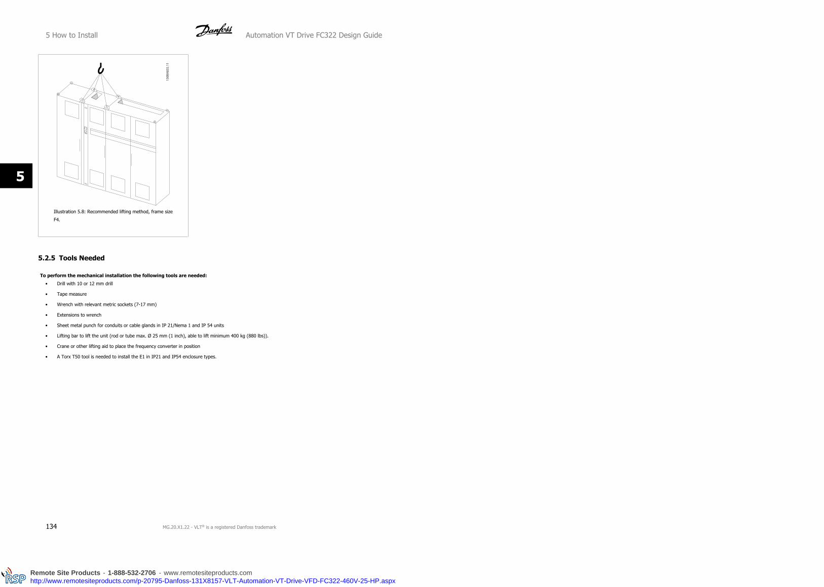
Illustration 5.8: Recommended lifting method, frame size
F4.
5.2.5 Tools Needed
To perform the mechanical installation the following tools are needed:
• Drill with 10 or 12 mm drill
• Tape measure
• Wrench with relevant metric sockets (7-17 mm)
• Extensions to wrench
• Sheet metal punch for conduits or cable glands in IP 21/Nema 1 and IP 54 units
• Lifting bar to lift the unit (rod or tube max. Ø 25 mm (1 inch), able to lift minimum 400 kg (880 lbs)).
• Crane or other lifting aid to place the frequency converter in position
• A Torx T50 tool is needed to install the E1 in IP21 and IP54 enclosure types.
5 How to Install Automation VT Drive FC322 Design Guide
134 MG.20.X1.22 - VLT® is a registered Danfoss trademark
5
Remote Site Products - 1-888-532-2706 - www.remotesiteproducts.comhttp://www.remotesiteproducts.com/p-20795-Danfoss-131X8157-VLT-Automation-VT-Drive-VFD-FC322-460V-25-HP.aspx

5.2.6 General Considerations
Space
Ensure proper space above and below the frequency converter to allow airflow and cable access. In addition space in front of the unit must be considered
to enable opening of the door of the panel.
Illustration 5.9: Space in front of IP21/IP54 enclosure type,
frame size D1 and D2 .
Illustration 5.10: Space in front of IP21/IP54 enclosure type,
frame size E1.
NB!
For frame size F, please see section Mechanical Installation High Power.
Wire access
Ensure that proper cable access is present including necessary bending allowance. As the IP00 enclosure is open to the bottom cables must be fixed to
the back panel of the enclosure where the frequency converter is mounted, i.e. by using cable clamps.
NB!
All cable lugs/ shoes must mount within the width of the terminal bus bar
Automation VT Drive FC322 Design Guide 5 How to Install
MG.20.X1.22 - VLT® is a registered Danfoss trademark 135
5
Remote Site Products - 1-888-532-2706 - www.remotesiteproducts.comhttp://www.remotesiteproducts.com/p-20795-Danfoss-131X8157-VLT-Automation-VT-Drive-VFD-FC322-460V-25-HP.aspx

5.2.7 Cooling and Airflow
Cooling
Cooling can be obtained in different ways, by using the cooling ducts in the bottom and the top of the unit, by taking air in and out the back of the unit
or by combining the cooling possibilities.
Duct cooling
A dedicated option has been developed to optimize installation of IP00/chassis frame frequency converters in Rittal TS8 enclosures utilizing the fan of
the frequency converter for forced air cooling of the backchannel. The air out the top of the enclosure could but ducted outside a facility so the heat loses
from the backchannel are not dissipated within the control room reducing air-conditioning requirements of the facility.
Please see Installation of Duct Cooling Kit in Rittal enclosures, for further information.
Back cooling
The backchannel air can also be ventilated in and out the back of a Rittal TS8 enclosure. This offers a solution where the backchannel could take air from
outside the facility and return the heat loses outside the facility thus reducing air-conditioning requirements.
NB!
A doorfan(s) is required on the Rittal cabinet to remove the loses not contained in the backchannel of the drive. The minimum doorfan(s)
airflow required at the drive maximum ambient for the D3 and D4 is 391 m^3/h (230 cfm). The minimum doorfan(s) airflow required
at the drive maximum ambient for the E2 is 782 m^3/h (460 cfm). If the ambient is below maximum or if additional components, heat
loses, are added within the enclosure a calculation must be made to ensure the proper airflow is provided to cool the inside of the
Rittal enclosure.
Airflow
The necessary airflow over the heat sink must be secured. The flow rate is shown below.
Enclosure protection Frame size Door fan / Top fan airflow Airflow over heatsink
IP21 / NEMA 1
IP54 / NEMA 12
D1 and D2 170 m3/h (100 cfm) 765 m3/h (450 cfm)
E1 340 m3/h (200 cfm) 1444 m3/h (850 cfm)
IP21 / NEMA 1 F1, F2, F3 and F4 700 m3/h (412 cfm)* 985 m3/h (580 cfm)
IP54 / NEMA 12 F1, F2, F3 and F4 525 m3/h (309 cfm)* 985 m3/h (580 cfm)
IP00 / Chassis D3 and D4 255 m3/h (150 cfm) 765 m3/h (450 cfm)
E2 255 m3/h (150 cfm) 1444 m3/h (850 cfm)
* Airflow per fan. Frame size F contain multiple fans.
Table 5.2: Heatsink Air Flow
5.2.8 Gland/Conduit Entry - IP21 (NEMA 1) and IP54 (NEMA12)
Cables are connected through the gland plate from the bottom. Remove the plate and plan where to place the entry for the glands or conduits. Prepare
holes in the marked area on the drawing.
NB!
The gland plate must be fitted to the frequency converter to ensure the specified protection degree, as well as ensuring proper cooling
of the unit. If the gland plate is not mounted, the frequency converter may trip on Alarm 69, Pwr. Card Temp
5 How to Install Automation VT Drive FC322 Design Guide
136 MG.20.X1.22 - VLT® is a registered Danfoss trademark
5
Remote Site Products - 1-888-532-2706 - www.remotesiteproducts.comhttp://www.remotesiteproducts.com/p-20795-Danfoss-131X8157-VLT-Automation-VT-Drive-VFD-FC322-460V-25-HP.aspx

Illustration 5.11: Example of proper installation of the gland plate.
Frame size D1 + D2
Frame size E1
Cable entries viewed from the bottom of the frequency converter - 1) Mains side 2) Motor side
Automation VT Drive FC322 Design Guide 5 How to Install
MG.20.X1.22 - VLT® is a registered Danfoss trademark 137
5
Remote Site Products - 1-888-532-2706 - www.remotesiteproducts.comhttp://www.remotesiteproducts.com/p-20795-Danfoss-131X8157-VLT-Automation-VT-Drive-VFD-FC322-460V-25-HP.aspx

Frame size F1
Frame size F2
Frame size F3
Frame size F4
F1-F4: Cable entries viewed from the bottom of the frequency converter - 1) Place conduits in marked areas
5 How to Install Automation VT Drive FC322 Design Guide
138 MG.20.X1.22 - VLT® is a registered Danfoss trademark
5
Remote Site Products - 1-888-532-2706 - www.remotesiteproducts.comhttp://www.remotesiteproducts.com/p-20795-Danfoss-131X8157-VLT-Automation-VT-Drive-VFD-FC322-460V-25-HP.aspx

Illustration 5.12: Mounting of bottom plate,Frame size E1.
The bottom plate of the E1 frame can be mounted from either in- or outside of the enclosure, allowing flexibility in the installation process, i.e. if mounted
from the bottom the glands and cables can be mounted before the frequency converter is placed on the pedestal.
5.2.9 IP21 Drip Shield Installation (frame size D1 and D2 )
To comply with the IP21 rating, a separate drip shield is to be
installed as explained below:
• Remove the two front screws
• Insert the drip shield and replace screws
• Torque the screws to 5,6 Nm (50 in-lbs)
Illustration 5.13: Drip shield installation.
Automation VT Drive FC322 Design Guide 5 How to Install
MG.20.X1.22 - VLT® is a registered Danfoss trademark 139
5
Remote Site Products - 1-888-532-2706 - www.remotesiteproducts.comhttp://www.remotesiteproducts.com/p-20795-Danfoss-131X8157-VLT-Automation-VT-Drive-VFD-FC322-460V-25-HP.aspx

5.3 Electrical Installation
5.3.1 Cables General
NB!
Cables General
Always comply with national and local regulations on cable cross-sections.
Details of terminal tightening torques.
Power (kW) Torque (Nm)
Enclosure 200-240 V 380-480 V 525-690 V Mains MotorDC connec-
tionBrake Earth Relay
A2 0.25 - 3.0 0.37 - 4.0 1.8 1.8 1.8 1.8 3 0.6
A3 3.7 5.5 - 7.5 0.75 - 7.5 1.8 1.8 1.8 1.8 3 0.6
A5 0.25 - 3.7 0.37 - 7.5 1.1 - 7.5 1.8 1.8 1.8 1.8 3 0.6
B1 5.5 -11 11 - 18 - 1.8 1.8 1.5 1.5 3 0.6
B2 - 1522
30
11 -
30
2.5
4.5
2.5
4.5
3.7
3.7
2.5
4.5
3
3
0.6
0.6
B35.5 -
7.5
11 -
15
-
-1.8 1.8 1.8 1.8
2 -
3
0.5 -
0.6
B411 -
15
18.5 -
30
-
-4.5 4.5 4.5 4.5
2 -
3
0.5 -
0.6
C1 18.5 - 30 37 - 55 - 10 10 10 10 3 0.6
C2 37 - 4575
90
30 -
90
14
24
14
24
14
14
14
14
3
3
0.6
0.6
C318.5 -
22
37 -
45
-
-10 10 10 10
2 -
3
0.5 -
0.6
C4*30
37
55
75
-
-
14
24
14
24
14
24
14
24
2 -
3
0.5 -
0.6
D1/D3 -110
132
110
132
19
19
19
19
9.6
9.6
9.6
9.619 0.6
D2/D4 - 160-250 160-315 19 19 9.6 9.6 19 0.6
E1/E2 - 315-450 355-560 19 19 9.6 9.6 19 0.6
Enclosure 200-240 V 380-480 V 525-690 V Mains MotorDC Con-
nectionBrake Regen Relay
F1/F2/F3/F4 - 500-1000 710-1200 19 19 9.6 9.5 19 0.6
Table 5.3: Tightening of terminals.
* For C4, tigtening torque depends on cable dimensions used - 35-95 mm2 or 120-150 mm2.
5.3.2 Removal of Knockouts for Extra Cables
1. Remove cable entry from the frequency converter (Avoiding foreign parts falling into the frequency converter when removing knockouts)
2. Cable entry has to be supported around the knockout you intend to remove.
3. The knockout can now be removed with a strong mandrel and a hammer.
4. Remove burrs from the hole.
5 How to Install Automation VT Drive FC322 Design Guide
140 MG.20.X1.22 - VLT® is a registered Danfoss trademark
5
Remote Site Products - 1-888-532-2706 - www.remotesiteproducts.comhttp://www.remotesiteproducts.com/p-20795-Danfoss-131X8157-VLT-Automation-VT-Drive-VFD-FC322-460V-25-HP.aspx

5. Mount Cable entry on frequency converter.
5.3.3 Connection to Mains and Earthing
NB!
The plug connector for power can be removed.
1. Make sure the frequency converter is properly earthed. Connect to earth connection (terminal 95). Use screw from the accessory bag.
2. Place plug connector 91, 92, 93 from the accessory bag onto the terminals labelled MAINS at the bottom of the frequency converter.
3. Connect mains wires to the mains plug connector.
The earth connection cable cross section must be at least 10 mm2 or 2 rated mains wires terminated separately according to EN 50178.
The mains connection is fitted to the main switch if this is included.
NB!
Check that mains voltage corresponds to the mains voltage of the frequency converter name plate.
IT Mains
Do not connect 400 V frequency converters with RFI-filters to mains supplies with a voltage between phase and earth of more than
440 V.
For IT mains and delta earth (grounded leg), mains voltage may exceed 440 V between phase and earth.
Illustration 5.14: Terminals for mains and earthing.
Automation VT Drive FC322 Design Guide 5 How to Install
MG.20.X1.22 - VLT® is a registered Danfoss trademark 141
5
Remote Site Products - 1-888-532-2706 - www.remotesiteproducts.comhttp://www.remotesiteproducts.com/p-20795-Danfoss-131X8157-VLT-Automation-VT-Drive-VFD-FC322-460V-25-HP.aspx

Illustration 5.15: How to connect to mains and earthing with disconnector (A5 enclosure).
5.3.4 Motor Cable Connection
NB!
Motor cable must be screened/armoured. If an unscreened / unarmoured cable is used, some EMC requirements are not complied
with. For more information, see EMC specifications.
5 How to Install Automation VT Drive FC322 Design Guide
142 MG.20.X1.22 - VLT® is a registered Danfoss trademark
5
Remote Site Products - 1-888-532-2706 - www.remotesiteproducts.comhttp://www.remotesiteproducts.com/p-20795-Danfoss-131X8157-VLT-Automation-VT-Drive-VFD-FC322-460V-25-HP.aspx

Illustration 5.16: Mounting of decoupling plate.
1. Fasten decoupling plate to the bottom of the frequency converter with screws and washers from the accessory bag.
2. Attach motor cable to terminals 96 (U), 97 (V), 98 (W).
3. Connect to earth connection (terminal 99) on decoupling plate with screws from the accessory bag.
4. Insert terminals 96 (U), 97 (V), 98 (W) and motor cable to terminals labelled MOTOR.
5. Fasten screened cable to decoupling plate with screws and washers from the accessory bag.
All types of three-phase asynchronous standard motors can be connected
to the frequency converter. Normally, small motors are star-connected
(230/400 V, D/Y). Large motors are delta-connected (400/6090 V, D/Y).
Refer to the motor name plate for correct connection mode and voltage.
NB!
In motors without phase insulation paper or other insulation reinforcement suitable for operation with voltage supply (such as a fre-
quency converter), fit a Sine-wave filter on the output of the frequency converter.
Automation VT Drive FC322 Design Guide 5 How to Install
MG.20.X1.22 - VLT® is a registered Danfoss trademark 143
5
Remote Site Products - 1-888-532-2706 - www.remotesiteproducts.comhttp://www.remotesiteproducts.com/p-20795-Danfoss-131X8157-VLT-Automation-VT-Drive-VFD-FC322-460V-25-HP.aspx

No. 96 97 98 Motor voltage 0-100% of mains voltage
U V W
3 wires out of motor
U1 V1 W1 6 wires out of motor, Delta-connected
W2 U2 V2
U1 V1 W1 6 wires out of motor, Star-connected
U2, V2, W2 to be interconnected separately
No. 99 Earth connection
PE
5.3.5 Motor Cables
See section General Specifications for correct dimensioning of motor cable cross-section and length.
• Use a screened/armoured motor cable to comply with EMC emission specifications.
• Keep the motor cable as short as possible to reduce the noise level and leakage currents.
• Connect the motor cable screen to both the de-coupling plate of the frequency converter and to the metal cabinet of the motor.
• Make the screen connections with the largest possible surface area (cable clamp). This is done by using the supplied installation devices in the
frequency converter.
• Avoid mounting with twisted screen ends (pigtails), which will spoil high frequency screening effects.
• If it is necessary to split the screen to install a motor isolator or motor relay, the screen must be continued with the lowest possible HF impedance.
F frame Requirements
F1/F3 requirements: Motor phase cable quantities must be 2, 4, 6, or 8 (multiples of 2, 1 cable is not allowed) to obtain equal amount of wires attached
to both inverter module terminals. The cables are required to be equal length within 10% between the inverter module terminals and the first common
point of a phase. The recommended common point is the motor terminals.
F2/F4 requirements: Motor phase cable quantities must be 3, 6, 9, or 12 (multiples of 3, 2 cables are not allowed) to obtain equal amount of wires
attached to each inverter module terminal. The wires are required to be equal length within 10% between the inverter module terminals and the first
common point of a phase. The recommended common point is the motor terminals.
Output junction box requirements: The length, minimum 2.5 meters, and quantity of cables must be equal from each inverter module to the common
terminal in the junction box.
5.3.6 Electrical Installation of Motor Cables
Screening of cables
Avoid installation with twisted screen ends (pigtails). They spoil the screening effect at higher frequencies.
If it is necessary to break the screen to install a motor isolator or motor contactor, the screen must be continued at the lowest possible HF impedance.
Cable length and cross-section
The frequency converter has been tested with a given length of cable and a given cross-section of that cable. If the cross-section is increased, the cable
capacitance - and thus the leakage current - may increase, and the cable length must be reduced correspondingly.
Switching frequency
When frequency converters are used together with Sine-wave filters to reduce the acoustic noise from a motor, the switching frequency must be set
according to the Sine-wave filter instruction in par. 14-01 Switching Frequency.
Aluminium conductors
Aluminium conductors are not recommended. Terminals can accept aluminium conductors but the conductor surface has to be clean and the oxidation
must be removed and sealed by neutral acid free Vaseline grease before the conductor is connected.
5 How to Install Automation VT Drive FC322 Design Guide
144 MG.20.X1.22 - VLT® is a registered Danfoss trademark
5
Remote Site Products - 1-888-532-2706 - www.remotesiteproducts.comhttp://www.remotesiteproducts.com/p-20795-Danfoss-131X8157-VLT-Automation-VT-Drive-VFD-FC322-460V-25-HP.aspx

Furthermore, the terminal screw must be retightened after two days due to the softness of the aluminium. It is crucial to keep the connection a gas tight
joint, otherwise the aluminium surface will oxidize again.
5.3.7 Fuses
Branch circuit protection:
In order to protect the installation against electrical and fire hazard, all branch circuits in an installation, switch gear, machines etc., must be shortcircuit
and overcurrent protected according to the national/international regulations.
Short circuit protection:
The frequency converter must be protected against short-circuit to avoid electrical or fire hazard. Danfoss recommends using the fuses mentioned in
tables 5.3 and 5.4 to protect service personnel or other equipment in case of an internal failure in the unit. The frequency converter provides full short
circuit protection in case of a short-circuit on the motor output.
Over-current protection:
Provide overload protection to avoid fire hazard due to overheating of the cables in the installation. Over current protection must always be carried out
according to national regulations. The frequency converter is equipped with an internal over current protection that can be used for upstream overload
protection (UL-applications excluded). See par. 4-18. Fuses must be designed for protection in a circuit capable of supplying a maximum of 100,000
Arms (symmetrical), 500 V/600 V maximum.
Non UL compliance:
If UL/cUL is not to be complied with, Danfoss recommends using the fuses mentioned in table 5.2, which will ensure compliance with EN50178:
In case of malfunction, not following the recommendation may result in unnecessary damage to the frequency converter.
Automation VT Drive FC322 Design Guide 5 How to Install
MG.20.X1.22 - VLT® is a registered Danfoss trademark 145
5
Remote Site Products - 1-888-532-2706 - www.remotesiteproducts.comhttp://www.remotesiteproducts.com/p-20795-Danfoss-131X8157-VLT-Automation-VT-Drive-VFD-FC322-460V-25-HP.aspx
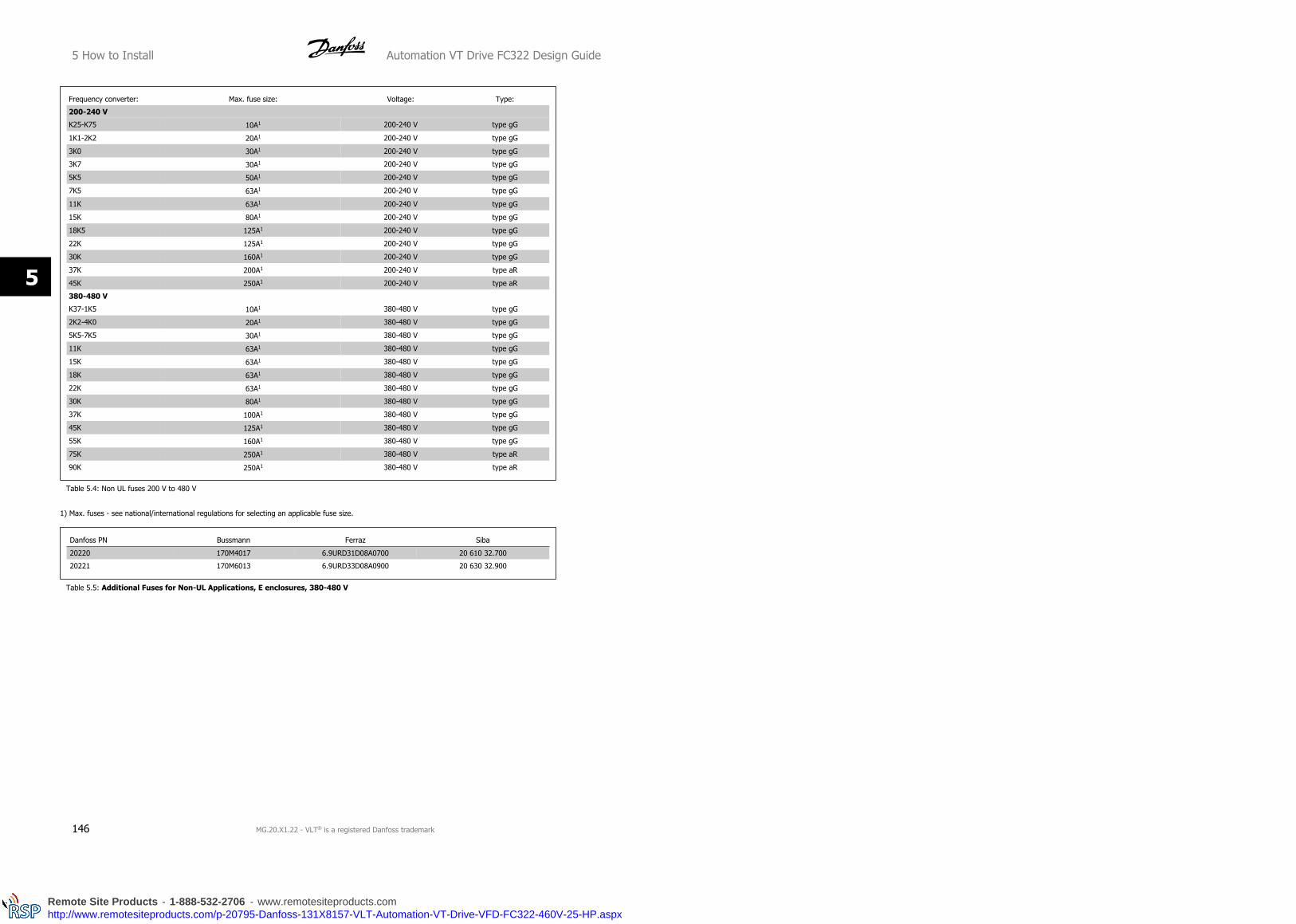
Frequency converter: Max. fuse size: Voltage: Type:
200-240 V
K25-K75 10A1 200-240 V type gG
1K1-2K2 20A1 200-240 V type gG
3K0 30A1 200-240 V type gG
3K7 30A1 200-240 V type gG
5K5 50A1 200-240 V type gG
7K5 63A1 200-240 V type gG
11K 63A1 200-240 V type gG
15K 80A1 200-240 V type gG
18K5 125A1 200-240 V type gG
22K 125A1 200-240 V type gG
30K 160A1 200-240 V type gG
37K 200A1 200-240 V type aR
45K 250A1 200-240 V type aR
380-480 V
K37-1K5 10A1 380-480 V type gG
2K2-4K0 20A1 380-480 V type gG
5K5-7K5 30A1 380-480 V type gG
11K 63A1 380-480 V type gG
15K 63A1 380-480 V type gG
18K 63A1 380-480 V type gG
22K 63A1 380-480 V type gG
30K 80A1 380-480 V type gG
37K 100A1 380-480 V type gG
45K 125A1 380-480 V type gG
55K 160A1 380-480 V type gG
75K 250A1 380-480 V type aR
90K 250A1 380-480 V type aR
Table 5.4: Non UL fuses 200 V to 480 V
1) Max. fuses - see national/international regulations for selecting an applicable fuse size.
Danfoss PN Bussmann Ferraz Siba
20220 170M4017 6.9URD31D08A0700 20 610 32.700
20221 170M6013 6.9URD33D08A0900 20 630 32.900
Table 5.5: Additional Fuses for Non-UL Applications, E enclosures, 380-480 V
5 How to Install Automation VT Drive FC322 Design Guide
146 MG.20.X1.22 - VLT® is a registered Danfoss trademark
5
Remote Site Products - 1-888-532-2706 - www.remotesiteproducts.comhttp://www.remotesiteproducts.com/p-20795-Danfoss-131X8157-VLT-Automation-VT-Drive-VFD-FC322-460V-25-HP.aspx

UL Compliance
VLT Automa-
tion VT DriveBussmann Bussmann Bussmann SIBA Littel fuse
Ferraz-
Shawmut
Ferraz-
Shawmut
200-240 V
kW Type RK1 Type J Type T Type RK1 Type RK1 Type CC Type RK1
K25-1K1 KTN-R10 JKS-10 JJN-10 5017906-010 KLN-R10 ATM-R10 A2K-10R
1K5 KTN-R15 JKS-15 JJN-15 5017906-015 KLN-R15 ATM-R15 A2K-15R
2K2 KTN-R20 JKS-20 JJN-20 5012406-020 KLN-R20 ATM-R20 A2K-20R
3K0 KTN-R25 JKS-25 JJN-25 5012406-025 KLN-R25 ATM-R25 A2K-25R
3K7 KTN-R30 JKS-30 JJN-30 5012406-030 KLN-R30 ATM-R30 A2K-30R
5K5 KTN-R50 JKS-50 JJN-50 5012406-050 KLN-R50 - A2K-50R
7K5 KTN-R50 JKS-60 JJN-60 5012406-050 KLN-R60 - A2K-50R
11K KTN-R60 JKS-60 JJN-60 5014006-063 KLN-R60 A2K-60R
15K KTN-R80 JKS-80 JJN-80 5014006-080 KLN-R80 A2K-80R
18K5 KTN-R125 JKS-150 JJN-125 2028220-125 KLN-R125 A2K-125R
22K KTN-R125 JKS-150 JJN-125 2028220-125 KLN-R125 A2K-125R
30K FWX-150 - - 2028220-150 L25S-150 A25X-150
37K FWX-200 - - 2028220-200 L25S-200 A25X-200
45K FWX-250 - - 2028220-250 L25S-250 A25X-250
Table 5.6: UL fuses 200 - 240 V
VLT Automa-
tion VT DriveBussmann Bussmann Bussmann SIBA Littel fuse
Ferraz-
Shawmut
Ferraz-
Shawmut
380-500 V, 525-600
kW Type RK1 Type J Type T Type RK1 Type RK1 Type CC Type RK1
11K KTS-R40 JKS-40 JJS-40 5014006-040 KLS-R40 - A6K-40R
15K KTS-R40 JKS-40 JJS-40 5014006-040 KLS-R40 - A6K-40R
18K KTS-R50 JKS-50 JJS-50 5014006-050 KLS-R50 - A6K-50R
22K KTS-R60 JKS-60 JJS-60 5014006-063 KLS-R60 - A6K-60R
30K KTS-R80 JKS-80 JJS-80 2028220-100 KLS-R80 - A6K-80R
37K KTS-R100 JKS-100 JJS-100 2028220-125 KLS-R100 A6K-100R
45K KTS-R125 JKS-150 JJS-150 2028220-125 KLS-R125 A6K-125R
55K KTS-R150 JKS-150 JJS-150 2028220-160 KLS-R150 A6K-150R
75K FWH-220 - - 2028220-200 L50S-225 A50-P225
90K FWH-250 - - 2028220-250 L50S-250 A50-P250
Table 5.7: UL fuses 380 - 600 V
KTS-fuses from Bussmann may substitute KTN for 240 V frequency converters.
FWH-fuses from Bussmann may substitute FWX for 240 V frequency converters.
KLSR fuses from LITTEL FUSE may substitute KLNR fuses for 240 V frequency converters.
L50S fuses from LITTEL FUSE may substitute L50S fuses for 240 V frequency converters.
A6KR fuses from FERRAZ SHAWMUT may substitute A2KR for 240 V frequency converters.
A50X fuses from FERRAZ SHAWMUT may substitute A25X for 240 V frequency converters.
Automation VT Drive FC322 Design Guide 5 How to Install
MG.20.X1.22 - VLT® is a registered Danfoss trademark 147
5
Remote Site Products - 1-888-532-2706 - www.remotesiteproducts.comhttp://www.remotesiteproducts.com/p-20795-Danfoss-131X8157-VLT-Automation-VT-Drive-VFD-FC322-460V-25-HP.aspx

Frequency
converterBussmann Bussmann Bussmann SIBA Littel fuse
Ferraz-
Shawmut
Ferraz-
Shawmut
UL Compliance - 200-240 V
kW Type RK1 Type J Type T Type RK1 Type RK1 Type CC Type RK1
K25-K37 KTN-R05 JKS-05 JJN-05 5017906-005 KLN-R005 ATM-R05 A2K-05R
K55-1K1 KTN-R10 JKS-10 JJN-10 5017906-010 KLN-R10 ATM-R10 A2K-10R
1K5 KTN-R15 JKS-15 JJN-15 5017906-015 KLN-R15 ATM-R15 A2K-15R
2K2 KTN-R20 JKS-20 JJN-20 5012406-020 KLN-R20 ATM-R20 A2K-20R
3K0 KTN-R25 JKS-25 JJN-25 5012406-025 KLN-R25 ATM-R25 A2K-25R
3K7 KTN-R30 JKS-30 JJN-30 5012406-030 KLN-R30 ATM-R30 A2K-30R
5K5 KTN-R50 JKS-50 JJN-50 5012406-050 KLN-R50 - A2K-50R
7K5 KTN-R50 JKS-60 JJN-60 5012406-050 KLN-R60 - A2K-50R
11K KTN-R60 JKS-60 JJN-60 5014006-063 KLN-R60 A2K-60R A2K-60R
15K KTN-R80 JKS-80 JJN-80 5014006-080 KLN-R80 A2K-80R A2K-80R
18K5 KTN-R125 JKS-150 JJN-125 2028220-125 KLN-R125 A2K-125R A2K-125R
22K KTN-R125 JKS-150 JJN-125 2028220-125 KLN-R125 A2K-125R A2K-125R
30K FWX-150 - - 2028220-150 L25S-150 A25X-150 A25X-150
37K FWX-200 - - 2028220-200 L25S-200 A25X-200 A25X-200
45K FWX-250 - - 2028220-250 L25S-250 A25X-250 A25X-250
Table 5.8: UL fuses 200 - 240 V
380-500 V, frame sizes D, E and F
The fuses below are suitable for use on a circuit capable of delivering 100,000 Arms (symmetrical), 240V, or 480V, or 500V, or 600V depending on the
drive voltage rating. With the proper fusing the drive Short Circuit Current Rating (SCCR) is 100,000 Arms.
Size/
Type
Bussmann
E1958
JFHR2**
Bussmann
E4273
T/JDDZ**
SIBA
E180276
RKI/JDDZ
LittelFuse
E71611
JFHR2**
Ferraz-
Shawmut
E60314
JFHR2**
Bussmann
E4274
H/JDDZ**
Bussmann
E125085
JFHR2*
Internal
Option
Bussmann
P90K FWH-
300
JJS-
300
2028220-
315
L50S-300 A50-P300 NOS-
300
170M3017 170M3018
P110 FWH-
350
JJS-
350
2028220-
315
L50S-350 A50-P350 NOS-
350
170M3018 170M3018
P132 FWH-
400
JJS-
400
206xx32-
400
L50S-400 A50-P400 NOS-
400
170M4012 170M4016
P160 FWH-
500
JJS-
500
206xx32-
500
L50S-500 A50-P500 NOS-
500
170M4014 170M4016
P200 FWH-
600
JJS-
600
206xx32-
600
L50S-600 A50-P600 NOS-
600
170M4016 170M4016
Table 5.9: Frame size D, Line fuses, 380-500 V
Size/Type Bussmann PN* Rating Ferraz Siba
P250 170M4017 700 A, 700 V 6.9URD31D08A0700 20 610 32.700
P315 170M6013 900 A, 700 V 6.9URD33D08A0900 20 630 32.900
P355 170M6013 900 A, 700 V 6.9URD33D08A0900 20 630 32.900
P400 170M6013 900 A, 700 V 6.9URD33D08A0900 20 630 32.900
Table 5.10: Frame size E, Line fuses, 380-500 V
5 How to Install Automation VT Drive FC322 Design Guide
148 MG.20.X1.22 - VLT® is a registered Danfoss trademark
5
Remote Site Products - 1-888-532-2706 - www.remotesiteproducts.comhttp://www.remotesiteproducts.com/p-20795-Danfoss-131X8157-VLT-Automation-VT-Drive-VFD-FC322-460V-25-HP.aspx

Size/Type Bussmann PN* Rating Siba Internal Bussmann Option
P450 170M7081 1600 A, 700 V 20 695 32.1600 170M7082
P500 170M7081 1600 A, 700 V 20 695 32.1600 170M7082
P560 170M7082 2000 A, 700 V 20 695 32.2000 170M7082
P630 170M7082 2000 A, 700 V 20 695 32.2000 170M7082
P710 170M7083 2500 A, 700 V 20 695 32.2500 170M7083
P800 170M7083 2500 A, 700 V 20 695 32.2500 170M7083
Table 5.11: Frame size F, Line fuses, 380-500 V
Size/Type Bussmann PN* Rating Siba
P450 170M8611 1100 A, 1000 V 20 781 32.1000
P500 170M8611 1100 A, 1000 V 20 781 32.1000
P560 170M6467 1400 A, 700 V 20 681 32.1400
P630 170M6467 1400 A, 700 V 20 681 32.1400
P710 170M8611 1100 A, 1000 V 20 781 32.1000
P800 170M6467 1400 A, 700 V 20 681 32.1400
Table 5.12: Frame size F, Inverter module DC Link Fuses, 380-500 V
*170M fuses from Bussmann shown use the -/80 visual indicator, -TN/80 Type T, -/110 or TN/110 Type T indicator fuses of the same size and amperage
may be substituted for external use
**Any minimum 500 V UL listed fuse with associated current rating may be used to meet UL requirements.
525-690 V, frame sizes D, E and F
Size/Type Bussmann PN* Rating Ferraz Siba
P355 170M4017 700 A, 700 V 6.9URD31D08A0700 20 610 32.700
P400 170M4017 700 A, 700 V 6.9URD31D08A0700 20 610 32.700
P500 170M6013 900 A, 700 V 6.9URD33D08A0900 20 630 32.900
P560 170M6013 900 A, 700 V 6.9URD33D08A0900 20 630 32.900
Table 5.13: Frame size E, 525-690 V
Size/Type Bussmann PN* Rating Siba Internal Bussmann Option
P630 170M7081 1600 A, 700 V 20 695 32.1600 170M7082
P710 170M7081 1600 A, 700 V 20 695 32.1600 170M7082
P800 170M7081 1600 A, 700 V 20 695 32.1600 170M7082
P900 170M7081 1600 A, 700 V 20 695 32.1600 170M7082
P1M0 170M7082 2000 A, 700 V 20 695 32.2000 170M7082
Table 5.14: Frame size F, Line fuses, 525-690 V
Size/Type Bussmann PN* Rating Siba
P630 170M8611 1100 A, 1000 V 20 781 32. 1000
P710 170M8611 1100 A, 1000 V 20 781 32. 1000
P800 170M8611 1100 A, 1000 V 20 781 32. 1000
P900 170M8611 1100 A, 1000 V 20 781 32. 1000
P1M0 170M8611 1100 A, 1000 V 20 781 32. 1000
Table 5.15: Frame size F, Inverter module DC Link Fuses, 525-690 V
*170M fuses from Bussmann shown use the -/80 visual indicator, -TN/80 Type T, -/110 or TN/110 Type T indicator fuses of the same size and amperage
may be substituted for external use.
Automation VT Drive FC322 Design Guide 5 How to Install
MG.20.X1.22 - VLT® is a registered Danfoss trademark 149
5
Remote Site Products - 1-888-532-2706 - www.remotesiteproducts.comhttp://www.remotesiteproducts.com/p-20795-Danfoss-131X8157-VLT-Automation-VT-Drive-VFD-FC322-460V-25-HP.aspx

Suitable for use on a circuit capable of delivering not more than 100 000 rms symmetrical amperes, 500/600/690 Volts maximum when protected by the
above fuses.
5 How to Install Automation VT Drive FC322 Design Guide
150 MG.20.X1.22 - VLT® is a registered Danfoss trademark
5
Remote Site Products - 1-888-532-2706 - www.remotesiteproducts.comhttp://www.remotesiteproducts.com/p-20795-Danfoss-131X8157-VLT-Automation-VT-Drive-VFD-FC322-460V-25-HP.aspx

5.3.8 Access to Control Terminals
All terminals to the control cables are located underneath the terminal cover on the front of the frequency converter. Remove the terminal cover by means
of a screwdriver (see illustration).
Illustration 5.17: Frame sizes A1, A2, A3,B3, B4, C3 and C4
Illustration 5.18: Frame sizes A5, B1, B2, C1 and C2
5.3.9 Control Terminals
Drawing reference numbers:
1. 10 pole plug digital I/O.
2. 3 pole plug RS485 Bus.
3. 6 pole analog I/O.
4. USB Connection.
Illustration 5.19: Control terminals (all enclosures)
Automation VT Drive FC322 Design Guide 5 How to Install
MG.20.X1.22 - VLT® is a registered Danfoss trademark 151
5
Remote Site Products - 1-888-532-2706 - www.remotesiteproducts.comhttp://www.remotesiteproducts.com/p-20795-Danfoss-131X8157-VLT-Automation-VT-Drive-VFD-FC322-460V-25-HP.aspx

5.3.10 Control Cable Terminals
To mount the cable to the terminal:
1. Strip isolation of 9-10 mm
2. Insert a screw driver1) in the square hole.
3. Insert the cable in the adjacent circular hole.
4. Remove the screw driver. The cable is now mounted to the ter-
minal.
To remove the cable from the terminal:
1. Insert a screw driver1) in the square hole.
2. Pull out the cable.
1) Max. 0.4 x 2.5 mm
1.
2. 3.
5 How to Install Automation VT Drive FC322 Design Guide
152 MG.20.X1.22 - VLT® is a registered Danfoss trademark
5
Remote Site Products - 1-888-532-2706 - www.remotesiteproducts.comhttp://www.remotesiteproducts.com/p-20795-Danfoss-131X8157-VLT-Automation-VT-Drive-VFD-FC322-460V-25-HP.aspx

Illustration 5.20: Assembling of IP21 / IP55 / NEMA TYPE 12 housing with mains disconnector.
5.3.11 Basic Wiring Example
1. Mount terminals from the accessory bag to the front of the fre-
quency converter.
2. Connect terminals 18 and 27 to +24 V (terminal 12/13)
Default settings:
18 = Start
27 = stop inverse
Illustration 5.21: Terminal 37 available with Safe Stop Func-
tion only!
Automation VT Drive FC322 Design Guide 5 How to Install
MG.20.X1.22 - VLT® is a registered Danfoss trademark 153
5
Remote Site Products - 1-888-532-2706 - www.remotesiteproducts.comhttp://www.remotesiteproducts.com/p-20795-Danfoss-131X8157-VLT-Automation-VT-Drive-VFD-FC322-460V-25-HP.aspx

5.3.12 Control Cable Length
Digital in / digital out
Dependent on what kind of electronics is being used, the maximum cable impedance may be calculated based on the 4 kΩ frequency converter input
impedance.
Analog in / analog out
Again the electronics used puts a limitation on the cable length.
NB!
Noise is always a factor to be reckoned with.
5.3.13 Electrical Installation, Control Cables
Illustration 5.22: Terminal 37: Safe Stop input available with Safe Stop Function only!
5 How to Install Automation VT Drive FC322 Design Guide
154 MG.20.X1.22 - VLT® is a registered Danfoss trademark
5
Remote Site Products - 1-888-532-2706 - www.remotesiteproducts.comhttp://www.remotesiteproducts.com/p-20795-Danfoss-131X8157-VLT-Automation-VT-Drive-VFD-FC322-460V-25-HP.aspx

Very long control cables and analog signals may in rare cases and depending on installation result in 50/60 Hz earth loops due to noise from mains supply
cables.
If this occurs, you may have to break the screen or insert a 100 nF capacitor between screen and chassis.
The digital and analog in- and outputs must be connected separately to the VLT Automation VT Drive common inputs (terminal 20, 55, 39) to avoid
ground currents from both groups to affect other groups. For example, switching on the digital input may disturb the analog input signal.
NB!
Control cables must be screened/armoured.
1. Use a clamp from the accessory bag to connect the screen to
the frequency converter de-coupling plate for control cables.
See section entitled Earthing of Screened/Armoured Control Cables for
the correct termination of control cables.
5.3.14 Switches S201, S202, and S801
Switches S201 (A53) and S202 (A54) are used to select a current (0-20
mA) or a voltage (0 to 10 V) configuration of the analog input terminals
53 and 54 respectively.
Switch S801 (BUS TER.) can be used to enable termination on the RS-485
port (terminals 68 and 69).
See drawing Diagram showing all electrical terminals in section Electrical
Installation.
Default setting:
S201 (A53) = OFF (voltage input)
S202 (A54) = OFF (voltage input)
S801 (Bus termination) = OFF
NB!
It is recommended to only change switch position at power off.
Automation VT Drive FC322 Design Guide 5 How to Install
MG.20.X1.22 - VLT® is a registered Danfoss trademark 155
5
Remote Site Products - 1-888-532-2706 - www.remotesiteproducts.comhttp://www.remotesiteproducts.com/p-20795-Danfoss-131X8157-VLT-Automation-VT-Drive-VFD-FC322-460V-25-HP.aspx

5.4 Connections - Frame sizes D, E and F
5.4.1 Power Connections
Cabling and Fusing
NB!
Cables General
All cabling must comply with national and local regulations on cable cross-sections and ambient temperature. Copper (75°C) conductors
are recommended.
The power cable connections are situated as shown below. Dimensioning of cable cross section must be done in accordance with the current ratings and
local legislation. See the Specifications section for details.
For protection of the frequency converter, the recommended fuses must be used or the unit must be with built-in fuses. Recommended fuses can be
seen in the tables of the fuse section. Always ensure that proper fusing is made according to local regulation.
The mains connection is fitted to the mains switch if this is included.
5 How to Install Automation VT Drive FC322 Design Guide
156 MG.20.X1.22 - VLT® is a registered Danfoss trademark
5
Remote Site Products - 1-888-532-2706 - www.remotesiteproducts.comhttp://www.remotesiteproducts.com/p-20795-Danfoss-131X8157-VLT-Automation-VT-Drive-VFD-FC322-460V-25-HP.aspx

NB!
The motor cable must be screened/armoured. If an unscreened/unarmoured cable is used, some EMC requirements are not complied
with. Use a screened/armoured motor cable to comply with EMC emission specifications. For more information, see EMC specifica-
tions in the Design Guide.
See section General Specifications for correct dimensioning of motor cable cross-section and length.
Screening of cables:
Avoid installation with twisted screen ends (pigtails). They spoil the screening effect at higher frequencies. If it is necessary to break the screen to install
a motor isolator or motor contactor, the screen must be continued at the lowest possible HF impedance.
Connect the motor cable screen to both the de-coupling plate of the frequency converter and to the metal housing of the motor.
Make the screen connections with the largest possible surface area (cable clamp). This is done by using the supplied installation devices within the
frequency converter.
Cable-length and cross-section:
The frequency converter has been EMC tested with a given length of cable. Keep the motor cable as short as possible to reduce the noise level and
leakage currents.
Switching frequency:
When frequency converters are used together with Sine-wave filters to reduce the acoustic noise from a motor, the switching frequency must be set
according to the instruction in par. 14-01 Switching Frequency.
Term. no. 96 97 98 99
U V W PE1) Motor voltage 0-100% of mains voltage.
3 wires out of motor
U1 V1 W1PE1)
Delta-connected
W2 U2 V2 6 wires out of motor
U1 V1 W1 PE1) Star-connected U2, V2, W2
U2, V2 and W2 to be interconnected separately.
1)Protected Earth Connection
NB!
In motors without phase insulation paper or other in-
sulation reinforcement suitable for operation with volt-
age supply (such as a frequency converter), fit a Sine-
wave filter on the output of the frequency converter.
Automation VT Drive FC322 Design Guide 5 How to Install
MG.20.X1.22 - VLT® is a registered Danfoss trademark 157
5
Remote Site Products - 1-888-532-2706 - www.remotesiteproducts.comhttp://www.remotesiteproducts.com/p-20795-Danfoss-131X8157-VLT-Automation-VT-Drive-VFD-FC322-460V-25-HP.aspx

Illustration 5.23: Compact IP 21 (NEMA 1) and IP 54 (NEMA 12), frame size D1
Illustration 5.24: Compact IP 21 (NEMA 1) and IP 54 (NEMA 12) with disconnect, fuse and RFI filter, frame size D2
5 How to Install Automation VT Drive FC322 Design Guide
158 MG.20.X1.22 - VLT® is a registered Danfoss trademark
5
Remote Site Products - 1-888-532-2706 - www.remotesiteproducts.comhttp://www.remotesiteproducts.com/p-20795-Danfoss-131X8157-VLT-Automation-VT-Drive-VFD-FC322-460V-25-HP.aspx

1) AUX Relay 5) Brake
01 02 03 -R +R
04 05 06 81 82
2) Temp Switch 6) SMPS Fuse (see fuse tables for part number)
106 104 105 7) AUX Fan
3) Line 100 101 102 103
R S T L1 L2 L1 L2
91 92 93 8) Fan Fuse (see fuse tables for part number)
L1 L2 L3 9) Mains ground
4) Load sharing 10) Motor
-DC +DC U V W
88 89 96 97 98
T1 T2 T3
Illustration 5.25: Compact IP 00 (Chassis), frame size D3
Automation VT Drive FC322 Design Guide 5 How to Install
MG.20.X1.22 - VLT® is a registered Danfoss trademark 159
5
Remote Site Products - 1-888-532-2706 - www.remotesiteproducts.comhttp://www.remotesiteproducts.com/p-20795-Danfoss-131X8157-VLT-Automation-VT-Drive-VFD-FC322-460V-25-HP.aspx

Illustration 5.26: Compact IP 00 (Chassis) with disconnect, fuse and RFI filter, frame size D4
1) AUX Relay 5) Brake
01 02 03 -R +R
04 05 06 81 82
2) Temp Switch 6) SMPS Fuse (see fuse tables for part number)
106 104 105 7) AUX Fan
3) Line 100 101 102 103
R S T L1 L2 L1 L2
91 92 93 8) Fan Fuse (see fuse tables for part number)
L1 L2 L3 9) Mains ground
4) Load sharing 10) Motor
-DC +DC U V W
88 89 96 97 98
T1 T2 T3
5 How to Install Automation VT Drive FC322 Design Guide
160 MG.20.X1.22 - VLT® is a registered Danfoss trademark
5
Remote Site Products - 1-888-532-2706 - www.remotesiteproducts.comhttp://www.remotesiteproducts.com/p-20795-Danfoss-131X8157-VLT-Automation-VT-Drive-VFD-FC322-460V-25-HP.aspx

Illustration 5.27: Position of earth terminals IP00, frame
sizes D
Illustration 5.28: Position of earth terminals IP21 (NEMA
type 1) and IP54 (NEMA type 12)
NB!
D2 and D4 shown as examples. D1 and D3 are equivalent.
Automation VT Drive FC322 Design Guide 5 How to Install
MG.20.X1.22 - VLT® is a registered Danfoss trademark 161
5
Remote Site Products - 1-888-532-2706 - www.remotesiteproducts.comhttp://www.remotesiteproducts.com/p-20795-Danfoss-131X8157-VLT-Automation-VT-Drive-VFD-FC322-460V-25-HP.aspx

Illustration 5.29: Compact IP 21 (NEMA 1) and IP 54 (NEMA 12) frame size E1
Illustration 5.30: Compact IP 00 (Chassis) with disconnect, fuse and RFI filter, frame size E2
5 How to Install Automation VT Drive FC322 Design Guide
162 MG.20.X1.22 - VLT® is a registered Danfoss trademark
5
Remote Site Products - 1-888-532-2706 - www.remotesiteproducts.comhttp://www.remotesiteproducts.com/p-20795-Danfoss-131X8157-VLT-Automation-VT-Drive-VFD-FC322-460V-25-HP.aspx

1) AUX Relay 5) Load sharing
01 02 03 -DC +DC
04 05 06 88 89
2) Temp Switch 6) SMPS Fuse (see fuse tables for part number)
106 104 105 7) Fan Fuse (see fuse tables for part number)
3) Line 8) AUX Fan
R S T 100 101 102 103
91 92 93 L1 L2 L1 L2
L1 L2 L3 9) Mains ground
4) Brake 10) Motor
-R +R U V W
81 82 96 97 98
T1 T2 T3
Illustration 5.31: Position of earth terminals IP00, frame sizes E
Automation VT Drive FC322 Design Guide 5 How to Install
MG.20.X1.22 - VLT® is a registered Danfoss trademark 163
5
Remote Site Products - 1-888-532-2706 - www.remotesiteproducts.comhttp://www.remotesiteproducts.com/p-20795-Danfoss-131X8157-VLT-Automation-VT-Drive-VFD-FC322-460V-25-HP.aspx

Illustration 5.32: Rectifier Cabinet, frame size F1, F2, F3 and F4
1) 24 V DC, 5 A 5) Loadsharing
T1 Output Taps -DC +DC
Temp Switch 88 89
106 104 105 6) Control Transformer Fuses (2 or 4 pieces). See fuse tables for part numbers
2) Manual Motor Starters 7) SMPS Fuse. See fuse tables for part numbers
3) 30 A Fuse Protected Power Terminals 8) Manual Motor Controller fuses (3 or 6 pieces). See fuse tables for part numbers
4) Line 9) Line Fuses, F1 and F2 frame (3 pieces). See fuse tables for part numbers
R S T 10) 30 Amp Fuse Protected Power fuses
L1 L2 L3
5 How to Install Automation VT Drive FC322 Design Guide
164 MG.20.X1.22 - VLT® is a registered Danfoss trademark
5
Remote Site Products - 1-888-532-2706 - www.remotesiteproducts.comhttp://www.remotesiteproducts.com/p-20795-Danfoss-131X8157-VLT-Automation-VT-Drive-VFD-FC322-460V-25-HP.aspx

Illustration 5.33: Inverter Cabinet, frame size F1 and F3
Automation VT Drive FC322 Design Guide 5 How to Install
MG.20.X1.22 - VLT® is a registered Danfoss trademark 165
5
Remote Site Products - 1-888-532-2706 - www.remotesiteproducts.comhttp://www.remotesiteproducts.com/p-20795-Danfoss-131X8157-VLT-Automation-VT-Drive-VFD-FC322-460V-25-HP.aspx

1) External Temperature Monitoring 6) Motor
2) AUX Relay U V W
01 02 03 96 97 98
04 05 06 T1 T2 T3
3) NAMUR 7) NAMUR Fuse. See fuse tables for part numbers
4) AUX Fan 8) Fan Fuses. See fuse tables for part numbers
100 101 102 103 9) SMPS Fuses. See fuse tables for part numbers
L1 L2 L1 L2
5) Brake
-R +R
81 82
Illustration 5.34: Inverter Cabinet, frame size F2 and F4
5 How to Install Automation VT Drive FC322 Design Guide
166 MG.20.X1.22 - VLT® is a registered Danfoss trademark
5
Remote Site Products - 1-888-532-2706 - www.remotesiteproducts.comhttp://www.remotesiteproducts.com/p-20795-Danfoss-131X8157-VLT-Automation-VT-Drive-VFD-FC322-460V-25-HP.aspx

1) External Temperature Monitoring 6) Motor
2) AUX Relay U V W
01 02 03 96 97 98
04 05 06 T1 T2 T3
3) NAMUR 7) NAMUR Fuse. See fuse tables for part numbers
4) AUX Fan 8) Fan Fuses. See fuse tables for part numbers
100 101 102 103 9) SMPS Fuses. See fuse tables for part numbers
L1 L2 L1 L2
5) Brake
-R +R
81 82
Automation VT Drive FC322 Design Guide 5 How to Install
MG.20.X1.22 - VLT® is a registered Danfoss trademark 167
5
Remote Site Products - 1-888-532-2706 - www.remotesiteproducts.comhttp://www.remotesiteproducts.com/p-20795-Danfoss-131X8157-VLT-Automation-VT-Drive-VFD-FC322-460V-25-HP.aspx

Illustration 5.35: Options Cabinet, frame size F3 and F4
5 How to Install Automation VT Drive FC322 Design Guide
168 MG.20.X1.22 - VLT® is a registered Danfoss trademark
5
Remote Site Products - 1-888-532-2706 - www.remotesiteproducts.comhttp://www.remotesiteproducts.com/p-20795-Danfoss-131X8157-VLT-Automation-VT-Drive-VFD-FC322-460V-25-HP.aspx

1) Pilz Relay Terminal 4) Safety Relay Coil Fuse with PILS Relay
2) RCD or IRM Terminal See fuse tables for part numbers
3) Mains 5) Line Fuses, F3 and F4 (3 pieces)
R S T See fuse tables for part numbers
91 92 93 6) Contactor Relay Coil (230 VAC). N/C and N/O Aux Contacts
L1 L2 L3 7) Circuit Breaker Shunt Trip Control Terminals (230 VAC or 230 VDC)
5.4.2 Shielding against Electrical Noise
Before mounting the mains power cable, mount the EMC metal cover to ensure best EMC performance.
NOTE: The EMC metal cover is only included in units with an RFI filter.
Illustration 5.36: Mounting of EMC shield.
5.4.3 External Fan Supply
In case the frequency converter is supplied by DC or if the fan must run independently of the power supply, an external power supply can be applied.
The connection is made on the power card.
Terminal No. Function
100, 101
102, 103
Auxiliary supply S, T
Internal supply S, T
The connector located on the power card provides the connection of line voltage for the cooling fans. The fans are connected from factory to be supplied
form a common AC line (jumpers between 100-102 and 101-103). If external supply is needed, the jumpers are removed and the supply is connected
to terminals 100 and 101. A 5 Amp fuse should be used for protection. In UL applications this should be LittleFuse KLK-5 or equivalent.
Automation VT Drive FC322 Design Guide 5 How to Install
MG.20.X1.22 - VLT® is a registered Danfoss trademark 169
5
Remote Site Products - 1-888-532-2706 - www.remotesiteproducts.comhttp://www.remotesiteproducts.com/p-20795-Danfoss-131X8157-VLT-Automation-VT-Drive-VFD-FC322-460V-25-HP.aspx

5.5 Disconnectors, Circuit Breakers and Contactors
5.5.1 Mains Disconnectors
Assembling of IP55 / NEMA Type 12 (A5 housing) with mains disconnector
Mains switch is placed on left side on frame sizes B1, B2, C1 and C2 . Mains switch on A5 frames is placed on right side
Frame size: Type:
A5 Kraus&Naimer KG20A T303
B1 Kraus&Naimer KG64 T303
B2 Kraus&Naimer KG64 T303
C1 30 kW High Overload Kraus&Naimer KG100 T303
C1 37-45 kW High Overload Kraus&Naimer KG105 T303
C2 55 kW High Overload Kraus&Naimer KG160 T303
C2 75 kW High Overload Kraus&Naimer KG250 T303
5.5.2 Mains Disconnectors - Frame Size D, E and F
Frame size Power & Voltage Type
D1/D3 P90K-P110 380-500V & P90K-P132 525-690V ABB OETL-NF200A
D2/D4 P132-P200 380-500V & P160-P315 525-690V ABB OETL-NF400A
E1/E2 P250 380-500V & P355-P560500HP-750HP 525-690V ABB OETL-NF600A
E1/E2 P315-P400 380-500V ABB OETL-NF800A
F3 P450 380-500V & P630-P710 525-690V Merlin Gerin NPJF36000S12AAYP*
F4 P500-P630 380-500V & P800 525-690V Merlin Gerin NRK36000S20AAYP*
F4 P710-P800 380-500V & P900-P1M0 525-690V Merlin Gerin NRK36000S20AAYP*
* Drive SCCR rating maybe less than 100 kA when this option is added. See the drive label for SCCR rating.
5 How to Install Automation VT Drive FC322 Design Guide
170 MG.20.X1.22 - VLT® is a registered Danfoss trademark
5
Remote Site Products - 1-888-532-2706 - www.remotesiteproducts.comhttp://www.remotesiteproducts.com/p-20795-Danfoss-131X8157-VLT-Automation-VT-Drive-VFD-FC322-460V-25-HP.aspx
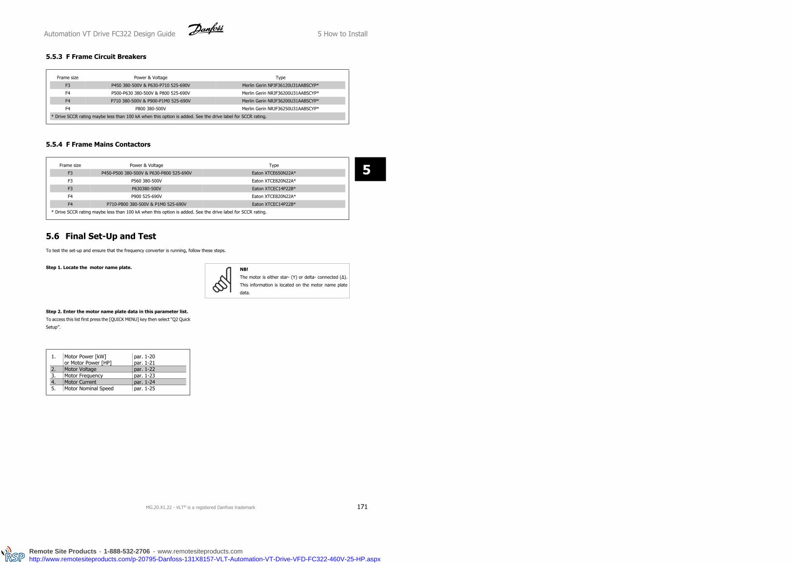
5.5.3 F Frame Circuit Breakers
Frame size Power & Voltage Type
F3 P450 380-500V & P630-P710 525-690V Merlin Gerin NPJF36120U31AABSCYP*
F4 P500-P630 380-500V & P800 525-690V Merlin Gerin NRJF36200U31AABSCYP*
F4 P710 380-500V & P900-P1M0 525-690V Merlin Gerin NRJF36200U31AABSCYP*
F4 P800 380-500V Merlin Gerin NRJF36250U31AABSCYP*
* Drive SCCR rating maybe less than 100 kA when this option is added. See the drive label for SCCR rating.
5.5.4 F Frame Mains Contactors
Frame size Power & Voltage Type
F3 P450-P500 380-500V & P630-P800 525-690V Eaton XTCE650N22A*
F3 P560 380-500V Eaton XTCE820N22A*
F3 P630380-500V Eaton XTCEC14P22B*
F4 P900 525-690V Eaton XTCE820N22A*
F4 P710-P800 380-500V & P1M0 525-690V Eaton XTCEC14P22B*
* Drive SCCR rating maybe less than 100 kA when this option is added. See the drive label for SCCR rating.
5.6 Final Set-Up and TestTo test the set-up and ensure that the frequency converter is running, follow these steps.
Step 1. Locate the motor name plate. NB!
The motor is either star- (Y) or delta- connected (Δ).
This information is located on the motor name plate
data.
Step 2. Enter the motor name plate data in this parameter list.
To access this list first press the [QUICK MENU] key then select “Q2 Quick
Setup”.
1. Motor Power [kW]or Motor Power [HP]
par. 1-20par. 1-21
2. Motor Voltage par. 1-223. Motor Frequency par. 1-234. Motor Current par. 1-245. Motor Nominal Speed par. 1-25
Automation VT Drive FC322 Design Guide 5 How to Install
MG.20.X1.22 - VLT® is a registered Danfoss trademark 171
5
Remote Site Products - 1-888-532-2706 - www.remotesiteproducts.comhttp://www.remotesiteproducts.com/p-20795-Danfoss-131X8157-VLT-Automation-VT-Drive-VFD-FC322-460V-25-HP.aspx

5 How to Install Automation VT Drive FC322 Design Guide
172 MG.20.X1.22 - VLT® is a registered Danfoss trademark
5
Remote Site Products - 1-888-532-2706 - www.remotesiteproducts.comhttp://www.remotesiteproducts.com/p-20795-Danfoss-131X8157-VLT-Automation-VT-Drive-VFD-FC322-460V-25-HP.aspx
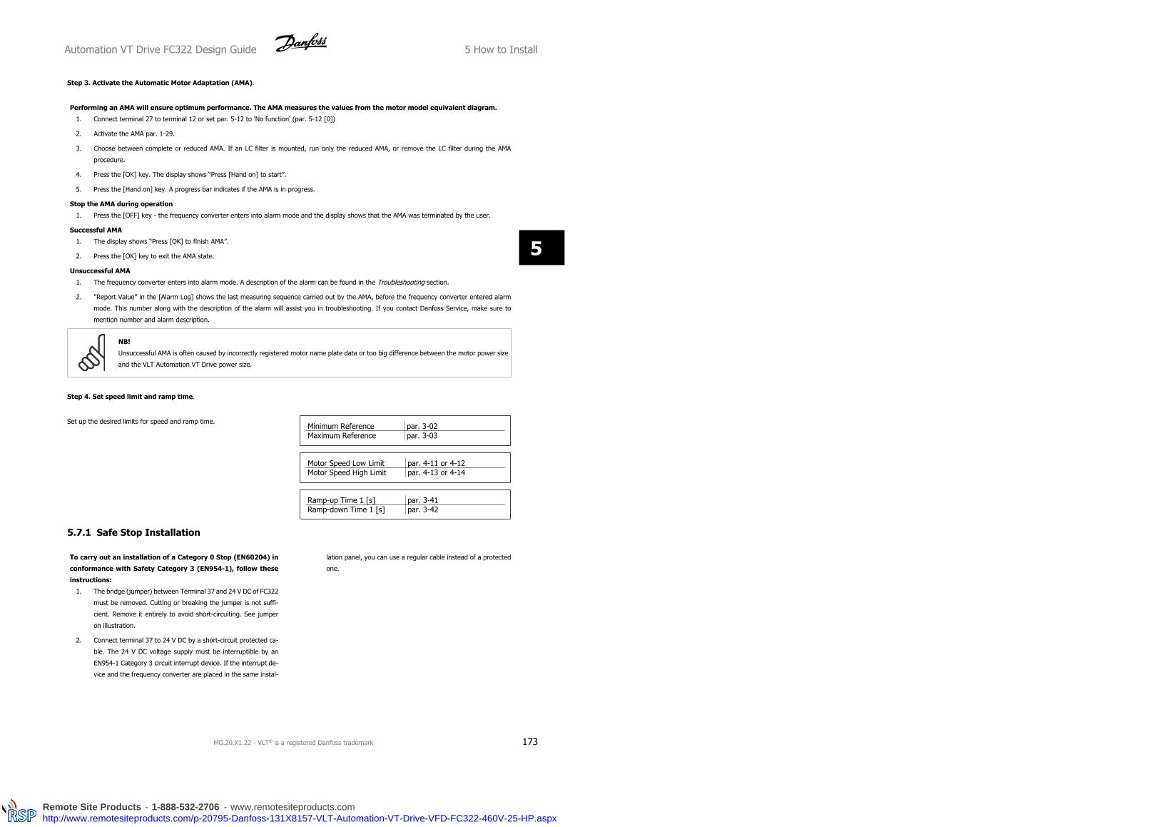
Step 3. Activate the Automatic Motor Adaptation (AMA).
Performing an AMA will ensure optimum performance. The AMA measures the values from the motor model equivalent diagram.
1. Connect terminal 27 to terminal 12 or set par. 5-12 to 'No function' (par. 5-12 [0])
2. Activate the AMA par. 1-29.
3. Choose between complete or reduced AMA. If an LC filter is mounted, run only the reduced AMA, or remove the LC filter during the AMA
procedure.
4. Press the [OK] key. The display shows “Press [Hand on] to start”.
5. Press the [Hand on] key. A progress bar indicates if the AMA is in progress.
Stop the AMA during operation
1. Press the [OFF] key - the frequency converter enters into alarm mode and the display shows that the AMA was terminated by the user.
Successful AMA
1. The display shows “Press [OK] to finish AMA”.
2. Press the [OK] key to exit the AMA state.
Unsuccessful AMA
1. The frequency converter enters into alarm mode. A description of the alarm can be found in the Troubleshooting section.
2. "Report Value” in the [Alarm Log] shows the last measuring sequence carried out by the AMA, before the frequency converter entered alarm
mode. This number along with the description of the alarm will assist you in troubleshooting. If you contact Danfoss Service, make sure to
mention number and alarm description.
NB!
Unsuccessful AMA is often caused by incorrectly registered motor name plate data or too big difference between the motor power size
and the VLT Automation VT Drive power size.
Step 4. Set speed limit and ramp time.
Set up the desired limits for speed and ramp time.Minimum Reference par. 3-02Maximum Reference par. 3-03
Motor Speed Low Limit par. 4-11 or 4-12Motor Speed High Limit par. 4-13 or 4-14
Ramp-up Time 1 [s] par. 3-41Ramp-down Time 1 [s] par. 3-42
5.7.1 Safe Stop Installation
To carry out an installation of a Category 0 Stop (EN60204) in
conformance with Safety Category 3 (EN954-1), follow these
instructions:
1. The bridge (jumper) between Terminal 37 and 24 V DC of FC322
must be removed. Cutting or breaking the jumper is not suffi-
cient. Remove it entirely to avoid short-circuiting. See jumper
on illustration.
2. Connect terminal 37 to 24 V DC by a short-circuit protected ca-
ble. The 24 V DC voltage supply must be interruptible by an
EN954-1 Category 3 circuit interrupt device. If the interrupt de-
vice and the frequency converter are placed in the same instal-
lation panel, you can use a regular cable instead of a protected
one.
Automation VT Drive FC322 Design Guide 5 How to Install
MG.20.X1.22 - VLT® is a registered Danfoss trademark 173
5
Remote Site Products - 1-888-532-2706 - www.remotesiteproducts.comhttp://www.remotesiteproducts.com/p-20795-Danfoss-131X8157-VLT-Automation-VT-Drive-VFD-FC322-460V-25-HP.aspx

Illustration 5.37: Bridge jumper between terminal 37 and 24
VDC.
The illustration below shows a Stopping Category 0 (EN 60204-1) with safety Cat. 3 (EN 954-1). The circuit interrupt is caused by an opening door contact.
The illustration also shows how to connect a non-safety related hardware coast.
Illustration 5.38: Illustration of the essential aspects of an installation to achieve a Stopping Category 0 (EN 60204-1) with safety Cat. 3 (EN
954-1).
5.7.2 Safe Stop Commissioning Test
After installation and before first operation, perform a commissioning test of an installation or application making use of FC 200 Safe Stop.
Moreover, perform the test after each modification of the installation or application, which the FC 200 Safe Stop is part of.
The commissioning test:
1. Remove the 24 V DC voltage supply to terminal 37 by the interrupt device while the motor is driven by the FC322 (i.e. mains supply is not
interrupted). The test step is passed if the motor reacts with a coast and the mechanical brake (if connected) is activated.
2. Then send Reset signal (via Bus, Digital I/O, or [Reset] key). The test step is passed if the motor remains in the Safe Stop state, and the
mechanical brake (if connected) remains activated.
5 How to Install Automation VT Drive FC322 Design Guide
174 MG.20.X1.22 - VLT® is a registered Danfoss trademark
5
Remote Site Products - 1-888-532-2706 - www.remotesiteproducts.comhttp://www.remotesiteproducts.com/p-20795-Danfoss-131X8157-VLT-Automation-VT-Drive-VFD-FC322-460V-25-HP.aspx

3. Then reapply 24 V DC to terminal 37. The test step is passed if the motor remains in the coasted state, and the mechanical brake (if connected)
remains activated.
4. Then send Reset signal (via Bus, Digital I/O, or [Reset] key). The test step is passed if the motor becomes operational again.
5. The commissioning test is passed if all four test steps are passed.
Automation VT Drive FC322 Design Guide 5 How to Install
MG.20.X1.22 - VLT® is a registered Danfoss trademark 175
5
Remote Site Products - 1-888-532-2706 - www.remotesiteproducts.comhttp://www.remotesiteproducts.com/p-20795-Danfoss-131X8157-VLT-Automation-VT-Drive-VFD-FC322-460V-25-HP.aspx

5.7 Additional Connections
5.8.1 Relay Output
Relay 1
• Terminal 01: common
• Terminal 02: normal open 240 V AC
• Terminal 03: normal closed 240 V AC
Relay 2
• Terminal 04: common
• Terminal 05: normal open 400 V AC
• Terminal 06: normal closed 240 V AC
Relay 1 and relay 2 are programmed in par. 5-40 Function Relay,
par. 5-41 On Delay, Relay, and par. 5-42 Off Delay, Relay.
Additional relay outputs by using option module MCB 105.
5 How to Install Automation VT Drive FC322 Design Guide
176 MG.20.X1.22 - VLT® is a registered Danfoss trademark
5
Remote Site Products - 1-888-532-2706 - www.remotesiteproducts.comhttp://www.remotesiteproducts.com/p-20795-Danfoss-131X8157-VLT-Automation-VT-Drive-VFD-FC322-460V-25-HP.aspx

5.8.2 Parallel Connection of Motors
The frequency converter can control several parallel-connected motors.
The total current consumption of the motors must not exceed the rated
output current IINV for the frequency converter.
NB!
When motors are connected in parallel, par. 1-29 Au-
tomatic Motor Adaptation (AMA) cannot be used.
Problems may arise at start and at low RPM values if motor sizes are
widely different because small motors' relatively high ohmic resistance in
the stator calls for a higher voltage at start and at low RPM values.
The electronic thermal relay (ETR) of the frequency converter cannot be
used as motor protection for the individual motor of systems with parallel-
connected motors. Provide further motor protection by e.g. thermistors
in each motor or individual thermal relays. (Circuit breakers are not suit-
able as protection).
Automation VT Drive FC322 Design Guide 5 How to Install
MG.20.X1.22 - VLT® is a registered Danfoss trademark 177
5
Remote Site Products - 1-888-532-2706 - www.remotesiteproducts.comhttp://www.remotesiteproducts.com/p-20795-Danfoss-131X8157-VLT-Automation-VT-Drive-VFD-FC322-460V-25-HP.aspx

5.8.3 Direction of Motor Rotation
The default setting is clockwise rotation with the frequency converter
output connected as follows.
Terminal 96 connected to U-phase
Terminal 97 connected to V-phase
Terminal 98 connected to W-phase
The direction of motor rotation is changed by switching two motor pha-
ses.
Motor rotation check can be performed using par. 1-28 Motor Rotation
Check and following the steps shown in the display.
5.8.4 Motor Thermal Protection
The electronic thermal relay in the frequency converter has received the UL-approval for single motor protection, when par. 1-90 Motor Thermal Protec-
tion is set for ETR Trip and par. 1-24 Motor Current is set to the rated motor current (see motor name plate).
5 How to Install Automation VT Drive FC322 Design Guide
178 MG.20.X1.22 - VLT® is a registered Danfoss trademark
5
Remote Site Products - 1-888-532-2706 - www.remotesiteproducts.comhttp://www.remotesiteproducts.com/p-20795-Danfoss-131X8157-VLT-Automation-VT-Drive-VFD-FC322-460V-25-HP.aspx

5.8 Installation of Misc. Connections
5.9.1 RS 485 Bus Connection
One or more frequency converters can be connected to a control (or
master) using the RS485 standardized interface. Terminal 68 is connec-
ted to the P signal (TX+, RX+), while terminal 69 is connected to the N
signal (TX-,RX-).
If more than one frequency converter is connected to a master, use par-
allel connections.
In order to avoid potential equalizing currents in the screen, earth the cable screen via terminal 61, which is connected to the frame via an RC-link.
Bus termination
The RS485 bus must be terminated by a resistor network at both ends. For this purpose, set switch S801 on the control card for "ON".
For more information, see the paragraph Switches S201, S202, and S801.
NB!
Communication protocol must be set to FC MC 8-30 Protocol.
5.9.2 How to Connect a PC to the VLT Automation VT Drive
To control or program the frequency converter from a PC, install the MCT 10 Set-up Software.
The PC is connected via a standard (host/device) USB cable, or via the RS-485 interface as shown in the VLT Automation VT Drive Design Guide
How to Install > Installation of misc. connections.
NB!
The USB connection is galvanically isolated from the supply voltage (PELV) and other high-voltage terminals. The USB connection is
connected to protection earth on the frequency converter. Use only isolated laptop as PC connection to the USB connector on the VLT
Automation VT Drive.
Automation VT Drive FC322 Design Guide 5 How to Install
MG.20.X1.22 - VLT® is a registered Danfoss trademark 179
5
Remote Site Products - 1-888-532-2706 - www.remotesiteproducts.comhttp://www.remotesiteproducts.com/p-20795-Danfoss-131X8157-VLT-Automation-VT-Drive-VFD-FC322-460V-25-HP.aspx

PC Software - MCT 10
All drives are equipped with a serial communication port. We provide a PC tool for communication between PC and frequency converter, VLT Motion
Control Tool MCT 10 Set-up Software.
MCT 10 Set-up Software
MCT 10 has been designed as an easy to use interactive tool for setting parameters in our frequency converters.
The MCT 10 Set-up Software will be useful for:
• Planning a communication network off-line. MCT 10 contains a complete frequency converter database
• Commissioning frequency converters on line
• Saving settings for all frequency converters
• Replacing a drive in a network
• Expanding an existing network
• Future developed drives will be supported
MCT 10
Set-up Software support Profibus DP-V1 via a Master class 2 connection. It makes it possible to on line read/write parameters in a frequency converter
via the Profibus network. This will eliminate the need for an extra communication network.
Save Drive Settings:
1. Connect a PC to the unit via USB com port
2. Open MCT 10 Set-up Software
3. Choose “Read from drive”
4. Choose “Save as”
All parameters are now stored in the PC.
Load Drive Settings:
1. Connect a PC to the unit via USB com port
2. Open MCT 10 Set-up software
5 How to Install Automation VT Drive FC322 Design Guide
180 MG.20.X1.22 - VLT® is a registered Danfoss trademark
5
Remote Site Products - 1-888-532-2706 - www.remotesiteproducts.comhttp://www.remotesiteproducts.com/p-20795-Danfoss-131X8157-VLT-Automation-VT-Drive-VFD-FC322-460V-25-HP.aspx

3. Choose “Open”– stored files will be shown
4. Open the appropriate file
5. Choose “Write to drive”
All parameter settings are now transferred to the drive.
A separate manual for MCT 10 Set-up Software is available.
The MCT 10 Set-up Software Modules
The following modules are included in the software package:
MCT 10 Set-up Software
Setting parameters
Copy to and from frequency converters
Documentation and print out of parameter settings incl. diagrams
Ext. User Interface
Preventive Maintenance Schedule
Clock settings
Timed Action Programming
Smart Logic Controller Set-up
Cascade Control Config. Tool
Ordering number:
Please order your CD containing MCT 10 Set-up Software using code number 130B1000.
MCT 10 can also be downloaded from the Danfoss Internet: WWW.DANFOSS.COM, Business Area: Motion Controls.
MCT 31
The MCT 31 harmonic calculation PC tool enables easy estimation of the harmonic distortion in a given application. Both the harmonic distortion of Danfoss
frequency converters as well as non-Danfoss frequency converters with different additional harmonic reduction devices, such as Danfoss AHF filters and
12-18-pulse rectifiers, can be calculated.
Ordering number:
Please order your CD containing the MCT 31 PC tool using code number 130B1031.
MCT 31 can also be downloaded from the Danfoss Internet: WWW.DANFOSS.COM, Business Area: Motion Controls.
5.9 Safety
5.10.1 High Voltage Test
Carry out a high voltage test by short-circuiting terminals U, V, W, L1, L2 and L3. Energize maximum 2.15 kV DC for 380-500V frequency converters and
2.525 kV DC for 525-690V frequency converters for one second between this short-circuit and the chassis.
NB!
When running high voltage tests of the entire installation, interrupt the mains and motor connection if the leakage currents are too
high.
5.10.2 Safety Earth Connection
The frequency converter has a high leakage current and must be earthed appropriately for safety reasons acording to EN 50178.
Automation VT Drive FC322 Design Guide 5 How to Install
MG.20.X1.22 - VLT® is a registered Danfoss trademark 181
5
Remote Site Products - 1-888-532-2706 - www.remotesiteproducts.comhttp://www.remotesiteproducts.com/p-20795-Danfoss-131X8157-VLT-Automation-VT-Drive-VFD-FC322-460V-25-HP.aspx

The earth leakage current from the frequency converter exceeds 3.5 mA. To ensure a good mechanical connection from the earth
cable to the earth connection (terminal 95), the cable cross-section must be at least 10 mm2 or 2 rated earth wires terminated sepa-
rately.
5.10 EMC-correct Installation
5.11.1 Electrical Installation - EMC Precautions
The following is a guideline to good engineering practice when installing frequency converters. Follow these guidelines to comply with EN 61800-3 First
environment. If the installation is in EN 61800-3 Second environment, i.e. industrial networks, or in an installation with its own transformer, deviation
from these guidelines is allowed but not recommended. See also paragraphs CE Labelling, General Aspects of EMC Emission and EMC Test Results.
Good engineering practice to ensure EMC-correct electrical installation:
• Use only braided screened/armoured motor cables and braided screened/armoured control cables. The screen should provide a minimum
coverage of 80%. The screen material must be metal, not limited to but typically copper, aluminium, steel or lead. There are no special re-
quirements for the mains cable.
• Installations using rigid metal conduits are not required to use screened cable, but the motor cable must be installed in conduit separate from
the control and mains cables. Full connection of the conduit from the drive to the motor is required. The EMC performance of flexible conduits
varies a lot and information from the manufacturer must be obtained.
• Connect the screen/armour/conduit to earth at both ends for motor cables as well as for control cables. In some cases, it is not possible to
connect the screen in both ends. If so, connect the screen at the frequency converter. See also Earthing of Braided Screened/Armoured Control
Cables.
• Avoid terminating the screen/armour with twisted ends (pigtails). It increases the high frequency impedance of the screen, which reduces its
effectiveness at high frequencies. Use low impedance cable clamps or EMC cable glands instead.
• Avoid using unscreened/unarmoured motor or control cables inside cabinets housing the drive(s), whenever this can be avoided.
Leave the screen as close to the connectors as possible.
The illustration shows an example of an EMC-correct electrical installation of an IP 20 frequency converter. The frequency converter is fitted in an
installation cabinet with an output contactor and connected to a PLC, which is installed in a separate cabinet. Other ways of doing the installation may
have just as good an EMC performance, provided the above guide lines to engineering practice are followed.
If the installation is not carried out according to the guideline and if unscreened cables and control wires are used, some emission requirements are not
complied with, although the immunity requirements are fulfilled. See the paragraph EMC test results.
5 How to Install Automation VT Drive FC322 Design Guide
182 MG.20.X1.22 - VLT® is a registered Danfoss trademark
5
Remote Site Products - 1-888-532-2706 - www.remotesiteproducts.comhttp://www.remotesiteproducts.com/p-20795-Danfoss-131X8157-VLT-Automation-VT-Drive-VFD-FC322-460V-25-HP.aspx

Illustration 5.39: EMC-correct electrical installation of a frequency converter in cabinet.
Automation VT Drive FC322 Design Guide 5 How to Install
MG.20.X1.22 - VLT® is a registered Danfoss trademark 183
5
Remote Site Products - 1-888-532-2706 - www.remotesiteproducts.comhttp://www.remotesiteproducts.com/p-20795-Danfoss-131X8157-VLT-Automation-VT-Drive-VFD-FC322-460V-25-HP.aspx

Illustration 5.40: Electrical connection diagram.
5 How to Install Automation VT Drive FC322 Design Guide
184 MG.20.X1.22 - VLT® is a registered Danfoss trademark
5
Remote Site Products - 1-888-532-2706 - www.remotesiteproducts.comhttp://www.remotesiteproducts.com/p-20795-Danfoss-131X8157-VLT-Automation-VT-Drive-VFD-FC322-460V-25-HP.aspx

5.11.2 Use of EMC-Correct Cables
Danfoss recommends braided screened/armoured cables to optimise EMC immunity of the control cables and the EMC emission from the motor cables.
The ability of a cable to reduce the in- and outgoing radiation of electric noise depends on the transfer impedance (ZT). The screen of a cable is normally
designed to reduce the transfer of electric noise; however, a screen with a lower transfer impedance (ZT) value is more effective than a screen with a
higher transfer impedance (ZT).
Transfer impedance (ZT) is rarely stated by cable manufacturers but it is often possible to estimate transfer impedance (ZT) by assessing the physical
design of the cable.
Transfer impedance (ZT) can be assessed on the basis of the following factors:
- The conductibility of the screen material.
- The contact resistance between the individual screen conductors.
- The screen coverage, i.e. the physical area of the cable covered by the screen - often stated as a percentage value.
- Screen type, i.e. braided or twisted pattern.
a. Aluminium-clad with copper wire.
b. Twisted copper wire or armoured steel wire cable.
c. Single-layer braided copper wire with varying percentage screen
coverage.
This is the typical Danfoss reference cable.
d. Double-layer braided copper wire.
e. Twin layer of braided copper wire with a magnetic, screened/
armoured intermediate layer.
f. Cable that runs in copper tube or steel tube.
g. Lead cable with 1.1 mm wall thickness.
Automation VT Drive FC322 Design Guide 5 How to Install
MG.20.X1.22 - VLT® is a registered Danfoss trademark 185
5
Remote Site Products - 1-888-532-2706 - www.remotesiteproducts.comhttp://www.remotesiteproducts.com/p-20795-Danfoss-131X8157-VLT-Automation-VT-Drive-VFD-FC322-460V-25-HP.aspx

5.11.3 Earthing of Screened/Armoured Control Cables
Generally speaking, control cables must be braided screened/armoured and the screen must be connected by means of a cable clamp at both ends to
the metal cabinet of the unit.
The drawing below indicates how correct earthing is carried out and what to do if in doubt.
a. Correct earthing
Control cables and cables for serial communication must be fit-
ted with cable clamps at both ends to ensure the best possible
electrical contact.
b. Wrong earthing
Do not use twisted cable ends (pigtails). They increase the
screen impedance at high frequencies.
c. Protection with respect to earth potential between PLC
and
If the earth potential between the frequency converter and the
PLC (etc.) is different, electric noise may occur that will disturb
the entire system. Solve this problem by fitting an equalising
cable, next to the control cable. Minimum cable cross-section:
16 mm 2.
d. For 50/60 Hz earth loops
If very long control cables are used, 50/60 Hz earth loops may
occur. Solve this problem by connecting one end of the screen
to earth via a 100nF capacitor (keeping leads short).
e. Cables for serial communication
Eliminate low-frequency noise currents between two frequency
converters by connecting one end of the screen to terminal 61.
This terminal is connected to earth via an internal RC link. Use
twisted-pair cables to reduce the differential mode interference
between the conductors.
5.12.1 Residual Current Device
You can use RCD relays, multiple protective earthing or earthing as extra protection, provided that local safety regulations are complied with.
If an earth fault appears, a DC content may develop in the faulty current.
If RCD relays are used, you must observe local regulations. Relays must be suitable for protection of 3-phase equipment with a bridge rectifier and for
a brief discharge on power-up see section Earth Leakage Current for further information.
5 How to Install Automation VT Drive FC322 Design Guide
186 MG.20.X1.22 - VLT® is a registered Danfoss trademark
5
Remote Site Products - 1-888-532-2706 - www.remotesiteproducts.comhttp://www.remotesiteproducts.com/p-20795-Danfoss-131X8157-VLT-Automation-VT-Drive-VFD-FC322-460V-25-HP.aspx

6 Application Examples
6.1.1 Start/Stop
Terminal 18 = start/stop par. 5-10 [8] Start
Terminal 27 = No operation par. 5-12 [0] No operation (Default coast
inverse
Par. 5-10 Digital Input, Terminal 18 = Start (default)
Par. 5-12 Digital Input, Terminal 27 = coast inverse (default)
Illustration 6.1: Terminal 37: Available only with Safe Stop
Function!
6.1.2 Pulse Start/Stop
Terminal 18 = start/stop par. 5-10 [9] Latched start
Terminal 27= Stop par. 5-12 [6] Stop inverse
Par. 5-10 Digital Input, Terminal 18 = Latched start
Par. 5-12 Digital Input, Terminal 27 = Stop inverse
Illustration 6.2: Terminal 37: Available only with Safe Stop
Function!
Automation VT Drive FC322 Design Guide 6 Application Examples
MG.20.X1.22 - VLT® is a registered Danfoss trademark 187
6
Remote Site Products - 1-888-532-2706 - www.remotesiteproducts.comhttp://www.remotesiteproducts.com/p-20795-Danfoss-131X8157-VLT-Automation-VT-Drive-VFD-FC322-460V-25-HP.aspx

6.1.3 Potentiometer Reference
Voltage reference via a potentiometer.
par. 3-15 Reference 1 Source [1] = Analog Input 53
par. 6-10 Terminal 53 Low Voltage = 0 Volt
par. 6-11 Terminal 53 High Voltage = 10 Volt
par. 6-14 Terminal 53 Low Ref./Feedb. Value = 0 RPM
par. 6-15 Terminal 53 High Ref./Feedb. Value = 1.500 RPM
Switch S201 = OFF (U)
6.1.4 Automatic Motor Adaptation (AMA)
AMA is an algorithm to measure the electrical motor parameters on a motor at standstill. This means thatAMA itself does not supply any torque.
AMA is useful when commissioning systems and optimising the adjustment of the frequency converter to the applied motor. This feature is particularly
used where the default setting does not apply to the connected motor.
par. 1-29 Automatic Motor Adaptation (AMA) allows a choice of complete AMA with determination of all electrical motor parameters or reduced AMA with
determination of the stator resistance Rs only.
The duration of a total AMA varies from a few minutes on small motors to more than 15 minutes on large motors.
Limitations and preconditions:
• For the AMA to determine the motor parameters optimally, enter the correct motor nameplate data in par. 1-20 Motor Power [kW] to
par. 1-28 Motor Rotation Check.
• For the best adjustment of the frequency converter, carry out AMA on a cold motor. Repeated AMA runs may lead to a heating of the motor,
which results in an increase of the stator resistance, Rs. Normally, this is not critical.
• AMA can only be carried out if the rated motor current is minimum 35% of the rated output current of the frequency converter. AMA can be
carried out on up to one oversize motor.
• It is possible to carry out a reduced AMA test with a Sine-wave filter installed. Avoid carrying out a complete AMA with a Sine-wave filter. If an
overall setting is required, remove the Sine-wave filter while running a total AMA. After completion of the AMA, reinsert the Sine-wave filter.
• If motors are coupled in parallel, use only reduced AMA if any.
• Avoid running a complete AMA when using synchronous motors. If synchronous motors are applied, run a reduced AMA and manually set the
extended motor data. The AMA function does not apply to permanent magnet motors.
• The frequency converter does not produce motor torque during an AMA. During an AMA, it is imperative that the application does not force the
motor shaft to run, which is known to happen with e.g. wind milling in ventilation systems. This disturbs the AMA function.
The Smart Logic Control (SLC) is essentially a sequence of user defined actions (see par. 13-52 SL Controller Action) executed by the SLC when the
associated user defined event (see par. 13-51 SL Controller Event) is evaluated as TRUE by the SLC.
Events and actions are each numbered and are linked in pairs called states. This means that when event [1] is fulfilled (attains the value TRUE), action
[1] is executed. After this, the conditions of event [2] will be evaluated and if evaluated TRUE, action [2]will be executed and so on. Events and actions
are placed in array parameters.
Only one event will be evaluated at any time. If an event is evaluated as FALSE, nothing happens (in the SLC) during the present scan interval and no
other events will be evaluated. This means that when the SLC starts, it evaluates event [1] (and only event [1]) each scan interval. Only when event
[1] is evaluated TRUE, the SLC executes action [1] and starts evaluating event [2].
6 Application Examples Automation VT Drive FC322 Design Guide
188 MG.20.X1.22 - VLT® is a registered Danfoss trademark
6
Remote Site Products - 1-888-532-2706 - www.remotesiteproducts.comhttp://www.remotesiteproducts.com/p-20795-Danfoss-131X8157-VLT-Automation-VT-Drive-VFD-FC322-460V-25-HP.aspx

It is possible to program from 0 to 20 events and actions. When the last
event / action has been executed, the sequence starts over again from
event [1] / action [1]. The illustration shows an example with three
events / actions:
6.1.5 Smart Logic Control Programming
New useful facility in VLT Automation VT Drive is the Smart Logic Control (SLC).
In applications where a PLC is generating a simple sequence the SLC may take over elementary tasks from the main control.
SLC is designed to act from event send to or generated in the VLT Automation VT Drive. The frequency converter will then perform the pre-programmed
action.
6.1.6 SLC Application Example
One sequence 1:
Start – ramp up – run at reference speed 2 sec – ramp down and hold shaft until stop.
Set the ramping times in par. 3-41 Ramp 1 Ramp Up Time and par. 3-42 Ramp 1 Ramp Down Time to the wanted times
tramp = tacc × nnorm (par. 1 − 25)
ref RPM
Set term 27 to No Operation (par. 5-12 Terminal 27 Digital Input)
Automation VT Drive FC322 Design Guide 6 Application Examples
MG.20.X1.22 - VLT® is a registered Danfoss trademark 189
6
Remote Site Products - 1-888-532-2706 - www.remotesiteproducts.comhttp://www.remotesiteproducts.com/p-20795-Danfoss-131X8157-VLT-Automation-VT-Drive-VFD-FC322-460V-25-HP.aspx

Set Preset reference 0 to first preset speed (par. 3-10 Preset Reference [0]) in percentage of Max reference speed (par. 3-03 Maximum Reference). Ex.:
60%
Set preset reference 1 to second preset speed (par. 3-10 Preset Reference [1] Ex.: 0 % (zero).
Set the timer 0 for constant running speed in par. 13-20 SL Controller Timer [0]. Ex.: 2 sec.
Set Event 1 in par. 13-51 SL Controller Event [1] to True [1]
Set Event 2 in par. 13-51 SL Controller Event [2] to On Reference [4]
Set Event 3 in par. 13-51 SL Controller Event [3] to Time Out 0 [30]
Set Event 4 in par. 13-51 SL Controller Event [1] to False [0]
Set Action 1 in par. 13-52 SL Controller Action [1] to Select preset 0 [10]
Set Action 2 in par. 13-52 SL Controller Action [2] to Start Timer 0 [29]
Set Action 3 in par. 13-52 SL Controller Action [3] to Select preset 1 [11]
Set Action 4 in par. 13-52 SL Controller Action [4] to No Action [1]
Set the Smart Logic Control in par. 13-00 SL Controller Mode to ON.
Start / stop command is applied on terminal 18. If stop signal is applied the frequency converter will ramp down and go into free mode.
6 Application Examples Automation VT Drive FC322 Design Guide
190 MG.20.X1.22 - VLT® is a registered Danfoss trademark
6
Remote Site Products - 1-888-532-2706 - www.remotesiteproducts.comhttp://www.remotesiteproducts.com/p-20795-Danfoss-131X8157-VLT-Automation-VT-Drive-VFD-FC322-460V-25-HP.aspx
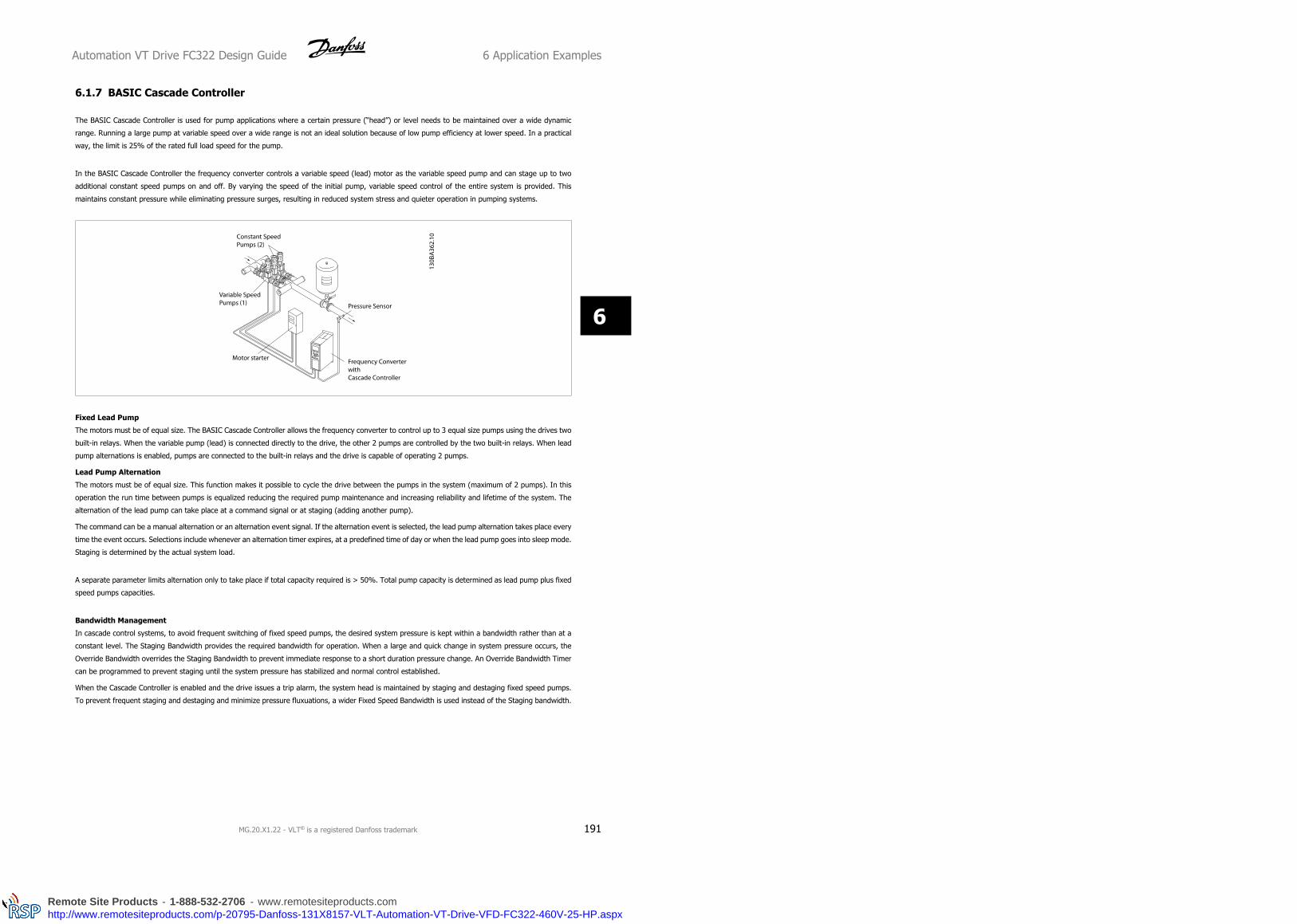
6.1.7 BASIC Cascade Controller
The BASIC Cascade Controller is used for pump applications where a certain pressure (“head”) or level needs to be maintained over a wide dynamic
range. Running a large pump at variable speed over a wide range is not an ideal solution because of low pump efficiency at lower speed. In a practical
way, the limit is 25% of the rated full load speed for the pump.
In the BASIC Cascade Controller the frequency converter controls a variable speed (lead) motor as the variable speed pump and can stage up to two
additional constant speed pumps on and off. By varying the speed of the initial pump, variable speed control of the entire system is provided. This
maintains constant pressure while eliminating pressure surges, resulting in reduced system stress and quieter operation in pumping systems.
Fixed Lead Pump
The motors must be of equal size. The BASIC Cascade Controller allows the frequency converter to control up to 3 equal size pumps using the drives two
built-in relays. When the variable pump (lead) is connected directly to the drive, the other 2 pumps are controlled by the two built-in relays. When lead
pump alternations is enabled, pumps are connected to the built-in relays and the drive is capable of operating 2 pumps.
Lead Pump Alternation
The motors must be of equal size. This function makes it possible to cycle the drive between the pumps in the system (maximum of 2 pumps). In this
operation the run time between pumps is equalized reducing the required pump maintenance and increasing reliability and lifetime of the system. The
alternation of the lead pump can take place at a command signal or at staging (adding another pump).
The command can be a manual alternation or an alternation event signal. If the alternation event is selected, the lead pump alternation takes place every
time the event occurs. Selections include whenever an alternation timer expires, at a predefined time of day or when the lead pump goes into sleep mode.
Staging is determined by the actual system load.
A separate parameter limits alternation only to take place if total capacity required is > 50%. Total pump capacity is determined as lead pump plus fixed
speed pumps capacities.
Bandwidth Management
In cascade control systems, to avoid frequent switching of fixed speed pumps, the desired system pressure is kept within a bandwidth rather than at a
constant level. The Staging Bandwidth provides the required bandwidth for operation. When a large and quick change in system pressure occurs, the
Override Bandwidth overrides the Staging Bandwidth to prevent immediate response to a short duration pressure change. An Override Bandwidth Timer
can be programmed to prevent staging until the system pressure has stabilized and normal control established.
When the Cascade Controller is enabled and the drive issues a trip alarm, the system head is maintained by staging and destaging fixed speed pumps.
To prevent frequent staging and destaging and minimize pressure fluxuations, a wider Fixed Speed Bandwidth is used instead of the Staging bandwidth.
Automation VT Drive FC322 Design Guide 6 Application Examples
MG.20.X1.22 - VLT® is a registered Danfoss trademark 191
6
Remote Site Products - 1-888-532-2706 - www.remotesiteproducts.comhttp://www.remotesiteproducts.com/p-20795-Danfoss-131X8157-VLT-Automation-VT-Drive-VFD-FC322-460V-25-HP.aspx

6.1.8 Pump Staging with Lead Pump Alternation
With lead pump alternation enabled, a maximum of two pumps are con-
trolled. At an alternation command, the PID stops, the lead pump ramps
to minimum frequency (fmin) and after a delay, it ramps to maximum fre-
quency (fmax). When the speed of the lead pump reaches the de-staging
frequency, the fixed speed pump will be cut out (de-staged). The lead
pump continues to ramp up and then ramps down to a stop and the two
relays are cut out.
After a time delay, the relay for the fixed speed pump cuts in (staged) and this pump becomes the new lead pump. The new lead pump ramps up to
maximum speed and then down to minimum speed. When ramping down and reaching the staging frequency, the old lead pump is now cut in (staged)
on the mains as the new fixed speed pump.
If the lead pump has been running at minimum frequency (fmin) for a programmed amount of time, with a fixed speed pump running, the lead pump
contributes little to the system. When programmed value of the timer expires, the lead pump is removed avoiding water heating problems.
6.1.9 System Status and Operation
If the lead pump goes into Sleep Mode, the function is displayed on the Local Control Panel. It is possible to alternate the lead pump on a Sleep Mode
condition.
When the cascade controller is enabled, the operation status for each pump and the cascade controller is displayed on the Local Control Panel. Information
displayed includes:
• Pumps Status, is a read out of the status for the relays assigned to each pump. The display shows pumps that are disabled, off, running on the
frequency converter or running on the mains/motor starter.
• Cascade Status, is a read out of the status for the Cascade Controller. The display shows the Cascade Controller is disabled, all pumps are off,
and emergency has stopped all pumps, all pumps are running, fixed speed pumps are being staged/destaged and lead pump alternation is
occurring.
• Destage at No-Flow ensures that all fixed speed pumps are stopped individually until the no-flow status disappears.
6 Application Examples Automation VT Drive FC322 Design Guide
192 MG.20.X1.22 - VLT® is a registered Danfoss trademark
6
Remote Site Products - 1-888-532-2706 - www.remotesiteproducts.comhttp://www.remotesiteproducts.com/p-20795-Danfoss-131X8157-VLT-Automation-VT-Drive-VFD-FC322-460V-25-HP.aspx

6.1.10 Cascade Controller Wiring Diagram
The wiring diagram shows an example with the built in BASIC cascade controller with one variable speed pump (lead) and two fixed speed pumps, a
4-20 mA transmitter and System Safety Interlock.
Automation VT Drive FC322 Design Guide 6 Application Examples
MG.20.X1.22 - VLT® is a registered Danfoss trademark 193
6
Remote Site Products - 1-888-532-2706 - www.remotesiteproducts.comhttp://www.remotesiteproducts.com/p-20795-Danfoss-131X8157-VLT-Automation-VT-Drive-VFD-FC322-460V-25-HP.aspx
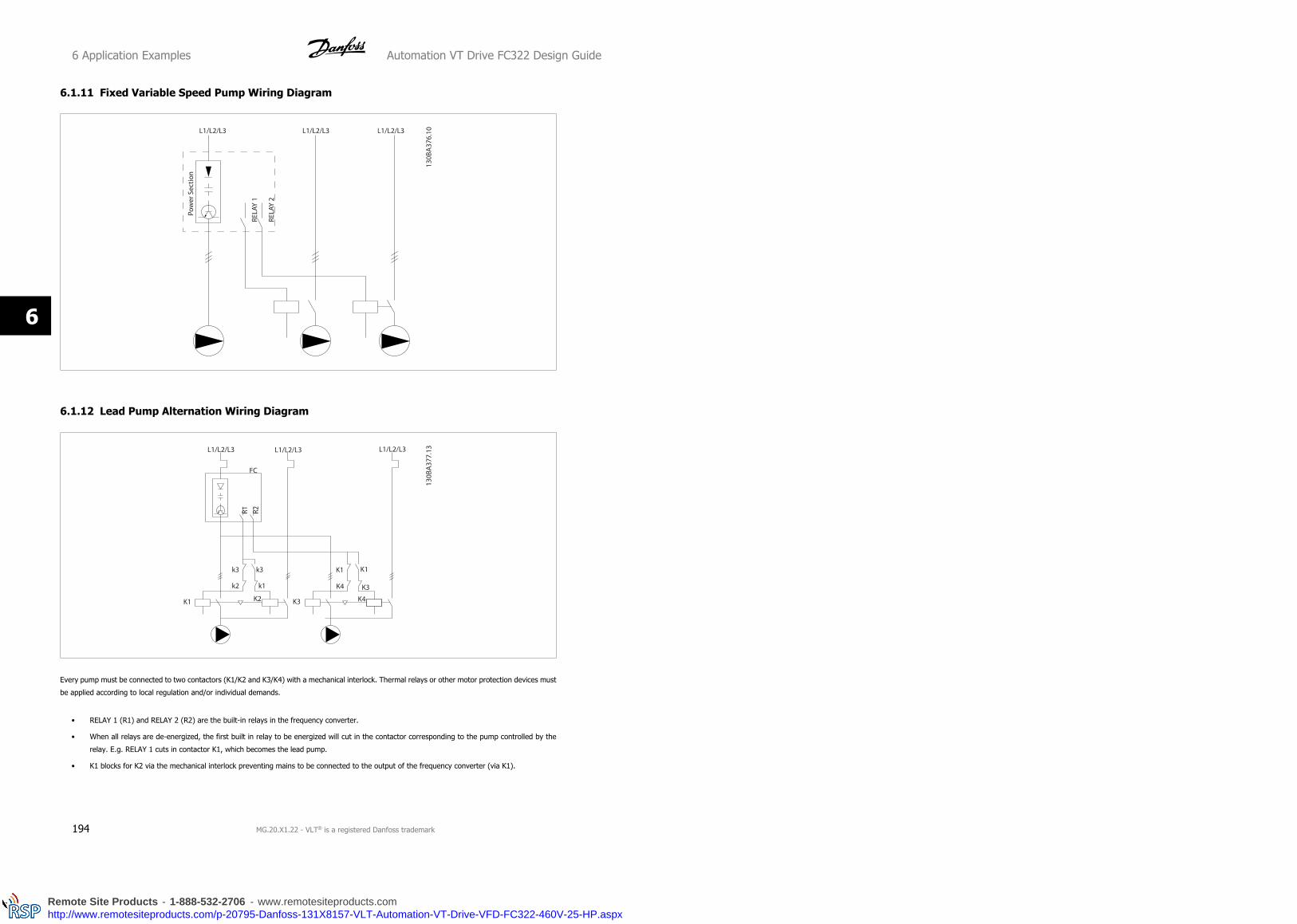
6.1.11 Fixed Variable Speed Pump Wiring Diagram
6.1.12 Lead Pump Alternation Wiring Diagram
Every pump must be connected to two contactors (K1/K2 and K3/K4) with a mechanical interlock. Thermal relays or other motor protection devices must
be applied according to local regulation and/or individual demands.
• RELAY 1 (R1) and RELAY 2 (R2) are the built-in relays in the frequency converter.
• When all relays are de-energized, the first built in relay to be energized will cut in the contactor corresponding to the pump controlled by the
relay. E.g. RELAY 1 cuts in contactor K1, which becomes the lead pump.
• K1 blocks for K2 via the mechanical interlock preventing mains to be connected to the output of the frequency converter (via K1).
6 Application Examples Automation VT Drive FC322 Design Guide
194 MG.20.X1.22 - VLT® is a registered Danfoss trademark
6
Remote Site Products - 1-888-532-2706 - www.remotesiteproducts.comhttp://www.remotesiteproducts.com/p-20795-Danfoss-131X8157-VLT-Automation-VT-Drive-VFD-FC322-460V-25-HP.aspx

• Auxiliary break contact on K1 prevents K3 to cut in.
• RELAY 2 controls contactor K4 for on/off control of the fixed speed pump.
• At alternation both relays de-energizes and now RELAY 2 will be energized as the first relay.
6.1.13 Start/Stop Conditions
Commands assigned to digital inputs. See Digital Inputs, par.5-1*.
Variable speed pump (lead) Fixed speed pumps
Start (SYSTEM START /STOP) Ramps up (if stopped and there is a demand) Staging (if stopped and there is a demand)
Lead Pump Start Ramps up if SYSTEM START is active Not affected
Coast (EMERGENCY STOP) Coast to stop Cut out (built in relays are de-energized)
Safety Interlock Coast to stop Cut out (built in relays are de-energized)
Function of buttons on Local Control Panel
Variable speed pump (lead) Fixed speed pumps
Hand On Ramps up (if stopped by a normal stop com-
mand) or stays in operation if already running
Destaging (if running)
Off Ramps down Cut out
Auto On Starts and stops according to commands via ter-
minals or serial bus
Staging/Destaging
Automation VT Drive FC322 Design Guide 6 Application Examples
MG.20.X1.22 - VLT® is a registered Danfoss trademark 195
6
Remote Site Products - 1-888-532-2706 - www.remotesiteproducts.comhttp://www.remotesiteproducts.com/p-20795-Danfoss-131X8157-VLT-Automation-VT-Drive-VFD-FC322-460V-25-HP.aspx

7 RS-485 Installation and Set-up Automation VT Drive FC322 Design Guide
196 MG.20.X1.22 - VLT® is a registered Danfoss trademark
7
Remote Site Products - 1-888-532-2706 - www.remotesiteproducts.comhttp://www.remotesiteproducts.com/p-20795-Danfoss-131X8157-VLT-Automation-VT-Drive-VFD-FC322-460V-25-HP.aspx

7 RS-485 Installation and Set-up
7.1 RS-485 Installation and Set-up
7.1.1 Overview
RS-485 is a two-wire bus interface compatible with multi-drop network topology, i.e. nodes can be connected as a bus, or via drop cables from a common
trunk line. A total of 32 nodes can be connected to one network segment.
Network segments are divided up by repeaters. Please note that each repeater functions as a node within the segment in which it is installed. Each node
connected within a given network must have a unique node address, across all segments.
Terminate each segment at both ends, using either the termination switch (S801) of the frequency converters or a biased termination resistor network.
Always use screened twisted pair (STP) cable for bus cabling, and always follow good common installation practice.
Low-impedance ground connection of the screen at every node is very important, including at high frequencies. This can be achieved by connecting a
large surface of the screen to ground, for example by means of a cable clamp or a conductive cable gland. It may be necessary to apply potential-
equalizing cables to maintain the same ground potential throughout the network, particularly in installations where there are long lengths of cable.
To prevent impedance mismatch, always use the same type of cable throughout the entire network. When connecting a motor to the frequency converter,
always use screened motor cable.
Cable: Screened twisted pair (STP)
Impedance: 120 Ohm
Cable length: Max. 1200 m (including drop lines)
Max. 500 m station-to-station
7.1.2 Network Connection
Connect the frequency converter to the RS-485 network as follows (see also diagram):
1. Connect signal wires to terminal 68 (P+) and terminal 69 (N-) on the main control board of the frequency converter.
2. Connect the cable screen to the cable clamps.
NB!
Screened, twisted-pair cables are recommended in or-
der to reduce noise between conductors.
Illustration 7.1: Network Terminal Connection
Automation VT Drive FC322 Design Guide 7 RS-485 Installation and Set-up
MG.20.X1.22 - VLT® is a registered Danfoss trademark 197
7
Remote Site Products - 1-888-532-2706 - www.remotesiteproducts.comhttp://www.remotesiteproducts.com/p-20795-Danfoss-131X8157-VLT-Automation-VT-Drive-VFD-FC322-460V-25-HP.aspx

Illustration 7.2: Control card terminals
7.1.3 VLT Automation VT Drive Hardware Setup
Use the terminator dip switch on the main control board of the frequency
converter to terminate the RS-485 bus.
Terminator Switch Factory Setting
NB!
The factory setting for the dip switch is OFF.
7.1.4 VLT Automation VT Drive Parameter Settings for Modbus Communication
The following parameters apply to the RS-485 interface (FC-port):
7 RS-485 Installation and Set-up Automation VT Drive FC322 Design Guide
198 MG.20.X1.22 - VLT® is a registered Danfoss trademark
7
Remote Site Products - 1-888-532-2706 - www.remotesiteproducts.comhttp://www.remotesiteproducts.com/p-20795-Danfoss-131X8157-VLT-Automation-VT-Drive-VFD-FC322-460V-25-HP.aspx

Parameter Number Parameter name Function
8-30 Protocol Select the application protocol to run on the RS-485 interface
8-31 Address Set the node address. Note: The address range depends on the protocol se-
lected in par. 8-30
8-32 Baud Rate Set the baud rate. Note: The default baud rate depends on the protocol se-
lected in par. 8-30
8-33 PC port parity/Stop bits Set the parity and number of stop bits. Note: The default selection depends
on the protocol selected in par. 8-30
8-35 Min. response delay Specify a minimum delay time between receiving a request and transmitting
a response. This can be used for overcoming modem turnaround delays.
8-36 Max. response delay Specify a maximum delay time between transmitting a request and receiving
a response.
8-37 Max. inter-char delay Specify a maximum delay time between two received bytes to ensure timeout
if transmission is interrupted.
7.1.5 EMC Precautions
The following EMC precautions are recommended in order to achieve interference-free operation of the RS-485 network.
NB!
Relevant national and local regulations, for example regarding protective earth connection, must be observed. The RS-485 communi-
cation cable must be kept away from motor and brake resistor cables to avoid coupling of high frequency noise from one cable to
another. Normally a distance of 200 mm (8 inches) is sufficient, but keeping the greatest possible distance between the cables is
generally recommended, especially where cables run in parallel over long distances. When crossing is unavoidable, the RS-485 cable
must cross motor and brake resistor cables at an angle of 90 degrees.
7.2 FC Protocol Overview
Automation VT Drive FC322 Design Guide 7 RS-485 Installation and Set-up
MG.20.X1.22 - VLT® is a registered Danfoss trademark 199
7
Remote Site Products - 1-888-532-2706 - www.remotesiteproducts.comhttp://www.remotesiteproducts.com/p-20795-Danfoss-131X8157-VLT-Automation-VT-Drive-VFD-FC322-460V-25-HP.aspx

The FC protocol, also referred to as FC bus or Standard bus, is the Danfoss standard fieldbus. It defines an access technique according to the master-
slave principle for communications via a serial bus.
One master and a maximum of 126 slaves can be connected to the bus. The individual slaves are selected by the master via an address character in the
telegram. A slave itself can never transmit without first being requested to do so, and direct message transfer between the individual slaves is not possible.
Communications occur in the half-duplex mode.
The master function cannot be transferred to another node (single-master system).
The physical layer is RS-485, thus utilizing the RS-485 port built into the frequency converter. The FC protocol supports different telegram formats; a
short format of 8 bytes for process data, and a long format of 16 bytes that also includes a parameter channel. A third telegram format is used for texts.
7.2.1 VLT Automation VT Drive with Modbus RTU
The FC protocol provides access to the Control Word and Bus Reference of the frequency converter.
The Control Word allows the Modbus master to control several important functions of the frequency converter:
• Start
• Stop of the frequency converter in various ways:
Coast stop
Quick stop
DC Brake stop
Normal (ramp) stop
• Reset after a fault trip
• Run at a variety of preset speeds
• Run in reverse
• Change of the active set-up
• Control of the two relays built into the frequency converter
The Bus Reference is commonly used for speed control. It is also possible to access the parameters, read their values, and where possible, write values
to them. This permits a range of control options, including controlling the setpoint of the frequency converter when its internal PID controller is used.
7 RS-485 Installation and Set-up Automation VT Drive FC322 Design Guide
200 MG.20.X1.22 - VLT® is a registered Danfoss trademark
7
Remote Site Products - 1-888-532-2706 - www.remotesiteproducts.comhttp://www.remotesiteproducts.com/p-20795-Danfoss-131X8157-VLT-Automation-VT-Drive-VFD-FC322-460V-25-HP.aspx

7.3 Network Configuration
7.3.1 VLT Automation VT Drive Frequency Converter Set-up
Set the following parameters to enable the FC protocol for the VLT Au-
tomation VT Drive.
Parameter Number Parameter name Setting
8-30 Protocol FC
8-31 Address 1 - 126
8-32 Baud Rate 2400 - 115200
8-33 Parity/Stop bits Even parity, 1 stop bit (default)
7.4 FC Protocol Message Framing Structure
7.4.1 Content of a Character (byte)
Each character transferred begins with a start bit. Then 8 data bits are transferred, corresponding to a byte. Each character is secured via a parity bit,
which is set at "1" when it reaches parity (i.e. when there is an equal number of 1’s in the 8 data bits and the parity bit in total). A character is completed
by a stop bit, thus consisting of 11 bits in all.
7.4.2 Telegram Structure
Each telegram begins with a start character (STX)=02 Hex, followed by a byte denoting the telegram length (LGE) and a byte denoting the frequency
converter address (ADR). A number of data bytes (variable, depending on the type of telegram) follows. The telegram is completed by a data control
byte (BCC).
7.4.3 Telegram Length (LGE)
The telegram length is the number of data bytes plus the address byte ADR and the data control byte BCC.
The length of telegrams with 4 data bytes is LGE = 4 + 1 + 1 = 6 bytes
The length of telegrams with 12 data bytes is LGE = 12 + 1 + 1 = 14 bytes
The length of telegrams containing texts is 101)+n bytes
Automation VT Drive FC322 Design Guide 7 RS-485 Installation and Set-up
MG.20.X1.22 - VLT® is a registered Danfoss trademark 201
7
Remote Site Products - 1-888-532-2706 - www.remotesiteproducts.comhttp://www.remotesiteproducts.com/p-20795-Danfoss-131X8157-VLT-Automation-VT-Drive-VFD-FC322-460V-25-HP.aspx

1) The 10 represents the fixed characters, while the “n’” is variable (depending on the length of the text).
7.4.4 Frequency Converter Address (ADR)
Two different address formats are used.
The address range of the frequency converter is either 1-31 or 1-126.
1. Address format 1-31:
Bit 7 = 0 (address format 1-31 active)
Bit 6 is not used
Bit 5 = 1: Broadcast, address bits (0-4) are not used
Bit 5 = 0: No Broadcast
Bit 0-4 = Frequency converter address 1-31
2. Address format 1-126:
Bit 7 = 1 (address format 1-126 active)
Bit 0-6 = Frequency converter address 1-126
Bit 0-6 = 0 Broadcast
The slave returns the address byte unchanged to the master in the response telegram.
7.4.5 Data Control Byte (BCC)
The checksum is calculated as an XOR-function. Before the first byte in the telegram is received, the Calculated Checksum is 0.
7.4.6 The Data Field
The structure of data blocks depends on the type of telegram. There are three telegram types, and the type applies for both control telegrams (mas-
ter=>slave) and response telegrams (slave=>master).
The three types of telegram are:
Process block (PCD):
The PCD is made up of a data block of four bytes (2 words) and contains:
- Control word and reference value (from master to slave)
- Status word and present output frequency (from slave to master).
Parameter block:
The parameter block is used to transfer parameters between master and slave. The data block is made up of 12 bytes (6 words) and also contains the
process block.
7 RS-485 Installation and Set-up Automation VT Drive FC322 Design Guide
202 MG.20.X1.22 - VLT® is a registered Danfoss trademark
7
Remote Site Products - 1-888-532-2706 - www.remotesiteproducts.comhttp://www.remotesiteproducts.com/p-20795-Danfoss-131X8157-VLT-Automation-VT-Drive-VFD-FC322-460V-25-HP.aspx
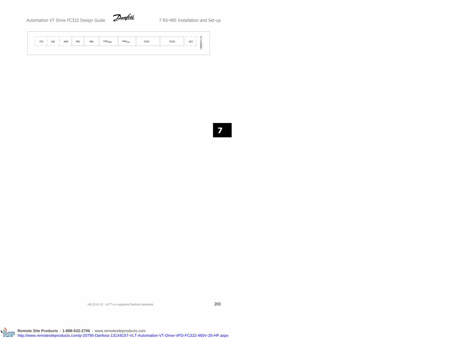
Automation VT Drive FC322 Design Guide 7 RS-485 Installation and Set-up
MG.20.X1.22 - VLT® is a registered Danfoss trademark 203
7
Remote Site Products - 1-888-532-2706 - www.remotesiteproducts.comhttp://www.remotesiteproducts.com/p-20795-Danfoss-131X8157-VLT-Automation-VT-Drive-VFD-FC322-460V-25-HP.aspx

Text block:
The text block is used to read or write texts via the data block.
7.4.7 The PKE Field
The PKE field contains two sub-fields: Parameter command and response AK, and Parameter number PNU:
Bits no. 12-15 transfer parameter commands from master to slave and return processed slave responses to the master.
Parameter commands master ⇒ slave
Bit no. Parameter command
15 14 13 12
0 0 0 0 No command
0 0 0 1 Read parameter value
0 0 1 0 Write parameter value in RAM (word)
0 0 1 1 Write parameter value in RAM (double word)
1 1 0 1 Write parameter value in RAM and EEprom (double word)
1 1 1 0 Write parameter value in RAM and EEprom (word)
1 1 1 1 Read/write text
7 RS-485 Installation and Set-up Automation VT Drive FC322 Design Guide
204 MG.20.X1.22 - VLT® is a registered Danfoss trademark
7
Remote Site Products - 1-888-532-2706 - www.remotesiteproducts.comhttp://www.remotesiteproducts.com/p-20795-Danfoss-131X8157-VLT-Automation-VT-Drive-VFD-FC322-460V-25-HP.aspx

Response slave ⇒master
Bit no. Response
15 14 13 12
0 0 0 0 No response
0 0 0 1 Parameter value transferred (word)
0 0 1 0 Parameter value transferred (double word)
0 1 1 1 Command cannot be performed
1 1 1 1 text transferred
Automation VT Drive FC322 Design Guide 7 RS-485 Installation and Set-up
MG.20.X1.22 - VLT® is a registered Danfoss trademark 205
7
Remote Site Products - 1-888-532-2706 - www.remotesiteproducts.comhttp://www.remotesiteproducts.com/p-20795-Danfoss-131X8157-VLT-Automation-VT-Drive-VFD-FC322-460V-25-HP.aspx

If the command cannot be performed, the slave sends this response:
0111 Command cannot be performed
- and issues the following fault report in the parameter value (PWE):
PWE low (Hex) Fault Report
0 The parameter number used does not exit
1 There is no write access to the defined parameter
2 Data value exceeds the parameter's limits
3 The sub index used does not exit
4 The parameter is not the array type
5 The data type does not match the defined parameter
11 Data change in the defined parameter is not possible in the frequency converter's present mode. Certain parameters
can only be changed when the motor is turned off
82 There is no bus access to the defined parameter
83 Data change is not possible because factory setup is selected
7.4.8 Parameter Number (PNU)
Bits no. 0-11 transfer parameter numbers. The function of the relevant parameter is defined in the parameter description in the chapter How to Pro-
gramme.
7.4.9 Index (IND)
The index is used together with the parameter number to read/write-access parameters with an index, e.g. par. 15-30 Alarm Log: Error Code. The index
consists of 2 bytes, a low byte and a high byte.
NB!
Only the low byte is used as an index.
7.4.10 Parameter Value (PWE)
The parameter value block consists of 2 words (4 bytes), and the value depends on the defined command (AK). The master prompts for a parameter
value when the PWE block contains no value. To change a parameter value (write), write the new value in the PWE block and send from the master to
the slave.
When a slave responds to a parameter request (read command), the present parameter value in the PWE block is transferred and returned to the master.
If a parameter contains not a numerical value but several data options, e.g. par. 0-01 Language where [0] corresponds to English, and [4] corresponds
to Danish, select the data value by entering the value in the PWE block. See Example - Selecting a data value. Serial communication is only capable of
reading parameters containing data type 9 (text string).
par. 15-40 FC Type to par. 15-53 Power Card Serial Number contain data type 9.
For example, read the unit size and mains voltage range in par. 15-40 FC Type. When a text string is transferred (read), the length of the telegram is
variable, and the texts are of different lengths. The telegram length is defined in the second byte of the telegram, LGE. When using text transfer the
index character indicates whether it is a read or a write command.
7 RS-485 Installation and Set-up Automation VT Drive FC322 Design Guide
206 MG.20.X1.22 - VLT® is a registered Danfoss trademark
7
Remote Site Products - 1-888-532-2706 - www.remotesiteproducts.comhttp://www.remotesiteproducts.com/p-20795-Danfoss-131X8157-VLT-Automation-VT-Drive-VFD-FC322-460V-25-HP.aspx

To read a text via the PWE block, set the parameter command (AK) to ’F’ Hex. The index character high-byte must be “4”.
Some parameters contain text that can be written to via the serial bus. To write a text via the PWE block, set the parameter command (AK) to ’F’ Hex.
The index characters high-byte must be “5”.
7.4.11 Data Types Supported by VLT Automation VT Drive
Data types Description
3 Integer 16
4 Integer 32
5 Unsigned 8
6 Unsigned 16
7 Unsigned 32
9 Text string
10 Byte string
13 Time difference
33 Reserved
35 Bit sequence
Unsigned means that there is no operational sign in the telegram.
7.4.12 Conversion
The various attributes of each parameter are displayed in the section
Factory Settings. Parameter values are transferred as whole numbers
only. Conversion factors are therefore used to transfer decimals.
par. 4-12 Motor Speed Low Limit [Hz] has a conversion factor of 0.1.
To preset the minimum frequency to 10 Hz, transfer the value 100. A
conversion factor of 0.1 means that the value transferred is multiplied by
0.1. The value 100 is thus perceived as 10.0.
Conversion table
Conversion index Conversion factor
74 0.1
2 100
1 10
0 1
-1 0.1
-2 0.01
-3 0.001
-4 0.0001
-5 0.00001
7.4.13 Process Words (PCD)
The block of process words is divided into two blocks of 16 bits, which always occur in the defined sequence.
Automation VT Drive FC322 Design Guide 7 RS-485 Installation and Set-up
MG.20.X1.22 - VLT® is a registered Danfoss trademark 207
7
Remote Site Products - 1-888-532-2706 - www.remotesiteproducts.comhttp://www.remotesiteproducts.com/p-20795-Danfoss-131X8157-VLT-Automation-VT-Drive-VFD-FC322-460V-25-HP.aspx

PCD 1 PCD 2
Control telegram (master⇒slave Control word) Reference-value
Control telegram (slave ⇒master) Status word Present outp. frequency
7 RS-485 Installation and Set-up Automation VT Drive FC322 Design Guide
208 MG.20.X1.22 - VLT® is a registered Danfoss trademark
7
Remote Site Products - 1-888-532-2706 - www.remotesiteproducts.comhttp://www.remotesiteproducts.com/p-20795-Danfoss-131X8157-VLT-Automation-VT-Drive-VFD-FC322-460V-25-HP.aspx
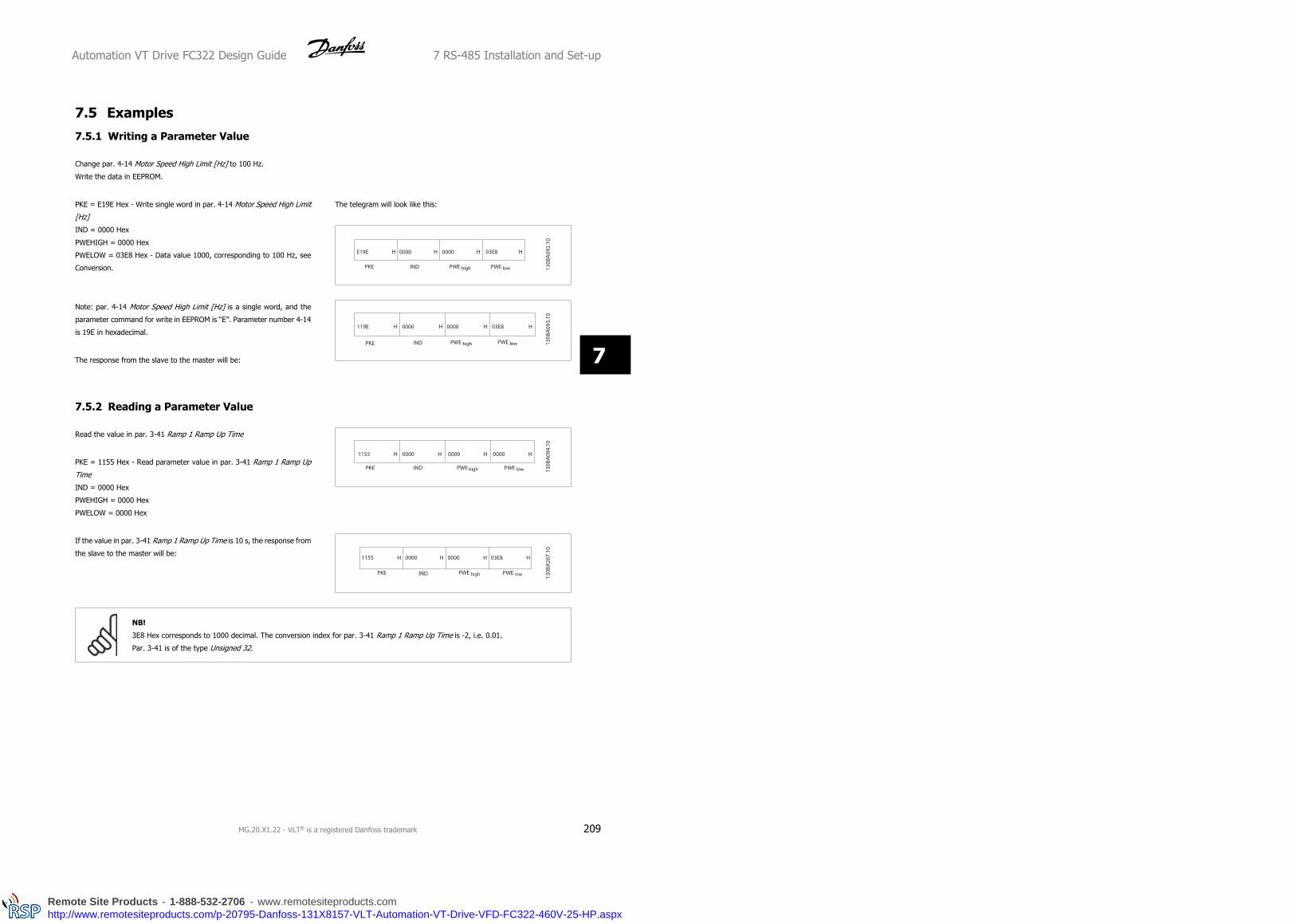
7.5 Examples
7.5.1 Writing a Parameter Value
Change par. 4-14 Motor Speed High Limit [Hz] to 100 Hz.
Write the data in EEPROM.
PKE = E19E Hex - Write single word in par. 4-14 Motor Speed High Limit
[Hz]
IND = 0000 Hex
PWEHIGH = 0000 Hex
PWELOW = 03E8 Hex - Data value 1000, corresponding to 100 Hz, see
Conversion.
The telegram will look like this:
Note: par. 4-14 Motor Speed High Limit [Hz] is a single word, and the
parameter command for write in EEPROM is “E”. Parameter number 4-14
is 19E in hexadecimal.
The response from the slave to the master will be:
7.5.2 Reading a Parameter Value
Read the value in par. 3-41 Ramp 1 Ramp Up Time
PKE = 1155 Hex - Read parameter value in par. 3-41 Ramp 1 Ramp Up
Time
IND = 0000 Hex
PWEHIGH = 0000 Hex
PWELOW = 0000 Hex
If the value in par. 3-41 Ramp 1 Ramp Up Time is 10 s, the response from
the slave to the master will be:
NB!
3E8 Hex corresponds to 1000 decimal. The conversion index for par. 3-41 Ramp 1 Ramp Up Time is -2, i.e. 0.01.
Par. 3-41 is of the type Unsigned 32.
Automation VT Drive FC322 Design Guide 7 RS-485 Installation and Set-up
MG.20.X1.22 - VLT® is a registered Danfoss trademark 209
7
Remote Site Products - 1-888-532-2706 - www.remotesiteproducts.comhttp://www.remotesiteproducts.com/p-20795-Danfoss-131X8157-VLT-Automation-VT-Drive-VFD-FC322-460V-25-HP.aspx

7.6 Modbus RTU Overview
7.6.1 Assumptions
This instruction manual assumes that the installed controller supports the interfaces in this document and that all the requirements stipulated in the
controller, as well as the frequency converter, are strictly observed, along with all limitations therein.
7.6.2 What the User Should Already Know
The Modbus RTU (Remote Terminal Unit) is designed to communicate with any controller that supports the interfaces defined in this document. It is
assumed that the user has full knowledge of the capabilities and limitations of the controller.
7.6.3 Modbus RTU Overview
Regardless of the type of physical communication networks, the Modbus RTU Overview describes the process a controller uses to request access to
another device. This includes i.a. how it will respond to requests from another device, and how errors will be detected and reported. It also establishes
a common format for the layout and contents of message fields.
During communications over a Modbus RTU network, the protocol determines how each controller will learn its device address, recognise a message
addressed to it, determine the kind of action to be taken, and extract any data or other information contained in the message. If a reply is required, the
controller will construct the reply message and send it.
Controllers communicate using a master-slave technique in which only one device (the master) can initiate transactions (called queries). The other devices
(slaves) respond by supplying the requested data to the master, or by taking the action requested in the query.
The master can address individual slaves, or can initiate a broadcast message to all slaves. Slaves return a message (called a response) to queries that
are addressed to them individually. No responses are returned to broadcast queries from the master. The Modbus RTU protocol establishes the format
for the master’s query by placing into it the device (or broadcast) address, a function code defining the requested action, any data to be sent, and an
error-checking field. The slave’s response message is also constructed using Modbus protocol. It contains fields confirming the action taken, any data to
be returned, and an error-checking field. If an error occurs in receipt of the message, or if the slave is unable to perform the requested action, the slave
will construct an error message and send it in response, or a time-out will occur.
7.7 Network Configuration
7.7.1 VLT Automation VT Drive with Modbus RTU
To enable Modbus RTU on the VLT Automation VT Drive, set the following parameters:
Parameter Number Parameter name Setting
8-30 Protocol Modbus RTU
8-31 Address 1 - 247
8-32 Baud Rate 2400 - 115200
8-33 Parity/Stop bits Even parity, 1 stop bit (default)
7 RS-485 Installation and Set-up Automation VT Drive FC322 Design Guide
210 MG.20.X1.22 - VLT® is a registered Danfoss trademark
7
Remote Site Products - 1-888-532-2706 - www.remotesiteproducts.comhttp://www.remotesiteproducts.com/p-20795-Danfoss-131X8157-VLT-Automation-VT-Drive-VFD-FC322-460V-25-HP.aspx

7.8 Modbus RTU Message Framing Structure
7.8.1 Frequency Converter with Modbus RTU
The controllers are set up to communicate on the Modbus network using RTU (Remote Terminal Unit) mode, with each byte in a message containing two
4-bit hexadecimal characters. The format for each byte is shown below.
Start bit Data byte Stop/
parity
Stop
Coding System 8-bit binary, hexadecimal 0-9, A-F. Two hexadecimal characters contained in each 8-bit field of the
message
Bits Per Byte 1 start bit
8 data bits, least significant bit sent first
1 bit for even/odd parity; no bit for no parity
1 stop bit if parity is used; 2 bits if no parity
Error Check Field Cyclical Redundancy Check (CRC)
7.8.2 Modbus RTU Message Structure
The transmitting device places a Modbus RTU message into a frame with a known beginning and ending point. This allows receiving devices to begin at
the start of the message, read the address portion, determine which device is addressed (or all devices, if the message is broadcast), and to recognise
when the message is completed. Partial messages are detected and errors set as a result. Characters for transmission must be in hexadecimal 00 to FF
format in each field. The frequency converter continuously monitors the network bus, also during ‘silent’ intervals. When the first field (the address field)
is received, each frequency converter or device decodes it to determine which device is being addressed. Modbus RTU messages addressed to zero are
broadcast messages. No response is permitted for broadcast messages. A typical message frame is shown below.
Typical Modbus RTU Message Structure
Start Address Function Data CRC check End
T1-T2-T3-T4 8 bits 8 bits N x 8 bits 16 bits T1-T2-T3-T4
7.8.3 Start / Stop Field
Messages start with a silent period of at least 3.5 character intervals. This is implemented as a multiple of character intervals at the selected network
baud rate (shown as Start T1-T2-T3-T4). The first field to be transmitted is the device address. Following the last transmitted character, a similar period
of at least 3.5 character intervals marks the end of the message. A new message can begin after this period. The entire message frame must be transmitted
as a continuous stream. If a silent period of more than 1.5 character intervals occurs before completion of the frame, the receiving device flushes the
incomplete message and assumes that the next byte will be the address field of a new message. Similarly, if a new message begins prior to 3.5 character
intervals after a previous message, the receiving device will consider it a continuation of the previous message. This will cause a time-out (no response
from the slave), since the value in the final CRC field will not be valid for the combined messages.
Automation VT Drive FC322 Design Guide 7 RS-485 Installation and Set-up
MG.20.X1.22 - VLT® is a registered Danfoss trademark 211
7
Remote Site Products - 1-888-532-2706 - www.remotesiteproducts.comhttp://www.remotesiteproducts.com/p-20795-Danfoss-131X8157-VLT-Automation-VT-Drive-VFD-FC322-460V-25-HP.aspx

7.8.4 Address Field
The address field of a message frame contains 8 bits. Valid slave device addresses are in the range of 0 – 247 decimal. The individual slave devices are
assigned addresses in the range of 1 – 247. (0 is reserved for broadcast mode, which all slaves recognize.) A master addresses a slave by placing the
slave address in the address field of the message. When the slave sends its response, it places its own address in this address field to let the master
know which slave is responding.
7.8.5 Function Field
The function field of a message frame contains 8 bits. Valid codes are in the range of 1-FF. Function fields are used to send messages between master
and slave. When a message is sent from a master to a slave device, the function code field tells the slave what kind of action to perform. When the slave
responds to the master, it uses the function code field to indicate either a normal (error-free) response, or that some kind of error occurred (called an
exception response). For a normal response, the slave simply echoes the original function code. For an exception response, the slave returns a code that
is equivalent to the original function code with its most significant bit set to logic 1. In addition, the slave places a unique code into the data field of the
response message. This tells the master what kind of error occurred, or the reason for the exception. Please also refer to the sections Function Codes
Supported by Modbus RTU and Exception Codes.
7.8.6 Data Field
The data field is constructed using sets of two hexadecimal digits, in the range of 00 to FF hexadecimal. These are made up of one RTU character. The
data field of messages sent from a master to slave device contains additional information which the slave must use to take the action defined by the
function code. This can include items such as coil or register addresses, the quantity of items to be handled, and the count of actual data bytes in the
field.
7.8.7 CRC Check Field
Messages include an error-checking field, operating on the basis of a Cyclical Redundancy Check (CRC) method. The CRC field checks the contents of
the entire message. It is applied regardless of any parity check method used for the individual characters of the message. The CRC value is calculated
by the transmitting device, which appends the CRC as the last field in the message. The receiving device recalculates a CRC during receipt of the message
and compares the calculated value to the actual value received in the CRC field. If the two values are unequal, a bus time-out results. The error-checking
field contains a 16-bit binary value implemented as two 8-bit bytes. When this is done, the low-order byte of the field is appended first, followed by the
high-order byte. The CRC high-order byte is the last byte sent in the message.
7.8.8 Coil Register Addressing
In Modbus, all data are organized in coils and holding registers. Coils hold a single bit, whereas holding registers hold a 2-byte word (i.e. 16 bits). All
data addresses in Modbus messages are referenced to zero. The first occurrence of a data item is addressed as item number zero. For example: The coil
known as ‘coil 1’ in a programmable controller is addressed as coil 0000 in the data address field of a Modbus message. Coil 127 decimal is addressed
as coil 007EHEX (126 decimal).
Holding register 40001 is addressed as register 0000 in the data address field of the message. The function code field already specifies a ‘holding register’
operation. Therefore, the ‘4XXXX’ reference is implicit. Holding register 40108 is addressed as register 006BHEX (107 decimal).
7 RS-485 Installation and Set-up Automation VT Drive FC322 Design Guide
212 MG.20.X1.22 - VLT® is a registered Danfoss trademark
7
Remote Site Products - 1-888-532-2706 - www.remotesiteproducts.comhttp://www.remotesiteproducts.com/p-20795-Danfoss-131X8157-VLT-Automation-VT-Drive-VFD-FC322-460V-25-HP.aspx
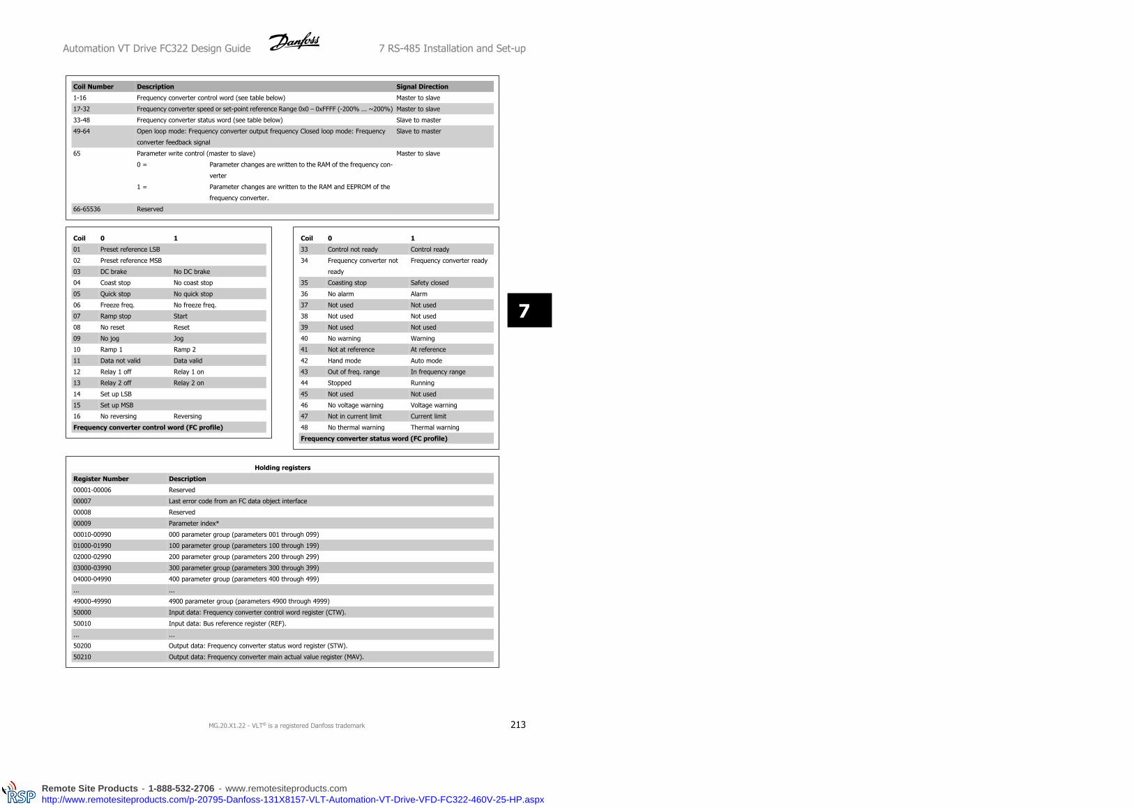
Coil Number Description Signal Direction
1-16 Frequency converter control word (see table below) Master to slave
17-32 Frequency converter speed or set-point reference Range 0x0 – 0xFFFF (-200% ... ~200%) Master to slave
33-48 Frequency converter status word (see table below) Slave to master
49-64 Open loop mode: Frequency converter output frequency Closed loop mode: Frequency
converter feedback signal
Slave to master
65 Parameter write control (master to slave) Master to slave
0 = Parameter changes are written to the RAM of the frequency con-
verter
1 = Parameter changes are written to the RAM and EEPROM of the
frequency converter.
66-65536 Reserved
Coil 0 1
01 Preset reference LSB
02 Preset reference MSB
03 DC brake No DC brake
04 Coast stop No coast stop
05 Quick stop No quick stop
06 Freeze freq. No freeze freq.
07 Ramp stop Start
08 No reset Reset
09 No jog Jog
10 Ramp 1 Ramp 2
11 Data not valid Data valid
12 Relay 1 off Relay 1 on
13 Relay 2 off Relay 2 on
14 Set up LSB
15 Set up MSB
16 No reversing Reversing
Frequency converter control word (FC profile)
Coil 0 1
33 Control not ready Control ready
34 Frequency converter not
ready
Frequency converter ready
35 Coasting stop Safety closed
36 No alarm Alarm
37 Not used Not used
38 Not used Not used
39 Not used Not used
40 No warning Warning
41 Not at reference At reference
42 Hand mode Auto mode
43 Out of freq. range In frequency range
44 Stopped Running
45 Not used Not used
46 No voltage warning Voltage warning
47 Not in current limit Current limit
48 No thermal warning Thermal warning
Frequency converter status word (FC profile)
Holding registers
Register Number Description
00001-00006 Reserved
00007 Last error code from an FC data object interface
00008 Reserved
00009 Parameter index*
00010-00990 000 parameter group (parameters 001 through 099)
01000-01990 100 parameter group (parameters 100 through 199)
02000-02990 200 parameter group (parameters 200 through 299)
03000-03990 300 parameter group (parameters 300 through 399)
04000-04990 400 parameter group (parameters 400 through 499)
... ...
49000-49990 4900 parameter group (parameters 4900 through 4999)
50000 Input data: Frequency converter control word register (CTW).
50010 Input data: Bus reference register (REF).
... ...
50200 Output data: Frequency converter status word register (STW).
50210 Output data: Frequency converter main actual value register (MAV).
Automation VT Drive FC322 Design Guide 7 RS-485 Installation and Set-up
MG.20.X1.22 - VLT® is a registered Danfoss trademark 213
7
Remote Site Products - 1-888-532-2706 - www.remotesiteproducts.comhttp://www.remotesiteproducts.com/p-20795-Danfoss-131X8157-VLT-Automation-VT-Drive-VFD-FC322-460V-25-HP.aspx

* Used to specify the index number to be used when accessing an indexed parameter.
7.8.9 How to Control VLT Automation VT Drive
This section describes codes which can be used in the function and data fields of a Modbus RTU message. For a complete description of all the message
fields please refer to the section Modbus RTU Message Framing Structure.
7 RS-485 Installation and Set-up Automation VT Drive FC322 Design Guide
214 MG.20.X1.22 - VLT® is a registered Danfoss trademark
7
Remote Site Products - 1-888-532-2706 - www.remotesiteproducts.comhttp://www.remotesiteproducts.com/p-20795-Danfoss-131X8157-VLT-Automation-VT-Drive-VFD-FC322-460V-25-HP.aspx
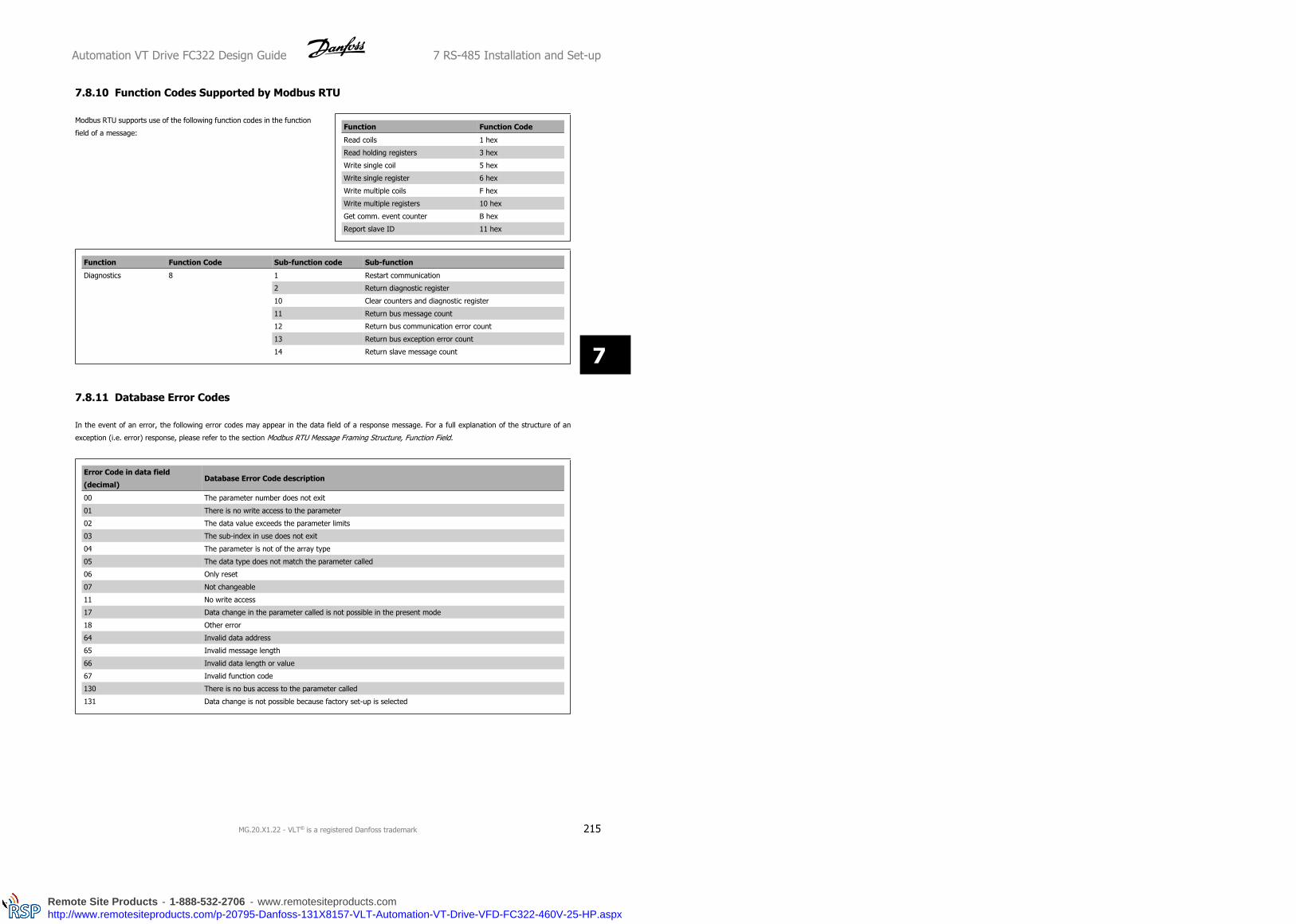
7.8.10 Function Codes Supported by Modbus RTU
Modbus RTU supports use of the following function codes in the function
field of a message:Function Function Code
Read coils 1 hex
Read holding registers 3 hex
Write single coil 5 hex
Write single register 6 hex
Write multiple coils F hex
Write multiple registers 10 hex
Get comm. event counter B hex
Report slave ID 11 hex
Function Function Code Sub-function code Sub-function
Diagnostics 8 1 Restart communication
2 Return diagnostic register
10 Clear counters and diagnostic register
11 Return bus message count
12 Return bus communication error count
13 Return bus exception error count
14 Return slave message count
7.8.11 Database Error Codes
In the event of an error, the following error codes may appear in the data field of a response message. For a full explanation of the structure of an
exception (i.e. error) response, please refer to the section Modbus RTU Message Framing Structure, Function Field.
Error Code in data field
(decimal)Database Error Code description
00 The parameter number does not exit
01 There is no write access to the parameter
02 The data value exceeds the parameter limits
03 The sub-index in use does not exit
04 The parameter is not of the array type
05 The data type does not match the parameter called
06 Only reset
07 Not changeable
11 No write access
17 Data change in the parameter called is not possible in the present mode
18 Other error
64 Invalid data address
65 Invalid message length
66 Invalid data length or value
67 Invalid function code
130 There is no bus access to the parameter called
131 Data change is not possible because factory set-up is selected
Automation VT Drive FC322 Design Guide 7 RS-485 Installation and Set-up
MG.20.X1.22 - VLT® is a registered Danfoss trademark 215
7
Remote Site Products - 1-888-532-2706 - www.remotesiteproducts.comhttp://www.remotesiteproducts.com/p-20795-Danfoss-131X8157-VLT-Automation-VT-Drive-VFD-FC322-460V-25-HP.aspx

7.9 How to Access Parameters
7.9.1 Parameter Handling
The PNU (Parameter Number) is translated from the register address contained in the Modbus read or write message. The parameter number is translated
to Modbus as (10 x parameter number) DECIMAL.
7.9.2 Storage of Data
The Coil 65 decimal determines whether data written to the frequency converter are stored in EEPROM and RAM (coil 65 = 1) or only in RAM (coil 65 =
0).
7.9.3 IND
The array index is set in Holding Register 9 and used when accessing array parameters.
7.9.4 Text Blocks
Parameters stored as text strings are accessed in the same way as the other parameters. The maximum text block size is 20 characters. If a read request
for a parameter is for more characters than the parameter stores, the response is truncated. If the read request for a parameter is for fewer characters
than the parameter stores, the response is space filled.
7.9.5 Conversion Factor
The different attributes for each parameter can be seen in the section on factory settings. Since a parameter value can only be transferred as a whole
number, a conversion factor must be used to transfer decimals. Please refer to the Parameters section.
7.9.6 Parameter Values
Standard Data Types
Standard data types are int16, int32, uint8, uint16 and uint32. They are stored as 4x registers (40001 – 4FFFF). The parameters are read using function
03HEX "Read Holding Registers." Parameters are written using the function 6HEX "Preset Single Register" for 1 register (16 bits), and the function 10HEX
"Preset Multiple Registers" for 2 registers (32 bits). Readable sizes range from 1 register (16 bits) up to 10 registers (20 characters).
Non standard Data Types
Non standard data types are text strings and are stored as 4x registers (40001 – 4FFFF). The parameters are read using function 03HEX "Read Holding
Registers" and written using function 10HEX "Preset Multiple Registers." Readable sizes range from 1 register (2 characters) up to 10 registers (20
characters).
7 RS-485 Installation and Set-up Automation VT Drive FC322 Design Guide
216 MG.20.X1.22 - VLT® is a registered Danfoss trademark
7
Remote Site Products - 1-888-532-2706 - www.remotesiteproducts.comhttp://www.remotesiteproducts.com/p-20795-Danfoss-131X8157-VLT-Automation-VT-Drive-VFD-FC322-460V-25-HP.aspx

7.10 Examples The following examples illustrate various Modbus RTU commands. If an error occurs, please refer to the Exception Codes section.
7.10.1 Read Coil Status (01 HEX)
Description
This function reads the ON/OFF status of discrete outputs (coils) in the frequency converter. Broadcast is never supported for reads.
Query
The query message specifies the starting coil and quantity of coils to be read. Coil addresses start at zero, i.e. coil 33 is addressed as 32.
Example of a request to read coils 33-48 (Status Word) from slave device 01:
Field Name Example (HEX)
Slave Address 01 (frequency converter address)
Function 01 (read coils)
Starting Address HI 00
Starting Address LO 20 (32 decimals) Coil 33
No. of Points HI 00
No. of Points LO 10 (16 decimals)
Error Check (CRC) -
Response
The coil status in the response message is packed as one coil per bit of the data field. Status is indicated as: 1 = ON; 0 = OFF. The LSB of the first data
byte contains the coil addressed in the query. The other coils follow toward the high order end of this byte, and from ‘low order to high order’ in subsequent
bytes.
If the returned coil quantity is not a multiple of eight, the remaining bits in the final data byte will be padded with zeros (toward the high order end of
the byte). The Byte Count field specifies the number of complete bytes of data.
Field Name Example (HEX)
Slave Address 01 (frequency converter address)
Function 01 (read coils)
Byte Count 02 (2 bytes of data)
Data (Coils 40-33) 07
Data (Coils 48-41) 06 (STW=0607hex)
Error Check (CRC) -
Automation VT Drive FC322 Design Guide 7 RS-485 Installation and Set-up
MG.20.X1.22 - VLT® is a registered Danfoss trademark 217
7
Remote Site Products - 1-888-532-2706 - www.remotesiteproducts.comhttp://www.remotesiteproducts.com/p-20795-Danfoss-131X8157-VLT-Automation-VT-Drive-VFD-FC322-460V-25-HP.aspx

7.10.2 Force/Write Single Coil (05 HEX)
Description
This function forces a writes a coil to either ON or OFF. When broadcast the function forces the same coil references in all attached slaves.
Query
The query message specifies the coil 65 (parameter write control) to be forced. Coil addresses start at zero, i.e. coil 65 is addressed as 64. Force Data
= 00 00HEX (OFF) or FF 00HEX (ON).
Field Name Example (HEX)
Slave Address 01 (frequency converter address)
Function 05 (write single coil)
Coil Address HI 00
Coil Address LO 40 (64 decimal) Coil 65
Force Data HI FF
Force Data LO 00 (FF 00 = ON)
Error Check (CRC) -
Response
The normal response is an echo of the query, returned after the coil state has been forced.
Field Name Example (HEX)
Slave Address 01
Function 05
Force Data HI FF
Force Data LO 00
Quantity of Coils HI 00
Quantity of Coils LO 01
Error Check (CRC) -
7 RS-485 Installation and Set-up Automation VT Drive FC322 Design Guide
218 MG.20.X1.22 - VLT® is a registered Danfoss trademark
7
Remote Site Products - 1-888-532-2706 - www.remotesiteproducts.comhttp://www.remotesiteproducts.com/p-20795-Danfoss-131X8157-VLT-Automation-VT-Drive-VFD-FC322-460V-25-HP.aspx
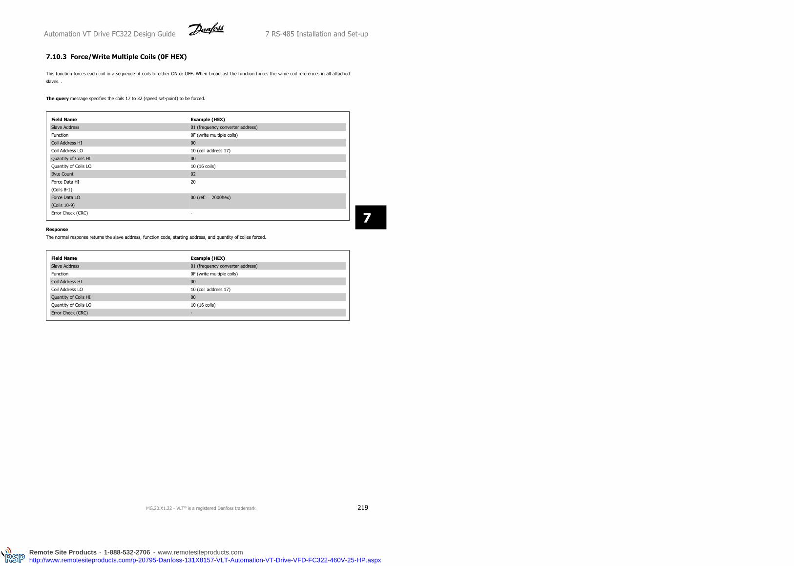
7.10.3 Force/Write Multiple Coils (0F HEX)
This function forces each coil in a sequence of coils to either ON or OFF. When broadcast the function forces the same coil references in all attached
slaves. .
The query message specifies the coils 17 to 32 (speed set-point) to be forced.
Field Name Example (HEX)
Slave Address 01 (frequency converter address)
Function 0F (write multiple coils)
Coil Address HI 00
Coil Address LO 10 (coil address 17)
Quantity of Coils HI 00
Quantity of Coils LO 10 (16 coils)
Byte Count 02
Force Data HI
(Coils 8-1)
20
Force Data LO
(Coils 10-9)
00 (ref. = 2000hex)
Error Check (CRC) -
Response
The normal response returns the slave address, function code, starting address, and quantity of coiles forced.
Field Name Example (HEX)
Slave Address 01 (frequency converter address)
Function 0F (write multiple coils)
Coil Address HI 00
Coil Address LO 10 (coil address 17)
Quantity of Coils HI 00
Quantity of Coils LO 10 (16 coils)
Error Check (CRC) -
Automation VT Drive FC322 Design Guide 7 RS-485 Installation and Set-up
MG.20.X1.22 - VLT® is a registered Danfoss trademark 219
7
Remote Site Products - 1-888-532-2706 - www.remotesiteproducts.comhttp://www.remotesiteproducts.com/p-20795-Danfoss-131X8157-VLT-Automation-VT-Drive-VFD-FC322-460V-25-HP.aspx

7.10.4 Read Holding Registers (03 HEX)
Description
This function reads the contents of holding registers in the slave.
Query
The query message specifies the starting register and quantity of registers to be read. Register addresses start at zero, i.e. registers 1-4 are addressed
as 0-3.
Example: Read par. 3-03, Maximum Reference, register 03030.
Field Name Example (HEX)
Slave Address 01
Function 03 (read holding registers)
Starting Address HI 0B (Register address 3029)
Starting Address LO 05 (Register address 3029)
No. of Points HI 00
No. of Points LO 02 - (Par. 3-03 is 32 bits long, i.e. 2 registers)
Error Check (CRC) -
Response
The register data in the response message are packed as two bytes per register, with the binary contents right justified within each byte. For each register,
the first byte contains the high order bits and the second contains the low order bits.
Field Name Example (HEX)
Slave Address 01
Function 03
Byte Count 04
Data HI
(Register 3030)
00
Data LO
(Register 3030)
16
Data HI
(Register 3031)
E3
Data LO
(Register 3031)
60
Error Check
(CRC)
-
7 RS-485 Installation and Set-up Automation VT Drive FC322 Design Guide
220 MG.20.X1.22 - VLT® is a registered Danfoss trademark
7
Remote Site Products - 1-888-532-2706 - www.remotesiteproducts.comhttp://www.remotesiteproducts.com/p-20795-Danfoss-131X8157-VLT-Automation-VT-Drive-VFD-FC322-460V-25-HP.aspx

7.10.5 Preset Single Register (06 HEX)
Description
This function presets a value into a single holding register.
Query
The query message specifies the register reference to be preset. Register addresses start at zero, i.e. register 1 is addressed as 0.
Example: Write to par. 1-00, register 1000.
Field Name Example (HEX)
Slave Address 01
Function 06
Register Address HI 03 (Register address 999)
Register Address LO E7 (Register address 999)
Preset Data HI 00
Preset Data LO 01
Error Check (CRC) -
Response
Response The normal response is an echo of the query, returned after the register contents have been passed.
Field Name Example (HEX)
Slave Address 01
Function 06
Register Address HI 03
Register Address LO E7
Preset Data HI 00
Preset Data LO 01
Error Check (CRC) -
Automation VT Drive FC322 Design Guide 7 RS-485 Installation and Set-up
MG.20.X1.22 - VLT® is a registered Danfoss trademark 221
7
Remote Site Products - 1-888-532-2706 - www.remotesiteproducts.comhttp://www.remotesiteproducts.com/p-20795-Danfoss-131X8157-VLT-Automation-VT-Drive-VFD-FC322-460V-25-HP.aspx

7.11 Danfoss FC Control Profile
7.11.1 Control Word According to FC Profile(par. 8-10 Control Profile = FC profile)
Bit Bit value = 0 Bit value = 1
00 Reference value external selection lsb
01 Reference value external selection msb
02 DC brake Ramp
03 Coasting No coasting
04 Quick stop Ramp
05 Hold output frequency use ramp
06 Ramp stop Start
07 No function Reset
08 No function Jog
09 Ramp 1 Ramp 2
10 Data invalid Data valid
11 No function Relay 01 active
12 No function Relay 02 active
13 Parameter set-up selection lsb
14 Parameter set-up selection msb
15 No function Reverse
Explanation of the Control Bits
Bits 00/01
Bits 00 and 01 are used to choose between the four reference values, which are pre-programmed in par. 3-10 Preset Reference according to the following
table:
Programmed ref. value Par. Bit 01 Bit 00
1 par. 3-10 Preset Reference [0] 0 0
2 par. 3-10 Preset Reference [1] 0 1
3 par. 3-10 Preset Reference [2] 1 0
4 par. 3-10 Preset Reference [3] 1 1
NB!
Make a selection in par. 8-56 Preset Reference Select to define how Bit 00/01 gates with the corresponding function on the digital
inputs.
Bit 02, DC brake:
7 RS-485 Installation and Set-up Automation VT Drive FC322 Design Guide
222 MG.20.X1.22 - VLT® is a registered Danfoss trademark
7
Remote Site Products - 1-888-532-2706 - www.remotesiteproducts.comhttp://www.remotesiteproducts.com/p-20795-Danfoss-131X8157-VLT-Automation-VT-Drive-VFD-FC322-460V-25-HP.aspx

Bit 02 = ’0’ leads to DC braking and stop. Set braking current and duration in par. 2-01 DC Brake Current and par. 2-02 DC Braking Time. Bit 02 = ’1’
leads to ramping.
Automation VT Drive FC322 Design Guide 7 RS-485 Installation and Set-up
MG.20.X1.22 - VLT® is a registered Danfoss trademark 223
7
Remote Site Products - 1-888-532-2706 - www.remotesiteproducts.comhttp://www.remotesiteproducts.com/p-20795-Danfoss-131X8157-VLT-Automation-VT-Drive-VFD-FC322-460V-25-HP.aspx

Bit 03, Coasting:
Bit 03 = ’0’: The frequency converter immediately "lets go" of the motor, (the output transistors are "shut off") and it coasts to a standstill. Bit 03 = ’1’:
The frequency converter starts the motor if the other starting conditions are met.
NB!
Make a selection in par. 8-50 Coasting Select to define how Bit 03 gates with the corresponding function on a digital input.
Bit 04, Quick stop:
Bit 04 = ’0’: Makes the motor speed ramp down to stop (set in par. 3-81 Quick Stop Ramp Time.
Bit 05, Hold output frequency
Bit 05 = ’0’: The present output frequency (in Hz) freezes. Change the frozen output frequency only by means of the digital inputs (par. 5-10 Terminal
18 Digital Input to par. 5-15 Terminal 33 Digital Input) programmed to Speed up and Slow down.
NB!
If Freeze output is active, the frequency converter can only be stopped by the following:
• Bit 03 Coasting stop
• Bit 02 DC braking
• Digital input (par. 5-10 Terminal 18 Digital Input to par. 5-15 Terminal 33 Digital Input) programmed to DC braking, Coasting
stop, or Reset and coasting stop.
Bit 06, Ramp stop/start:
Bit 06 = ’0’: Causes a stop and makes the motor speed ramp down to stop via the selected ramp down parameter. Bit 06 = ’1’: Permits the frequency
converter to start the motor, if the other starting conditions are met.
NB!
Make a selection in par. 8-53 Start Select to define how Bit 06 Ramp stop/start gates with the corresponding function on a digital input.
Bit 07, Reset: Bit 07 = ’0’: No reset. Bit 07 = ’1’: Resets a trip. Reset is activated on the signal’s leading edge, i.e. when changing from logic ’0’ to logic ’1’.
Bit 08, Jog:
Bit 08 = ’1’: The output frequency is determined by par. 3-19 Jog Speed [RPM].
Bit 09, Selection of ramp 1/2:
Bit 09 = "0": Ramp 1 is active (par. 3-41 Ramp 1 Ramp Up Time to par. 3-42 Ramp 1 Ramp Down Time). Bit 09 = "1": Ramp 2 (par. 3-51 Ramp 2 Ramp
Up Time to par. 3-52 Ramp 2 Ramp Down Time) is active.
Bit 10, Data not valid/Data valid:
Tell the frequency converter whether to use or ignore the control word. Bit 10 = ’0’: The control word is ignored. Bit 10 = ’1’: The control word is used.
This function is relevant because the telegram always contains the control word, regardless of the telegram type. Thus, you can turn off the control word
if you do not want to use it when updating or reading parameters.
Bit 11, Relay 01:
Bit 11 = "0": Relay not activated. Bit 11 = "1": Relay 01 activated provided that Control word bit 11 is chosen in par. 5-40 Function Relay.
7 RS-485 Installation and Set-up Automation VT Drive FC322 Design Guide
224 MG.20.X1.22 - VLT® is a registered Danfoss trademark
7
Remote Site Products - 1-888-532-2706 - www.remotesiteproducts.comhttp://www.remotesiteproducts.com/p-20795-Danfoss-131X8157-VLT-Automation-VT-Drive-VFD-FC322-460V-25-HP.aspx

Bit 12, Relay 04:
Bit 12 = "0": Relay 04 is not activated. Bit 12 = "1": Relay 04 is activated provided that Control word bit 12 is chosen in par. 5-40 Function Relay.
Automation VT Drive FC322 Design Guide 7 RS-485 Installation and Set-up
MG.20.X1.22 - VLT® is a registered Danfoss trademark 225
7
Remote Site Products - 1-888-532-2706 - www.remotesiteproducts.comhttp://www.remotesiteproducts.com/p-20795-Danfoss-131X8157-VLT-Automation-VT-Drive-VFD-FC322-460V-25-HP.aspx

Bit 13/14, Selection of set-up:
Use bits 13 and 14 to choose from the four menu set-ups according to
the shown table: .
Set-up Bit 14 Bit 13
1 0 0
2 0 1
3 1 0
4 1 1
The function is only possible when Multi Set-Ups is selected in
par. 0-10 Active Set-up.NB!
Make a selection in par. 8-55 Set-up Select to define
how Bit 13/14 gates with the corresponding function
on the digital inputs.
Bit 15 Reverse:
Bit 15 = ’0’: No reversing. Bit 15 = ’1’: Reversing. In the default setting, reversing is set to digital in par. 8-54 Reversing Select. Bit 15 causes reversing
only when Ser. communication, Logic or or Logic and is selected.
7.11.2 Status Word According to FC Profile (STW) (par. 8-10 Control Profile = FC profile)
Bit Bit = 0 Bit = 1
00 Control not ready Control ready
01 Drive not ready Drive ready
02 Coasting Enable
03 No error Trip
04 No error Error (no trip)
05 Reserved -
06 No error Triplock
07 No warning Warning
08 Speed ≠ reference Speed = reference
09 Local operation Bus control
10 Out of frequency limit Frequency limit OK
11 No operation In operation
12 Drive OK Stopped, auto start
13 Voltage OK Voltage exceeded
14 Torque OK Torque exceeded
15 Timer OK Timer exceeded
Explanation of the Status Bits
Bit 00, Control not ready/ready:
Bit 00 = ’0’: The frequency converter trips. Bit 00 = ’1’: The frequency converter controls are ready but the power component does not necessarily receive
any power supply (in case of external 24 V supply to controls).
Bit 01, Drive ready:
7 RS-485 Installation and Set-up Automation VT Drive FC322 Design Guide
226 MG.20.X1.22 - VLT® is a registered Danfoss trademark
7
Remote Site Products - 1-888-532-2706 - www.remotesiteproducts.comhttp://www.remotesiteproducts.com/p-20795-Danfoss-131X8157-VLT-Automation-VT-Drive-VFD-FC322-460V-25-HP.aspx
Bit 01 = ’1’: The frequency converter is ready for operation but the coasting command is active via the digital inputs or via serial communication.
Bit 02, Coasting stop:
Bit 02 = ’0’: The frequency converter releases the motor. Bit 02 = ’1’: The frequency converter starts the motor with a start command.
Bit 03, No error/trip:
Bit 03 = ’0’ : The frequency converter is not in fault mode. Bit 03 = ’1’: The frequency converter trips. To re-establish operation, enter [Reset].
Bit 04, No error/error (no trip):
Bit 04 = ’0’: The frequency converter is not in fault mode. Bit 04 = “1”: The frequency converter shows an error but does not trip.
Bit 05, Not used:
Bit 05 is not used in the status word.
Bit 06, No error / triplock:
Bit 06 = ’0’: The frequency converter is not in fault mode. Bit 06 = “1”: The frequency converter is tripped and locked.
Bit 07, No warning/warning:
Bit 07 = ’0’: There are no warnings. Bit 07 = ’1’: A warning has occurred.
Bit 08, Speed≠ reference/speed = reference:
Bit 08 = ’0’: The motor is running but the present speed is different from the preset speed reference. It might e.g. be the case when the speed ramps
up/down during start/stop. Bit 08 = ’1’: The motor speed matches the preset speed reference.
Bit 09, Local operation/bus control:
Bit 09 = ’0’: [STOP/RESET] is activate on the control unit or Local control in par. 3-13 Reference Site is selected. You cannot control the frequency
converter via serial communication. Bit 09 = ’1’ It is possible to control the frequency converter via the fieldbus/ serial communication.
Bit 10, Out of frequency limit:
Bit 10 = ’0’: The output frequency has reached the value in par. 4-11 Motor Speed Low Limit [RPM] or par. 4-13 Motor Speed High Limit [RPM]. Bit 10
= "1": The output frequency is within the defined limits.
Bit 11, No operation/in operation:
Bit 11 = ’0’: The motor is not running. Bit 11 = ’1’: The frequency converter has a start signal or the output frequency is greater than 0 Hz.
Bit 12, Drive OK/stopped, autostart:
Bit 12 = ’0’: There is no temporary over temperature on the inverter. Bit 12 = ’1’: The inverter stops because of over temperature but the unit does not
trip and will resume operation once the over temperature stops.
Bit 13, Voltage OK/limit exceeded:
Bit 13 = ’0’: There are no voltage warnings. Bit 13 = ’1’: The DC voltage in the frequency converter’s intermediate circuit is too low or too high.
Bit 14, Torque OK/limit exceeded:
Bit 14 = ’0’: The motor current is lower than the torque limit selected in par. 4-18 Current Limit. Bit 14 = ’1’: The torque limit in par. 4-18 Current
Limit is exceeded.
Bit 15, Timer OK/limit exceeded:
Bit 15 = ’0’: The timers for motor thermal protection and thermal protection are not exceeded 100%. Bit 15 = ’1’: One of the timers exceeds 100%.
Automation VT Drive FC322 Design Guide 7 RS-485 Installation and Set-up
MG.20.X1.22 - VLT® is a registered Danfoss trademark 227
7
Remote Site Products - 1-888-532-2706 - www.remotesiteproducts.comhttp://www.remotesiteproducts.com/p-20795-Danfoss-131X8157-VLT-Automation-VT-Drive-VFD-FC322-460V-25-HP.aspx

NB!
All bits in the STW are set to ’0’ if the connection between the Interbus option and the frequency converter is lost, or an internal
communication problem has occurred.
7 RS-485 Installation and Set-up Automation VT Drive FC322 Design Guide
228 MG.20.X1.22 - VLT® is a registered Danfoss trademark
7
Remote Site Products - 1-888-532-2706 - www.remotesiteproducts.comhttp://www.remotesiteproducts.com/p-20795-Danfoss-131X8157-VLT-Automation-VT-Drive-VFD-FC322-460V-25-HP.aspx

7.11.3 Bus Speed Reference Value
Speed reference value is transmitted to the frequency converter in a rel-
ative value in %. The value is transmitted in the form of a 16-bit word;
in integers (0-32767) the value 16384 (4000 Hex) corresponds to 100%.
Negative figures are formatted by means of 2’s complement. The Actual
Output frequency (MAV) is scaled in the same way as the bus reference.
The reference and MAV are scaled as follows:
Automation VT Drive FC322 Design Guide 7 RS-485 Installation and Set-up
MG.20.X1.22 - VLT® is a registered Danfoss trademark 229
7
Remote Site Products - 1-888-532-2706 - www.remotesiteproducts.comhttp://www.remotesiteproducts.com/p-20795-Danfoss-131X8157-VLT-Automation-VT-Drive-VFD-FC322-460V-25-HP.aspx

8 Troubleshooting Automation VT Drive FC322 Design Guide
230 MG.20.X1.22 - VLT® is a registered Danfoss trademark
8
Remote Site Products - 1-888-532-2706 - www.remotesiteproducts.comhttp://www.remotesiteproducts.com/p-20795-Danfoss-131X8157-VLT-Automation-VT-Drive-VFD-FC322-460V-25-HP.aspx

8 Troubleshooting
A warning or an alarm is signalled by the relevant LED on the front of the frequency converter and indicated by a code on the display.
A warning remains active until its cause is no longer present. Under certain circumstances operation of the motor may still be continued. Warning messages
may be critical, but are not necessarily so.
In the event of an alarm, the frequency converter will have tripped. Alarms must be reset to restart operation once their cause has been rectified.
This may be done in four ways:
1. By using the [RESET] control button on the LCP control panel.
2. Via a digital input with the “Reset” function.
3. Via serial communication/optional fieldbus.
4. By resetting automatically using the [Auto Reset] function, which is a default setting for VLT Automation VT Drive Drive. see par. 14-20 Reset
Mode inVLT Automation VT Drive Programming Guide
NB!
After a manual reset using the [RESET] button on the LCP, the [AUTO ON] or [HAND ON] button must be pressed to restart the motor.
If an alarm cannot be reset, the reason may be that its cause has not been rectified, or the alarm is trip-locked (see also table on following page).
Alarms that are trip-locked offer additional protection, means that the mains supply must be switched off before the alarm can be reset. After being
switched back on, the frequency converter is no longer blocked and may be reset as described above once the cause has been rectified.
Alarms that are not trip-locked can also be reset using the automatic reset function in par. 14-20 Reset Mode (Warning: automatic wake-up is possible!)
If a warning and alarm is marked against a code in the table on the following page, this means that either a warning occurs before an alarm, or it can
be specified whether it is a warning or an alarm that is to be displayed for a given fault.
This is possible, for instance, in par. 1-90 Motor Thermal Protection. After an alarm or trip, the motor carries on coasting, and the alarm and warning
flash on the frequency converter. Once the problem has been rectified, only the alarm continues flashing.
Automation VT Drive FC322 Design Guide 8 Troubleshooting
MG.20.X1.22 - VLT® is a registered Danfoss trademark 231
8
Remote Site Products - 1-888-532-2706 - www.remotesiteproducts.comhttp://www.remotesiteproducts.com/p-20795-Danfoss-131X8157-VLT-Automation-VT-Drive-VFD-FC322-460V-25-HP.aspx

No. Description Warning Alarm/Trip Alarm/Trip Lock Parameter Reference
1 10 Volts low X
2 Live zero error (X) (X) 6-01
3 No motor (X) 1-80
4 Mains phase loss (X) (X) (X) 14-12
5 DC link voltage high X
6 DC link voltage low X
7 DC over voltage X X
8 DC under voltage X X
9 Inverter overloaded X X
10 Motor ETR over temperature (X) (X) 1-90
11 Motor thermistor over temperature (X) (X) 1-90
12 Torque limit X X
13 Over Current X X X
14 Earth fault X X X
15 Hardware mismatch X X
16 Short Circuit X X
17 Control word timeout (X) (X) 8-04
23 Internal Fan Fault X
24 External Fan Fault X 14-53
25 Brake resistor short-circuited X
26 Brake resistor power limit (X) (X) 2-13
27 Brake chopper short-circuited X X
28 Brake check (X) (X) 2-15
29 Drive over temperature X X X
30 Motor phase U missing (X) (X) (X) 4-58
31 Motor phase V missing (X) (X) (X) 4-58
32 Motor phase W missing (X) (X) (X) 4-58
33 Inrush fault X X
34 Fieldbus communication fault X X
35 Out of frequency range X X
36 Mains failure X X
37 Phase Imbalance X X
38 Internal fault X X
39 Heatsink sensor X X
40 Overload of Digital Output Terminal 27 (X) 5-00, 5-01
41 Overload of Digital Output Terminal 29 (X) 5-00, 5-02
42 Overload of Digital Output On X30/6 (X) 5-32
42 Overload of Digital Output On X30/7 (X) 5-33
46 Pwr. card supply X X
47 24 V supply low X X X
48 1.8 V supply low X X
49 Speed limit X
50 AMA calibration failed X
51 AMA check Unom and Inom X
52 AMA low Inom X
53 AMA motor too big X
54 AMA motor too small X
55 AMA parameter out of range X
56 AMA interrupted by user X
57 AMA timeout X
58 AMA internal fault X X
59 Current limit X
8 Troubleshooting Automation VT Drive FC322 Design Guide
232 MG.20.X1.22 - VLT® is a registered Danfoss trademark
8
Remote Site Products - 1-888-532-2706 - www.remotesiteproducts.comhttp://www.remotesiteproducts.com/p-20795-Danfoss-131X8157-VLT-Automation-VT-Drive-VFD-FC322-460V-25-HP.aspx

No. Description Warning Alarm/Trip Alarm/Trip Lock Parameter Reference
60 External Interlock X
62 Output Frequency at Maximum Limit X
64 Voltage Limit X
65 Control Board Over-temperature X X X
66 Heat sink Temperature Low X
67 Option Configuration has Changed X
68 Safe Stop Activated X1)
69 Pwr. Card Temp X X
70 Illegal FC configuration X
71 PTC 1 Safe Stop X X1)
72 Dangerous Failure X1)
73 Safe Stop Auto Restart
79 Illegal PS config X X
80 Drive Initialised to Default Value X
91 Analog input 54 wrong settings X
92 NoFlow X X 22-2*
93 Dry Pump X X 22-2*
94 End of Curve X X 22-5*
95 Broken Belt X X 22-6*
96 Start Delayed X 22-7*
97 Stop Delayed X 22-7*
98 Clock Fault X 0-7*
220 Overload Trip X
243 Brake IGBT X X
244 Heatsink temp X X X
245 Heatsink sensor X X
246 Pwr.card supply X X
247 Pwr.card temp X X
248 Illegal PS config X X
250 New spare part X
251 New Type Code X X
Table 8.1: Alarm/Warning code list
(X) Dependent on parameter
1) Can not be Auto reset via par. 14-20 Reset Mode
A trip is the action when an alarm has appeared. The trip will coast the motor and can be reset by pressing the reset button or make a reset by a digital
input (Par. 5-1* [1]). The origin event that caused an alarm cannot damage the frequency converter or cause dangerous conditions. A trip lock is an
action when an alarm occurs, which may cause damage to frequency converter or connected parts. A Trip Lock situation can only be reset by a power
cycling.
LED indication
Warning yellow
Alarm flashing red
Trip locked yellow and red
Automation VT Drive FC322 Design Guide 8 Troubleshooting
MG.20.X1.22 - VLT® is a registered Danfoss trademark 233
8
Remote Site Products - 1-888-532-2706 - www.remotesiteproducts.comhttp://www.remotesiteproducts.com/p-20795-Danfoss-131X8157-VLT-Automation-VT-Drive-VFD-FC322-460V-25-HP.aspx

Alarm Word and Extended Status Word
Bit Hex Dec Alarm Word Warning Word Extended Status Word
0 00000001 1 Brake Check Brake Check Ramping
1 00000002 2 Pwr. Card Temp Pwr. Card Temp AMA Running
2 00000004 4 Earth Fault Earth Fault Start CW/CCW
3 00000008 8 Ctrl.Card Temp Ctrl.Card Temp Slow Down
4 00000010 16 Ctrl. Word TO Ctrl. Word TO Catch Up
5 00000020 32 Over Current Over Current Feedback High
6 00000040 64 Torque Limit Torque Limit Feedback Low
7 00000080 128 Motor Th Over Motor Th Over Output Current High
8 00000100 256 Motor ETR Over Motor ETR Over Output Current Low
9 00000200 512 Inverter Overld. Inverter Overld. Output Freq High
10 00000400 1024 DC under Volt DC under Volt Output Freq Low
11 00000800 2048 DC over Volt DC over Volt Brake Check OK
12 00001000 4096 Short Circuit DC Voltage Low Braking Max
13 00002000 8192 Inrush Fault DC Voltage High Braking
14 00004000 16384 Mains ph. Loss Mains ph. Loss Out of Speed Range
15 00008000 32768 AMA Not OK No Motor OVC Active
16 00010000 65536 Live Zero Error Live Zero Error
17 00020000 131072 Internal Fault 10V Low
18 00040000 262144 Brake Overload Brake Overload
19 00080000 524288 U phase Loss Brake Resistor
20 00100000 1048576 V phase Loss Brake IGBT
21 00200000 2097152 W phase Loss Speed Limit
22 00400000 4194304 Fieldbus Fault Fieldbus Fault
23 00800000 8388608 24 V Supply Low 24V Supply Low
24 01000000 16777216 Mains Failure Mains Failure
25 02000000 33554432 1.8V Supply Low Current Limit
26 04000000 67108864 Brake Resistor Low Temp
27 08000000 134217728 Brake IGBT Voltage Limit
28 10000000 268435456 Option Change Unused
29 20000000 536870912 Drive Initialised Unused
30 40000000 1073741824 Safe Stop Unused
Table 8.2: Description of Alarm Word, Warning Word and Extended Status Word
The alarm words, warning words and extended status words can be read out via serial bus or optional fieldbus for diagnosis. See also par. 16-90 Alarm
Word, par. 16-92 Warning Word and par. 16-94 Ext. Status Word.
8 Troubleshooting Automation VT Drive FC322 Design Guide
234 MG.20.X1.22 - VLT® is a registered Danfoss trademark
8
Remote Site Products - 1-888-532-2706 - www.remotesiteproducts.comhttp://www.remotesiteproducts.com/p-20795-Danfoss-131X8157-VLT-Automation-VT-Drive-VFD-FC322-460V-25-HP.aspx