vlsi vax micro-architecture - simhsimh.trailing-edge.com/docs/microarch.pdf• performs instruction...
TRANSCRIPT

VLSI VAX
Micro-architecture
May 1988
Bob Supnik
For Internal Use Only
Semiconductor Engineering Group

Contents
• The macro-architectural issues
• The canonical micro-architectural model
• MicroVAX
• Improving performance
• CVAX and Rigel
• Summary
VLSI VAX Micro-architecture

The VAX Architecture
• The VAX architecture is a complex instruction set computer
(CISC) characterized by:
– Irregular instruction format (1 to 50+ bytes)
– Large instruction set (304 instructions)
– Multiple addressing modes (21)
– Demand paged virtual memory management
– Few hardware limitations on software
• TTL/ECL implementations have typically been characterized
by:
– Complex microcode-based control
– Large control store (400k bits to 2200k bits)
– Redundant facilities (microcoded and hardware floating
point)
– Inbuilt console I/O
– Complex memory subsystem (large TB, large cache)
• These implementation characteristics pose severe problems for a
single chip VLSI implementation.
VLSI VAX Micro-architecture

The MicroVAX Subset
• Generically, the MicroVAX subset is a set of hardware/ mi-
crocode/ software/ performance tradeoffs intended to facilitate
VLSI implementation.
• Firmware to software tradeoffs:
– 59 instructions implemented in macrocode rather than mi-
crocode: character string, decimal, EDITPC, CRC, octa-
word, h-floating
– Console implemented in macrocode rather than microcode
• Firmware to hardware tradeoffs:
– Hardware floating point only
• Performance tradeoffs:
– Small translation buffer, fully associative, fast replacement
– No cache or small cache
VLSI VAX Micro-architecture

The Canonical VAX Micro-model
• Most VAX implementations, including the 78X, 750, 730, V-11,
MicroVAX, CVAX, Rigel, and Nautilus, have the same basic
block structure:
– I(nstruction) box
– E(xecution) box
– M(emory) box
– Microsequencer/ control store
– Bus interface unit
– Interrupts
– Memory subsystem
– Console subsystem
VLSI VAX Micro-architecture

I Box
• Parses and decodes instruction stream using internal state and
prefetch queue data fetched by the M Box and BIU.
• Gives “VAXness” to the rest of the chip by directing the Microse-
quencer through specifier evaluation and instruction execution.
• Supplies parameters to specifier evaluation.
• Formats I-stream data for specifier evaluation and instruction
execution.
VLSI VAX Micro-architecture

E Box
• Contains main execution data path:
– Register file
– ALU and shifter
• Under microcode control, performs:
– Specifier evaluation
– Instruction execution
– Interrupts and exceptions
– Memory management processing
• Maintains PC, backup PC, PSL, GPRs, RLOG, and other ar-
chitecturally specified state.
VLSI VAX Micro-architecture

M Box
• Performs address translation and access checking.
• Decodes and initiates memory references, TB accesses.
• Maintains address registers.
• Performs instruction prefetching when idle.
VLSI VAX Micro-architecture

Microsequencer/ Control Store
• Forms next micro-word address and performs micro-word se-
quencing and access.
• Decodes and selects micro-branch conditions.
• Evaluates requests and initiates micro-traps.
• Maintains micro-stack and pointer.
VLSI VAX Micro-architecture

BIU
• Controls DAL and other external interfaces pins.
• Controls DAL latches and rotators for proper positioning and
formatting of incoming and outgoing data.
• Cooperates with M Box in processing of unaligned data.
• Provides autonomous operation on selected I/O functions.
VLSI VAX Micro-architecture

Other
• Interrupt section responds to external hardware and internal
software interrupt requests.
• Memory subsystem provides connection of processor to external
storage (memory and I/O).
• Console subsystem provides diagnostic and control interface to
entire system.
• Note: Console subsystem ise external in VLSI VAXen and will
not be discussed.
VLSI VAX Micro-architecture

Canonical VAX Problems
• All VAX implementations must wrestle with thorny implemen-
tation problems posed by the architecture, including:
– Variable length instructions
– Unaligned data
– Virtual memory management
– Instructions with multiple destinations
– Instructions with complex algorithms
– Exceptions
– Clocking and stalls
• It is interesting to note that there is no reasonable relationship
between the difficulty of implementing a feature and its impor-
tance.
VLSI VAX Micro-architecture

MicroVAX Overview
• MicroVAX was the first single chip implementation of the VAX.
Its characteristics included:
– Single chip MicroVAX subset CPU (175 instructions) plus
companion floating point unit (70 instructions)
– ZMOS process (3u drawn, NMOS, double level metal)
– 125,000 transistors, 353 mils x 358 mils
– 200ns microcycle, 400ns I/O cycle
– 8 entry TB, no cache
– 1600 x 39b control store
– PG - 2/84, LR - 3/85, FRS - 5/85
• MicroVAX implemented a simple external interface:
– Multiplexed data and address bus (DAL)
– Address and data strobes (AS, DS)
– Byte masks for masked writes (BM<3:0>)
– Cycle status for I/O differentiatiion (CS<2:0>, WR)
– DMA request and grant (DMR, DMG)
• MicroVAX drew heavily on the only VLSI full VAX (V-11) for its
micro-architectural inspiration (E Box, micro-word, clocking).
VLSI VAX Micro-architecture

MicroVAX I Box
• Principal function: prefetch, parse, and decode instructions.
• Prefetch queue:
– 8 bytes (2 aligned longwords)
– Maximum of 4 bytes retired per microcycle
• Instruction data register:
– Data link from I Box to E Box
– Automatically loaded for simple conditional branches, byte/
word displacements, short literals
– Manually loaded for complex conditional branches, longword
displacements, immediates, absolute addresses
• Decode logic:
– Decode PLAs for exceptions, instructions, specifiers
– Initial decode PLA (IPLA) to supply instruction parameters
to specifier flows
• Control registers:
– Opcode register
– Access type/ data length register
– Current GPR register
VLSI VAX Micro-architecture

MicroVAX Instruction Decode
initial instruction decode
|
+---------------+---------------+
| | |
exception direct first
dispatch execution specifier
dispatch decode
|
+---------------+
|
next specifier decode
|
+---------------+
| |
execution second
dispatch specifier
decode
|
+---------------+
|
execution
dispatch
VLSI VAX Micro-architecture
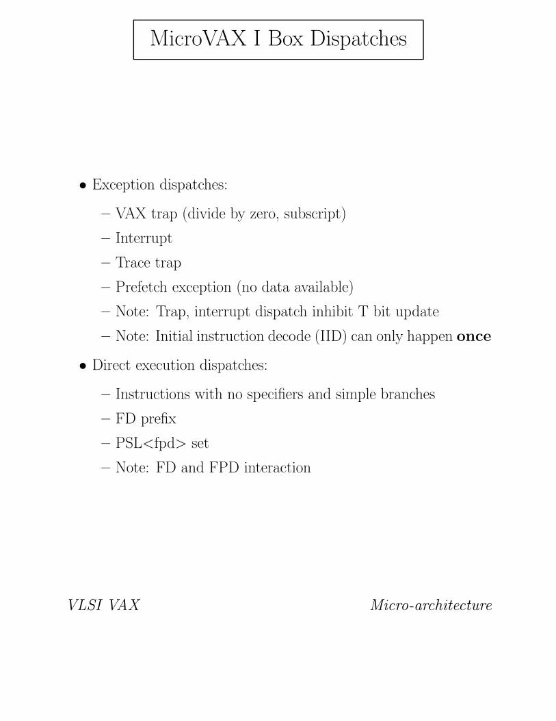
MicroVAX I Box Dispatches
• Exception dispatches:
– VAX trap (divide by zero, subscript)
– Interrupt
– Trace trap
– Prefetch exception (no data available)
– Note: Trap, interrupt dispatch inhibit T bit update
– Note: Initial instruction decode (IID) can only happen once
• Direct execution dispatches:
– Instructions with no specifiers and simple branches
– FD prefix
– PSL<fpd> set
– Note: FD and FPD interaction
VLSI VAX Micro-architecture

I Box Dispatches, continued
• Specifier dispatches:
– Short literal
– Register
– Indexed
– Register deferred
– Autodecrement
– Autoincrement
– Immediate
– Autoincrement deferred
– Absolute
– Byte/ word displacement and relative
– Byte/ word displacement and relative deferred
– Longword displacement and relative
– Longword displacement and relative deferred
– Note: Separate longword dispatch due to 4 bytes per cycle
limit on prefetchq queue
VLSI VAX Micro-architecture

MicroVAX Decode Flow
EXAMPLE: ADDL3 R4, l^disp(R5), (R6)+
initial instruction decode --> first spec decode
W[0] := GPR[Rn] ! Flow for first spec
next specifier decode --> second specifier decode
IDR := IB.LONG and case ! Flow for second spec
VA := GPR[Rn] + IDR
W[2] := MEM(VA)
next specifier decode --> execution dispatch
W[0] := W[0] + W[2] ! Execution
microcode dispatch to write destination
VA := GPR[Rn] ! Flow for third spec
GPR[Rn]:= GPR[Rn] + 4
MEM(VA):= W[0] ! End of instruction
VLSI VAX Micro-architecture

MicroVAX E Box
• Principal function: Execute VAX macro-instructions.
• Register file:
– 15 single ported general purpose registers (GPR’s): R0 - R14
– 12 single ported temporary registers (T’s): IS, P0BR, P1BR,
SBR, SISR, PSL, etc.
– 7 dual ported working registers (W’s): microcode tempo-
raries
• Program counter:
– Architectural PC (R15)
– Backup PC, loaded at IID from PC, for exception recovery
– PC adder, for incrementing PC during instruction parse
• Constant generator:
– Literal constants from micro-word
– Fixed constants (0, 1, 4)
– State dependent constants (KDL, SEXTN)
VLSI VAX Micro-architecture

MicroVAX E Box, continued
• SC/Q register:
– Working register (W7)
– Shift counter to control barrel shifter
– Multiplier/quotient register
– Case generation register
• Arithmetic/ logical unit (ALU):
– 32b arithmetic and logic function unit
– Condition code outputs for 8b, 16b, 32b results
• Barrel shifter:
– 64b in, 32b out funnel shifter
– Right shift in hardware
– Left shift by ‘32-n’ right shift
VLSI VAX Micro-architecture

MicroVAX E Box, continued
• Condition code logic:
– ‘Raw’ ALU condition codes for microcode testing
– Architecturally defined PSL condition codes
– Instruction specified condition code ‘map’ raw condition
codes to architecturally specified condition codes
– Override for developing multi-word condition codes
• Conditional branch logic:
– Maps opcode against ALU/ PSL condition codes
– Generates ‘branch taken’ for conditional update of PC
• State logic:
– Microcode settable/ testable flags
– Half are global, half are cleared at IID
• Register logging stack:
– Records autoincrement/ autodecrement modifications to
GPRs
– Used in exception recovery
– Cleared at IID
VLSI VAX Micro-architecture

MicroVAX M Box
• Principal function: Address translation and external I/O.
• Address registers:
– VA - address register for data
– VA’ - backup address register for data, autoincrements
– VIBA - address register for instructions, autoincrements
• Length check logic:
– SLR, P0LR, P1LR - architecturally specified length registers
– Length comparator
– Status output - only tested on TB miss
• Translation buffer:
– Tag store (CAM) looks up addresses, fully associative
– Data store (PTEs) holds corresponding PTEs
– Management algorithm is true LRU
VLSI VAX Micro-architecture

MicroVAX M Box, continued
• Access check logic:
– Validity check (PTE.V # 0) and micro-trap
– Access (privilege) check and micro-trap
– M = 0 check and micro-trap
– Note: probe vs memory request
– Note: read vs read check, write vs write check
• Unaligned logic:
– Checks for data transfer across longword boundary
– Breaks transfer into two transfers with proper data rotation
and latching
• Cross page logic:
– Checks for data transfer across page boundary
– Initiates micro-trap for proper access check
• Data length logic - drives data length on DAL.
• Micro-trap and abort logic.
VLSI VAX Micro-architecture
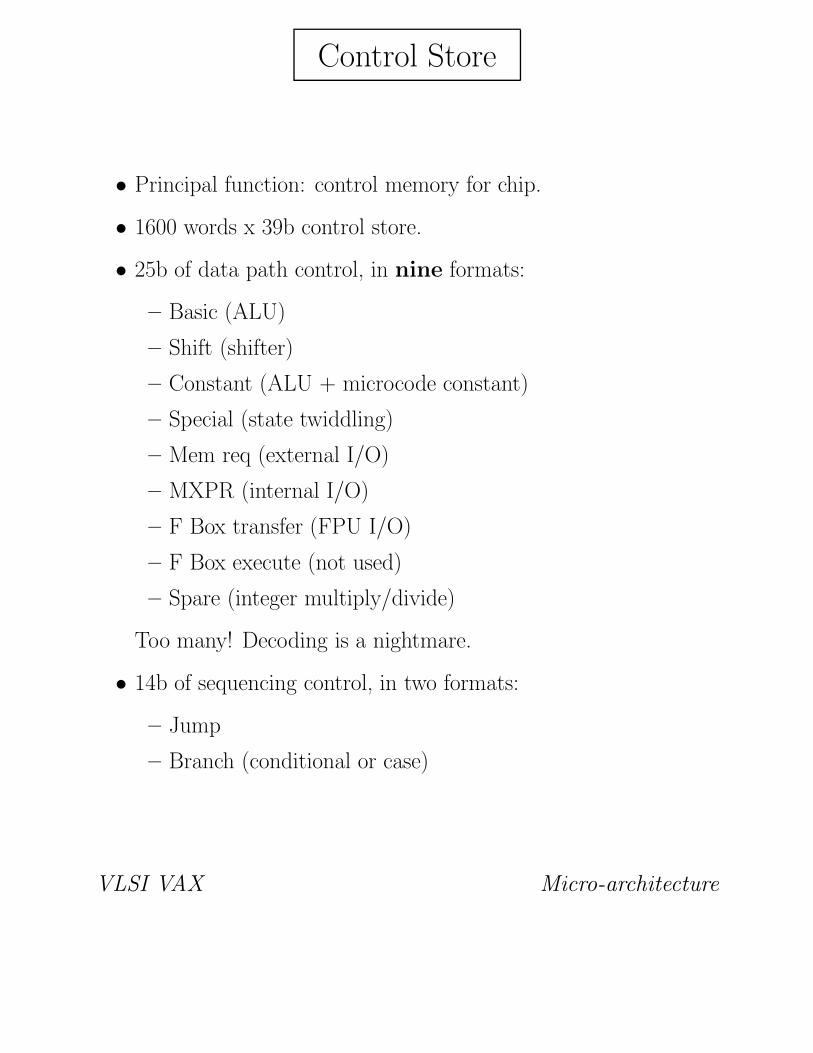
Control Store
• Principal function: control memory for chip.
• 1600 words x 39b control store.
• 25b of data path control, in nine formats:
– Basic (ALU)
– Shift (shifter)
– Constant (ALU + microcode constant)
– Special (state twiddling)
– Mem req (external I/O)
– MXPR (internal I/O)
– F Box transfer (FPU I/O)
– F Box execute (not used)
– Spare (integer multiply/divide)
Too many! Decoding is a nightmare.
• 14b of sequencing control, in two formats:
– Jump
– Branch (conditional or case)
VLSI VAX Micro-architecture

Microsequencer
• Principal function: sequence access of micro-words from control
store.
• Provides multiple access modes:
– Absolute next address
– Relative next address (signed offset)
– Sequential next address (micro-PC + 1)
– Conditional branch
– Case branch
– Micro-subroutine and return
– Externally generated address (test mode)
• Maintains micro-PC (11b), micro-stack (8 entries).
• Mediates and generates micro-traps:
– M Box - TB miss, ACV/TNV, M = 0, cross page
– E Box - integer overflow
– I Box - reserved opcode
– BIU - floating point error, DAL error
VLSI VAX Micro-architecture

BIU
• Principal function: control external I/O.
• Sequences external I/O functions:
– Data and interrupt vector read, instruction prefetch
– Data write with overlap (write and run)
– FPU transfer
– DMA request and grant
• Controls data formatting:
– Write data rotators
– Read data rotators, latches, zero extender
– Byte mask pins
VLSI VAX Micro-architecture

Interrupts and Clocks
• Interrupt logic mediates external and internal interrupts:
– External hardwired interrupts - HALT, PWRFL
– External vectored interrupts - IRQ<3:0> = IPL<17:14>
– Interval timer interrupt and disable flag - ICCS<6>
Internal software interrupts - SISR<15:1> = IPL<0F:01> - are
implemented entirely in microcode.
• Clock logic provides master clocks for all chip logic:
– Divide by two logic for internal master clock
– Clock generators for 8 two phase internal clocks
– Reset and synchronization logic
Too complicated!
VLSI VAX Micro-architecture

Improving Performance
• MicroVAX, like the 11/780, runs at about 500,000 VAX instruc-
tions per second:
– Average 10 microcycles per macro-instruction
– 200ns microcycles
– Average macro-instructions is 2.0 microseconds
• To improve performance, there are two, and only two, techniques
that can be tried:
– Shorten the microcycle
∗ by improving technology
∗ by pipelining micro-instructions
– Reduce the number of microcycles (ticks) per instruction
(tpi)
∗ by improved macro-level parallelism
∗ by piecemeal improvement
VLSI VAX Micro-architecture

Faster Microcycles: Technology
• There are four critical loops in a VAX implementation:
– The E Box loop (register read, ALU, register write)
– The I Box loop (data in, decode, micro-address out)
– The Microsequencer loop (control store access, next address
decode)
– The TB/cache loop (address out, translation, access, data
in)
• In MicroVAX, each of these loops is balanced around a 200ns
period.
• Each generation of technology provides approximately 30% faster
gates.
• Therefore, successive generations of VLSI VAXen can speed up
by 30% on technology alone.
Can’t we do better than that?
VLSI VAX Micro-architecture

Faster Microcycles: Pipelining
By pipelining the E Box microcycle, micro-instruction through-
put can be dramatically increased, thereby reducing the apparent
microcycle time.
unfolded (1X):
read ALU write
+------+------+------+
half folded (1.5X):
read ALU write
+------+------+------+
read ALU write
+------+------+------+
fully folded (3X):
read ALU write
+------+------+------+
read ALU write
+------+------+------+
read ALU write
+------+------+------+
VLSI VAX Micro-architecture

Micro-pipelining, continued
• Micro-pipelining impacts entire micro-architecture:
– I Box must be pipelined to meet apparent faster microcycle
– Microsequencer and control store must get faster to meet
apparent faster microcycle
– TB/cache must get faster to meet apparent faster microcycle
– Control becomes much more complex throughout due to for-
mal pipeline controls, stalls, etc
– Microcode becomes much more complex due to longer micro-
branch latencies, pipeline side effects, etc
• Micro-pipelining is not a perfect win:
– Segments are not equal length, effective microcycle time de-
termined by longest segment
– Pipeline introduces some inefficiencies and stalls
• Micro-pipelining provides the biggest ‘multiplier’ for improving
VAX performance; but where do we go after fully folding?
VLSI VAX Micro-architecture

Reduced TPI: Pipelining
• The high TPI of most VAXen is due to two primary factors:
– Serial decoding of specifiers
– Lengthy execution times of complex instructions (CALLx,
RET, etc)
• Increasing macro-level parallelism could reduce apparent TPI by:
– Parallel decoding of multiple specifiers, or
– Overlap of specifier decoding with instruction execution
• However, the VAX architecture is highly resistant to macro-
level parallelism:
– Variable length specifiers make parallel decoding of specifiers
difficult and expensive
– Interlocks within and between instructions make overlap of
specifiers with instruction execution difficult and expensive
• Most (but not all) VAX architects feel that the costs of macro-
level parallelism outweight the benefits; hence, this approach is
not being actively pursued.
VLSI VAX Micro-architecture

Reduced TPI: Nibbling
• If we cannot get a radical reduction in TPI, we can nonetheless
get small reductions via piecemeal improvements to the micro-
architecture.
• One area for improvement is the memory subsystem. Improve-
ments can include:
– Enlarged translation buffer
– On chip cache
– Multi-level cache
– Multi-word I/O
– Write and run (write pipelining)
– Multiple write buffers
– Read and run (read pipelining)
– Hits under misses
• Other areas for improvement:
– Optimized (via special case) specifier decoding
– Better hardware support or microcode algorithms for long
instructions
VLSI VAX Micro-architecture

CVAX
• Second generation VLSI VAX single chip microprocessor:
– MicroVAX subset CPU (175 instructions) plus companion
floating point unit (70 instructions)
– CMOS-1 process (2u drawn, CMOS, double level metal)
– 175,000 transistors, 390 mils x 375 mils
– 80ns - 100ns microcycle, 160ns - 200ns I/O cycle
– 28 entry TB, 1kb cache
– 1600 x 41b control store
• Performance goal is 2.5X - 3.0X current generation:
– 1.5X from technology improvements
– 1.5X from micro-architectural pipelining
– Remainder from improved memory subsystem
VLSI VAX Micro-architecture

CVAX, continued
• Faster microcycle – technology:
– CMOS-1 process substantially faster than ZMOS (2ns repre-
sentative gate delay vs 3ns)
– Lower power permits fuller use of large devices for speed-
critical paths
• Faster microcycle – micro-pipelining:
– Half folded micro-pipeline
– Register file writes through, thereby allowing writes under
reads with no explicit bypass logic
– RAS/CAS addressing of control store provides same micro-
branch latency as in MicroVAX (one cycle)
– Pipeline in I Box adds one cycle to macro-branch latency
• Reduced TPI – better memory subsystem:
– Enlarged TB (28 entries vs 8) for reduced misses
– On chip single cycle cache (1kb, two way associative, 8 byte
block)
– Off chip two cycle cache (64kb+, direct map)
– Multi-word read for on chip cache fill
VLSI VAX Micro-architecture

CVAX, continued
• CVAX I Box is based on Nautilus rather than 780:
– I Box is an autonomous state machine which parses the in-
struction stream based on its own state data
– I Box parses all specifiers using one generic (parameterized)
set of specifier flows
– I Box and E Box are synchronized by a single directive, DE-
CODER NEXT
– Prefetch queue is 12 bytes (3 aligned longwords), allowing
retirement of up to 6 bytes per microcycle
– Instruction data register automatically loaded in most cases
(only immediates and complex branch displacements are
done manually)
• CVAX E Box implements half folded micro-pipeline:
– All registers have extra (write) port
– Writes are executed under reads, with bypass through the
register file
– 4 extra T registers for per process stack pointers
– SC and Q are separate registers
– PSL is maintained in hardware
• CVAX M Box is like MicroVAX:
– 28 TB entries
– Not last used (NLU) replacement algorithm
VLSI VAX Micro-architecture
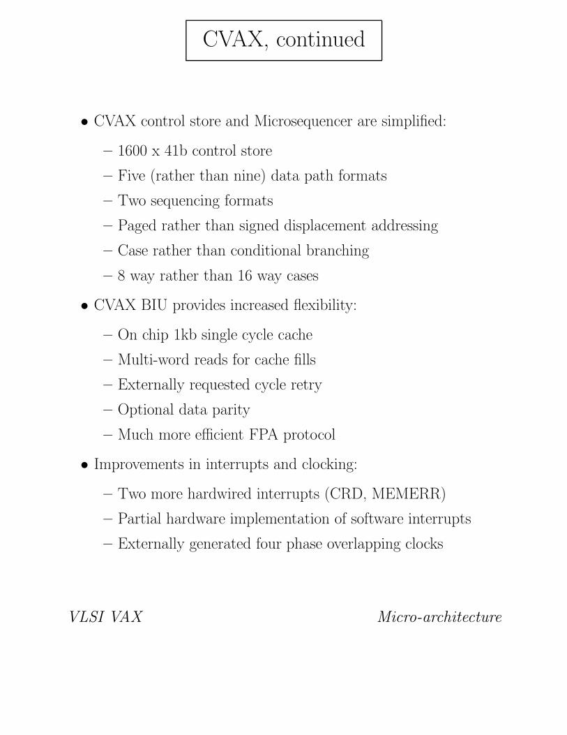
CVAX, continued
• CVAX control store and Microsequencer are simplified:
– 1600 x 41b control store
– Five (rather than nine) data path formats
– Two sequencing formats
– Paged rather than signed displacement addressing
– Case rather than conditional branching
– 8 way rather than 16 way cases
• CVAX BIU provides increased flexibility:
– On chip 1kb single cycle cache
– Multi-word reads for cache fills
– Externally requested cycle retry
– Optional data parity
– Much more efficient FPA protocol
• Improvements in interrupts and clocking:
– Two more hardwired interrupts (CRD, MEMERR)
– Partial hardware implementation of software interrupts
– Externally generated four phase overlapping clocks
VLSI VAX Micro-architecture

CVAX Decode Flow
EXAMPLE: ADDL3 R4, l^disp(R5), (R6)+
decoder next --> specifier decode
W[Sn] := GPR[Rn] ! Flow for specifier
! Sn = 0, Rn = 4
decoder next --> specifier decode (IDR loaded)
VA := GPR[Rn] + IDR ! Flow for specifier
W[Sn] := MEM(VA) ! Sn = 2, Rn = 5
decoder next --> specifier decode
VA,W[Sn]:= GPR[Rn] ! Flow for specifier
GPR[Rn]:= GPR[Rn] + 4 ! Sn = 4, Rn = 6
decoder next --> execution dispatch
W[0] := W[0] + W[2] ! Execution
MEM(VA):= W[0] ! End of instruction
VLSI VAX Micro-architecture

Rigel
• Third generation VLSI VAX single chip microprocessor:
– MicroVAX subset CPU (175 instructions) plus companion
floating point unit (70 instructions)
– CMOS-2 process (1.5u drawn, CMOS, double level metal)
– 325,000 transistors, tbd mils x tbd mils
– 30 ns - 40ns microcycle, 90ns - 120ns I/O cycle
– 64 entry TB, 2kb cache
– 1700 x 50b control store
• Performance goal is 6X - 8X current generation:
– 2X from technology improvements
– 3X from micro-architectural pipelining
– Remainder from improved memory subsystem
VLSI VAX Micro-architecture

Rigel
• Faster microcycle – technology:
– CMOS-2 process substantially faster than ZMOS (1.5ns rep-
resentative gate delay vs 3ns)
– Lower power permits fuller use of large devices for speed-
critical paths
• Faster microcycle – micro-pipelining:
– Fully folded micro-pipeline
– Register file writes through, thereby allowing writes under
reads with just one level of explicit bypass logic
– Micro-branch latency increases to three cycles
– Pipeline in I Box adds yet another cycle to macro-branch
latency
• Reduced TPI – better memory subsystem:
– Enlarged TB (64 entries) for reduced misses
– On chip single cycle cache (2kb, direct map, 8 byte block)
– Off chip three cycle cache (128kb, direct map, 16 byte fill
size, 64 byte block size)
– Multi-word read for all cache fills
– Multi-word writes for burst output situations
– Read and run pipeline
VLSI VAX Micro-architecture

Rigel, continued
• Rigel I Box is based on CVAX/ Nautilus rather than 780:
– I Box is an autonomous state machine which parses the in-
struction stream based on its own state data
– I Box parses all specifiers using one generic (parameterized)
set of specifier flows
– I Box and E Box are synchronized by a single directive, DE-
CODER NEXT
– Prefetch queue is 16 bytes (4 aligned longwords), allowing
retirement of up to 10 bytes per microcycle
– Instruction data register automatically loaded in all cases
• Rigel E Box implements fully folded micro-pipeline, plus read
pipelining:
– All registers have extra (write) port
– MD (working) registers have second write port plus valid bits
for synchronization
– Bypass around ALU/ shifter and through register file
– 8 extra T registers for per process stack pointers and memory
management length registers
– MD7 is separate register, SC and Q are again combined
– PSL is maintained in hardware
• Rigel M Box is simplified:
– 64 TB entries

– Not last used (NLU) replacement algorithm
– Length checks implemented in microcode rather than in
hardware
VLSI VAX Micro-architecture

Rigel, continued
• Rigel control store and Microsequencer are simplified:
– 1600 x 50b control store
– Four data path formats
– Two sequencing formats
– Paged rather than signed displacement addressing
– Case rather than conditional branching
– 8 way rather than 16 way cases
• BIU provides even more flexibility:
– On chip 2kb single cycle cache
– Multi-word reads for cache fills
– Multi-word writes for high output
– Externally requested cycle retry
– Mandatory data parity
– Much more efficient FPA protocol
• Improvements in interrupts and clocking:
– Two more hardwired interrupts (CRD, MEMERR)
– Full hardware implementation of software interrupts
– Externally generated four phase overlapping clocks
VLSI VAX Micro-architecture

Rigel Decode Flow
EXAMPLE: ADDL3 R4, l^disp(R5), (R6)+
decoder next --> specifier decode
MD[Sn] := GPR[Rn] ! Flow for specifier
! Sn = 0, Rn = 4
decoder next --> specifier decode (IDR loaded)
MD[Sn] := MEM(GPR[Rn]+IDR) ! Flow for specifier
! Sn = 2, Rn = 5
decoder next --> specifier decode
VA := GPR[Rn] ! Flow for specifier
GPR[Rn]:= GPR[Rn] + 4 ! Sn = 4, Rn = 6
decoder next --> execution dispatch
MEM(VA):= MD[0] + MD[2] ! Execution
VLSI VAX Micro-architecture

Summary
• The implementation of the VAX in VLSI has required some
adaptations and adjustments at the macro-architectural level.
• The four VLSI VAXen defined to date (MicroVAX, V-11, CVAX,
and Rigel) all follow the same (canonical) micro-architectural
model.
• The implementation process is complex, with much effort ex-
pended on architectural nits that have little or no performance
benefit.
• The constraints of the VAX architecture have limited attempts
at performance improvement to just three basic areas:
– Improved technology
– Microcycle pipelining
– Improved memory subsystem
• Despite the difficulties, the VLSI VAXen have proven both pop-
ular and competitive, and will form the basis of DEC’s low end
and mid range product offerings for years to come.
VLSI VAX Micro-architecture