vitalsbridge - laerdal medical
TRANSCRIPT

VitalsBridge
Directions for Use MODEL VB2.0 for US Government Customers
TM

VitalsBridge Directions for Use (for US Government Customers)
1 rev. B.10 PN 10229
Table of Contents Regulatory Information ..........................................................................................................2
Support .................................................................................................................................3
Warnings and Caution ............................................................................................................4
Requirements Checklists ........................................................................................................6
VitalsBridge Overview ............................................................................................................7
Powering the VitalsBridge ......................................................................................................8
External Power .................................................................................................................... 8
Internal Battery ................................................................................................................... 8
Internal Fan ......................................................................................................................... 8
Network Connections .............................................................................................................9
Overview ............................................................................................................................. 9
Installation of the VitalsBridge Software ............................................................................... 11
Cables, Tubing, and Regulator Setup/Configuration .............................................................. 14
Pulse Oximetry (SpO2) ....................................................................................................... 14
Configuration of a Compressed CO2 Source ..................................................................... 16
Capnography (Side-stream End Tidal CO2) ....................................................................... 19
Non-invasive Blood Pressure (NIBP) ................................................................................. 19
Invasive Blood Pressure (IBP)............................................................................................ 21
Temperature ..................................................................................................................... 22
Respiration Impedance via Electrocardiogram (ECG) ....................................................... 23
Running the VitalsBridge ...................................................................................................... 24
VitalsBridge Software Features ............................................................................................ 27
SpO2 Calibration ................................................................................................................ 27
Enabling CO2 Simulation ................................................................................................... 29
CO2 Calibration .................................................................................................................. 30
Zeroing the Invasive Blood Pressure(s) ............................................................................. 32
Pulmonary Artery Capillary Pressure and Invasive Blood Pressure Offsets ..................... 33
Network Configuration Tool Software .................................................................................. 34
VitalsBridge Frequently Asked Questions .............................................................................. 37

VitalsBridge Directions for Use (for US Government Customers)
2 rev. B.10 PN 10229
Regulatory Information
Use statement: The VitalsBridge is for use in the United States and Canada only.
Federal Communications Commission Statement: This device complies with part 15 Subpart B of the
FCC rules.
Caution: Only use cables supplied with the VitalsBridge and accessories approved for use
with the VitalsBridge. Changes or modifications not expressly approved by the party
responsible for compliance could void the user's authority to operate the equipment.
Disposal/Recycling: Recycle and dispose of in accordance with all governing requirements and
regulations. The VitalsBridge contains a Li-ion battery, which should be recycled.
The VitalsBridge instrumentation and its associated cables are latex free.
LATEX

VitalsBridge Directions for Use (for US Government Customers)
3 rev. B.10 PN 10229
Support
For technical assistance, contact your local Laerdal Technical Service Center.
Disclaimer
Use of the VitalsBridge to train personnel should be undertaken under supervision of suitably trained
medical personnel with an understanding of clinical monitoring, patient simulation educational
principles, and recognized medical protocols. As with all simulation training devices, there may be
approximations, variations, and inaccuracies in the information being presented.
Global Warranty
See the Laerdal Global Warranty, www.laerdal.com.
Manufacturer
The VitalsBridgeTM is made in the USA and is manufactured for Laerdal Medical AS by:
Dynasthetics LLC.
3487 W. 2100 S. #300
Salt Lake City, Utah, 84119
USA
VitalsBridge Directions for Use (for US Government Customers)
4 rev. B.10 PN 10229
Warnings and Caution Follow all cautions and warnings outlined in the SimMan 3G or SimMan Essential Directions for Use.
The VitalsBridge is intended solely for use during patient simulation. It is not a medical device.
Warning: Never connect the VitalsBridge to a patient.
Warning: Never connect the VitalsBridge to a Vital Signs monitor that is connected to a patient.
Warning: The VitalsBridge is not waterproof. Protect the VitalsBridge in damp conditions and
keep away from liquids.
Warning: The VitalsBridge contains a lithium ion battery, which if damaged, could cause risk of
fire or explosion.
Compressed Gases and Regulators
Use only sources of compressed CO2 with the VitalsBridge. Adequate training and expertise is required
to work with compressed gases.
The VitalsBridge is supplied with a portable CO2 regulator that uses cartridges of highly pressurized CO2
gas. Take care when handling these cartridges as they pose a potential risk of injury if used improperly.
Cartridges should be stored and operated at temperatures below 120o F (49o C) and punctures should be
prevented. They should not be heated. They should not be used or stored ate temperatures above 120o
F or 49o C. Do not inhale the CO2 gas.
Warning: Do not use compressed oxygen (fire hazard) or any other flammable substance with or
near the VitalsBridge.
Warning: CO2 cartridges may become extremely cold when discharging. Protect eyes and hands
when installing and handling CO2handling CO2 cartridges.
Warning: Mishandled CO2 cartridges may become a projectile.
Caution: CO2 cartridges may not be transported by air.
VitalsBridge Directions for Use (for US Government Customers)
5 rev. B.10 PN 10229
Defibrillation Hazards:
During defibrillation the defibrillator and VitalsBridge may present a shock hazard. All standard safety
precautions must be taken when using a defibrillator with the SimMan 3G/Essential and VitalsBridge.
The respiration cable connector on the manikin is designed exclusively for respiration monitoring via
ECG impedance signals.
Warning: Defibrillation on the ECG connectors will damage the internal electronics of the
VitalsBridge and may cause personal injury.
Warning: Never connect any cables from the VitalsBridge to the designated defibrillator
connectors on the SimMan 3G/Essential manikin.

VitalsBridge Directions for Use (for US Government Customers)
6 rev. B.10 PN 10229
Requirements Checklists
Checklist of Included Cables and Accessories: Please verify the following has been included in your shipment; all of the following cables and
accessories are REQUIRED to properly operate the VitalsBridge. If you are missing any of these items, or
they are damaged, please contact Laerdal for replacements.
1. VitalsBridge power supply, 24V, with wall plug.
2. CO2 Regulator with mounting bracket.
3. Non-Invasive blood pressure tubing (connects from VitalsBridge to blood pressure cuff).
4. Invasive blood pressure transducer cable (3 RJ11 cables, connects from VitalsBridge to monitor’s
blood pressure cable(s)).
5. Temperature transducer cable (2, connects from VitalsBridge to monitor’s temperature
cable(s)).
6. Respiration via ECG cable (connects from VitalsBridge to manikin).
7. SpO2 Extension Cable (connects from VitalsBridge to manikin).
8. These directions for use.
Checklist of Required Cables and Accessories Not Included (Must be Purchased
Separately from Laerdal) 1. Non-Invasive Blood Pressure Cuff Kit.
2. Invasive Blood Pressure Monitor Cables.
Computer and Software Requirements 1. Windows operating system.
2. LLEAP or legacy SimMan 3G Instructor Application software.
3. Ethernet (LAN) or wireless (WLAN) communication capability.
4. VitalsBridge software (may be downloaded from laerdal.com).
Additional Requirements 1. VitalsBridge instrumentation.
2. SimMan 3G or SimMan Essential manikin, updated with SpO2-compatible hand and ECG-
respiration kit.
3. Commercially available vital signs monitor.
4. AC power source (i.e. a wall outlet).
5. Source of compressed CO2 (either a disposable cartridge for use with included regulator, or
another external source).

VitalsBridge Directions for Use (for US Government Customers)
7 rev. B.10 PN 10229
VitalsBridge™ Overview The VitalsBridge consists of a device that allows vital signs from the SimMan 3G or SimMan Essential to
be presented on a clinical vital signs monitor. It is intended to increase the fidelity of simulation for
users where they may view, interact, and control a vital signs monitor that is used in their clinical
practice. The VitalsBridge presents opportunities for high-fidelity simulations that involve critical care,
training and education on clinical monitoring, patient information systems testing, just to name a few.
The VitalsBridge is designed to function with commercially available vital signs monitors. It presents the
following vital signs on a clinical monitor: heart rate, respiration via Electrocardiogram (ECG)
impedance, plethysmography waveform, SpO2, capnography waveform, end-tidal CO2, non-invasive and
invasive blood pressure (arterial, central venous, pulmonary artery), and temperature. Vital signs cables
are usually connected to sensors attached to the patient. With the VitalsBridge, some of these cables
attach to the patient, and some are connected to the VitalsBridge device. Connectors for the respiration
via ECG impedance and SpO2 have been pre-installed on the SimMan 3G/Essential manikin.
The VitalsBridge converts the digitized vital signs waveforms and numbers of the SimMan 3G/Essential
into signals that are compatible with a vital signs monitor. Compressed CO2 gas is used for non-invasive
blood pressure and capnography to generate the signal. The vital signs created by the VitalsBridge are
controlled using the SimMan3G Instructor Application. Additional software is used to communicate vital
signs information between the SimMan 3G/Essential and the VitalsBridge.

VitalsBridge Directions for Use (for US Government Customers)
8 rev. B.10 PN 10229
Powering the VitalsBridge™
External Power To power the VitalsBridge via wall power, simply connect the external power adapter and plug into any
standard wall outlet.
Caution: Use only the included 24V power supply. Using an incorrect power supply may damage
the VitalsBridge and void the warranty.
Internal Battery The VitalsBridge contains an internal, non-replaceable Lithium-Ion battery to allow for unplugged
operation of the unit. When fully charged, this will allow for at least 3 hours of use. To charge the
battery, connect the external power supply. The power supply will charge a fully depleted battery in 6-
12 hours. When the unit is switched on, the battery indicator on the top panel will flash when there is
less than 15% of battery life remaining; if you need to continue using the VitalsBridge, connect the
external power.
Internal Fan The VitalsBridge contains an internal fan to keep the battery cool while charging and discharging during
use. The fan will be active under the following conditions:
1. Any time the VitalsBridge is connected to the external power supply.
2. When the VitalsBridge is switched on and not connected to the external power supply.
VitalsBridge Directions for Use (for US Government Customers)
9 rev. B.10 PN 10229
Network Connections
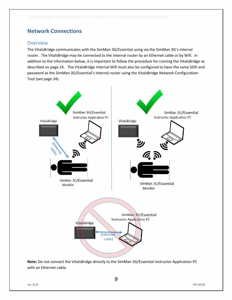
Overview The VitalsBridge communicates with the SimMan 3G/Essential using via the SimMan 3G’s internal
router. The VitalsBridge may be connected to the internal router by an Ethernet cable or by Wifi. In
addition to the information below, it is important to follow the procedure for running the VitalsBridge as
described on page 24. The VitalsBridge internal Wifi must also be configured to have the same SSID and
password as the SimMan 3G/Essential’s internal router using the VitalsBridge Network Configuration
Tool (see page 34).
Note: Do not connect the VitalsBridge directly to the SimMan 3G/Essential Instructor Application PC
with an Ethernet cable.
/Essential /Essential
/Essential
/Essential SimMan 3G/Essential

VitalsBridge Directions for Use (for US Government Customers)
10 rev. B.10 PN 10229
When connecting the VitalsBridge to the SimMan 3G/Essential manikin using an Ethernet cable, ensure
the cable is functional and is securely connected to the Ethernet ports of the VitalsBridge and the
manikin. The top of the VitalsBridge indicates when it has established an Ethernet or Wifi connection
with the manikin’s internal router.
(Ethernet Connection)
(Wifi Connection)

VitalsBridge Directions for Use (for US Government Customers)
11 rev. B.10 PN 10229
Installation of the VitalsBridge Software The VitalsBridge software may be installed on a PC that is able to establish a network connection with
the SimMan 3G/Essential manikin or to an instance of the virtual manikin. The instructor application PC
is recommended for installation of the VitalsBridge software. Download the appropriate VitalsBridge
installation software from www.laerdal.com. If necessary, copy the software to the computer on which
it will be installed. Navigate to the installation software file and open in. Follow the on-screen
installation instructions. Upon successful installation, a VitalsBridge icon will be created on the PC's
desktop. Restart the computer if the installation software does not prompt for a reboot.
Note: Choose the appropriate VitalsBridge installation software carefully. There may be specific
installation software that is compatible with the version of software running on the SimMan
3G/Essential (e.g., LLEAP versus legacy versions of SimMan 3G software), or the particular version of
LLEAP.

VitalsBridge Directions for Use (for US Government Customers)
12 rev. B.10 PN 10229

VitalsBridge Directions for Use (for US Government Customers)
13 rev. B.10 PN 10229
Windows Network Settings Communication between the VitalsBridge instrumentation and the VitalsBridge software occurs over the
UDP network protocol on port 14996. The installation software attempts to allow access of this port
through the Windows Firewall on both the public and private profiles. For older versions of Windows
(e.g., Windows Vista), custom firewall configurations, and custom network settings, consult your IT
support and/or Windows help on how to let communication occur properly on this port.

VitalsBridge Directions for Use (for US Government Customers)
14 rev. B.10 PN 10229
Cables, Tubing, and Compressed CO2 Setup/Configuration This section will describe how to connect the cables and tubing between the VitalsBridge, the SimMan
3G/Essential, and the patient monitor. Please note that invasive blood pressure and temperature
patient monitoring cables, specific to the brand and model of patient monitor being used with the
VitalsBridge may be purchased from Laerdal. Note that your monitor will also require a type of non-
invasive blood pressure cuff, either a 1-tube or 2-tube design, depending on the brand and model of
patient monitor being used. In addition, the patient monitor’s SpO2 sensor probe and cable is used with
the VitalsBridge. Please consult the patient monitor documentation for more information regarding
temperature cables, invasive/non-invasive blood pressure cables, and SpO2 sensor probes and cables.
Pulse Oximetry (SpO2) Pulse oximetry, or SpO2, is used to determine the oxygen saturation of a patient’s blood. It also will
provide a pulse measurement. SpO2 simulation by the VitalsBridge uses special circuitry inside the
manikin’s index finger of the right hand, which provides expected light levels of light to the monitor’s
SpO2 probe according to the SpO2 value set in the SimMan 3G’s Instructor Application.
Note: The SpO2 circuitry in the manikin’s hand must be located at the tip of the index finger. If there is
empty space between the manikin’s fingertip skin and the sensors, the skin will need to be adjusted for
a tight fit. Gently, but firmly, push the manikin skin further down so that it is. Contact Laerdal if
additional assistance is needed.
When placing the patient monitor’s SpO2 sensor probe, ensure its orientation is correct. The probe’s
source light should be placed over the manikin’s fingernail. Note: SpO2 will not function properly in
other orientations of probe placement. Below is an example depicting proper placement of a Nellcor
non-disposable probe on the manikin’s right index finger.
Top of probe (source light)
Bottom of probe (source
detector)
Manikin’s fingernail
VitalsBridge Directions for Use (for US Government Customers)
15 rev. B.10 PN 10229
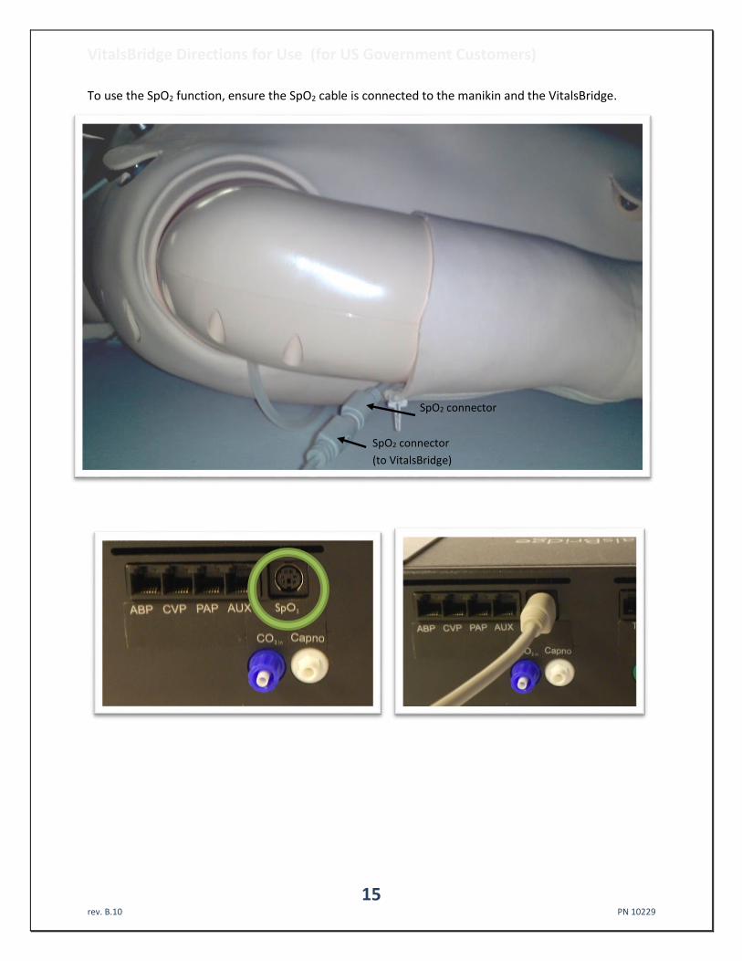
To use the SpO2 function, ensure the SpO2 cable is connected to the manikin and the VitalsBridge.
SpO2 connector
(to VitalsBridge)
SpO2 connector
(to sensor in Manikin's finger)

VitalsBridge Directions for Use (for US Government Customers)
16 rev. B.10 PN 10229
Configuration of a Compressed CO2 Source For capnography and non-invasive blood pressure (NIBP) simulation, a source of compressed CO2
regulated to 20-30 PSI is required. A portable CO2 regulator that uses cartridges of compressed CO2 is
provided with the VitalsBridge. Alternatively, compressed CO2 from another external source may be
available at your facility (wall source, a tank, etc). Consult your facility's engineering regarding external
CO2 sources and the appropriate regulators and adapters for correct and safe connection.
Using the Portable CO2 Regulator: The portable CO2 regulator is mounted to the side opposite the
switch and uses a 16g threaded disposable cartridge of compressed CO2. The regulator may be
detached by lifting the regulator up out of the slot that is on the side of the VitalsBridge. The regulator
has a luer lock fitting that will connect into the VitalsBridge, and regulator knob to control the flow of
gas. The regulator should be turned to the off position when it is not connected to the VitalsBridge via
the luer connection. Only turn the regulator on when a tight secure connection to the VitalsBridge has
been verified.
Note: Carefully verify the regulator that you are using. Some regulators supplied with the VitalsBridge
have a maximum pressure of 30 PSI on the gauge, while other regulators have a higher maximum
pressure reading on the gauge (e.g., 140 PSI). Either are acceptable, where the regulated pressure will
be set to 20-30 PSI as per the instructions below.
Caution: The regulator must be kept upright when the CO2 cylinder is attached. Do no tilt the
regulator more than 30 degrees from vertical when in use. The CO2 cylinder is pressurized. Sudden
release of pressure may cause injury. Turn regulator to OFF when not in use.

VitalsBridge Directions for Use (for US Government Customers)
17 rev. B.10 PN 10229
Installing a CO2 Cartridge (see images labeled (2) – (7) that correspond with the steps below):
1. Temporarily remove the regulator from its bracket on the VitalsBridge instrumentation. 2. Adjust the regulator knob to the “OFF” position by rotating it counterclockwise. 3. Orient the VitalsBridge so the threaded connection on the regulator can be seen. Hold the
regulator in one hand, align the cartridge under the housing, and quickly turn it clockwise into the regulator. Do not stop until tight. Do not over tighten; the cartridge only needs to be hand-tight. It is normal for a small amount of CO2 to leak out during cartridge installation.
4. Attach the blue tubing to the blue luer lock (CO2 in) on the front of the VitalsBridge and verify a secure connection.
5. Replace the regulator back on the bracket that is attached to the VitalsBridge instrumentation. 6. If the regulator supplied with the VitalsBridge has a maximum pressure of 30 PSI on the gauge,
then SLOWLY turn regulator knob clockwise to the “HI” position, usually set at or just above 20 PSI. Note: it is acceptable if the gauge reading is in the red area.
For regulators that have a maximum pressure on the gauge that is greater 30 PSI (e.g., 140 PSI), then SLOWLY turn the regulator knob clockwise until the pressure on the gauge reads 30 PSI. Do not set the regulator to a reading higher than 30 PSI.
7. The regulator is now set at the maximum regulated pressure.
(2) (3) (4)
(4)

VitalsBridge Directions for Use (for US Government Customers)
18 rev. B.10 PN 10229
Caution: Ensure CO2 has been fully released prior to disposing of the cartridge. This may be
accomplished by: (i) turning the regulator to “OFF”, (ii) detaching the female luer fitting from
the blue luer lock ring on the VitalsBridge, (iii) slowly turning the regulator knob clockwise
(towards “HI”), and (iv) allowing the remaining compressed CO2 gas to expel in a controlled
manner. The CO2 cartridge may be very cold. Point the outlet of the cartridge away from
yourself and others. Wear eye protection. Ensure that the knob is turned to the off position
before a new cartridge is installed.
Caution: When not in use turn the CO2 to the off position and disconnect the CO2 line from the
VitalsBridge.
Warning: CO2 cartridges may become extremely cold when discharging. Protect eyes and hands
when installing and handling CO2 handling CO2 cartridges.
Warning: Mishandled CO2 cartridges may become a projectile.
Caution: CO2 cartridges may not be transported by air.
(5) (6) (7)

VitalsBridge Directions for Use (for US Government Customers)
19 rev. B.10 PN 10229
Capnography (Side-stream End Tidal CO2) The VitalsBridge is configured for simulating side-stream capnography. Capnography is the
measurement of patients’ exhalation of CO2. The VitalsBridge utilizes an air pump and the compressed
CO2 source to provide a mixture composed of the correct amount of air and CO2 to simulate the fraction
of CO2 exhaled over each breath by a patient. To use the capnography function, first ensure that your
patient monitor supports capnography measurement. If it does, connect its capnography line to the
white fitting on the VitalsBridge.
Non-invasive Blood Pressure (NIBP) The VitalsBridge is capable of simulating non-invasive blood pressure by simulating the pulsing of the
artery. It uses two tubing connections; the red connection provides the pulse, and the green connection
measures the pressure in the cuff. The
VitalsBridge automatically detects and
controls pulsing during a non-invasive blood
pressure reading by the patient monitor. A
specially configured blood pressure cuff is
used with the VitalsBridge. Some patient
monitors require a 1-tube cuff, others a 2-
tube. Please consult the patient monitor’s
configuration and associated
documentation to determine which cuff is
required.
To side-stream CO2
connection on vital signs
monitor.

VitalsBridge Directions for Use (for US Government Customers)
20 rev. B.10 PN 10229
The tubing connections to the VitalsBridge are color coded:
A 1-tube blood pressure cuff is configured as follows:
To VitalsBridge
NIBP tubing
To NIBP Tubing connection on the
patient monitor

VitalsBridge Directions for Use (for US Government Customers)
21 rev. B.10 PN 10229
A 2-tube cuff is configured as follows.
The tubing connection from the NIBP cuff to the patient monitor will need configuration, depending on
the style of connector used with the patient monitor’s NIBP tubing. A variety of connectors have been
included for appropriate fitting(s) to be placed at the end of the cuff tubing that connects with the
patient monitor NIBP tubing.
Caution: The NIBP cuffs have been modified to function with the VitalsBridge with the
VitalsBridge, and are not for clinical use.
Invasive Blood Pressure (IBP) The VitalsBridge is able to simultaneously simulate up to 3 different invasive blood pressure waveforms.
These include arterial blood pressure (ABP), central Venous pressure (CVP), pulmonary artery pressure
(PAP) or pulmonary capillary wedge pressure (PCWP). The VitalsBridge simulates the transducer output
signal for each invasive blood pressure and utilizes an RJ-11 cable to connect from the VitalsBridge to
the patient monitor’s IBP cable. Note: contact Laerdal for assistance with purchasing a VitalsBridge-
compatible invasive blood pressure monitoring cable (i.e., the cable that connects from the patient
monitor to the VitalsBridge RJ-11 cable).
To VitalsBridge
NIBP Tubing
To Patient
Monitor’s NIBP
Tubing
connection

VitalsBridge Directions for Use (for US Government Customers)
22 rev. B.10 PN 10229
When using IBP, all waveforms are not required to for the VitalsBridge to function. Unused IBP ports on
the VitalsBridge may be left unconnected.
Temperature The VitalsBridge simulates the output of YSI 400 compatible temperature transducers. The temperature
cable is a short white cable that consists of a short RJ-11 connector on one end, which connects to the
VitalsBridge. The other end of the cable is a transducer-style connector, which connects to the
temperature patient monitor cable. Two temperature cables are supplied with the VitalsBridge. T1
simulates the temperature in the blood, and T2 simulates Tperi.

VitalsBridge Directions for Use (for US Government Customers)
23 rev. B.10 PN 10229
Respiration Impedance via Electrocardiogram (ECG) This connection is utilized with a cable plugged into a connector located on the manikin’s neck.
The other end of the cable plugs into the VitalsBridge.
Once connected, the patient monitor will display the respiration rate and ECG information. Note: a three
lead ECG is recommended with the patient monitor and the SimMan 3G/Essential for respiration
impedance simulation.

VitalsBridge Directions for Use (for US Government Customers)
24 rev. B.10 PN 10229
Running the VitalsBridge™
Because the VitalsBridge requires a network connection with the SimMan 3G/Essential’s internal router,
there is a specific sequence for initializing and running the VitalsBridge. Assuming that both the
VitalsBridge and SimMan 3G/Essential are turned off, the summary of the steps are as follows:
1. Power on the manikin and wait until manikin is breathing
2. Power on the SimMan 3G/Essential instructor PC
3. Run the Instructor Application software (either through the legacy SimMan 3G software or
LLEAP)
4. Power on the VitalsBridge instrumentation, wait for network connection.
5. Run the VitalsBridge software
Step 1: Power on the SimMan 3G/Essential manikin and wait until manikin is breathing. Refer to the
SimMan 3G/Essential’s directions for use on how to power on the manikin.
Step 2: Power on the SimMan 3G/Essential instructor PC. Refer to the SimMan 3G/Essential’s directions
for use on how to appropriately power on the Instructor PC.
Step 3: Run the Instructor Application software. Refer to the SimMan 3G/Essential’s directions for use on
how to appropriately run the SimMan 3G Instructor Application software.
Step 4: Power on the VitalsBridge instrumentation, wait for network connection. Use the toggle switch,
located on the side panel, to power VitalsBridge on or off. Once powered on, the VitalsBridge takes
approximately 6-15 seconds to initialize and attempt to connect to the manikin’s internal router.
Check the status indicator lights on top of the VitalsBridge instrumentation to determine power and
connectivity.

VitalsBridge Directions for Use (for US Government Customers)
25 rev. B.10 PN 10229
The VitalsBridge instrumentation has 4 LEDS: Power, battery/charge, WLAN and LAN.
- Power indicator:
o no light: switched off, or switched on and no power to the VitalsBridge o solid: switched on and power available to the VitalsBridge
- Battery/charge indicator:
o no light: VitalsBridge is not running o solid: VitalsBridge is on, battery charge > 15% o flashing every 1 second: unit is running on low battery charge < 15%
- WLAN or LAN:
o no light: not connected to router o solid: VitalsBridge connected to the manikin’s internal router o flashing ~ 1x/second: VitalsBridge connected to router and is trying to associate a
connection o flashing on/off frequently: VitalsBridge receiving/sending from/to a SimMan
3G/Essential
Step 5: Run the VitalsBridge software: Double click on the VitalsBridge icon, labeled VitalsBridge,
located on the computer's desktop.

VitalsBridge Directions for Use (for US Government Customers)
26 rev. B.10 PN 10229
Alternatively, the software may be located by searching for “VitalsBridge” using the Windows search
function (i.e., by pressing the button in Windows 7 and typing in the search dialog or by pressing
+S in Windows 8). The first window that is shown allows association between a running SimMan
3G/Essential manikin and a VitalsBridge device. Click on the desired manikin and VitalsBridge device and
press the Connect button.
It is also possible to manually enter the manikin and VitalsBridge connection information: the manikin
name or ip address and the VitalsBridge serial ID and ip address.
Upon successful association with the two devices, the main VitalsBridge user interface is shown. A
summary of the vital signs that are being sent from the SimMan 3G/Essential to the VitalsBridge is
shown.

VitalsBridge Directions for Use (for US Government Customers)
27 rev. B.10 PN 10229
VitalsBridgeTM Software Features
The VitalsBridge software allows the user to monitor connectivity between the VitalsBridge and the
SimMan 3G/Essential, calibration of SpO2 and CO2 signals, and configuration of other settings.
Additionally, if some waveforms are unneeded for the simulation (e.g., PAP/PCWP, CVP, CO2), uncheck
the box next to the vital sign's label. CO2 is off by default, check to enable capnography. The Calibrate
tab provides functionality for calibrating SpO2 and CO2 and selecting default or previously stored
calibrations.
SpO2 Calibration The VitalsBridge is pre-calibrated with factory settings for a Nellcor standard probe. If the SpO2 value
set on the Instructor Application significantly deviates from the value on the vitals sign monitor, then it
is possible to use your own calibration. To perform a new calibration, first ensure the probe is properly
set and aligned on the manikin’s right index finger (page 14), then select “update“ next to the SpO2 label
located in the “Calibrate” tab. Then select “(New Calibration)”.

VitalsBridge Directions for Use (for US Government Customers)
28 rev. B.10 PN 10229
Enter the name of the custom calibration.
The first portion of the calibration procedure involves scaling the height of the plethysmograph (pleth)
waveform. Usually, a scale factor of 4 is best, but may be increased or decreased in size if necessary. If
you wish to use a different scaling factor, adjust the scaling factor until a pleth waveform of adequate
size is viewed on the vital signs monitor, and there is also a SpO2 reading shown on the monitor.
For each calibration point, observe the target SpO2 value in the calibration window in the software.
Slowly move the indicator to the left to decrease the SpO2 value observed on the vital signs monitor or
to the right to increase the SpO2 value on the vital signs monitor. It is recommended to use the left and
right arrow keys on the keyboard to make adjustments. Observe the vital signs monitor for changes in
the SpO2 reading. Adjust the indicator until the target SpO2 in the dialog window in the VitalsBridge

VitalsBridge Directions for Use (for US Government Customers)
29 rev. B.10 PN 10229
software matches or nearly matches the SpO2 reading on the patient vital signs monitor. Then, click the
submit button to proceed to the next calibration point. Note: ignore the SpO2 reading that is shown in
the Instructor Application during SpO2 calibration.
Some vital signs monitors will filter and average the SpO2 value, and there may be a several second
delay before the reading changes to indicator movements. Repeat for all calibration points. Once
completed, the calibration data will automatically be stored and retrieved on the VitalsBridge.
Unused custom calibrations may be removed by highlighting the desired calibration to remove and
clicking the remove button.
Enabling CO2 Simulation Capnography requires use of a pump internal to the VitalsBridge. The pump is active during
capnography simulation. Because the pump consumes additional power and adds a moderate level of
noise, CO2 may be disabled. In the VitalsBridge software uncheck the CO2 option. Note, CO2 is
unchecked by default.

VitalsBridge Directions for Use (for US Government Customers)
30 rev. B.10 PN 10229
CO2 Calibration Calibration may be needed if the end-tidal CO2 reading on the patient vital signs monitor does not
properly match the CO2 waveform on the Instructor Application. From the “Calibrate” tab on the
VitalsBridge software, select “(Update)” next to the CO2 label. Select a “(New Calibration)”.
Enter the name of the custom calibration.
For each calibration point, observe the target etCO2 value in the CO2 Calibration window. Slowly move
the indicator to adjust the flow up or down until the end-tidal CO2 reading on the patient vital signs
monitor equals the target end-tidal CO2 reading.

VitalsBridge Directions for Use (for US Government Customers)
31 rev. B.10 PN 10229
Note that some vital signs monitors filter and average the end tidal CO2 value, and there may be a
several second delay for the reading to change. Additionally, small CO2 set values may be difficult to
read on the monitor. A useful feature, available in some patient vital signs monitors, is to "freeze" the
waveform and investigate it more closely (refer to the vital signs monitor documentation for additional
information).
Repeat for all calibration points. Once completed, the calibration data will automatically be
stored/retrieved on the VitalsBridge.
VitalsBridge Directions for Use (for US Government Customers)
32 rev. B.10 PN 10229
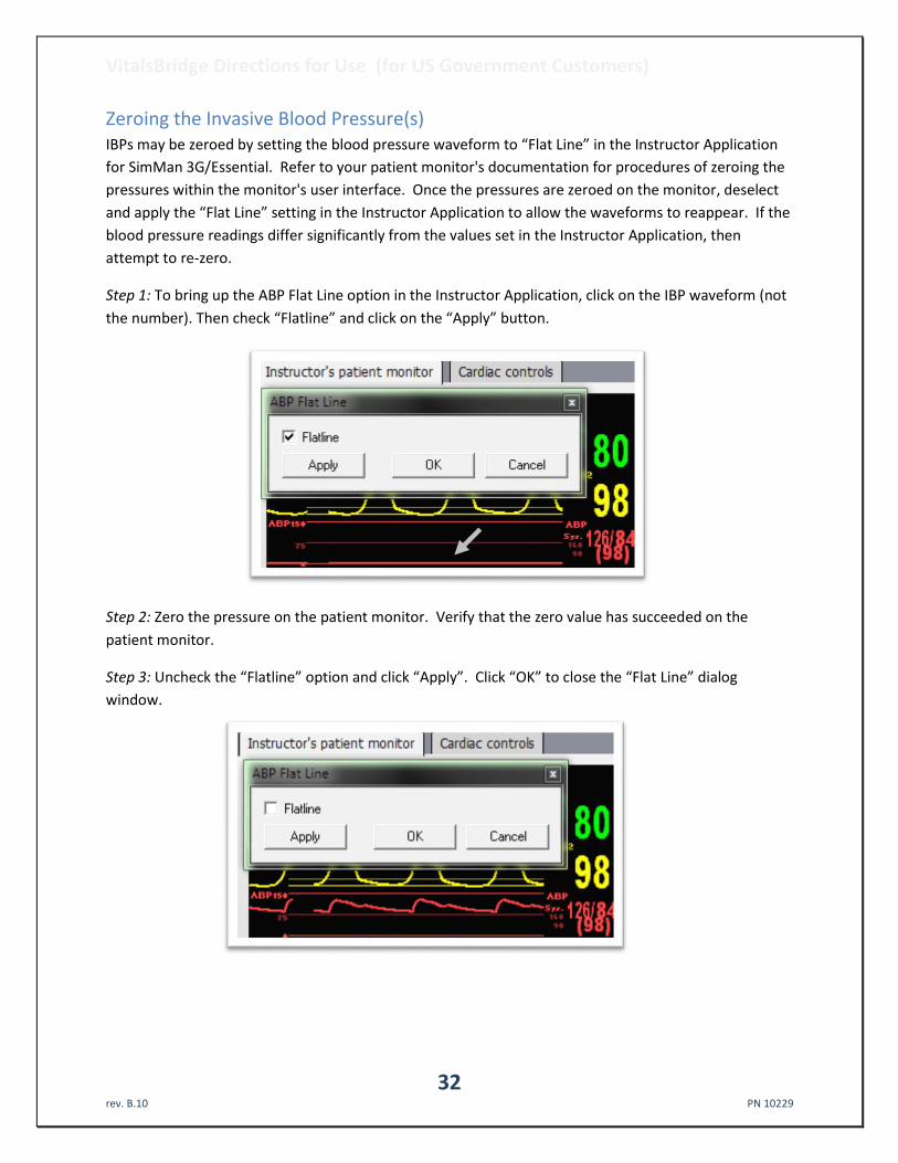
Zeroing the Invasive Blood Pressure(s) IBPs may be zeroed by setting the blood pressure waveform to “Flat Line” in the Instructor Application
for SimMan 3G/Essential. Refer to your patient monitor's documentation for procedures of zeroing the
pressures within the monitor's user interface. Once the pressures are zeroed on the monitor, deselect
and apply the “Flat Line” setting in the Instructor Application to allow the waveforms to reappear. If the
blood pressure readings differ significantly from the values set in the Instructor Application, then
attempt to re-zero.
Step 1: To bring up the ABP Flat Line option in the Instructor Application, click on the IBP waveform (not
the number). Then check “Flatline” and click on the “Apply” button.
Step 2: Zero the pressure on the patient monitor. Verify that the zero value has succeeded on the
patient monitor.
Step 3: Uncheck the “Flatline” option and click “Apply”. Click “OK” to close the “Flat Line” dialog
window.

VitalsBridge Directions for Use (for US Government Customers)
33 rev. B.10 PN 10229
Pulmonary Capillary Wedge Pressure Simulation Simulation of wedging a small pulmonary artery by inflating a balloon to measure the pulmonary
capillary wedge pressure (PCWP) is accomplished by checking the PCWP checkbox. This will send a
PCWP waveform from the VitalsBridge to the vital signs monitor using the PAP connection. Note: the
Instructor Application does not show the pulmonary capillary wedge pressure waveform; however, one
may access and change the PCWP value by clicking on the PAP numeric value in the Instructor
Application.
Invasive Blood Pressure Offsets An offset to each of the invasive blood pressures may be included, to attain additional accuracy with
invasive blood pressure readings on the vital signs monitor. Adjust the up/down arrows to
increase/decrease the offset of the BP waveform by 1 mmHg. When the IPB offset is unchecked in the
Device menu, no offset will be delivered to the signal.

VitalsBridge Directions for Use (for US Government Customers)
34 rev. B.10 PN 10229
Network Configuration Tool After installing the VitalsBridge software, a shortcut to the VitalsBridge Network Configuration Tool
should be located on the PC’s desktop. Alternatively, the software may be located by searching for
“Network Configuration Tool for VitalsBridge” using the Windows search function (i.e., by pressing the
button in Windows 7 and typing in the search dialog or by pressing +S in Windows 8). Perform
the following steps to set up your VitalsBridge to connect wirelessly to the SimMan 3G/Essential:
1. Identify the SSID (i.e., Wifi name) of the manikin’s internal router. This may be obtained by
inspecting the Network and Sharing Center when the SimMan 3G/Essential is connected and
running.
2. Exit all simulation programs (e.g., Instructor Application, LLEAP, etc).
3. Ensure both the manikin and the VitalsBridge are completely OFF.
4. Turn on the SimMan 3G/Essential; allow to initialize completely (breathing and blinking).
5. Power on the instructor PC, and ensure that it is connected to the manikin’s router via Wifi
(consult the SimMan 3G/Essential directions for use on information specific to this task).
6. Connect the VitalsBridge to the manikin via Ethernet cable.
7. Power on the VitalsBridge.
8. Wait approximately 5-30 seconds. Verify network connection indicator is lit up on top of the
box.
9. Open the VitalsBridge Network Configuration Tool. Double click on the Network Configuration
Tool shortcut icon on the PC’s desktop, and a selection window will appear.
10. Wait until the white box is appears with the VitalsBridge that is connected to the manikin. Note:
this usually takes a few seconds but may take as long as 30 seconds.
11. Select the VitalsBridge ID and click the “Connect” button.
12. After clicking on connect, the Network Configuration Tool window will appear.

VitalsBridge Directions for Use (for US Government Customers)
35 rev. B.10 PN 10229
13. Input the SSID (i.e., the name of the network) and password that is set for the manikin’s internal
router. Click the “Submit” button.
14. The Network Configuration Tool will configure the VitalsBridge to connect to the manikin’s
router wirelessly. Configuration takes approximately 1 minute. Do not power off the
VitalsBridge during this process.
15. The process is complete when the Network Configuration Tool dialog box reads “Power Cycle
VitalsBridge before attempting to connect via Wi-Fi”.
16. Turn off VitalsBridge.
17. Close Network Configuration Tool.
Your VitalsBridge is now set up to connect wirelessly.
VitalsBridge Network Configuration Using an External LAN Consult your network administrator for assistance configuring the VitalsBridge on an external LAN.
Using an Ethernet cable, connect the VitalsBridge to a LAN where the PC is located. Note: the local area
network must have UDP multicasting installed.

VitalsBridge Directions for Use (for US Government Customers)
36 rev. B.10 PN 10229
LAN Manual Connection For a manual LAN, uncheck the “Use DHCP” box in the Network Configuration Tool window, and check
the “Assign Manually” box. You may then input the IP, Gateway, and Subnet manually. Note: a
manually assigned LAN ip address is not recommended.

VitalsBridge Directions for Use (for US Government Customers)
37 rev. B.10 PN 10229
VitalsBridge Frequently Asked Questions
General Use and Connectivity Q: Who do I contact for customer support? A: In the US, phone: 877-LAERDAL (523-7325), email: [email protected] Q: Is my monitor is compatible with the VitalsBridge? A: There are many different brands and thousands of different configurations of vital signs monitors.
The VitalsBridge is compatible with most brands and models. The VitalsBridge is compatible with side-stream capnography technology (not mainstream). The VitalsBridge requires some specific cables and configuration for a vital signs monitor’s non-invasive blood pressure cuff, SpO2, invasive blood pressure, and temperature. Consult your Laerdal representative to purchase VitalsBridge compatible patient monitor cables.
Q: Is the VitalsBridge compatible with SimMan 3G/Essential manikins running the LLEAP software? A: Yes, the VitalsBridge is LLEAP compatible. However, when installing the VitalsBridge software, ensure
that the correct version is chosen (i.e., choose the LLEAP compatible installer if running with LLEAP). Q: How long will the VitalsBridge run on a fully charged battery? A: Typical running times are 2.5 to 4+ hours, depending on use and whether capnography simulation is
turned on in the VitalsBridge software. Q: What is the recommended sequence for starting the VitalsBridge? A: If you have been running the manikin for more than 30 minutes prior to starting the VitalsBridge, it is
recommended that you exit the Instructor Application software, and power off the manikin. Power on the manikin, wait for the manikin to start breathing (chest rise and fall), start the Instructor Application software, power on the VitalsBridge, wait for a network connection between the VitalsBridge and the SimMan 3G/Essential manikin, and start the VitalsBridge software.
Q: The VitalsBridge software shows that the VitalsBridge initially connects, but after 10-20 seconds, it
stops. What is wrong? A: The manikin server may have problems and is unable to send waveforms properly to the VitalsBridge.
This is particularly true when using the VitalsBridge with legacy versions of the Instructor Application (i.e., SimMan 3G manikins not running LLEAP). To fix: exit the VitalsBridge software and the Instructor Application, power off the manikin, power off the VitalsBridge, power on the manikin, wait for the manikin to start breathing (chest rise and fall), power on the VitalsBridge, start the Instructor Application software, start the VitalsBridge software. This issue usually happens after the manikin has been running for more than 1 hour and you are re-attempting to connect the VitalsBridge.
SpO2 Q: Is the VitalsBridge compatible with disposable SpO2 probes? A: It is possible to use disposable Nellcor SpO2 sensors (i.e., sticker-style sensors), but it is not
recommended. It is recommended that the Nellcor or Nellcor-Oximax non-disposable finger-clip style probes are used. The manikin’s hand geometry does not provide an optimal fit for the disposable style of SpO2 sensors; however, they can usually be made to work with careful placement.

VitalsBridge Directions for Use (for US Government Customers)
38 rev. B.10 PN 10229
Q: Is the VitalsBridge compatible with the Philips flexible finger-cot probe (M1191A) or Philips finger-clip style probe (M1196A)?
A: It is possible to use these style SpO2 sensors, but it is not recommended. Performance is best when using a Nellcor compatible probe.
Q: I am not getting a SpO2 waveform reading. What is wrong? A: First, check that there is no loose skin at the tip of the index finger on the manikin’s right hand. By
pinching the fingertip, you should be able to feel something solid underneath. If not, use your hands to slowly but firmly work the skin on the finger towards the hand until all excess space at the fingertip is gone. You may have to push down the skin of the other fingers as well to ensure the entire hand skin is properly placed on the manikin’s hand. Second, check proper placement of a non-disposable finger-clip style probe: there should be no gap between the tip of the finger and the top housing of the probe. Remove and replace the probe if needed. Check proper function of the SpO2 probe and monitor by placing it on a live person’s finger.
Non-invasive Blood Pressure Q: I am not getting a reading from my non-invasive blood pressure monitor. What should I check? A: First check that the cable from the monitor is secure and not leaking at both the monitor’s connector
and at the cuff. Ensure that none of the cuff fittings at the tubing are leaking. Ensure that none of the cuff tubes are kinked. Ensure that the compressed CO2 source is properly connected to the VitalsBridge. Ensure that the VitalsBridge is running.
CO2 Q: How long will each CO2 cartridge last? A: When the VitalsBridge is running, a 16g CO2 cartridge will last 4 hours or longer, depending on the
simulation. When the CO2 regulator is not in use, turn the regulator to off, disconnect the tubing connection from the CO2 luer fitting on the VitalsBridge and securely fit the cap on the end of the regulator tubing, without over tightening.
Q: My CO2 regulator has a partially full cartridge that I wish to empty and dispose, what do I do? A: Turn the regulator to off. Disconnect the CO2 regulator from the VitalsBridge by unscrewing the luer
fitting. Hold the tubing approximate 3-5 cm away from the end of the tubing. Slowly turn the knob on the regulator to let the CO2 gas escape at a low flow rate from the outlet of the regulator until no more gas release is heard or felt.
Q: My monitor is not showing a CO2 waveform, what should I check? A: Check that the CO2 cartridge is not empty (briefly disconnect CO2 regulator from the VitalsBridge and
listen for gas escaping from the outlet of the regulator). Ensure the monitor uses side stream capnography. Ensure that the CO2 sampling line is connected properly to the VitalsBridge and the monitor. Check that CO2 waveforms are enabled on the VitalsBridge software. Attempt to re-calibrate the CO2.
Q: My monitor shows a CO2 waveform and value that is extremely high (> 150 mmHg). What is wrong? A: Ensure that the CO2 checkbox on the VitalsBridge software app is selected. Ensure that the supply
pressure of CO2 to the VitalsBridge is 50 PSI (~4.4 bar).

VitalsBridge Directions for Use (for US Government Customers)
39 rev. B.10 PN 10229
Invasive Blood Pressure Q: I see a blood pressure waveform on the vital signs monitor, but there is no number being shown.
What is the problem? A: The monitor’s blood pressure must be zeroed. Enable flatline for the blood pressure waveform on
the Instructor Application. Making sure you select the correct transducer, apply the “zero blood pressure” function on the monitor. Disable flatline for the blood pressure waveform on the Instructor Application.
Q: The invasive blood pressure readings on my monitor are inaccurate (more than 5-10 mmHg from the
set value). What is wrong? A: Ensure that the monitor has been properly zeroed by enabling the “Flatline” feature on the invasive
blood pressure waveform of interest in the Instructor Application. Then use the zero blood pressure feature on the vital signs monitor (consult the vital signs monitor documentation).
Q: My monitor came with a cable that connects from the monitor to an invasive blood pressure
transducer. However, it does not fit the invasive blood pressure cables or connections on the VitalsBridge. How do I find the right connector?
A: You may purchase the proper invasive blood pressure transducer cable from Laerdal. Consult Laerdal’s website or your local Laerdal sales representative.
Q: How do I simulate a pulmonary-capillary wedge pressure with the VitalsBridge? A: This feature is available for manikins running LLEAP.
Respiration by ECG Impedance Q: We do not need to simulate respiration rate via ECG impedance. Do I still need to plug in the cable
from the manikin’s neck to the VitalsBridge? A: No, it is fine to not use this cable and to hide the connector near the manikin’s neck in the chest
cavity area. Q: I am using a 5-lead ECG on my SimMan 3G/Essential manikin, how come I do not see a respiration
signal on the monitor? A: Many monitors require all 5 leads to be connected on a patient for respiratory rate monitoring.
Many of Laerdal’s manikins only have placement for up to 4 leads. Replace the vital signs monitor’s 5-lead ECG harness and cable with a 3-lead harness.
Temperature Q: My monitor came with a cable that connects from the monitor to a temperature probe; however, it
does not fit the short, white, temperature cables that connect to the VitalsBridge. How do I find the right connector?
A: You may purchase the proper temperature cable for your Vital Signs Monitor from Laerdal. Consult
Laerdal’s website or your local Laerdal sales representative.