visual modeling & unified modeling language (uml) satish mishra [email protected]
Post on 19-Dec-2015
232 views
TRANSCRIPT
Satish Mishra Introduction to UML 2
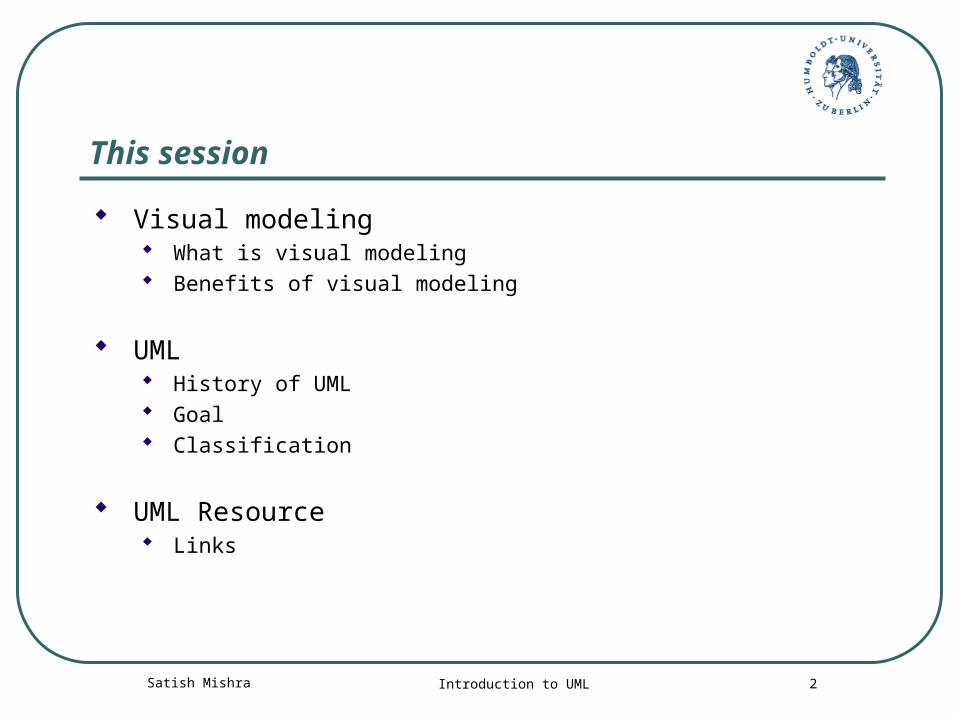
This session
Visual modeling What is visual modeling Benefits of visual modeling
UML History of UML Goal Classification
UML Resource Links
Satish Mishra Introduction to UML 3
Definition of Visual Modeling
• Visual Modeling is a way of thinking about problems by using graphical models of real-world ideas.
• Mapping real-world process of a computer system with a graphical representation
Satish Mishra Introduction to UML 4
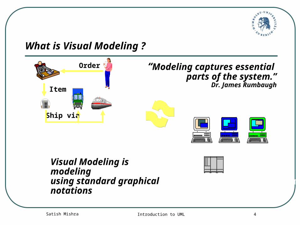
Computer System
Business Process
Order
Item
Ship via
“Modeling captures essential parts of the system.”
Dr. James Rumbaugh
Visual Modeling is modelingusing standard graphical notations
What is Visual Modeling ?
Satish Mishra Introduction to UML 5
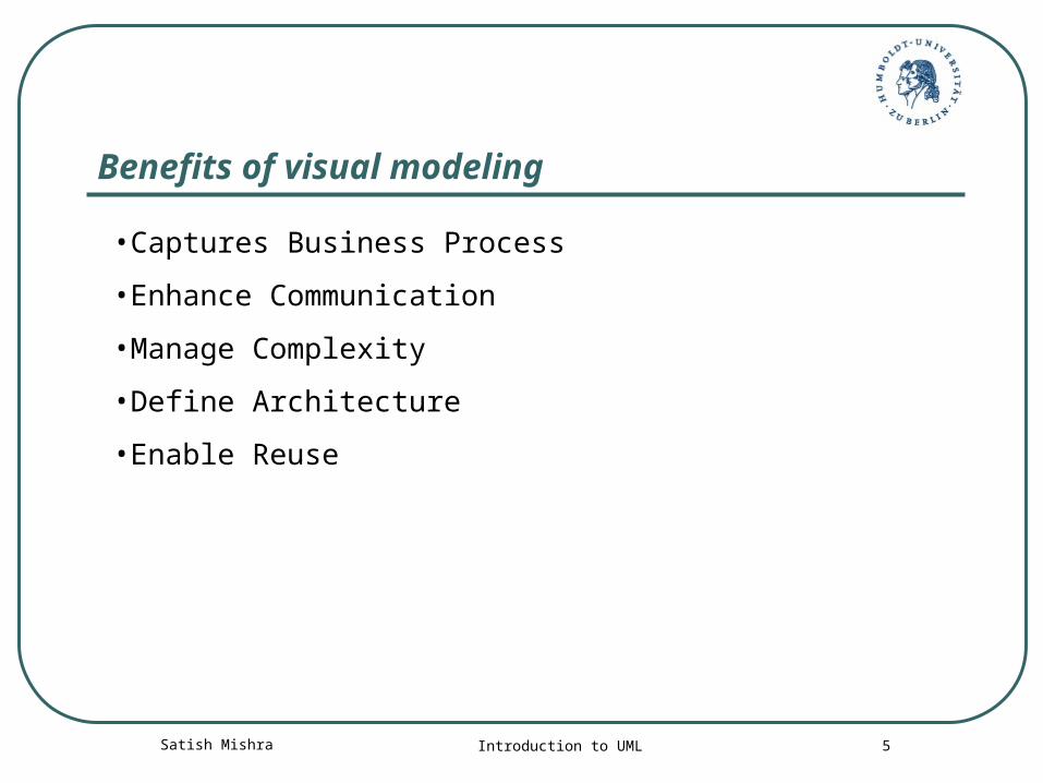
Benefits of visual modeling
•Captures Business Process
•Enhance Communication
•Manage Complexity
•Define Architecture
•Enable Reuse
Satish Mishra Introduction to UML 6
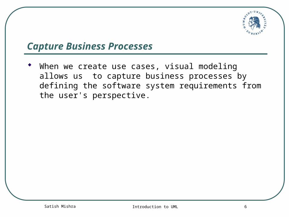
Capture Business Processes
When we create use cases, visual modeling allows us to capture business processes by defining the software system requirements from the user's perspective.
Satish Mishra Introduction to UML 7
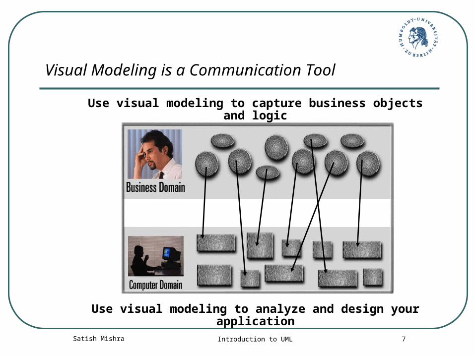
Visual Modeling is a Communication Tool
Use visual modeling to capture business objects and logic
Use visual modeling to analyze and design your application
Satish Mishra Introduction to UML 8
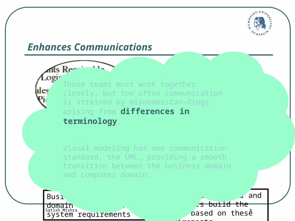
Enhances Communications
Business analysts and domain experts define system requirements
Software architects and developers build the system based on these requirements
These teams must work together closely, but too often communication is strained by misunderstan-dings arising from differences in terminology.
Visual modeling has one communication standard, the UML, providing a smooth transition between the business domain and computer domain.
Satish Mishra Introduction to UML 9
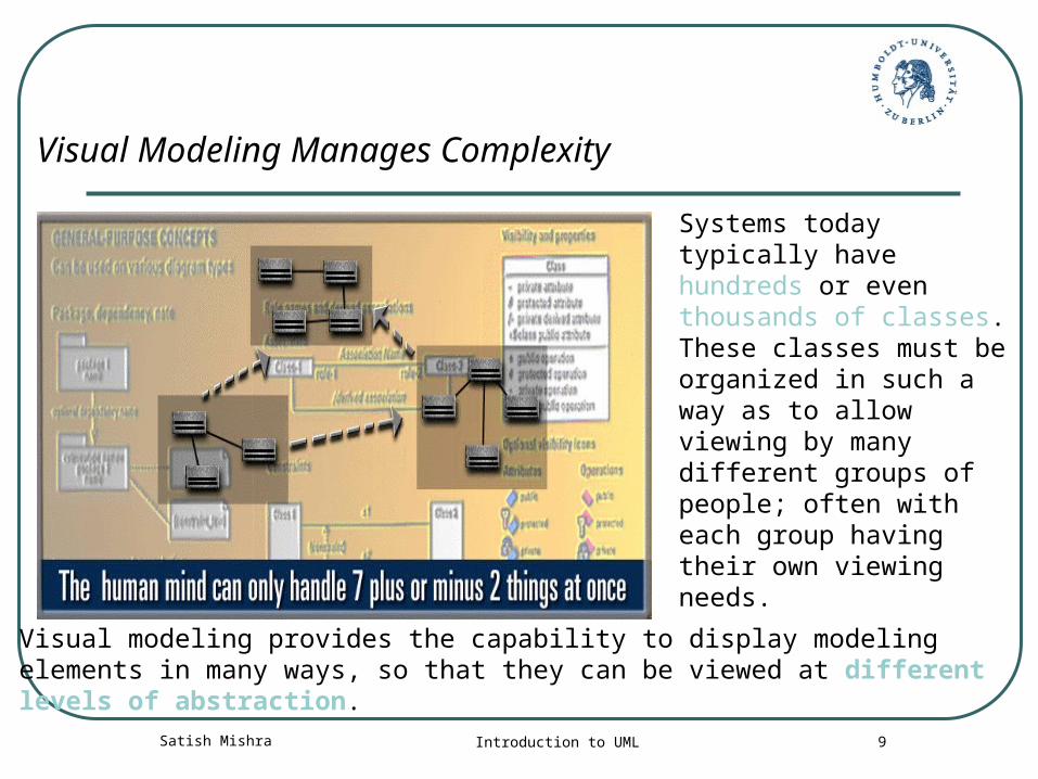
Visual Modeling Manages Complexity
Systems today typically have hundreds or even thousands of classes.These classes must be organized in such a way as to allow viewing by many different groups of people; often with each group having their own viewing needs.
Visual modeling provides the capability to display modeling elements in many ways, so that they can be viewed at different levels of abstraction.
Satish Mishra Introduction to UML 10
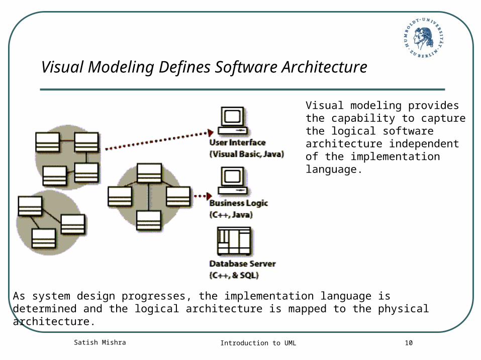
Visual Modeling Defines Software Architecture
Visual modeling provides the capability to capture the logical software architecture independent of the implementation language.
As system design progresses, the implementation language is determined and the logical architecture is mapped to the physical architecture.
Satish Mishra Introduction to UML 11
Multiple Systems
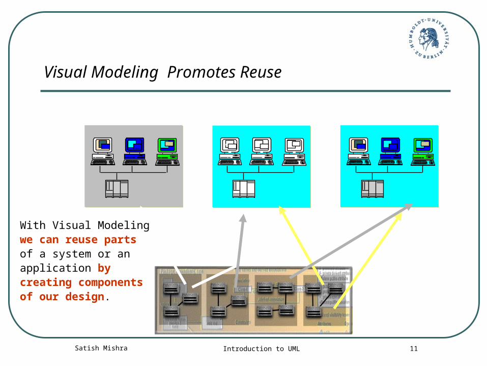
Visual Modeling Promotes Reuse
ReusableComponents
With Visual Modeling we can reuse parts of a system or an application by creating components of our design.
Satish Mishra Introduction to UML 12
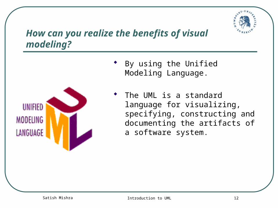
How can you realize the benefits of visual modeling?
By using the Unified Modeling Language.
The UML is a standard language for visualizing, specifying, constructing and documenting the artifacts of a software system.
Satish Mishra Introduction to UML 13
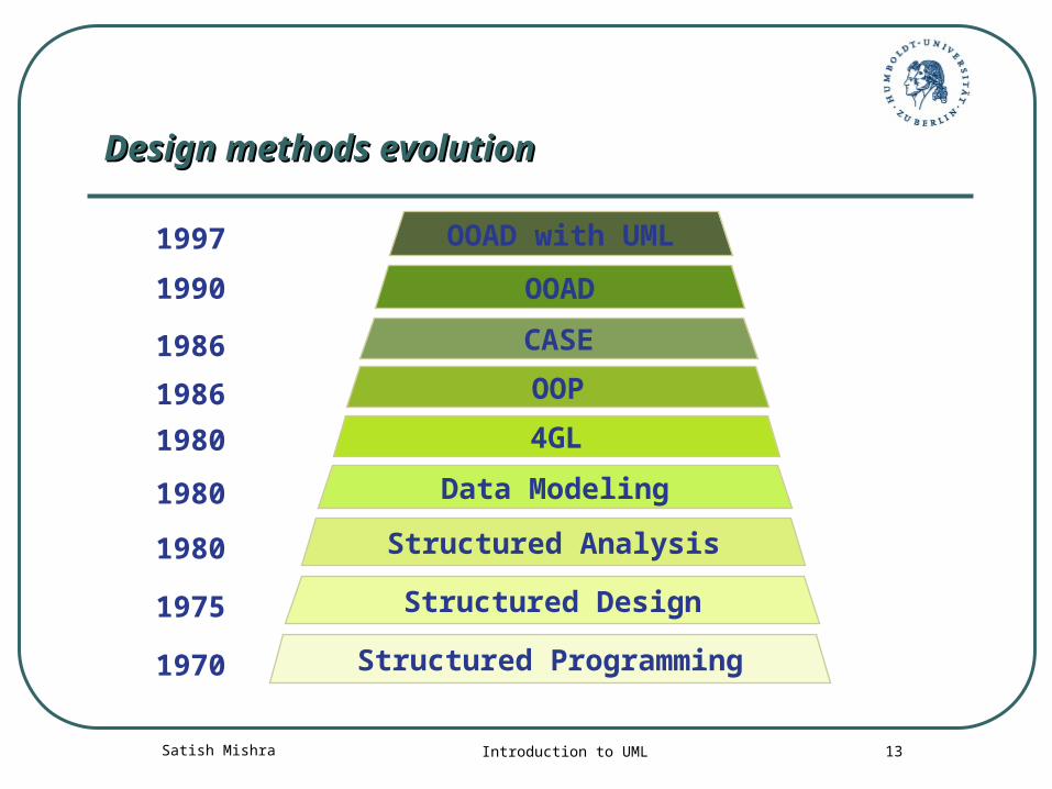
Design methods evolutionDesign methods evolution
Structured Programming
Structured Design
Structured Analysis
Data Modeling
4GL
OOP
CASE
OOAD
OOAD with UML
1970
1975
1980
1980
1980
1986
1986
1990
1997
Satish Mishra Introduction to UML 14
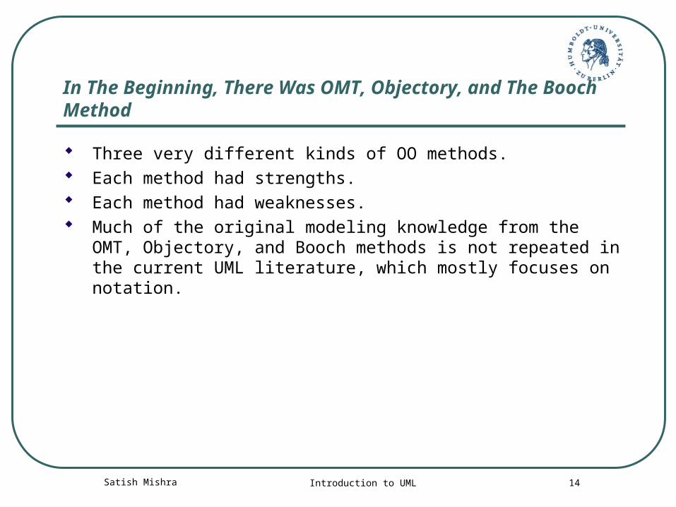
In The Beginning, There Was OMT, Objectory, and The Booch Method
Three very different kinds of OO methods. Each method had strengths. Each method had weaknesses. Much of the original modeling knowledge from the OMT,
Objectory, and Booch methods is not repeated in the current UML literature, which mostly focuses on notation.
Satish Mishra Introduction to UML 15
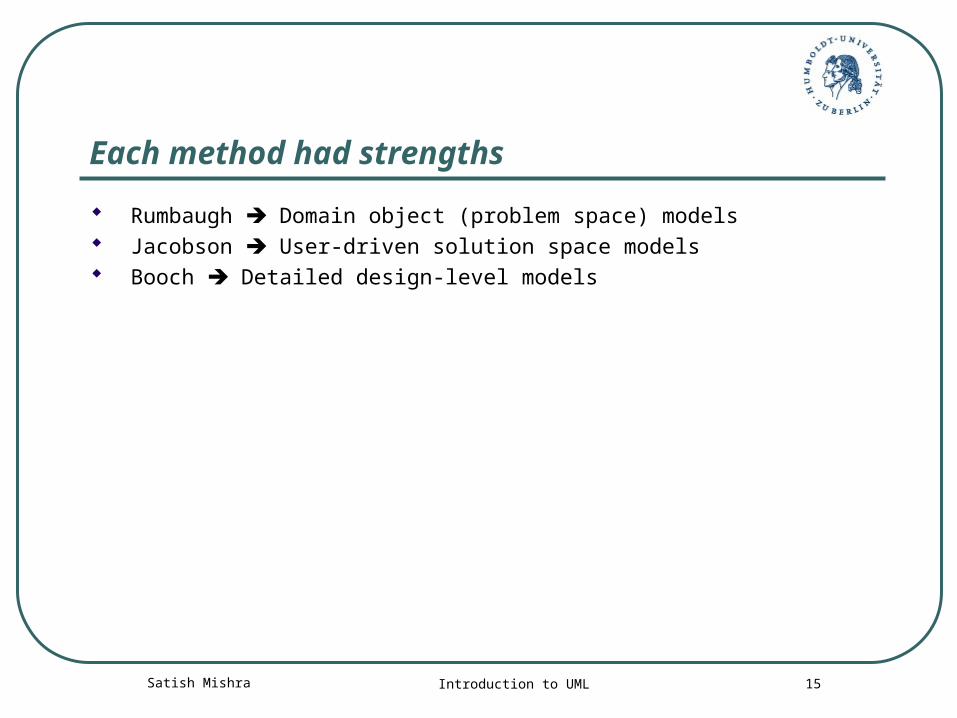
Each method had strengths
Rumbaugh Domain object (problem space) models Jacobson User-driven solution space models Booch Detailed design-level models
Satish Mishra Introduction to UML 16
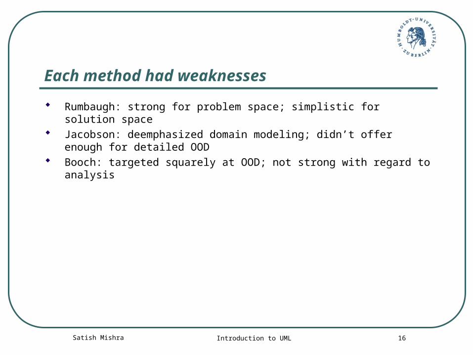
Each method had weaknesses
Rumbaugh: strong for problem space; simplistic for solution space Jacobson: deemphasized domain modeling; didn’t offer enough for
detailed OOD Booch: targeted squarely at OOD; not strong with regard to analysis
Satish Mishra Introduction to UML 17
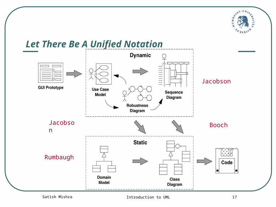
Let There Be A Unified Notation
Jacobson Booch
Jacobson
Rumbaugh
Satish Mishra Introduction to UML 18
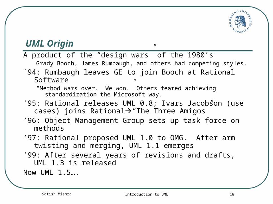
UML OriginA product of the “design wars” of the 1980’s
Grady Booch, James Rumbaugh, and others had competing styles.
`94: Rumbaugh leaves GE to join Booch at Rational Software“Method wars over. We won.” Others feared achieving
standardization the Microsoft way.
’95: Rational releases UML 0.8; Ivars Jacobson (use cases) joins Rational“The Three Amigos”
’96: Object Management Group sets up task force on methods
’97: Rational proposed UML 1.0 to OMG. After arm twisting and merging, UML 1.1 emerges
’99: After several years of revisions and drafts, UML 1.3 is released
Now UML 1.5….
Satish Mishra Introduction to UML 19Copyright © 1997 by Rational Software Corporation
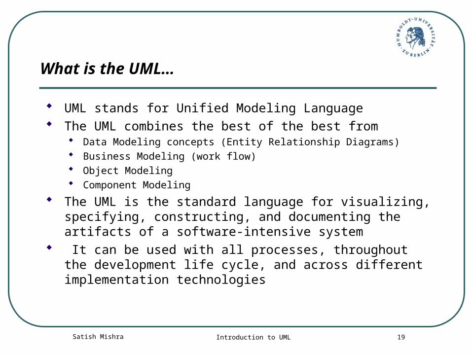
What is the UML…
UML stands for Unified Modeling Language The UML combines the best of the best from
Data Modeling concepts (Entity Relationship Diagrams) Business Modeling (work flow) Object Modeling Component Modeling
The UML is the standard language for visualizing, specifying, constructing, and documenting the artifacts of a software-intensive system
It can be used with all processes, throughout the development life cycle, and across different implementation technologies
Satish Mishra Introduction to UML 20
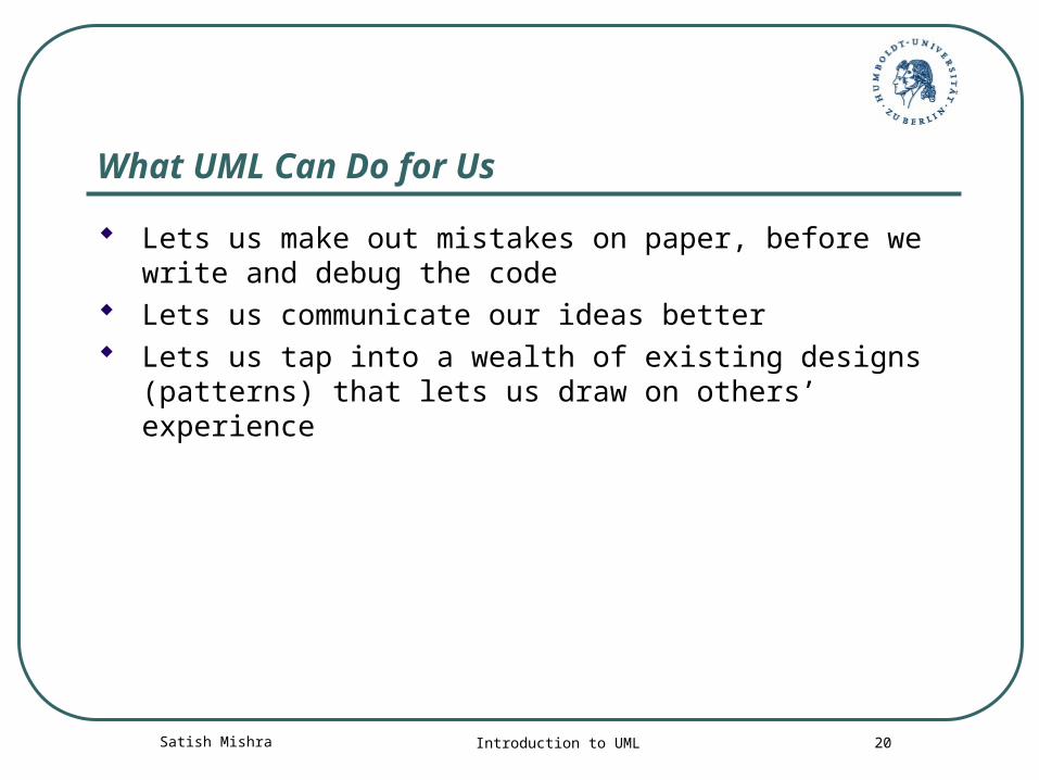
What UML Can Do for Us
Lets us make out mistakes on paper, before we write and debug the code
Lets us communicate our ideas better Lets us tap into a wealth of existing designs (patterns)
that lets us draw on others’ experience
Satish Mishra Introduction to UML 21
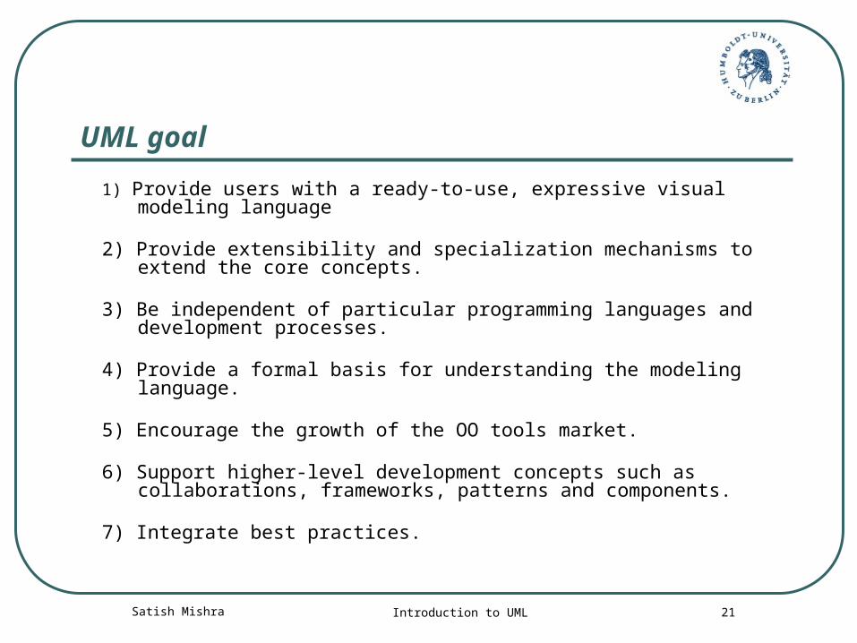
UML goal
1) Provide users with a ready-to-use, expressive visual modeling language
2) Provide extensibility and specialization mechanisms to extend the core concepts.
3) Be independent of particular programming languages and development processes.
4) Provide a formal basis for understanding the modeling language.
5) Encourage the growth of the OO tools market.
6) Support higher-level development concepts such as collaborations, frameworks, patterns and components.
7) Integrate best practices.
Satish Mishra Introduction to UML 22
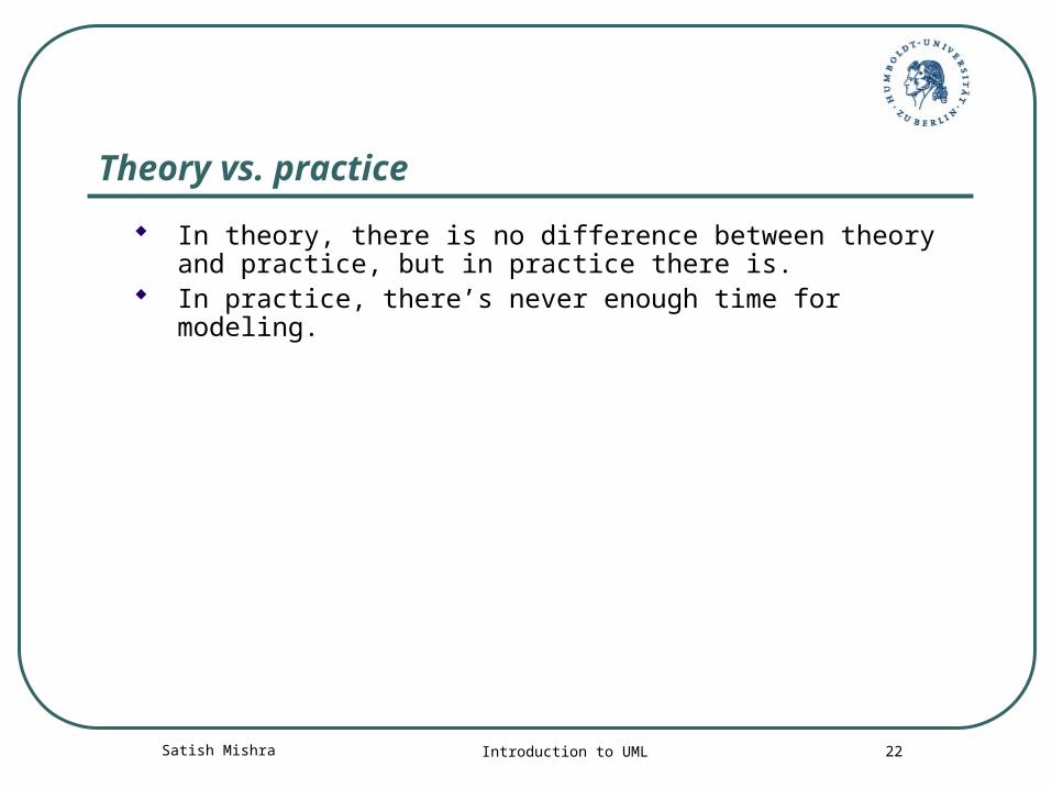
Theory vs. practice
In theory, there is no difference between theory and practice, but in practice there is.
In practice, there’s never enough time for modeling.
Satish Mishra Introduction to UML 23
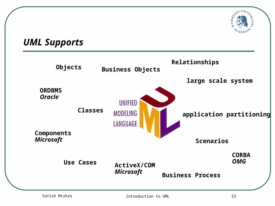
UML Supports
Classesapplication partitioning
Business ObjectsRelationships
Business Process
Objects
Use Cases
large scale system
ScenariosComponentsMicrosoft
ActiveX/COMMicrosoft
ORDBMSOracle
CORBAOMG
Satish Mishra Introduction to UML 24Copyright © 1997 by Rational Software Corporation
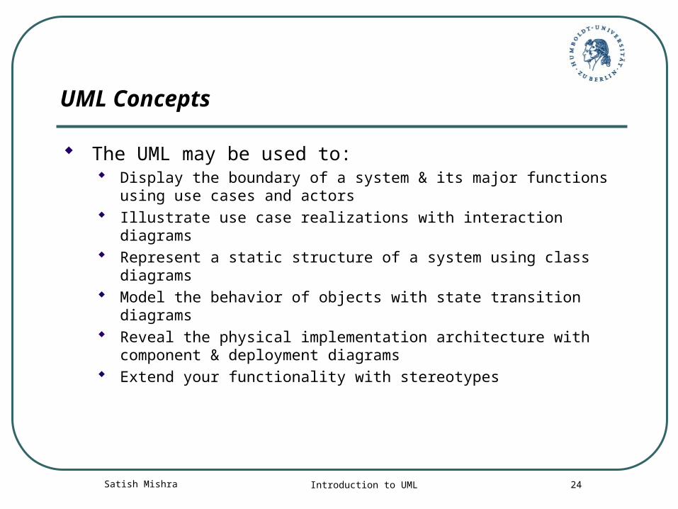
UML Concepts
The UML may be used to: Display the boundary of a system & its major functions using use
cases and actors Illustrate use case realizations with interaction diagrams Represent a static structure of a system using class diagrams Model the behavior of objects with state transition diagrams Reveal the physical implementation architecture with component
& deployment diagrams Extend your functionality with stereotypes
Satish Mishra Introduction to UML 25
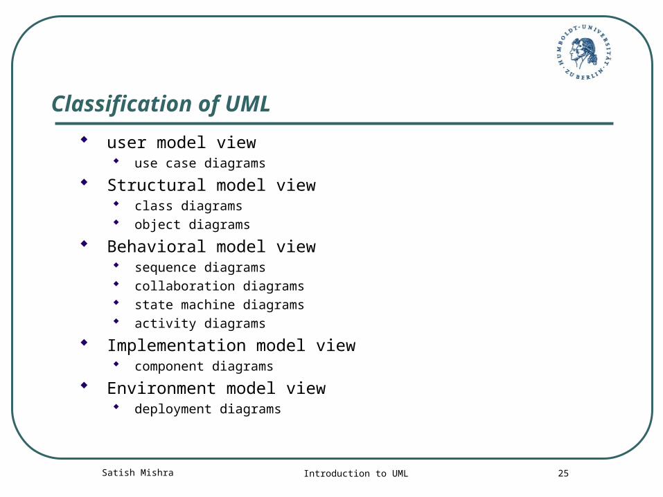
Classification of UML
user model view use case diagrams
Structural model view class diagrams object diagrams
Behavioral model view sequence diagrams collaboration diagrams state machine diagrams activity diagrams
Implementation model view component diagrams
Environment model view deployment diagrams
Satish Mishra Introduction to UML 26
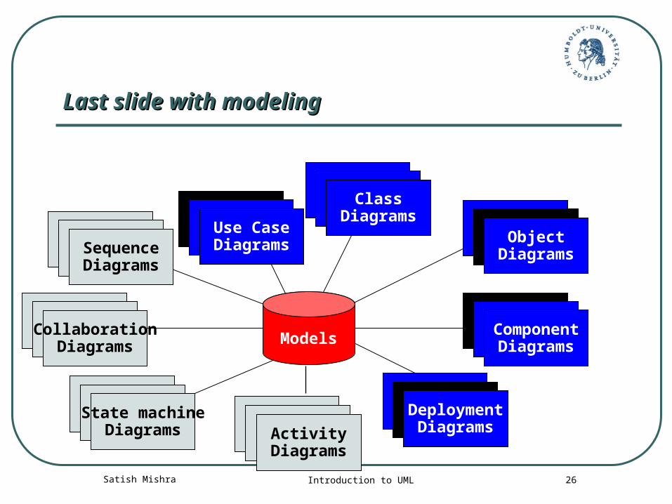
Last slide with modelingLast slide with modeling
Use CaseDiagramsUse Case
DiagramsUse CaseDiagrams
ScenarioDiagramsScenario
DiagramsCollaborationDiagrams
StateDiagramsState
DiagramsComponentDiagrams
ComponentDiagramsComponent
DiagramsDeploymentDiagrams
StateDiagramsState
DiagramsObjectDiagrams
ScenarioDiagramsScenario
DiagramsState machineDiagrams
Use CaseDiagramsUse Case
DiagramsSequenceDiagrams
StateDiagramsState
DiagramsClassDiagrams
ActivityDiagrams
Models
Satish Mishra Introduction to UML 27
Exercise
(As we all know Class Model)
Try to make Class Model for a banking system ?
!! Now !!
Satish Mishra Introduction to UML 28
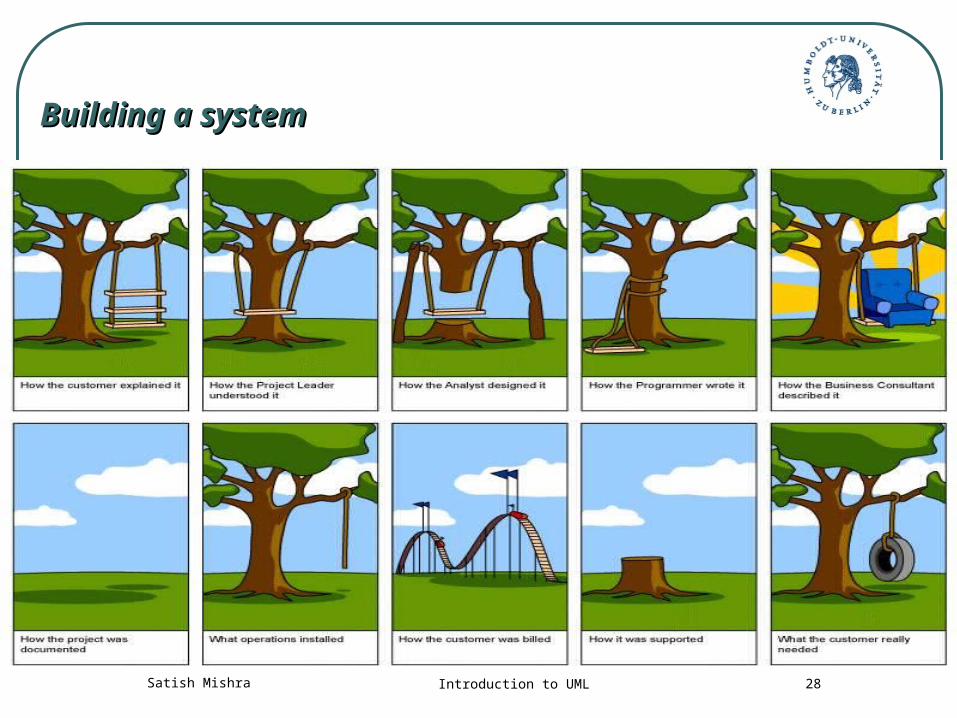
Building a systemBuilding a system
Satish Mishra Introduction to UML 29
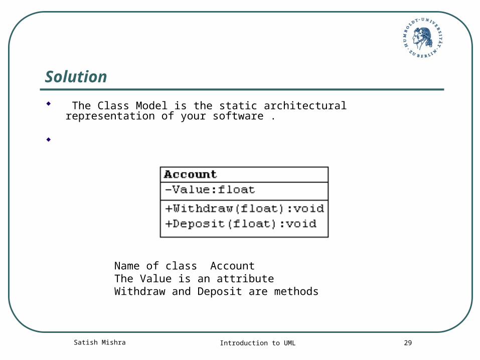
Solution
The Class Model is the static architectural representation of your software .
Name of class Account The Value is an attribute Withdraw and Deposit are methods
Satish Mishra Introduction to UML 30
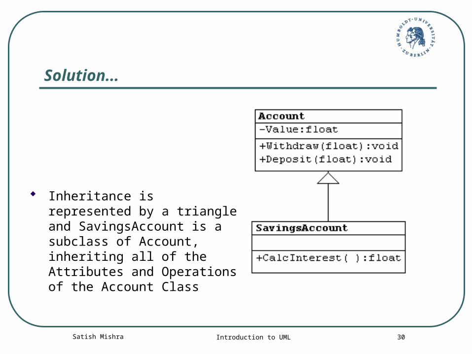
Solution...
Inheritance is represented by a triangle and SavingsAccount is a subclass of Account, inheriting all of the Attributes and Operations of the Account Class
Satish Mishra Introduction to UML 31
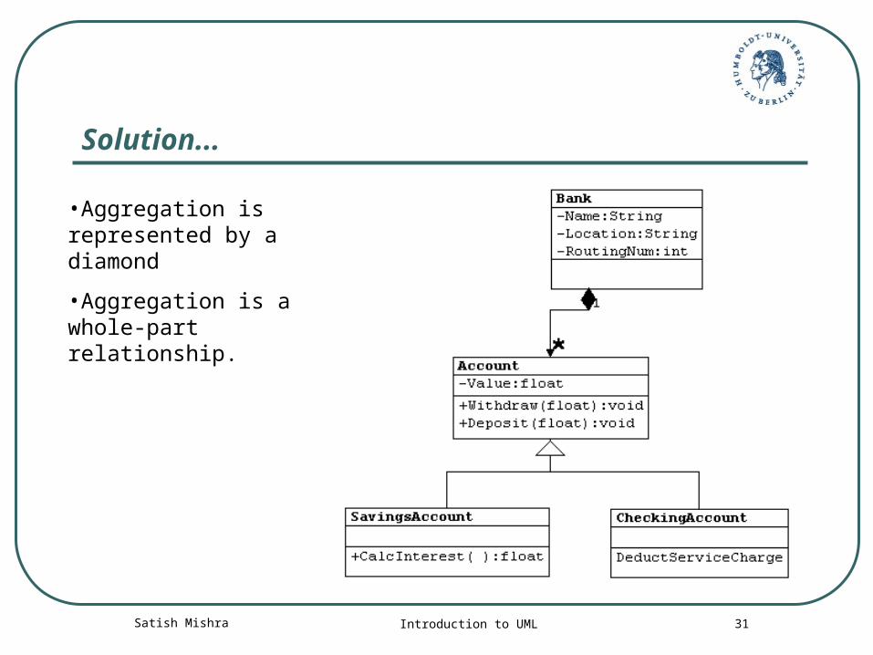
Solution...
•Aggregation is represented by a diamond
•Aggregation is a whole-part relationship.
Satish Mishra Introduction to UML 32
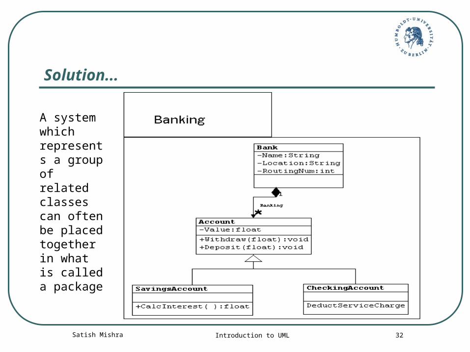
Solution...
A system which represents a group of related classes can often be placed together in what is called a package
Satish Mishra Introduction to UML 33
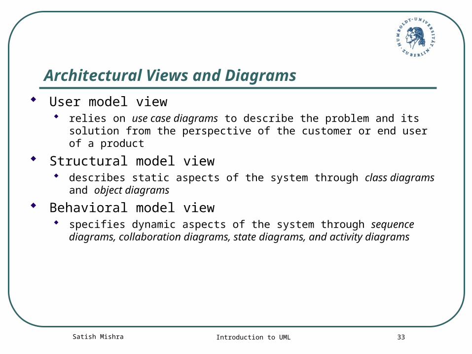
Architectural Views and Diagrams
User model view relies on use case diagrams to describe the problem and its solution
from the perspective of the customer or end user of a product
Structural model view describes static aspects of the system through class diagrams and
object diagrams
Behavioral model view specifies dynamic aspects of the system through sequence diagrams,
collaboration diagrams, state diagrams, and activity diagrams
Satish Mishra Introduction to UML 34
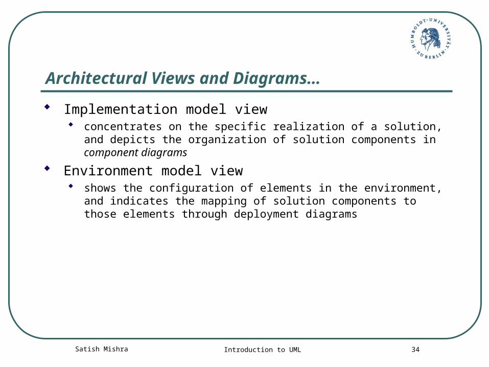
Architectural Views and Diagrams…
Implementation model view concentrates on the specific realization of a solution, and depicts
the organization of solution components in component diagrams
Environment model view shows the configuration of elements in the environment, and
indicates the mapping of solution components to those elements through deployment diagrams
Satish Mishra Introduction to UML 35
UML links
ArgoUML http://argouml.tigris.org/
Rational rose http://www-306.ibm.com/software/rational/
Link for UML tools http://www.objectsbydesign.com/tools/umltools_byCompany.html
UML specification http://www.uml.org/
For any detail http://www.google.com
Satish Mishra Introduction to UML 36
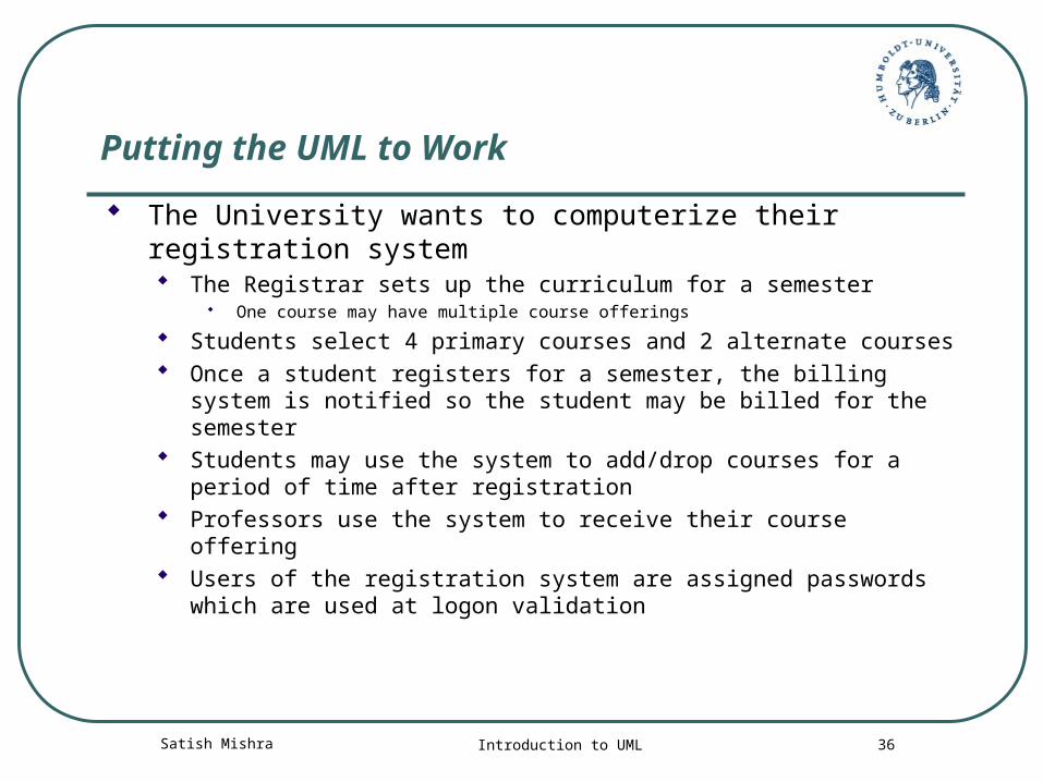
Putting the UML to Work
The University wants to computerize their registration system The Registrar sets up the curriculum for a semester
One course may have multiple course offerings
Students select 4 primary courses and 2 alternate courses Once a student registers for a semester, the billing system is
notified so the student may be billed for the semester Students may use the system to add/drop courses for a period of
time after registration Professors use the system to receive their course offering Users of the registration system are assigned passwords which
are used at logon validation
Satish Mishra Introduction to UML 37
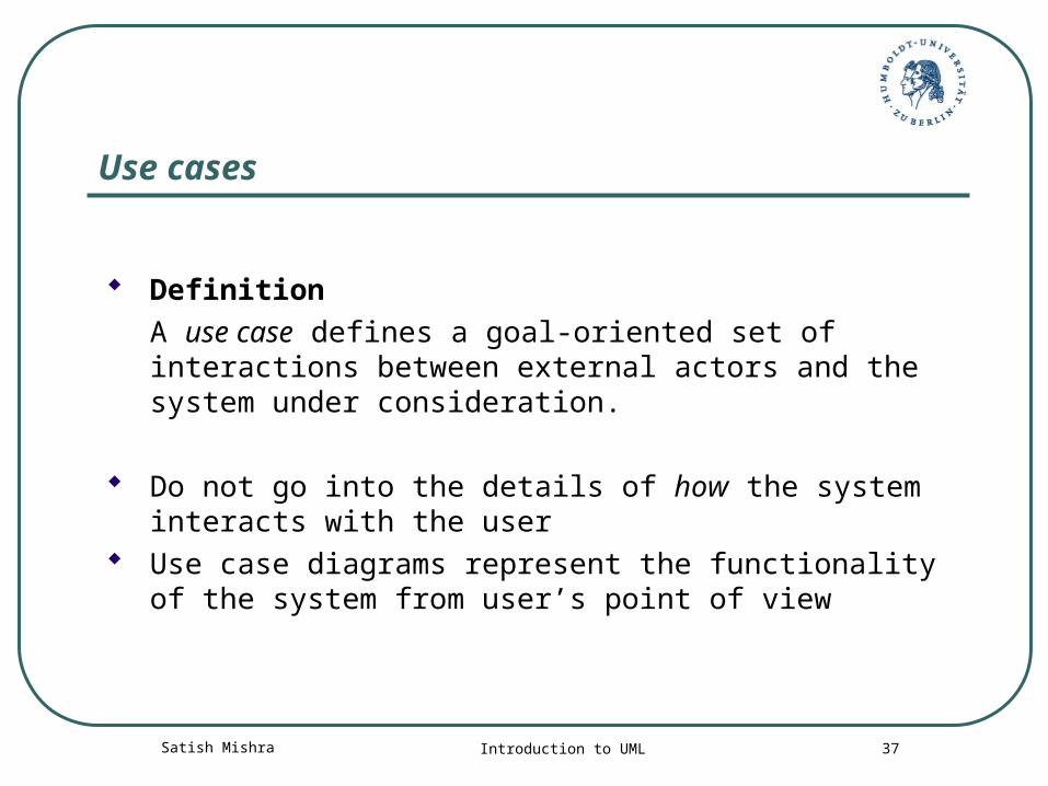
Use cases
DefinitionA use case defines a goal-oriented set of interactions between external actors and the system under consideration.
Do not go into the details of how the system interacts with the user
Use case diagrams represent the functionality of the system from user’s point of view
Satish Mishra Introduction to UML 38
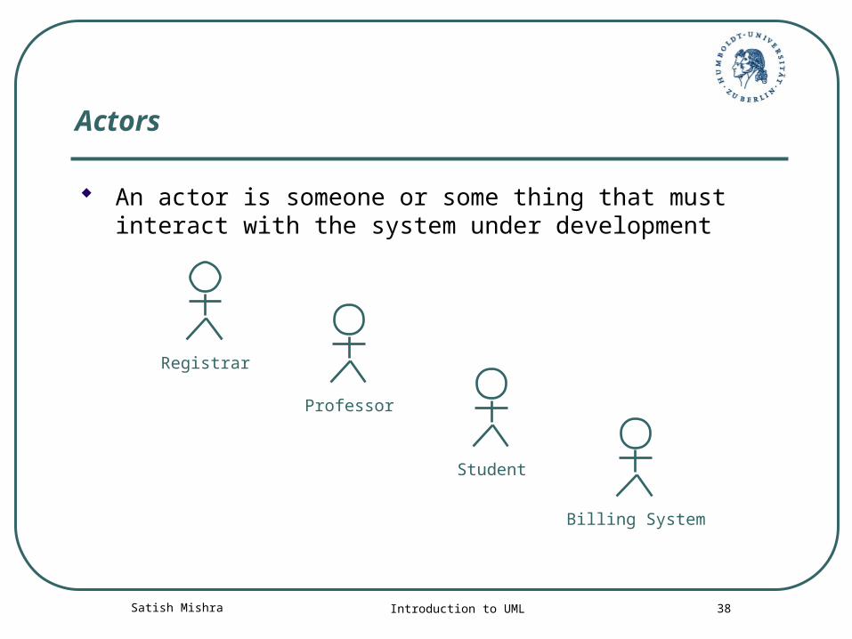
Actors
An actor is someone or some thing that must interact with the system under development
Student
Registrar
Professor
Billing System
Satish Mishra Introduction to UML 39
Use Cases
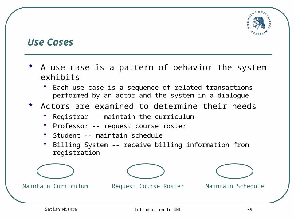
A use case is a pattern of behavior the system exhibits Each use case is a sequence of related transactions performed by
an actor and the system in a dialogue
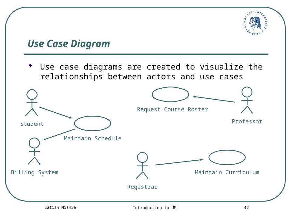
Actors are examined to determine their needs Registrar -- maintain the curriculum Professor -- request course roster Student -- maintain schedule Billing System -- receive billing information from registration
Maintain ScheduleMaintain Curriculum Request Course Roster
Satish Mishra Introduction to UML 40
Documenting Use Cases
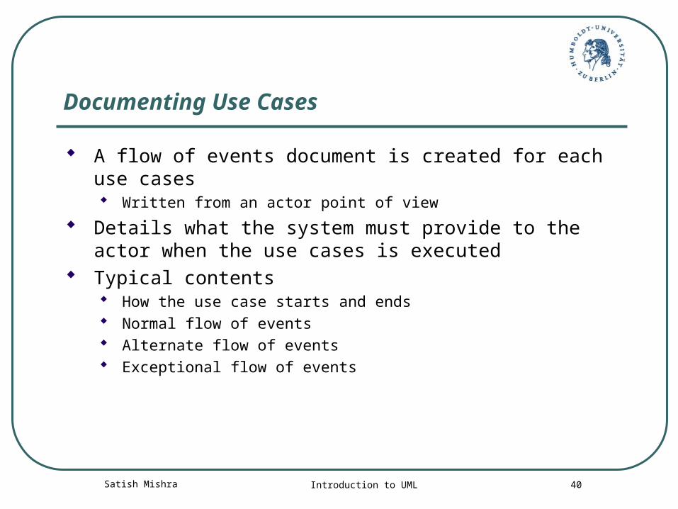
A flow of events document is created for each use cases Written from an actor point of view
Details what the system must provide to the actor when the use cases is executed
Typical contents How the use case starts and ends Normal flow of events Alternate flow of events Exceptional flow of events
Satish Mishra Introduction to UML 41
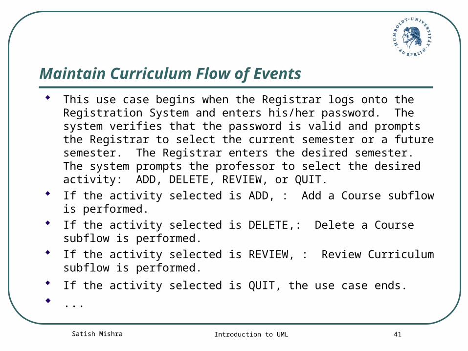
Maintain Curriculum Flow of Events
This use case begins when the Registrar logs onto the Registration System and enters his/her password. The system verifies that the password is valid and prompts the Registrar to select the current semester or a future semester. The Registrar enters the desired semester. The system prompts the professor to select the desired activity: ADD, DELETE, REVIEW, or QUIT.
If the activity selected is ADD, : Add a Course subflow is performed.
If the activity selected is DELETE,: Delete a Course subflow is performed.
If the activity selected is REVIEW, : Review Curriculum subflow is performed.
If the activity selected is QUIT, the use case ends. ...
Satish Mishra Introduction to UML 42
Use Case Diagram
Use case diagrams are created to visualize the relationships between actors and use cases
Student
Registrar
Professor
Maintain Schedule
Maintain Curriculum
Request Course Roster
Billing System
Satish Mishra Introduction to UML 43
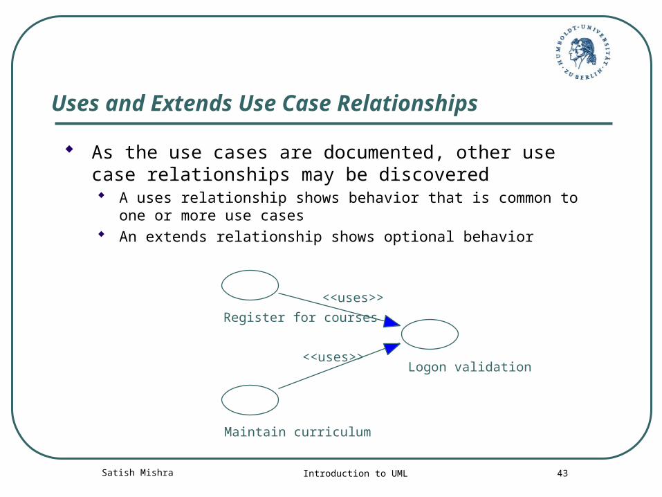
Uses and Extends Use Case Relationships
As the use cases are documented, other use case relationships may be discovered A uses relationship shows behavior that is common to one or
more use cases An extends relationship shows optional behavior
Register for courses
<<uses>>
Logon validation<<uses>>
Maintain curriculum
Satish Mishra Introduction to UML 44
Finding Primary Actors, Goals and Use Cases
Use cases are defined to satisfy the user goals of the actors.
The basic procedures are:1. Choose the system boundary. Is it just a software application, a mix of hardware
and software, that plus a person using it or an entire organization?
2. Identify the actors – those that have user goals fulfilled through using services of the system.
3. For each identify their user goals. Raise them to the highest user goal level.
4. Define use cases that satisfy user goals and name them according to their goal.
Satish Mishra Introduction to UML 45
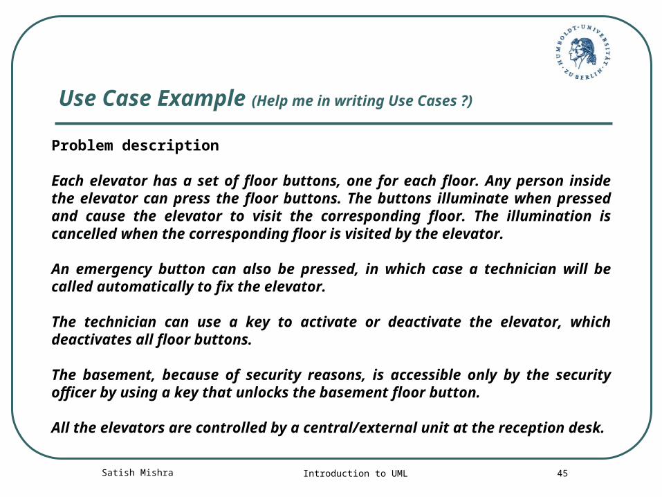
Use Case Example (Help me in writing Use Cases ?)
Problem description Each elevator has a set of floor buttons, one for each floor. Any person inside the elevator can press the floor buttons. The buttons illuminate when pressed and cause the elevator to visit the corresponding floor. The illumination is cancelled when the corresponding floor is visited by the elevator. An emergency button can also be pressed, in which case a technician will be called automatically to fix the elevator. The technician can use a key to activate or deactivate the elevator, which deactivates all floor buttons. The basement, because of security reasons, is accessible only by the security officer by using a key that unlocks the basement floor button. All the elevators are controlled by a central/external unit at the reception desk.

Satish Mishra Introduction to UML 46
Use Case Example
Actors and goals:
• Floor visitor - visit a floor, call a technician;
• Technician – activate the elevator, deactivate the elevator, repair the elevator;
• Security officer - visit the basement, visit a floor, call technician;
• Central unit – control the elevator.
Satish Mishra Introduction to UML 47
Class Diagrams
A class diagram shows the existence of classes and their relationships in the logical view of a system
UML modeling elements in class diagrams Classes and their structure and behavior Association, aggregation, dependency, and inheritance
relationships Multiplicity and navigation indicators Role names
Satish Mishra Introduction to UML 48
Classes
A class is a collection of objects with common structure, common behavior, common relationships and common semantics
Classes are found by examining the objects in sequence and collaboration diagram
A class is drawn as a rectangle with three compartments
Classes should be named using the vocabulary of the domain Naming standards should be created e.g., all classes are singular nouns starting with a capital letter
Satish Mishra Introduction to UML 49
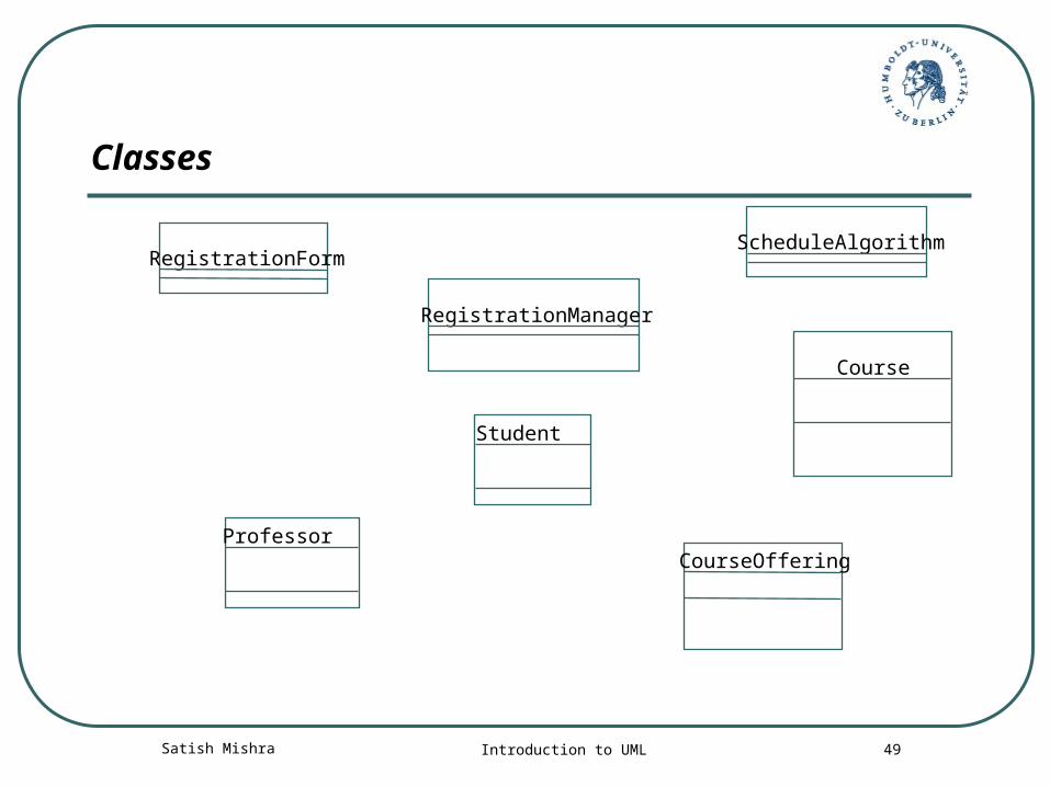
Classes
RegistrationForm
RegistrationManager
Course
Student
CourseOfferingProfessor
ScheduleAlgorithm
Satish Mishra Introduction to UML 50
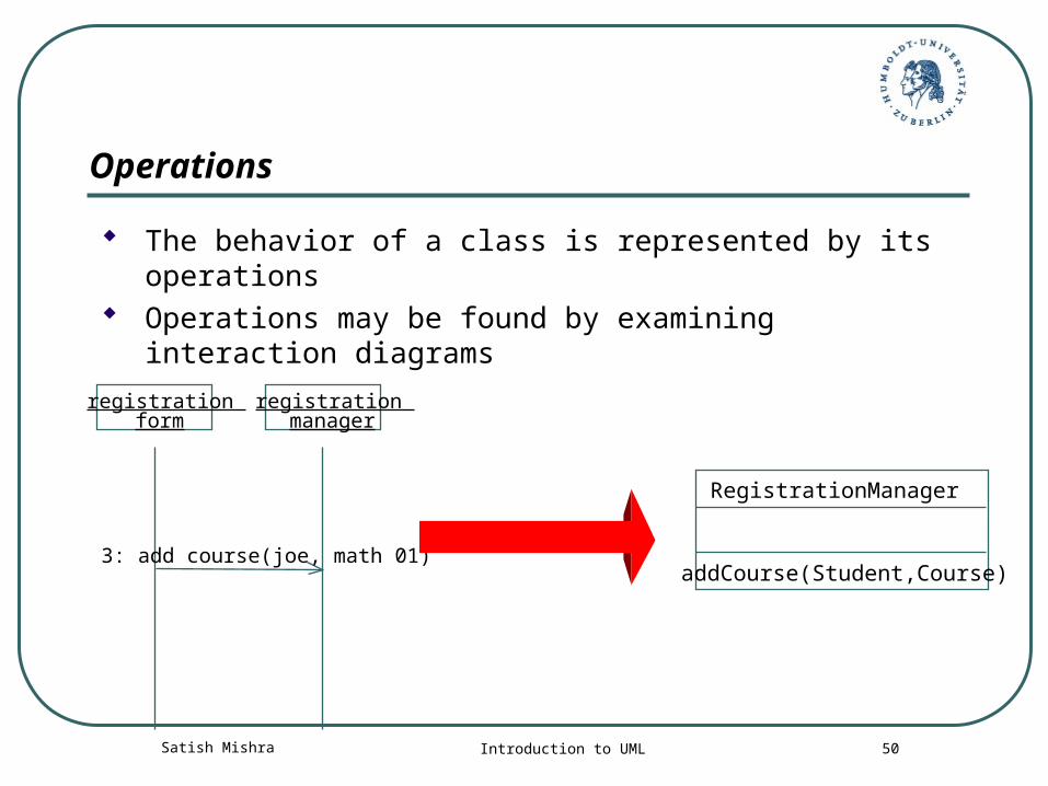
Operations
The behavior of a class is represented by its operations Operations may be found by examining interaction
diagrams
registration form
registration manager
3: add course(joe, math 01)
RegistrationManager
addCourse(Student,Course)
Satish Mishra Introduction to UML 51
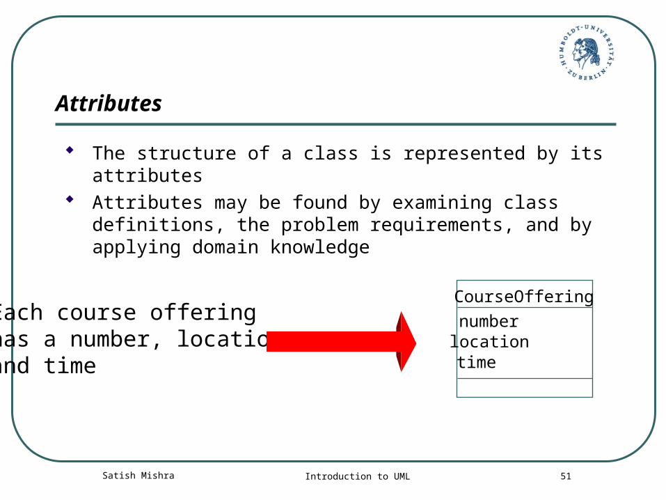
Attributes
The structure of a class is represented by its attributes Attributes may be found by examining class
definitions, the problem requirements, and by applying domain knowledge
Each course offeringhas a number, location and time
CourseOffering
numberlocationtime
Satish Mishra Introduction to UML 52
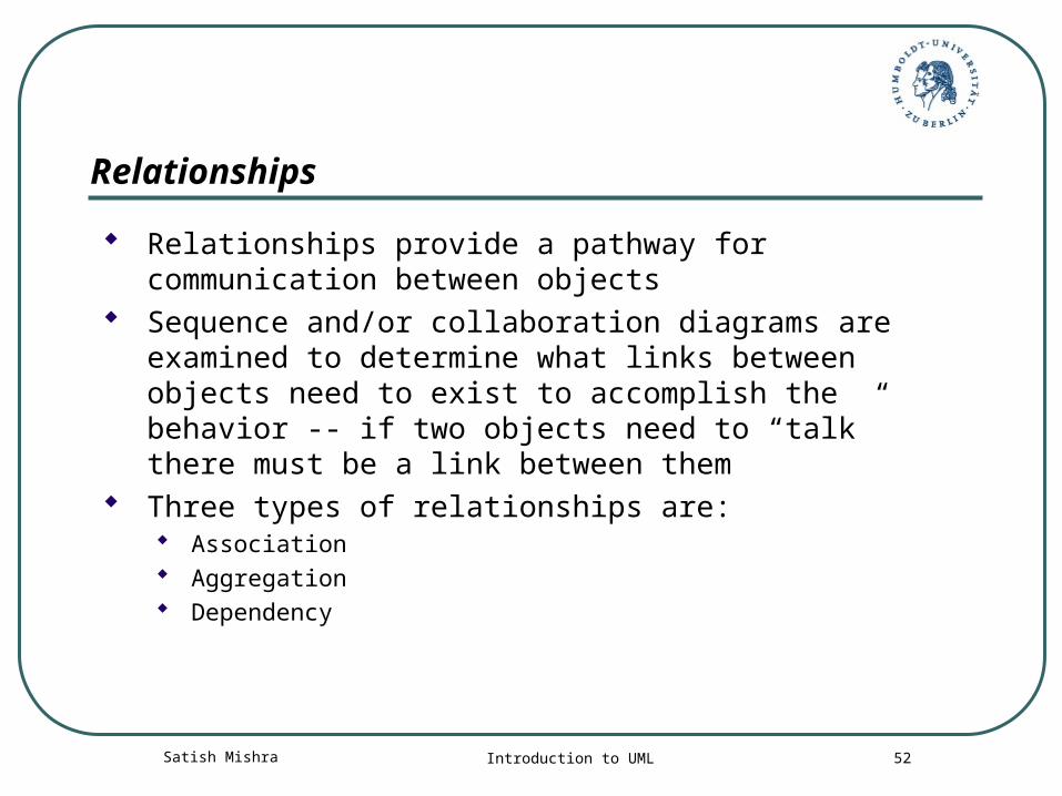
Relationships
Relationships provide a pathway for communication between objects
Sequence and/or collaboration diagrams are examined to determine what links between objects need to exist to accomplish the behavior -- if two objects need to “talk” there must be a link between them
Three types of relationships are: Association Aggregation Dependency
Satish Mishra Introduction to UML 53
Relationships
An association is a bi-directional connection between classes An association is shown as a line connecting the related classes
An aggregation is a stronger form of relationship where the relationship is between a whole and its parts An aggregation is shown as a line connecting the related classes with a diamond next to the
class representing the whole
A dependency relationship is a weaker form of relationship showing a relationship between a client and a supplier where the client does not have semantic knowledge of the supplier
A dependency is shown as a dashed line pointing from the client to the supplier
Satish Mishra Introduction to UML 54
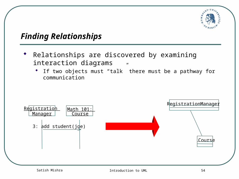
Registration Manager
Math 101: Course
3: add student(joe)
RegistrationManager
Course
Finding Relationships
Relationships are discovered by examining interaction diagrams If two objects must “talk” there must be a pathway for
communication
Satish Mishra Introduction to UML 55
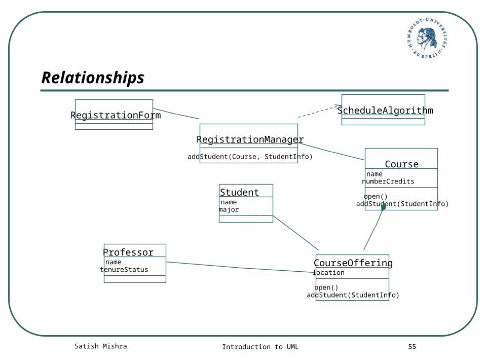
Relationships
RegistrationForm
RegistrationManager
Course
Student
CourseOfferingProfessor
addStudent(Course, StudentInfo)
namenumberCredits
open()addStudent(StudentInfo)name
major
location
open()addStudent(StudentInfo)
nametenureStatus
ScheduleAlgorithm
Satish Mishra Introduction to UML 56
Multiplicity and Navigation
Multiplicity defines how many objects participate in a relationships Multiplicity is the number of instances of one class related to ONE
instance of the other class For each association and aggregation, there are two multiplicity
decisions to make: one for each end of the relationship
Although associations and aggregations are bi-directional by default, it is often desirable to restrict navigation to one direction
If navigation is restricted, an arrowhead is added to indicate the direction of the navigation
Satish Mishra Introduction to UML 57
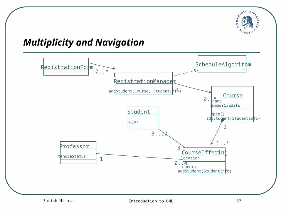
Multiplicity and Navigation
RegistrationForm
RegistrationManager
Course
Student
CourseOfferingProfessor
addStudent(Course, StudentInfo)
namenumberCredits
open()addStudent(StudentInfo)
major
location
open()addStudent(StudentInfo)
tenureStatus
ScheduleAlgorithm
10..*
0..*
1
1
1..*4
3..10
0..41
Satish Mishra Introduction to UML 58
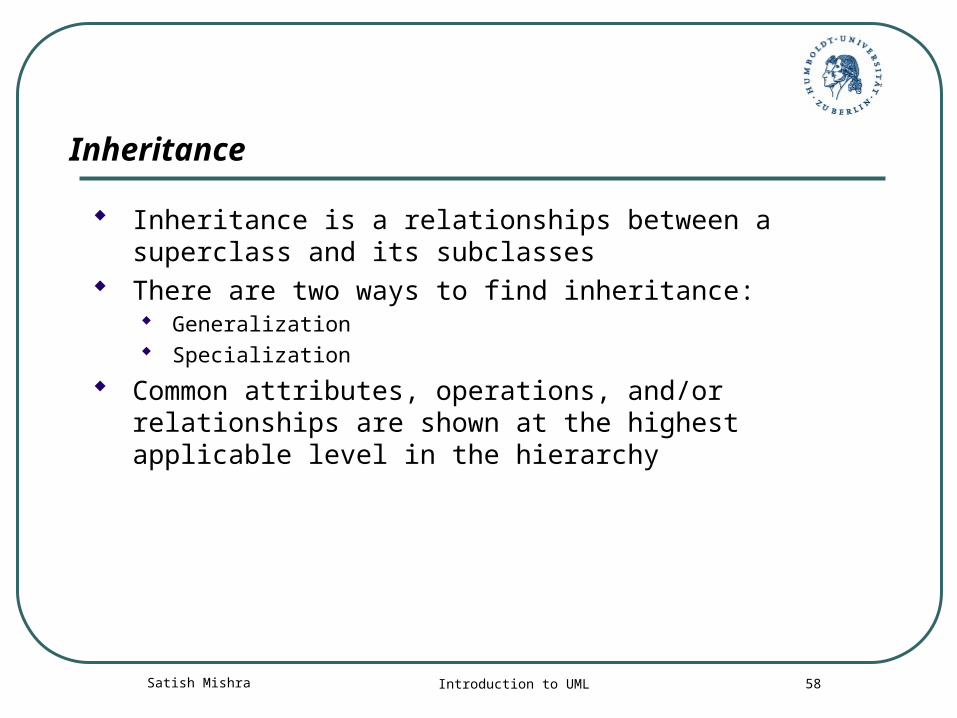
Inheritance
Inheritance is a relationships between a superclass and its subclasses
There are two ways to find inheritance: Generalization Specialization
Common attributes, operations, and/or relationships are shown at the highest applicable level in the hierarchy
Satish Mishra Introduction to UML 59Copyright © 1997 by Rational Software Corporation
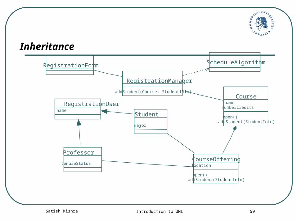
Inheritance
RegistrationForm
RegistrationManager
Course
Student
CourseOfferingProfessor
addStudent(Course, StudentInfo)
namenumberCredits
open()addStudent(StudentInfo)
major
location
open()addStudent(StudentInfo)
tenureStatus
ScheduleAlgorithm
name
RegistrationUser
Satish Mishra Introduction to UML 60
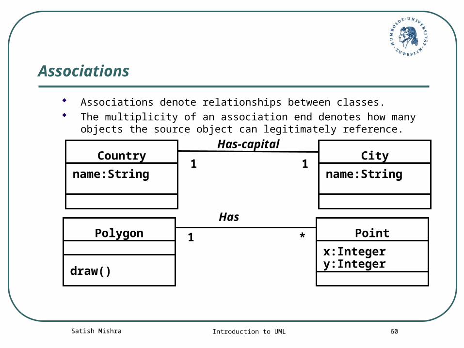
Associations
Associations denote relationships between classes. The multiplicity of an association end denotes how many objects the
source object can legitimately reference.
*
draw()
Polygon
x:Integery:Integer
Point1
Has-capital
name:String
Country
name:String
City11
Has
Satish Mishra Introduction to UML 61
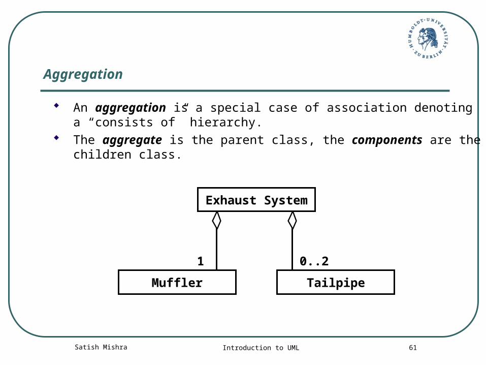
Aggregation
An aggregation is a special case of association denoting a “consists of” hierarchy.
The aggregate is the parent class, the components are the children class.
1
Exhaust System
Muffler Tailpipe
0..2
Satish Mishra Introduction to UML 62
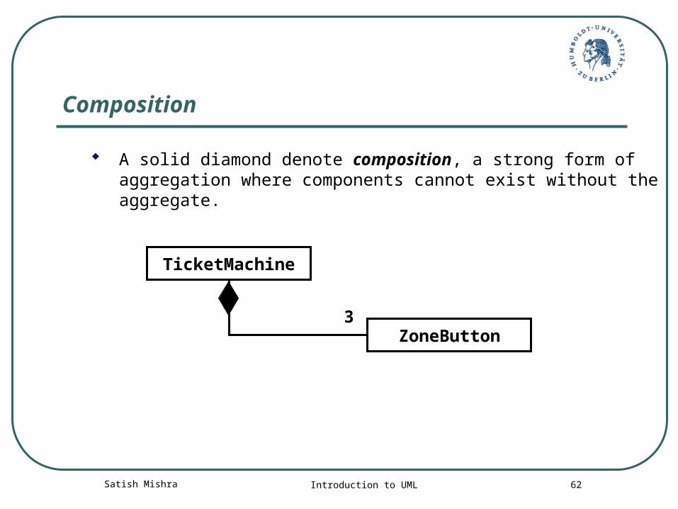
Composition
A solid diamond denote composition, a strong form of aggregation where components cannot exist without the aggregate.
3
TicketMachine
ZoneButton
Satish Mishra Introduction to UML 63
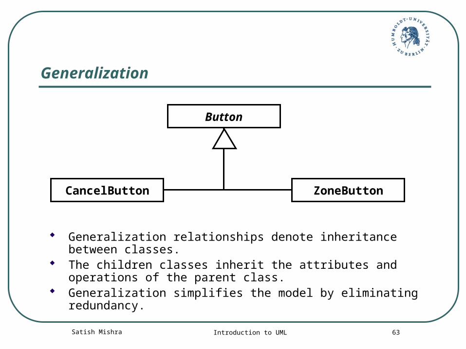
Generalization
Generalization relationships denote inheritance between classes.
The children classes inherit the attributes and operations of the parent class.
Generalization simplifies the model by eliminating redundancy.
Button
ZoneButtonCancelButton
Satish Mishra Introduction to UML 64
Behavioral /Dynamic Model View
State machine diagrams Activity diagrams Sequence diagrams Collaboration diagrams Object diagram
Satish Mishra Introduction to UML 65
State Machine Diagram
UML state machine diagrams depict the various states that an object
And the transitions between those states
State diagrams show the change of an object over time
Very useful for concurrent and real-time systems
Satish Mishra Introduction to UML 66
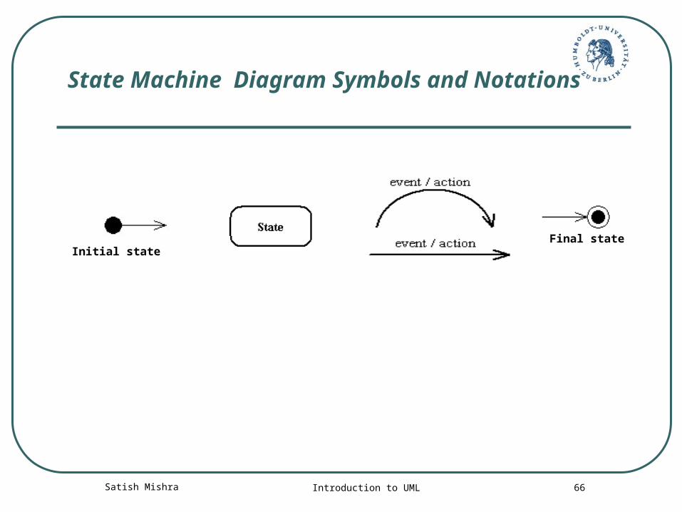
State Machine Diagram Symbols and Notations
Initial stateFinal state
Satish Mishra Introduction to UML 67
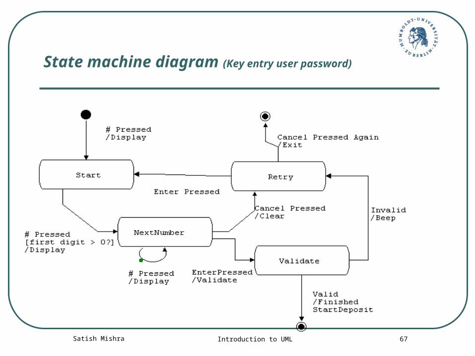
State machine diagram (Key entry user password)
Satish Mishra Introduction to UML 68
Activity Diagram:
Activity diagrams are typically used for business process modeling
For modeling the detailed logic of a business rule
Model the internal logic of a complex operation
An activity diagram is a special case of a state chart diagram in which states are activities (“functions”)
Activity diagrams are the object-oriented equivalent of flow charts and data flow diagrams (DFDs)
Satish Mishra Introduction to UML 69
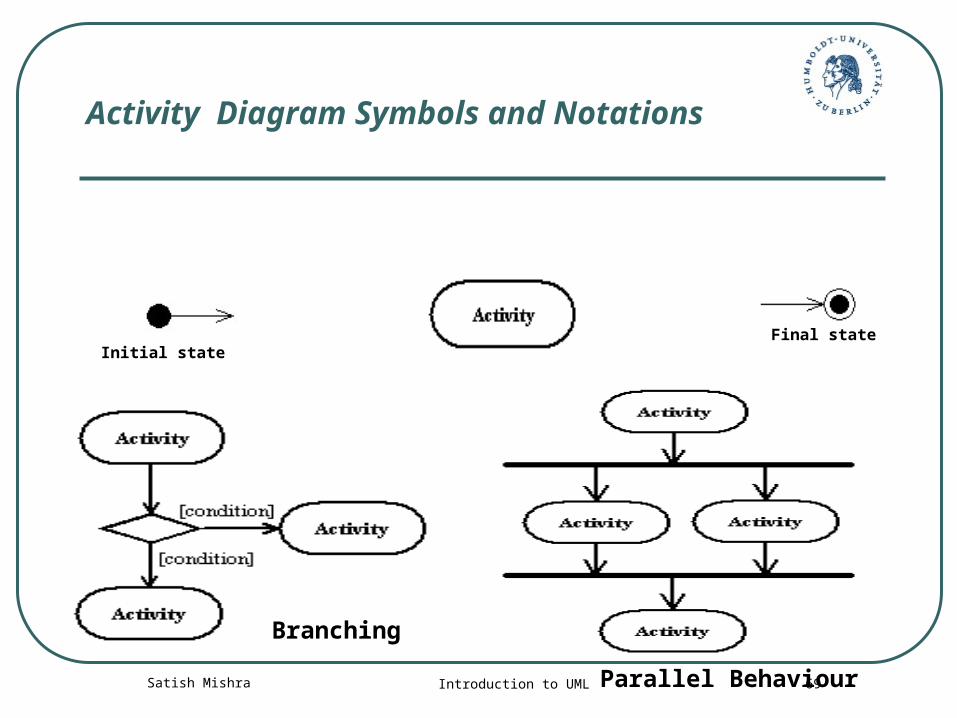
Activity Diagram Symbols and Notations
Initial stateFinal state
Branching
Parallel Behaviour
Satish Mishra Introduction to UML 70
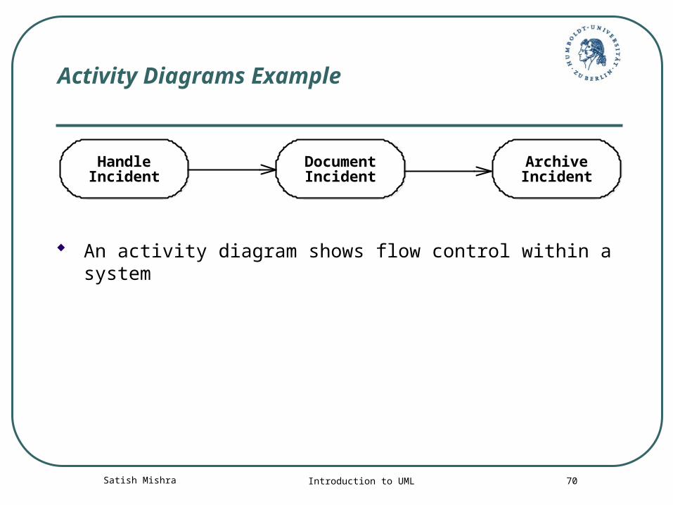
Activity Diagrams Example
An activity diagram shows flow control within a system
HandleIncident
DocumentIncident
ArchiveIncident
Satish Mishra Introduction to UML 71
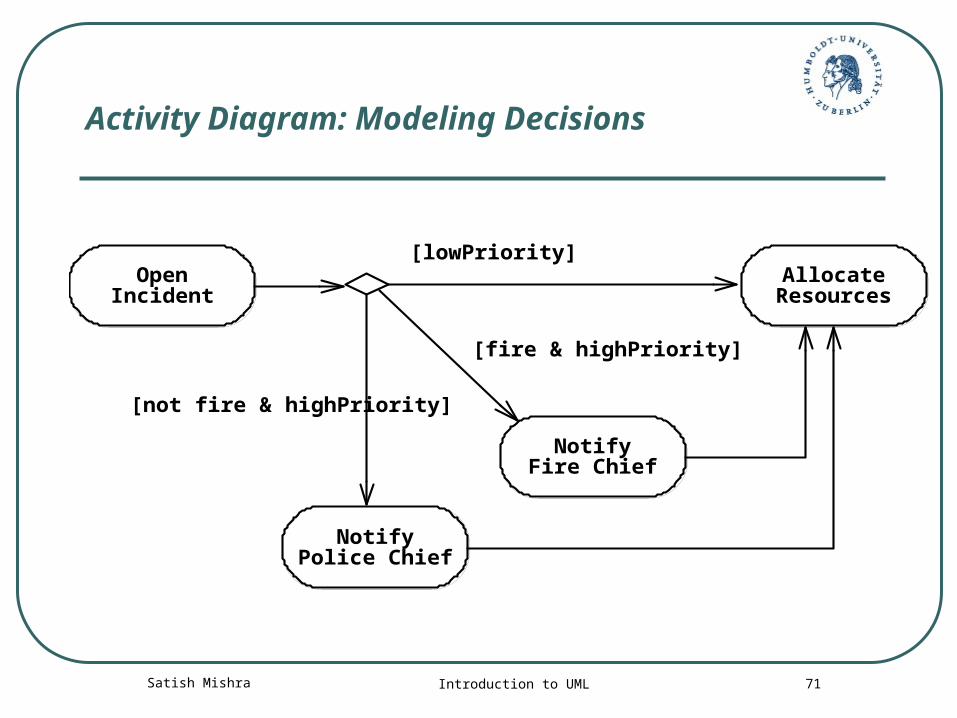
Activity Diagram: Modeling Decisions
OpenIncident
NotifyPolice Chief
NotifyFire Chief
AllocateResources
[fire & highPriority]
[not fire & highPriority]
[lowPriority]
Satish Mishra Introduction to UML 72
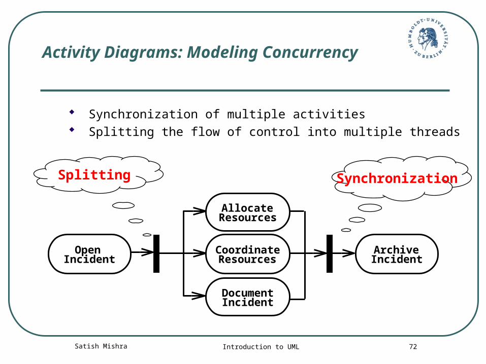
Activity Diagrams: Modeling Concurrency
Synchronization of multiple activities Splitting the flow of control into multiple threads
SynchronizationSplitting
ArchiveIncident
OpenIncident
DocumentIncident
AllocateResources
CoordinateResources
Satish Mishra Introduction to UML 73
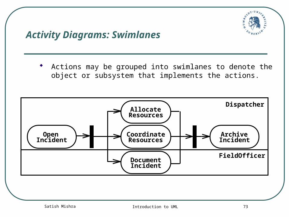
Activity Diagrams: Swimlanes
Actions may be grouped into swimlanes to denote the object or subsystem that implements the actions.
ArchiveIncident
Dispatcher
FieldOfficer
OpenIncident
DocumentIncident
AllocateResources
CoordinateResources
Satish Mishra Introduction to UML 74
When State and Activity Diagram
Activity diagrams are used to show workflow in parallel and conditionally. They are useful when working out the order and concurrency of a sequential algorithm, when analyzing the steps in a business process and when working with threads
State diagrams show the change of an object over time and are useful when an object exhibits interesting or unusual behaviour
Use these diagrams only when they serve a purpose. Don't feel that you have to draw a state diagram for every object in your system and an activity diagram for every process
Satish Mishra Introduction to UML 75
Interaction diagram
Interaction diagrams describe how use cases are realized as interactions among societies of objects
Use case shows an interaction between a user and a system
Interaction diagram captures the behaviour of a single case by showing the collaboration of the objects in the system to accomplish the task
Two types of interaction diagrams Sequence diagrams Collaboration diagrams
Satish Mishra Introduction to UML 76
Sequence diagrams
The sequence diagram describes the flow of messages being passed from object to object
Satish Mishra Introduction to UML 77
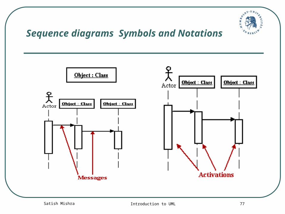
Sequence diagrams Symbols and Notations
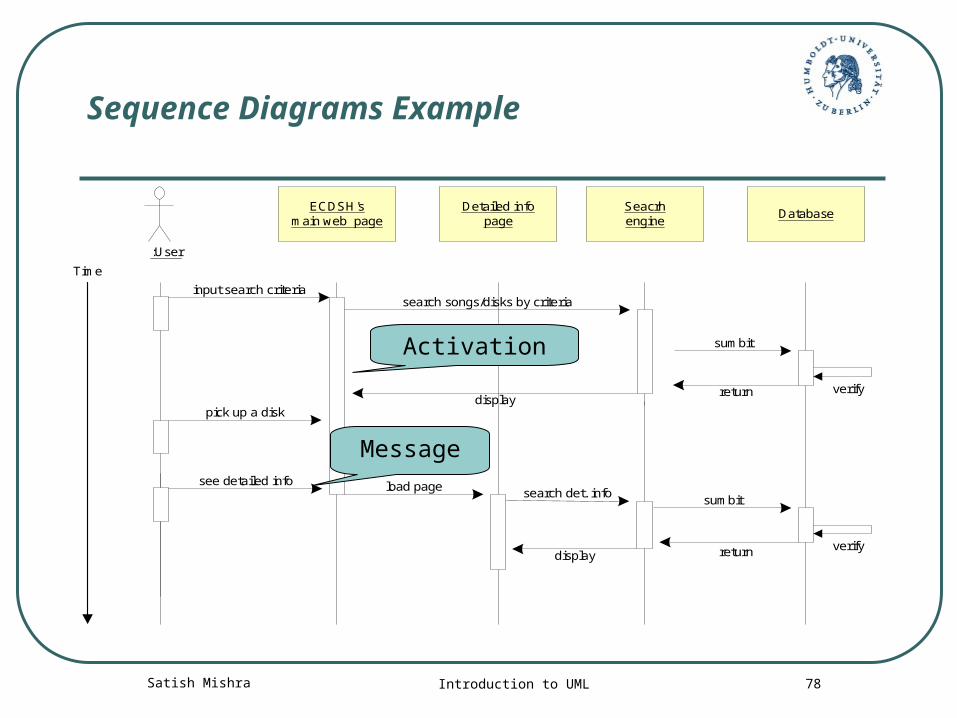
Satish Mishra Introduction to UML 78
Sequence Diagrams Example
:User
ECDSH'smain web page
input search criteria
displaypick up a disk
Detailed infopage
Database
search songs/disks by criteria
sumbit
verifyreturn
load pagesumbit
returndisplayverify
Time
see detailed info
Seacrhengine
search det. info
Activation
Message
Satish Mishra Introduction to UML 79
Collaboration diagrams
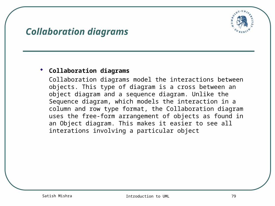
Collaboration diagrams Collaboration diagrams model the interactions between objects.
This type of diagram is a cross between an object diagram and a sequence diagram. Unlike the Sequence diagram, which models the interaction in a column and row type format, the Collaboration diagram uses the free-form arrangement of objects as found in an Object diagram. This makes it easier to see all interations involving a particular object
Satish Mishra Introduction to UML 80
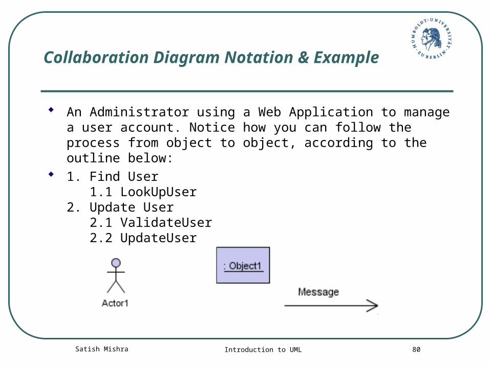
Collaboration Diagram Notation & Example
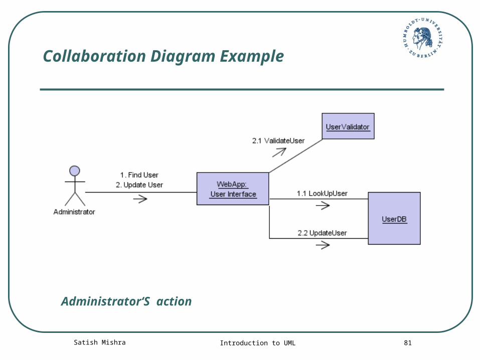
An Administrator using a Web Application to manage a user account. Notice how you can follow the process from object to object, according to the outline below:
1. Find User 1.1 LookUpUser2. Update User 2.1 ValidateUser 2.2 UpdateUser
Satish Mishra Introduction to UML 81
Collaboration Diagram Example
Administrator‘S action
Satish Mishra Introduction to UML 82
Interactation diagram details
Using interaction diagrams, we can clarify the sequence of operation calls among objects used to complete a single use case
Collaborations have the added advantage of interfaces and freedom of layout, but can be difficult to follow, understand and create.
Interaction diagrams are used to diagram a single use case. When you want to examine the behaviour of a single instance over time use a state diagram, and if you want to look at the behaviour of the system over time use an activity diagram.
Satish Mishra Introduction to UML 83
Component diagram
Component diagrams illustrate the organizations and dependencies among software components
A component may be A source code component A run time components or An executable component

Satish Mishra Introduction to UML 84
Component diagramComponent diagram
OrderProcess
CreditCardCharger
CarSeller
OrderManager
ManagerInterface
<<database>>
OrderDB
Client
CreditCardAgent
Manager
Status Purchase
CoordinateCarSale GoodsSale
Satish Mishra Introduction to UML 85
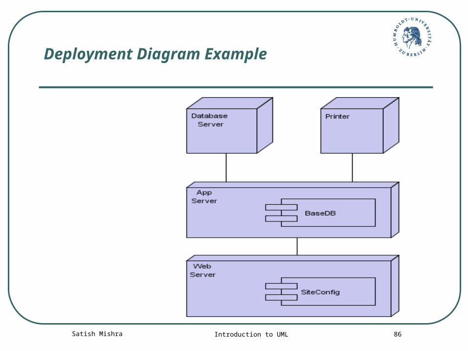
Deployment diagram
The Deployment diagram models the hardware used in implementing a system and the association between those hardware components
The deployment diagram visualizes the distribution of components across the enterprise
Satish Mishra Introduction to UML 86
Deployment Diagram Example
Satish Mishra Introduction to UML 87
Use Case Based Testing (UCBT)
Writing test case from Use case
Test cases that are derived from use cases take advantage of the existing specification to ensure good functional test coverage of the system.
Satish Mishra Introduction to UML 88
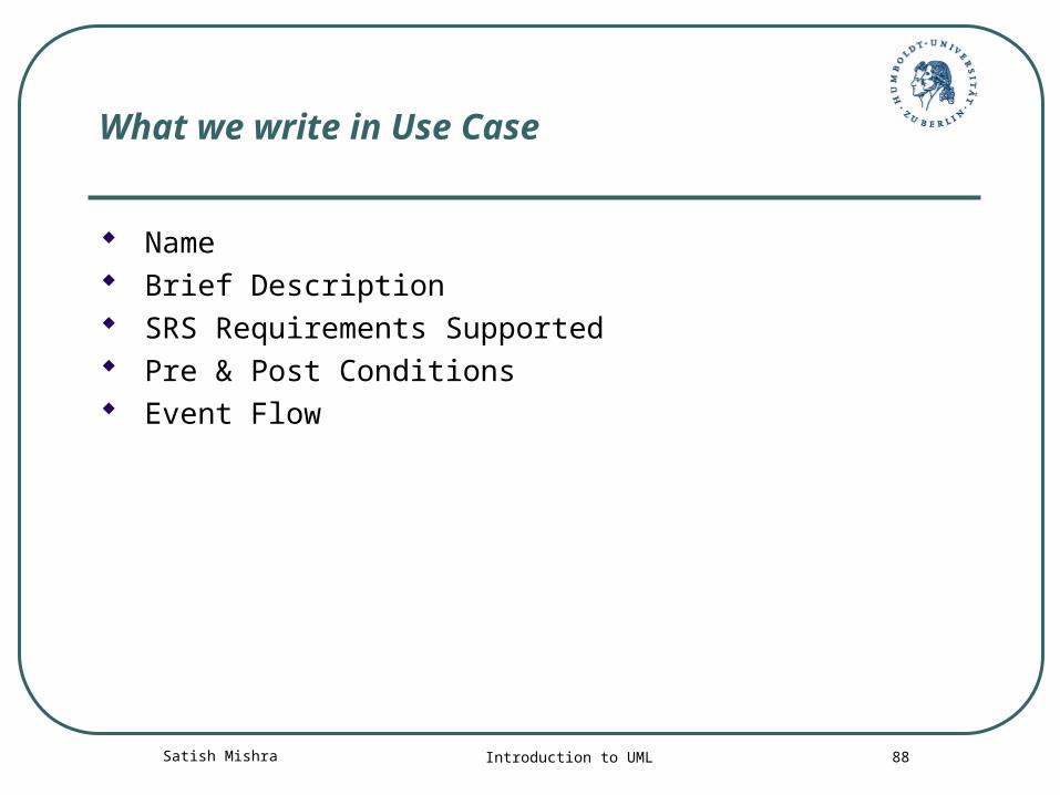
What we write in Use Case
Name Brief Description SRS Requirements Supported Pre & Post Conditions Event Flow
Satish Mishra Introduction to UML 89
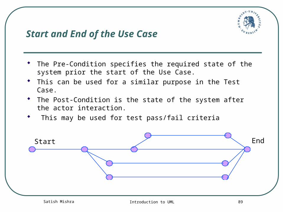
Start and End of the Use Case
The Pre-Condition specifies the required state of the system prior the start of the Use Case.
This can be used for a similar purpose in the Test Case. The Post-Condition is the state of the system after the
actor interaction. This may be used for test pass/fail criteria
Start End
Satish Mishra Introduction to UML 90
UCBT : Example
Monitor and control the normal entry and exit of building occupants through the use of personal security cards. This includes entry and exit of the building proper, and entry and exit from particular security zones within the building. The system controls the locks on the doors, and will not unlock a door unless the appropriate security card is swiped through the card reader by the door
Satish Mishra Introduction to UML 91
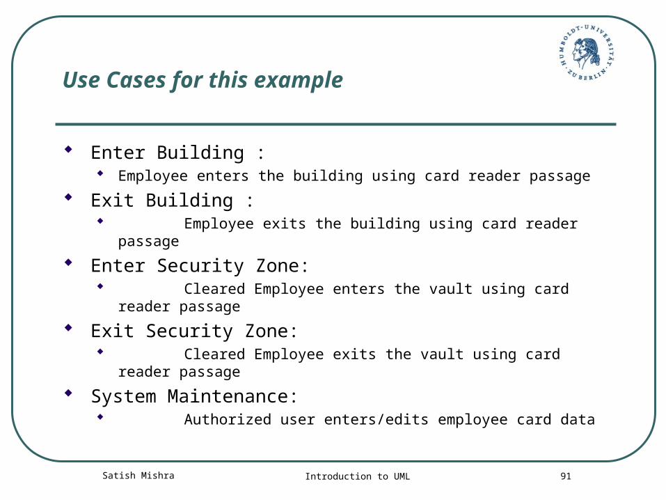
Use Cases for this example
Enter Building : Employee enters the building using card reader passage
Exit Building : Employee exits the building using card reader passage
Enter Security Zone: Cleared Employee enters the vault using card reader
passage
Exit Security Zone: Cleared Employee exits the vault using card reader
passage
System Maintenance: Authorized user enters/edits employee card data
Satish Mishra Introduction to UML 92
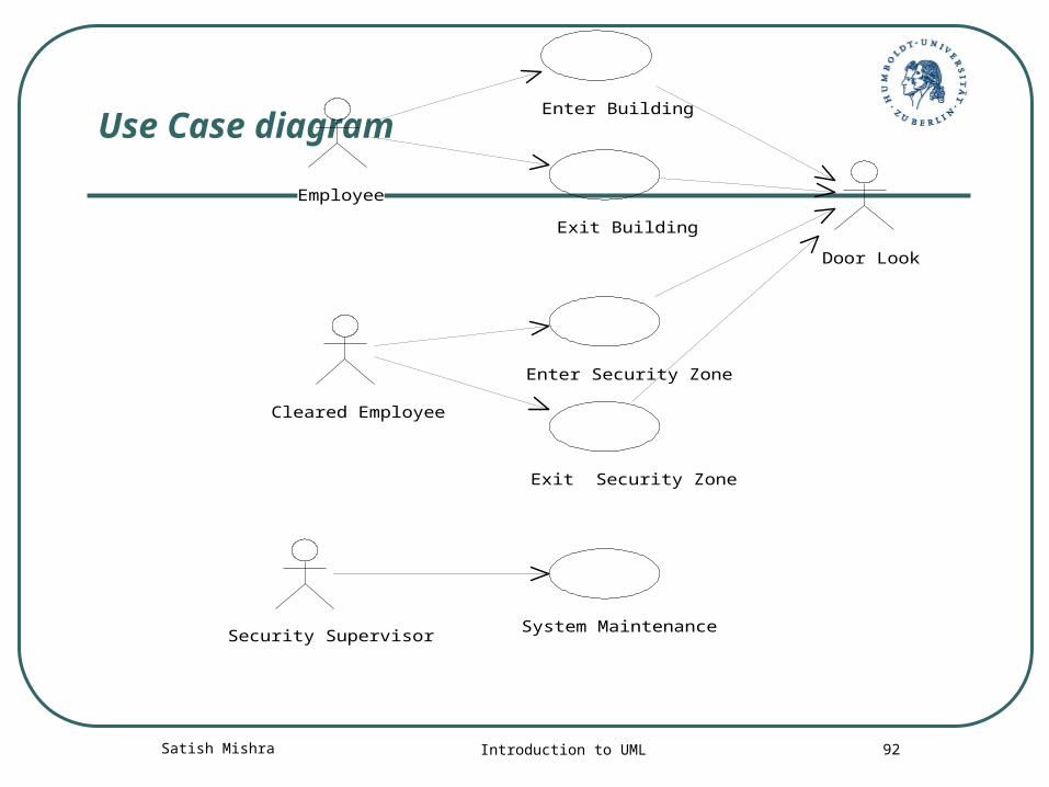
Use Case diagram
Employee
Enter Building
Exit Building
Cleared Employee
Enter Security Zone
Exit Security Zone
Door Look
Security SupervisorSystem Maintenance
Satish Mishra Introduction to UML 93
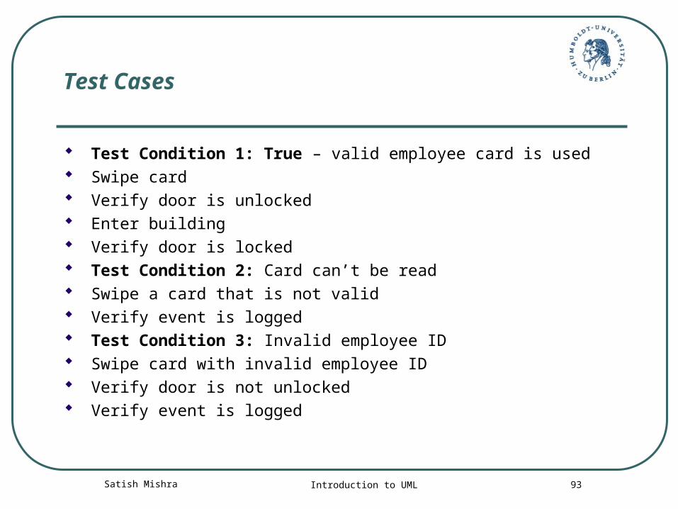
Test Cases
Test Condition 1: True – valid employee card is used Swipe card Verify door is unlocked Enter building Verify door is locked Test Condition 2: Card can’t be read Swipe a card that is not valid Verify event is logged Test Condition 3: Invalid employee ID Swipe card with invalid employee ID Verify door is not unlocked Verify event is logged
Satish Mishra Introduction to UML 94
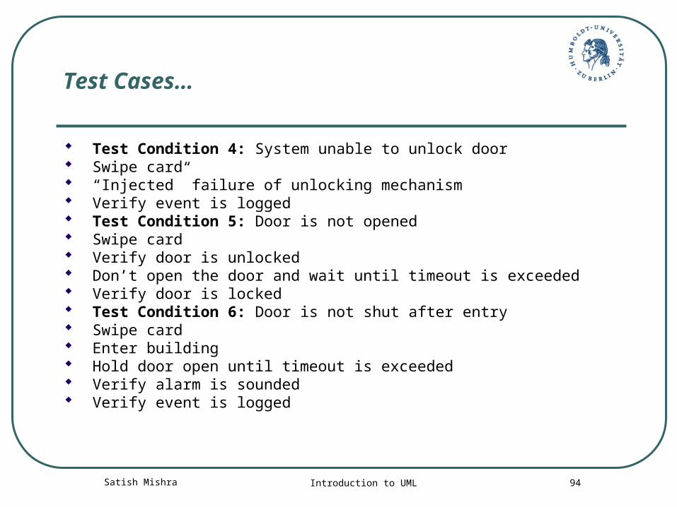
Test Cases…
Test Condition 4: System unable to unlock door Swipe card “Injected” failure of unlocking mechanism Verify event is logged Test Condition 5: Door is not opened Swipe card Verify door is unlocked Don’t open the door and wait until timeout is exceeded Verify door is locked Test Condition 6: Door is not shut after entry Swipe card Enter building Hold door open until timeout is exceeded Verify alarm is sounded Verify event is logged
Satish Mishra Introduction to UML 95
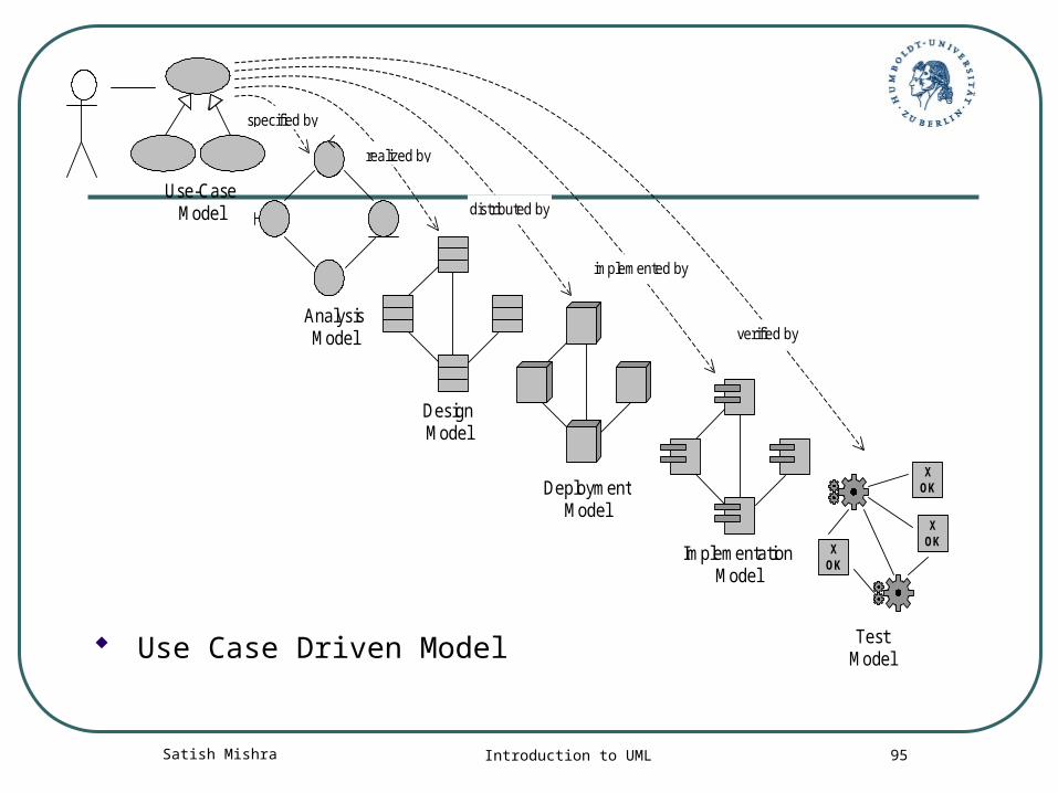
Use-CaseModel
AnalysisModel
DesignModel
DeploymentModel
ImplementationModel
TestModel
XOK
XOK
XOK
specified by
realized by
distributed by
implemented by
verified by
Use Case Driven Model
Satish Mishra Introduction to UML 96