visual feedback balance control of a robot manipulator...
TRANSCRIPT

Journal of Computer and Communications, 2017, 5, 8-18 http://www.scirp.org/journal/jcc
ISSN Online: 2327-5227 ISSN Print: 2327-5219
DOI: 10.4236/jcc.2017.59002 July 3, 2017
Visual Feedback Balance Control of a Robot Manipulator and Ball-Beam System
Ching-Long Shih*, Jung-Hsien Hsu, Chi-Jen Chang
Department of Electrical Engineering, National Taiwan University of Science and Technology, Taiwan
Abstract In this paper, we present a vision guided robotic ball-beam balancing control system, consisting of a robot manipulator (actuator), a ball-beam system (plant) and a machine vision system (feedback). The machine vision system feedbacks real-time beam angle and ball position data at a speed of 50 frames per second. Based on feedback data, the end-effector of a robot manipulator is driven to control the ball position by maneuvering of the inclination angle of the ball-beam system. The overall control system is implemented with two FPGA chips, one for machine vision processing, and one for robot joints servo PID controllers as well as ball position PD controller. Experiments are per-formed on a 5-axes robot manipulator to validate the proposed ball beam ba-lancing control system.
Keywords Ball-Beam System, Robot Manipulator, Vision Feedback Control, PID/PD Control, FPGA
1. Introduction
Machine vision system can be applied in real-time to precisely measure visual properties such as color, length, angle, position, orientation, etc. One advantage of machine vision system is the ability to perform contact-free measurement, which is important especially when contact is difficult. However, one of the dif-ficulties in designing a machine vision system is how to be robust to noises present in an image, to scene disturbances caused by unwanted background and foreground objects, as well as to different illumination conditions. Various ma-chine vision approaches had been applied to visual servo control [1]. Visual ser-vo system must be capable of tracking image features in a sequence of images. Visual object tracking is used to identify the trajectory of moving objects in vid-
How to cite this paper: Shih, C.-L., Hsu, J.-H. and Chang, C.-J. (2017) Visual Feedback Balance Control of a Robot Manipulator and Ball-Beam System. Journal of Computer and Communications, 5, 8-18. https://doi.org/10.4236/jcc.2017.59002 Received: May 21, 2017 Accepted: June 30, 2017 Published: July 3, 2017 Copyright © 2017 by authors and Scientific Research Publishing Inc. This work is licensed under the Creative Commons Attribution International License (CC BY 4.0). http://creativecommons.org/licenses/by/4.0/
Open Access

C.-L. Shih et al.
9
eo frame sequences. Object tracking involves intensive computation in order to extract real-time information from high-volume video data with low power consumption. Real-time image processing tasks require not only high computing power but also high data bandwidth. Thus, prototypical FPGA based real-time image processing systems for computer vision and visual servo applications have been proposed [2] [3] [4]. An application can usually be divided into a pre- processing part located on a dedicated subsystem and a high-level part located on a host system. For instance, the pre-processing system is built on FPGA chips and the high-level part for robot vision applications runs on a PCI-based PC system [2]. In particular, an FPGA implementation of a multi-microrobot visual tracking system using CMOS vision sensors had been shown to achieve a 0.01 mm accuracy [3]. Their system was capable of tracking a single robot at a fre-quency of over 200 Hz. The motivation of this work is to develop a real-time machine vision feedback based robot motion ball-beam balance control system on FPGA chips.
Ball-and-beam control systems are well-known apparatus designed for de-monstrating position control capabilities of unstable open-loop systems. Many nonlinear/linear control methods as well as system stability analysis of ball-beam systems have been presented in literatures [5] [6] [7]. In particular, for a non- linear ball-beam system model, a simple PD controller with asymptotic stability has been theoretically proven and experimentally tested [7]. However, accurately determining the beam angle and ball position in real-time is an important task. There are many approaches to applying beam inclination and ball position sen-sors; visual feedback is a common solution [8] [9] [10]. However, there are only few works for applying visual feedback to both beam inclination and ball posi-tion measurements. Moreover, there are also few works on the integration of a full-scale robot manipulator and vision feedback system in a ball-beam or a ball-plate balancing control system.
Other related works include ball-beam balance systems with feedbacks from a tablet [11] and from a smartphone [12], a robotic soccer beam balance system [13], and a ball-and-plate balance system [14]. A ball-beam control system with visual feedback sensor from a smart tablet had been designed in [11]. Addition-ally, augmented reality was integrated into an interactive touchscreen interface. A ball-beam system with wireless sensors on a smartphone had been demon-strated in [12]. A smartphone’s inertial and camera sensors were used to meas-ure the angular orientation/velocity of the beam and translational ball position, and a local feedback linearizing controller was used to stabilize the ball-beam control system. Ryu and Oh had experimented with a soccer-and-beam balance system installed on the top of the end-effector of a redundant manipulator [13]. A force-torque sensor was attached to the end-effector to estimate the ball position through differentiation. Cheng and Tsai had designed a ball-and-plate balance system, which was attached as the end effector and maneuver by a two-DOF ro-botic wrist [14]. The ball’s position was captured by a PC-based video camera sys-tem and the orientation of the plate was controlled by a LQR algorithm.
C.-L. Shih et al.
10
Up to now, we have not observed that an automatic ball-beam balance system by a robot manipulator with more than 3-axes. This paper attempts to design an automatic robotic ball-beam balance system using an integrated machine vision system. The main goal of this machine vision based robot motion control system is to measure the ball position and beam angle in real-time, and to balance the ball at any desired point on the beam through the motion of a 5-axes robotic end-effector. This works also focuses on an entirely FPGA based control imple-mentation with input from a CMOS image sensor.
2. Robotic Ball-Beam Control System
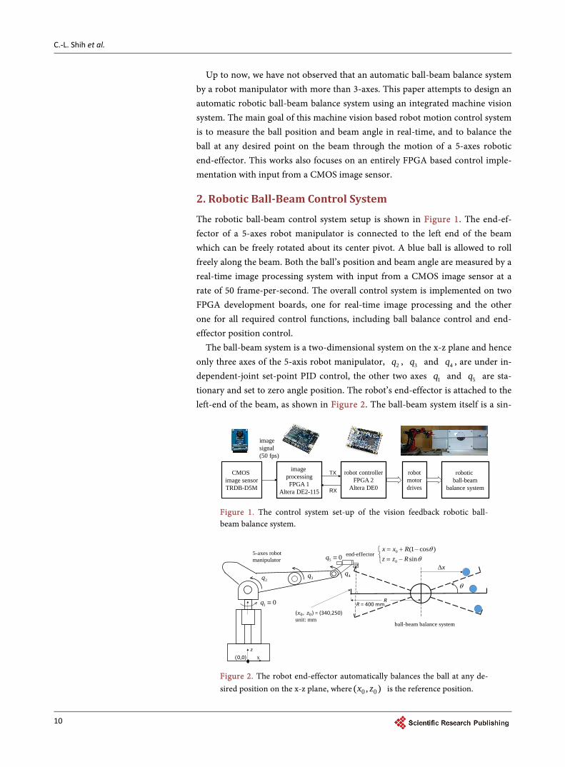
The robotic ball-beam control system setup is shown in Figure 1. The end-ef- fector of a 5-axes robot manipulator is connected to the left end of the beam which can be freely rotated about its center pivot. A blue ball is allowed to roll freely along the beam. Both the ball’s position and beam angle are measured by a real-time image processing system with input from a CMOS image sensor at a rate of 50 frame-per-second. The overall control system is implemented on two FPGA development boards, one for real-time image processing and the other one for all required control functions, including ball balance control and end- effector position control.
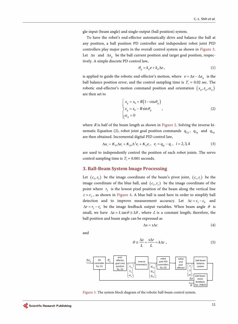
The ball-beam system is a two-dimensional system on the x-z plane and hence only three axes of the 5-axis robot manipulator, 2q , 3q and 4q , are under in-dependent-joint set-point PID control, the other two axes 1q and 5q are sta-tionary and set to zero angle position. The robot’s end-effector is attached to the left-end of the beam, as shown in Figure 2. The ball-beam system itself is a sin-
Figure 1. The control system set-up of the vision feedback robotic ball- beam balance system.
Figure 2. The robot end-effector automatically balances the ball at any de-sired position on the x-z plane, where ),( 00 zx is the reference position.
image processingFPGA 1
Altera DE2-115
robotic ball-beam
balance system
CMOS image sensorTRDB-D5M
imagesignal(50 fps)
TX
RX
robot controllerFPGA 2
Altera DE0
robotmotordrives
(𝑥0, 𝑧0) = (340,250)unit: mm
R
xz
end-effector
R = 400 mm
(0,0)
5-axes robot manipulator
ball-beam balance system
θ
−=−+=
sin)cos1(
0
0
θθ
RzzRxx
2q 3q 4qx∆
01 ≡q
05 ≡q
C.-L. Shih et al.
11
gle-input (beam angle) and single-output (ball position) system. To have the robot’s end-effector automatically drive and balance the ball at
any position, a ball position PD controller and independent robot joint PID controllers play major parts in the overall control system as shown in Figure 3. Let x∆ and gx∆ be the ball current position and target goal position, respec-tively. A simple discrete PD control law,
g p dk e k eθ = + ∆ , (1)
is applied to guide the robotic end-effector’s motion, where ge x x= ∆ − ∆ is the ball balance position error, and the control sampling time is Tc = 0.02 sec. The robotic end-effector’s motion command position and orientation ( ), ,g g gx z α are then set to
( )0
0
1 cos
sin
0
g g
g g
g
x x R
z z R
θ
θ
α
= + − = − =
, (2)
where R is half of the beam length as shown in Figure 2. Solving the inverse ki-nematic Equation (2), robot joint goal position commands 2gq , 3gq and 4gq are then obtained. Incremental digital PID control law,
2i Pi i Di i Ii iu K e K e K e∆ = ∆ + ∆ + , i ig ie q q= − , 2,3,4i = (3)
are used to independently control the position of each robot joints. The servo control sampling time is Ts = 0.001 seconds.
3. Ball-Beam System Image Processing
Let ( )0 0,c r be the image coordinate of the beam’s pivot joint, ( )1 1,c r be the image coordinate of the blue ball, and ( )2 2,c r be the image coordinate of the point where 2r is the lowest pixel position of the beam along the vertical line
2c c= , as shown in Figure 4. A blue ball is used here in order to simplify ball detection and to improve measurement accuracy. Let 1 0c c c∆ = − and
2 0r r r∆ = − be the image feedback output variables. When beam angle θ is small, we have tanz L Lθ θ∆ = ≅ , where L is a constant length; therefore, the ball position and beam angle can be expressed as
x s c∆ = ∆ (4)
and
z s r k rL L
θ∆ ∆
≅ = = ∆ , (5)
Figure 3. The system block diagram of the robotic ball-beam control system.
PDcontroller
Eq. (1)
end-effector
goal cmdpositionEq. (2)
inversekinematics
robotjoint PID
controllers Eq. (3)
ball-beambalance system
ball-beam vision
feedbackEqs. (4)&(5)
gx∆
x∆
gθ
g
g
g
zx
α
g
g
q
qqq
4
3
2
robot and end-
effector
αzx
θ

C.-L. Shih et al.
12
where scaling constant s = 1.5 mm/pixel and k = 0.24 deg/pixel. The proposed ball-beam system visual feedback is built on the Altera DE2
FPGA development board with input from a CMOS image sensor camera (TRDB-D5M). The image processing module captures real-time images with a 640 × 480 resolution and at 50 fps. Figure 5 shows the functional block diagram of image processing module, in which G is the G-component of the RGB color image. The processing pipeline includes color space transformation, Sobel edge detection, binary threshold, erosion/dilation, and target object position detec-tion.
Real-time image input is fed to the FPGA chip row by row. Up to 5 rows of an image are stored in FIFO line-buffers in a pipelined fashion. The image processing unit is clocked at 96 MHz. The raw image data is captured by a color
Figure 4. Ball-beam visual sensor system, where L depends on the distance between the camera and the beam.
Figure 5. The image processing pipeline.
blue ball
beam02 rrr −=∆
r
pixels 237=L
θ
pivot joint
c)0,0(
)479,639(
image coordinate frame
ball-beanequilibriumconfiguration
0r
0c
01 ccc −=∆
2c 1c
2r
Sobel edgedetection
Binary imagethresholding
Dilation
Beam angledetection
RAW to RGB
RGB to Cb
Binary imagethresholding
Erosion and dilation
Blue ballposition detection
CMOS sensor image input
),( 11 rc
Cb
),( 22 rc
GRGB

C.-L. Shih et al.
13
camera with 1280 960× resolution at 50 fps (frames per second). The raw im-age is converted to a 640 480× 24-bit RGB image (by down sampling of every 2 2× scanned pixels). The center position of the blue ball is obtained as follows. First, RGB to bC color space transformation is performed :
0.169 0.331 0.5 128bC R G B= − − + + , where 0 , , 255R G B≤ ≤ and 0 255bC≤ ≤ . Color space transformation is followed by binary segmentation for the bC component with a threshold value of 130. An erosion operation in a 3 3× window is performed next, followed by a dilation operation in a 3 3× window. True pixels indicate potential ball position. Finally, the center of blue ball ( )1 1,c r is calculated from the center of the true pixels. Beam angle detec-tion is processed in a similar way. Since the G-component of the RGB color im-age is similar to the gray image. First, Sobel edge detection is applied to the G-component of the original RGB image with a threshold value of 384, followed by a dilation operation in 3 3× window. For all pixels, 2r is the lowest pixel point of the beam in column 2c ( 2 71c = ) such that
{ }22 ,max : 1,180 340c rr r P r= = ≤ ≤ . Figure 6 shows the ball-beam visual feed-back processing experimental results.
4. Experimental Results 4.1. Robot Joints Set-Point Control Experiments
The robot manipulator is running in set-point position control mode, in which each joint is under independent joint PID servo control. The digital PID control is implemented in relative form
( ) ( ) ( ) ( )( )( ) ( ) ( )( )
1 1
2 1 2i i Ii i Pi i i
Di i i i
u u n K e n K e n e n
K e n e n e n
= − + + − −
+ − − + −
( ) ( )max max
min max
min min
i i i
u u uu n sat u u u u u
u u u
>= = ≤ ≤ <
,
Figure 6. Experimental results of the ball-beam visual feedback processing.
(a) The G component of original image
(b) binary image for ball position detection (c) binary image for beam angle detection
712 =c
=),( 11 rc 180
3402462 =r)297,556(
C.-L. Shih et al.
14
where ( ) ( ) ( )i ig ie n q n q n= − , 2,3,4i = , is the current position error of joint i. PID gains for joint 2, 3 and 4 are 2 60PK = , 2 1IK = , 2 10DK = ( 2q -axis),
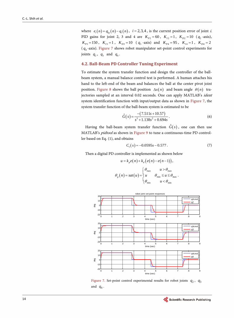
3 150PK = , 3 1IK = , 3 10DK = ( 3q -axis) and 4 95PK = , 4 1IK = , 4 2DK = ( 4q -axis). Figure 7 shows robot manipulator set-point control experiments for joints 2q , 3q and 4q .
4.2. Ball-Beam PD Controller Tuning Experiment
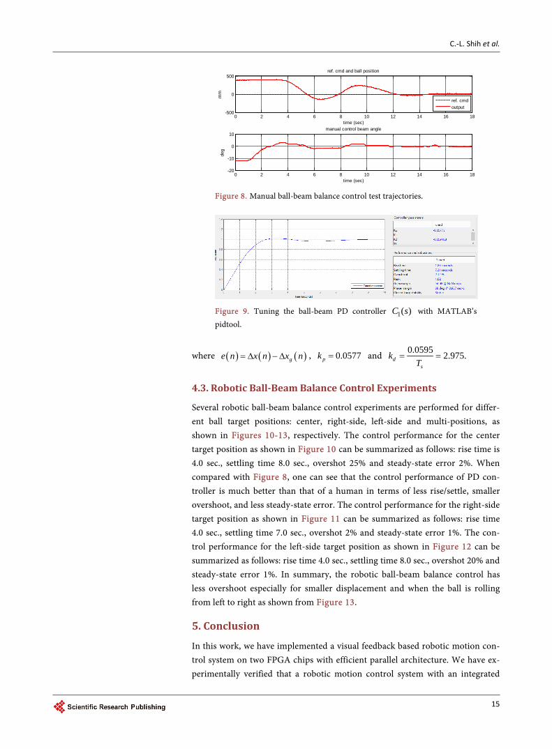
To estimate the system transfer function and design the controller of the ball- beam system, a manual balance control test is performed. A human attaches his hand to the left-end of the beam and balances the ball at the center pivot joint position. Figure 8 shows the ball position ( )x n∆ and beam angle ( )nθ tra-jectories sampled at an interval 0.02 seconds. One can apply MATLAB’s ident system identification function with input/output data as shown in Figure 7, the system transfer function of the ball-beam system is estimated to be
( ) ( )3 2
7.511 10.57ˆ1.138 0.694
sG s
s s s− +
=+ +
. (6)
Having the ball-beam system transfer function ( )G s , one can then use MATLAB’s pidtool as shown in Figure 9 to tune a continuous-time PD control-ler based on Eq. (1), and obtains
( )1 0.0595 0.577C s s= − − . (7)
Then a digital PD controller is implemented as shown below
( ) ( ) ( )( )1p du k e n k e n e n= + − − ,
( ) ( )max max
min max
min min
g
un sat u u u
u
θ θθ θ θ
θ θ
>= = ≤ ≤ <
.
Figure 7. Set-point control experimental results for robot joints 2q , 3q
and 4q .
0 1 2 3 4 5 6 7 8 9-20
-10
0
10
20
deg
time (sec)
robot joint set-point responses
0 1 2 3 4 5 6 7 8 9-20
-10
0
10
20
deg
time (sec)
0 1 2 3 4 5 6 7 8 9-20
-10
0
10
20
deg
time (sec)
q2cmdq2
q3cmdq3
q4cmdq4
C.-L. Shih et al.
15
Figure 8. Manual ball-beam balance control test trajectories.
Figure 9. Tuning the ball-beam PD controller )(1 sC with MATLAB’s pidtool.
where ( ) ( ) ( )ge n x n x n= ∆ − ∆ , 0.0577pk = and 0.0595 2.975.ds
kT
= =
4.3. Robotic Ball-Beam Balance Control Experiments
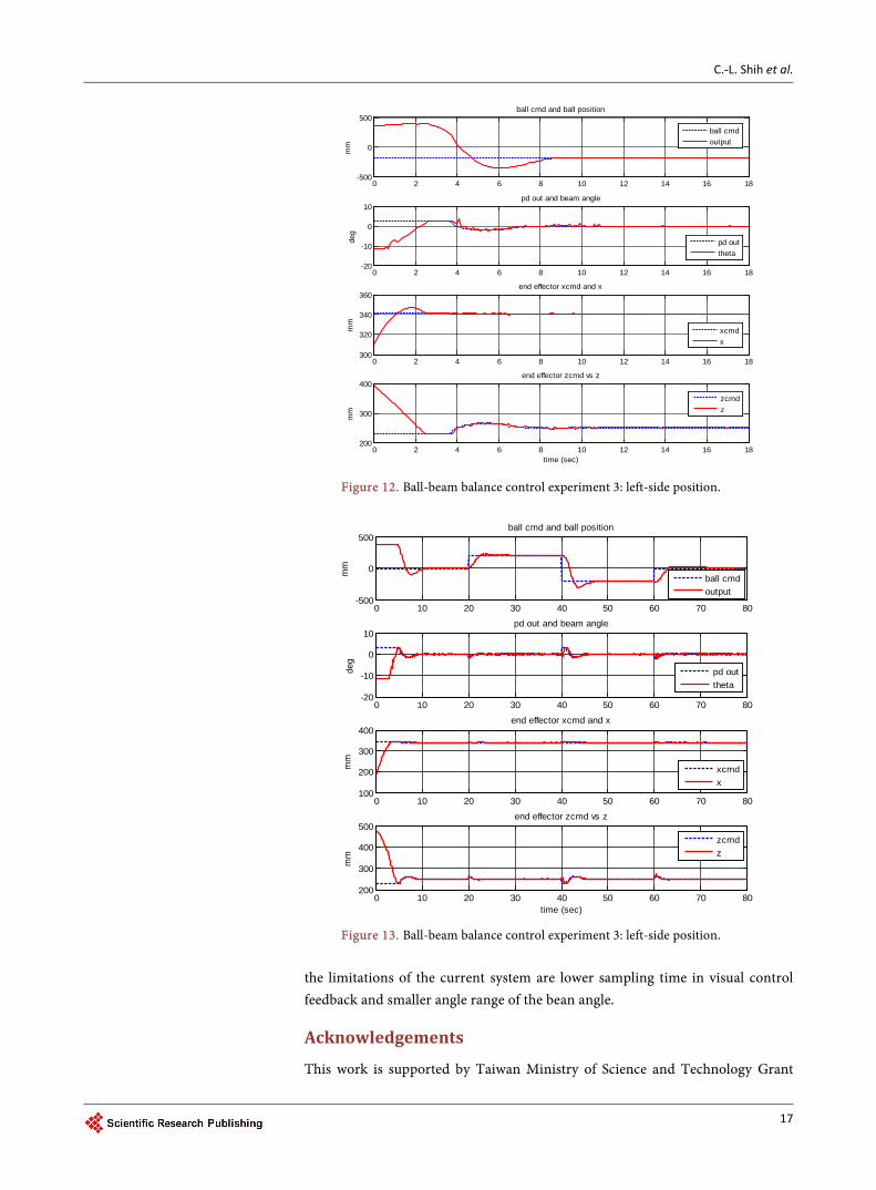
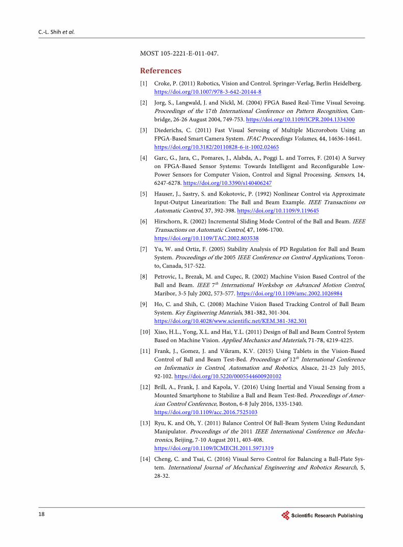
Several robotic ball-beam balance control experiments are performed for differ-ent ball target positions: center, right-side, left-side and multi-positions, as shown in Figures 10-13, respectively. The control performance for the center target position as shown in Figure 10 can be summarized as follows: rise time is 4.0 sec., settling time 8.0 sec., overshot 25% and steady-state error 2%. When compared with Figure 8, one can see that the control performance of PD con-troller is much better than that of a human in terms of less rise/settle, smaller overshoot, and less steady-state error. The control performance for the right-side target position as shown in Figure 11 can be summarized as follows: rise time 4.0 sec., settling time 7.0 sec., overshot 2% and steady-state error 1%. The con-trol performance for the left-side target position as shown in Figure 12 can be summarized as follows: rise time 4.0 sec., settling time 8.0 sec., overshot 20% and steady-state error 1%. In summary, the robotic ball-beam balance control has less overshoot especially for smaller displacement and when the ball is rolling from left to right as shown from Figure 13.
5. Conclusion
In this work, we have implemented a visual feedback based robotic motion con-trol system on two FPGA chips with efficient parallel architecture. We have ex-perimentally verified that a robotic motion control system with an integrated
0 2 4 6 8 10 12 14 16 18-500
0
500ref. cmd and ball position
time (sec)
mm
0 2 4 6 8 10 12 14 16 18-20
-10
0
10manual control beam angle
time (sec)
deg
ref. cmdoutput

C.-L. Shih et al.
16
Figure 10. Ball-beam balance control experiment 1: center position.
Figure 11. Ball-beam balance control experiment 2: right-side position.
visual feedback system can automatically balance a ball-beam system with the end-effector of a 5-axis manipulator. This machine vision based robotic ball- beam set-point control system is able to balance the ball at any desired position on the beam efficiently in real-time. Although the proposed system is almost as good as a naive user manually balancing the ball to stay at any desired position,
0 2 4 6 8 10 12 14 16 18-200
0
200
400ball cmd and ball position
mm
ball cmdoutput
0 2 4 6 8 10 12 14 16 18-20
-10
0
10pd out and beam angle
deg
pd outtheta
0 2 4 6 8 10 12 14 16 18300
320
340
360end effector xcmd and x
mm
xcmdx
0 2 4 6 8 10 12 14 16 18200
300
400end effector zcmd vs z
mm
time (sec)
zcmdz
0 2 4 6 8 10 12 14 16 18100
200
300
400ball cmd and ball position
mm
0 2 4 6 8 10 12 14 16 18-20
-10
0
10pd out and beam angle
deg
0 2 4 6 8 10 12 14 16 18300
320
340
360end effector xcmd and x
mm
0 2 4 6 8 10 12 14 16 18200
300
400
500end effector zcmd vs z
mm
time (sec)
ball cmdoutput
pd outtheta
xcmdx
zcmdz
C.-L. Shih et al.
17
Figure 12. Ball-beam balance control experiment 3: left-side position.
Figure 13. Ball-beam balance control experiment 3: left-side position.
the limitations of the current system are lower sampling time in visual control feedback and smaller angle range of the bean angle.
Acknowledgements
This work is supported by Taiwan Ministry of Science and Technology Grant
0 2 4 6 8 10 12 14 16 18-500
0
500ball cmd and ball position
mm
0 2 4 6 8 10 12 14 16 18-20
-10
0
10pd out and beam angle
deg
0 2 4 6 8 10 12 14 16 18300
320
340
360end effector xcmd and x
mm
0 2 4 6 8 10 12 14 16 18200
300
400end effector zcmd vs z
mm
time (sec)
ball cmdoutput
pd outtheta
xcmdx
zcmdz
0 10 20 30 40 50 60 70 80-500
0
500ball cmd and ball position
mm
ball cmdoutput
0 10 20 30 40 50 60 70 80-20
-10
0
10pd out and beam angle
deg
pd outtheta
0 10 20 30 40 50 60 70 80100
200
300
400end effector xcmd and x
mm
xcmdx
0 10 20 30 40 50 60 70 80200
300
400
500end effector zcmd vs z
mm
time (sec)
zcmdz
C.-L. Shih et al.
18
MOST 105-2221-E-011-047.
References [1] Croke, P. (2011) Robotics, Vision and Control. Springer-Verlag, Berlin Heidelberg.
https://doi.org/10.1007/978-3-642-20144-8
[2] Jorg, S., Langwald, J. and Nickl, M. (2004) FPGA Based Real-Time Visual Sevoing. Proceedings of the 17th International Conference on Pattern Recognition, Cam-bridge, 26-26 August 2004, 749-753. https://doi.org/10.1109/ICPR.2004.1334300
[3] Diederichs, C. (2011) Fast Visual Servoing of Multiple Microrobots Using an FPGA-Based Smart Camera System. IFAC Proceedings Volumes, 44, 14636-14641. https://doi.org/10.3182/20110828-6-it-1002.02465
[4] Garc, G., Jara, C., Pomares, J., Alabda, A., Poggi L. and Torres, F. (2014) A Survey on FPGA-Based Sensor Systems: Towards Intelligent and Reconfigurable Low- Power Sensors for Computer Vision, Control and Signal Processing. Sensors, 14, 6247-6278. https://doi.org/10.3390/s140406247
[5] Hauser, J., Sastry, S. and Kokotovic, P. (1992) Nonlinear Control via Approximate Input-Output Linearization: The Ball and Beam Example. IEEE Transactions on Automatic Control, 37, 392-398. https://doi.org/10.1109/9.119645
[6] Hirschorn, R. (2002) Incremental Sliding Mode Control of the Ball and Beam. IEEE Transactions on Automatic Control, 47, 1696-1700. https://doi.org/10.1109/TAC.2002.803538
[7] Yu, W. and Ortiz, F. (2005) Stability Analysis of PD Regulation for Ball and Beam System. Proceedings of the 2005 IEEE Conference on Control Applications, Toron-to, Canada, 517-522.
[8] Petrovic, I., Brezak, M. and Cupec, R. (2002) Machine Vision Based Control of the Ball and Beam. IEEE 7th International Workshop on Advanced Motion Control, Maribor, 3-5 July 2002, 573-577. https://doi.org/10.1109/amc.2002.1026984
[9] Ho, C. and Shih, C. (2008) Machine Vision Based Tracking Control of Ball Beam System. Key Engineering Materials, 381-382, 301-304. https://doi.org/10.4028/www.scientific.net/KEM.381-382.301
[10] Xiao, H.L., Yong, X.L. and Hai, Y.L. (2011) Design of Ball and Beam Control System Based on Machine Vision. Applied Mechanics and Materials, 71-78, 4219-4225.
[11] Frank, J., Gomez, J. and Vikram, K.V. (2015) Using Tablets in the Vision-Based Control of Ball and Beam Test-Bed. Proceedings of 12th International Conference on Informatics in Control, Automation and Robotics, Alsace, 21-23 July 2015, 92-102. https://doi.org/10.5220/0005544600920102
[12] Brill, A., Frank, J. and Kapola, V. (2016) Using Inertial and Visual Sensing from a Mounted Smartphone to Stabilize a Ball and Beam Test-Bed. Proceedings of Amer-ican Control Conference, Boston, 6-8 July 2016, 1335-1340. https://doi.org/10.1109/acc.2016.7525103
[13] Ryu, K. and Oh, Y. (2011) Balance Control Of Ball-Beam System Using Redundant Manipulator. Proceedings of the 2011 IEEE International Conference on Mecha-tronics, Beijing, 7-10 August 2011, 403-408. https://doi.org/10.1109/ICMECH.2011.5971319
[14] Cheng, C. and Tsai, C. (2016) Visual Servo Control for Balancing a Ball-Plate Sys-tem. International Journal of Mechanical Engineering and Robotics Research, 5, 28-32.

Submit or recommend next manuscript to SCIRP and we will provide best service for you:
Accepting pre-submission inquiries through Email, Facebook, LinkedIn, Twitter, etc. A wide selection of journals (inclusive of 9 subjects, more than 200 journals) Providing 24-hour high-quality service User-friendly online submission system Fair and swift peer-review system Efficient typesetting and proofreading procedure Display of the result of downloads and visits, as well as the number of cited articles Maximum dissemination of your research work
Submit your manuscript at: http://papersubmission.scirp.org/ Or contact [email protected]