visual design versus development: a case - citeseer
TRANSCRIPT

VISUAL DESIGN VERSUS DEVELOPMENT:A CASE STUDY PRESENTING HOW XML AND XSLT CAN SEPARATE
PRESENTATION FROM DATA
By
DEEPA R. NAIR
A THESIS PRESENTED TO THE GRADUATE SCHOOLOF THE UNIVERSITY OF FLORIDA IN PARTIAL FULFILLMENT
OF THE REQUIREMENTS FOR THE DEGREE OFMASTER OF SCIENCE
UNIVERSITY OF FLORIDA
2001

Copyright 2001
by
DEEPA R. NAIR
iii
ACKNOWLEDGMENTS
First, I would like to thank my advisor, Dr. Doug Dankel, for his guidance
throughout my thesis research. I especially want him to know that I recognize and
appreciate his efforts to make time for me. I would also like to thank the other members
of my committee, Dr. Manuel Bermudez and Dr. Joe Wilson.
The research and project work I did would not have been possible without the
resources provided to me by Barr Systems, Inc. I would like to express my appreciation
to Mr. Tony Barr for giving me this opportunity. I am extremely grateful to Mr. Steve
Scovill, the product development manager at Barr Systems, who served as my technical
advisor. He provided me with insight and encouragement throughout my thesis
development. A thank you also goes out to Ms. Michele Nylander, the technical writing
supervisor, for her comments and suggestions.
To my parents, P.K. and Vimala Nair, I owe a special thank you. They served, as
always, as my biggest motivators and supporters. My sisters, Bindu and Rekha Nair, and
my brother-in-law, Rajiv Suri, receive particular recognition for their constant good vibes
and cheerleading.
Finally, I would like to thank all my friends – both those at work and at school –
for ameliorating my graduate experience.
iv
TABLE OF CONTENTS
page
ACKNOWLEDGMENTS.................................................................................................. iii
LIST OF TABLES ............................................................................................................vii
LIST OF FIGURES..........................................................................................................viii
ABSTRACT........................................................................................................................ x
CHAPTERS
1 INTRODUCTION.......................................................................................................... 11.1. Introduction to the Case Study................................................................................. 11.2. The Problem............................................................................................................. 21.3. The Solution............................................................................................................. 31.4. Summary and What is Next..................................................................................... 6
2 LITERATURE REVIEW AND BACKGROUND: XML AND BARR SYSTEMS .... 72.1. XML ........................................................................................................................ 7
2.1.1. Background ...................................................................................................... 72.1.2. The Language................................................................................................... 82.1.3. The XML Hype .............................................................................................. 102.1.4. Style Sheets .................................................................................................... 112.1.5. XSL Transformations..................................................................................... 112.1.6. SAX and DOM: Programmatic Interfaces ..................................................... 122.1.7. Discussion and Conclusions........................................................................... 13
2.2. Barr Systems.......................................................................................................... 132.2.1. An Introduction .............................................................................................. 132.2.2. RJE Configuration Utility .............................................................................. 142.2.3. The Commands Tab: The Case Study............................................................ 15
2.2.3.1. Sets.......................................................................................................... 152.2.3.2. Description.............................................................................................. 162.2.3.3. Command................................................................................................ 172.2.3.4. Options.................................................................................................... 17
2.3. Summary and What is Next................................................................................... 17
3 THE BIG PICTURE..................................................................................................... 193.1. Proposed Solution.................................................................................................. 19
v
3.2. The Registry........................................................................................................... 203.2.1. Using the Windows Registry.......................................................................... 203.2.2. Format of the Barr Registry ........................................................................... 22
3.3. System Setup ......................................................................................................... 233.3.1. Jakarta-Tomcat ............................................................................................... 233.3.2. Cocoon: A Web-publishing framework ......................................................... 25
3.4. Summary and What is Next................................................................................... 26
4 CONVERSION ENGINE ............................................................................................ 274.1. Registry to XML.................................................................................................... 27
4.1.1. Formatting the Barr RJE.XML File ............................................................... 284.1.2. Rendering a Well-formed XML Document ................................................... 294.1.3. Generic Data Conversion ............................................................................... 304.1.4. Specific Data Conversion: Meta-data DLL.................................................... 31
4.2. Cocoon and XSLT Processing............................................................................... 334.2.1. Template Matching ........................................................................................ 344.2.2. The Barr RJE.XSL File .................................................................................. 34
4.3. Web Browser to Registry: CGIREG...................................................................... 394.3.1. CGI................................................................................................................. 394.3.2. The Meta-data DLL in CGIREG.................................................................... 414.3.3. Document Object Module using MSXML..................................................... 434.3.4. Analysis of System Solution .......................................................................... 46
4.4. Summary and What is Next................................................................................... 46
5 ENHANCEMENTS AND CONCLUSIONS............................................................... 475.1. Complete System................................................................................................... 47
5.1.1. High-level Modifications ............................................................................... 485.1.2. Low-level Modifications ................................................................................ 495.1.3. Remotablity .................................................................................................... 49
5.2. Extendible System ................................................................................................. 515.2.1. Varying Input and Output .............................................................................. 515.2.2. Security........................................................................................................... 51
5.3. Conclusions............................................................................................................ 525.3.1. From MFC to Web Browser........................................................................... 525.3.2. The Perfect Solution? ..................................................................................... 535.3.3. Final Word on Usability................................................................................. 545.3.4. Summary ........................................................................................................ 55
GLOSSARY...................................................................................................................... 56
APPENDICES
A CODE FRAGMENTS FOR REGXML PROJECT .................................................... 60
B CODE FRAGMENTS FOR BARRRJE.XML............................................................ 66
C CODE FRAGMENTS FOR CGIREG PROJECT ...................................................... 74
vi
D CODE FRAGMENTS FOR BARRRJE.XSL FILE.................................................... 78
E CODE FRAGMENTS FROM BARRRJE.DLL.......................................................... 80
LIST OF REFERENCES .................................................................................................. 85
BIOGRAPHICAL SKETCH............................................................................................. 86
vii
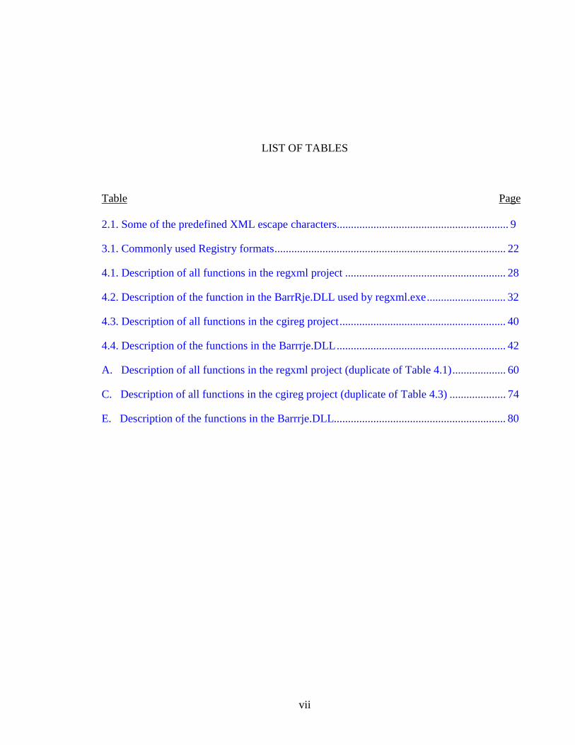
LIST OF TABLES
Table Page
2.1. Some of the predefined XML escape characters............................................................. 9
3.1. Commonly used Registry formats.................................................................................. 22
4.1. Description of all functions in the regxml project ......................................................... 28
4.2. Description of the function in the BarrRje.DLL used by regxml.exe............................ 32
4.3. Description of all functions in the cgireg project........................................................... 40
4.4. Description of the functions in the Barrrje.DLL............................................................ 42
A. Description of all functions in the regxml project (duplicate of Table 4.1)................... 60
C. Description of all functions in the cgireg project (duplicate of Table 4.3) .................... 74
E. Description of the functions in the Barrrje.DLL............................................................. 80
viii
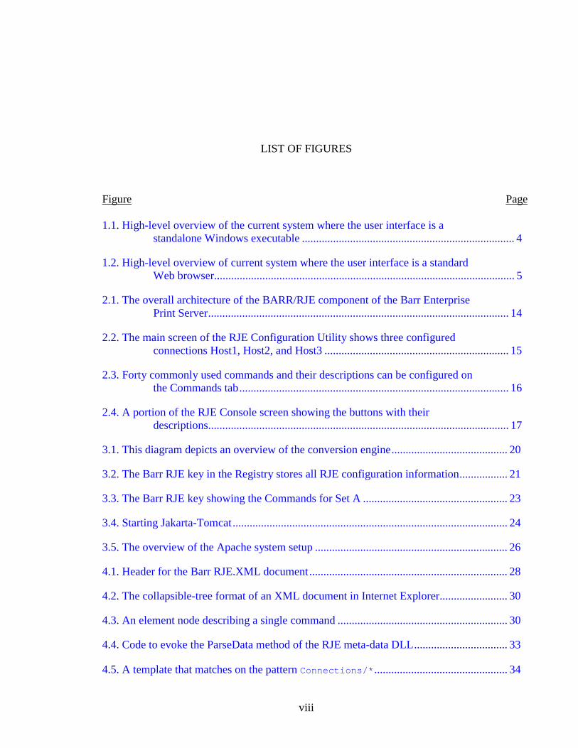
LIST OF FIGURES
Figure Page
1.1. High-level overview of the current system where the user interface is astandalone Windows executable ........................................................................... 4
1.2. High-level overview of current system where the user interface is a standardWeb browser........................................................................................................... 5
2.1. The overall architecture of the BARR/RJE component of the Barr EnterprisePrint Server.......................................................................................................... 14
2.2. The main screen of the RJE Configuration Utility shows three configuredconnections Host1, Host2, and Host3 ................................................................. 15
2.3. Forty commonly used commands and their descriptions can be configured onthe Commands tab............................................................................................... 16
2.4. A portion of the RJE Console screen showing the buttons with theirdescriptions.......................................................................................................... 17
3.1. This diagram depicts an overview of the conversion engine......................................... 20
3.2. The Barr RJE key in the Registry stores all RJE configuration information................. 21
3.3. The Barr RJE key showing the Commands for Set A ................................................... 23
3.4. Starting Jakarta-Tomcat................................................................................................. 24
3.5. The overview of the Apache system setup .................................................................... 26
4.1. Header for the Barr RJE.XML document...................................................................... 28
4.2. The collapsible-tree format of an XML document in Internet Explorer........................ 30
4.3. An element node describing a single command ............................................................ 30
4.4. Code to evoke the ParseData method of the RJE meta-data DLL................................. 33
4.5. A template that matches on the pattern Connections/*............................................... 34
x
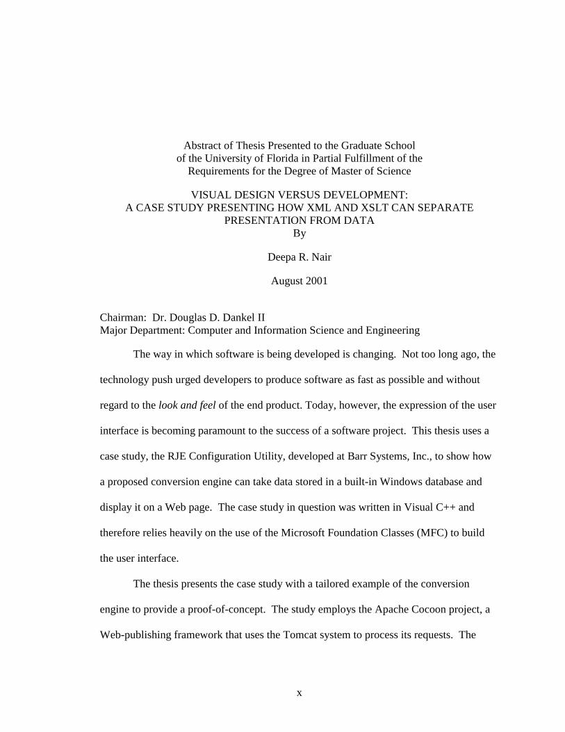
Abstract of Thesis Presented to the Graduate Schoolof the University of Florida in Partial Fulfillment of the
Requirements for the Degree of Master of Science
VISUAL DESIGN VERSUS DEVELOPMENT:A CASE STUDY PRESENTING HOW XML AND XSLT CAN SEPARATE
PRESENTATION FROM DATABy
Deepa R. Nair
August 2001
Chairman: Dr. Douglas D. Dankel IIMajor Department: Computer and Information Science and Engineering
The way in which software is being developed is changing. Not too long ago, the
technology push urged developers to produce software as fast as possible and without
regard to the look and feel of the end product. Today, however, the expression of the user
interface is becoming paramount to the success of a software project. This thesis uses a
case study, the RJE Configuration Utility, developed at Barr Systems, Inc., to show how
a proposed conversion engine can take data stored in a built-in Windows database and
display it on a Web page. The case study in question was written in Visual C++ and
therefore relies heavily on the use of the Microsoft Foundation Classes (MFC) to build
the user interface.
The thesis presents the case study with a tailored example of the conversion
engine to provide a proof-of-concept. The study employs the Apache Cocoon project, a
Web-publishing framework that uses the Tomcat system to process its requests. The
conversion engine uses eXtensible Markup Language (XML) and its associated style
sheets to abstract the data from its presentation. First, configuration information is read
from the Windows Registry, a global storage area, and converted into an XML format.
The conversion process uses meta-data dynamic linked libraries (DLLs) to populate the
information into the schema in a logical format that fits within XML guidelines. After
the XML schema is created, the Cocoon environment invokes XSLT processing to select
specific information and then renders it on a Web browser. Once the user submits
changes to the HTML forms, a CGI script extracts the data. The meta-data DLL is re-
invoked and reformats the information following the conventions set by the software
project. The data are then saved back out to the Registry.
The purpose of the case study is to show how an existing system can be
manipulated to achieve a division between the data and its presentation. The
implementation of such a system is especially desirable in the case of a highly integrated
legacy software project. With information being stored in an XML format and queried
with XSLT, changes can be made to the user interface using straightforward HTML. By
creating the abstraction suggested by the conversion engine, the separated data and
presentation can be managed at a much higher level. The design of the user experience
can consequently be done independently of the information processing, thus allowing for
a more modular and therefore more flexible solution.
1
CHAPTER 1INTRODUCTION
Trends in software design are changing just as fast as the technology on which the
software is based. In the past, a fully functional code base adequately met user
expectations. Today, as presentation and usability issues are surfacing, it is becoming
increasingly important to keep up with the interests and needs of software end users. One
of the concerns of software developers today is what to do with both legacy and current
code to mold them into something that complies with usability standards. As explained
by Virginia Howlett in her book Visual Interface Design for Windows, “Only a few years
ago, software could be sold completely on technical features, but today customers
demand features and flash, and the design of the interface can be the deciding factor in a
purchase” [How96, p. 7]. In the form of a case study, this thesis explores one strategy for
achieving a division between data and presentation – a division that might be the first
stepping stone toward the creation of a more user-friendly product.
1.1. Introduction to the Case Study
Barr Systems, Inc., Gainesville, Florida develops and distributes enterprise-wide
print management solutions. Its newest product is written in Microsoft Visual C++ using
the Microsoft Foundation Classes (MFC) libraries for the Microsoft Windows NT and
2000 operating systems. The Barr Enterprise Print Server has been developed as a
product that facilitates host connectivity from all printing sources. A subset of this
solution is the Remote Job Entry (RJE) print management solution. The RJE

2
Configuration Utility is a standalone MFC application that presents users with the
opportunity to enter several screens of configuration information. The code is highly
integrated, so the user interface design and implementation details are one and the same.
To illustrate the problem with the current integrated nature of data and presentation, parts
of the RJE Configuration Utility are reviewed. Those segments will be converted to a
more modular and therefore more flexible solution.
1.2. The Problem
A definition of the problem can start with an explanation of the cause. In the
years that Windows technology became increasingly predominant, so did the need for
programmers to have viable methods to create the user interface. The MFC library is an
"application framework" for programming in the Windows environment. MFC is written
in C++ and it provides object-oriented wrappers for managing windows, menus, and
dialog boxes [Pro99]. Although this technology was created with the notion of
facilitating the creation of windows, it relies heavily on the creator’s knowledge of both
the data and the presentation. The developer thus becomes both a programmer and a
graphic design artist.
Coding styles and standards are changing as new software development
procedures are being integrated into the current development lifecycle. Usability testing
is now being incorporated into the design phase. One of the biggest problems with
current user-interface design is that the people tasked with the interface creation often
have impressive technical knowledge and skill but lack the necessary creative know-how
to produce a well-designed interface. As Alan Cooper expresses in his book The Inmates
are Running the Asylum, “We often see products that look really good – whose aesthetics

3
are superb – but whose functionality or whose interactivity isn’t adequate” [Coo99, p.
214]. The ideal interface gives the user a pleasant experience. A strategic combination
of aesthetics and functional design determine the product’s usability [How96].
Everything from color choice to layout can affect the functional design. Therefore, it
seems only fitting that people with the necessary skill are tasked with this creative
process.
Anyone experiencing development in a real world environment understands that
as idealistic as notions of software development might be, reality is far different. Code,
although intended to be modularized, is often highly integrated and the notion of any
molding is far more comparable to life-threatening surgery than to any minor task. So, it
is with the intent of separating data and presentation that the following thesis was
instigated. It is important to determine what can be done to fix the current situation. One
suggested means is to create an engine that can facilitate the separation of the data and
presentation. This engine would serve as a process that would allow data abstraction
without massive code changes. What is the means for this process?
1.3. The Solution
The answer is XML. XML stands for eXtensible Markup Language and it is
often described as a meta-markup language. Unlike Hypertext Markup Language
(HTML) and its other predecessors, the extensible nature of XML provides the flexibility
that is a welcomed accessory to a markup language. Another one of the most obvious
advantages of XML is that it is a self-describing language that expresses the structure of
the data and not its presentation. Best of all, any data can be molded into its own XML
4
format, regardless of nature or content. The power of this new technology does not lie
solely in the XML but in the combination of XML and its style sheets.
Now that the problem has been stated and a potential technology solution has
been introduced, here is a presentation of the actual solution. All information, once
configured using the RJE Configuration Utility, is written to the NT (or Windows 2000)
Registry. “The Registry plays a key role in the configuration and control of Windows
[NT and] 2000 system[s]. It is the repository for both system-wide and per-user settings”
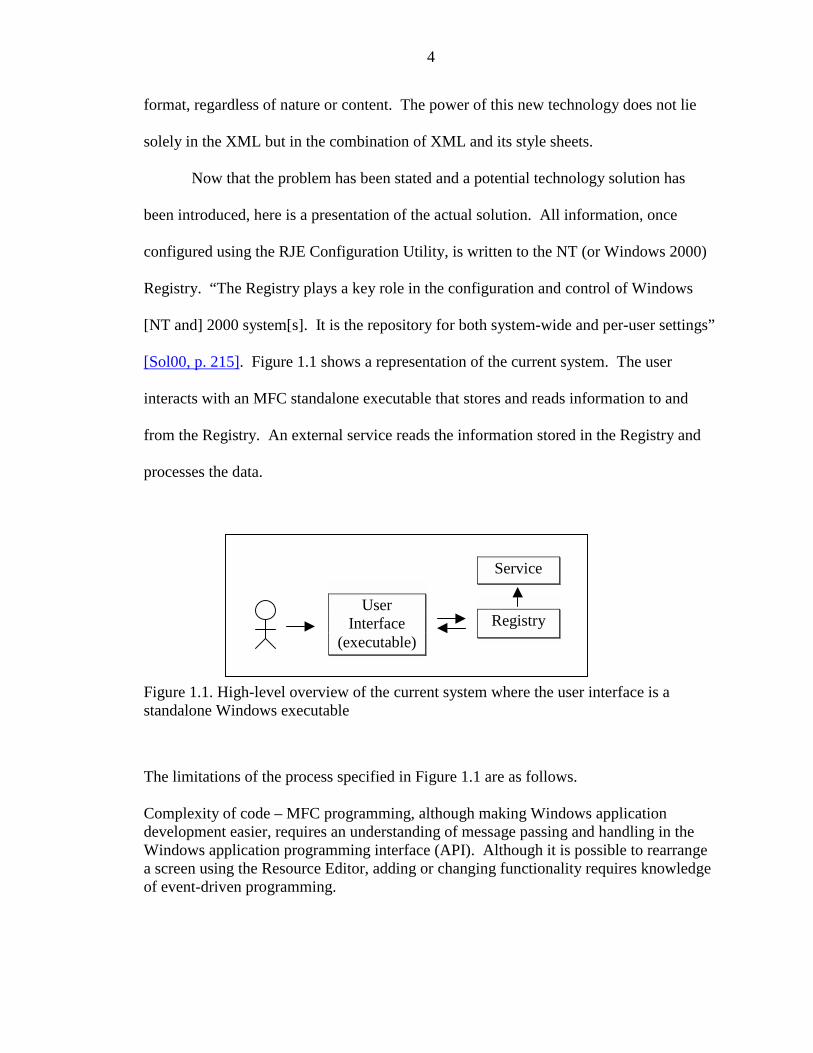
[Sol00, p. 215]. Figure 1.1 shows a representation of the current system. The user
interacts with an MFC standalone executable that stores and reads information to and
from the Registry. An external service reads the information stored in the Registry and
processes the data.
Figure 1.1. High-level overview of the current system where the user interface is astandalone Windows executable
The limitations of the process specified in Figure 1.1 are as follows.
Complexity of code – MFC programming, although making Windows applicationdevelopment easier, requires an understanding of message passing and handling in theWindows application programming interface (API). Although it is possible to rearrangea screen using the Resource Editor, adding or changing functionality requires knowledgeof event-driven programming.
UserInterface
(executable)Registry
Service
5
Difficulty of access – Since the end program is a standalone executable, it must exist inits entirety on the computer that the user wishes to access.
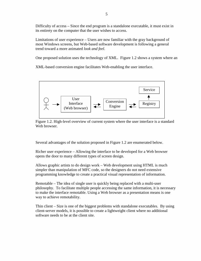
Limitations of user experience – Users are now familiar with the gray background ofmost Windows screens, but Web-based software development is following a generaltrend toward a more animated look and feel.
One proposed solution uses the technology of XML. Figure 1.2 shows a system where an
XML-based conversion engine facilitates Web-enabling the user interface.
Figure 1.2. High-level overview of current system where the user interface is a standardWeb browser.
Several advantages of the solution proposed in Figure 1.2 are enumerated below.
Richer user experience – Allowing the interface to be developed for a Web browseropens the door to many different types of screen design.
Allows graphic artists to do design work – Web development using HTML is muchsimpler than manipulation of MFC code, so the designers do not need extensiveprogramming knowledge to create a practical visual representation of information.
Remotable – The idea of single user is quickly being replaced with a multi-userphilosophy. To facilitate multiple people accessing the same information, it is necessaryto make the interface remotable. Using a Web browser as a presentation means is oneway to achieve remotability.
Thin client – Size is one of the biggest problems with standalone executables. By usingclient-server models, it is possible to create a lightweight client where no additionalsoftware needs to be at the client site.
UserInterface
(Web browser)Registry
Service
ConversionEngine
6
1.4. Summary and What is Next
In summary, this chapter introduces the problem of integrated logic and
presentation via a case study. The following chapters explain the proposed conversion
engine and describe the technologies used to create it. Chapter 2 presents a technical
introduction to XML and other technologies in the form of a literature review. It also
covers a more detailed explanation of the RJE Configuration Utility and the data it
contains. Chapters 3 and 4 present a user view and technical implementation of the
conversion engine. Finally, Chapter 5 is comprised of a summary, conclusions, and some
future enhancements.
7
CHAPTER 2LITERATURE REVIEW AND BACKGROUND: XML AND BARR SYSTEMS
This chapter is divided into two main sections. The first section provides an
overview of XML and introduces the main concepts and language formats that are used
in this thesis. The second section of this chapter provides some background to Barr
Systems and then develops an explanation of the case study, the RJE Configuration
Utility.
2.1. XML
2.1.1. Background
Extensible Markup Language (XML) was introduced by the World Wide Web
Consortium (W3C) as a meta-markup language. The term meta-markup suggests that
XML is more than a standard markup language. Unlike HTML, where a standard set of
tags is supplied, XML is written to suit the data that it is representing. The XML
programmer can generate the tags used to describe the information. Thus, the power of
XML lies in its simple yet extensible nature.
One of the features stressed by most literature on XML is that it is a self-
describing language. Without detailed knowledge of the format of any other type of file,
it is nearly impossible to interpret it. With a well-written XML document, however, a
scan of the data is sufficient to give the reader an approximate understanding of what is
being described. For example, the use of <author></author>, <title></title>, and
8
<publisher></publisher> tags would suggest that the XML file is describing a book.
The next section provides specifics about XML as a language.
2.1.2. The Language
As a tag-based language, XML can encode data in multiple ways. Although there
might be cases where a particular style is more suited, there may not necessarily be a
right and wrong way of specifying information. All information can be specified using
tags, but sometimes it is more useful to make use of attributes. Attributes are name/value
pairs associated with an element. They are defined within the element tag and are
specified following an equal sign and within quotes, such as <author fname=“John”
lname=“doe”></author>. In this example, the name/value pairs are fname/John and
lname/Doe. Documentation on XML suggests that one way to differentiate an
appropriate use of attributes from elements is that elements are used to describe the data,
while attributes are used to describe the meta-data [Har99]. Empty elements are those
that do not have data. The start and end tags can be merged to one tag with a slash at the
end, such as <author fname=“John” lname=“doe”/> [Mar00].
A comparison of XML to HTML shows that XML is a much stricter language.
The language was intentionally designed to adopt a strict syntax to ameliorate the speed
of interpretation by browsers. Studies have shown that more than 50% of code handled
by browsers is for error handling and recovery [Mar00]. “The key to understanding
XML is that the structure of a document is the foundation from which the appearance is
deduced ” [Mar00, p. 13]. At the very minimum, an XML file is required to be well
formed. Some specific requirements for well-formed documents are enumerated below
[Har99]. Certain requirements are described later in more detail.
9
• The document must begin with an XML declaration.
• Elements with data require both a start and end tag.
• Elements without data that use only a single tag must end with a “/>.”
• The document must contain exactly one element (the root), which contains all otherelements.
• Elements may not overlap, but they may be nested.
• Attributes must be in quotes.
• XML tags are case sensitive and cannot be specified with spaces.
To avoid the clutter of interpreting malformed documents, XML specifications actually
prohibit parsers from trying to interpolate the intended meaning of the XML code.
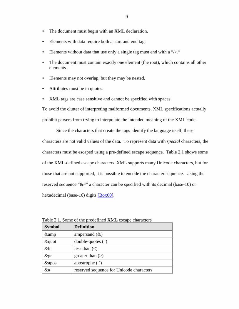
Since the characters that create the tags identify the language itself, these
characters are not valid values of the data. To represent data with special characters, the
characters must be escaped using a pre-defined escape sequence. Table 2.1 shows some
of the XML-defined escape characters. XML supports many Unicode characters, but for
those that are not supported, it is possible to encode the character sequence. Using the
reserved sequence “&#” a character can be specified with its decimal (base-10) or
hexadecimal (base-16) digits [Box00].
Table 2.1. Some of the predefined XML escape charactersSymbol Definition& ampersand (&)" double-quotes (“)< less than (<)&gr greater than (>)&apos apostrophe ( ‘)&# reserved sequence for Unicode characters
10
For the case in which the data contains many foreign characters, it is not practical
to escape all values. Any information that should not be processed by the XML parser
can be stored in a CDATA section. These sections are specified by “<[CDATA [data
goes here]]> ” [Mar00]. Another common use of CDATA sections is if the data itself is
specified in XML.
XML is growing as a language, with various features being added to make it more
robust. Document type definitions (DTDs) are used to declare definitions for the format
of the XML document. Another such feature is the XML Schema, which is an XML
document that contains information about elements and attribute lists. Unlike a DTD, an
XML Schema is based on types and not the tags which makes it more adaptable to
existing programming languages [Box00]. One of the advantages of these features is that
with DTDs or Schemas the data and structure can be validated before the application
starts processing. Neither DTDs nor Schemas are used in this thesis.
2.1.3. The XML Hype
As with many new technologies, it suddenly seems that XML has become the
solution to many problems. The difficulty, however, is determining if it is the correct
solution for the given problem.
XML has replaced Java, Design Patterns, and Object Technology as the softwareindustry’s solution to world hunger. The trade press has anointed XML as theuniversal duct tape for all software integration problems and the large vendorshappily support this vision by integrating XML into everything including databaseengines, development tools, Web browsers, and operating systems. [Box00, p.xiii]
There are two views of XML: the document view and the data view. The
document-view suggests that the purpose of XML is to specify the format and
presentation of the data. The data-view suggests that XML is a new format that can be
11
used to store data in an easy-to-parse format. Regardless of the approach taken by the
XML creator, the power of this technology lies in its association with style sheets and
transforms [Box00].
2.1.4. Style Sheets
Style sheets and XML documents used in conjunction make a powerful team.
While an XML document contains the data, the style sheet specifies how the documents
should be rendered on the output device, regardless of whether it is the screen or paper.
Currently, there are two types of style sheets supported by XML, Cascading Style Sheet
(CSS) and eXtensible Stylesheet Language (XSL). Of the two, XSL is much more
powerful, while CSS is more widespread [Mar00]. Since XSL is used in this thesis, it is
covered in more detail.
XSL is composed of two parts, a transformation language and a formatting
language. The transformation language defines rules in the form of elements, describing
how one XML document can be transformed into another. The formatting half can be
used to render the document into other formats such as PDF. The two parts of the XSL
language can be used independently of each other [Har99].
2.1.5. XSL Transformations
When I first saw the XSL Transformation language, XSLT, I realized that thiswas going to be the SQL of the Web, the high-level data manipulation languagethat would turn XML from being merely a storage and transmission format fordata into an active information source that could be queried and manipulated in aflexible, declarative way. [Kay00, p. 1]
XSLT stands for eXtensible Stylesheet Language: Transformations. Its definition
suggests that it is used for transformation from one XML document to another. But, it is
actually very useful for transforming an XML document into HTML. It is this capability
of XSLT that makes it useful for this thesis. In a discussion of the need to transform
12
XML, Michael Kay gave two reasons: Separating data from presentation and transmitting
data between applications [Kay00].
Style sheets can contain template rules that enable matching on attributes or
patterns. One of the simplest ways to describe the use of templates is a comparison to
Structured Query Language (SQL). Templates allow extraction of data much like queries
are performed on a database using SQL. Templates are specified as <xsl: template>
elements. To match the root node, it is sufficient to specify the pattern “/.” Matching on
“chapter/title” would search for an element, title, with a parent node, chapter [Kay00].
Once the necessary element has been matched, the <xsl: apply-templates/> call
causes the template to be processed. By creating a style sheet with customized templates,
values can be extracted from an XML document.
2.1.6. SAX and DOM: Programmatic Interfaces
The information presented on XML so far has been from the aspect of the
syntactic representation of the data and not necessarily about the data itself. Developed
alongside XML are two common techniques for working with data in terms of the
information items: Simple API for XML (SAX) and the Document Object Model
(DOM). DOM Level 1 and 2 are W3C recommendations and DOM Level 3 is a work in
progress. Despite the lack of “official” endorsement for SAX, both techniques are used
[Box00]. The important programmatic differentiation between the two is that SAX is
used to parse an XML document from beginning to end. This can be done because SAX
parses the XML file element by element. DOM, however, maintains all the information
in memory in the form of a tree data structure. Therefore, using a set of “traversal
interfaces,” [Box00, p. 32] the search for a specific node can be done quickly. In this
thesis, both techniques were tested, but DOM was found to be more appropriate.
13
2.1.7. Discussion and Conclusions
The documentation on XML is improving and although the language has become
fairly well established, it continues to change. The use of XSLT in conjunction with
XML is key to the use of XML in this thesis. The information provided so far is intended
to be an introduction to the aspects of the XML technologies that are used specifically in
this thesis. It is by no means a comprehensive explanation of the language or its
capabilities.
2.2. Barr Systems
2.2.1. An Introduction
Barr Systems, Inc., Gainesville, Florida develops and distributes enterprise-wide
print management solutions. Through their newest Windows NT/2000-based product, the
Barr Enterprise Print Server, thousands of print jobs can be spooled and distributed to
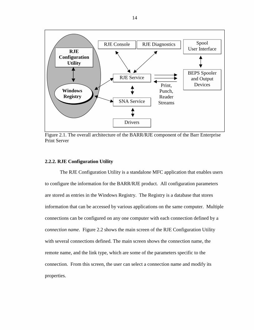
various destinations. Figure 2.1 shows an overview of the BARR/RJE project, which is a
software module of the Barr Enterprise Print Server. BARR/RJE allows the computer on
which it resides to communicate with the mainframe by emulating an IBM 3770, a device
that uses the standard communications protocol. BARR/RJE serves as an input source
that accepts mainframe jobs for further processing and connects to the mainframe in a
variety of low-level communications protocols, including Synchronous Data Link
Control (SDLC), 802.2, and channel connections. The shaded region of the diagram
shows the RJE Configuration Utility and the Windows Registry. Theses are the main
modules used in the case study for this thesis.
14
Figure 2.1. The overall architecture of the BARR/RJE component of the Barr EnterprisePrint Server
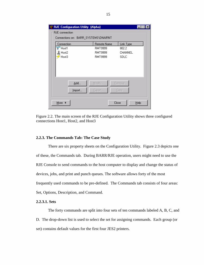
2.2.2. RJE Configuration Utility
The RJE Configuration Utility is a standalone MFC application that enables users
to configure the information for the BARR/RJE product. All configuration parameters
are stored as entries in the Windows Registry. The Registry is a database that stores
information that can be accessed by various applications on the same computer. Multiple
connections can be configured on any one computer with each connection defined by a
connection name. Figure 2.2 shows the main screen of the RJE Configuration Utility
with several connections defined. The main screen shows the connection name, the
remote name, and the link type, which are some of the parameters specific to the
connection. From this screen, the user can select a connection name and modify its
properties.
RJEConfiguration
Utility
SpoolUser Interface
BEPS Spoolerand Output
DevicesRJE Service
SNA Service
Drivers
Windows Registry
Print,Punch,ReaderStreams
RJE DiagnosticsRJE Console
15
Figure 2.2. The main screen of the RJE Configuration Utility shows three configuredconnections Host1, Host2, and Host3
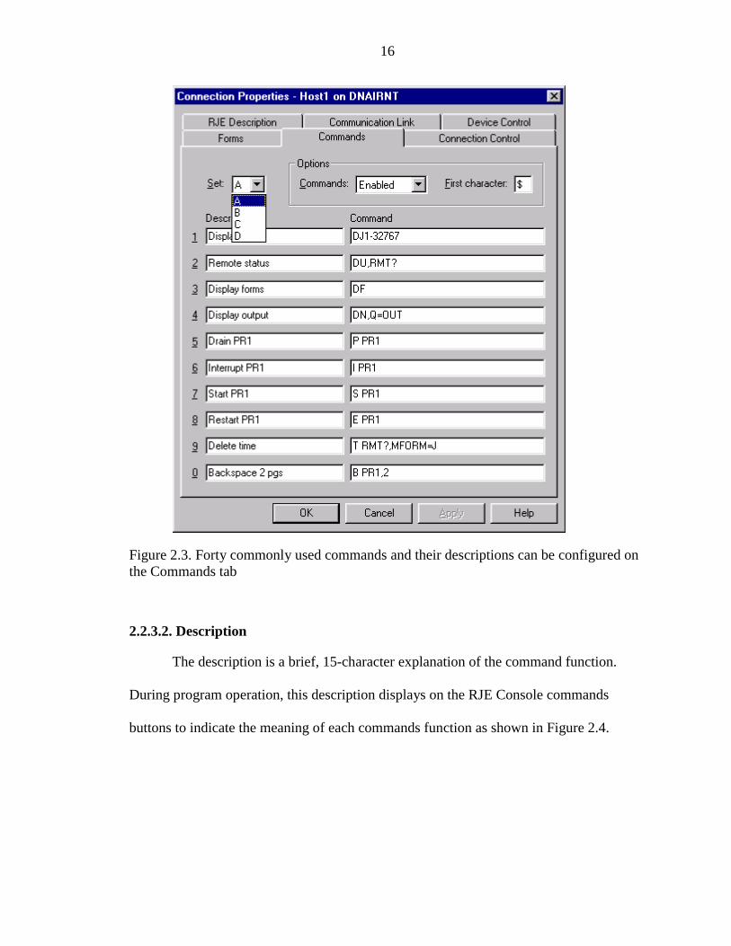
2.2.3. The Commands Tab: The Case Study
There are six property sheets on the Configuration Utility. Figure 2.3 depicts one
of these, the Commands tab. During BARR/RJE operation, users might need to use the
RJE Console to send commands to the host computer to display and change the status of
devices, jobs, and print and punch queues. The software allows forty of the most
frequently used commands to be pre-defined. The Commands tab consists of four areas:
Set, Options, Description, and Command.
2.2.3.1. Sets
The forty commands are split into four sets of ten commands labeled A, B, C, and
D. The drop-down list is used to select the set for assigning commands. Each group (or
set) contains default values for the first four JES2 printers.
16
Figure 2.3. Forty commonly used commands and their descriptions can be configured onthe Commands tab
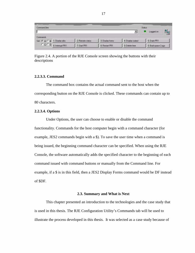
2.2.3.2. Description
The description is a brief, 15-character explanation of the command function.
During program operation, this description displays on the RJE Console commands
buttons to indicate the meaning of each commands function as shown in Figure 2.4.
17
Figure 2.4. A portion of the RJE Console screen showing the buttons with theirdescriptions
2.2.3.3. Command
The command box contains the actual command sent to the host when the
corresponding button on the RJE Console is clicked. These commands can contain up to
80 characters.
2.2.3.4. Options
Under Options, the user can choose to enable or disable the command
functionality. Commands for the host computer begin with a command character (for
example, JES2 commands begin with a $). To save the user time when a command is
being issued, the beginning command character can be specified. When using the RJE
Console, the software automatically adds the specified character to the beginning of each
command issued with command buttons or manually from the Command line. For
example, if a $ is in this field, then a JES2 Display Forms command would be DF instead
of $DF.
2.3. Summary and What is Next
This chapter presented an introduction to the technologies and the case study that
is used in this thesis. The RJE Configuration Utility’s Commands tab will be used to
illustrate the process developed in this thesis. It was selected as a case study because of

18
the unique (and complicated) nature of the data. The information stored in the Registry
will be converted to an XML format, which will allow the user interface to be Web
enabled. The remainder of the RJE Configuration Utility also contains data that might be
interesting to feed through the process at a future time. The following chapter provides a
big-picture view of the conversion process.
19
CHAPTER 3THE BIG PICTURE
The main focus of this thesis is to take an existing graphical user interface (GUI)
code base (software project) and Web-enable it in a manner that will separate the
presentation from the data. Chapter 1 explained a high-level view of the problem and
solution. Chapter 2 presented an overview of the technologies used in this study along
with a background of the case study. This chapter provides a technical explanation of the
conversion engine and a discussion of the setup process.
3.1. Proposed Solution
Figure 1.1 provides a high-level overview of the process from the user’s
perspective. In terms of implementation, the engine works by retrieving information
from storage, displaying it to the user, allowing for modification, and then placing it back
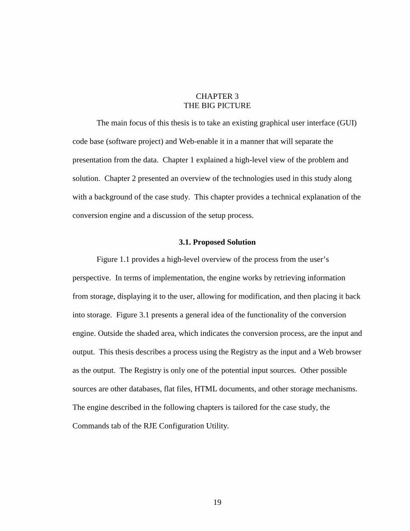
into storage. Figure 3.1 presents a general idea of the functionality of the conversion
engine. Outside the shaded area, which indicates the conversion process, are the input and
output. This thesis describes a process using the Registry as the input and a Web browser
as the output. The Registry is only one of the potential input sources. Other possible
sources are other databases, flat files, HTML documents, and other storage mechanisms.
The engine described in the following chapters is tailored for the case study, the
Commands tab of the RJE Configuration Utility.
20
Figure 3.1. This diagram depicts an overview of the conversion engine
3.2. The Registry
There are many different ways of storing data and information. As technology
has evolved, storage has migrated from flat files to databases. The Windows environment
is created with a global storage mechanism (a database) called the Registry. The
following sections will describe how the Registry is organized and how it can be used.
3.2.1. Using the Windows Registry
The nature of this database allows information to be shared across related
processes. Keys can be nested just like directories, and such keys are referred to as
subkeys. There are six main areas of the Registry for storing information. The only one
used in this thesis is HKEY_LOCAL_MACHINE, which stores system-related
XML� Registry• Launch DLLs• Build
XMLSchemaRegistry
HTMLmenuDLL
Registry �XML• Launch DLLs• Build XML Web
Browser
Submit
CocoonXSLT
User- Interface(Web browser)Registry
Service
ConversionEngine
21
information. The key names for all main areas start with an H to indicate that they are
Win32 handles to keys [Sol00].
Figure 3.2. The Barr RJE key in the Registry stores all RJE configuration information
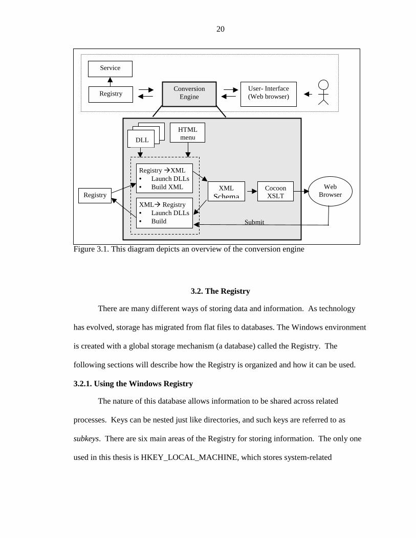
Third-party vendors store information specific to their software under the
HKEY_LOCAL_MACHINE\SOFTWARE key. Figure 3.2 depicts the area of the
Registry that contains the BARR/RJE information. The system provides two tools to
view the information in the Registry: regedit.exe and regedt32.exe. The preferred tool for
this thesis was regedit.exe.
Information can be accessed from the Registry using a standard Windows
application programming interface (API). This API contains functionality for everything
from security protocols to read and write methods. To access a key programmatically
requires a valid Win32 handle. The API for reading and writing a key is similar to that
22
used for reading from and writing to a file. A key can be opened, queried, and closed.
Additional functionality includes enumeration, creation, and deletion. The Registry
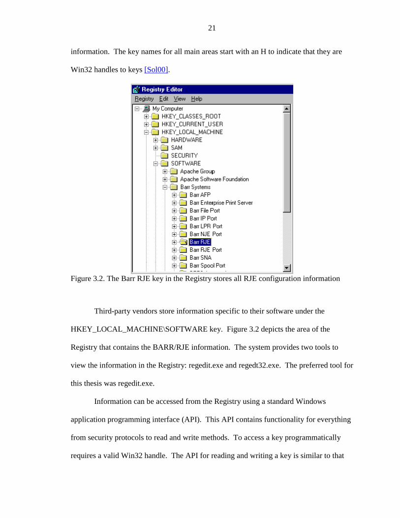
allows information to be stored in multiple formats. Although this flexibility makes it a
very useful tool, it also adds a layer of complexity to the conversion engine. Table 3.1
enumerates some of the commonly used entry formats [Sol00].
Table 3.1. Commonly used Registry formatsValue Meaning
REG_BINARY Binary data (not pre-defined format)REG_DWORD A 32-bit number.
REG_DWORD_LITTLE_ENDIANA 32-bit number in little-endian format. In little-endian format, the lower byte is specified first.This is equivalent to REG_DWORD.
REG_DWORD_BIG_ENDIAN A 32-bit number in big-endian format. In big-endian format, the higher byte is specified first.
REG_EXPAND_SZVariable-length Unicode null-terminated stringthat contains unexpanded references toenvironment variables.
REG_LINK A Unicode symbolic link. Used internally;applications should not use this type.
REG_MULTI_SZ An array of Unicode null-terminated strings.REG_NONE No defined value type.REG_RESOURCE_LIST A hardware resource list.
REG_SZ A null-terminated string. Either Unicode orANSI depending on function.
3.2.2. Format of the Barr Registry
The Barr RJE key contains all the information for configuration of an RJE
connection. The configuration data is stored in a subkey, Connections, which contains
subkeys labeled by the corresponding connection name. The keys under the connection
name are organized by the information associated with each property (tab) page of the
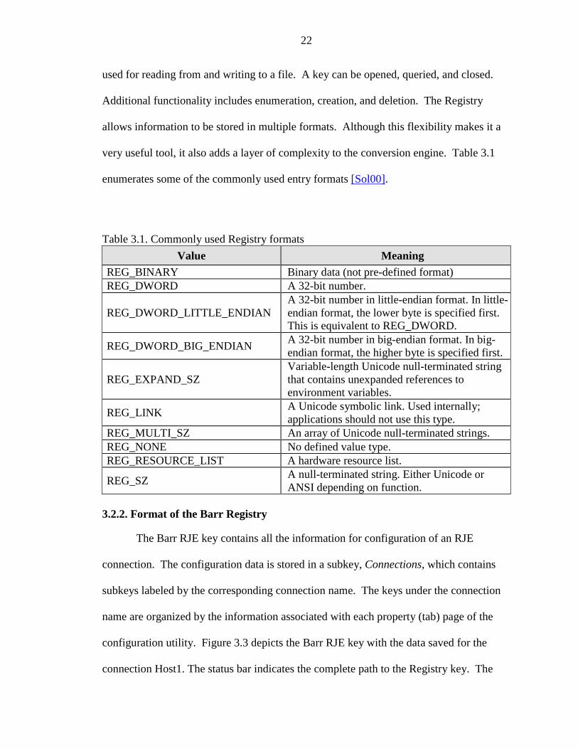
configuration utility. Figure 3.3 depicts the Barr RJE key with the data saved for the
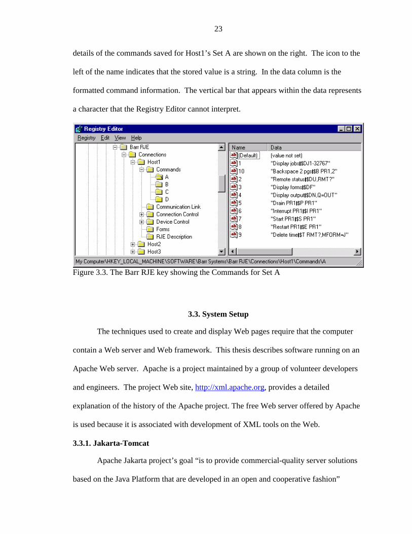
connection Host1. The status bar indicates the complete path to the Registry key. The
23
details of the commands saved for Host1’s Set A are shown on the right. The icon to the
left of the name indicates that the stored value is a string. In the data column is the
formatted command information. The vertical bar that appears within the data represents
a character that the Registry Editor cannot interpret.
Figure 3.3. The Barr RJE key showing the Commands for Set A
3.3. System Setup
The techniques used to create and display Web pages require that the computer
contain a Web server and Web framework. This thesis describes software running on an
Apache Web server. Apache is a project maintained by a group of volunteer developers
and engineers. The project Web site, http://xml.apache.org, provides a detailed
explanation of the history of the Apache project. The free Web server offered by Apache
is used because it is associated with development of XML tools on the Web.
3.3.1. Jakarta-Tomcat
Apache Jakarta project’s goal “is to provide commercial-quality server solutions
based on the Java Platform that are developed in an open and cooperative fashion”
24
[http://jakarta.apache.org/index.html]. There are many subprojects of Jakarta, one of
which is Tomcat. “Tomcat is the Reference Implementation for the Java Servlet 2.2 and
JavaServer Pages 1.1 Technologies. Tomcat is the official reference implementation for
these complementary technologies” [http://jakarta.apache.org/tomcat/index.html].
Tomcat requires version 1.3 of the Java Development Kit (JDK) on the system.
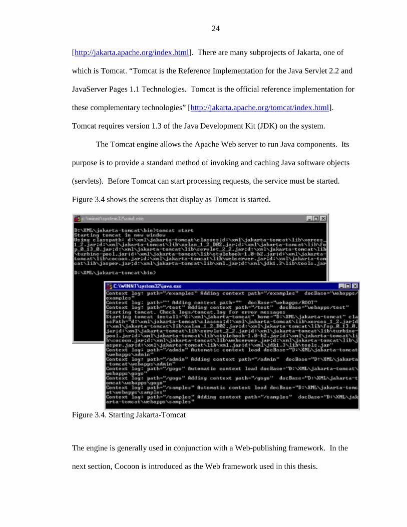
The Tomcat engine allows the Apache Web server to run Java components. Its
purpose is to provide a standard method of invoking and caching Java software objects
(servlets). Before Tomcat can start processing requests, the service must be started.
Figure 3.4 shows the screens that display as Tomcat is started.
Figure 3.4. Starting Jakarta-Tomcat
The engine is generally used in conjunction with a Web-publishing framework. In the
next section, Cocoon is introduced as the Web framework used in this thesis.
25
3.3.2. Cocoon: A Web-publishing framework
A Web server responds to a Uniform Resource Locator (URL) request to display
a file on the Web browser. Similarly, a Web-publishing framework manipulates the data
found in a specified file into a presentation format such as HTML. There are several data
manipulation methods, one of which is a transformation using XSLT [McL00]. With the
rise in the XML/XSL technology, several different Web-publishing frameworks were
introduced. The framework used in this thesis is Apache Cocoon, “a 100% pure Java
publishing framework that relies on new W3C technologies (such as DOM, XML, and
XSL) to provide Web content” [http://xml.apache.org/cocoon/index.html]. To process
requests, Cocoon must be configured to work with a servlet engine.
In this thesis, Cocoon is configured to use the Tomcat engine to determine which
requests Cocoon should handle. A test for determining if the installation is successful is
trying to access http://<hostname>:<port>/Cocoon.xml and in the case of this thesis
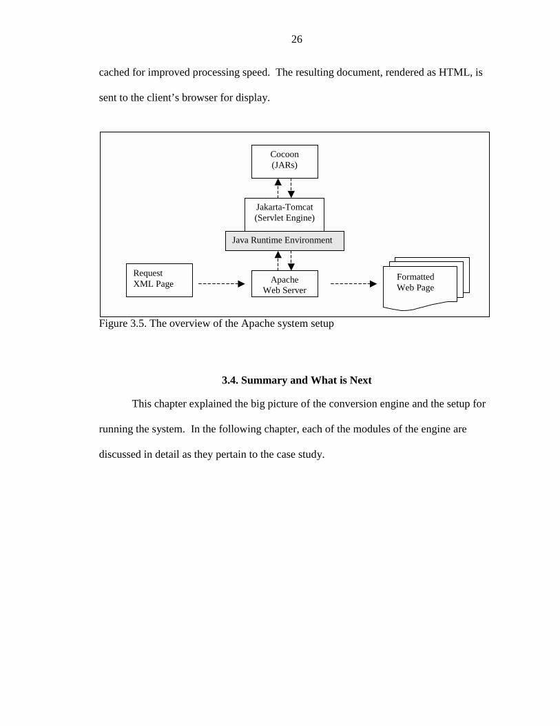
http://dnairnt.barrsystems.com:8080/Cocoon.xml. Figure 3.5 shows the relationship
among the various setup components.
The purpose of installing Cocoon on the machine is to provide a way to perform
XML-based publishing using Java. The Apache Web server that maps the document to a
corresponding Cocoon.jar file handles an XML request. The JAR file contains the
parameters that will allow Cocoon to communicate with the Tomcat engine. Jakarta-
Tomcat, which runs on a Sun Java Runtime Environment, routes the request to the
corresponding Java servlet. Cocoon processes the request after loading the necessary
support libraries and configuration files. The information store in an XML document is
parsed, and the proper transformation is invoked based on the specified processing
instruction found in the XML file. All Java servlets are managed through Tomcat and
26
cached for improved processing speed. The resulting document, rendered as HTML, is
sent to the client’s browser for display.
Figure 3.5. The overview of the Apache system setup
3.4. Summary and What is Next
This chapter explained the big picture of the conversion engine and the setup for
running the system. In the following chapter, each of the modules of the engine are
discussed in detail as they pertain to the case study.
ApacheWeb Server
Jakarta-Tomcat(Servlet Engine)
Java Runtime Environment
Cocoon(JARs)
RequestXML Page
FormattedWeb Page
27
CHAPTER 4CONVERSION ENGINE
Figure 3.1 presented an overview of the conversion engine. This chapter contains
a detailed analysis of each component of the design as they apply specifically to the case
study. The first section explains the technique used to extract the data from the Registry
and format it into an XML document. The second section discusses the processing of the
XML to format it for a Web browser. The third section describes how the data is
submitted from the Web browser to the Registry.
4.1. Registry to XML
The first part of the conversion process is a program module that builds an XML
data file containing the information stored in a specific key of the Registry. This module,
written in Microsoft Visual C++, generates a standalone console application
(regxml.exe). To show proof-of-concept, the regxml process is launched with “Barr
RJE” hard-coded as the command-line parameter.
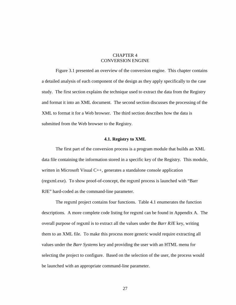
The regxml project contains four functions. Table 4.1 enumerates the function
descriptions. A more complete code listing for regxml can be found in Appendix A. The
overall purpose of regxml is to extract all the values under the Barr RJE key, writing
them to an XML file. To make this process more generic would require extracting all
values under the Barr Systems key and providing the user with an HTML menu for
selecting the project to configure. Based on the selection of the user, the process would
be launched with an appropriate command-line parameter.
28
Table 4.1. Description of all functions in the regxml projectFunction Declaration Descriptionint _tmain(int argc,TCHAR* argv[],TCHAR* envp[])
This function is the entry point into the application. Itreads the command-line parameters and builds an XMLfile for the specified Registry key.
voidGenerateXMLfile(HKEY hKey,CString csProject)
Generates the XML file for a specific Registry key (hKey)based on the project name (csProject). The file is stored inthe Jakarta-Tomcat hierarchy so the Web server can accessit.
void EmumerateKeys(HKEY hKey,CString csRegPath,FILE* fptr)
Recursively enumerates all the keys and subkeys and callsthe EnumerateValues method with the corresponding keyand file pointer.
voidEmumerateValues(HKEY hKey,CString csRegPath,FILE* fptr)
Enumerates the values for all the data in the keys. Thedata are formatted and written to the file.
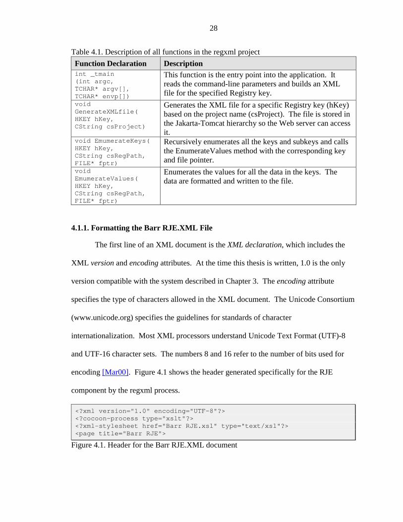
4.1.1. Formatting the Barr RJE.XML File
The first line of an XML document is the XML declaration, which includes the
XML version and encoding attributes. At the time this thesis is written, 1.0 is the only
version compatible with the system described in Chapter 3. The encoding attribute
specifies the type of characters allowed in the XML document. The Unicode Consortium
(www.unicode.org) specifies the guidelines for standards of character
internationalization. Most XML processors understand Unicode Text Format (UTF)-8
and UTF-16 character sets. The numbers 8 and 16 refer to the number of bits used for
encoding [Mar00]. Figure 4.1 shows the header generated specifically for the RJE
component by the regxml process.
<?xml version="1.0" encoding="UTF-8"?><?cocoon-process type="xslt"?><?xml-stylesheet href="Barr RJE.xsl" type="text/xsl"?><page title="Barr RJE">
Figure 4.1. Header for the Barr RJE.XML document
29
The XML specification permits processing instructions, which are directions to
the various processing programs. In this case, the instruction informs Cocoon that the file
to associate with the XML document is an XSLT (stylesheet) file. The corresponding tag
in Figure 4.1 is <?cocoon-process>.
The <?xml-stylesheet> tag specifies the name of the document’s corresponding
XSL stylesheet. When this document is loaded into a Web browser, it is displayed
according to the formatting provided by the specifications of the style sheet. One simple
test to determine if a document is well formed is to load it into a Web browser without a
reference to a style sheet. The browser flags any parse errors and indicates the faulting
character, if applicable. Every well formed document has a root node, the node
containing all the other nodes. The root node specified in Figure 4.1 is page with the
attribute of title. This suggests that the entire document content is specified within
<page> </page> tags [Mar00].
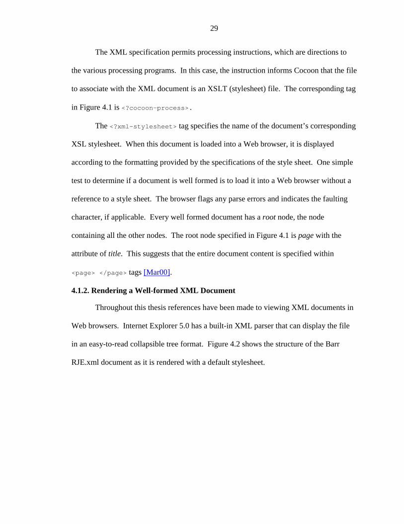
4.1.2. Rendering a Well-formed XML Document
Throughout this thesis references have been made to viewing XML documents in
Web browsers. Internet Explorer 5.0 has a built-in XML parser that can display the file
in an easy-to-read collapsible tree format. Figure 4.2 shows the structure of the Barr
RJE.xml document as it is rendered with a default stylesheet.
30
Figure 4.2. The collapsible-tree format of an XML document in Internet Explorer
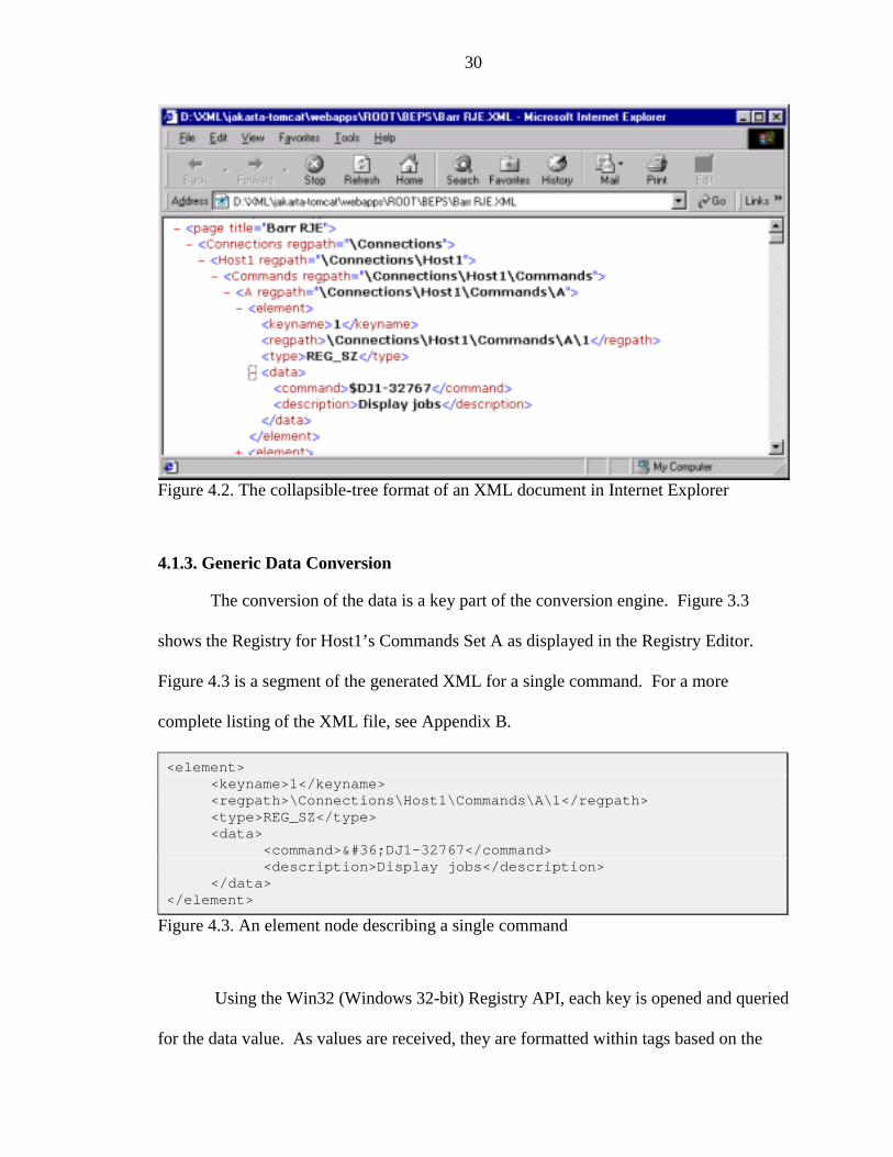
4.1.3. Generic Data Conversion
The conversion of the data is a key part of the conversion engine. Figure 3.3
shows the Registry for Host1’s Commands Set A as displayed in the Registry Editor.
Figure 4.3 is a segment of the generated XML for a single command. For a more
complete listing of the XML file, see Appendix B.
<element><keyname>1</keyname><regpath>\Connections\Host1\Commands\A\1</regpath><type>REG_SZ</type><data>
<command>$DJ1-32767</command><description>Display jobs</description>
</data></element>
Figure 4.3. An element node describing a single command
Using the Win32 (Windows 32-bit) Registry API, each key is opened and queried
for the data value. As values are received, they are formatted within tags based on the
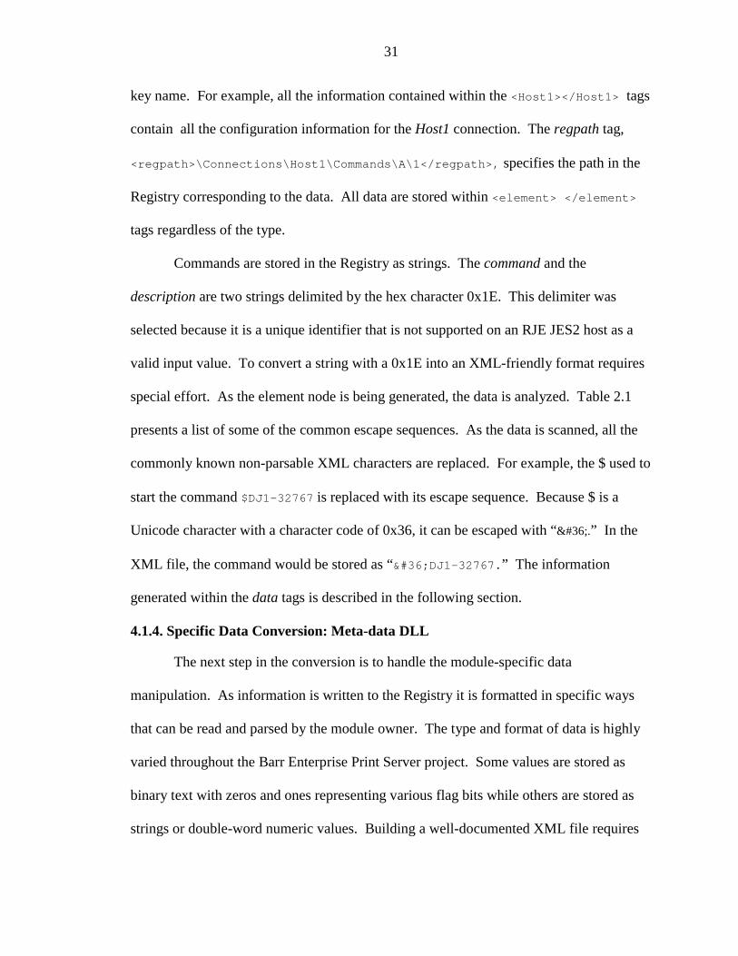
31
key name. For example, all the information contained within the <Host1></Host1> tags
contain all the configuration information for the Host1 connection. The regpath tag,
<regpath>\Connections\Host1\Commands\A\1</regpath>, specifies the path in the
Registry corresponding to the data. All data are stored within <element> </element>
tags regardless of the type.
Commands are stored in the Registry as strings. The command and the
description are two strings delimited by the hex character 0x1E. This delimiter was
selected because it is a unique identifier that is not supported on an RJE JES2 host as a
valid input value. To convert a string with a 0x1E into an XML-friendly format requires
special effort. As the element node is being generated, the data is analyzed. Table 2.1
presents a list of some of the common escape sequences. As the data is scanned, all the
commonly known non-parsable XML characters are replaced. For example, the $ used to
start the command $DJ1-32767 is replaced with its escape sequence. Because $ is a
Unicode character with a character code of 0x36, it can be escaped with “$.” In the
XML file, the command would be stored as “$DJ1-32767.” The information
generated within the data tags is described in the following section.
4.1.4. Specific Data Conversion: Meta-data DLL
The next step in the conversion is to handle the module-specific data
manipulation. As information is written to the Registry it is formatted in specific ways
that can be read and parsed by the module owner. The type and format of data is highly
varied throughout the Barr Enterprise Print Server project. Some values are stored as
binary text with zeros and ones representing various flag bits while others are stored as
strings or double-word numeric values. Building a well-documented XML file requires
32
that the data is understandable outside of the creation module. Therefore, the data should
be extracted into a more readable format. Given the purpose and understanding the need
to minimize code change resulted in the creation and use of the meta-data dynamic-link
libraries (DLL).
DLLs are runtime modular entities that can be tested independently. When
loaded by an application, they become part of its process space. A definition file (.def)
contains a table of exported functions. Within the code, the functions are explicitly
declared in the “__declspec(dllexport) <return type> <function name>” format
to indicate that they provide an entry-point into the library [Kru97].
In a complete system, there would be a corresponding configuration DLL for each
project or subproject. This file is a library collection of methods containing detailed
knowledge of the data representation. The purpose of the meta-data DLL is to provide
specific knowledge on the exact format of the data and use this to extract from and write
to the corresponding XML data. BarrRje.dll contains the processing information for RJE
configuration data. Table 4.2 enumerates the function declaration that pertains to the
regxml project.
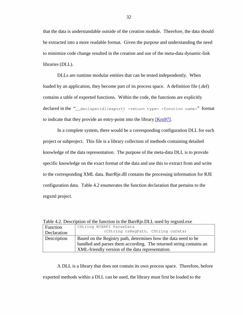
Table 4.2. Description of the function in the BarrRje.DLL used by regxml.exeFunctionDeclaration
CString WINAPI ParseData(CString csRegPath, CString csData)
Description Based on the Registry path, determines how the data need to behandled and parses them according. The returned string contains anXML-friendly version of the data representation.
A DLL is a library that does not contain its own process space. Therefore, before
exported methods within a DLL can be used, the library must first be loaded to the
33
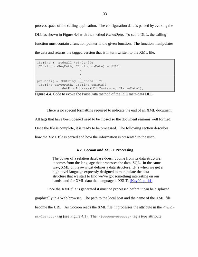
process space of the calling application. The configuration data is parsed by evoking the
DLL as shown in Figure 4.4 with the method ParseData. To call a DLL, the calling
function must contain a function pointer to the given function. The function manipulates
the data and returns the tagged version that is in turn written to the XML file.
CString (__stdcall *pFnConfig)(CString csRegPath, CString csData) = NULL;
.
.
.pFnConfig = (CString (__stdcall *)(CString csRegPath, CString csData))
::GetProcAddress(hDllInstance, "ParseData");
Figure 4.4. Code to evoke the ParseData method of the RJE meta-data DLL
There is no special formatting required to indicate the end of an XML document.
All tags that have been opened need to be closed so the document remains well formed.
Once the file is complete, it is ready to be processed. The following section describes
how the XML file is parsed and how the information is presented to the user.
4.2. Cocoon and XSLT Processing
The power of a relation database doesn’t come from its data structure;it comes from the language that processes the data, SQL. In the sameway, XML on its own just defines a data structure…It’s when we get ahigh-level language expressly designed to manipulate the datastructure that we start to find we’ve got something interesting on ourhands: and for XML data that language is XSLT. [Kay00, p. 14]
Once the XML file is generated it must be processed before it can be displayed
graphically in a Web browser. The path to the local host and the name of the XML file
become the URL. As Cocoon reads the XML file, it processes the attribute in the <?xml-
stylesheet> tag (see Figure 4.1). The <?cocoon-process> tag’s type attribute
34
indicates the processing is XSLT. The corresponding XSL file must be located in the
same path as the XML file.
4.2.1. Template Matching
Chapter 2 introduced style sheets and made the analogy that XSL is to an XML
file like SQL is to a database. Style sheets can be built to contain many template rules
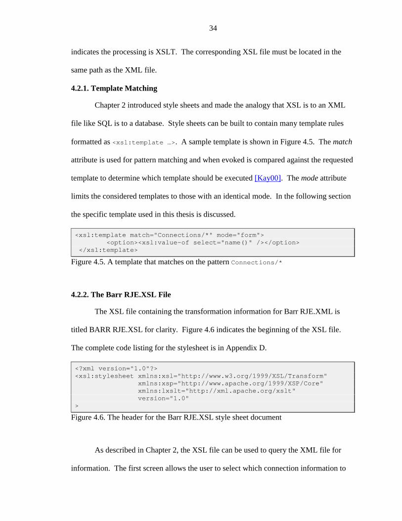
formatted as <xsl:template …>. A sample template is shown in Figure 4.5. The match
attribute is used for pattern matching and when evoked is compared against the requested
template to determine which template should be executed [Kay00]. The mode attribute
limits the considered templates to those with an identical mode. In the following section
the specific template used in this thesis is discussed.
<xsl:template match="Connections/*" mode="form"><option><xsl:value-of select="name()" /></option>
</xsl:template>
Figure 4.5. A template that matches on the pattern Connections/*
4.2.2. The Barr RJE.XSL File
The XSL file containing the transformation information for Barr RJE.XML is
titled BARR RJE.XSL for clarity. Figure 4.6 indicates the beginning of the XSL file.
The complete code listing for the stylesheet is in Appendix D.
<?xml version="1.0"?><xsl:stylesheet xmlns:xsl="http://www.w3.org/1999/XSL/Transform"
xmlns:xsp="http://www.apache.org/1999/XSP/Core"xmlns:lxslt="http://xml.apache.org/xslt"version="1.0"
>
Figure 4.6. The header for the Barr RJE.XSL style sheet document
As described in Chapter 2, the XSL file can be used to query the XML file for
information. The first screen allows the user to select which connection information to
35
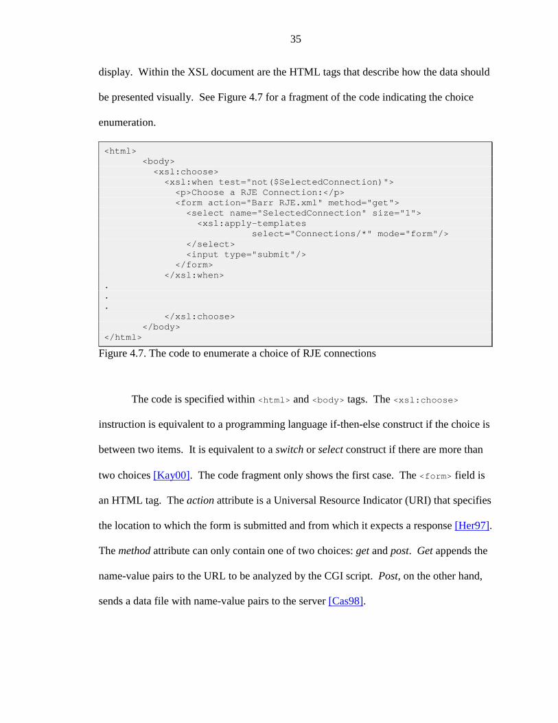
display. Within the XSL document are the HTML tags that describe how the data should
be presented visually. See Figure 4.7 for a fragment of the code indicating the choice
enumeration.
<html><body>
<xsl:choose><xsl:when test="not($SelectedConnection)">
<p>Choose a RJE Connection:</p><form action="Barr RJE.xml" method="get">
<select name="SelectedConnection" size="1"><xsl:apply-templates
select="Connections/*" mode="form"/></select><input type="submit"/>
</form></xsl:when>
.
.
.</xsl:choose>
</body></html>
Figure 4.7. The code to enumerate a choice of RJE connections
The code is specified within <html> and <body> tags. The <xsl:choose>
instruction is equivalent to a programming language if-then-else construct if the choice is
between two items. It is equivalent to a switch or select construct if there are more than
two choices [Kay00]. The code fragment only shows the first case. The <form> field is
an HTML tag. The action attribute is a Universal Resource Indicator (URI) that specifies
the location to which the form is submitted and from which it expects a response [Her97].
The method attribute can only contain one of two choices: get and post. Get appends the
name-value pairs to the URL to be analyzed by the CGI script. Post, on the other hand,
sends a data file with name-value pairs to the server [Cas98].
36
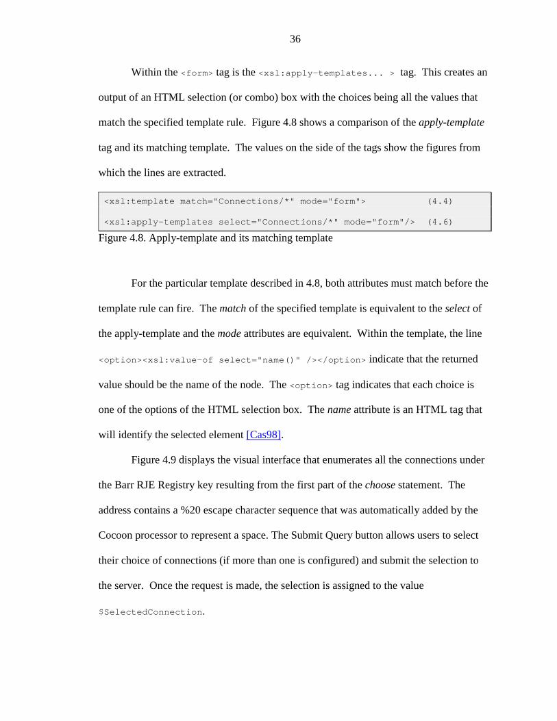
Within the <form> tag is the <xsl:apply-templates... > tag. This creates an
output of an HTML selection (or combo) box with the choices being all the values that
match the specified template rule. Figure 4.8 shows a comparison of the apply-template
tag and its matching template. The values on the side of the tags show the figures from
which the lines are extracted.
<xsl:template match="Connections/*" mode="form"> (4.4)
<xsl:apply-templates select="Connections/*" mode="form"/> (4.6)
Figure 4.8. Apply-template and its matching template
For the particular template described in 4.8, both attributes must match before the
template rule can fire. The match of the specified template is equivalent to the select of
the apply-template and the mode attributes are equivalent. Within the template, the line
<option><xsl:value-of select="name()" /></option> indicate that the returned
value should be the name of the node. The <option> tag indicates that each choice is
one of the options of the HTML selection box. The name attribute is an HTML tag that
will identify the selected element [Cas98].
Figure 4.9 displays the visual interface that enumerates all the connections under
the Barr RJE Registry key resulting from the first part of the choose statement. The
address contains a %20 escape character sequence that was automatically added by the
Cocoon processor to represent a space. The Submit Query button allows users to select
their choice of connections (if more than one is configured) and submit the selection to
the server. Once the request is made, the selection is assigned to the value
$SelectedConnection.
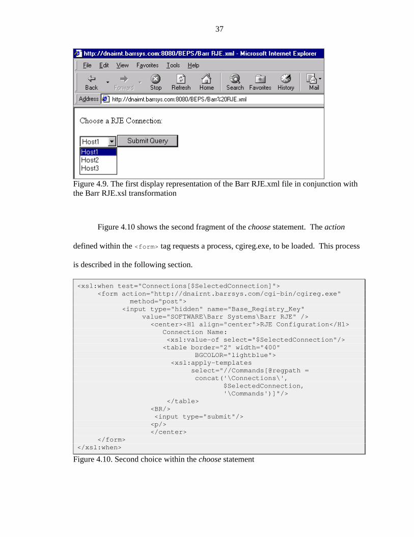
37
Figure 4.9. The first display representation of the Barr RJE.xml file in conjunction withthe Barr RJE.xsl transformation
Figure 4.10 shows the second fragment of the choose statement. The action
defined within the <form> tag requests a process, cgireg.exe, to be loaded. This process
is described in the following section.
<xsl:when test="Connections[$SelectedConnection]"><form action="http://dnairnt.barrsys.com/cgi-bin/cgireg.exe"
method="post"><input type="hidden" name="Base_Registry_Key"
value="SOFTWARE\Barr Systems\Barr RJE" /><center><H1 align="center">RJE Configuration</H1>
Connection Name:<xsl:value-of select="$SelectedConnection"/><table border="2" width="400"
BGCOLOR="lightblue"><xsl:apply-templates
select="//Commands[@regpath =concat('\Connections\',
$SelectedConnection,'\Commands')]"/>
</table><BR/><input type="submit"/><p/></center>
</form></xsl:when>
Figure 4.10. Second choice within the choose statement
38
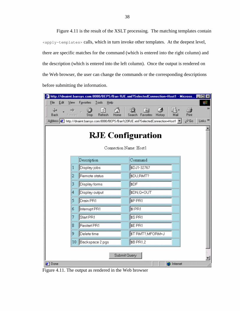
Figure 4.11 is the result of the XSLT processing. The matching templates contain
<apply-templates> calls, which in turn invoke other templates. At the deepest level,
there are specific matches for the command (which is entered into the right column) and
the description (which is entered into the left column). Once the output is rendered on
the Web browser, the user can change the commands or the corresponding descriptions
before submitting the information.
Figure 4.11. The output as rendered in the Web browser
39
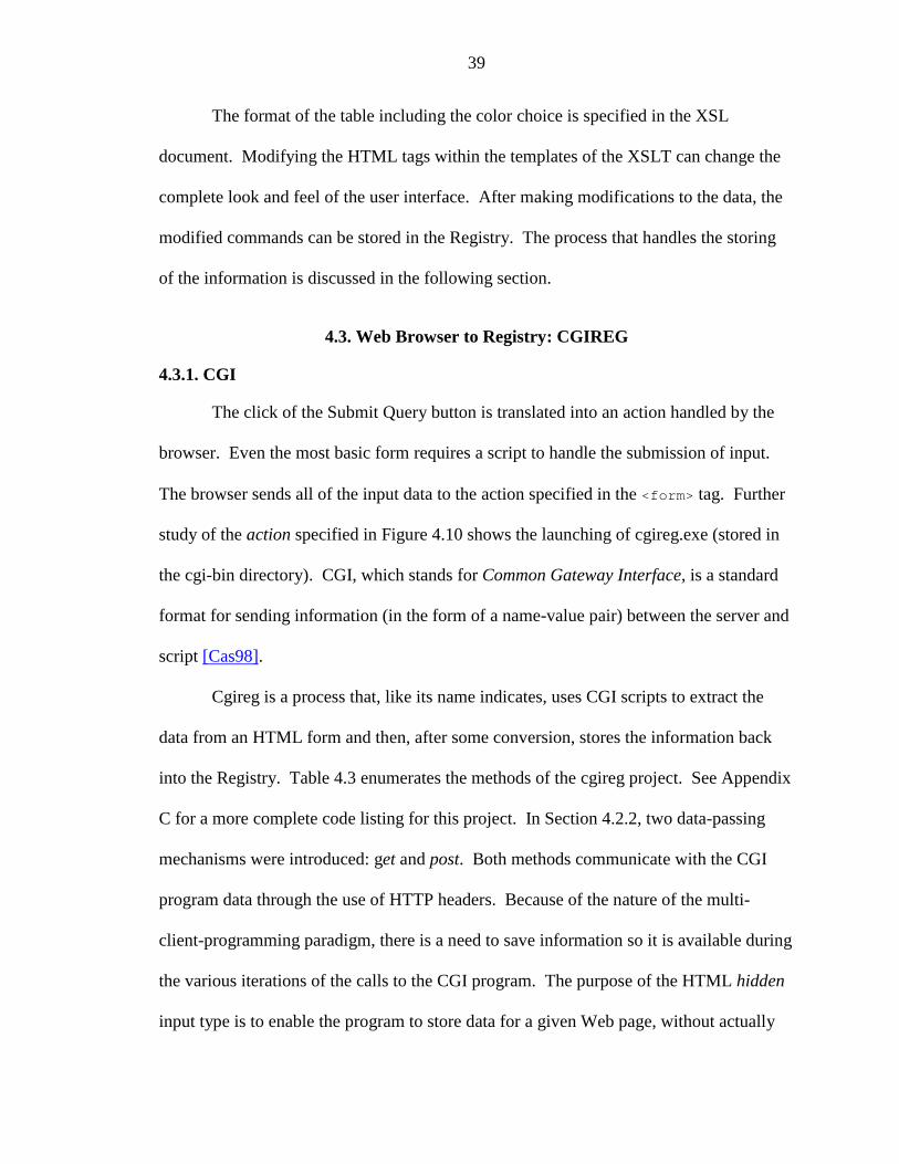
The format of the table including the color choice is specified in the XSL
document. Modifying the HTML tags within the templates of the XSLT can change the
complete look and feel of the user interface. After making modifications to the data, the
modified commands can be stored in the Registry. The process that handles the storing
of the information is discussed in the following section.
4.3. Web Browser to Registry: CGIREG
4.3.1. CGI
The click of the Submit Query button is translated into an action handled by the
browser. Even the most basic form requires a script to handle the submission of input.
The browser sends all of the input data to the action specified in the <form> tag. Further
study of the action specified in Figure 4.10 shows the launching of cgireg.exe (stored in
the cgi-bin directory). CGI, which stands for Common Gateway Interface, is a standard
format for sending information (in the form of a name-value pair) between the server and
script [Cas98].
Cgireg is a process that, like its name indicates, uses CGI scripts to extract the
data from an HTML form and then, after some conversion, stores the information back
into the Registry. Table 4.3 enumerates the methods of the cgireg project. See Appendix
C for a more complete code listing for this project. In Section 4.2.2, two data-passing
mechanisms were introduced: get and post. Both methods communicate with the CGI
program data through the use of HTTP headers. Because of the nature of the multi-
client-programming paradigm, there is a need to save information so it is available during
the various iterations of the calls to the CGI program. The purpose of the HTML hidden
input type is to enable the program to store data for a given Web page, without actually
40
requiring that it be displayed. The problem with this information is that it is only hidden
from the perspective of the display. If users choose to view the source of the HTML file,
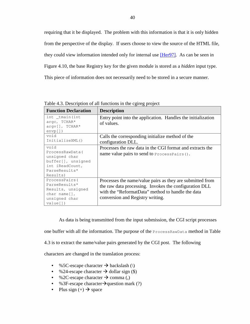
they could view information intended only for internal use [Her97]. As can be seen in
Figure 4.10, the base Registry key for the given module is stored as a hidden input type.
This piece of information does not necessarily need to be stored in a secure manner.
Table 4.3. Description of all functions in the cgireg projectFunction Declaration Descriptionint _tmain(intargc, TCHAR*argv[], TCHAR*envp[])
Entry point into the application. Handles the initializationof values.
voidInitializeXML()
Calls the corresponding initialize method of theconfiguration DLL.
voidProcessRawData(unsigned charbuffer[], unsignedint iReadCount,ParseResults*Results)
Processes the raw data in the CGI format and extracts thename value pairs to send to ProcessPairs().
ProcessPairs(ParseResults*Results, unsignedchar name[],unsigned charvalue[])
Processes the name/value pairs as they are submitted fromthe raw data processing. Invokes the configuration DLLwith the “ReformatData” method to handle the dataconversion and Registry writing.
As data is being transmitted from the input submission, the CGI script processes
one buffer with all the information. The purpose of the ProcessRawData method in Table
4.3 is to extract the name/value pairs generated by the CGI post. The following
characters are changed in the translation process:
• %5C-escape character � backslash (\)• %24-escape character � dollar sign ($)• %2C-escape character � comma (,)• %3F-escape character�question mark (?)• Plus sign (+) � space
41
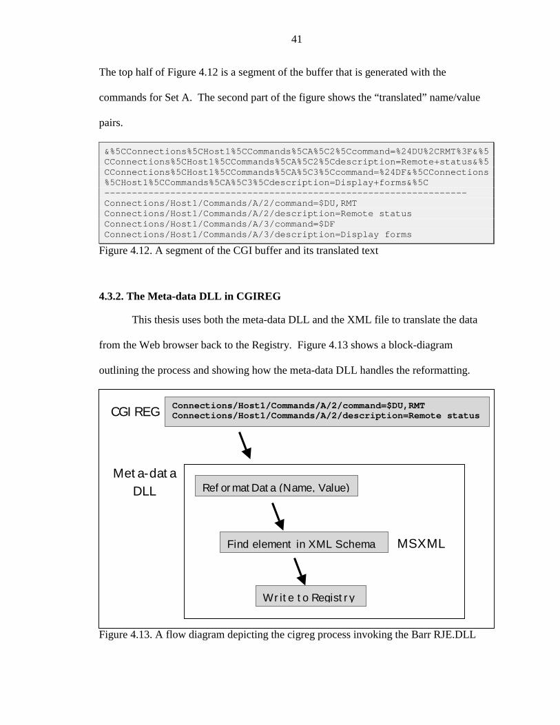
The top half of Figure 4.12 is a segment of the buffer that is generated with the
commands for Set A. The second part of the figure shows the “translated” name/value
pairs.
&%5CConnections%5CHost1%5CCommands%5CA%5C2%5Ccommand=%24DU%2CRMT%3F&%5CConnections%5CHost1%5CCommands%5CA%5C2%5Cdescription=Remote+status&%5CConnections%5CHost1%5CCommands%5CA%5C3%5Ccommand=%24DF&%5CConnections%5CHost1%5CCommands%5CA%5C3%5Cdescription=Display+forms&%5C------------------------------------------------------------------Connections/Host1/Commands/A/2/command=$DU,RMTConnections/Host1/Commands/A/2/description=Remote statusConnections/Host1/Commands/A/3/command=$DFConnections/Host1/Commands/A/3/description=Display forms
Figure 4.12. A segment of the CGI buffer and its translated text
4.3.2. The Meta-data DLL in CGIREG
This thesis uses both the meta-data DLL and the XML file to translate the data
from the Web browser back to the Registry. Figure 4.13 shows a block-diagram
outlining the process and showing how the meta-data DLL handles the reformatting.
Figure 4.13. A flow diagram depicting the cigreg process invoking the Barr RJE.DLL
Connections/Host1/Commands/A/2/command=$DU,RMTConnections/Host1/Commands/A/2/description=Remote status
ReformatData (Name, Value)Meta-data
DLL
CGIREG
Find element in XML Schema MSXML
Write to Registry
42
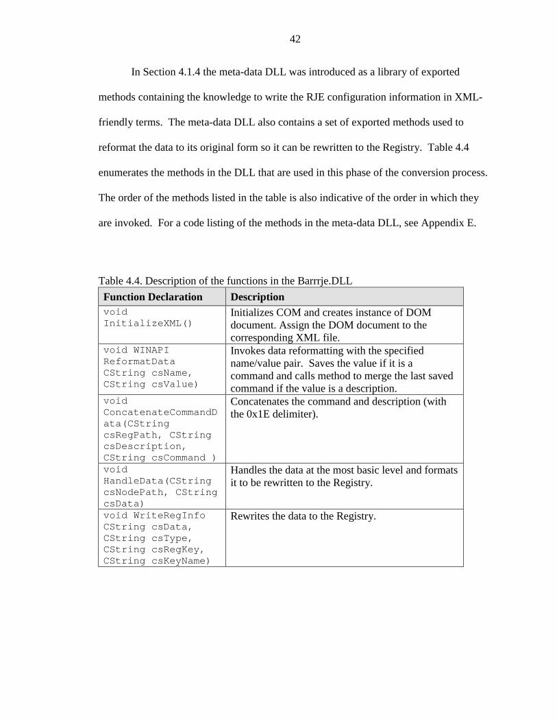
In Section 4.1.4 the meta-data DLL was introduced as a library of exported
methods containing the knowledge to write the RJE configuration information in XML-
friendly terms. The meta-data DLL also contains a set of exported methods used to
reformat the data to its original form so it can be rewritten to the Registry. Table 4.4
enumerates the methods in the DLL that are used in this phase of the conversion process.
The order of the methods listed in the table is also indicative of the order in which they
are invoked. For a code listing of the methods in the meta-data DLL, see Appendix E.
Table 4.4. Description of the functions in the Barrrje.DLLFunction Declaration DescriptionvoidInitializeXML()
Initializes COM and creates instance of DOMdocument. Assign the DOM document to thecorresponding XML file.
void WINAPIReformatDataCString csName,CString csValue)
Invokes data reformatting with the specifiedname/value pair. Saves the value if it is acommand and calls method to merge the last savedcommand if the value is a description.
voidConcatenateCommandData(CStringcsRegPath, CStringcsDescription,CString csCommand )
Concatenates the command and description (withthe 0x1E delimiter).
voidHandleData(CStringcsNodePath, CStringcsData)
Handles the data at the most basic level and formatsit to be rewritten to the Registry.
void WriteRegInfoCString csData,CString csType,CString csRegKey,CString csKeyName)
Rewrites the data to the Registry.
43
The methods described in Table 4.4 contain references to COM and DOM. The
following section describes the details of the API used to parse the XML document as it
pertains to the cgireg project module.
4.3.3. Document Object Module using MSXML
In Chapter 2, DOM, or Document Object Model, and SAX, or Simple API for
XML, were introduced as APIs for extracting information from a raw XML document
using an XML parser. In this section we discuss the way DOM is used in this thesis and
the reasons why it was implemented instead of SAX.
In developing a set of interfaces for parsing XML documents, Microsoft
introduced MSXML. MSXML is based on the COM technology. COM, or Component
Object Model, is a software architecture that uses components as the basis of creating
applications and systems. By creating a set of interfaces that can be used by various
program modules, the COM architecture allows different software vendors to use the
same components without having to redevelop them.
MSXML contains a DOM XML parser that is as an extension to the W3C DOM
Recommendation as well as a subset of the W3C XSTL processor [Kay00]. As with all
developing technologies, the version changes are a natural evolution of the software
process. MSXML version 2.5 is used in this thesis. The components described within
MSXML can be used in a variety of programming languages including Visual Basic,
Java, and Visual C++. Because development for the thesis is done in Visual C++ the
following discussion of objects and their uses are specific to the C++ methods.
There are two key objects defined for the parser: a document pointer
(IXMLDOMDocumentPtr m_plDomDocument) and an element pointer
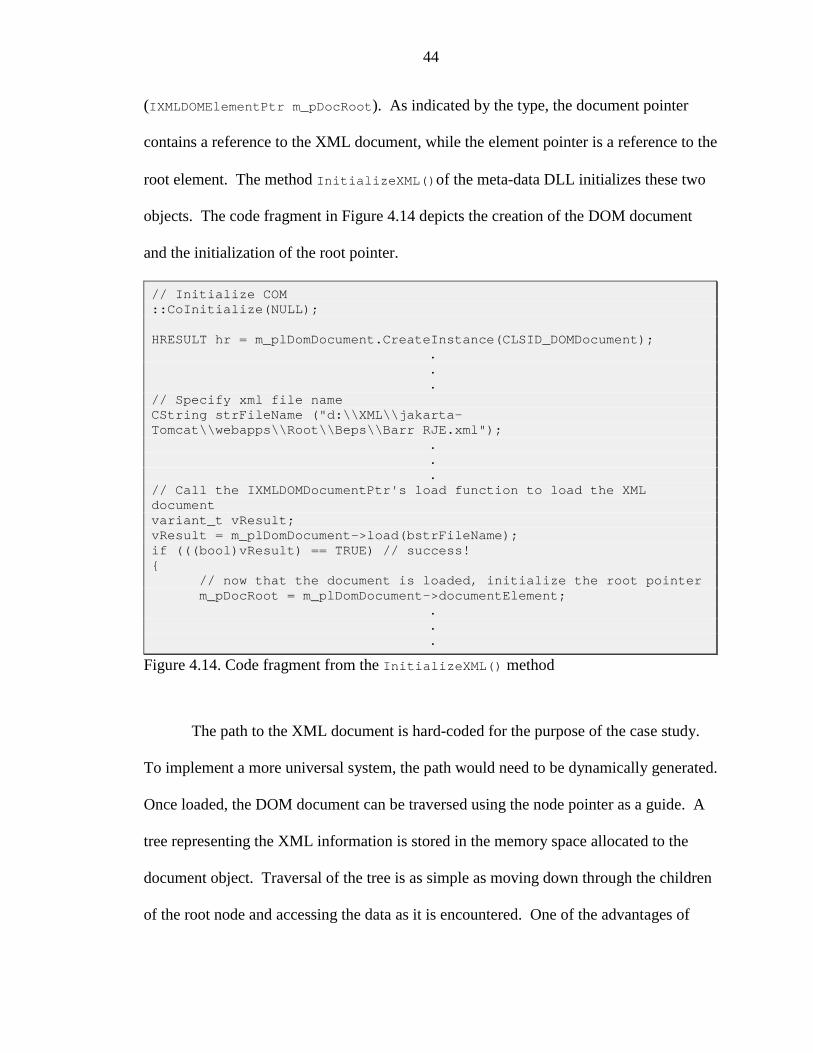
44
(IXMLDOMElementPtr m_pDocRoot). As indicated by the type, the document pointer
contains a reference to the XML document, while the element pointer is a reference to the
root element. The method InitializeXML()of the meta-data DLL initializes these two
objects. The code fragment in Figure 4.14 depicts the creation of the DOM document
and the initialization of the root pointer.
// Initialize COM::CoInitialize(NULL);
HRESULT hr = m_plDomDocument.CreateInstance(CLSID_DOMDocument);...
// Specify xml file nameCString strFileName ("d:\\XML\\jakarta-Tomcat\\webapps\\Root\\Beps\\Barr RJE.xml");
.
.
.// Call the IXMLDOMDocumentPtr's load function to load the XMLdocumentvariant_t vResult;vResult = m_plDomDocument->load(bstrFileName);if (((bool)vResult) == TRUE) // success!{
// now that the document is loaded, initialize the root pointerm_pDocRoot = m_plDomDocument->documentElement;
.
.
.
Figure 4.14. Code fragment from the InitializeXML() method
The path to the XML document is hard-coded for the purpose of the case study.
To implement a more universal system, the path would need to be dynamically generated.
Once loaded, the DOM document can be traversed using the node pointer as a guide. A
tree representing the XML information is stored in the memory space allocated to the
document object. Traversal of the tree is as simple as moving down through the children
of the root node and accessing the data as it is encountered. One of the advantages of
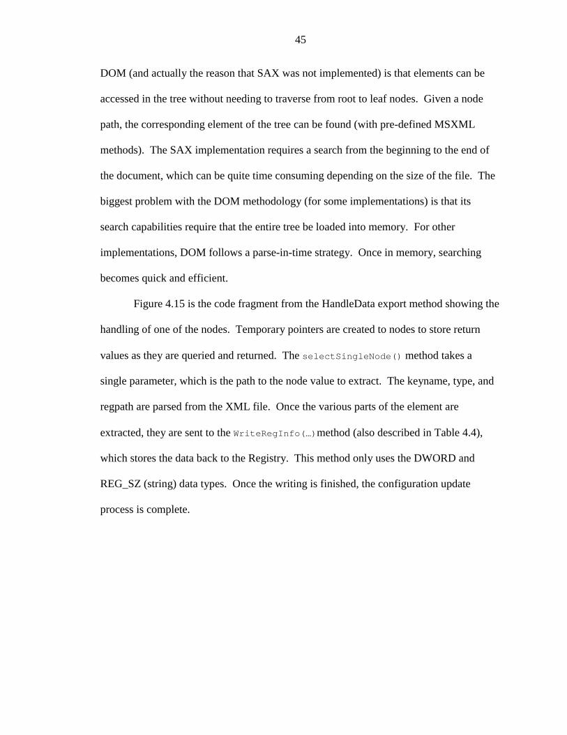
45
DOM (and actually the reason that SAX was not implemented) is that elements can be
accessed in the tree without needing to traverse from root to leaf nodes. Given a node
path, the corresponding element of the tree can be found (with pre-defined MSXML
methods). The SAX implementation requires a search from the beginning to the end of
the document, which can be quite time consuming depending on the size of the file. The
biggest problem with the DOM methodology (for some implementations) is that its
search capabilities require that the entire tree be loaded into memory. For other
implementations, DOM follows a parse-in-time strategy. Once in memory, searching
becomes quick and efficient.
Figure 4.15 is the code fragment from the HandleData export method showing the
handling of one of the nodes. Temporary pointers are created to nodes to store return
values as they are queried and returned. The selectSingleNode() method takes a
single parameter, which is the path to the node value to extract. The keyname, type, and
regpath are parsed from the XML file. Once the various parts of the element are
extracted, they are sent to the WriteRegInfo(…)method (also described in Table 4.4),
which stores the data back to the Registry. This method only uses the DWORD and
REG_SZ (string) data types. Once the writing is finished, the configuration update
process is complete.
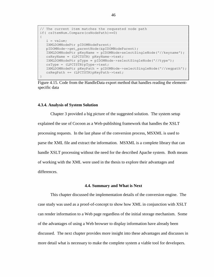
46
// The current item matches the requested node pathif( csItemNum.Compare(csNodePath)==0){
i = value;IXMLDOMNodePtr pIDOMNodeParent;pIDOMNode->get_parentNode(&pIDOMNodeParent);IXMLDOMNodePtr pKeyName = pIDOMNode>selectSingleNode("//keyname");csKeyName = (LPCTSTR) pKeyName->text;IXMLDOMNodePtr pType = pIDOMNode->selectSingleNode("//type");csType = (LPCTSTR)pType->text;IXMLDOMNodePtr pKeyPath = pIDOMNode->selectSingleNode("//regpath");csRegPath += (LPCTSTR)pKeyPath->text;
}
Figure 4.15. Code from the HandleData export method that handles reading the element-specific data
4.3.4. Analysis of System Solution
Chapter 3 provided a big picture of the suggested solution. The system setup
explained the use of Cocoon as a Web-publishing framework that handles the XSLT
processing requests. In the last phase of the conversion process, MSXML is used to
parse the XML file and extract the information. MSXML is a complete library that can
handle XSLT processing without the need for the described Apache system. Both means
of working with the XML were used in the thesis to explore their advantages and
differences.
4.4. Summary and What is Next
This chapter discussed the implementation details of the conversion engine. The
case study was used as a proof-of-concept to show how XML in conjunction with XSLT
can render information to a Web page regardless of the initial storage mechanism. Some
of the advantages of using a Web browser to display information have already been
discussed. The next chapter provides more insight into these advantages and discusses in
more detail what is necessary to make the complete system a viable tool for developers.
47
CHAPTER 5ENHANCEMENTS AND CONCLUSIONS
Over the next five years, virtually every major application will either becompletely Web-based, or at a minimum have a Web frontend. At thesame time, users are demanding more functionality, and marketingdepartments are demanding more flexibility in look and feel. The resulthas been the rise of the Web artist… [McL00,http://www.oreilly.com/catalog/javaxml/chapter/ch09.html]
This thesis explores the problem of integrated data and presentation. Legacy code
systems are becoming obsolete as the world progresses away from local standalone
executables and toward client Web-based applications. Chapter 1 presents an
introduction to the problem using the foresight of many authors to express the continued
interest in making the user interface more intuitive. The conversion engine, a proposed
solution to the problem, was introduced in a high-level. Chapter 2 serves as a technical
overview of the technologies used to create the conversion engine. It also provides
insight to the case study, the RJE Configuration Utility, as a tool to analyze the proposed
solution. Chapters 3 and 4 contain the bulk of the implementation details of the
conversion engine. This chapter will consider some enhancements to the process and
present some recommendations for future research.
5.1. Complete System
In the discussion thus far, the case study, the Command’s tab of the RJE
Configuration Utility, is presented as an example of the use of the conversion engine.
This example shows how the process can be used for a specific purpose. As mentioned
in the discussion of each of the implementation modules, values and parameters were
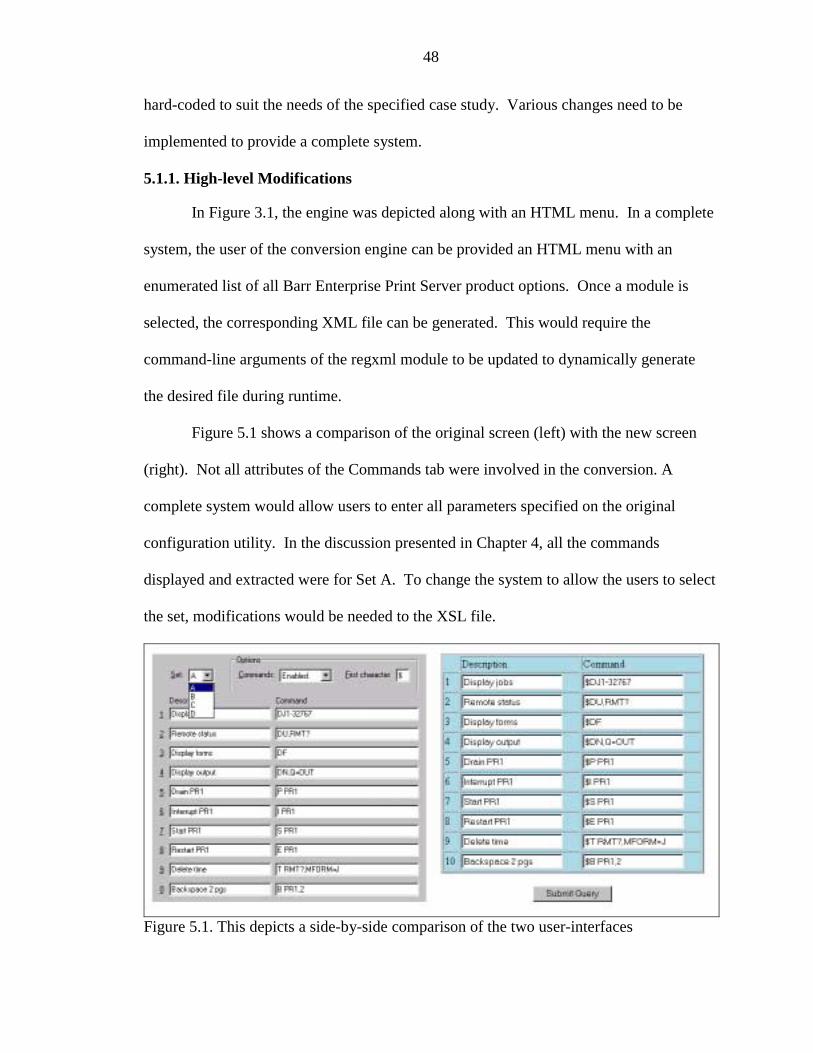
48
hard-coded to suit the needs of the specified case study. Various changes need to be
implemented to provide a complete system.
5.1.1. High-level Modifications
In Figure 3.1, the engine was depicted along with an HTML menu. In a complete
system, the user of the conversion engine can be provided an HTML menu with an
enumerated list of all Barr Enterprise Print Server product options. Once a module is
selected, the corresponding XML file can be generated. This would require the
command-line arguments of the regxml module to be updated to dynamically generate
the desired file during runtime.
Figure 5.1 shows a comparison of the original screen (left) with the new screen
(right). Not all attributes of the Commands tab were involved in the conversion. A
complete system would allow users to enter all parameters specified on the original
configuration utility. In the discussion presented in Chapter 4, all the commands
displayed and extracted were for Set A. To change the system to allow the users to select
the set, modifications would be needed to the XSL file.
Figure 5.1. This depicts a side-by-side comparison of the two user-interfaces
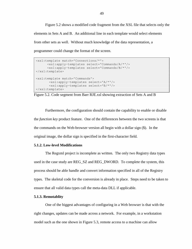
49
Figure 5.2 shows a modified code fragment from the XSL file that selects only the
elements in Sets A and B. An additional line in each template would select elements
from other sets as well. Without much knowledge of the data representation, a
programmer could change the format of the screen.
<xsl:template match="Connections/*"><xsl:apply-templates select="Commands/A/*"/><xsl:apply-templates select="Commands/B/*"/>
</xsl:template>
<xsl:template match="Commands"><xsl:apply-templates select="A/*"/><xsl:apply-templates select="B/*"/>
</xsl:template>
Figure 5.2. Code segment from Barr RJE.xsl showing extraction of Sets A and B
Furthermore, the configuration should contain the capability to enable or disable
the function key product feature. One of the differences between the two screens is that
the commands on the Web-browser version all begin with a dollar sign ($). In the
original image, the dollar sign is specified in the first-character field.
5.1.2. Low-level Modifications
The Regxml project is incomplete as written. The only two Registry data types
used in the case study are REG_SZ and REG_DWORD. To complete the system, this
process should be able handle and convert information specified in all of the Registry
types. The skeletal code for the conversion is already in place. Steps need to be taken to
ensure that all valid data types call the meta-data DLL if applicable.
5.1.3. Remotablity
One of the biggest advantages of configuring in a Web browser is that with the
right changes, updates can be made across a network. For example, in a workstation
model such as the one shown in Figure 5.3, remote access to a machine can allow
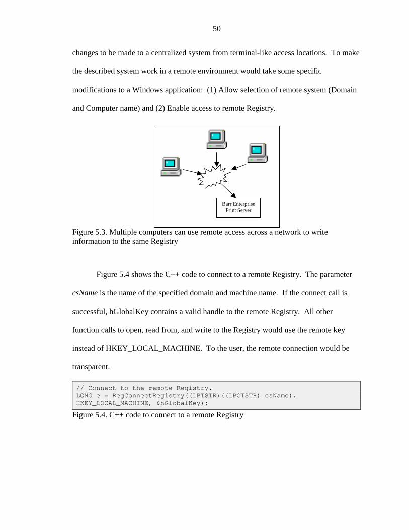
50
changes to be made to a centralized system from terminal-like access locations. To make
the described system work in a remote environment would take some specific
modifications to a Windows application: (1) Allow selection of remote system (Domain
and Computer name) and (2) Enable access to remote Registry.
Figure 5.3. Multiple computers can use remote access across a network to writeinformation to the same Registry
Figure 5.4 shows the C++ code to connect to a remote Registry. The parameter
csName is the name of the specified domain and machine name. If the connect call is
successful, hGlobalKey contains a valid handle to the remote Registry. All other
function calls to open, read from, and write to the Registry would use the remote key
instead of HKEY_LOCAL_MACHINE. To the user, the remote connection would be
transparent.
// Connect to the remote Registry.LONG e = RegConnectRegistry((LPTSTR)((LPCTSTR) csName),HKEY_LOCAL_MACHINE, &hGlobalKey);
Figure 5.4. C++ code to connect to a remote Registry
Barr EnterprisePrint Server
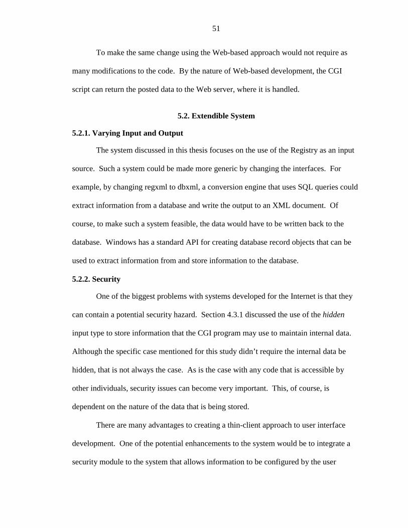
51
To make the same change using the Web-based approach would not require as
many modifications to the code. By the nature of Web-based development, the CGI
script can return the posted data to the Web server, where it is handled.
5.2. Extendible System
5.2.1. Varying Input and Output
The system discussed in this thesis focuses on the use of the Registry as an input
source. Such a system could be made more generic by changing the interfaces. For
example, by changing regxml to dbxml, a conversion engine that uses SQL queries could
extract information from a database and write the output to an XML document. Of
course, to make such a system feasible, the data would have to be written back to the
database. Windows has a standard API for creating database record objects that can be
used to extract information from and store information to the database.
5.2.2. Security
One of the biggest problems with systems developed for the Internet is that they
can contain a potential security hazard. Section 4.3.1 discussed the use of the hidden
input type to store information that the CGI program may use to maintain internal data.
Although the specific case mentioned for this study didn’t require the internal data be
hidden, that is not always the case. As is the case with any code that is accessible by
other individuals, security issues can become very important. This, of course, is
dependent on the nature of the data that is being stored.
There are many advantages to creating a thin-client approach to user interface
development. One of the potential enhancements to the system would be to integrate a
security module to the system that allows information to be configured by the user

52
depending on the current user rights. For example, a modification to the system would
allow the user to only change the description (but not change the command) whereas an
administrator would have privileges to change all the fields.
5.3. Conclusions
5.3.1. From MFC to Web Browser
Earlier, MFC was introduced as the C++ class library of object-oriented wrappers
for the Window API. The 6.0 version of the foundation classes provides programmers
with nearly 200 classes representing pre-written objects. One of the most important
architectures, sometimes described as the cornerstone of application development using
MFC, is the document/view architecture [Pro99, p. 12]. It is interesting to try and
understand how an application built with such a framework could be ported to the Web.
Even dialog-based applications (usually used for configuration purposes) must be
presented completely differently on a Web browser.
Figure 5.5 shows a segment of another property page of the RJE Configuration
Utility. The top image shows the logon data input field is not available if the logon type
is Formatted, while the bottom image shows that the field is available if the logon type is
Character Coded. This type of available/unavailable options changing dynamically is a
feature of the way Windows applications have been developed using MFC. If the same
information were presented on a Web page, it would have to be expressed differently.
The notion of enabling or disabling a field based on prior selection is something users
have become accustomed to with a Windows application. How hard is it to transform
this feature to a Web-based application? What are the steps necessary to do so?
53
There is no argument that Web-based development is different from Windows
applications on many levels. Despite its advantages, it may not be the appropriate
medium for all applications. Determining what is best for the end user is key to the
success of any product. The transition from one visual form to another will take time.
The important point to keep in mind is that as people and technologies change, the
development methodology should change accordingly.
Figure 5.5. A portion of the configuration screen that is enabled or disabled based onselection
Until now this thesis has discussed one potential solution to Web-enable an
existing product. Features and benefits of the system have been discussed intermittently
throughout the discussion. One of the biggest advantages of Web-enabling a system is
that the thin-client becomes readily portable.
5.3.2. The Perfect Solution?
The recommended conversion engine, although paving the way to a more flexible
solution, has its disadvantages. The Barr RJE.xsl file generated in the case study was
neither large nor unmanageable. A more complete system, however, would require
hundreds of lines of XSLT to extract information from the corresponding XML files.
Writing the necessary XSLT can become quite cumbersome. It is therefore important to
keep in mind that one of most important advantages of the proposed system is that it

54
allows the abstraction to be made at a much higher level. While MFC programming,
with its complicated integration of message passing and handling with user controls,
provides a solution at the key-stoke level, the XML and XSLT combination provide the
integration closer to the browser and therefore closer to the user-level.
5.3.3. Final Word on Usability
The usability of your application’s design is not just a philosophicalnicety for your consideration; it is essential to the success of yourapplication. [Sti99, p. 4]
A design methodology recommended for Windows application development
describes a design cycle with the following important phases:
• Design – The initial work of the developer; often described to be the most important
stage because it can make or break the system.
• Prototype – In an ideal development environment, all software projects would be
prototyped before being written. A design prototype can often indicate the flaws of
the design.
• Test – Usability testing is one way of determining potential flaws before it is too late.
By having novice users try out a system, many of the confusing aspects of the design
can be pinpointed.
• Iterate – Any “how to develop” guide would suggest that the design, prototype, test
cycle should be done as many times as it takes to get the system right [Sti99].
55
5.3.4. Summary
Because software truly is malleable far beyond any other media, it has thepotential to go well beyond the expectations of even the wildest dreamer.All it requires is the judicious partnering of interaction design withprogramming. [Coo99, p. 17]
The technologies introduced into the Web-world have served as the key to the
separation of data from presentation. Using a case study, the thesis explored the use of
XML and XSL to create a wedge in the currently integrated system that would allow the
design and the implementation to be separated. Although Windows development has
evolved into a highly flexible technique for intricate designs, it requires that the
developer have the skill set of a design artist. By creating the abstraction suggested by
the conversion engine, the data and presentation, while separated, can be managed at a
much higher level. As the trends continue to change, hopefully the technologies can mold
the software, so that it may reach user expectations.
56
GLOSSARY
API Stands for Application programming interface.A set of interfaces that allow software tointeract with another application. Forexample, the Win32 API is a set of interfacesto reference the Windows 32-bit operatingsystem.
attributes XML attributes are name/value pairsassociated with an element. They are definedwithin the element tag and are specifiedfollowing an equal sign and within quotes,such as <author fname =“John” lname=“Doe”></author>.
BEPS Stands for Barr Enterprise Print Server. Aproduct developed by Barr Systems, Inc.which facilitates host connectivity from allprinting sources.
CSS Stands for Cascading Style Sheet. One of thetypes of style sheets applied to an XMLdocument. A simple means for specifyingstyles such as font and color.
CDATA A section of an XML document that containsany information that should not be processedby the XML parser. This is the best way ofnesting XML data within XML data.
CGI Stands for Common Gateway Interface. Astandard format for sending information (in theform of a name-value pair) between the serverand script.
Cocoon A project as part of Apache. It is “a 100%pure Java publishing framework that relies onnew W3C technologies (such as DOM, XML,and XSL) to provide web content.”
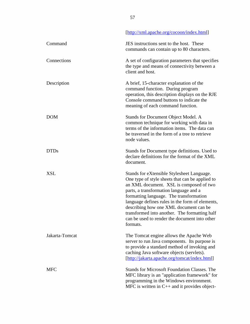
57
[http://xml.apache.org/cocoon/index.html]
Command JES instructions sent to the host. Thesecommands can contain up to 80 characters.
Connections A set of configuration parameters that specifiesthe type and means of connectivity between aclient and host.
Description A brief, 15-character explanation of thecommand function. During programoperation, this description displays on the RJEConsole command buttons to indicate themeaning of each command function.
DOM Stands for Document Object Model. Acommon technique for working with data interms of the information items. The data canbe traversed in the form of a tree to retrievenode values.
DTDs Stands for Document type definitions. Used todeclare definitions for the format of the XMLdocument.
XSL Stands for eXtensible Stylesheet Language.One type of style sheets that can be applied toan XML document. XSL is composed of twoparts, a transformation language and aformatting language. The transformationlanguage defines rules in the form of elements,describing how one XML document can betransformed into another. The formatting halfcan be used to render the document into otherformats.
Jakarta-Tomcat The Tomcat engine allows the Apache Webserver to run Java components. Its purpose isto provide a standard method of invoking andcaching Java software objects (servlets).[http://jakarta.apache.org/tomcat/index.html]
MFC Stands for Microsoft Foundation Classes. TheMFC library is an "application framework" forprogramming in the Windows environment.MFC is written in C++ and it provides object-

58
oriented wrappers for managing windows,menus, and dialog boxes.
MSXML A Microsoft-developed set of interfaces forparsing XML documents.
Options Additional configuration parameters for theCommands Tab of the RJE ConfigurationUtility.
Registry A global storage mechanism (a database) in theWindows environment.
Registry Editor An editor that uses a tree-like structure torepresent information stored in the Registry.
RJE Stands for Remote Job Entry. A subset of theBarr Enterprise Print Server. BARR/RJEallows the computer on which it resides tocommunicate with the mainframe by emulatinga device that uses the standardcommunications protocol.
RJE Configuration Utility A standalone MFC application that presentsusers with the opportunity to enter severalscreens of RJE configuration information.
Sets A grouping for the forty commands labeledone of A, B, C, and D. Each group (or set)contains default values for the first four JES2printers.
SAX Stands for Simple API for XML. A commontechnique for working with data in terms of theinformation items. SAX is used when theinterest is in parsing an XML document frombeginning to end. This can be done becauseSAX parses the XML file element by element.
SQL Stands for Structured Query Language. Alanguage used to query databases.
Style sheets Specifies how the XML documents should berendered on the output device. Currently, thereare two types of style sheets supported byXML, Cascading Style Sheet (CSS) and
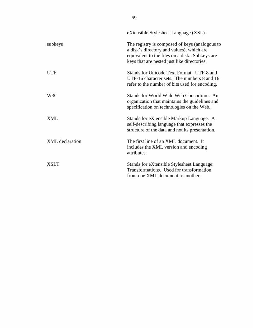
59
eXtensible Stylesheet Language (XSL).
subkeys The registry is composed of keys (analogous toa disk’s directory and values), which areequivalent to the files on a disk. Subkeys arekeys that are nested just like directories.
UTF Stands for Unicode Text Format. UTF-8 andUTF-16 character sets. The numbers 8 and 16refer to the number of bits used for encoding.
W3C Stands for World Wide Web Consortium. Anorganization that maintains the guidelines andspecification on technologies on the Web.
XML Stands for eXtensible Markup Language. Aself-describing language that expresses thestructure of the data and not its presentation.
XML declaration The first line of an XML document. Itincludes the XML version and encodingattributes.
XSLT Stands for eXtensible Stylesheet Language:Transformations. Used for transformationfrom one XML document to another.
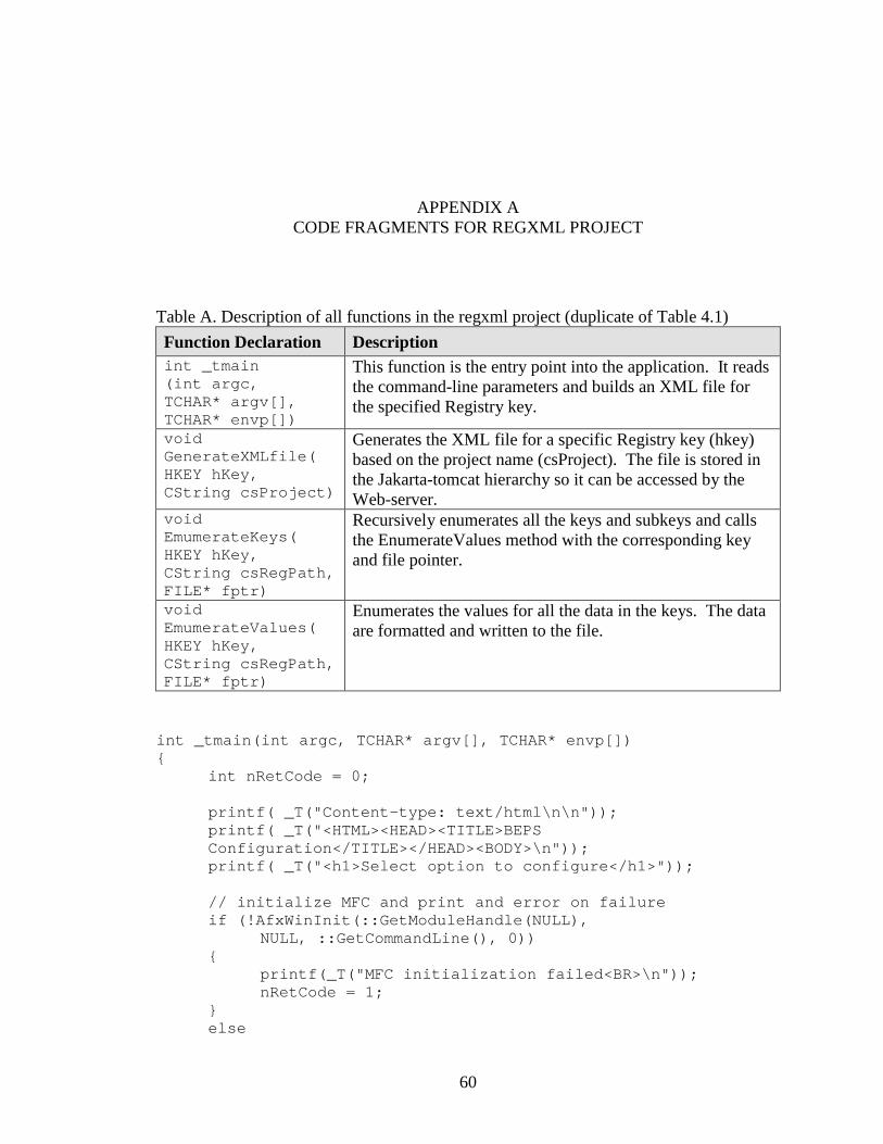
60
APPENDIX ACODE FRAGMENTS FOR REGXML PROJECT
Table A. Description of all functions in the regxml project (duplicate of Table 4.1)Function Declaration Descriptionint _tmain(int argc,TCHAR* argv[],TCHAR* envp[])
This function is the entry point into the application. It readsthe command-line parameters and builds an XML file forthe specified Registry key.
voidGenerateXMLfile(HKEY hKey,CString csProject)
Generates the XML file for a specific Registry key (hkey)based on the project name (csProject). The file is stored inthe Jakarta-tomcat hierarchy so it can be accessed by theWeb-server.
voidEmumerateKeys(HKEY hKey,CString csRegPath,FILE* fptr)
Recursively enumerates all the keys and subkeys and callsthe EnumerateValues method with the corresponding keyand file pointer.
voidEmumerateValues(HKEY hKey,CString csRegPath,FILE* fptr)
Enumerates the values for all the data in the keys. The dataare formatted and written to the file.
int _tmain(int argc, TCHAR* argv[], TCHAR* envp[]){
int nRetCode = 0;
printf( _T("Content-type: text/html\n\n"));printf( _T("<HTML><HEAD><TITLE>BEPSConfiguration</TITLE></HEAD><BODY>\n"));printf( _T("<h1>Select option to configure</h1>"));
// initialize MFC and print and error on failureif (!AfxWinInit(::GetModuleHandle(NULL),
NULL, ::GetCommandLine(), 0)){
printf(_T("MFC initialization failed<BR>\n"));nRetCode = 1;
}else
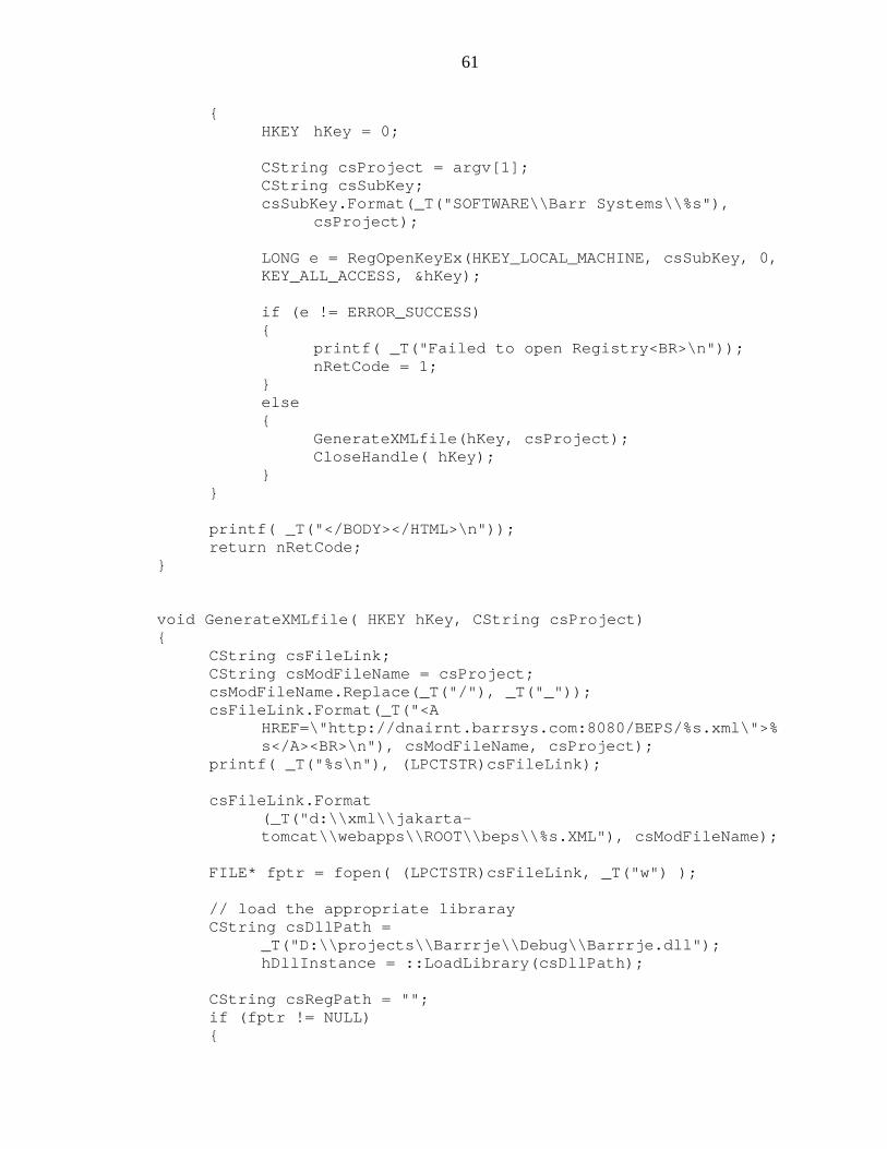
61
{HKEY hKey = 0;
CString csProject = argv[1];CString csSubKey;csSubKey.Format(_T("SOFTWARE\\Barr Systems\\%s"),
csProject);
LONG e = RegOpenKeyEx(HKEY_LOCAL_MACHINE, csSubKey, 0,KEY_ALL_ACCESS, &hKey);
if (e != ERROR_SUCCESS){
printf( _T("Failed to open Registry<BR>\n"));nRetCode = 1;
}else{
GenerateXMLfile(hKey, csProject);CloseHandle( hKey);
}}
printf( _T("</BODY></HTML>\n"));return nRetCode;
}
void GenerateXMLfile( HKEY hKey, CString csProject){
CString csFileLink;CString csModFileName = csProject;csModFileName.Replace(_T("/"), _T("_"));csFileLink.Format(_T("<A
HREF=\"http://dnairnt.barrsys.com:8080/BEPS/%s.xml\">%s</A><BR>\n"), csModFileName, csProject);
printf( _T("%s\n"), (LPCTSTR)csFileLink);
csFileLink.Format(_T("d:\\xml\\jakarta-tomcat\\webapps\\ROOT\\beps\\%s.XML"), csModFileName);
FILE* fptr = fopen( (LPCTSTR)csFileLink, _T("w") );
// load the appropriate librarayCString csDllPath =
_T("D:\\projects\\Barrrje\\Debug\\Barrrje.dll");hDllInstance = ::LoadLibrary(csDllPath);
CString csRegPath = "";if (fptr != NULL){
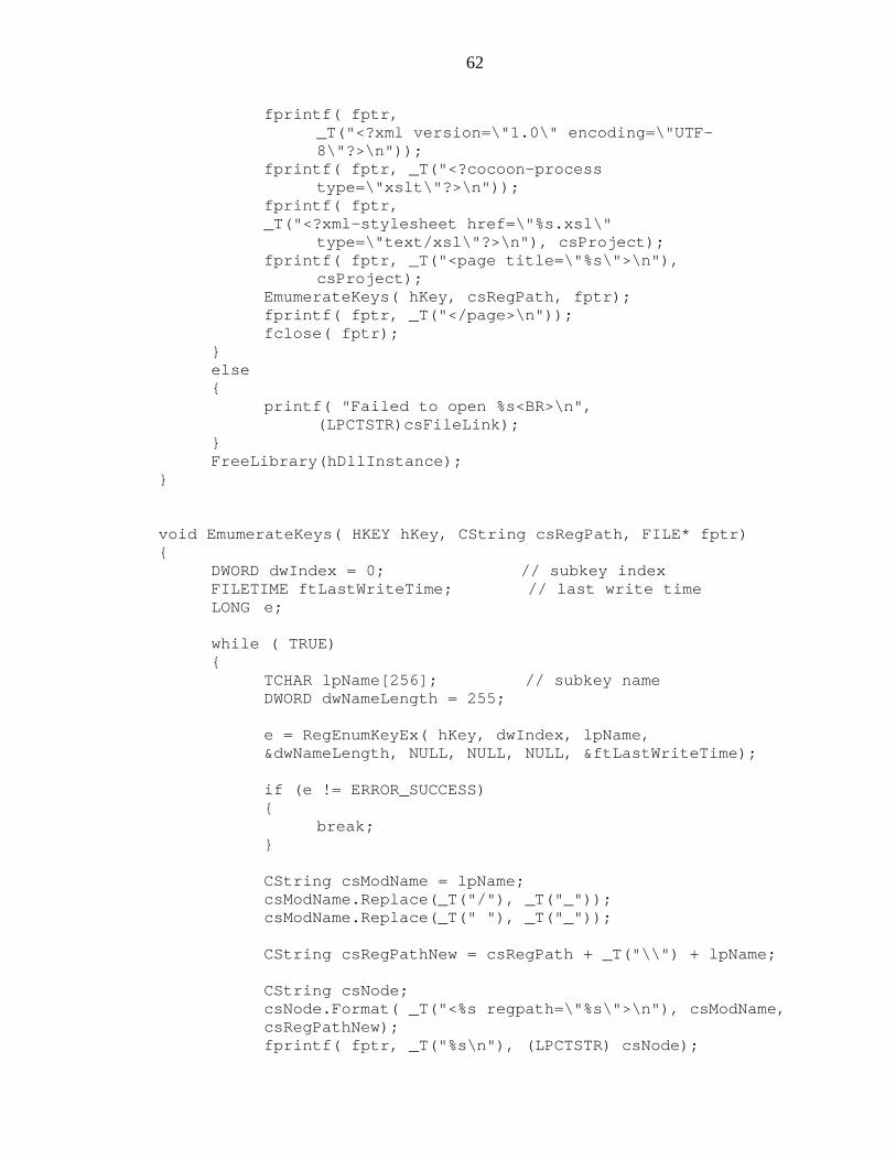
62
fprintf( fptr,_T("<?xml version=\"1.0\" encoding=\"UTF-8\"?>\n"));
fprintf( fptr, _T("<?cocoon-processtype=\"xslt\"?>\n"));
fprintf( fptr,_T("<?xml-stylesheet href=\"%s.xsl\"
type=\"text/xsl\"?>\n"), csProject);fprintf( fptr, _T("<page title=\"%s\">\n"),
csProject);EmumerateKeys( hKey, csRegPath, fptr);fprintf( fptr, _T("</page>\n"));fclose( fptr);
}else{
printf( "Failed to open %s<BR>\n",(LPCTSTR)csFileLink);
}FreeLibrary(hDllInstance);
}
void EmumerateKeys( HKEY hKey, CString csRegPath, FILE* fptr){
DWORD dwIndex = 0; // subkey indexFILETIME ftLastWriteTime; // last write timeLONG e;
while ( TRUE){
TCHAR lpName[256]; // subkey nameDWORD dwNameLength = 255;
e = RegEnumKeyEx( hKey, dwIndex, lpName,&dwNameLength, NULL, NULL, NULL, &ftLastWriteTime);
if (e != ERROR_SUCCESS){
break;}
CString csModName = lpName;csModName.Replace(_T("/"), _T("_"));csModName.Replace(_T(" "), _T("_"));
CString csRegPathNew = csRegPath + _T("\\") + lpName;
CString csNode;csNode.Format( _T("<%s regpath=\"%s\">\n"), csModName,csRegPathNew);fprintf( fptr, _T("%s\n"), (LPCTSTR) csNode);
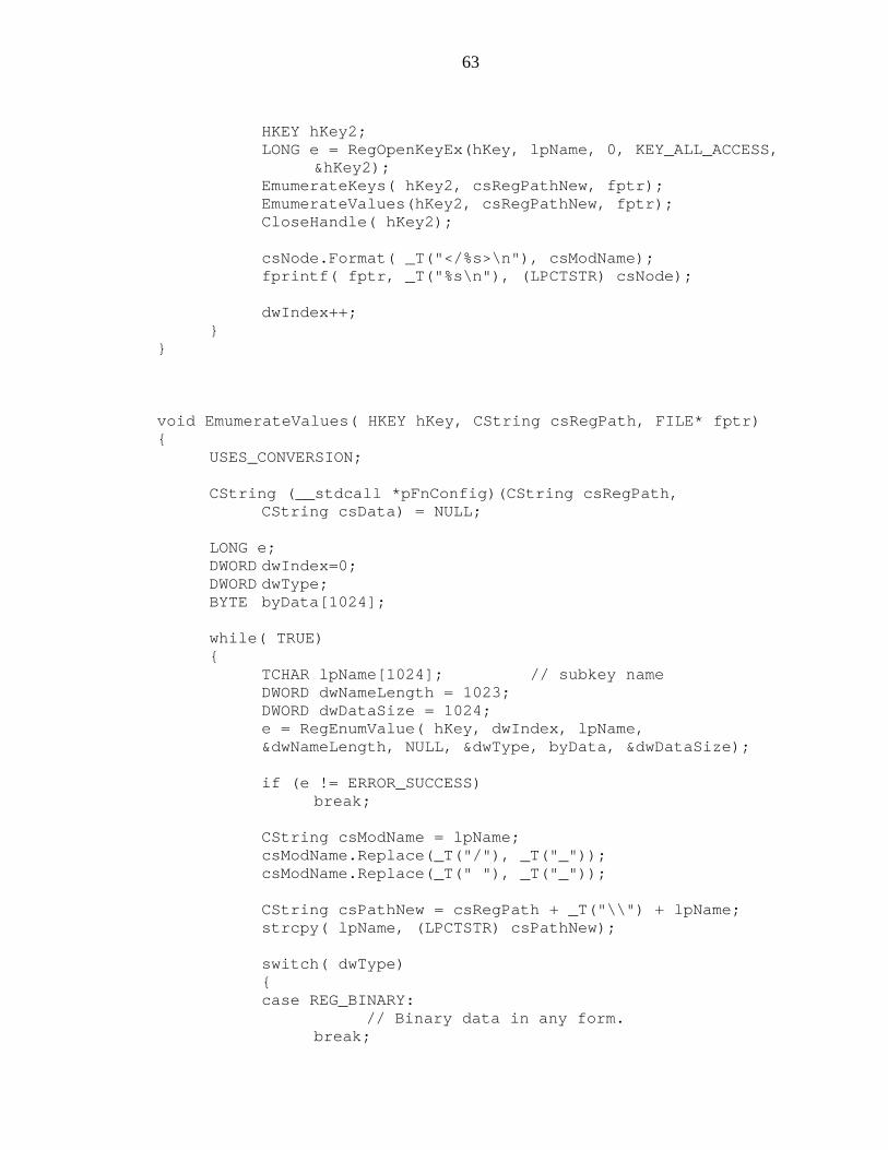
63
HKEY hKey2;LONG e = RegOpenKeyEx(hKey, lpName, 0, KEY_ALL_ACCESS,
&hKey2);EmumerateKeys( hKey2, csRegPathNew, fptr);EmumerateValues(hKey2, csRegPathNew, fptr);CloseHandle( hKey2);
csNode.Format( _T("</%s>\n"), csModName);fprintf( fptr, _T("%s\n"), (LPCTSTR) csNode);
dwIndex++;}
}
void EmumerateValues( HKEY hKey, CString csRegPath, FILE* fptr){
USES_CONVERSION;
CString (__stdcall *pFnConfig)(CString csRegPath,CString csData) = NULL;
LONG e;DWORD dwIndex=0;DWORD dwType;BYTE byData[1024];
while( TRUE){
TCHAR lpName[1024]; // subkey nameDWORD dwNameLength = 1023;DWORD dwDataSize = 1024;e = RegEnumValue( hKey, dwIndex, lpName,&dwNameLength, NULL, &dwType, byData, &dwDataSize);
if (e != ERROR_SUCCESS)break;
CString csModName = lpName;csModName.Replace(_T("/"), _T("_"));csModName.Replace(_T(" "), _T("_"));
CString csPathNew = csRegPath + _T("\\") + lpName;strcpy( lpName, (LPCTSTR) csPathNew);
switch( dwType){case REG_BINARY:
// Binary data in any form.break;
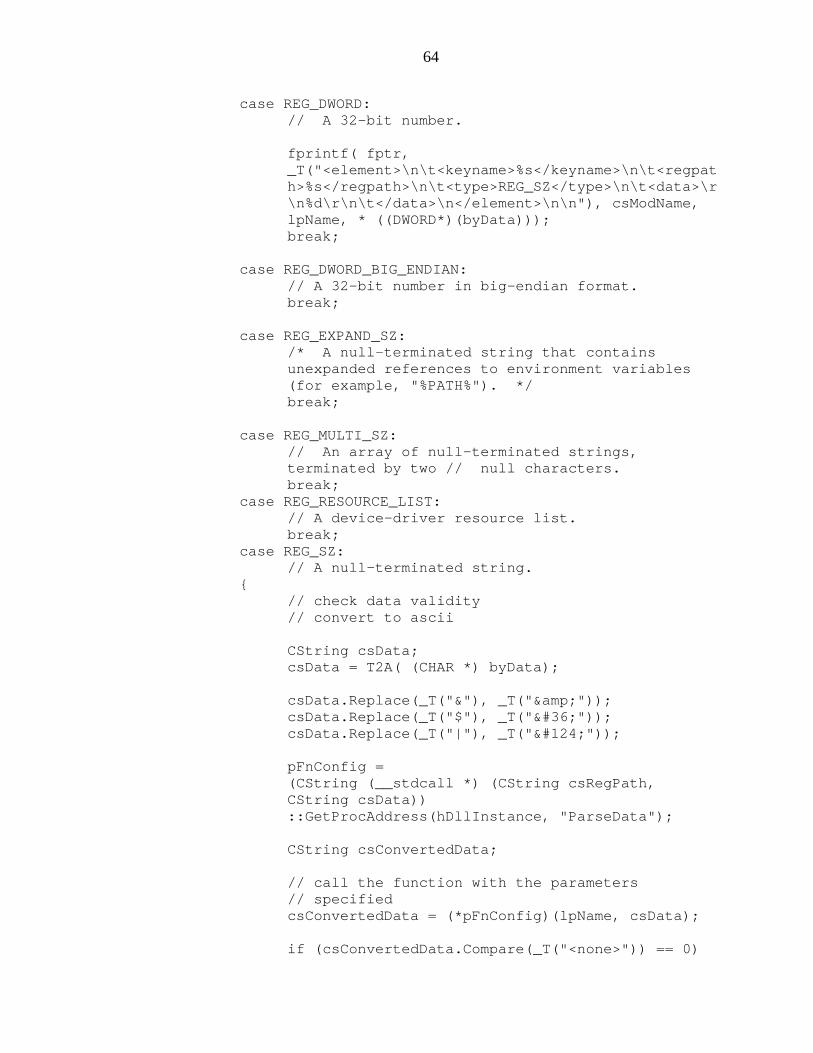
64
case REG_DWORD:// A 32-bit number.
fprintf( fptr,_T("<element>\n\t<keyname>%s</keyname>\n\t<regpath>%s</regpath>\n\t<type>REG_SZ</type>\n\t<data>\r\n%d\r\n\t</data>\n</element>\n\n"), csModName,lpName, * ((DWORD*)(byData)));break;
case REG_DWORD_BIG_ENDIAN:// A 32-bit number in big-endian format.break;
case REG_EXPAND_SZ:/* A null-terminated string that containsunexpanded references to environment variables(for example, "%PATH%"). */break;
case REG_MULTI_SZ:// An array of null-terminated strings,terminated by two // null characters.break;
case REG_RESOURCE_LIST:// A device-driver resource list.break;
case REG_SZ:// A null-terminated string.
{// check data validity// convert to ascii
CString csData;csData = T2A( (CHAR *) byData);
csData.Replace(_T("&"), _T("&"));csData.Replace(_T("$"), _T("$"));csData.Replace(_T("|"), _T("|"));
pFnConfig =(CString (__stdcall *) (CString csRegPath,CString csData))::GetProcAddress(hDllInstance, "ParseData");
CString csConvertedData;
// call the function with the parameters// specifiedcsConvertedData = (*pFnConfig)(lpName, csData);
if (csConvertedData.Compare(_T("<none>")) == 0)
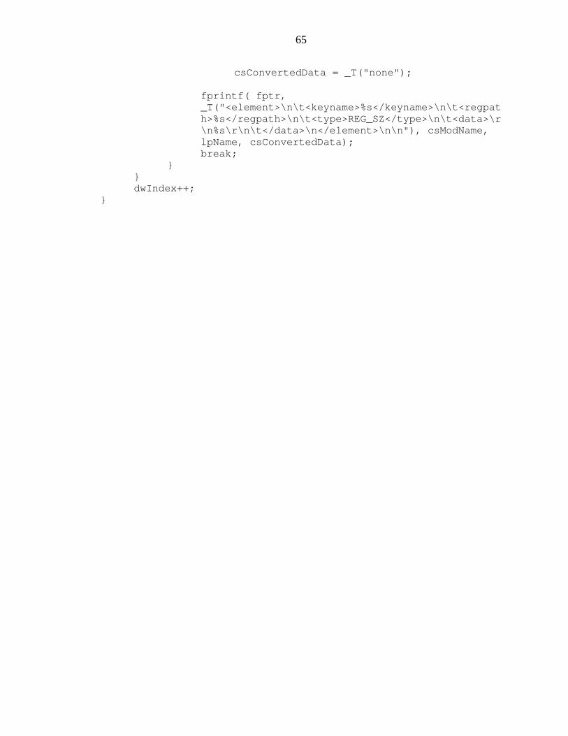
65
csConvertedData = _T("none");
fprintf( fptr,_T("<element>\n\t<keyname>%s</keyname>\n\t<regpath>%s</regpath>\n\t<type>REG_SZ</type>\n\t<data>\r\n%s\r\n\t</data>\n</element>\n\n"), csModName,lpName, csConvertedData);break;
}}dwIndex++;
}
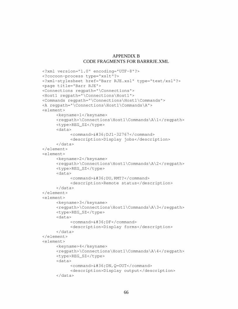
66
APPENDIX BCODE FRAGMENTS FOR BARRRJE.XML
<?xml version="1.0" encoding="UTF-8"?><?cocoon-process type="xslt"?><?xml-stylesheet href="Barr RJE.xsl" type="text/xsl"?><page title="Barr RJE"><Connections regpath="\Connections"><Host1 regpath="\Connections\Host1"><Commands regpath="\Connections\Host1\Commands"><A regpath="\Connections\Host1\Commands\A"><element>
<keyname>1</keyname><regpath>\Connections\Host1\Commands\A\1</regpath><type>REG_SZ</type><data>
<command>$DJ1-32767</command><description>Display jobs</description>
</data></element><element>
<keyname>2</keyname><regpath>\Connections\Host1\Commands\A\2</regpath><type>REG_SZ</type><data>
<command>$DU,RMT?</command><description>Remote status</description>
</data></element><element>
<keyname>3</keyname><regpath>\Connections\Host1\Commands\A\3</regpath><type>REG_SZ</type><data>
<command>$DF</command><description>Display forms</description>
</data></element><element>
<keyname>4</keyname><regpath>\Connections\Host1\Commands\A\4</regpath><type>REG_SZ</type><data>
<command>$DN,Q=OUT</command><description>Display output</description>
</data>
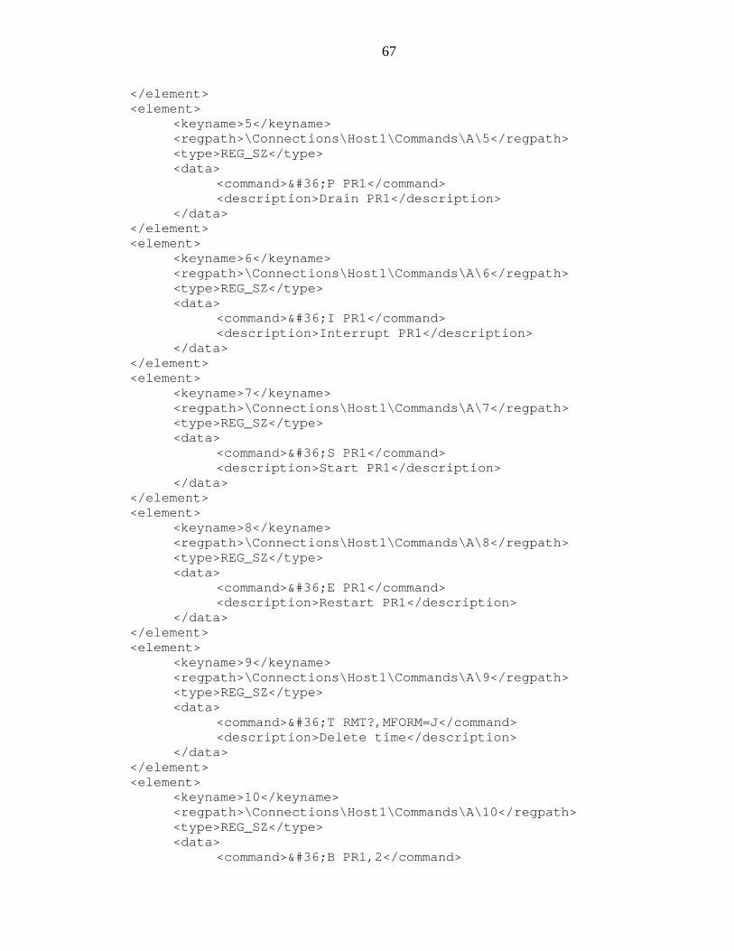
67
</element><element>
<keyname>5</keyname><regpath>\Connections\Host1\Commands\A\5</regpath><type>REG_SZ</type><data>
<command>$P PR1</command><description>Drain PR1</description>
</data></element><element>
<keyname>6</keyname><regpath>\Connections\Host1\Commands\A\6</regpath><type>REG_SZ</type><data>
<command>$I PR1</command><description>Interrupt PR1</description>
</data></element><element>
<keyname>7</keyname><regpath>\Connections\Host1\Commands\A\7</regpath><type>REG_SZ</type><data>
<command>$S PR1</command><description>Start PR1</description>
</data></element><element>
<keyname>8</keyname><regpath>\Connections\Host1\Commands\A\8</regpath><type>REG_SZ</type><data>
<command>$E PR1</command><description>Restart PR1</description>
</data></element><element>
<keyname>9</keyname><regpath>\Connections\Host1\Commands\A\9</regpath><type>REG_SZ</type><data>
<command>$T RMT?,MFORM=J</command><description>Delete time</description>
</data></element><element>
<keyname>10</keyname><regpath>\Connections\Host1\Commands\A\10</regpath><type>REG_SZ</type><data>
<command>$B PR1,2</command>
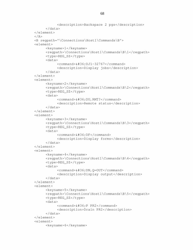
68
<description>Backspace 2 pgs</description></data>
</element></A><B regpath="\Connections\Host1\Commands\B"><element>
<keyname>1</keyname><regpath>\Connections\Host1\Commands\B\1</regpath><type>REG_SZ</type><data>
<command>$DJ1-32767</command><description>Display jobs</description>
</data></element><element>
<keyname>2</keyname><regpath>\Connections\Host1\Commands\B\2</regpath><type>REG_SZ</type><data>
<command>$DU,RMT?</command><description>Remote status</description>
</data></element><element>
<keyname>3</keyname><regpath>\Connections\Host1\Commands\B\3</regpath><type>REG_SZ</type><data>
<command>$DF</command><description>Display forms</description>
</data></element><element>
<keyname>4</keyname><regpath>\Connections\Host1\Commands\B\4</regpath><type>REG_SZ</type><data>
<command>$DN,Q=OUT</command><description>Display output</description>
</data></element><element>
<keyname>5</keyname><regpath>\Connections\Host1\Commands\B\5</regpath><type>REG_SZ</type><data>
<command>$P PR2</command><description>Drain PR2</description>
</data></element><element>
<keyname>6</keyname>

69
<regpath>\Connections\Host1\Commands\B\6</regpath><type>REG_SZ</type><data>
<command>$I PR2</command><description>Interrupt PR2</description>
</data></element><element>
<keyname>7</keyname><regpath>\Connections\Host1\Commands\B\7</regpath><type>REG_SZ</type><data>
<command>$S PR2</command><description>Start PR2</description>
</data></element><element>
<keyname>8</keyname><regpath>\Connections\Host1\Commands\B\8</regpath><type>REG_SZ</type><data>
<command>$E PR2</command><description>Restart PR2</description>
</data></element><element>
<keyname>9</keyname><regpath>\Connections\Host1\Commands\B\9</regpath><type>REG_SZ</type><data>
<command>$T RMT?,MFORM=J</command><description>Delete time</description>
</data></element><element>
<keyname>10</keyname><regpath>\Connections\Host1\Commands\B\10</regpath><type>REG_SZ</type><data>
<command>$B PR2,2</command><description>Backspace 2 pgs</description>
</data></element></B><C regpath="\Connections\Host1\Commands\C"><element>
<keyname>1</keyname><regpath>\Connections\Host1\Commands\C\1</regpath><type>REG_SZ</type><data>
<command>$DJ1-32767</command>
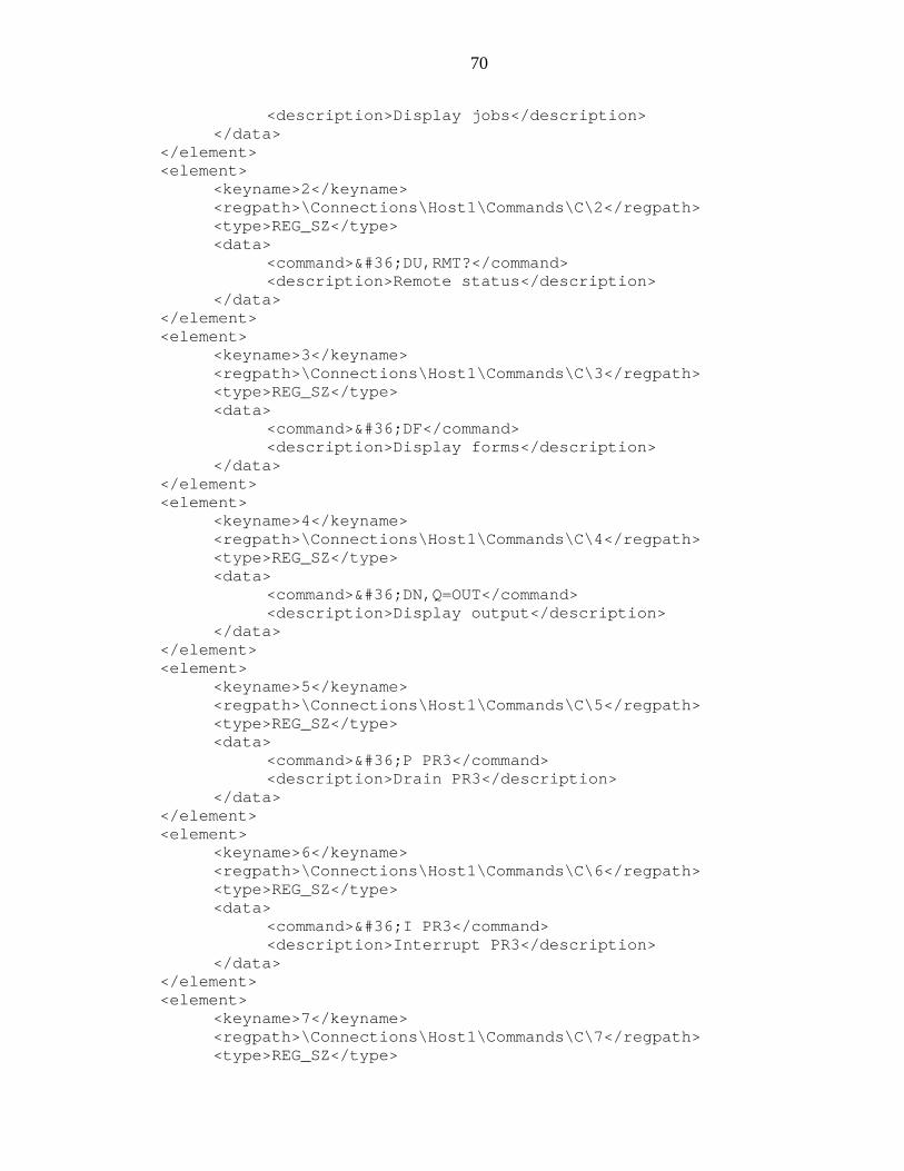
70
<description>Display jobs</description></data>
</element><element>
<keyname>2</keyname><regpath>\Connections\Host1\Commands\C\2</regpath><type>REG_SZ</type><data>
<command>$DU,RMT?</command><description>Remote status</description>
</data></element><element>
<keyname>3</keyname><regpath>\Connections\Host1\Commands\C\3</regpath><type>REG_SZ</type><data>
<command>$DF</command><description>Display forms</description>
</data></element><element>
<keyname>4</keyname><regpath>\Connections\Host1\Commands\C\4</regpath><type>REG_SZ</type><data>
<command>$DN,Q=OUT</command><description>Display output</description>
</data></element><element>
<keyname>5</keyname><regpath>\Connections\Host1\Commands\C\5</regpath><type>REG_SZ</type><data>
<command>$P PR3</command><description>Drain PR3</description>
</data></element><element>
<keyname>6</keyname><regpath>\Connections\Host1\Commands\C\6</regpath><type>REG_SZ</type><data>
<command>$I PR3</command><description>Interrupt PR3</description>
</data></element><element>
<keyname>7</keyname><regpath>\Connections\Host1\Commands\C\7</regpath><type>REG_SZ</type>
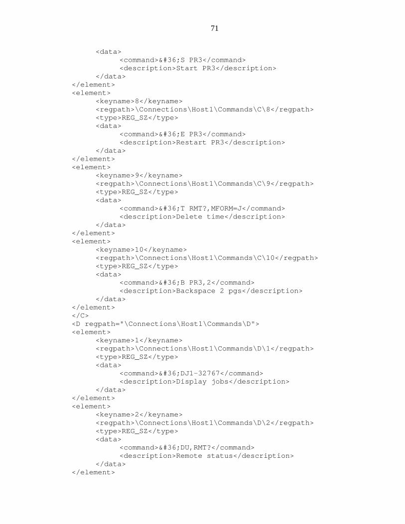
71
<data><command>$S PR3</command><description>Start PR3</description>
</data></element><element>
<keyname>8</keyname><regpath>\Connections\Host1\Commands\C\8</regpath><type>REG_SZ</type><data>
<command>$E PR3</command><description>Restart PR3</description>
</data></element><element>
<keyname>9</keyname><regpath>\Connections\Host1\Commands\C\9</regpath><type>REG_SZ</type><data>
<command>$T RMT?,MFORM=J</command><description>Delete time</description>
</data></element><element>
<keyname>10</keyname><regpath>\Connections\Host1\Commands\C\10</regpath><type>REG_SZ</type><data>
<command>$B PR3,2</command><description>Backspace 2 pgs</description>
</data></element></C><D regpath="\Connections\Host1\Commands\D"><element>
<keyname>1</keyname><regpath>\Connections\Host1\Commands\D\1</regpath><type>REG_SZ</type><data>
<command>$DJ1-32767</command><description>Display jobs</description>
</data></element><element>
<keyname>2</keyname><regpath>\Connections\Host1\Commands\D\2</regpath><type>REG_SZ</type><data>
<command>$DU,RMT?</command><description>Remote status</description>
</data></element>
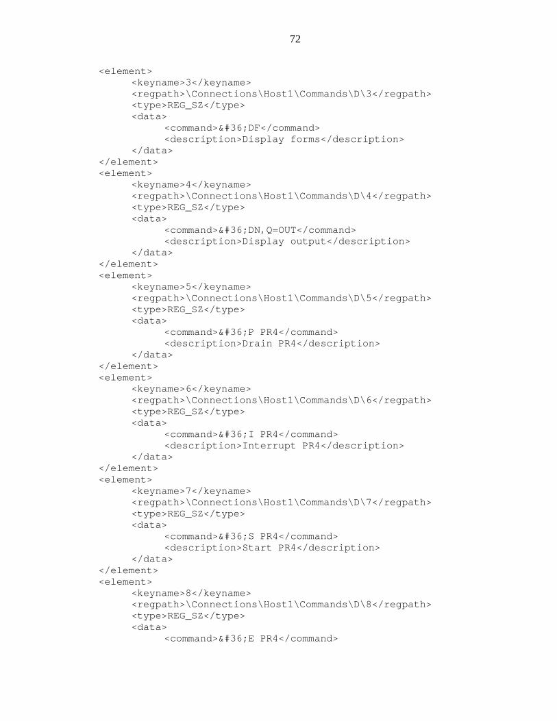
72
<element><keyname>3</keyname><regpath>\Connections\Host1\Commands\D\3</regpath><type>REG_SZ</type><data>
<command>$DF</command><description>Display forms</description>
</data></element><element>
<keyname>4</keyname><regpath>\Connections\Host1\Commands\D\4</regpath><type>REG_SZ</type><data>
<command>$DN,Q=OUT</command><description>Display output</description>
</data></element><element>
<keyname>5</keyname><regpath>\Connections\Host1\Commands\D\5</regpath><type>REG_SZ</type><data>
<command>$P PR4</command><description>Drain PR4</description>
</data></element><element>
<keyname>6</keyname><regpath>\Connections\Host1\Commands\D\6</regpath><type>REG_SZ</type><data>
<command>$I PR4</command><description>Interrupt PR4</description>
</data></element><element>
<keyname>7</keyname><regpath>\Connections\Host1\Commands\D\7</regpath><type>REG_SZ</type><data>
<command>$S PR4</command><description>Start PR4</description>
</data></element><element>
<keyname>8</keyname><regpath>\Connections\Host1\Commands\D\8</regpath><type>REG_SZ</type><data>
<command>$E PR4</command>
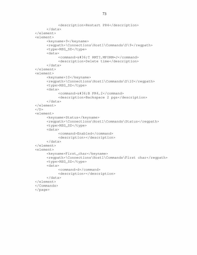
73
<description>Restart PR4</description></data>
</element><element>
<keyname>9</keyname><regpath>\Connections\Host1\Commands\D\9</regpath><type>REG_SZ</type><data>
<command>$T RMT?,MFORM=J</command><description>Delete time</description>
</data></element><element>
<keyname>10</keyname><regpath>\Connections\Host1\Commands\D\10</regpath><type>REG_SZ</type><data>
<command>$B PR4,2</command><description>Backspace 2 pgs</description>
</data></element></D><element>
<keyname>Status</keyname><regpath>\Connections\Host1\Commands\Status</regpath><type>REG_SZ</type><data>
<command>Enabled</command><description></description>
</data></element><element>
<keyname>First_char</keyname><regpath>\Connections\Host1\Commands\First char</regpath><type>REG_SZ</type><data>
<command>d</command><description></description>
</data></element></Commands></page>
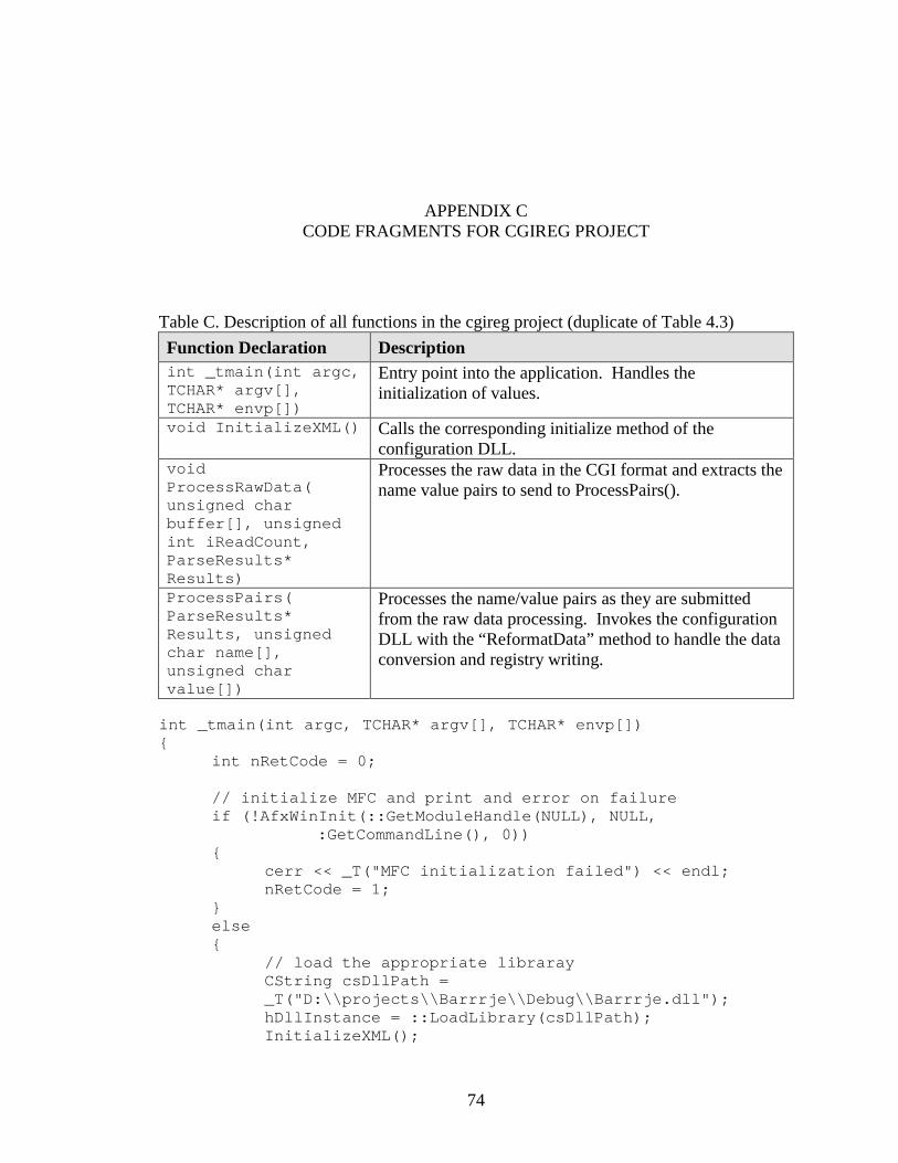
74
APPENDIX CCODE FRAGMENTS FOR CGIREG PROJECT
Table C. Description of all functions in the cgireg project (duplicate of Table 4.3)Function Declaration Descriptionint _tmain(int argc,TCHAR* argv[],TCHAR* envp[])
Entry point into the application. Handles theinitialization of values.
void InitializeXML() Calls the corresponding initialize method of theconfiguration DLL.
voidProcessRawData(unsigned charbuffer[], unsignedint iReadCount,ParseResults*Results)
Processes the raw data in the CGI format and extracts thename value pairs to send to ProcessPairs().
ProcessPairs(ParseResults*Results, unsignedchar name[],unsigned charvalue[])
Processes the name/value pairs as they are submittedfrom the raw data processing. Invokes the configurationDLL with the “ReformatData” method to handle the dataconversion and registry writing.
int _tmain(int argc, TCHAR* argv[], TCHAR* envp[]){
int nRetCode = 0;
// initialize MFC and print and error on failureif (!AfxWinInit(::GetModuleHandle(NULL), NULL,
:GetCommandLine(), 0)){
cerr << _T("MFC initialization failed") << endl;nRetCode = 1;
}else{
// load the appropriate librarayCString csDllPath =_T("D:\\projects\\Barrrje\\Debug\\Barrrje.dll");hDllInstance = ::LoadLibrary(csDllPath);InitializeXML();
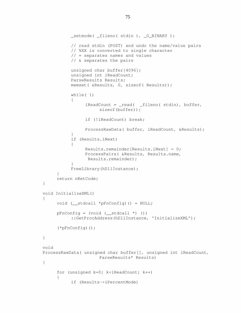
75
_setmode( _fileno( stdin ), _O_BINARY );
// read stdin (POST) and undo the name/value pairs// %XX is converted to single character// = separates names and values// & separates the pairs
unsigned char buffer[4096];unsigned int iReadCount;ParseResults Results;memset( &Results, 0, sizeof( Results));
while( 1){
iReadCount = _read( _fileno( stdin), buffer,sizeof(buffer));
if (!iReadCount) break;
ProcessRawData( buffer, iReadCount, &Results);}if (Results.iNext){
Results.remainder[Results.iNext] = 0;ProcessPairs( &Results, Results.name,Results.remainder);
}FreeLibrary(hDllInstance);
}return nRetCode;
}
void InitializeXML(){
void (__stdcall *pFnConfig)() = NULL;
pFnConfig = (void (__stdcall *) ())::GetProcAddress(hDllInstance, "InitializeXML");
(*pFnConfig)();
}
voidProcessRawData( unsigned char buffer[], unsigned int iReadCount,
ParseResults* Results){
for (unsigned k=0; k<iReadCount; k++){
if (Results->iPercentMode)
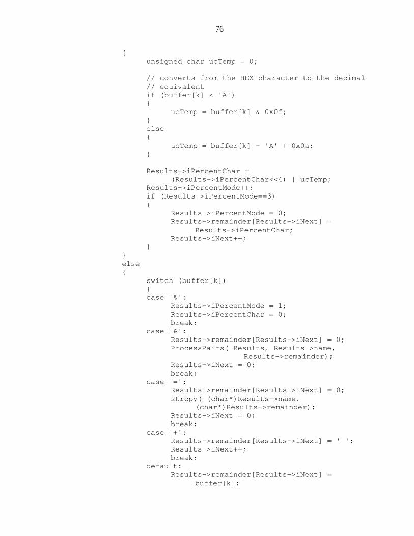
76
{unsigned char ucTemp = 0;
// converts from the HEX character to the decimal// equivalentif (buffer[k] < 'A'){
ucTemp = buffer[k] & 0x0f;}else{
ucTemp = buffer[k] - 'A' + 0x0a;}
Results->iPercentChar =(Results->iPercentChar<<4) | ucTemp;
Results->iPercentMode++;if (Results->iPercentMode==3){
Results->iPercentMode = 0;Results->remainder[Results->iNext] =
Results->iPercentChar;Results->iNext++;
}}else{
switch (buffer[k]){case '%':
Results->iPercentMode = 1;Results->iPercentChar = 0;break;
case '&':Results->remainder[Results->iNext] = 0;ProcessPairs( Results, Results->name,
Results->remainder);Results->iNext = 0;break;
case '=':Results->remainder[Results->iNext] = 0;strcpy( (char*)Results->name,
(char*)Results->remainder);Results->iNext = 0;break;
case '+':Results->remainder[Results->iNext] = ' ';Results->iNext++;break;
default:Results->remainder[Results->iNext] =
buffer[k];
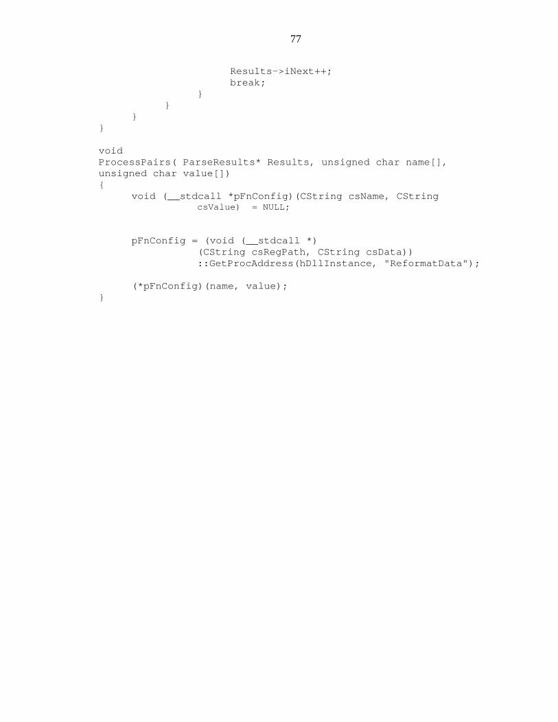
77
Results->iNext++;break;
}}
}}
voidProcessPairs( ParseResults* Results, unsigned char name[],unsigned char value[]){
void (__stdcall *pFnConfig)(CString csName, CStringcsValue) = NULL;
pFnConfig = (void (__stdcall *)(CString csRegPath, CString csData))::GetProcAddress(hDllInstance, "ReformatData");
(*pFnConfig)(name, value);}
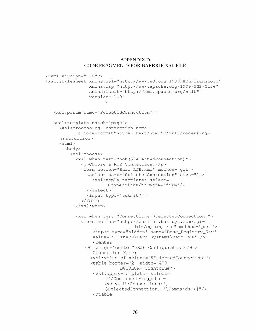
78
APPENDIX DCODE FRAGMENTS FOR BARRRJE.XSL FILE
<?xml version="1.0"?><xsl:stylesheet xmlns:xsl="http://www.w3.org/1999/XSL/Transform"
xmlns:xsp="http://www.apache.org/1999/XSP/Core"xmlns:lxslt="http://xml.apache.org/xslt"version="1.0"
>
<xsl:param name="SelectedConnection"/>
<xsl:template match="page"><xsl:processing-instruction name=
"cocoon-format">type="text/html"</xsl:processing-instruction><html><body><xsl:choose><xsl:when test="not($SelectedConnection)"><p>Choose a RJE Connection:</p><form action="Barr RJE.xml" method="get"><select name="SelectedConnection" size="1"><xsl:apply-templates select=
"Connections/*" mode="form"/></select><input type="submit"/>
</form></xsl:when>
<xsl:when test="Connections[$SelectedConnection]"><form action="http://dnairnt.barrsys.com/cgi-
bin/cgireg.exe" method="post"><input type="hidden" name="Base_Registry_Key"value="SOFTWARE\Barr Systems\Barr RJE" /><center>
<H1 align="center">RJE Configuration</H1>Connection Name:<xsl:value-of select="$SelectedConnection"/><table border="2" width="400"
BGCOLOR="lightblue"><xsl:apply-templates select=
"//Commands[@regpath =concat('\Connections\',$SelectedConnection, '\Commands')]"/>
</table>
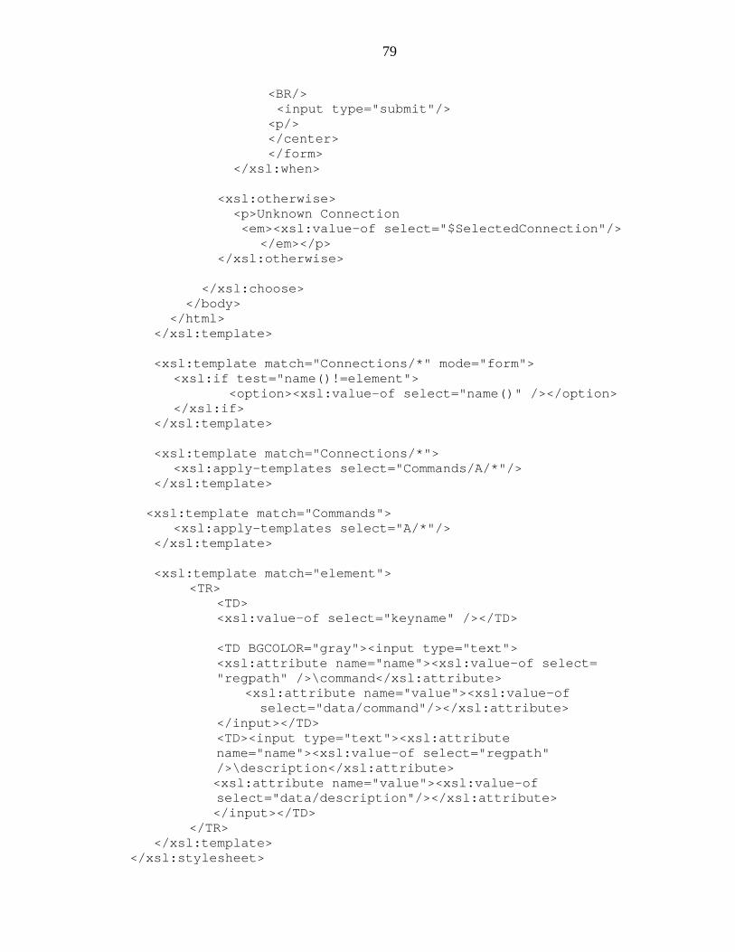
79
<BR/><input type="submit"/>
<p/></center></form>
</xsl:when>
<xsl:otherwise><p>Unknown Connection<em><xsl:value-of select="$SelectedConnection"/>
</em></p></xsl:otherwise>
</xsl:choose></body>
</html></xsl:template>
<xsl:template match="Connections/*" mode="form"><xsl:if test="name()!=element">
<option><xsl:value-of select="name()" /></option></xsl:if>
</xsl:template>
<xsl:template match="Connections/*"><xsl:apply-templates select="Commands/A/*"/>
</xsl:template>
<xsl:template match="Commands"><xsl:apply-templates select="A/*"/>
</xsl:template>
<xsl:template match="element"><TR>
<TD><xsl:value-of select="keyname" /></TD>
<TD BGCOLOR="gray"><input type="text"><xsl:attribute name="name"><xsl:value-of select="regpath" />\command</xsl:attribute>
<xsl:attribute name="value"><xsl:value-ofselect="data/command"/></xsl:attribute>
</input></TD><TD><input type="text"><xsl:attributename="name"><xsl:value-of select="regpath"/>\description</xsl:attribute><xsl:attribute name="value"><xsl:value-ofselect="data/description"/></xsl:attribute></input></TD>
</TR></xsl:template>
</xsl:stylesheet>
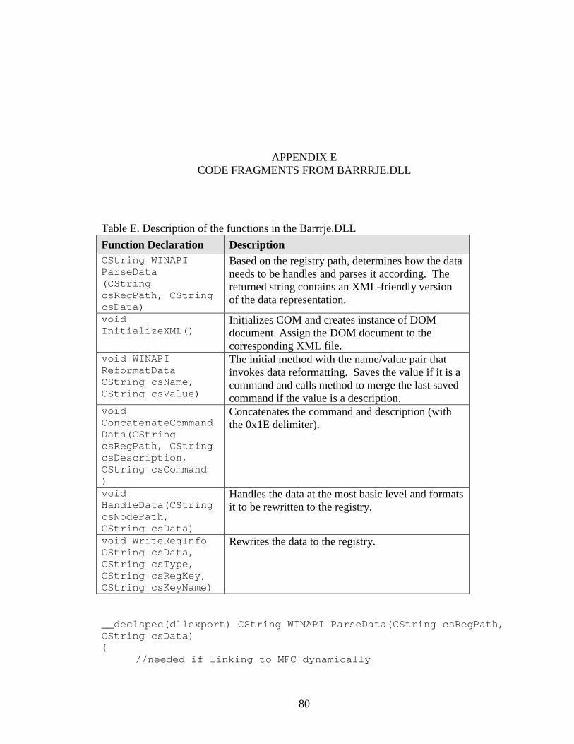
80
APPENDIX ECODE FRAGMENTS FROM BARRRJE.DLL
Table E. Description of the functions in the Barrrje.DLLFunction Declaration DescriptionCString WINAPIParseData(CStringcsRegPath, CStringcsData)
Based on the registry path, determines how the dataneeds to be handles and parses it according. Thereturned string contains an XML-friendly versionof the data representation.
voidInitializeXML()
Initializes COM and creates instance of DOMdocument. Assign the DOM document to thecorresponding XML file.
void WINAPIReformatDataCString csName,CString csValue)
The initial method with the name/value pair thatinvokes data reformatting. Saves the value if it is acommand and calls method to merge the last savedcommand if the value is a description.
voidConcatenateCommandData(CStringcsRegPath, CStringcsDescription,CString csCommand)
Concatenates the command and description (withthe 0x1E delimiter).
voidHandleData(CStringcsNodePath,CString csData)
Handles the data at the most basic level and formatsit to be rewritten to the registry.
void WriteRegInfoCString csData,CString csType,CString csRegKey,CString csKeyName)
Rewrites the data to the registry.
__declspec(dllexport) CString WINAPI ParseData(CString csRegPath,CString csData){
//needed if linking to MFC dynamically
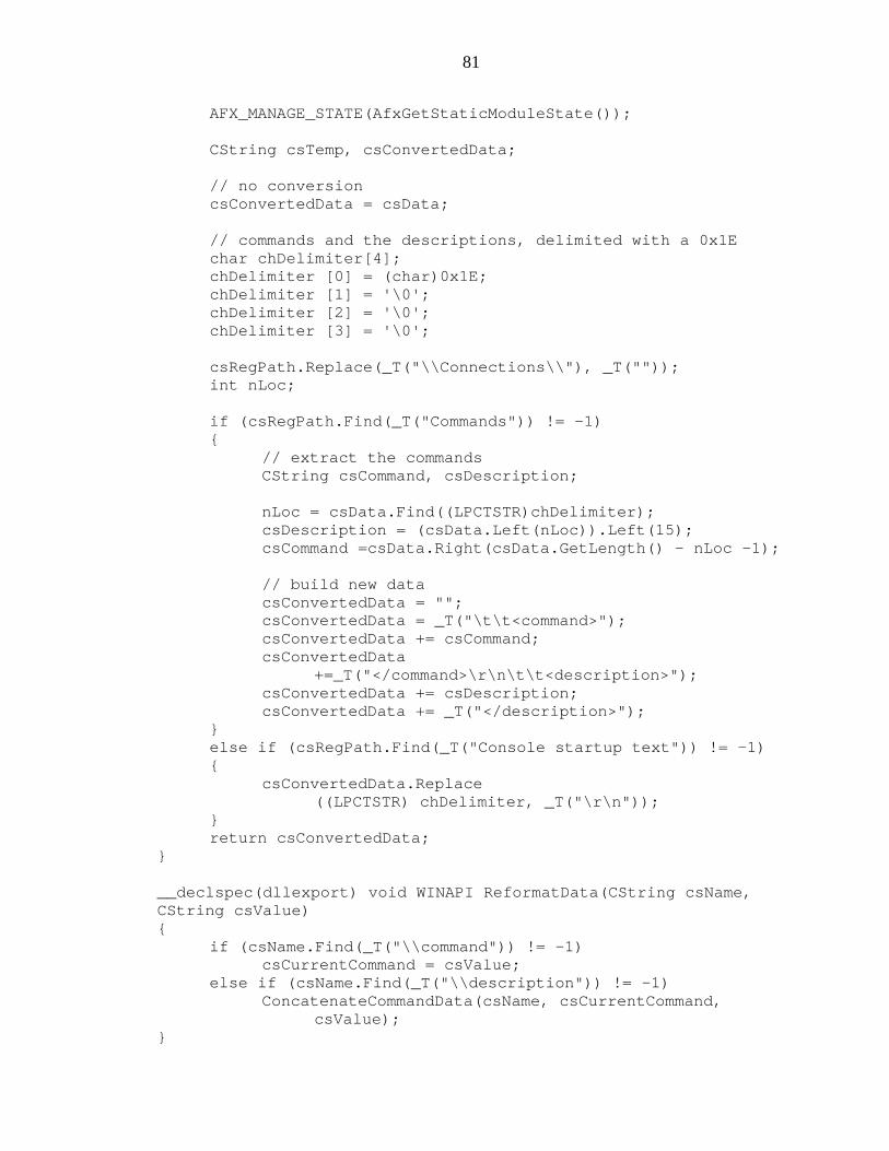
81
AFX_MANAGE_STATE(AfxGetStaticModuleState());
CString csTemp, csConvertedData;
// no conversioncsConvertedData = csData;
// commands and the descriptions, delimited with a 0x1Echar chDelimiter[4];chDelimiter [0] = (char)0x1E;chDelimiter [1] = '\0';chDelimiter [2] = '\0';chDelimiter [3] = '\0';
csRegPath.Replace(_T("\\Connections\\"), _T(""));int nLoc;
if (csRegPath.Find(_T("Commands")) != -1){
// extract the commandsCString csCommand, csDescription;
nLoc = csData.Find((LPCTSTR)chDelimiter);csDescription = (csData.Left(nLoc)).Left(15);csCommand =csData.Right(csData.GetLength() - nLoc -1);
// build new datacsConvertedData = "";csConvertedData = _T("\t\t<command>");csConvertedData += csCommand;csConvertedData
+=_T("</command>\r\n\t\t<description>");csConvertedData += csDescription;csConvertedData += _T("</description>");
}else if (csRegPath.Find(_T("Console startup text")) != -1){
csConvertedData.Replace((LPCTSTR) chDelimiter, _T("\r\n"));
}return csConvertedData;
}
__declspec(dllexport) void WINAPI ReformatData(CString csName,CString csValue){
if (csName.Find(_T("\\command")) != -1)csCurrentCommand = csValue;
else if (csName.Find(_T("\\description")) != -1)ConcatenateCommandData(csName, csCurrentCommand,
csValue);}
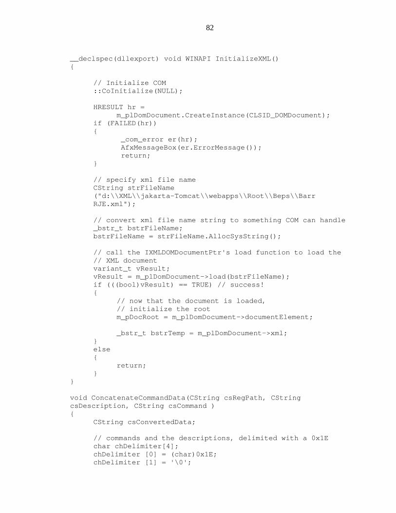
82
__declspec(dllexport) void WINAPI InitializeXML(){
// Initialize COM::CoInitialize(NULL);
HRESULT hr =m_plDomDocument.CreateInstance(CLSID_DOMDocument);
if (FAILED(hr)){
_com_error er(hr);AfxMessageBox(er.ErrorMessage());return;
}
// specify xml file nameCString strFileName("d:\\XML\\jakarta-Tomcat\\webapps\\Root\\Beps\\BarrRJE.xml");
// convert xml file name string to something COM can handle_bstr_t bstrFileName;bstrFileName = strFileName.AllocSysString();
// call the IXMLDOMDocumentPtr's load function to load the// XML documentvariant_t vResult;vResult = m_plDomDocument->load(bstrFileName);if (((bool)vResult) == TRUE) // success!{
// now that the document is loaded,// initialize the rootm_pDocRoot = m_plDomDocument->documentElement;
_bstr_t bstrTemp = m_plDomDocument->xml;}else{
return;}
}
void ConcatenateCommandData(CString csRegPath, CStringcsDescription, CString csCommand ){
CString csConvertedData;
// commands and the descriptions, delimited with a 0x1Echar chDelimiter[4];chDelimiter [0] = (char)0x1E;chDelimiter [1] = '\0';
83
chDelimiter [2] = '\0';chDelimiter [3] = '\0';
csConvertedData.Format(_T("%s%s%s"),csCommand,(LPCTSTR) chDelimiter, csDescription);
// strip off the description from the regpathcsRegPath.Replace(_T("\\description"), _T(""));HandleData(csRegPath, csConvertedData);
}
void HandleData(CString csNodePath, CString csData){
// send the root to the DisplayChildren function//DisplayChildren(m_pDocRoot);IXMLDOMNodeListPtr pCur =m_pDocRoot->selectNodes("//page//Connections//test//Commands//A//element//regpath"
);
CString csKeyName, csType, csRegPath;csRegPath = _T("Software\\Barr Systems\\Barr RJE");
long value = 0L;pCur->get_length(&value);for (int i = 0;i <value;i++) {
BSTR bstrItemText;IXMLDOMNodePtr pIDOMNode;pCur->get_item(i, &pIDOMNode);pIDOMNode->get_text(&bstrItemText);CString csItemNum;_bstr_t bstr( bstrItemText, TRUE );csItemNum = (char*)bstr;
// The current item matches the requested node pathif( csItemNum.Compare(csNodePath)==0){
i = value;IXMLDOMNodePtr pIDOMNodeParent;pIDOMNode->get_parentNode(&pIDOMNodeParent);IXMLDOMNodePtr pKeyName =
pIDOMNode->selectSingleNode("//keyname");csKeyName = (LPCTSTR) pKeyName->text;IXMLDOMNodePtr pType =
pIDOMNode->selectSingleNode("//type");csType = (LPCTSTR)pType->text;IXMLDOMNodePtr pKeyPath =
pIDOMNode->selectSingleNode("//regpath");csRegPath += (LPCTSTR)pKeyPath->text;
}}
84
int nLoc = csRegPath.ReverseFind('\\');csRegPath = csRegPath.Left(nLoc);WriteRegInfo(csData, csType, csRegPath, csKeyName);
}
void WriteRegInfo(CString csData, CString csType, CStringcsRegKey, CString csKeyName){
HKEY hKey;LONG e = RegOpenKeyEx(HKEY_LOCAL_MACHINE, csRegKey, 0,KEY_ALL_ACCESS, &hKey);LONG lResult;
if (csType.CompareNoCase(_T("REG_SZ")) == 0){
DWORD dwSize = (csData.GetLength() + 1 ) *sizeof(TCHAR);
lResult = RegSetValueEx(hKey, csKeyName, 0, REG_SZ,(BYTE*)((LPCTSTR) csData), dwSize);
}else if (csType.CompareNoCase(_T("REG_DWORD")) == 0){
char * pszBuf;pszBuf = (char *)&csData;lResult = RegSetValueEx(hKey, csKeyName, 0, REG_DWORD,
(CONST BYTE *) pszBuf, sizeof (DWORD) );}RegCloseKey(hKey); }
85
LIST OF REFERENCES
[Box00] Box, Don, Aaron Skonnard, and John Lam. Essential XML: BeyondMarkup. Boston, Massachusetts: Addison-Wesley, 2000.
[Cas98] Castro, Elizabeth. HTML for the World Wide Web. Berkeley, California:Peachpit Press, 1998.
[Coo99] Cooper, Alan. The Inmates are Running the Asylum. Indianapolis,Indiana: Sams, 1999.
[Har99] Harold, Elliotte Rusty. XML Bible. Foster City, California: IDG BookWorldwide, Inc., 1999.
[Her97] Herrmann, Eric. Teach Yourself CGI Programming with Perl 5 in aWeek. Second Edition. Indianapolis, Indiana: Sams, 1997.
[How96] Howlette, Virginia. Visual Interface Design for Windows. New York:Wiley Computer Publishing, 1996.
[Kay00] Kay, Michael. XSLT: Programmer’s Reference. Chicago, Illinois: WroxPress, 2000.
[Kru97] Kruglinski, David J. Inside Visual C++: Fourth Edition. Redmond,Washington: Microsoft Press, 1997.
[Mar00] Marchal, Benoît. XML: By Example. Indianapolis, Indiana: Que, 2000.
[Mcl00] McLaughlin, Brett. JAVA and XML. Cambridge, Massachusetts:O’Reilly and Associates, 2000
[Pro99] Prosise, Jeff. Programming Windows with MFC: Second Edition.Redmond, Washington: Microsoft Press, 1999.
[Sol00] Solomon, David A. and Mark E. Russinovich. Inside Microsoft Windows2000: Third Edition. Redmond, Washington: Microsoft Press, 2000.
[Sti99] Stickney, Sally Ed. Microsoft Windows User Experience. Redmond,Washington: Microsoft Press, 1999.

86
BIOGRAPHICAL SKETCH
Deepa Nair was born in Trivandrum, Kerala (India), on January 29, 1979. She
lived in Nairobi, Kenya, for the first 9 years of her life, after which she moved to
Gainesville, Florida. She completed her high school studies in the International
Baccalaureate program in 1996. She received her bachelor’s degree in computer science
from the University of Florida in May 2000, as a part of the combined bachelor and
master’s (3/2) program.
Deepa started working at Barr Systems, Inc., part-time in May 1997. She interned
that summer as an Associate Quality Analyst. From May 1998 she worked part-time as
an Associate Technical Writer and then transferred to an Associate Systems Programmer
position. She continues to work as a part-time Systems Programmer as a member of the
Barr Enterprise Print Server development team. She particularly enjoys working on user-
interface development projects, such as the RJE Configuration Utility.
After graduation, Deepa hopes to continue to work as a programmer in an
industry environment. She looks forward to working with new technologies and learning
new skills.