vision sensors for industrial automation
TRANSCRIPT
VISIONSENSORS
FOR INDUSTRIALAUTOMATION
2
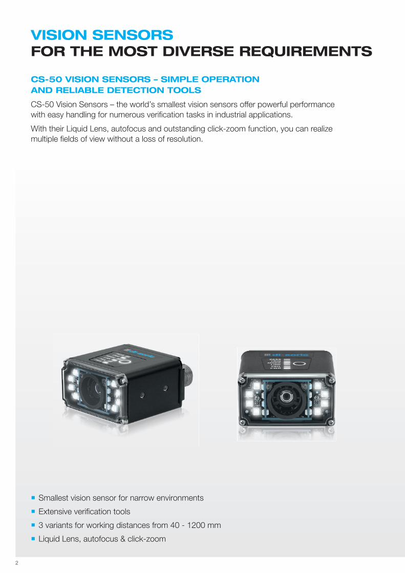
CS-50 VISION SENSORS – SIMPLE OPERATIONAND RELIABLE DETECTION TOOLS
CS-50 Vision Sensors – the world’s smallest vision sensors off er powerful performance with easy handling for numerous verifi cation tasks in industrial applications.
With their Liquid Lens, autofocus and outstanding click-zoom function, you can realize multiple fi elds of view without a loss of resolution.
VISION SENSORS FOR THE MOST DIVERSE REQUIREMENTS
Smallest vision sensor for narrow environments
Extensive verifi cation tools
3 variants for working distances from 40 - 1200 mm
Liquid Lens, autofocus & click-zoom
3
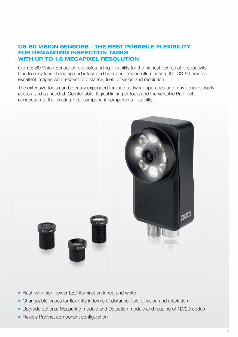
CS-60 VISION SENSORS – THE BEST POSSIBLE FLEXIBILITY FOR DEMANDING INSPECTION TASKS WITH UP TO 1.6 MEGAPIXEL RESOLUTION
Our CS-60 Vision Sensor off ers outstanding fl exibility for the highest degree of productivity. Due to easy lens changing and integrated high-performance illumination, the CS-60 creates excellent images with respect to distance, fi eld of vision and resolution.
The extensive tools can be easily expanded through software upgrades and may be individually customized as needed. Comfortable, logical linking of tools and the versatile Profi net connection to the existing PLC component complete its fl exibility.
Flash with high power LED illumination in red and white
Changeable lenses for fl exibility in terms of distance, fi eld of vision and resolution
Upgrade options: Measuring module and Detection module and reading of 1D/2D codes
Flexible Profi net component confi guration
4
Up to 300% faster performance
The CS-50 off ers a signifi cant increase in speed compared to existing vision sensors. A process speed with up to 2,500 component inspections per minute is possible.
1.4 GB ofmemory
With approximately 1.4 GB of RAM, there is enough memory for practically an unlimited amount of jobs.
The world’s smallest industrial Vision Sensor
The CS-50 is the world’s smallest vision sensor – this also means it can be integrated easily into machines and systems that have limited space.
PLC-compliantdata types
We supply PLC-compliant data formats for a fast, convenient connection to your PLC. This makes it possible to control the parameters in a job via ex-ternal systems using a direct connec-tion to your machine control system.
Click-zoom & Liquid Lens Autofocus
Digitally adjusting both focal lengths and the Liquid Lens Autofocus option when changing a lens does not require the use of hardware and prevents misalignment.
Common interfaceson board
In addition to our PROFINET and RS232 standard protocols, the CS 50 is also able to communicate with your industrial environment via Ethernet/IP and TCP/IP.
Easy to operate
Our new Autovision software can be operated by every sensor user – for everyone who wants to run their applications intuitively with a robust and powerful product.
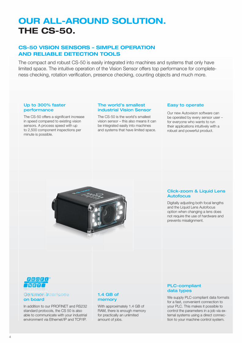
OUR ALL-AROUND SOLUTION. THE CS-50.
CS-50 VISION SENSORS – SIMPLE OPERATIONAND RELIABLE DETECTION TOOLS
The compact and robust CS-50 is easily integrated into machines and systems that only have limited space. The intuitive operation of the Vision Sensor off ers top performance for complete-ness checking, rotation verifi cation, presence checking, counting objects and much more.
R
Common interfacesCommon interfacesCommon interfacesCommon interfacesCommon interfacesCommon interfacesCommon interfacesCommon interfacesCommon interfacesCommon interfacesCommon interfacesCommon interfacesCommon interfacesCommon interfacesCommon interfacesCommon interfacesCommon interfacesCommon interfacesCommon interfacesCommon interfacesCommon interfacesCommon interfacesRCommon interfacesRCommon interfaces
SOFTWARE THE CS-50 IS BASED ON.AUTOVISION.
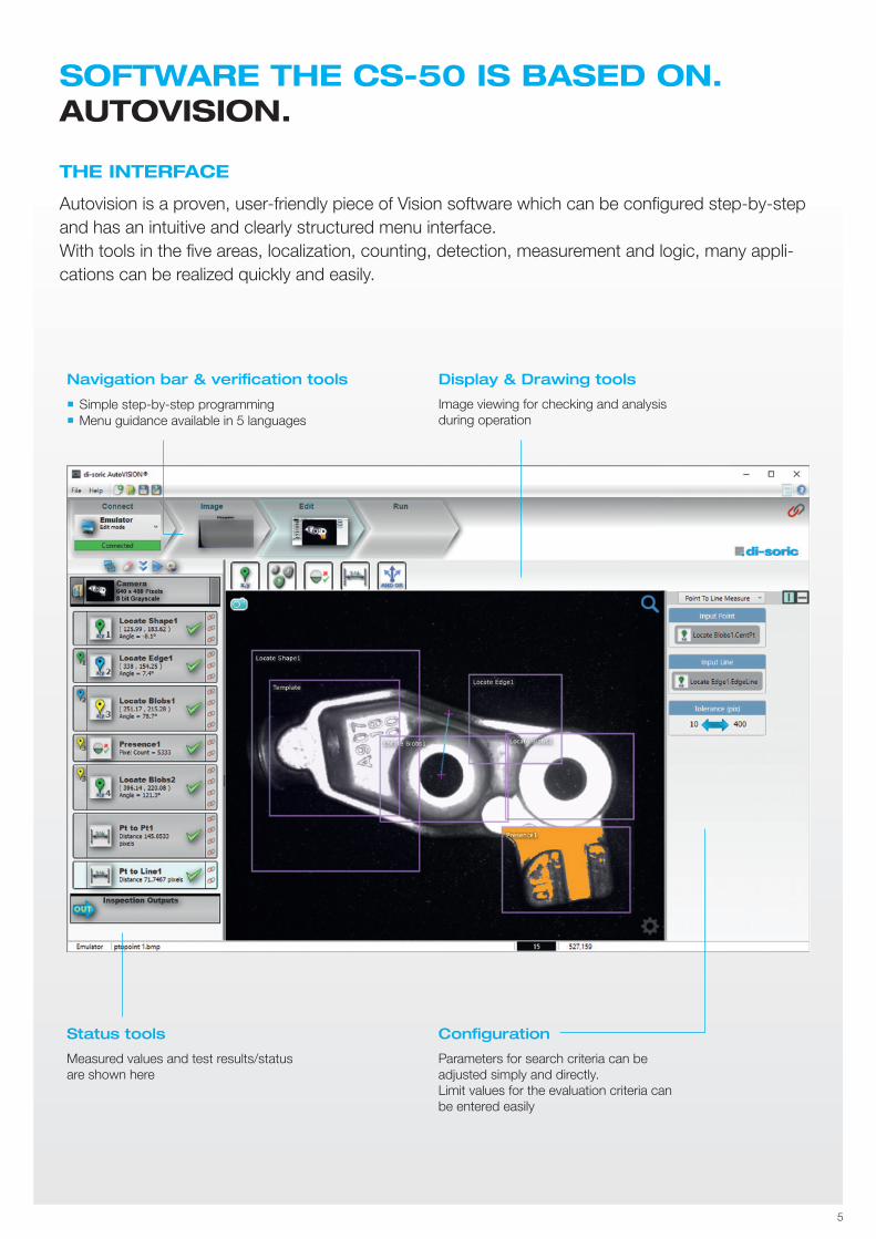
THE INTERFACE
Autovision is a proven, user-friendly piece of Vision software which can be confi gured step-by-step and has an intuitive and clearly structured menu interface.With tools in the fi ve areas, localization, counting, detection, measurement and logic, many appli-cations can be realized quickly and easily.
5
Navigation bar & verification tools
Simple step-by-step programming Menu guidance available in 5 languages
Status tools
Measured values and test results/status are shown here
Configuration
Parameters for search criteria can be adjusted simply and directly.Limit values for the evaluation criteria can be entered easily
Display & Drawing tools
Image viewing for checking and analysis during operation
6
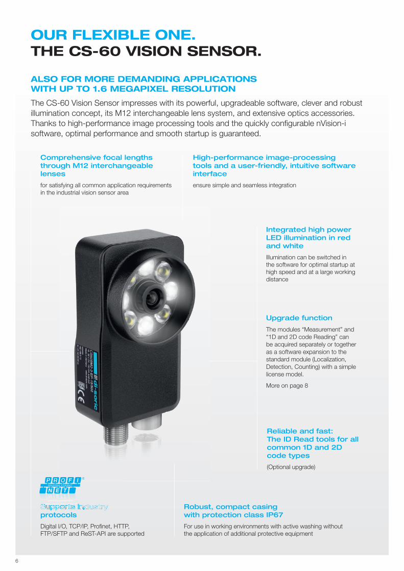
Comprehensive focal lengthsthrough M12 interchangeable lenses
for satisfying all common application requirements in the industrial vision sensor area
Integrated high power LED illumination in red and white
Illumination can be switched in the software for optimal startup at high speed and at a large working distance
Upgrade function
The modules “Measurement” and “1D and 2D code Reading” can be acquired separately or together as a software expansion to the standard module (Localization, Detection, Counting) with a simple license model.
More on page 8
Robust, compact casing with protection class IP67
For use in working environments with active washing without the application of additional protective equipment
Reliable and fast:The ID Read tools for allcommon 1D and 2Dcode types
(Optional upgrade)
Supports industryprotocols
Digital I/O, TCP/IP, Profi net, HTTP,FTP/SFTP and ReST-API are supported
High-performance image-processing tools and a user-friendly, intuitive software interface
ensure simple and seamless integration
OUR FLEXIBLE ONE. THE CS-60 VISION SENSOR.
ALSO FOR MORE DEMANDING APPLICATIONS WITH UP TO 1.6 MEGAPIXEL RESOLUTION
The CS-60 Vision Sensor impresses with its powerful, upgradeable software, clever and robust illumination concept, its M12 interchangeable lens system, and extensive optics accessories. Thanks to high-performance image processing tools and the quickly configurable nVision-i software, optimal performance and smooth startup is guaranteed.
R
Supports industrySupports industrySupports industrySupports industrySupports industrySupports industrySupports industrySupports industrySupports industrySupports industrySupports industrySupports industrySupports industrySupports industrySupports industrySupports industrySupports industrySupports industrySupports industrySupports industrySupports industrySupports industrySupports industryRSupports industry
7
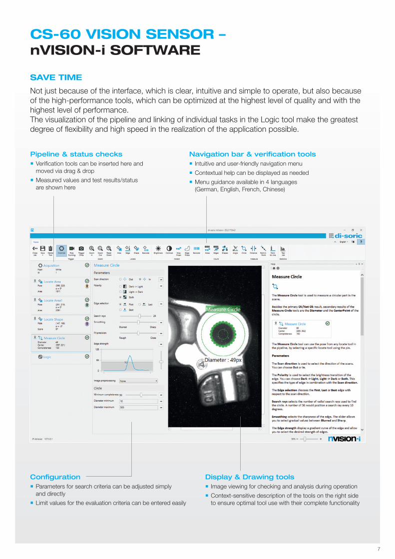
Navigation bar & verification tools Intuitive and user-friendly navigation menu
Contextual help can be displayed as needed
Menu guidance available in 4 languages (German, English, French, Chinese)
Pipeline & status checks Verifi cation tools can be inserted here and
moved via drag & drop
Measured values and test results/status are shown here
Configuration Parameters for search criteria can be adjusted simply
and directly
Limit values for the evaluation criteria can be entered easily
Display & Drawing tools Image viewing for checking and analysis during operation
Context-sensitive description of the tools on the right side to ensure optimal tool use with their complete functionality
SAVE TIME
Not just because of the interface, which is clear, intuitive and simple to operate, but also because of the high-performance tools, which can be optimized at the highest level of quality and with the highest level of performance. The visualization of the pipeline and linking of individual tasks in the Logic tool make the greatest degree of fl exibility and high speed in the realization of the application possible.
CS-60 VISION SENSOR – nVISION-i SOFTWARE
8
CS-60 VISION SENSORnVISION-i SOFTWARE
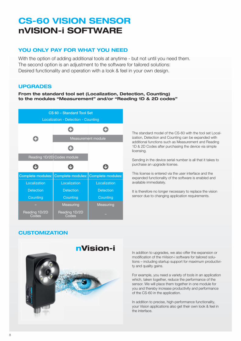
YOU ONLY PAY FOR WHAT YOU NEED
With the option of adding additional tools at anytime - but not until you need them. The second option is an adjustment to the software for tailored solutions:Desired functionality and operation with a look & feel in your own design.
CUSTOMIZATION
The standard model of the CS-60 with the tool set Local-ization, Detection and Counting can be expanded with additional functions such as Measurement and Reading 1D & 2D Codes after purchasing the device via simple licensing.
Sending in the device serial number is all that it takes to purchase an upgrade license.
This license is entered via the user interface and the expanded functionality of the software is enabled and available immediately.
It is therefore no longer necessary to replace the vision sensor due to changing application requirements.
In addition to upgrades, we also offer the expansion or modifi cation of the nVision-i software for tailored solu-tions – including startup support for maximum productivi-ty and quality gains.
For example, you need a variety of tools in an application which, taken together, reduce the performance of the sensor. We will place them together in one module for you and thereby increase productivity and performance of the CS-60 in the application.
In addition to precise, high-performance functionality, your Vision applications also get their own look & feel in the interface.
CS 60 – Standard Tool Set
Localization - Detection - Counting
Reading 1D/2D Codes module
Measurement module
Complete modules:
Localization
Detection
Counting
–
Reading 1D/2D Codes
Complete modules:
Localization
Detection
Counting
Measuring
Reading 1D/2D Codes
Complete modules:
Localization
Detection
Counting
Measuring
–
�
� �
�
� � �
UPGRADESFrom the standard tool set (Localization, Detection, Counting) to the modules “Measurement” and/or “Reading 1D & 2D codes”
nVision-i

THE LOGIC TOOLnVISION-i SOFTWARE
Digital Outputs
Tools
Locate Barcode
Measure Circle
Locate Edge
Locate Edge 1
Detect Area Pixels
Count Edges
Count Areas
Measure Angle
Measure Distance
Digital Outputs PROFINET OutputsResults FTP
Logic Operators
& And
≥1 Or
! Not
�
�
Measure Distance
343 345<= <Distance
+
60 80<= <Angle
+
7 11<= <Score
+
+ -
70 120<= <Angle
+
Measure Angle
Count Areas
& Out 0
+ -
& Out 1
Out 20Value
0Delay (ms)
Locate Edge 1
0Length (ms)
0Delay (ms)
100Length (ms)
1000Delay (ms)
100
1
1
1
1
1
1
1
1
1
1
Length (ms)
Out 30Value
0Delay (ms)
0Length (ms)
9
The graphically oriented Logic tool is based on a function plan (FUP), whereby a clear display is possible, even in more complex functions. This, in turn, ensures that the implementation of the behavior of inputs and outputs is simple and highly transparent.
THE LINKING OF RESULTS WITH OUTPUTS
The free linking of the results of several tools into an overall result directly in the vision sensor provides you with high-performance - without utilizing the PLC.Another advantage is the high degree of fl exibility: the measured values can be addressed at any point on the Profi net fi eldbus.
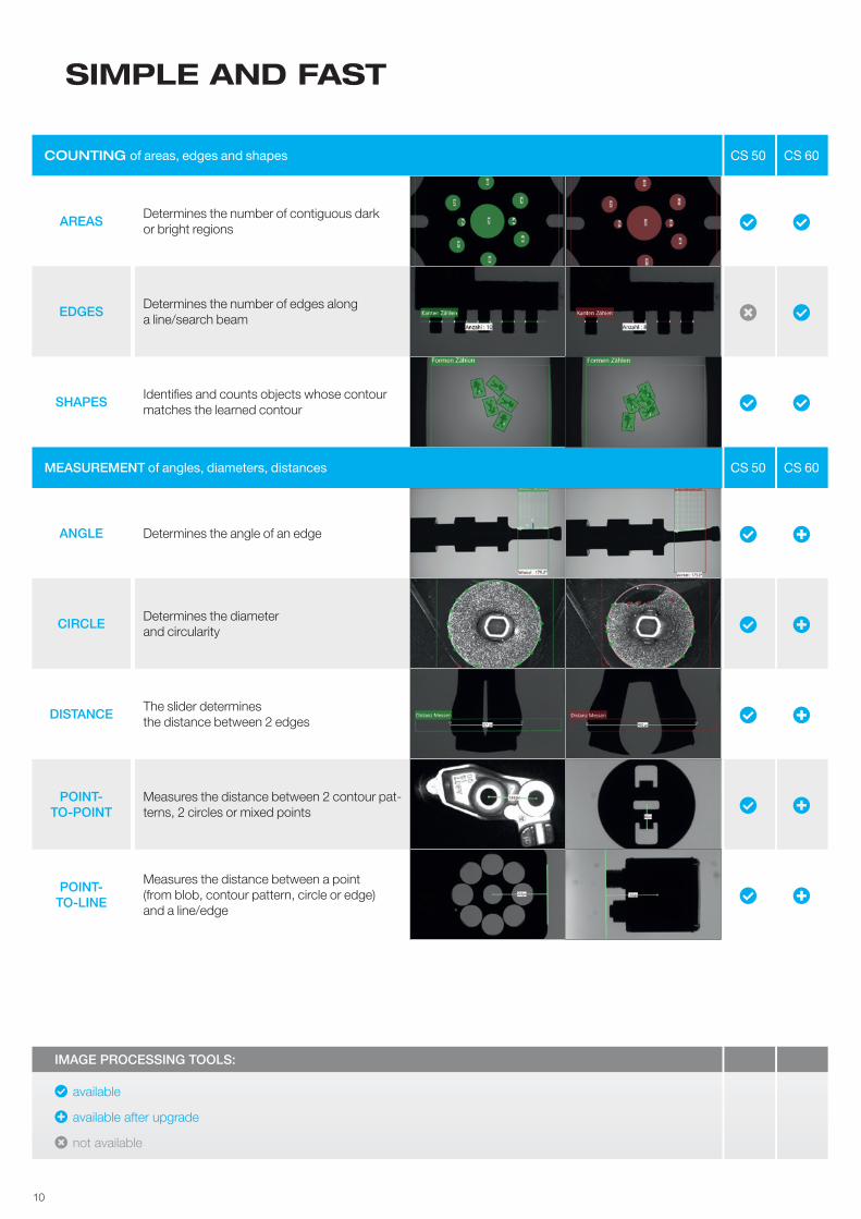
COUNTING of areas, edges and shapes CS 50 CS 60
AREAS Determines the number of contiguous dark or bright regions � �
EDGES Determines the number of edges along a line/search beam � �
SHAPES Identifies and counts objects whose contour matches the learned contour � �
MEASUREMENT of angles, diameters, distances CS 50 CS 60
ANGLE Determines the angle of an edge � �
CIRCLE Determines the diameterand circularity � �
DISTANCE The slider determinesthe distance between 2 edges � �
POINT-TO-POINT
Measures the distance between 2 contour pat-terns, 2 circles or mixed points � �
POINT-TO-LINE
Measures the distance between a point(from blob, contour pattern, circle or edge) and a line/edge
� �
IMAGE PROCESSING TOOLS:
� available
� available after upgrade
� not available
10
SIMPLE AND FAST

LOCALIZATION of areas, edges and shapes CS 50 CS 60
AREAThe tool “Localize area” isused in order to localize apart in a scene using Blob analysis
� �
EDGE Finds an edge within the defined search field and serves as a guide for subsequent tools � �
SHAPECompares learned patterns within the defined working area and also serves as position correction for subsequent tools
� �
DETECTION of the presence/absence of a feature based on pixel values and contrast CS 50 CS 60
BRIGHTNESS Determines average brightnesswithin the defined working area � �
CONTRAST Determines the contrastwithin the defined working area � �
AREAPIXELS
Determines the number of pixels of a partof the scene � �
EDGEPIXELS
Determines the edge texturewithin the defined working area � �
LOCALIZE AND READ 1D and 2D codes CS 60
LOCALIZATION
Finds a code within the defined search field and serves as a guide for subsequent tools. Efficient in checkinglabels
�
READDecodes all codes and can evaluate the content using different criteria (regular expressions)
�
COUNTING Enables multiple recognition of different codes �
11
THE IMAGE PROCESSING TOOLS
12
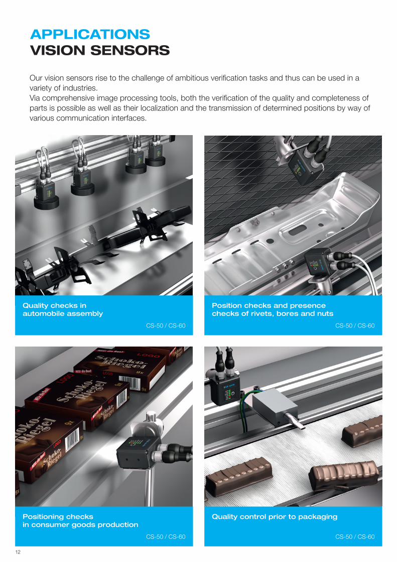
Our vision sensors rise to the challenge of ambitious verifi cation tasks and thus can be used in a variety of industries.Via comprehensive image processing tools, both the verifi cation of the quality and completeness of parts is possible as well as their localization and the transmission of determined positions by way of various communication interfaces.
APPLICATIONSVISION SENSORS
Positioning checksin consumer goods production
Position checks and presencechecks of rivets, bores and nuts
Quality checks inautomobile assembly
Quality control prior to packaging
CS-50 / CS-60
CS-50 / CS-60
CS-50 / CS-60
CS-50 / CS-60
13
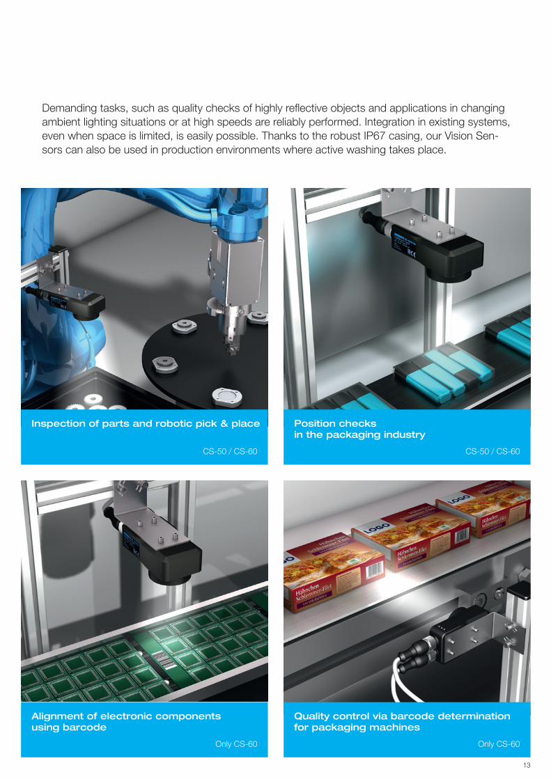
Inspection of parts and robotic pick & place
Alignment of electronic components using barcode
Position checks in the packaging industry
Quality control via barcode determination for packaging machines
Demanding tasks, such as quality checks of highly reflective objects and applications in changing ambient lighting situations or at high speeds are reliably performed. Integration in existing systems, even when space is limited, is easily possible. Thanks to the robust IP67 casing, our Vision Sen-sors can also be used in production environments where active washing takes place.
CS-50 / CS-60
Only CS-60
CS-50 / CS-60
Only CS-60
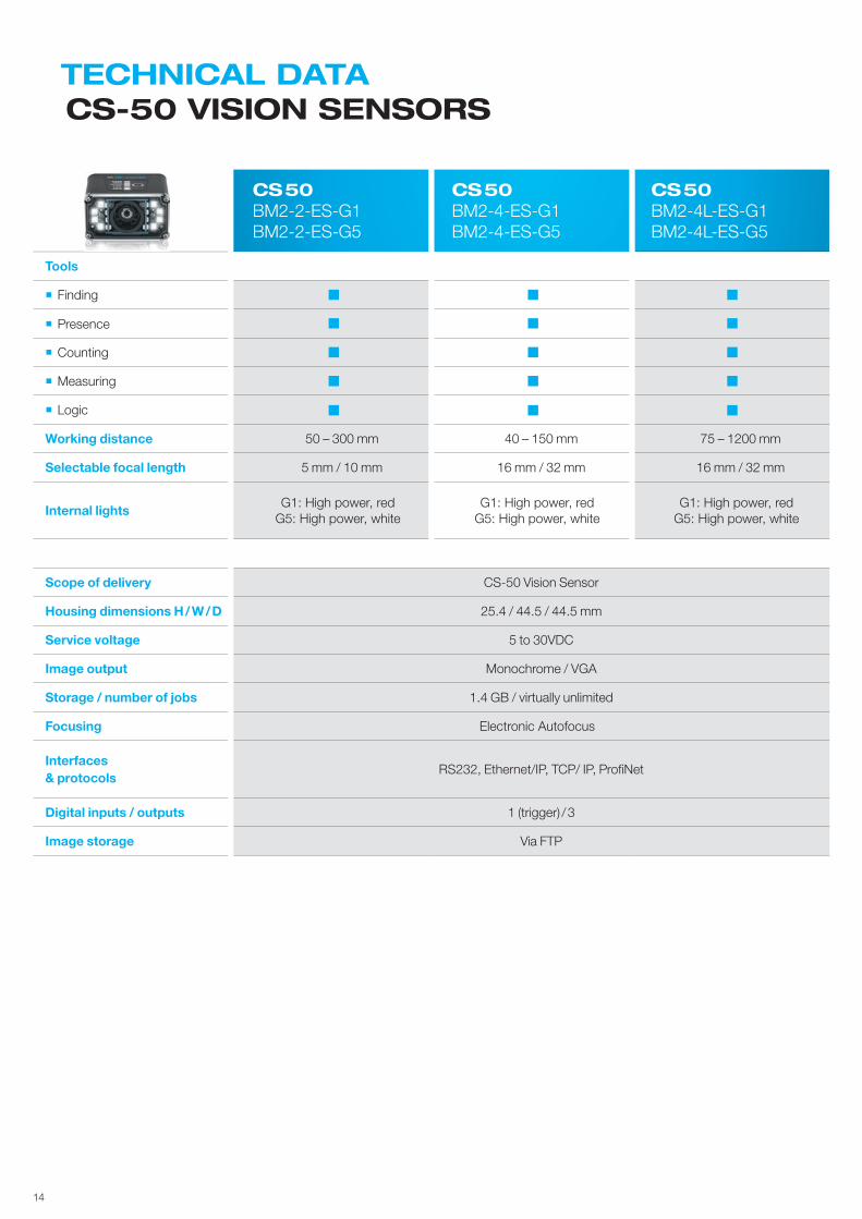
TECHNICAL DATACS-50 VISION SENSORS
14
CS 50 BM2-2-ES-G1BM2-2-ES-G5
CS 50 BM2-4-ES-G1BM2-4-ES-G5
CS 50 BM2-4L-ES-G1BM2-4L-ES-G5
Tools
Finding
Presence
Counting
Measuring
Logic
Working distance 50 – 300 mm 40 – 150 mm 75 – 1200 mm
Selectable focal length 5 mm / 10 mm 16 mm / 32 mm 16 mm / 32 mm
Internal lightsG1: High power, red
G5: High power, whiteG1: High power, red
G5: High power, whiteG1: High power, red
G5: High power, white
Scope of delivery CS-50 Vision Sensor
Housing dimensions H / W / D 25.4 / 44.5 / 44.5 mm
Service voltage 5 to 30VDC
Image output Monochrome / VGA
Storage / number of jobs 1.4 GB / virtually unlimited
Focusing Electronic Autofocus
Interfaces& protocols
RS232, Ethernet/IP, TCP/ IP, ProfiNet
Digital inputs / outputs 1 (trigger) / 3
Image storage Via FTP
15
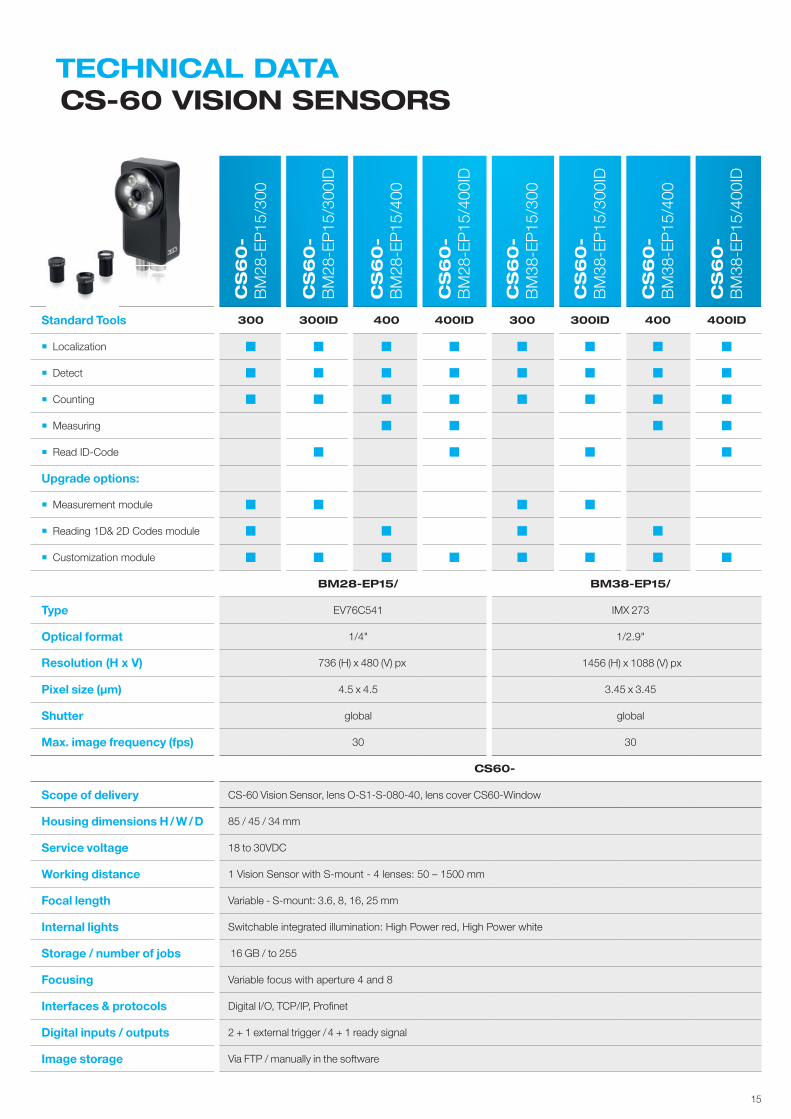
TECHNICAL DATACS-60 VISION SENSORS
CS
60
-B
M28
-EP
15/3
00
CS
60
-B
M28
-EP
15/3
00ID
CS
60
-B
M28
-EP
15/4
00
CS
60
-B
M28
-EP
15/4
00ID
CS
60
-B
M38
-EP
15/3
00
CS
60
-B
M38
-EP
15/3
00ID
CS
60
-B
M38
-EP
15/4
00
CS
60
-B
M38
-EP
15/4
00ID
Standard Tools 300 300ID 400 400ID 300 300ID 400 400ID
Localization
Detect
Counting
Measuring
Read ID-Code
Upgrade options:
Measurement module
Reading 1D& 2D Codes module
Customization module
BM28-EP15/ BM38-EP15/
Type EV76C541 IMX 273
Optical format 1/4" 1/2.9"
Resolution (H x V) 736 (H) x 480 (V) px 1456 (H) x 1088 (V) px
Pixel size (µm) 4.5 x 4.5 3.45 x 3.45
Shutter global global
Max. image frequency (fps) 30 30
CS60-
Scope of delivery CS-60 Vision Sensor, lens O-S1-S-080-40, lens cover CS60-Window
Housing dimensions H / W / D 85 / 45 / 34 mm
Service voltage 18 to 30VDC
Working distance 1 Vision Sensor with S-mount - 4 lenses: 50 – 1500 mm
Focal length Variable - S-mount: 3.6, 8, 16, 25 mm
Internal lights Switchable integrated illumination: High Power red, High Power white
Storage / number of jobs 16 GB / to 255
Focusing Variable focus with aperture 4 and 8
Interfaces & protocols Digital I/O, TCP/IP, Profinet
Digital inputs / outputs 2 + 1 external trigger / 4 + 1 ready signal
Image storage Via FTP / manually in the software
16
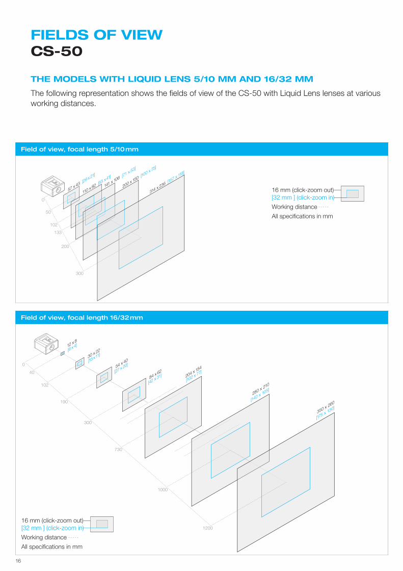
THE MODELS WITH LIQUID LENS 5/10 MM AND 16/32 MM
The following representation shows the fi elds of view of the CS-50 with Liquid Lens lenses at various working distances.
FIELDS OF VIEWCS-50
Field of view, focal length 5/10 mm
Field of view, focal length 16/32 mm
40
0
102
190
300
730
1000
1200
12 x 8
[6 x4]
30 x 22
[15x11]
54 x 40
[27 x20]
84 x 62
[42 x 31] 204 x 154
[102 x 77]
280 x 210
[140 x 105]
350 x 260
[175 x 130]
16 mm (click-zoom out)[32 mm ] (click-zoom in)
Working distance
All specifi cations in mm
16 mm (click-zoom out)[32 mm ] (click-zoom in)
Working distance
All specifi cations in mm
300
200
133
102
50
0
57 x 43 [29 x21]
110 x 82 [5
5 x41]
141 x 106 [7
1 x 53]
200 x 150 [100 x 75]
314 x 236 [157 x 118
]
17
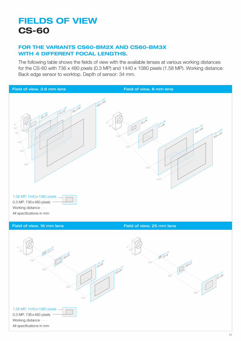
FIELDS OF VIEW CS-60
FOR THE VARIANTS CS60-BM2X AND CS60-BM3X WITH 4 DIFFERENT FOCAL LENGTHS.
The following table shows the fi elds of view with the available lenses at various working distances for the CS-60 with 736 x 480 pixels (0.3 MP) and 1440 x 1080 pixels (1.58 MP). Working distance: Back edge sensor to worktop. Depth of sensor: 34 mm.
Field of view, 3.6 mm lens Field of view, 8 mm lens
Field of view, 16 mm lens Field of view, 25 mm lens
30 x1957 x 43
200 x 130306 x 229
155 x 100243 x 18371 x 46120 x 8
9
515
400
200
100
340
103 x 6779 x 52
150 x 113119 x 8
938 x 2527 x 4317 x 1126 x 20
515
400
200
100
34
0
300
200
140
70
34
0
35 x 2292 x 69
110 x 67202 x 152
271 x 203
165 x 102
262 x 165
410 x 307
1.58 MP, 1440 x 1080 pixels
0.3 MP, 736 x 480 pixels
Working distance
All specifi cations in mm
1.58 MP, 1440 x 1080 pixels
0.3 MP, 736 x 480 pixels
Working distance
All specifi cations in mm
52 x 3894 x 71
28 x 2155 x 41
12 x 825 x 19
500
300
150
340
18
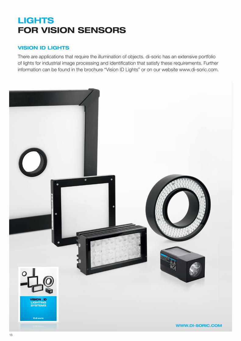
VISION ID LIGHTS
There are applications that require the illumination of objects. di-soric has an extensive portfolio of lights for industrial image processing and identifi cation that satisfy these requirements. Further information can be found in the brochure “Vision ID Lights” or on our website www.di-soric.com.
VISION . IDLIGHTINGSYSTEMS
WWW.DI-SORIC.COM
LIGHTSFOR VISION SENSORS
19
WWW.DI-SORIC.COM
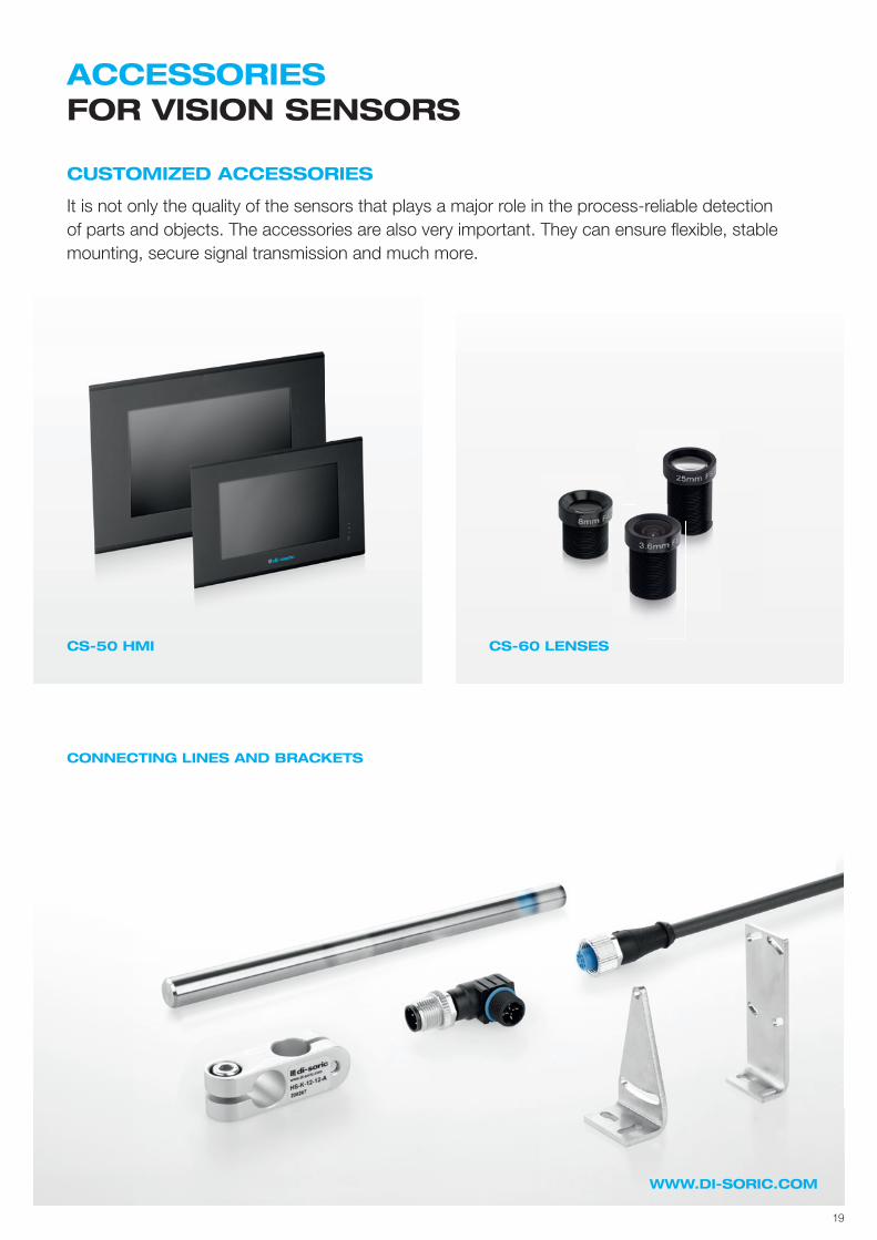
CS-50 HMI CS-60 LENSES
CONNECTING LINES AND BRACKETS
ACCESSORIES FOR VISION SENSORS
CUSTOMIZED ACCESSORIES
It is not only the quality of the sensors that plays a major role in the process-reliable detectionof parts and objects. The accessories are also very important. They can ensure fl exible, stable mounting, secure signal transmission and much more.
© d
i-sor
ic |
All
info
rmat
ion
is s
uppl
ied
with
out g
uara
ntee
. Con
tent
s m
ay c
onta
in m
ista
kes
or p
rint e
rror
s an
d ar
e su
bjec
t to
tech
nica
l cha
nges
. | 1
0002
3-00
0EN
· R
EV02
· B
RO
-VIS
· 20
2010
SOLUTIONS. CLEVER. PRACTICAL.
di-soric headquarters
Germany: di-soric GmbH & Co. KG | Steinbeisstrasse 6 | 73660 UrbachTel +49 71 81 98 79-0 | Fax +49 71 81 98 79-179 | [email protected]
di-soric branch o� ces
Austria: di-soric Austria GmbH & Co. KG | Tel +43 7228 72 366 | [email protected]: di-soric SAS | Tel +33 476 61 65 90 | [email protected] Netherlands: di-soric B. V. | Tel +31 413 33 13 91 | [email protected] Singapore: di-soric Pte. Ltd. | Tel +65 6634 38436 | [email protected]: di-soric SNT AG | Tel +41 44 817 29 22 | [email protected]
Further information available at: www.di-soric.com/international www.di-soric.com