virtualhandout_6423_ac6423-v_compelling drawing views with autocad 2013 2d drawings from autocad 3d...
DESCRIPTION
autocadTRANSCRIPT

Drawing Views with AutoCAD® 2013: 2D Drawings from AutoCAD® 3D Models AC2290-L and AC7046-L (repeat)
Drawing Views with AutoCAD® 2013: 2D Drawings from AutoCAD and Autodesk® Inventor® 3D Models - AC6423-V
J.C. Malitzke – Digital JC CAD
AC2290-L and AC7046-L (repeat) - AC6423-V This intermediate-to-advanced hands-on lab offers AutoCAD® software 3D veterans and 2D users a chance to explore 2D model documentation of 3D models from AutoCAD 2013 and Autodesk® Inventor® 2013 software. Create base views and projected views from 3D solid or surface models. Use the new Viewbase command to generate a base 2D view and the Viewproj command to create projected orthographic views. We will edit the 3D models and update the derived drawing views. We will add dimensions to the drawing views and modify the 3D model to update the dimensions. Are commands such as Flatshot, Solview, Soldraw, and Solproj superseded? We will find out! We will explore the Exportlayout command for exporting a layout containing drawing views to model space. If you used AutoCAD 3D in the past or are new to 3D but have a good 2D background, attend this lab and get ready to be surprised!
LearningObjectivesAt the end of this class, you will be able to:
Use Inventor 3D models for drawing view creation in AutoCAD 2013
Create drawing views from 3D AutoCAD and Inventor models
Edit 3D models and associative drawing views
Edit drawing views
Edit AutoCAD 3D models in Autodesk Inventor Fusion
AbouttheSpeaker J.C. Malitzke is President of Digital JC CAD Services Inc. and is the former department chair of Computer Integrated Technologies and a faculty member at Moraine Valley Community College in the greater Chicago area. He managed and taught for the college’s Autodesk Authorized Training Center. He has been using and teaching Autodesk® products for 27 years. J.C. is co-author to Good-Heart Wilcox Publisher for AutoCAD® and Its Applications Advanced. He is the recipient of several educator awards, including "Professor of the Year," and the Illinois Trustee Association's "Faculty Member of the Year," and a top presenter award winner at Autodesk University. J.C. is a Certified Autodesk Instructor and a Certified Autodesk Evaluator. This is his 18th year presenting at Autodesk University. He holds a BS degree in education and a MS in industrial technology from Illinois State University. Contact J.C. at: [email protected].

Drawing Views with AutoCAD® 2013: 2D Drawings from AutoCAD® 3D Models
2
For AutoCAD 2012 and 2013
Model Documentation
There are multiple techniques available to create drawing views from 3D models in
AutoCAD. Using these techniques, orthographic views and other standard drawing views can be
created in order to produce multiview drawings. The techniques available are discussed in this
paper.
Drawing Views
You can create 2D drawing views from 3D solid or surface models using the VIEWBASE
command. This command allows you to quickly create a multiview drawing layout made up of
orthographic views. Drawing views created with the VIEWBASE command are created in paper
space (layout space). After creating a layout of views, you can dimension them using AutoCAD
dimensioning commands.
Drawing views created with the VIEWBASE command are associative. This means that
they are linked to the model from which they are created and can be updated to reflect changes
to the model geometry. This capability allows you to keep drawing views up-to-date when
design changes are required.
When using the VIEWBASE command, you create a base view of the model and then
have the option to create additional views that are projected from the base view without exiting
the command. You can create both orthographic and isometric views. A base view created with
the VIEWBASE command is defined as a parent view. Views projected from the base view
inherit the properties of the base view, such as the drawing scale and display properties, and
are placed in orthographic alignment with the base view. If the base view is moved, any
projected views are moved with it to maintain the parent-child relationship.
Drawing View and Layout Setup
In order to create views with the VIEWBASE command, you must first activate paper space
(layout space). Activate paper space by picking a layout tab. Then, before creating views, set up
the page layout as required. If a default viewport appears in the layout, delete the viewport.
Then, right-click on the active layout tab and select Page Setup Manager to access the layout
settings. Select the desired paper size, drawing orientation, and other settings. If you have a

Drawing Views with AutoCAD® 2013: 2D Drawings from AutoCAD® 3D Models
3
template drawing already created, you can create a new layout based on the template by right-
clicking on a layout tab and selecting From template….
By default, drawing views created with the VIEWBASE command are generated using
third-angle projection. This is the ANSI standard. The default projection used for drawing views
can be set using the VIEWSTD command. This command and other drawing view commands
are accessed from the Drawing Views panel on the Annotate tab of the ribbon.
Pick the dialog box launcher button at the lower-right corner of the Drawing Views panel
to initiate the VIEWSTD command. This opens the Drafting Standard dialog box.
The options in the Projection type area determine the type of projection used for new
drawing views. By default, the Third angle button is selected. If the First angle button is
selected, views are created using first-angle projection. Select this option to create views in
accordance with ISO standards. The options in the Thread style area determine the type of
thread representation used for views showing threaded features. The thread representation
options are used when creating views from Autodesk Inventor models or imported models
containing threaded features. A full circle thread representation conforms to the ANSI standard.
This is the default option. A partial circle thread representation conforms to the ISO standard.
The options in the Shading/Preview area of the Drafting Standard dialog box determine

Drawing Views with AutoCAD® 2013: 2D Drawings from AutoCAD® 3D Models
4
the type of preview that appears when placing a drawing view. When Shaded is selected in the
Preview type drop-down list, a shaded view appears. This is the default option. This option
provides a preview image of the view orientation before the view is placed. When the Bounding
box option is selected, a preview box representing the extents of the view appears. However,
no preview image is displayed. The Shaded view quality option is set to 100 dpi by default. A
higher setting will provide better resolution quality when a shaded preview is displayed.
However, for all practical purposes, a setting of 150 dpi or higher does not produce a dramatic
difference in resolution quality.
Creating Drawing Views
After setting up a layout and making the appropriate drawing view settings, you are ready to
place the base view. As previously discussed, drawing views can be created from a 3D solid or
surface model. Drawing views created in the layout are generated from the model you have
created in model space. If no model exists in the drawing and you initiate the VIEWBASE
command. You can select a model created in AutoCAD or a model created in Autodesk
Inventor. You can select Base from the Layout tab, Create View panel.

Drawing Views with AutoCAD® 2013: 2D Drawings from AutoCAD® 3D Models
5
When you select the VIEWBASE command, a preview representing a scaled orthographic
view of the model appears. This is the base view of the model. You can then specify the
location of the base view or select an option.
To select an option, use dynamic input or make a selection from the Drawing View Creation
contextual ribbon tab. The Orientation option can be used to select a different view from the
default base view. The Orientation options correspond to AutoCAD’s six orthographic and four
isometric preset views. These views are based on the WCS.
By default, the front view is used as the base view by AutoCAD. Depending on the construction
of your model, you may want to use a different view, such as the top view, to serve as the base
view. This view will establish the front view on the orthographic drawing. In most cases, the front
orthographic view on the drawing describes the most critical contour of the model. You will
typically use the front or top view of the 3D model for the front orthographic view on the drawing.
Creating a base view creates an AutoCAD drawing view object. A drawing view has a view
border, a base grip, and properties that can be edited, such as the view scale. However, the
content of the drawing view cannot be edited. When a base view is created, new layers are
created by AutoCAD for the drawing view geometry. Object lines (visible lines) in the view are
placed on a newly created layer named Visible. Hidden lines in the view are placed on a newly
created layer named Hidden. The drawing view object is placed on a newly created layer named
Base. Additional layers may be created by AutoCAD, depending on the type of model, display
style used, and edges displayed in the view. However, the layers are only created to organize
the drawing view geometry. The layer properties can be modified to change the appearance of
the drawing view geometry, but the geometry cannot be otherwise modified.
The Type option of the VIEWBASE command is available before picking the initial location
of the base view. This option is used to specify whether projected views are placed after placing
the base view. By default, this option is set to Base and Projected. With this option, you can
place additional, projected views while the VIEWBASE command is still active. Projected views
that you place are projected from the base view and oriented in the proper orthographic
alignment. As previously discussed, projected views have a parent-child relationship with the
base view. The base view is the parent view and any projected views are child views. If the
base view is moved, for example, the projected view is moved with it. Projected views are not
created with the VIEWBASE command when the Type option is set to Base only. If you place a

Drawing Views with AutoCAD® 2013: 2D Drawings from AutoCAD® 3D Models
6
base view in this manner and later decide to create projected views from the base view, you can
use the VIEWPROJ command. The VIEWPROJ command allows you to place projected views
from any selected view.
After you pick the location for the base view, you can press [Enter] to place projected views
(if the Type option is set to Base and Projected). Drag the cursor away from the base view and
then pick to locate the projected view. The direction in which you move the cursor determines
the orientation of the projected view. You can continue placing projected views, or you can
press [Enter] to end the command. To end the command without placing projected views, press
[Enter] twice.
When you place the base view, you can select an option to change the default style, scale,
or visibility of the base view before placing projected views. Projected views inherit the
properties of the base view. The Style option is used to set the display style of the base view.
The four options available are Wireframe, Wireframe with Hidden Edges, Shaded, and
Shaded with Hidden Edges. These options can be selected using dynamic input or the
Drawing View Creation contextual ribbon tab.
The Scale option is used to set the scale of the base view. You can select a scale from the
drop-down list in the Appearance panel in the Drawing View Creation contextual ribbon tab.
You can also specify the scale by typing a value.
The Move option allows you to move the base view after picking the initial location on
screen. When you select the Move option, the view is reattached to the cursor so that you can
move it to another location. After you pick a new location, the VIEWBASE options are again
made available.
The Visibility option allows you to control the display of drawing geometry in the view. The
Interference edges option controls whether both object and hidden lines are displayed for
interference edges. By default, this option is set to No. The Tangent edges option controls
whether tangential edges are displayed to show the intersection of surfaces. By default, this
option is set to No. If this option is set to Yes, you can specify whether tangent edges are
shortened to distinguish them from object lines that overlap. The Bend extents option is only
available when working with a model that includes a view with sheet metal bends. The Thread
features option controls thread displays on models with screw thread features. The
Presentation trails option is used to control the display of trails in views created from
presentation files.

Drawing Views with AutoCAD® 2013: 2D Drawings from AutoCAD® 3D Models
7
Additional drawing view options can be accessed by selecting View Options in the
Appearance panel of the Drawing View Creation contextual ribbon tab. This option is not
available on the command line. Selecting View Options opens the View Options dialog box.
The options in the View Justification drop-down list determine the justification of the view. The
justification refers to how the view is “anchored.” When changes are made to the model, such
as a change in size, the view updates based on the justification setting. If the justification is set
to Fixed, geometry in the view unaffected by the edit does not change from the original location.
If the justification is set to Center, the geometry updates about the center point of the view.
A multiview drawing layout is created by placing three projected views after placing the
base view. The projected views include two orthographic views and an isometric view. Notice
that wireframe styles are used for the orthographic views and a shaded style is used for the
isometric view. Drawing views can be edited after placing them to change properties as needed.
In addition, as previously discussed, drawing views can be updated when changes are made to
the model.
NOTE:
The Representation option of the VIEWBASE command is used to create a view based on
a model representation and is only available when working with models created in Autodesk
Inventor.
Updating Drawing Views
Drawing views maintain an associative relationship with the model from which they are
created. However, it is important to note that this associative relationship is controlled by the
model, not the drawing view. When making design changes, you make changes to the model
geometry, not the drawing view.
During the design process, it is often necessary to make modifications. If you have created
drawing views from a model, and then make modifications to the model, the derived base view
and any views projected from the base view will require updating. When this occurs, drawing
views are considered out-of-date. AutoCAD does not automatically update the views when the
model is modified. However, you can quickly update drawing views when needed.

Drawing Views with AutoCAD® 2013: 2D Drawings from AutoCAD® 3D Models
8
VIEWUPDATE
When you make changes to a model in model space and then switch to a layout with
drawing views, red markers appear to indicate that the views are out-of-date. In addition, a
balloon notification appears on the status bar. You can pick the link in the balloon notification to
update the views, or you can use one of the view update commands in the Drawing Views
panel on the Annotate tab of the ribbon. In the example, all of the views are updated at once
based on a change to the original part.
Example Change the cylinders diameters to a larger diameter and then use
VIEWUPDATE to update the drawing views. What happens?
This is the preferred method for updating views. However, you can also update views
individually by selecting Update View from the drop-down menu in the Drawing Views panel
on the Annotate tab of the ribbon. This requires you to select each view to update individually.
Selecting Update View is the same as using the VIEWUPDATE command. When using this
command, you are prompted to select each view to update. You and also set the views to Auto
Update. Select Auto Update from the Layout tab, Update Panel.

Drawing Views with AutoCAD® 2013: 2D Drawings from AutoCAD® 3D Models
9
NOTE:
Drawing views are different from viewports. You cannot pick inside of the view and edit or
modify the drawing geometry by any standard AutoCAD editing technique. Drawing views can
only be updated by changing the 3D model geometry.
PROFESSIONAL TIP:
In order to modify solid primitive subobjects in a composite solid model, the solid history
must be recorded.
1. Open the drawing Flange_Base.dwg
2. Select the ANSI B layout.
3. Create a 4 view drawing as shown below.
4. Turn Auto Update off.
5. Set the orientation to Top and place the top view.
6. Project the front, right side and isometric views.
7. Double click on the isometirc view and change the visibility to Shaded with visible lines.
8. In the 3D model, use sub-object editing to change the diameter of the center bore to 2.00 (radius

Drawing Views with AutoCAD® 2013: 2D Drawings from AutoCAD® 3D Models
10
1.00). Make changes in the properties palette.
9. Change the diameter of the filleted boss hole to .600 (radius 3.00).
10. Update your drawing.
11. Save the drawing as Flange_Base_Done.dwg
Drawing views can be edited after being created. Like other AutoCAD objects, drawing
views can be moved or rotated. In addition, certain properties of drawing views, such as the
display style and scale, can be modified.
VIEWEDIT
The VIEWEDIT command can be used to edit the properties of a drawing view. You can
quickly initiate this command by double-clicking on a view. The Drawing View Editor contextual
ribbon tab appears. The editing options are similar to the options available when you create a
base view.
Creating an Assembly drawing and adding parts to the assembly
1. Open the drawing Fixture Assembly.dwg
2. Create the base view (front) and the top, right side and isometric views.
3. Scale the isometric view to a larger scale.
4. Use the INSERT command to insert the plug at X=20, Y=8 and Z=7, centered on the top hole as
shown. Update the drawing.

Drawing Views with AutoCAD® 2013: 2D Drawings from AutoCAD® 3D Models
11
5. Move other parts as needed. Remember to update the drawing!
Creating Drawing Views from Inventor part files (IPT’s)
Drawing views can be created from sources other than AutoCAD 3D models. You can
create views from Autodesk Inventor® part (IPT), assembly (IAM), or presentation (IPN) files.
You can also create drawing views from models imported with the IMPORT command. Drawing
views can also be created from an assembly or subassembly to create an assembly drawing.
CLOSE all AutoCAD drawings.
OPEN: Blank Drawing.dwg.
OPEN: Coupler3.ipt in Autodesk Inventor.
1. In AutoCAD, turn off Auto Update.
2. Create the 4 view drawing of the Coupler3.ipt file starting with a Base view From Inventor inside
AutoCAD.
3. Change the LTSCALE as needed.
4. Save the drawing as Coupler3.dwg.
5. Close the drawing.

Drawing Views with AutoCAD® 2013: 2D Drawings from AutoCAD® 3D Models
12
6. In Autodesk Inventor, edit Holes 6 and 7 (the two larger holes and the one smaller hole) in
Autodesk Inventor to a .03 diameter.
7. Save the Coupler3.ipt file.
8. Open the AutoCAD drawing Coupler3.dwg. Update the views.
Dimensioning Drawing Views
1. Open the drawing Flange_Base_Done.dwg or Flange_Base_Finished.dwg.
2. Type DIMASSOC and set the variable to 2.
3. Add the three dimensions as shown on the ANSI B layout.
4. Edit the .4000 diameter hole to 3.000.
5. Edit the .600 diameter hole to .500.
6. Edit the 1.00 height to .750.
7. Update the drawing. What happens? Use DIMREASSOSSOCIATE.

Drawing Views with AutoCAD® 2013: 2D Drawings from AutoCAD® 3D Models
13
8. Do not save the drawing.
After placing drawing views on a paper space layout, you can dimension each view as
needed. When dimensioning drawing views, make sure that the DIMASSOC system variable is
set to 2 so that associative dimensions are created. Associative dimensions are associated to
the dimensions of the model and update when the physical model changes.
If you dimension drawing views with associative dimensions, make changes to the model,
and then update the views, the dimensions may become disassociated. In this case, AutoCAD
will ask if you want to reassociate the dimensions. See Figure 15-14. If you select Try to
reassociate annotations, AutoCAD will attempt to reassociate the dimensions automatically. If
AutoCAD is unable to reassociate all dimensions, you will be prompted to use the
DIMREASSOCIATE command. Selecting Run DIMREASSOCIATE will allow you to pick points
in the view to reassociate the dimensions. For more information on the DIMREASSOCIATE
command and associative dimensioning, refer to AutoCAD and Its Applications—Basics.
Using the EXPORTLAYOUT Command
You can use the EXPORTLAYOUT command to export a layout containing drawing views
into a new drawing (DWG) file. However, this technique will break the associativity between the
3D model and the drawing views. The advantage to using this technique is that the drawing
geometry can be edited in the same way as any other AutoCAD 2D geometry in model space.
The disadvantage is that the 2D geometry has lost any associativity back to the 3D model.

Drawing Views with AutoCAD® 2013: 2D Drawings from AutoCAD® 3D Models
14
When using the EXPORTLAYOUT command, you save the exported layout as a DWG file. The
drawing views become blocks in the new drawing file.
1. Open the drawing flange.dwg.
2. Type EXPORTLAYOUT.
3. Save the default name to create the new DWG. Open the new DWG when prompted.
4. What are the 4 new AutoCAD objects? Make modifications to the drawing as needed.
Dimension in Model Space as needed.
5. Do not save the drawing.

Drawing Views with AutoCAD® 2013: 2D Drawings from AutoCAD® 3D Models
15
New for AutoCAD 2013
Section Views
A section view shows the internal features of an object along a section line (cutting plane).
A section view is projected from an existing view, such as an orthographic top view. The existing
view serves as a parent view. To create a section view, you pick points on the parent view to
define the section line (cutting-plane line). You can also select an object, such as a line or
polyline, to define the section line. Section views are created using the VIEWSECTION
command. This command can be used to create full, half, offset, or aligned sections from an
AutoCAD 3D model or an Autodesk Inventor file.
Section views created with the VIEWSECTION command are created in the same paper
space layout as other drawing views. Section views are associative. A section view is linked to
the parent view that creates the section view. As with other types of drawing views, section
views are updated automatically when model changes are made if the VIEWUPDATEAUTO
system variable is set to 1.
By default, a section identifier is placed with the section line and a section view label is
placed with the section view when you create the view. The section identifier is automatically
incremented when you place additional section views. The text objects used for the section
identifier and section view label contain fields that update according to changes made to the
section view. The appearance of elements in the section identifier and section view label is
controlled by the section view style. A section view style defines settings such as the text style
and height, direction arrow size and length, and hatch pattern used for sectioning. A section
view style is similar to a dimension style and includes similar controls.
VIEWSECTIONSTYLE
The VIEWSECTIONSTYLE command is used to create and modify section view styles.
This command accesses the Section View Style Manager dialog box.

Drawing Views with AutoCAD® 2013: 2D Drawings from AutoCAD® 3D Models
16
Picking the New… button allows you to create a new section view style. Picking the
Modify button opens the Modify Section View Style dialog box for the selected style. The tabs
in the New Section View Style dialog box or the Modify Section View Style dialog box are
used to make settings for the section identifier, cutting-plane line, section view label, and section
line hatching. You can apply, modify, and delete section view styles during the design process
or after a section view is created. Develop standards for section views similar to the standards
you develop for text and dimensions. Section view styles should follow company or industry
standards.
Once created, section views can be edited by editing the section line and editing properties
of the section view, such as the hatch pattern used for the section. The following sections
discuss techniques for creating and editing section views.
NOTE
New layers are created by AutoCAD for the drawing view geometry when a section view is
created. The section line and section view label are placed on a layer named MD_Annotation.
The section pattern is placed on a layer named MD_Hatching.
Full Section
VIEWSECTION
A full section “cuts” the parent view of the object in half. It is created by making a cut
completely through the object.
To create a full section, select the VIEWSECTION command and then select the parent
view. The parent view can be a base view or a projected view. Next, select the Type option and
then select the Full option. This option can be accessed directly from the ribbon by selecting the

Drawing Views with AutoCAD® 2013: 2D Drawings from AutoCAD® 3D Models
17
Full option from the Section drop-down list in the Create View panel of the Layout tab. Once
you select the parent view, you are prompted to specify the start point of the section line. Use
object snaps and object snap tracking to assist in specifying the start point. Then, drag the
cursor and pick the end point of the section line. The section line is created and a preview of the
section view is aligned perpendicular to the section line. The dragging direction from the section
line determines the viewing direction. Move the section view to the desired location and pick. To
break the alignment between views, press the [Shift] key once. To restore the alignment, press
the [Shift] key again. When you pick a location for the view, you can select an option or press
[Enter] to exit the command. You can adjust options using the Section View Creation
contextual ribbon tab. You can also use dynamic input or the command line.
The Hidden lines, Scale, and Visibility options allow you to adjust the display style, scale,
and edge visibility. These are the same options available with other types of drawing views. The
Projection option is used to set the type of projection when creating a section line with multiple
segments. The Orthogonal option projects the view orthogonally and creates a true projection.
This is typically preferred, depending on the orientation of the section line. The Normal option
projects the view normal to the cutting plane and is preferred for certain section line orientations,
such as an angled line used to create an aligned section in accordance with conventional
drafting practices. The Depth option is used to control the visibility of objects “behind” the
section line. When you select this option, a depth line appears at the section line. Hovering over
this line and dragging allows you to set the depth of the section view. Objects that are behind
the depth line will not be visible in the section view. Selecting the default Full option includes all
objects within the section view. Selecting the Slice option removes all objects behind the
section line, creating a thin representation section view. The Slice option may be practical for
special section view documentations.
The Annotation option allows you to enter the text used for the section identifier and
specify whether a view label is shown. As previously discussed, the section identifier is
automatically incremented when creating additional section views. The Hatch option is used to
specify whether a hatch pattern is used for the section view. The Move option allows you to
adjust the location of the view after selecting the initial position. When using this option, you can
press the [Shift] key to break the alignment between views.
Section views can be used to create projected views. An isometric view has been created
from a full section view to show an isometric representation of the “cut.” By default, an isometric

Drawing Views with AutoCAD® 2013: 2D Drawings from AutoCAD® 3D Models
18
view projected from a section view shows the section and inherits the display properties of the
parent view.
Exercise 1 Full Section
1. Open the drawing Flanged_Coupler_FullSection.dwg. 2. Select the ANSI A layout. 3. On the ribbon, select the Layout tab. 4. From the Create View panel, create a base view From Model Space as the Top view. Set
orientation to Top with Hidden Lines set to visible and hidden lines. 5. Create a Full section as the front view. 6. Add a projected isometric view projected from the front view. 7. Edit the isometric view to shaded with visible lines. Double click on the isometric view and set
Hidden Lines to Shaded with visible lines. 8. Reset the Scale of all views to 1:4. 9. Double click on the hatch pattern in the front and isometric views Set the hatch scale to .75. 10. The final drawing is shown below. 11. Save the drawing as Full Section.dwg
Exercise 2 Full Section
An example of using the Depth option to adjust a half section is shown below. The full
section is created with the section line drawn through the middle of the object. The Depth option
is selected to move the depth line to the back end of the hole feature. In this case, adjusting the
depth of the section line helps clarify the interior detail of the part.
1. Open the drawing SupportBrace.dwg.

Drawing Views with AutoCAD® 2013: 2D Drawings from AutoCAD® 3D Models
19
2. Select the B-Size layout. 3. Create a base view as the top view. 4. Create the front view as a Full section view from the top view. Click on the left circle that
represents the foot in the top view to use the start point of the section line (cutting plane line). Hint: turn on tracking and object snap tracking to track for objects in the base or parent view for starting the first section lines endpoint.
5. Click across the part tracking from the left center circle past the right circle. Place the section line as shown.
6. View the preview of the section by moving the section view in-place as shown. The preview will be aligned perpendicular similar to placing drawing views.
7. Set the Depth option so the depth line distance turns off the visibility of objects behind the depth line.
8. Select a location for the section view and the O.K. 9. Create a project isometric view from the Top view. 10. Scale the isometric view 1:2. 11. Save the drawing as SupportBrace_Finished.dwg
Half Section
VIEWSECTION
A half section is half of a full section. It represents one-quarter of the object cut away. Half
sections are most typically used for symmetrical objects. The half of the object that is not
sectioned is usually shown as a solid object with no hidden lines.
To create a half section, select the VIEWSECTION command, select the parent view, and
access the Half option. The option is accessed directly from the ribbon by selecting the Half
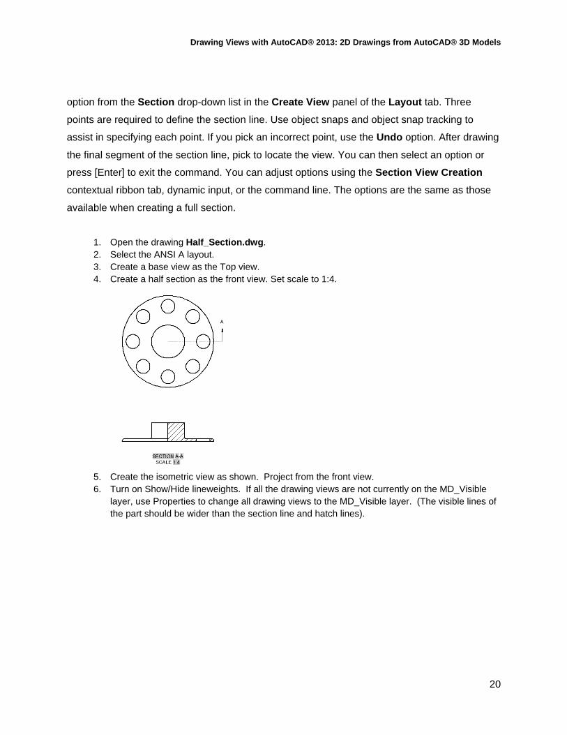
Drawing Views with AutoCAD® 2013: 2D Drawings from AutoCAD® 3D Models
20
option from the Section drop-down list in the Create View panel of the Layout tab. Three
points are required to define the section line. Use object snaps and object snap tracking to
assist in specifying each point. If you pick an incorrect point, use the Undo option. After drawing
the final segment of the section line, pick to locate the view. You can then select an option or
press [Enter] to exit the command. You can adjust options using the Section View Creation
contextual ribbon tab, dynamic input, or the command line. The options are the same as those
available when creating a full section.
1. Open the drawing Half_Section.dwg. 2. Select the ANSI A layout. 3. Create a base view as the Top view. 4. Create a half section as the front view. Set scale to 1:4.
5. Create the isometric view as shown. Project from the front view. 6. Turn on Show/Hide lineweights. If all the drawing views are not currently on the MD_Visible
layer, use Properties to change all drawing views to the MD_Visible layer. (The visible lines of the part should be wider than the section line and hatch lines).

Drawing Views with AutoCAD® 2013: 2D Drawings from AutoCAD® 3D Models
21
7. Save the drawing as Half_Section-Finished.dwg.
Offset Section
VIEWSECTION
An offset section shifts (offsets) the section line to pass through certain features of a part or
assembly for better clarification of detail. Typically, the section line consists of several segments
drawn through features such as holes and bosses.
To create an offset section, select the VIEWSECTION command, select the parent view,
and access the Offset option. The option is accessed directly from the ribbon by selecting the
Offset option from the Section drop-down list in the Create View panel of the Layout tab.
Then, pick the points to define the section line. Select as many points as needed to define the
section. Use object snaps and object snap tracking as needed. If you pick an incorrect point,
use the Undo option. After drawing the final segment of the section line, select the Done option.
Then, pick to locate the view. You can then select an option or press [Enter] to exit the
command. The options are the same as those available when creating a full section.
1. Open the drawing Offset_Base_Section.dwg. 2. Select the ANSI B Layout. 3. The top view has been created for you. 4. Create an offset section as the front view. Scale is set to 1:8.
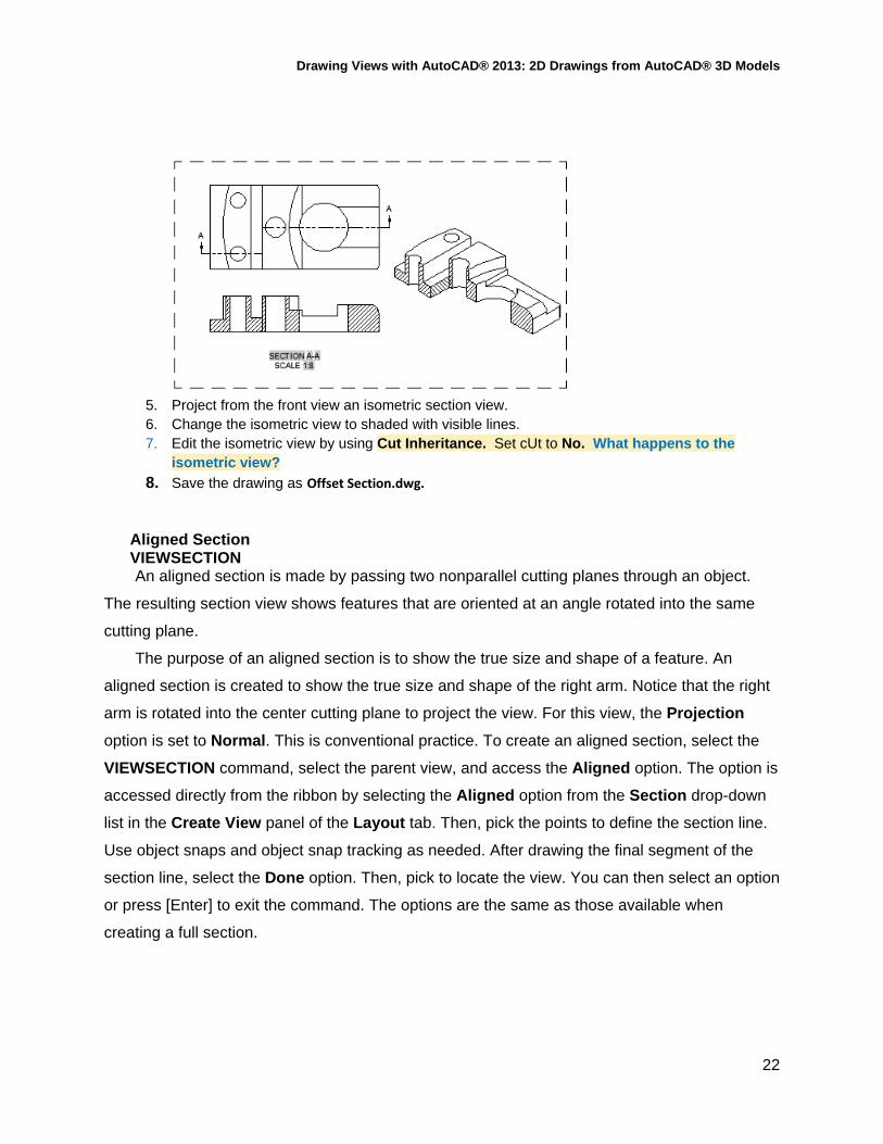
Drawing Views with AutoCAD® 2013: 2D Drawings from AutoCAD® 3D Models
22
5. Project from the front view an isometric section view. 6. Change the isometric view to shaded with visible lines. 7. Edit the isometric view by using Cut Inheritance. Set cUt to No. What happens to the
isometric view?
8. Save the drawing as Offset Section.dwg.
Aligned Section VIEWSECTION An aligned section is made by passing two nonparallel cutting planes through an object.
The resulting section view shows features that are oriented at an angle rotated into the same
cutting plane.
The purpose of an aligned section is to show the true size and shape of a feature. An
aligned section is created to show the true size and shape of the right arm. Notice that the right
arm is rotated into the center cutting plane to project the view. For this view, the Projection
option is set to Normal. This is conventional practice. To create an aligned section, select the
VIEWSECTION command, select the parent view, and access the Aligned option. The option is
accessed directly from the ribbon by selecting the Aligned option from the Section drop-down
list in the Create View panel of the Layout tab. Then, pick the points to define the section line.
Use object snaps and object snap tracking as needed. After drawing the final segment of the
section line, select the Done option. Then, pick to locate the view. You can then select an option
or press [Enter] to exit the command. The options are the same as those available when
creating a full section.

Drawing Views with AutoCAD® 2013: 2D Drawings from AutoCAD® 3D Models
23
1. Open the drawing Aligned-Section.dwg. 2. Select the ANSI A Layout. 3. The top view has been created for you. 4. Create an aligned section as the front view.
5. Create a new view section style and apply with the text height set to .125. 6. Double click on the front view to set the projection from orthogonal to normal. 7. Project the top view as an isometric view. 8. Edit the isometric view by turn off tangent edges. 9. Edit the isometric view by changes the appearance to shaded with visible lines.

Drawing Views with AutoCAD® 2013: 2D Drawings from AutoCAD® 3D Models
24
10. Save the drawing as Aligned.dwg.
Creating a Section View from an Object
You can select an object in the paper space layout to use as the section line when creating
a section view. This is a useful method when it is difficult to locate points using the
VIEWSECTION command. To use an object as the section line, select the VIEWSECTION
command, select the parent view, and access the Object option. The option is accessed directly
from the ribbon by selecting the From Object option from the Section drop-down list in the
Create View panel of the Layout tab. Then, select the object and press [Enter]. Pick a point to
locate the view. The object you select determines the type of section created. A polyline is
drawn in the desired location prior to accessing the From Object option of the VIEWSECTION
command. This is an alternate way to create the section view and may be easier than picking
points. When using the Object option, the selected object is automatically deleted after creating
the section view.
Constraining Section Lines When picking points to define a section line, you have the option to apply constraints to
control the location of the line. If Infer Constraints is activated, constraints are automatically
applied when you pick points. The Infer Constraints button on the status bar controls whether
constraints are inferred when drawing new objects. Inferring constraints provides a way to
constrain the geometry of the section line to the geometry in the drawing view. This is similar to
applying constraints automatically when drawing objects in model space.
Excluding Components from Sectioning
Certain features in section views, such as fasteners, are not shown sectioned. For example,

Drawing Views with AutoCAD® 2013: 2D Drawings from AutoCAD® 3D Models
25
components such as screws, pins, and thin-walled objects in an assembly are shown without
section lines. This practice conforms with drafting standards. When creating a section view from
a parent view that includes items such as fasteners and shafts, you can use the
VIEWCOMPONENT command to control how sectioning is applied.
Editing Section Views
The VIEWEDIT command, can be used to edit the properties of a section view. You can
quickly initiate this command by double-clicking on a section view. This displays the Section
View Editor contextual ribbon tab. Many of the same options used when creating a section view
are available in this tab. Additional options may be available depending on the type of view
selected.
The Cut Inheritance option is available when a view created from a section view inherits
the section cut. An example of this is an isometric view projected from a section view. By
default, the isometric view shows the section cut with the sectioned portion hatched. To remove
the section cut from the isometric view, expand the Cut Inheritance drop-down list in the
Section View Editor contextual ribbon tab and uncheck the Section cut option. This resets the
view to an isometric view without sectioning.
Detail Views

Drawing Views with AutoCAD® 2013: 2D Drawings from AutoCAD® 3D Models
26
A detail view shows a selected portion of a view to clarify model details. A detail view is
projected from a parent view and is typically shown at a larger scale. As with other types of
projected views, the detail view is linked to the parent view. If you change the scale of the
parent view, the detail view scales accordingly.
Detail views are created using the VIEWDETAIL command. A detail view is created by
drawing a circular or rectangular boundary to define the extents of the view. You can create
detail views from an AutoCAD 3D model or an Autodesk Inventor file.
Detail views are associative. As with other types of drawing views, detail views are updated
automatically when model changes are made if the VIEWUPDATEAUTO system variable is set
to 1.
VIEWDETAILSTYLE
The VIEWDETAILSTYLE command is used to create and modify detail view styles. This
command accesses the Detail View Style Manager dialog box, Picking the New… button
allows you to create a new detail view style. Picking the Modify button opens the Modify Detail
View Style dialog box for the selected style. The tabs in the New Detail View Style dialog box
or the Modify Detail View Style dialog box are used to make settings for the detail identifier,
detail boundary, and detail view label. As with other types of styles, develop standards for detail
views in accordance with company or industry standards.
VIEWDETAIL
Creating a detail view is similar to creating a section view. To create a detail view, select
the VIEWDETAIL command and then select the parent view. The default method for creating
the view is to create a circular detail boundary. This is the preferred display for most detail
views. You can change the boundary type to rectangular using the Boundary option. With the
Rectangular option, a rectangular detail boundary is drawn and the detail view has a
rectangular outline. Selecting one of the options from the Detail drop-down list in the Create
View panel of the Layout tab on the ribbon begins the command and sets the appropriate
boundary type. If you are creating a circular detail boundary, select the parent view and then
pick a point to specify the center of the view. At the next prompt, drag the cursor or enter a
value to set the size of the boundary. Then, pick a point to locate the view. A rectangular detail
boundary is created in the same manner. After locating the view, you can select an option or
press [Enter] to exit the command. You can adjust options using the Detail View Creation
contextual ribbon tab. You can also use dynamic input or the command line.

Drawing Views with AutoCAD® 2013: 2D Drawings from AutoCAD® 3D Models
27
The Hidden Lines, Scale, Visibility, and Move options are the same as those previously
discussed for section views. The Model Edge option is used to adjust the edges of the detail
view and set border display and leader options. The Smooth option creates a smooth edge for
the view. This is the default option. The Smooth with Border option creates a smooth edge for
the view and draws a circular or rectangular border, depending on the type of boundary
specified. The Smooth with Connection Line option creates a smooth edge, draws a circular
or rectangular border, and attaches a leader from the detail symbol in the parent view to the
detail view. The Jagged option creates the view with a jagged edge. With this option, no border
is displayed and the view does not have a leader attached. The Annotation option allows you
to adjust the view identifier and specify whether a view label is shown.
Once created, detail views can be edited by editing the detail boundary or detail identifier.
To edit the detail boundary, select the boundary and hover over one of the four boundary grips
to display a shortcut menu. The options allow you to stretch the boundary and change the
boundary type to circular or rectangular. Hovering over the detail identifier grip allows you to
move the identifier or reset the identifier to the initial position.
You can also edit a detail view by using the VIEWEDIT command, or by selecting the view
to display a base grip and a parameter grip for changing the scale. The detail view label is an
mtext object. It can be moved by selecting the label and then selecting the base grip to access
the standard grip editing options.
1. Open the drawing 3D-Chair.dwg. 2. Select the ANSI A layout. 3. Create a base view as the front view. (Note: you will need to set the orientation to right side to
place as the front view). 4. Create a four view drawing with the isometric view show as shaded with visible lines. Figure
Detail1.jpg
5. Create two circular detail views of the side of the chair and the roller on the leg.

Drawing Views with AutoCAD® 2013: 2D Drawings from AutoCAD® 3D Models
28
6. Double click on the detail views to change the scales as shown.
7. Save the drawing as 3D_Chair.dwg.
Auxiliary Views
An undocumented feature in AutoCAD is the ability to create an auxiliary view by using a
section view. Often, a multiview drawing contains inclined surfaces that do not describe the true
size or shape of features in a regular orthographic view. To establish an auxiliary view, you can
draw a full section line using the Full option of the VIEWSECTION command. When specifying
the section line, pick two points on the inclined surface. If needed, draw a parallel construction
line across the inclined surface and use it to create the section line. The auxiliary view plane is
oriented parallel to the inclined edge of the surface and the view is created perpendicular to the
surface. To remove the display of the section line and view label from the drawing, freeze the
MD_Annotation layer.
1. Open the drawing Auxiliary_View.dwg 2. Select the ANSI A Layout. 3. The four views have been created for you. Use grips to space the views apart. 4. Create an auxiliary view by one of the following two methods: 5. Use a full section by placing a line parallel and touching to the inclined edge of the front view.
(Note: you may need to draw a construction line across the inclined edge to assist in placing the full section line) Note: There are rounds at the edges of the face of the part Notice that no hatch pattern is created.

Drawing Views with AutoCAD® 2013: 2D Drawings from AutoCAD® 3D Models
29
6. You can also draw a polyline across the inclined edge of the front view and use the Object option to create the auxiliary view). Note: There are rounds at the edges of the face of the part). Notice that no hatch pattern is created.
7. Where did the section line go? Freeze the MD_Annotation layer. 8. Erase any construction lines used in placing the section line.
9. Save the drawing as Aux1.dwg.
Dimensioning Drawing Views (AutoCAD 2013)
After placing drawing views on a paper space layout, you can dimension each view as
needed in the layout. When dimensioning drawing views, make sure that the DIMASSOC
system variable is set to 2 so that associative dimensions are created. Associative dimensions
are associated to the dimensions of the model and update when the physical model changes.
However, depending on edits to the model geometry, some dimensions can become
disassociated.
Associative dimensions added to a drawing view are attached to the underlying object
geometry. As the size or location of an object changes, the associative dimensions
automatically adjust to their new size or location. Associative dimensions can become
disassociated when a 3D model is modified or updated and the dimensions describing the
underlying geometry lose their attached location. The Annotation Monitor is used to monitor
and notify you of any changes in the associativity of dimensions placed in drawing views. This
feature can be turned on by picking the Annotation Monitor button on the status bar. The
Annotation Monitor is turned off by default, but it is automatically activated when a model is
edited and dimensions are updated. The status of the Annotation Monitor is controlled by the
ANNOMONITOR system variable.
The Annotation Monitor icon in the notification tray of the status bar provides feedback

Drawing Views with AutoCAD® 2013: 2D Drawings from AutoCAD® 3D Models
30
regarding the state of associative dimensions. If any associative dimensions become
disassociated, the icon turns red and a balloon notification appears. In addition, yellow alert
icons appear in the layout next to the disassociated dimensions. You can click the balloon
notification link to delete the dimensions all at once, or you can pick on individual alert icons in
the layout to update the dimensions.
1. Open the drawing Half_Section-Dimension.dwg 2. Set the system variable DIMASSO to 2. 3. Dimension the drawing as shown.
4. Save the drawing as Half_Section Dimensioned.dwg
Autodesk Fusion…….
Try editing your 3D models in Autodesk Fusion and see what happens to your drawing views!
You will be pleasently supprised.
Portions of this document are copyright by Goodheart-Willcox Company, Inc. and reproduced with permission from the textbook AutoCAD and its Applications--Advanced.