virtual ve tutorial - efilivedownload.efilive.com/tutorials/pdf/virtual ve tutorial.pdf · virtual...
TRANSCRIPT

Virtual VE Tutorial
Paul Blackmore

EFILive, FlashScan and AutoCal are registered trademarks of EFILive Limited. AutoTap is a registered trademark of B&B Electronics Manufacturing Company.
Acrobat Reader is a registered trademark of Adobe Systems Incorporated. Microsoft Windows is a registered trademark of Microsoft Corporation.
All other trademarks belong to their respective owners.
Virtual VE Tutorial
Copyright © 1998-2007 EFILive Limited All rights reserved
First published Aug 14, 2007
Revised Aug 14, 2007

Virtual VE Tutorial
Table of Contents Introduction......................................................................................................................2
Warnings .........................................................................................................................3
The Virtual VE Table........................................................................................................4
Zones and Zone Boundaries ...........................................................................................5
Identifying Zones .............................................................................................................7
Editing the Virtual VE Table.............................................................................................8
Editing the Coefficients Table ........................................................................................12
Forced Induction Applications........................................................................................13
Undo and Redo Considerations.....................................................................................15
Limitations .....................................................................................................................16
Virtual VE Table Shape Limitations ........................................................................16
Variable Position Cam Shaft Not Supported...........................................................16
Generating 1-Bar Coefficients will Overwrite 2 and 3-Bar Data ..............................16
Large 2 and 3 bar Virtual VE Tables.......................................................................16
[email protected] www.efilive.com - 1 -

Virtual VE Tutorial
Introduction With the release of the E38 controller, GM removed the static VE table that has been the mainstay of speed density tuning for many years. The trusty VE table was replaced with an equation and a set of 450 coefficients that generate VE values on the fly. Mathematically, the equation is known as 2nd order, non-linear, multivariate polynomial, and the 450 coefficients must be altered in a mathematically precise manner to generate desired VE values. Until recently, the computational demands of calculating VE-values on the fly had been prohibitive. Now that GM is using the Power PC processor with its high speed, floating point capabilities, computing the VE values on the fly is possible. EFILive has named these computed VE values, Virtual VE values. The good news is, virtual VE tables have no built-in upper limit for the Manifold Absolute Pressure (MAP) axis. By comparison, Static VE tables with their one bar MAP limit, caused problems for tuners who were tuning two and three bar MAP pressures for super and turbo charged applications. With Static VE tables, EFILive cleverly got around the 1-bar limitation by developing and releasing (free) custom operating systems that extended the Static VE tables up to 285kPa, almost 3 bar. Initially most tuners were optimistic that, with no VE table, the stock operating system could be easily calibrated for 2 and 3 bar applications. That optimism soon turned to confusion and disappointment because, without a PhD in Mathematics, it was next to impossible to know exactly how to modify the 450 coefficients to generate the required Virtual VE values. EFILive and Matt Rouse (in association with Thunder Racing) have designed and implemented the EFILive Virtual VE Table, which puts speed density tuning back into the hands of the tuners. EFILive’s Virtual VE Table technology means you never have to calculate, nor modify the coefficients again. EFILive converts the coefficients into three Virtual VE Tables (1-bar, 2-bar and 3-bar). You can modify the Virtual VE table that best suits your application. Then EFILive converts the modified Virtual VE table back into the appropriate coefficient values. You can even watch the coefficients being updated as the VE table is changed. The coefficients->Virtual VE Table->coefficients conversion cycle can be repeated as many times as required. This tutorial does not attempt to explain the mathematical computations that are required to convert between the coefficients and the Virtual VE Table. Although it may be “bread and butter” to a mathematician, for us mere mortals, it might as well be black magic. The EFILive Virtual VE Table is available free to all EFILive customers as part of EFILive’s commitment to providing free software upgrades.
[email protected] www.efilive.com - 2 -

Virtual VE Tutorial
Warnings To protect EFILive’s intellectual property, the Virtual VE Tables are only available to EFILive customers that own a FlashScan interface. To activate the Virtual VE Tables, you MUST connect the FlashScan interface to your computer BEFORE you start the EFILive Tuning Tool software. The Virtual VE Tables icons are displayed in red to indicate their protected status.
To protect the integrity of the Virtual VE Table data, copy and paste operations on the coefficients table have been disabled. You may still copy and paste data out of and into the Virtual VE Tables. If you attempt copy or paste operations on the coefficients table you will see the following message.
[email protected] www.efilive.com - 3 -

Virtual VE Tutorial
The Virtual VE Table A Virtual VE Table behaves almost identically to the static VE Tables in the LS1 and E40 style controllers. You can apply all the normal operations to a Virtual VE Table including but not limited to; manual editing, smoothing, blending, AutoVE Tuning and undo/redo operations. See the Undo/Redo Considerations section for differences in the undo/redo procedures. The underlying data that is used to build the Virtual VE Table is taken from the appropriate coefficients table and the Operating Zone Boundary tables.
There are four boundary tables, one for each of the following combinations:
1. RPM boundaries, non-AFM mode 2. MAP boundaries, non-AFM mode 3. RPM boundaries, AFM mode 4. MAP boundaries, AFM mode
If you need to modify the boundary tables, we recommend doing so BEFORE editing the Virtual VE Tables. Modifying the boundary tables mid-way through an editing cycle will produce confusing results.
There are four coefficients tables, one for each of the following operational combinations:
1. Intake Manifold Tuning Valve Open, non-AFM mode 2. Intake Manifold Tuning Valve Closed, non-AFM mode 3. Intake Manifold Tuning Valve Open, AFM mode 4. Intake Manifold Tuning Valve Closed, AFM mode
Each of the four coefficients tables has three Virtual VE Tables: 1. Naturally Aspirated (or 1-Bar) 2. 2-Bar Forced Induction 3. 3-Bar Forced induction
You MUST use the appropriate Virtual VE Table for your intended application. No check is made in the software to ensure that you do, it is up to you to choose the correct table. If you do use a smaller table than appropriate, the coefficients will only be calculated for the maximum MAP of the Virtual VE Table that you are using. All virtual VE Table values for higher MAP values will be discarded.
[email protected] www.efilive.com - 4 -

Virtual VE Tutorial
Zones and Zone Boundaries Each Virtual VE Table is divided into 30 zones, defined by MAP and RPM breakpoints. The breakpoints are defined in the Zone Boundary Tables.
There are 5 RPM sections, defined by 4 RPM boundary points. In the example above:
• Section 1 is 0 to 999rpm • Section 2 is 1000 to 1749rpm • Section 3 is 1750 to 2499rpm • Section 4 is 2500 to 3249rpm • Section 5 is 3250 and above
[email protected] www.efilive.com - 5 -
Virtual VE Tutorial
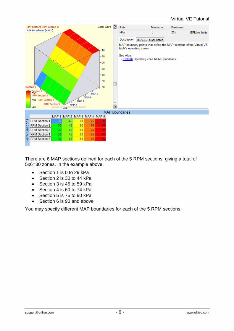
There are 6 MAP sections defined for each of the 5 RPM sections, giving a total of 5x6=30 zones. In the example above:
• Section 1 is 0 to 29 kPa • Section 2 is 30 to 44 kPa • Section 3 is 45 to 59 kPa • Section 4 is 60 to 74 kPa • Section 5 is 75 to 90 kPa • Section 6 is 90 and above
You may specify different MAP boundaries for each of the 5 RPM sections.
[email protected] www.efilive.com - 6 -

Virtual VE Tutorial
Identifying Zones The EFILive software highlights the zones using a subtle shading of the table and 3D colour schemes. The shading produces a checkerboard pattern that highlights the zone boundaries. The actual zone number (although not critically important) is shown in the upper left corner of the 3D surface plot.
Zones are numbered from 1 to 30 from right to left and from top to bottom of the Virtual VE Table data. EFILive tracks the current RPM, MAP and zone number in the upper left corner of the 3D surface plot. The current cell value is displayed in the upper right corner of the 3D surface plot.
Not all VE values can be represented within a single zone. Sharp peaks and valleys cannot be mathematically modelled by the coefficients and polynomial. They will be reduced to smooth lumps and/or hollows during the Virtual VE Table to coefficients conversion.
[email protected] www.efilive.com - 7 -

Virtual VE Tutorial
Editing the Virtual VE Table This (contrived) example shows you how to edit the Virtual VE Table, update the coefficients and refresh the Virtual VE Table using the newly updated coefficients. It will also show the importance of boundary edge alignment. The example shows a trivial adjustment to a rectangular section of cells in the Virtual VE table. The 3D surface plot has been zoomed and panned to display greater detail.
Select the cells shown in the image. The RPM and MAP ranges of the selection are shown in the top left corner of the 3D surface plot and the value of the top left selected cell is shown in the top right corner. The selection includes RPM 2000 to 2600 inclusive and MAP 37 to 47 inclusive. The Zone of the top left corner of the selected cells is 14.
[email protected] www.efilive.com - 8 -

Virtual VE Tutorial
Enter 2000 into the adjustment text box on the tool bar and click the toolbar button.
A red exclamation mark appears next to the coefficients’ Generate button. That means the Virtual VE Table has been modified but the coefficients have not yet been updated. You may select the Auto update coefficients checkbox and EFILive will automatically update the coefficients each time a change is made to the Virtual VE Table. Make sure the Zone edge align value is set to 0, then click on the coefficients’ Generate button. The red exclamation mark will disappear and the corresponding zones that have been modified in the Virtual VE Table will be updated in the coefficients table. In this case, zones 14, 15, 20 and 21. The modified cells are shown with blue flashes in their corners.
[email protected] www.efilive.com - 9 -

Virtual VE Tutorial
Next, to see how closely the newly calculated coefficients model the requested change, click on the Virtual VE Table’s Generate button.
The first thing you’ll notice is that the square shape that was requested has been replaced by a rounded bump. The bump is the closest approximation to the square shape that the polynomial and coefficients can mathematically produce.
[email protected] www.efilive.com - 10 -

Virtual VE Tutorial
Notice the edge boundary between zone 14 and 15. It contains some nasty holes that we don’t want.
Now, try generating the coefficients again with Zone edge align set to 1. Click the Undo toolbar button and enter 1 into the Zone edge align, then click the coefficients’ Generate button again. To see how closely the newly calculated coefficients model the requested change, click on the Virtual VE Table’s Generate button.
This time the nasty holes have been replaced with a smooth zone boundary transition.
[email protected] www.efilive.com - 11 -

Virtual VE Tutorial
Editing the Coefficients Table It is not advisable to edit the coefficients table directly unless you have a thorough understanding of how the coefficients are used to generate the Virtual VE Table.
Any changes that you make to the coefficients table will be overwritten when you click on the coefficients’ Generate button.
If you change any coefficient in a zone (i.e. in a single row of the table) then those zones will be modified in the Virtual VE Table when you click on the Virtual VE Table‘s Generate.
[email protected] www.efilive.com - 12 -

Virtual VE Tutorial
Forced Induction Applications Most stock calibrations are only tuned up to 105 kPa, which is perfectly acceptable for naturally aspirated engines. However, if you look at the 2 or 3-bar Virtual VE Tables for most stock tunes you will find some interesting and potentially dangerous values. For example, the Virtual VE table shown below is from a stock, naturally aspirated vehicle. If we request the 2-bar Virtual VE Table, it is plain to see that between 800 and 3200 rpm, and from 90 kPa and above the Virtual VE Table values would drop away causing a dangerously lean condition if the engine was operated under boost.
If you want to operate the engine under boost, then you MUST correct these types of anomalies by reshaping the Virtual VE Table and generating the coefficients again.
[email protected] www.efilive.com - 13 -

Virtual VE Tutorial
To do that, select the problem area and click on the two-way linear-fill toolbar icon.
Then apply some smoothing using the EFILive smoothing tool bar icon.
Then click the coefficients’ Generate button. To see how closely the newly calculated coefficients model the requested change, click on the Virtual VE Table’s Generate button.
[email protected] www.efilive.com - 14 -

Virtual VE Tutorial
Undo and Redo Considerations Unlike other tables, the Virtual VE and coefficient tables have an extra source of data. The Virtual VE Table can be generated from the coefficients table and the coefficients table can be generated from the Virtual VE Table. Each of the generated data cycles is also stored in the undo buffer so that you can undo the results of a generate cycle. Each of the user modifications is stored in an undo buffer so that you can click the undo/redo icon in the tool bar to undo and redo any changes that you make manually. The undo/redo actions are not synchronized between the two tables. If you click on either Generate button and then click undo, only the visible table’s data is undone. To undo the generated data in the other table, you must make that other table visible and then click on the undo toolbar icon to undo any changes in that table.
[email protected] www.efilive.com - 15 -

Virtual VE Tutorial
Limitations
Virtual VE Table Shape Limitations Each Virtual VE Table zone can only support one continuous curve in the RPM direction and one continuous curve in the MAP direction. A curve cannot change from convex to concave within a single zone. Large peaks or valleys at the corners of a zone will usually adversely affect the other corners of the same zone. Outlying or spiked data will be smoothed when generating coefficients.
Variable Position Cam Shaft Not Supported The software does not yet have the ability to factor in cam phasing (if the engine has it fitted). Cam phasing is always assumed to be 0 deg. The majority of Gen-IV engines do not use cam phasing. However, work is already underway to implement cam phasing into the Virtual VE Tables.
Generating 1-Bar Coefficients will Overwrite 2 and 3-Bar Data If you are working on a 2-bar Virtual VE Table and you open the 1-bar Virtual VE Table and update the coefficients then you will lose all the Virtual VE Table data for MAP values above the limit of the 1-bar table. The same thing occurs if you are working on a 3-bar table and you open a 1-bar or 2-bar table and generate coefficients. If you do accidentally do that, close all the Virtual VE Tables, open the coefficients table and select Undo. Then re-open the correct 2 or 3 bar Virtual VE table and it should be restored.
Large 2 and 3 bar Virtual VE Tables Large 2 and 3 bar Virtual VE Tables require additional memory. With multiple 3-bar tables open, the memory requirements of EFILive can exceed 80Mb. We recommend using a computer with 512Mb or more of memory.
[email protected] www.efilive.com - 16 -