vinyl sliding glass door assembly instructions · vinyl sliding glass door assembly instructions...
TRANSCRIPT
Vinyl Sliding Glass DoorAssembly Instructions
S E R I E S S G D 5 4 7 0 / 5 5 7 0
Vinyl Sliding Glass Door Assembly InstructionsS E R I E S S G D 5 4 7 0 / 5 5 7 0
PGTINDUSTRIES.COM | N. VENICE, FL
©2017 PGT CUSTOM WINDOWS + DOORS
05/17 ME0300210
0081-0070-assembly-instructions-v3.indd 3-4 5/2/17 11:26 AM
Para instrucciones en español, visite: http://bit.ly/PGTAssemblyInstructions
SGD 5470 / 5570
SGD 5470 / 5570 Parts List
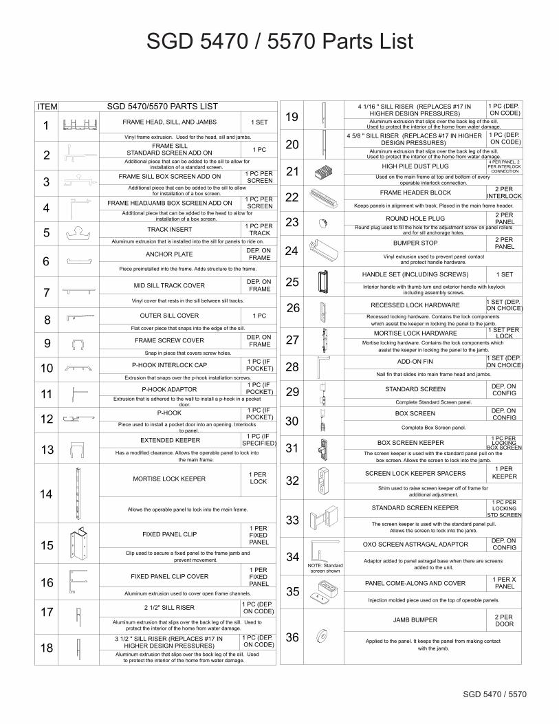
SGD 5470/5570 PARTS LIST
FRAME HEAD, SILL, AND JAMBS 1 SET
Vinyl frame extrusion. Used for the head, sill and jambs.
FRAME SILLSTANDARD SCREEN ADD ON 1 PC
Additional piece that can be added to the sill to allow for installation of a standard screen.
FRAME SILL BOX SCREEN ADD ON 1 PC PER SCREEN
Additional piece that can be added to the sill to allow for installation of a box screen.
FRAME HEAD/JAMB BOX SCREEN ADD ON 1 PC PER SCREEN
Additional piece that can be added to the head to allow for installation of a box screen.
TRACK INSERT 1 PC PER TRACK
Aluminum extrusion that is installed into the sill for panels to ride on.
ANCHOR PLATE DEP. ON FRAME
DEP. ON FRAME
DEP. ON FRAME
Piece preinstalled into the frame. Adds structure to the frame.
MID SILL TRACK COVER
Vinyl cover that rests in the sill between sill tracks.
OUTER SILL COVER 1 PC
Flat cover piece that snaps into the edge of the sill.
FRAME SCREW COVER
P-HOOK INTERLOCK CAP 1 PC (IF POCKET)
P-HOOK ADAPTOR1 PC (IF POCKET)
P-HOOK 1 PC (IF POCKET)
EXTENDED KEEPER 1 PC (IF SPECIFIED)
Has a modified clearance. Allows the operable panel to lock into the main frame.
MORTISE LOCK KEEPER1 PER LOCK
Allows the operable panel to lock into the main frame.
FIXED PANEL CLIP1 PER FIXED PANEL
1 PER FIXED PANEL
Clip used to secure a fixed panel to the frame jamb andprevent movement.
FIXED PANEL CLIP COVER
Aluminum extrusion used to cover open frame channels.
2 1/2" SILL RISER 1 PC (DEP. ON CODE)
Aluminum extrusion that slips over the back leg of the sill. Used to protect the interior of the home from water damage.
MORTISE LOCK HARDWAREMortise locking hardware. Contains the lock components which
assist the keeper in locking the panel to the jamb.
RECESSED LOCK HARDWARE
1 SET PER LOCK
Recessed locking hardware. Contains the lock components which assist the keeper in locking the panel to the jamb.
Snap in piece that covers screw holes.
Extrusion that snaps over the p-hook installation screws.
Extrusion that is adhered to the wall to install a p-hook in a pocket door.
Piece used to install a pocket door into an opening. Interlocks to panel.
ITEM
1
2
3
4
5
6
7
8
9
10
11
12
13
14
15
16
17
19
20
21
22
23
24
25
26
27
28
29
30
31
32
33
34
3 1/2 " SILL RISER (REPLACES #17 IN HIGHER DESIGN PRESSURES)
Aluminum extrusion that slips over the back leg of the sill. Used to protect the interior of the home from water damage.
4 1/16 " SILL RISER (REPLACES #17 IN HIGHER DESIGN PRESSURES)Aluminum extrusion that slips over the back leg of the sill.
Used to protect the interior of the home from water damage.
Aluminum extrusion that slips over the back leg of the sill.Used to protect the interior of the home from water damage.
4 5/8 " SILL RISER (REPLACES #17 IN HIGHER DESIGN PRESSURES)
HIGH PILE DUST PLUG4 PER PANEL, 2 PER INTERLOCK
CONNECTIONUsed on the main frame at top and bottom of every
operable interlock connection.
FRAME HEADER BLOCK 2 PER INTERLOCK
Keeps panels in alignment with track. Placed in the main frame header.
ROUND HOLE PLUG 2 PER PANEL
Round plug used to fill the hole for the adjustment screw on panel rollersand for sill anchorage holes.
BUMPER STOP
Vinyl extrusion used to prevent panel contactand protect handle hardware.
HANDLE SET (INCLUDING SCREWS) 1 SET
Interior handle with thumb turn and exterior handle with keylockincluding assembly screws.
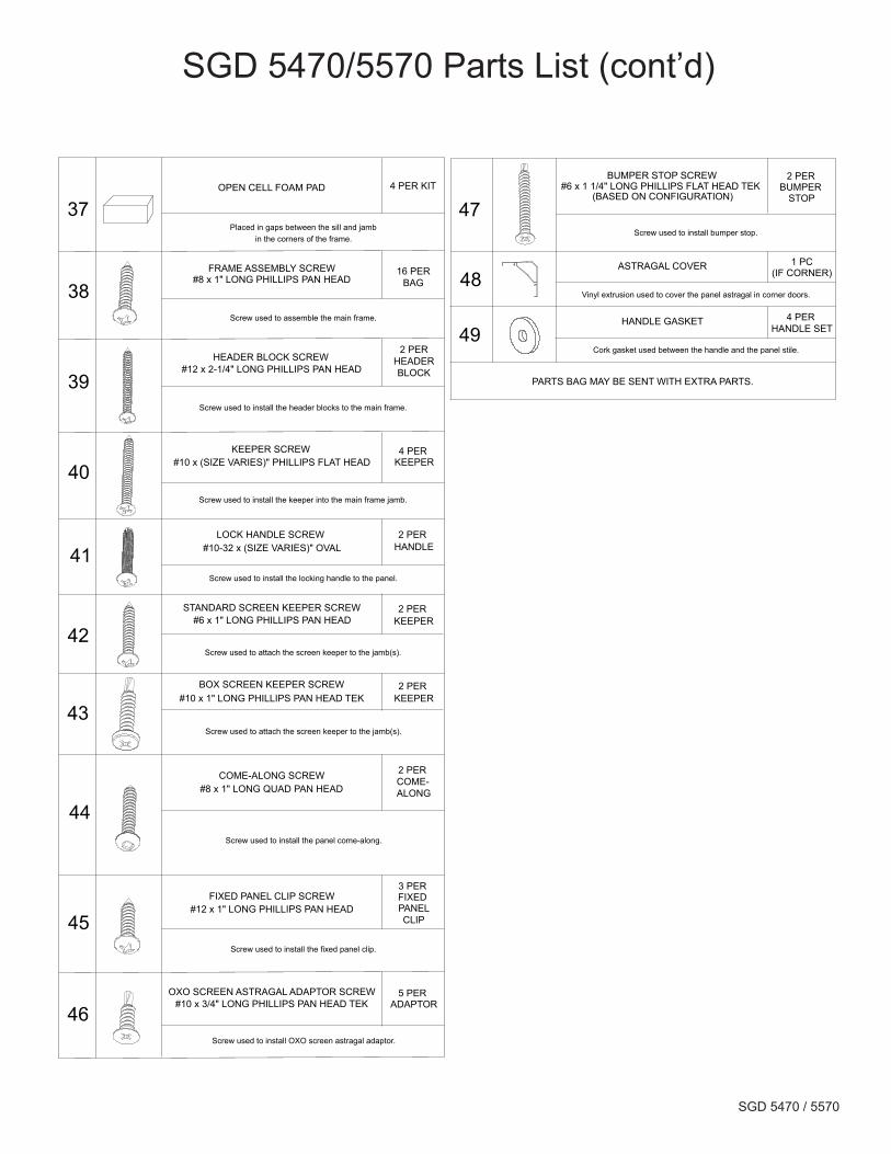
FRAME ASSEMBLY SCREW#8 x 1" LONG PHILLIPS PAN HEAD
16 PERBAG
2 PERHEADERBLOCK
Screw used to assemble the main frame.
FIXED PANEL CLIP SCREW#12 x 1" LONG PHILLIPS PAN HEAD
Screw used to install the fixed panel clip.
HEADER BLOCK SCREW#12 x 2-1/4" LONG PHILLIPS PAN HEAD
Screw used to install the header blocks to the main frame.
KEEPER SCREW#10 x (SIZE VARIES)" PHILLIPS FLAT HEAD
4 PER KEEPER
Screw used to install the keeper into the main frame jamb.
JAMB BUMPER
Applied to the panel. It keeps the panel from making contact with the jamb.
PANEL COME-ALONG AND COVER
Injection molded piece used on the top of operable panels.
1 PC (DEP. ON CODE)
1 PC (DEP. ON CODE)
1 PC (DEP. ON CODE)
2 PER PANEL
3 PER FIXED PANELCLIP
COME-ALONG SCREW#8 x 1" LONG QUAD PAN HEAD
2 PER COME-ALONG
Screw used to install the panel come-along.
OPEN CELL FOAM PAD
Placed in gaps between the sill and jambin the corners of the frame.
2 PER DOOR
1 PER X PANEL
4 PER KIT
18
SCREEN LOCK KEEPER SPACERS
Shim used to raise screen keeper off of frame for additional adjustment.
1 PER KEEPER
BOX SCREEN KEEPER SCREW#10 x 1" LONG PHILLIPS PAN HEAD TEK
Screw used to attach the screen keeper to the jamb(s).
2 PER KEEPER
35
36
BOX SCREEN DEP. ON CONFIG
Complete Box Screen panel.
37
STANDARD SCREEN DEP. ON CONFIG
Complete Standard Screen panel.
BOX SCREEN KEEPER
The screen keeper is used with the standard panel pull on the box screen. Allows the screen to lock into the jamb.
38
39
40
41
42
STANDARD SCREEN KEEPER1 PC PER LOCKING
STD SCREEN
1 PC PER LOCKING
BOX SCREEN
The screen keeper is used with the standard panel pull.Allows the screen to lock into the jamb.
STANDARD SCREEN KEEPER SCREW#6 x 1" LONG PHILLIPS PAN HEAD
2 PER KEEPER
Screw used to attach the screen keeper to the jamb(s).
43
2 PER HANDLE
LOCK HANDLE SCREW #10-32 x (SIZE VARIES)" OVAL
Screw used to install the locking handle to the panel.
44
45NOTE: Standard
screen shown
OXO SCREEN ASTRAGAL ADAPTOR
Adaptor added to panel astragal base when there are screens added to the unit.
OXO SCREEN ASTRAGAL ADAPTOR SCREW#10 x 3/4" LONG PHILLIPS PAN HEAD TEK
Screw used to install OXO screen astragal adaptor.
5 PER ADAPTOR
DEP. ON CONFIG
46
BUMPER STOP SCREW#6 x 1 1/4" LONG PHILLIPS FLAT HEAD TEK
(BASED ON CONFIGURATION)
2 PER BUMPER
STOP
Screw used to install bumper stop.
47
ADD-ON FIN 1 SET (DEP. ON CHOICE)
1 SET (DEP. ON CHOICE)
Nail fin that slides into main frame head and jambs.
PARTS BAG MAY BE SENT WITH EXTRA PARTS.
ASTRAGAL COVER 1 PC(IF CORNER)
Vinyl extrusion used to cover the panel astragal in corner doors.48
HANDLE GASKET 4 PER HANDLE SET
Cork gasket used between the handle and the panel stile.49
SGD 5470 / 5570
SGD 5470/5570 Parts List (cont’d)
SGD 5470/5570 PARTS LIST
FRAME HEAD, SILL, AND JAMBS 1 SET
Vinyl frame extrusion. Used for the head, sill and jambs.
FRAME SILLSTANDARD SCREEN ADD ON 1 PC
Additional piece that can be added to the sill to allow for installation of a standard screen.
FRAME SILL BOX SCREEN ADD ON 1 PC PER SCREEN
Additional piece that can be added to the sill to allow for installation of a box screen.
FRAME HEAD/JAMB BOX SCREEN ADD ON 1 PC PER SCREEN
Additional piece that can be added to the head to allow for installation of a box screen.
TRACK INSERT 1 PC PER TRACK
Aluminum extrusion that is installed into the sill for panels to ride on.
ANCHOR PLATE DEP. ON FRAME
DEP. ON FRAME
DEP. ON FRAME
Piece preinstalled into the frame. Adds structure to the frame.
MID SILL TRACK COVER
Vinyl cover that rests in the sill between sill tracks.
OUTER SILL COVER 1 PC
Flat cover piece that snaps into the edge of the sill.
FRAME SCREW COVER
P-HOOK INTERLOCK CAP 1 PC (IF POCKET)
P-HOOK ADAPTOR1 PC (IF POCKET)
P-HOOK 1 PC (IF POCKET)
EXTENDED KEEPER 1 PC (IF SPECIFIED)
Has a modified clearance. Allows the operable panel to lock into the main frame.
MORTISE LOCK KEEPER1 PER LOCK
Allows the operable panel to lock into the main frame.
FIXED PANEL CLIP1 PER FIXED PANEL
1 PER FIXED PANEL
Clip used to secure a fixed panel to the frame jamb andprevent movement.
FIXED PANEL CLIP COVER
Aluminum extrusion used to cover open frame channels.
2 1/2" SILL RISER 1 PC (DEP. ON CODE)
Aluminum extrusion that slips over the back leg of the sill. Used to protect the interior of the home from water damage.
MORTISE LOCK HARDWAREMortise locking hardware. Contains the lock components which
assist the keeper in locking the panel to the jamb.
RECESSED LOCK HARDWARE
1 SET PER LOCK
Recessed locking hardware. Contains the lock components which assist the keeper in locking the panel to the jamb.
Snap in piece that covers screw holes.
Extrusion that snaps over the p-hook installation screws.
Extrusion that is adhered to the wall to install a p-hook in a pocket door.
Piece used to install a pocket door into an opening. Interlocks to panel.
ITEM
1
2
3
4
5
6
7
8
9
10
11
12
13
14
15
16
17
19
20
21
22
23
24
25
26
27
28
29
30
31
32
33
34
3 1/2 " SILL RISER (REPLACES #17 IN HIGHER DESIGN PRESSURES)
Aluminum extrusion that slips over the back leg of the sill. Used to protect the interior of the home from water damage.
4 1/16 " SILL RISER (REPLACES #17 IN HIGHER DESIGN PRESSURES)Aluminum extrusion that slips over the back leg of the sill.
Used to protect the interior of the home from water damage.
Aluminum extrusion that slips over the back leg of the sill.Used to protect the interior of the home from water damage.
4 5/8 " SILL RISER (REPLACES #17 IN HIGHER DESIGN PRESSURES)
HIGH PILE DUST PLUG4 PER PANEL, 2 PER INTERLOCK
CONNECTIONUsed on the main frame at top and bottom of every
operable interlock connection.
FRAME HEADER BLOCK 2 PER INTERLOCK
Keeps panels in alignment with track. Placed in the main frame header.
ROUND HOLE PLUG 2 PER PANEL
Round plug used to fill the hole for the adjustment screw on panel rollersand for sill anchorage holes.
BUMPER STOP
Vinyl extrusion used to prevent panel contactand protect handle hardware.
HANDLE SET (INCLUDING SCREWS) 1 SET
Interior handle with thumb turn and exterior handle with keylockincluding assembly screws.
FRAME ASSEMBLY SCREW#8 x 1" LONG PHILLIPS PAN HEAD
16 PERBAG
2 PERHEADERBLOCK
Screw used to assemble the main frame.
FIXED PANEL CLIP SCREW#12 x 1" LONG PHILLIPS PAN HEAD
Screw used to install the fixed panel clip.
HEADER BLOCK SCREW#12 x 2-1/4" LONG PHILLIPS PAN HEAD
Screw used to install the header blocks to the main frame.
KEEPER SCREW#10 x (SIZE VARIES)" PHILLIPS FLAT HEAD
4 PER KEEPER
Screw used to install the keeper into the main frame jamb.
JAMB BUMPER
Applied to the panel. It keeps the panel from making contact with the jamb.
PANEL COME-ALONG AND COVER
Injection molded piece used on the top of operable panels.
1 PC (DEP. ON CODE)
1 PC (DEP. ON CODE)
1 PC (DEP. ON CODE)
2 PER PANEL
3 PER FIXED PANELCLIP
COME-ALONG SCREW#8 x 1" LONG QUAD PAN HEAD
2 PER COME-ALONG
Screw used to install the panel come-along.
OPEN CELL FOAM PAD
Placed in gaps between the sill and jambin the corners of the frame.
2 PER DOOR
1 PER X PANEL
4 PER KIT
18
SCREEN LOCK KEEPER SPACERS
Shim used to raise screen keeper off of frame for additional adjustment.
1 PER KEEPER
BOX SCREEN KEEPER SCREW#10 x 1" LONG PHILLIPS PAN HEAD TEK
Screw used to attach the screen keeper to the jamb(s).
2 PER KEEPER
35
36
BOX SCREEN DEP. ON CONFIG
Complete Box Screen panel.
37
STANDARD SCREEN DEP. ON CONFIG
Complete Standard Screen panel.
BOX SCREEN KEEPER
The screen keeper is used with the standard panel pull on the box screen. Allows the screen to lock into the jamb.
38
39
40
41
42
STANDARD SCREEN KEEPER1 PC PER LOCKING
STD SCREEN
1 PC PER LOCKING
BOX SCREEN
The screen keeper is used with the standard panel pull.Allows the screen to lock into the jamb.
STANDARD SCREEN KEEPER SCREW#6 x 1" LONG PHILLIPS PAN HEAD
2 PER KEEPER
Screw used to attach the screen keeper to the jamb(s).
43
2 PER HANDLE
LOCK HANDLE SCREW #10-32 x (SIZE VARIES)" OVAL
Screw used to install the locking handle to the panel.
44
45NOTE: Standard
screen shown
OXO SCREEN ASTRAGAL ADAPTOR
Adaptor added to panel astragal base when there are screens added to the unit.
OXO SCREEN ASTRAGAL ADAPTOR SCREW#10 x 3/4" LONG PHILLIPS PAN HEAD TEK
Screw used to install OXO screen astragal adaptor.
5 PER ADAPTOR
DEP. ON CONFIG
46
BUMPER STOP SCREW#6 x 1 1/4" LONG PHILLIPS FLAT HEAD TEK
(BASED ON CONFIGURATION)
2 PER BUMPER
STOP
Screw used to install bumper stop.
47
ADD-ON FIN 1 SET (DEP. ON CHOICE)
1 SET (DEP. ON CHOICE)
Nail fin that slides into main frame head and jambs.
PARTS BAG MAY BE SENT WITH EXTRA PARTS.
ASTRAGAL COVER 1 PC(IF CORNER)
Vinyl extrusion used to cover the panel astragal in corner doors.48
HANDLE GASKET 4 PER HANDLE SET
Cork gasket used between the handle and the panel stile.49
SGD 5470 / 5570
1
1
6
28
38
57
3717
9
38
39
22
10
410 12
2 7
6
537
17
1
11
BYPASSDOOR
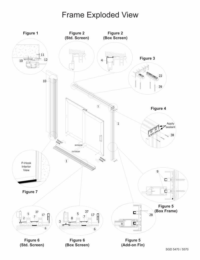
Frame Exploded View
POCKETDOOR
INTERIOR
EXTERIOR
Frame Exploded View
Figure 1 Figure 2(Std. Screen)
Figure 2(Box Screen)
Figure 3
Figure 4
Figure 5(Add-on Fin)
Figure 5(Box Frame)
Figure 6(Box Screen)
Figure 6(Std. Screen)
Figure 7
Apply sealant
P-Hook Interior View
SGD 5470 / 5570
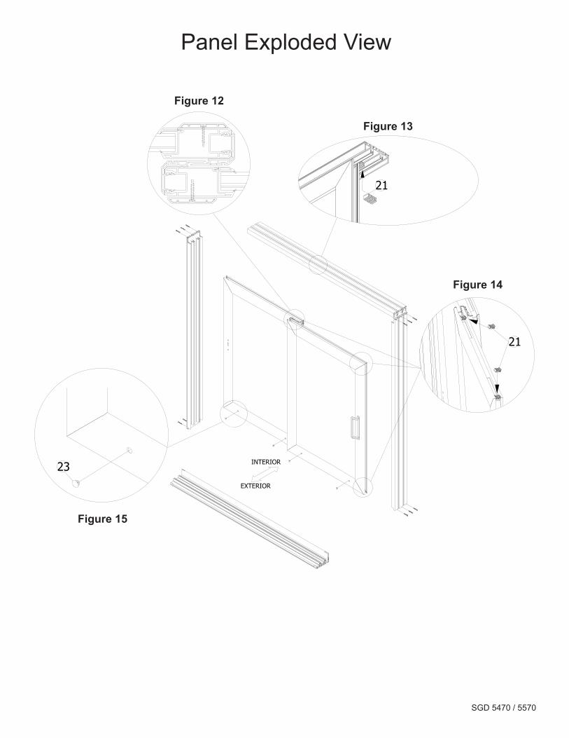
Panel Exploded View
Figure 12
Figure 13
Figure 14
Figure 15
21
21
23 INTERIOR
EXTERIOR
Panel Exploded View
SGD 5470 / 5570
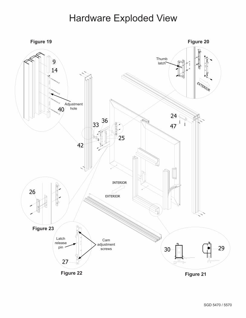
Hardware Exploded View
Figure 19 Figure 20
Figure 21Figure 22
Figure 23
Cam adjustment
screws
Thumb latch
Adjustment hole
Latch release
pin
47
42
3336
25
24
30 29
27
26
40
149
EXTERIOR
Hardware Exploded View
INTERIOR
EXTERIOR
SGD 5470 / 5570
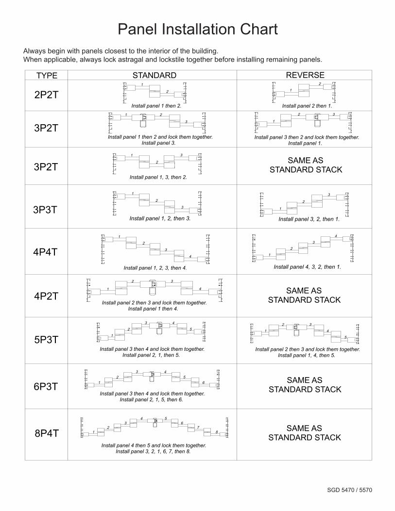
Panel Installation ChartAlways begin with panels closest to the interior of the building.When applicable, always lock astragal and lockstile together before installing remaining panels.
Always start with panels closest to the interior of the building. When applicable, always lock astragal and lockstile together before installing remaining panels.
1
2 1
2
Panel Installation Chart
1 2
3
Install panel 1 then 2 and lock them together. Install panel 3.
1
2 3
1
2
3 1
2
3
1
2
3
4 1
2
3
4
1
2 3
4
12
3 45
6
TYPE STANDARD REVERSE
12
34 5
67
8
Install panel 3 then 2 and lock them together. Install panel 1.
Install panel 2 then 3 and lock them together. Install panel 1 then 4.
Install panel 3 then 4 and lock them together. Install panel 2, 1, 5, then 6.
Install panel 4 then 5 and lock them together. Install panel 3, 2, 1, 6, 7, then 8.
1
2
3 4
5
Install panel 3 then 4 and lock them together. Install panel 2, 1, then 5.
Install panel 2 then 3 and lock them together. Install panel 1, 4, then 5.
Install panel 1, 2, 3, then 4. Install panel 4, 3, 2, then 1.
Install panel 1, 2, then 3. Install panel 3, 2, then 1.
Install panel 1 then 2. Install panel 2 then 1.
SAME ASSTANDARD STACK
SAME ASSTANDARD STACK
SAME ASSTANDARD STACK
2P2T
3P2T
3P3T
4P4T
4P2T
5P3T
6P3T
8P4T
5
4
32
1
3P2T 1
2
Install panel 1, 3, then 2.
3
SAME ASSTANDARD STACK
SGD 5470 / 5570
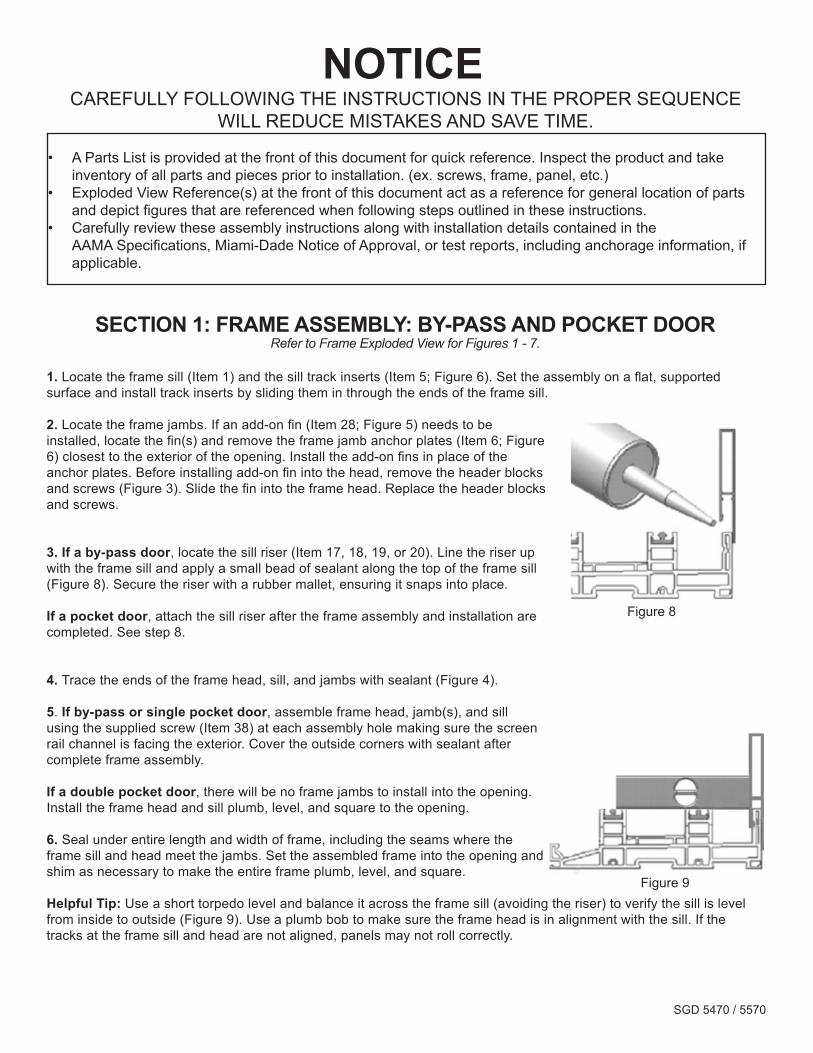
NOTICE CAREFULLY FOLLOWING THE INSTRUCTIONS IN THE PROPER SEQUENCE
WILL REDUCE MISTAKES AND SAVE TIME.
• A Parts List is provided at the front of this document for quick reference. Inspect the product and take inventory of all parts and pieces prior to installation. (ex. screws, frame, panel, etc.)
• Exploded View Reference(s) at the front of this document act as a reference for general location of parts and depict figures that are referenced when following steps outlined in these instructions.
• Carefully review these assembly instructions along with installation details contained in the AAMA Specifications, Miami-Dade Notice of Approval, or test reports, including anchorage information, if applicable.
SECTION 1: FRAME ASSEMBLY: BY-PASS AND POCKET DOORRefer to Frame Exploded View for Figures 1 - 7.
1. Locate the frame sill (Item 1) and the sill track inserts (Item 5; Figure 6). Set the assembly on a flat, supported surface and install track inserts by sliding them in through the ends of the frame sill.
2. Locate the frame jambs. If an add-on fin (Item 28; Figure 5) needs to be installed, locate the fin(s) and remove the frame jamb anchor plates (Item 6; Figure 6) closest to the exterior of the opening. Install the add-on fins in place of the anchor plates. Before installing add-on fin into the head, remove the header blocks and screws (Figure 3). Slide the fin into the frame head. Replace the header blocks and screws.
3. If a by-pass door, locate the sill riser (Item 17, 18, 19, or 20). Line the riser up with the frame sill and apply a small bead of sealant along the top of the frame sill (Figure 8). Secure the riser with a rubber mallet, ensuring it snaps into place.
If a pocket door, attach the sill riser after the frame assembly and installation are completed. See step 8.
4. Trace the ends of the frame head, sill, and jambs with sealant (Figure 4).
5. If by-pass or single pocket door, assemble frame head, jamb(s), and sill using the supplied screw (Item 38) at each assembly hole making sure the screen rail channel is facing the exterior. Cover the outside corners with sealant after complete frame assembly.
If a double pocket door, there will be no frame jambs to install into the opening. Install the frame head and sill plumb, level, and square to the opening.
6. Seal under entire length and width of frame, including the seams where the frame sill and head meet the jambs. Set the assembled frame into the opening and shim as necessary to make the entire frame plumb, level, and square.
Helpful Tip: Use a short torpedo level and balance it across the frame sill (avoiding the riser) to verify the sill is level from inside to outside (Figure 9). Use a plumb bob to make sure the frame head is in alignment with the sill. If the tracks at the frame sill and head are not aligned, panels may not roll correctly.
Figure 8
Figure 9
SGD 5470 / 5570
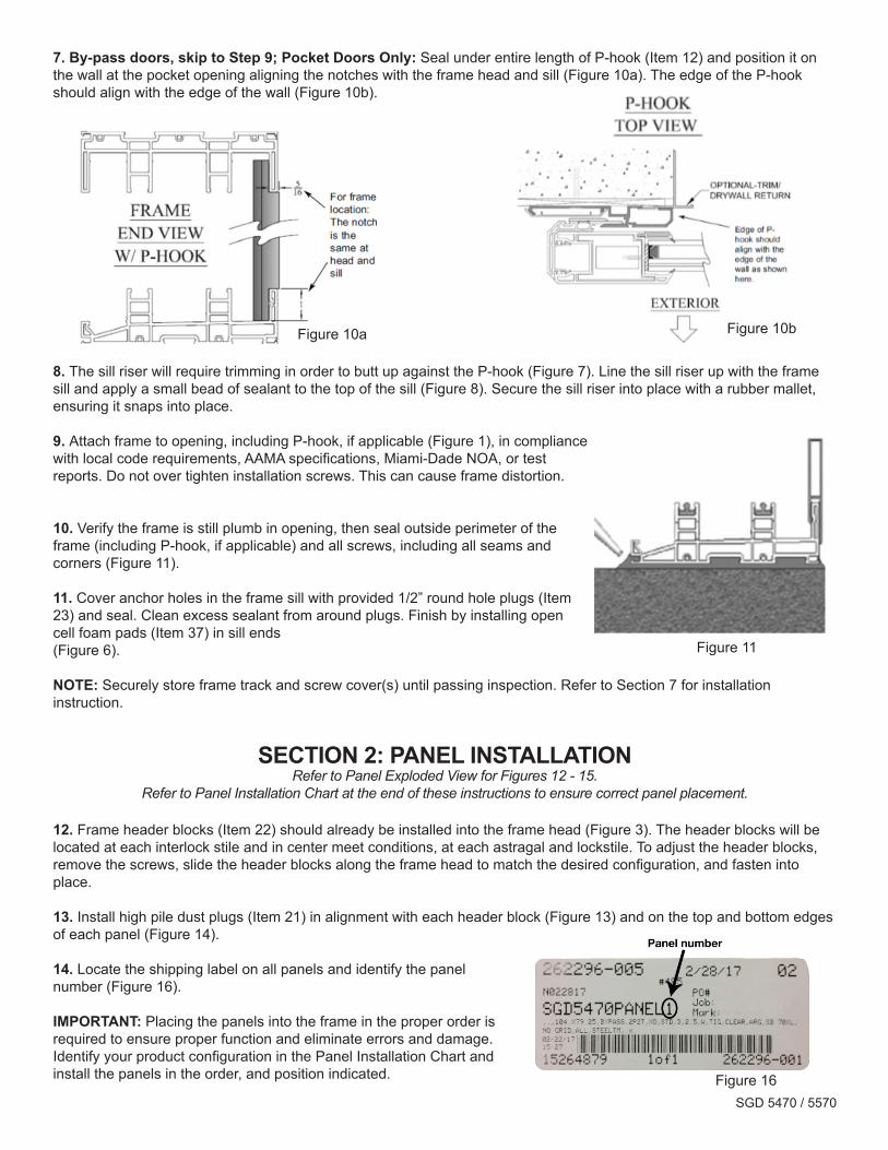
7. By-pass doors, skip to Step 9; Pocket Doors Only: Seal under entire length of P-hook (Item 12) and position it on the wall at the pocket opening aligning the notches with the frame head and sill (Figure 10a). The edge of the P-hook should align with the edge of the wall (Figure 10b).
8. The sill riser will require trimming in order to butt up against the P-hook (Figure 7). Line the sill riser up with the frame sill and apply a small bead of sealant to the top of the sill (Figure 8). Secure the sill riser into place with a rubber mallet, ensuring it snaps into place.
9. Attach frame to opening, including P-hook, if applicable (Figure 1), in compliance with local code requirements, AAMA specifications, Miami-Dade NOA, or test reports. Do not over tighten installation screws. This can cause frame distortion.
10. Verify the frame is still plumb in opening, then seal outside perimeter of the frame (including P-hook, if applicable) and all screws, including all seams and corners (Figure 11).
11. Cover anchor holes in the frame sill with provided 1/2” round hole plugs (Item 23) and seal. Clean excess sealant from around plugs. Finish by installing open cell foam pads (Item 37) in sill ends(Figure 6).
NOTE: Securely store frame track and screw cover(s) until passing inspection. Refer to Section 7 for installation instruction.
SECTION 2: PANEL INSTALLATION
Refer to Panel Exploded View for Figures 12 - 15.Refer to Panel Installation Chart at the end of these instructions to ensure correct panel placement.
12. Frame header blocks (Item 22) should already be installed into the frame head (Figure 3). The header blocks will be located at each interlock stile and in center meet conditions, at each astragal and lockstile. To adjust the header blocks, remove the screws, slide the header blocks along the frame head to match the desired configuration, and fasten into place.
13. Install high pile dust plugs (Item 21) in alignment with each header block (Figure 13) and on the top and bottom edges of each panel (Figure 14).
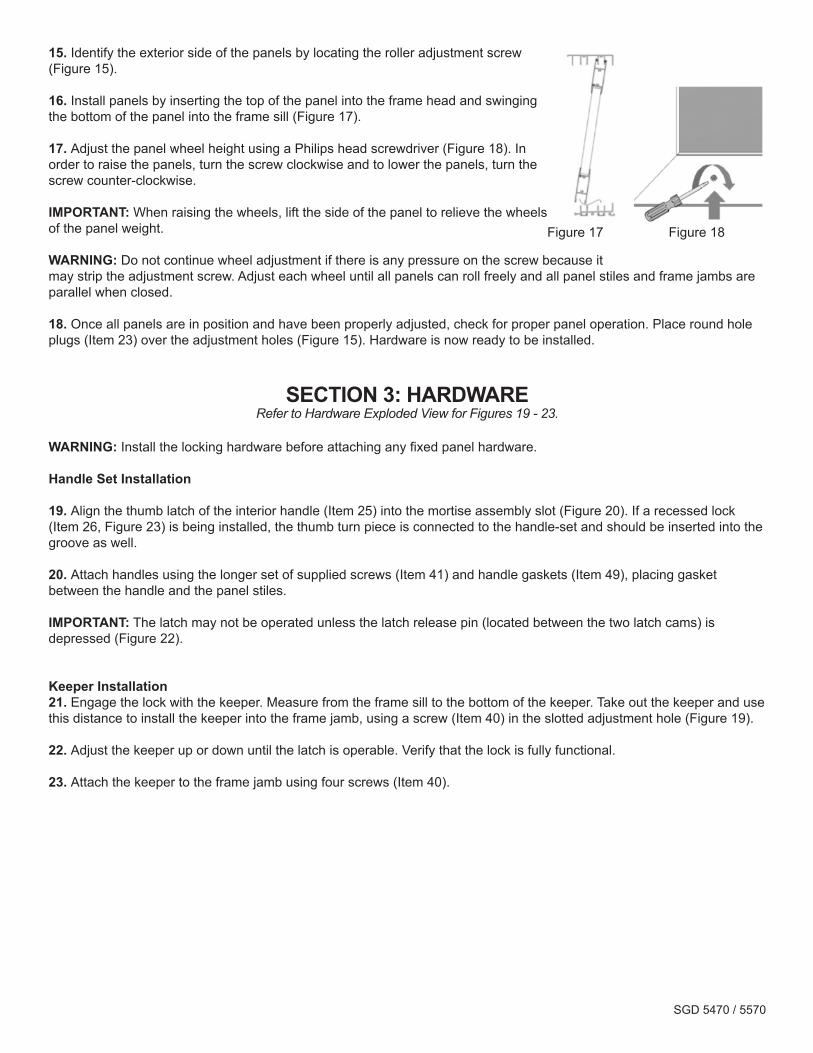
14. Locate the shipping label on all panels and identify the panel number (Figure 16).
IMPORTANT: Placing the panels into the frame in the proper order is required to ensure proper function and eliminate errors and damage. Identify your product configuration in the Panel Installation Chart and install the panels in the order, and position indicated.
Figure 10a Figure 10b
Figure 16
Figure 11
SGD 5470 / 5570
15. Identify the exterior side of the panels by locating the roller adjustment screw (Figure 15).
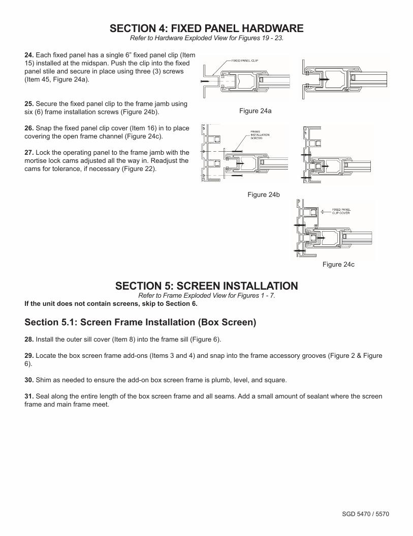
16. Install panels by inserting the top of the panel into the frame head and swinging the bottom of the panel into the frame sill (Figure 17).
17. Adjust the panel wheel height using a Philips head screwdriver (Figure 18). In order to raise the panels, turn the screw clockwise and to lower the panels, turn the screw counter-clockwise.
IMPORTANT: When raising the wheels, lift the side of the panel to relieve the wheels of the panel weight.
WARNING: Do not continue wheel adjustment if there is any pressure on the screw because it may strip the adjustment screw. Adjust each wheel until all panels can roll freely and all panel stiles and frame jambs are parallel when closed.
18. Once all panels are in position and have been properly adjusted, check for proper panel operation. Place round hole plugs (Item 23) over the adjustment holes (Figure 15). Hardware is now ready to be installed.
SECTION 3: HARDWARERefer to Hardware Exploded View for Figures 19 - 23.
WARNING: Install the locking hardware before attaching any fixed panel hardware.
Handle Set Installation
19. Align the thumb latch of the interior handle (Item 25) into the mortise assembly slot (Figure 20). If a recessed lock (Item 26, Figure 23) is being installed, the thumb turn piece is connected to the handle-set and should be inserted into the groove as well.
20. Attach handles using the longer set of supplied screws (Item 41) and handle gaskets (Item 49), placing gasket between the handle and the panel stiles.
IMPORTANT: The latch may not be operated unless the latch release pin (located between the two latch cams) is depressed (Figure 22).
Keeper Installation21. Engage the lock with the keeper. Measure from the frame sill to the bottom of the keeper. Take out the keeper and use this distance to install the keeper into the frame jamb, using a screw (Item 40) in the slotted adjustment hole (Figure 19).
22. Adjust the keeper up or down until the latch is operable. Verify that the lock is fully functional.
23. Attach the keeper to the frame jamb using four screws (Item 40).
Figure 18Figure 17
SGD 5470 / 5570
SECTION 4: FIXED PANEL HARDWARERefer to Hardware Exploded View for Figures 19 - 23.
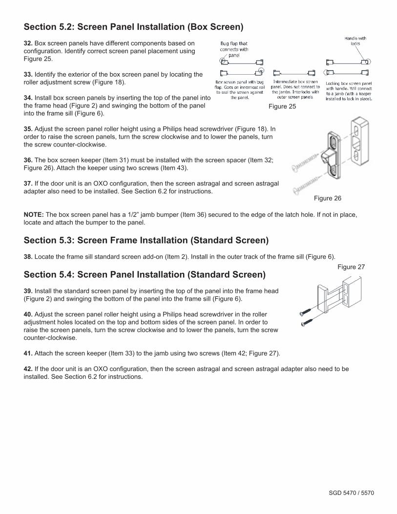
24. Each fixed panel has a single 6” fixed panel clip (Item 15) installed at the midspan. Push the clip into the fixed panel stile and secure in place using three (3) screws (Item 45, Figure 24a).
25. Secure the fixed panel clip to the frame jamb using six (6) frame installation screws (Figure 24b).
26. Snap the fixed panel clip cover (Item 16) in to place covering the open frame channel (Figure 24c).
27. Lock the operating panel to the frame jamb with the mortise lock cams adjusted all the way in. Readjust the cams for tolerance, if necessary (Figure 22).
SECTION 5: SCREEN INSTALLATIONRefer to Frame Exploded View for Figures 1 - 7.
If the unit does not contain screens, skip to Section 6.
Section 5.1: Screen Frame Installation (Box Screen)28. Install the outer sill cover (Item 8) into the frame sill (Figure 6).
29. Locate the box screen frame add-ons (Items 3 and 4) and snap into the frame accessory grooves (Figure 2 & Figure 6).
30. Shim as needed to ensure the add-on box screen frame is plumb, level, and square.
31. Seal along the entire length of the box screen frame and all seams. Add a small amount of sealant where the screen frame and main frame meet.
Figure 24a
Figure 24b
Figure 24c
SGD 5470 / 5570
Section 5.2: Screen Panel Installation (Box Screen)32. Box screen panels have different components based on configuration. Identify correct screen panel placement using Figure 25.
33. Identify the exterior of the box screen panel by locating the roller adjustment screw (Figure 18).
34. Install box screen panels by inserting the top of the panel into the frame head (Figure 2) and swinging the bottom of the panel into the frame sill (Figure 6).
35. Adjust the screen panel roller height using a Philips head screwdriver (Figure 18). In order to raise the screen panels, turn the screw clockwise and to lower the panels, turn the screw counter-clockwise.
36. The box screen keeper (Item 31) must be installed with the screen spacer (Item 32; Figure 26). Attach the keeper using two screws (Item 43).
37. If the door unit is an OXO configuration, then the screen astragal and screen astragal adapter also need to be installed. See Section 6.2 for instructions.
NOTE: The box screen panel has a 1/2” jamb bumper (Item 36) secured to the edge of the latch hole. If not in place, locate and attach the bumper to the panel.
Section 5.3: Screen Frame Installation (Standard Screen)38. Locate the frame sill standard screen add-on (Item 2). Install in the outer track of the frame sill (Figure 6).
Section 5.4: Screen Panel Installation (Standard Screen)39. Install the standard screen panel by inserting the top of the panel into the frame head (Figure 2) and swinging the bottom of the panel into the frame sill (Figure 6).
40. Adjust the screen panel roller height using a Philips head screwdriver in the roller adjustment holes located on the top and bottom sides of the screen panel. In order to raise the screen panels, turn the screw clockwise and to lower the panels, turn the screw counter-clockwise.
41. Attach the screen keeper (Item 33) to the jamb using two screws (Item 42; Figure 27).
42. If the door unit is an OXO configuration, then the screen astragal and screen astragal adapter also need to be installed. See Section 6.2 for instructions.
Figure 26
Figure 25
Figure 27
SGD 5470 / 5570
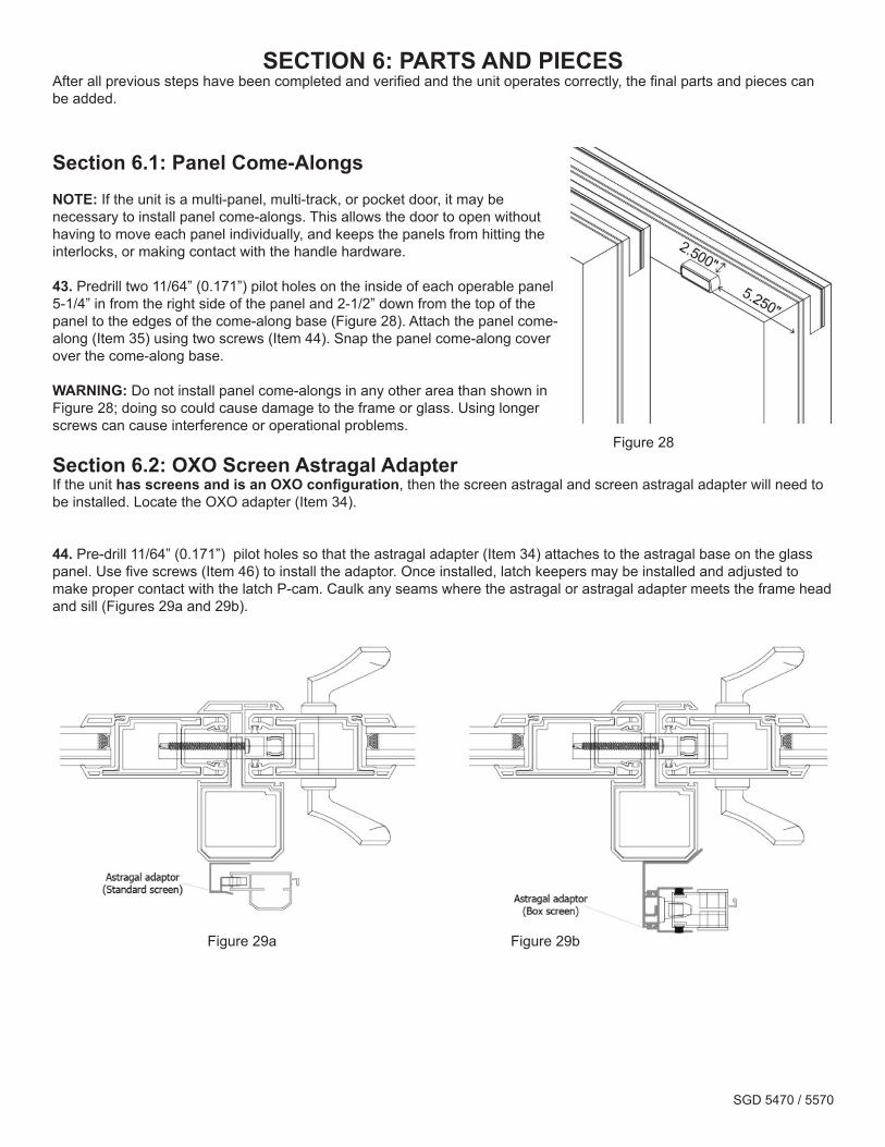
SECTION 6: PARTS AND PIECESAfter all previous steps have been completed and verified and the unit operates correctly, the final parts and pieces can be added.
Section 6.1: Panel Come-AlongsNOTE: If the unit is a multi-panel, multi-track, or pocket door, it may be necessary to install panel come-alongs. This allows the door to open without having to move each panel individually, and keeps the panels from hitting the interlocks, or making contact with the handle hardware.
43. Pre drill two 11/64” (0.171”) pilot holes on the inside of each operable panel 5-1/4” in from the right side of the panel and 2-1/2” down from the top of the panel to the edges of the come-along base (Figure 28). Attach the panel come-along (Item 35) using two screws (Item 44). Snap the panel come-along cover over the come-along base.
WARNING: Do not install panel come-alongs in any other area than shown in Figure 28; doing so could cause damage to the frame or glass. Using longer screws can cause interference or operational problems.
Section 6.2: OXO Screen Astragal AdapterIf the unit has screens and is an OXO configuration, then the screen astragal and screen astragal adapter will need to be installed. Locate the OXO adapter (Item 34).
44. Pre-drill 11/64” (0.171”) pilot holes so that the astragal adapter (Item 34) attaches to the astragal base on the glass panel. Use five screws (Item 46) to install the adaptor. Once installed, latch keepers may be installed and adjusted to make proper contact with the latch P-cam. Caulk any seams where the astragal or astragal adapter meets the frame head and sill (Figures 29a and 29b).
Figure 28
Figure 29bFigure 29a
SGD 5470 / 5570
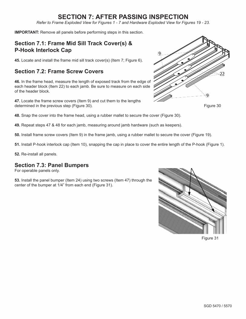
SECTION 7: AFTER PASSING INSPECTIONRefer to Frame Exploded View for Figures 1 - 7 and Hardware Exploded View for Figures 19 - 23.
IMPORTANT: Remove all panels before performing steps in this section.
Section 7.1: Frame Mid Sill Track Cover(s) & P-Hook Interlock Cap45. Locate and install the frame mid sill track cover(s) (Item 7; Figure 6).
Section 7.2: Frame Screw Covers46. In the frame head, measure the length of exposed track from the edge of each header block (Item 22) to each jamb. Be sure to measure on each side of the header block.
47. Locate the frame screw covers (Item 9) and cut them to the lengths determined in the previous step (Figure 30).
48. Snap the cover into the frame head, using a rubber mallet to secure the cover (Figure 30).
49. Repeat steps 47 & 48 for each jamb, measuring around jamb hardware (such as keepers).
50. Install frame screw covers (Item 9) in the frame jamb, using a rubber mallet to secure the cover (Figure 19).
51. Install P-hook interlock cap (Item 10), snapping the cap in place to cover the entire length of the P-hook (Figure 1).
52. Re-install all panels.
Section 7.3: Panel BumpersFor operable panels only.
53. Install the panel bumper (Item 24) using two screws (Item 47) through the center of the bumper at 1/4” from each end (Figure 31).
Figure 31
Figure 30
SGD 5470 / 5570
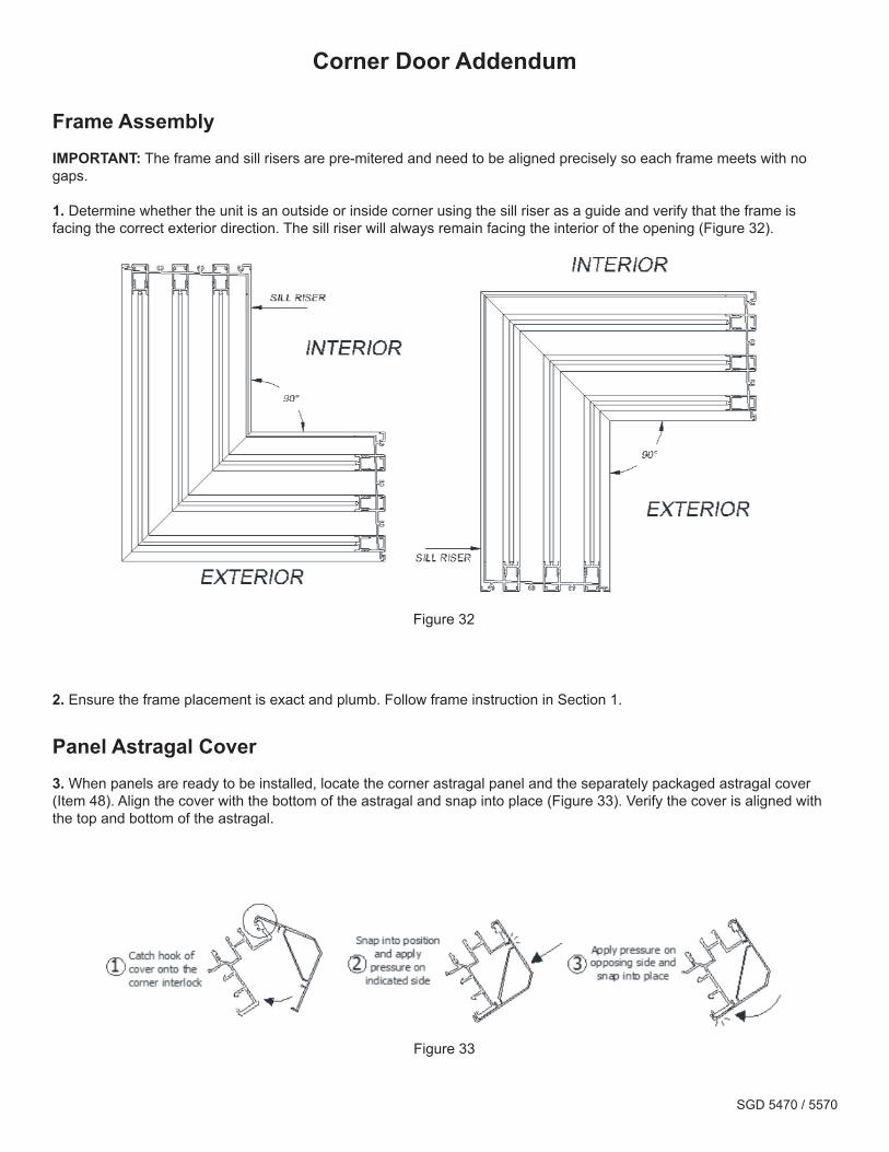
Corner Door Addendum
Frame AssemblyIMPORTANT: The frame and sill risers are pre-mitered and need to be aligned precisely so each frame meets with no gaps.
1. Determine whether the unit is an outside or inside corner using the sill riser as a guide and verify that the frame is facing the correct exterior direction. The sill riser will always remain facing the interior of the opening (Figure 32).
2. Ensure the frame placement is exact and plumb. Follow frame instruction in Section 1.
Panel Astragal Cover3. When panels are ready to be installed, locate the corner astragal panel and the separately packaged astragal cover (Item 48). Align the cover with the bottom of the astragal and snap into place (Figure 33). Verify the cover is aligned with the top and bottom of the astragal.
Figure 32
Figure 33

09/17 ME0300210
PGTINDUSTRIES.COM N. VENICE, FL
©2017 PGT CUSTOM WINDOWS + DOORS