vikkie_chen_portfolio2015_web_spread
TRANSCRIPT

Vikkie ChenArchitecture and Design

ACADEMIC
PROJECTSPROFESSIONAL
WORKS
ALTERNATIVE DESIGN W
ORKRENDERING &
TECHNICALCREATIVE W
ORKS & PHOTOGRAPHY
PROJECT M
ANAGEMENT
Academic Projects .............................................................
Professional Work ..............................................................
Alternative Design Work .................................................
Rendering and Technical Design ...............................
Creative Work & Photography ....................................
Project Management Projects ....................................
1
6
12
18
24
30
Table of Contents
5
PROFESSIONAL W
ORKSALTERNATIVE DESIGN W
ORKRENDERING &
TECHNICALCREATIVE W
ORKS & PHOTOGRAPHY
PROJECT M
ANAGEMENT
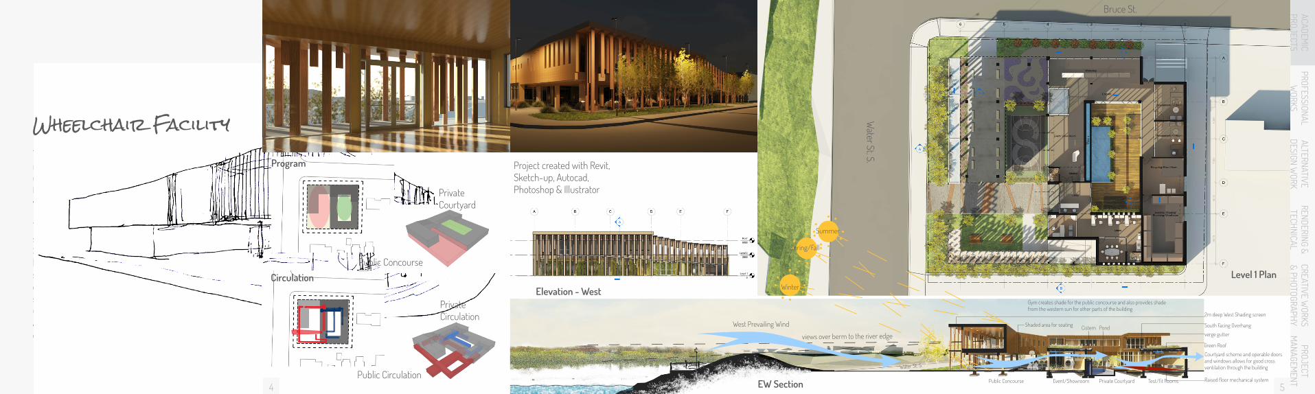
The nature of a wheelchair facility is one of rehabilitation and of learning. It should provide the user with comfortable environments suitable for the different stages of their adaptation to a new wheelchair.
The scheme of the project surrounds on two outdoor spaces: the public concourse fronting on Water Street and a private courtyard in the back enclosed by the building. The Public Concourse aims to be a space that creates a dialogue with the Cambridge community and allow users to interact with the local society. The private courtyard looks to provide the user with a peaceful regenerative environment and also a place where beginners or less confident users can practise using their chairs at their own pace.
Wheelchair Facility
Public Concourse
Program
Circulation
Public Circulation
PrivateCourtyard
PrivateCirculation
Grand River4
Elevation - West
Project created with Revit, Sketch-up, Autocad, Photoshop & Illustrator
ACADEMIC
PROJECTS
Level 1 Plan
Water St. S.
Bruce St.
EW Section
Gym creates shade for the public concourse and also provides shade from the western sun for other parts of the building
views over berm to the river edge
West Prevailing Wind Cistern PondShaded area for seating
Raised floor mechanical systemSupply
ReturnRadiant Cooling
Radiant Floor heating
Green Roof
Courtyard scheme and operable doors and windows allows for good cross ventilation through the building
verge gutter
South Facing Overhang
2m deep West Shading screen
Winter
Public Concourse
Water St. S.
Private CourtyardEvent/Showroom Test/fit Rooms
Spring/Fall
Summer
76
ACADEMIC
PROJECTSPROFESSIONAL
WORKS
PROF
ESSI
ONAL
W
ORKS
ALTERNATIVE DESIGN W
ORKALTE
RNAT
IVE
DESI
GN W
ORK
RENDERING & TECHNICAL
REND
ERIN
G &
TECH
NICA
LCREATIVE W
ORKS & PHOTOGRAPHYCR
EATI
VE W
ORKS
&
PHOT
OGRA
PHY
PROJECT M
ANAGEMENTPR
OJEC
T M
ANAG
EMEN
TAC
ADEM
IC
PROJ
ECTS
Spring/ Fall
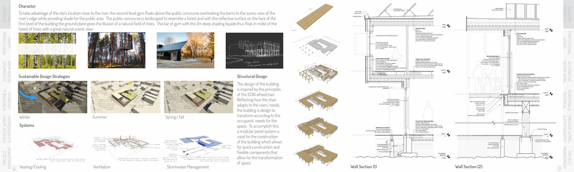
Sustainable Design Strategies
SummerWinter
Roof Top for Photovoltaic
Panel for energy collection
Green Roof - retains water and help manage water flow during rain
storms
Cistern and fountain store and redistribute water for irrigation
Spring/ Fall equinox sun angle ~ 46
2m deep west vertical shading
zone
Floating building creates shade for
outdoor public concourse
Fountain - promotes convection cooling
Over hangs to shade south sun and lower heat gain
operable openings to allow for ventilation
Summer Solstice sun angle ~ 70Low sun angle allow
heat gain in the winter even in over hanged places
South facing windows have
higher SHGC to allow for more
passive heating
Winter Solstice sun angle ~23
North-west prevailing winds
Systems
Heating/Cooling Ventilation Stormwater Management
Exhaust from workshop and gym washrooms
Landscape permeable
surface to slow down drainage of water off site
Supply Cistern
ReturnPondSupply low and
return high for displacement ventilation
Non-permeable surfaces sloped
to drain off site on to
street water system
Ventilation system works separate from Heat-ing and Cooling to enhance energy efficiency
Stormwater is collected from the roof off run by verge gutters into the cistern, water collected used for
grey water and pond in courtyardRadiant Panel Heating for a raised access floor system
which houses duct work for ventilation
The design of the building is inspired by the principles of the ICON wheelchair. Reflecting how the chair adapts to the users’ needs, the building is design to transform according to the occupants’ needs for the space. To accomplish this, a modular panel system is used for the construction of the building which allows for quick construction and flexible components that allow for the transformation of space.
Structural Design
Character
To take advantage of the site’s location close to the river, the second level gym floats above the public concourse overlooking the berm to the scenic view of the river’s edge while providing shade for the public area. The public concourse is landscaped to resemble a forest and with the reflective surface on the face of the first level of the building the ground plane gives the illusion of a natural field of trees. The bar of gym with the 2m deep shading façade thus float in midst of the forest of trees with a great natural scenic view.
ACADEMIC
PROJECTS
Level 1
0
FoundationBedrock
-1200
400x400 Glulam Column
20 mm Steel Base PlateBolt down to concrete base
200 mm Ø Sonotube
6 mm Steel Plate tosupport wood beam
for decking
Concrete Paving
Level 2
3500
Roof
7000
Cantilevered Floor Assembly :Calamine Steel Finish onPlanium/ Eurothem Modulo Radiante Raised Floor System: 600 x600 mm Panels with built in radiant piping set in a metal pan w/ expanded cellular concrete239 mm CLT ply7 Structural PanelAir/ Vapour barrier200 mm Extruded Polystyrene Insulation25 mm Oriented strand board20 mm Cross BattensWood Stripes
Roof Assembly :GravelFilter ClothWeather Seal Drainage Plane200 mm Polyisofoamcore Insulation sloped @ 2%155 mm Extruded Polystyrene InsulationAir/ Vapour Barrier (SOPRAVAP'R)239 mm CLT ply7 Structural Panel
Self-ballastingPhotovoltaic Panels
West-facing Glazing :Low-E triple glazing
in wood and aluminum frame(8 mm laminated safety glass +
14 mm cavity + 6 mm float glass +14 mm cavity + 6 mm float glass)
U = 0.7 W/m²K
400x600 Glulam Beam
10 mm metal platebolt column to beam
200 mm Precast Concrete Hollow Core Slab
Steel Angle
Wood Column(also part of shading structure)
20 mm PrecastConcrete Panel
Expansion Joint
Level 1
0
Level 2
3500
Roof
6000
FoundationBedrock
-1200
Typical Wall Assembly :25 mm Exterior vertical wood claddingHorizontal BattensVertical Battens (40 mm Air Space)8 mm Fibre-cement Sheeting131 mm Extruded Polystyrene InsulationAir/ Vapout Barrier (SOPRA Self adhesive membrane)169 mm CLT ply5 Structural Panel
Roof Assembly :GravelFilter ClothWeather Seal Drainage Plane75 mm Polyisofoamcore Insulation sloped @ 2%25 mm Oriented Strandboard172 mm Extruded Polystyrene InsulationAir/ Vapour Barrier (SOPRAVAP'R)239 mm CLT ply7 Structural Panel
Cladding Tiesw/ Thermal Break
Typical Floor Assembly :Calamine Steel Finish onModular Radiant Raised Floor System-600 x600 mm Panels with built in radiant pipingset in a metal pan w/ expanded cellular concrete239 mm CLT ply7 Structural Panel
South-facing Glazing:Low-E double glazing
in wood and aluminum frame(2x 4 mm float glass + 16mm cavity)
U = 1.1 W/m²K
Ground Floor Slab Assembly :Calamine Steel Finish onModular Radiant Raised Floor System-600 x600 mm Panels with built in radiant pipingset in a metal pan w/ expanded cellular concrete100 mm Concrete SlabAir/ Vapour Barrier65 mm Rigid Insulation
Filter Cloth
100 mm Ø Weeping Tile
180
200 mm Ø Sonotube
6 mm Steel Plate tosupport wood beam
for decking
Decking for Courtyard :40 mm Fir Wood Decking
38 x184 mm Wood Joists on steel hangers89 x 239 mm Wood Beams
Self BallastingPhotovoltaic Panels
Verge GutterGravel stop
Weather Board
South-facing Glazing:Low-E double glazingin wood and aluminum frame(2x 4 mm float glass + 16mm cavity)U = 1.1 W/m²K
Folding Wood Framed Sliding Window
Folding Wood Framed Sliding Doors(NanaWall)
Wall Section (2)Wall Section (1)

9
PROFESSIONAL W
ORKSALTERNATIVE DESIGN W
ORKRENDERING &
TECHNICALCREATIVE W
ORKS & PHOTOGRAPHY
PROJECT M
ANAGEMENT
8
Urban and residential design project for Parkdale area. Disconnected by the Gardiner and the railway tracks, Parkdale is separated from the park and waterfront which would provide amenities for the community. The projects works with the streets, considering them like veins in the body’s circulatory system, bringing vitality to and from the necessary amenities that creates a vibrant community.
Graphics made with AutoCAD, Sketchup, Photoshop & Illustrator
Parkdale Replanning
Figure Ground
Section Through Site
ACADEMIC
PROJECTSStreet Typology Unit Types
Side Streets2 lane traffic, 1 lane bike, 1 side parking
Service RoadsRoad and side walk
Bridge RoadsVariation of main street
with building only on one sideso only 1 side parking
Main StreetsMiddle Island, 2 lane traffic, 2 lane bike,
parking on both sides
Urban Plan
Upper Residential
Bachelor Units 1-2 Bdrms
Work lifestyle
Loft Units2 Bdrms
Live /work Life style
Family Units2-4 Bdrms
Family LifestyleAdditional private
exterior space
Mixed Family
Bachelor
Loft
Library
Community CenterTransit Center
Train Station
Public SquareArt GalleryStores
Farmer’s Market
Cinema
TheatreSchool
Parking Parking
Ground Hybrid Program
Underground Parking
Perspective of Public Square
Mixed Units1-4 Bdrms
Quick Turnoverstudent rental etc.

1110
PROFESSIONAL W
ORKSALTERNATIVE DESIGN W
ORKRENDERING &
TECHNICALCREATIVE W
ORKS & PHOTOGRAPHY
PROJECT M
ANAGEMENT
NatatoriumLocated in Christie Pits Park, the swimming facility is designed to provide a connection across the park in two directions. The building acts as a circulation corridor that takes users across and into the park as well as provide programs for fitness and recreation. The path taking users down into the park runs along the junction of the butterfly-winged glass roofs allowing the pedestrians to glimpse into the swimming pools underneath.
Perspective from Park
Longitudinal Section
Parti Concept/Physical Model
Street Elevation
ACADEMIC
PROJECTSStructural Axonometric
Plan
Pools Section
Park Elevation

1312
ACADEMIC
PROJECTSALTERNATIVE DESIGN W
ORKRENDERING &
TECHNICALCREATIVE W
ORKS & PHOTOGRAPHY
PROJECT M
ANAGEMENT
Drawings for a residential apartment tower in Guang Zhou, China. Drawings created with Autocad.
Working Drawings
Construction DrawingGeneral Plan
PROFESSIONAL W
ORKS
Building Core Detail
Bathroom and Kitchen Detail
Section AA Section BB

1514
ACADEMIC
PROJECTSALTERNATIVE DESIGN W
ORKRENDERING &
TECHNICALCREATIVE W
ORKS & PHOTOGRAPHY
PROJECT M
ANAGEMENT
GMDAT - drawings and rendering created for the design guideline book for GM International and GM Korea’s Chevorlet showrooms.
Nation Towers Abu Dhabi & Nation Riviera - model images and drawings created for design booklets and material boards for presentation to client. Multi-purpose tower and resort located in Abu Dhabi.
Design DevelopmentFurniture Plan
1:100
9232CONSTRUCTION DOCUMENTS - PROGRESS
Consultant
Sub ConsultantChk.A/EDrawn
Drawing Title
Scale Drawing No. Rev. No.
RFS No.Speciality Consultant
P. O. Box 27594
Tel : 971-2-4173000Abu Dhabi, U.A.E
web : www.keoic.comemail : [email protected]
Fax : 971-2-4173001
95 St. Clair Av W, Toronto
Tel : 416-9614111Ontario, Canada M4V 1N6
Fax : 416-9613176
Chk.QA/QC Project ManagerNo Chk'dDwnDateDescription
No Chk'dDwnDateDescription
Owner
Tel : 971-2-6525555P. O. Box 6481 Abu Dhabi
Fax : 971-2-6525600
Project Manager
Suite 1701, Shaikh Khalifa St,Butti Al Otaiba Building,
PO Box 5201, Abu Dhabi, UAE Project Principal
Copyright © 2010 by KEO International Consultants, WLLR:\5633p\WZMH_modified plans\_RFC-19\CAD UPLOADS\WZMH_Jan_17_11\Sheets\ASKD-471.8.dwg - ASK 3037 - 31 March 2011, 4:29 PM - vikkie
ASK 3037MARCH 29 , 2011
NOTE:DRAWINGS ARE THE INTENT OFARCHITECTURAL DESIGN ONLY AND THESTRUCTURAL, MECHANICAL, ELECTRICAL ANDARCHITECTURAL DETAILING TO BE BY KEO.FOR DESIGN REVIEW ONLY.NOT FOR CONSTRUCTION.
1:100
9232CONSTRUCTION DOCUMENTS - PROGRESS
Consultant
Sub ConsultantChk.A/EDrawn
Drawing Title
Scale Drawing No. Rev. No.
RFS No.Speciality Consultant
P. O. Box 27594
Tel : 971-2-4173000Abu Dhabi, U.A.E
web : www.keoic.comemail : [email protected]
Fax : 971-2-4173001
95 St. Clair Av W, Toronto
Tel : 416-9614111Ontario, Canada M4V 1N6
Fax : 416-9613176
Chk.QA/QC Project ManagerNo Chk'dDwnDateDescription
No Chk'dDwnDateDescription
Owner
Tel : 971-2-6525555P. O. Box 6481 Abu Dhabi
Fax : 971-2-6525600
Project Manager
Suite 1701, Shaikh Khalifa St,Butti Al Otaiba Building,
PO Box 5201, Abu Dhabi, UAE Project Principal
Copyright © 2010 by KEO International Consultants, WLLR:\5633p\WZMH_modified plans\_RFC-19\CAD UPLOADS\WZMH_Jan_17_11\Sheets\ASKD-290.15.dwg - ASK 3036 - 31 March 2011, 4:25 PM - vikkie
ASK 3036MARCH 29 , 2011
NOTE:DRAWINGS ARE THE INTENT OFARCHITECTURAL DESIGN ONLY AND THESTRUCTURAL, MECHANICAL, ELECTRICAL ANDARCHITECTURAL DETAILING TO BE BY KEO.FOR DESIGN REVIEW ONLY.NOT FOR CONSTRUCTION.
PROFESSIONAL W
ORKS
1:100
9232CONSTRUCTION DOCUMENTS - PROGRESS
Consultant
Sub ConsultantChk.A/EDrawn
Drawing Title
Scale Drawing No. Rev. No.
RFS No.Speciality Consultant
P. O. Box 27594
Tel : 971-2-4173000Abu Dhabi, U.A.E
web : www.keoic.comemail : [email protected]
Fax : 971-2-4173001
95 St. Clair Av W, Toronto
Tel : 416-9614111Ontario, Canada M4V 1N6
Fax : 416-9613176
Chk.QA/QC Project ManagerNo Chk'dDwnDateDescription
No Chk'dDwnDateDescription
Owner
Tel : 971-2-6525555P. O. Box 6481 Abu Dhabi
Fax : 971-2-6525600
Project Manager
Suite 1701, Shaikh Khalifa St,Butti Al Otaiba Building,
PO Box 5201, Abu Dhabi, UAE Project Principal
Copyright © 2010 by KEO International Consultants, WLLR:\5633p\WZMH_modified plans\_RFC-19\CAD UPLOADS\WZMH_Jan_17_11\Sheets\ASKD-471.8.dwg - ASK 3037 - 31 March 2011, 4:29 PM - vikkie
ASK 3037MARCH 29 , 2011
NOTE:DRAWINGS ARE THE INTENT OFARCHITECTURAL DESIGN ONLY AND THESTRUCTURAL, MECHANICAL, ELECTRICAL ANDARCHITECTURAL DETAILING TO BE BY KEO.FOR DESIGN REVIEW ONLY.NOT FOR CONSTRUCTION.
1:100
9232CONSTRUCTION DOCUMENTS - PROGRESS
Consultant
Sub ConsultantChk.A/EDrawn
Drawing Title
Scale Drawing No. Rev. No.
RFS No.Speciality Consultant
P. O. Box 27594
Tel : 971-2-4173000Abu Dhabi, U.A.E
web : www.keoic.comemail : [email protected]
Fax : 971-2-4173001
95 St. Clair Av W, Toronto
Tel : 416-9614111Ontario, Canada M4V 1N6
Fax : 416-9613176
Chk.QA/QC Project ManagerNo Chk'dDwnDateDescription
No Chk'dDwnDateDescription
Owner
Tel : 971-2-6525555P. O. Box 6481 Abu Dhabi
Fax : 971-2-6525600
Project Manager
Suite 1701, Shaikh Khalifa St,Butti Al Otaiba Building,
PO Box 5201, Abu Dhabi, UAE Project Principal
Copyright © 2010 by KEO International Consultants, WLLR:\5633p\WZMH_modified plans\_RFC-19\CAD UPLOADS\WZMH_Jan_17_11\Sheets\ASKD-290.15.dwg - ASK 3036 - 31 March 2011, 4:25 PM - vikkie
ASK 3036MARCH 29 , 2011
NOTE:DRAWINGS ARE THE INTENT OFARCHITECTURAL DESIGN ONLY AND THESTRUCTURAL, MECHANICAL, ELECTRICAL ANDARCHITECTURAL DETAILING TO BE BY KEO.FOR DESIGN REVIEW ONLY.NOT FOR CONSTRUCTION.
Elevation
Reflected Ceiling Plan Finish Plan

16
ACADEMIC
PROJECTSPROFESSIONAL
WORKS
RENDERING & TECHNICAL
CREATIVE WORKS
& PHOTOGRAPHYPROJECT
MANAGEM
ENT
9
BLOOM
Exploded Axonometric - Joint DetailTechnical Drawings
Origami Chair: a partner project to design a chair for an origami master. There is pattern to everything in the universe, be it the orthogonal lines of a grid or the complex forms of a flower. By exploiting the properties of geometry, and manipulating their forms in three dimensional space, a chair can be created that is comfortable, portable, and transformable. The design inspired by the geometric forms of the interlocking polyhedra, the organic forms of unfolding rose petals, and the shape, texture and configurations of the chinese lantern. The final chair was made with ½” plywood and paper fabric.
Bloom
ALTERNATIVE DESIGN W
ORK
CNC cut sheet for plywood frames and fabric cut sheet for folding
12
BLOOM
Cut sheetsConstruction Process
48”
59” 40”
All profiles are made from 1 sheet of 60”x60” plywood by arranging the profiles in a radial pattern in order to maximize the efficienct use of material.
All folds and angles for the fabric cutsheet are calculated based on the geometry of the structural profiles to ensure all sheets are identical.
17
1918
ACADEMIC
PROJECTSPROFESSIONAL
WORKS
RENDERING & TECHNICAL
CREATIVE WORKS
& PHOTOGRAPHYPROJECT
MANAGEM
ENT
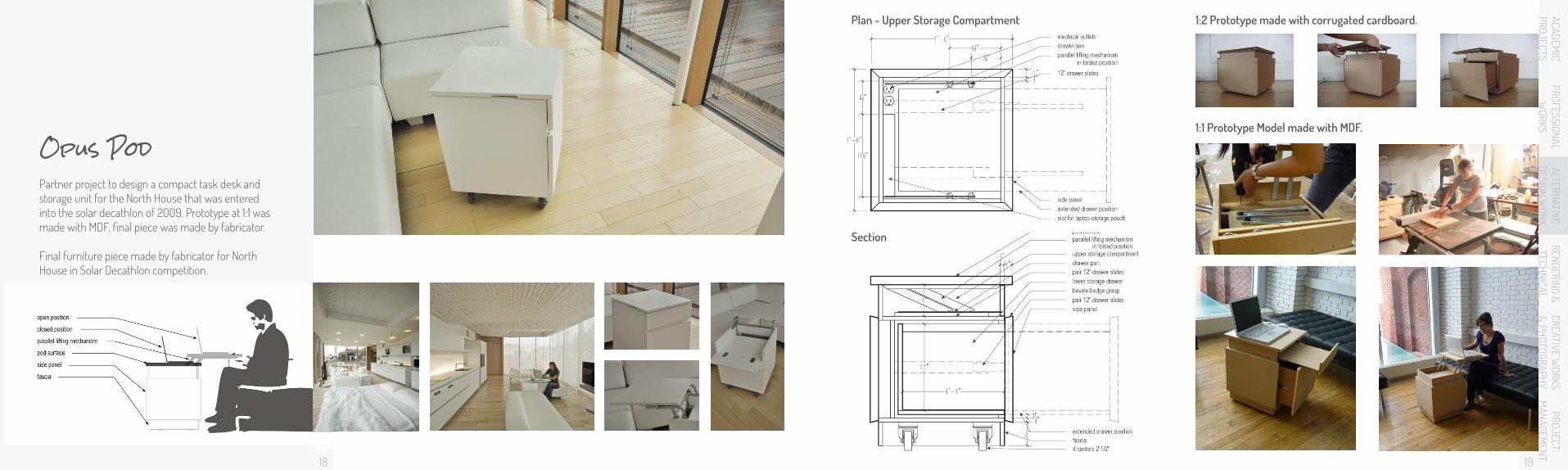
Partner project to design a compact task desk and storage unit for the North House that was entered into the solar decathlon of 2009. Prototype at 1:1 was made with MDF, final piece was made by fabricator.
Final furniture piece made by fabricator for North House in Solar Decathlon competition.
Opus Pod
ALTERNATIVE DESIGN W
ORK1:2 Prototype made with corrugated cardboard.
1:1 Prototype Model made with MDF.
Plan - Upper Storage Compartment
Section

20
ACADEMIC
PROJECTSPROFESSIONAL
WORKS
RENDERING & TECHNICAL
CREATIVE WORKS
& PHOTOGRAPHYPROJECT
MANAGEM
ENT
Group Landscape Installation Project for Uncommon Ground Exhibition 2012 in Cambridge ON. Created with mesh and foam strips.
Field Cushion
ALTERNATIVE DESIGN W
ORK
21

23
ACADEMIC
PROJECTSPROFESSIONAL
WORKS
ALTERNATIVE DESIGN W
ORKCREATIVE W
ORKS & PHOTOGRAPHY
PROJECT M
ANAGEMENT
Various rendered images produced with a combination of modeling and rendering software.
Physical models made from machine and laser-cut wood and acrylic.
Rendering & Modeling
22
RENDERING & TECHNICAL
Residential Townhouse Design3D Studio Max 2009
GM ShowroomSketchup ModelV-ray Rendering
Ratatouille Soup KitchenFormZ Render Zone, Adobe Photoshop

2524
ACADEMIC
PROJECTSPROFESSIONAL
WORKS
ALTERNATIVE DESIGN W
ORKCREATIVE W
ORKS & PHOTOGRAPHY
PROJECT M
ANAGEMENT
The Window Pavilion was design to challenge the the detailing of the building envelope around windows and doors. It served as a good case study for creating continuous air tight envelopes.
3D wall section of pavilion modeled and rendered in FormZ.
Plan and section done in AutoCAD and edited with Adobe Illustrator.
Grade
38x89mm Wood Stud
Sill GasketSill Plate
FlashingGutter
Prefinished Fascia
25mm Fibrous Expansion Material
Undisturbed soil
Disturbed soilFilter Cloth100mm diameter Weeping TileFlashing
Key
200x500mm Concrete Footing
13mm Hardwood Flooring20mm Plywood
Exploded 3D Wall Section
Windows Pavilion
RENDERING & TECHNICAL
0m 1m 2m 3m
0m 1m 2m 3m0m 1m 2m
12mm Drainage MatVapour Barrier12mm Parging300mm Concrete Foundation Wall25mm Airspace38x89 wood studs at 400 o.c. with Batt InsulationVapour Barrier13mm Gypsum Board
13mm PlywoodVapour Barrier
38x286mm Header100mm Batt Insulation38x286mm Floor Joists
at 400mm o.c.
100mm Concrete Floor Slab with 150x150mm Wire FabricVapour Barrier50mm Rigid Insulation150mm Clean Gravel
Rainscreen Window
12mm diameter Anchor Bolt
13mm Gypsum BoardVapour Barrier
38x89mm Wood Studs with Batt Insulation
13mm Plywood13mm Stucco Finish
Holes in I-Joist for Cross Ventilation between Joists
57mm Stone Veneer35mm AirspaceAdjustable Stone Veneer TiesBuilding Paper100mm Reinforced Concrete Block13mm Plywood38x89 Wood Studs at 600 o.c. with Batt Insulation13mm Gypsum Board
Standing Seam Metal RoofingBuilding PaperRoof SheathingWood I-Joist at 400 o.c. with 286mm of Batt InsulationVapour Barrier13mm Gypsum Board Ceiling
Gaskets
Construction PlanWall Section
Concrete Sill
0m 1m 2m

2726
ACADEMIC
PROJECTSPROFESSIONAL
WORKS
ALTERNATIVE DESIGN W
ORKCREATIVE W
ORKS & PHOTOGRAPHY
PROJECT M
ANAGEMENT
Cantilever PavilionDesign & Form - Inspired by the canopy created by trees, the cantilever allows for the creation of a light and breezy structure. The steel allows it to be complex but simple, while still maintaining its flexibility.
Site - Located in Cambridge, Ontario, the pavilion will be located on the banks of the Churchill Park Pond, framed by the swaying willow trees.
Partners project done in April 2008. Models were created with FormZ v6.5.4 and montages are done with Photoshop. InDesign was used for the layout.
Front Elevation Side Elevation
RENDERING & TECHNICAL
BASE DETAIL1 HSS 102 – 8 mm thick2 Steel Seat Plates3 Structural Tees – Cut from W Shapes4 Custom Steel Collar Joint – 10 mm thick Bolts5 Base Connection – Welded from HSS 114, and 30 mm Shaped Steel6 High Strength Bolts and Nuts with 5 mm thick Washers7 Steel Base Plate with Pre-Cut Holes 8 Concrete Foundation – 600 x 600 x 100 mmTRANSLUCENT SAIL DETAIL9 HSS 102 with Welded Flange10 Threaded Rod – 20 mm Diameter11 Carabiner Clip12 Branched Rod Connector13 Cable Connectors14 Laminated Fine Weave Fabric with PTFE FilmRIB DETAIL15 HSS 102 – 8 mm thick16 Welded Collar Joint17 Tension Cables18 HSS 102 – 8 mm thick with Welded Flange19 Tapered Collar Joint20 HSS 60 – 4.8 mm STRUCTURAL ARC DETAIL21 HSS 102 – 8 mm thick22 Connection Welded from HSS 114 – 4.8 mm Thick, and Shaped 30 mm thick Plates
1
2
3
7
8
6
4
5
22
21
2019
18
17
1615
11 129
10
14
13
Structural Arcs
Translucent Fabric Sails
Ribs
Connection Details
Benches
Base Connections

2928
ACADEMIC
PROJECTSPROFESSIONAL
WORKS
ALTERNATIVE DESIGN W
ORKRENDERING &
TECHNICALPROJECT
MANAGEM
ENT
ARt
HSBC commissioned painting. Acrylic on 22” X 30” canvas. My class was asked to create paintings for their new office. The theme for these paintings were multiculturalism.
Illustration of the Notre Dame in Paris. Pen and ink on 16” X 20” canvas.
CREATIVE WORKS
& PHOTOGRAPHY
Chinese tradition dress made with silk and painted with watercolour.
Impressionist styled painting of a backyard garden. Acrylic on 16” X 20” canvas.
Origami roses made from japanese paper.
Colour marker and fineliner drawing on Postcard for Night of Postcards Project

3130
ACADEMIC
PROJECTSPROFESSIONAL
WORKS
ALTERNATIVE DESIGN W
ORKRENDERING &
TECHNICALPROJECT
MANAGEM
ENT
The camera is the lens through which I look at the world in a different perspective — one that is unusual or framed for a particular effect. Following is a collection of photographs from travels to various destinations and places I’ve lived.
Photography
CREATIVE WORKS
& PHOTOGRAPHY

ACADEMIC
PROJECTSPROFESSIONAL
WORKS
ALTERNATIVE DESIGN W
ORKRENDERING &
TECHNICALCREATIVE W
ORKS & PHOTOGRAPHY
The No Small Plans exhibition that was open from July 5th to August 31st, 2014 was hosted in the Canadian Clay and Glass Gallery in Waterloo. The exhibit celebrated the rich concentration of design culture in the Region by featuring eight Governor General Award-winning buildings built in Waterloo Region. I co-curated the exhibition with professor Rick Haldenby and curator Esther E. Shipman, as well as assisted with the festival of exhibition and related events involved in the Building Waterloo Region program.
Building Waterloo Region
32
PROJECT M
ANAGEMENT
33

35
ACADEMIC
PROJECTSPROFESSIONAL
WORKS
ALTERNATIVE DESIGN W
ORKRENDERING &
TECHNICALCREATIVE W
ORKS & PHOTOGRAPHY
BRIDGE is a student initiative at the Waterloo School of Architecture. It is a collective that supports and inspires student projects, providing opportunities for students to experiment, collaborate, and communicate all aspects of architectural design. As one of the Executive Directors, I actively coordinates cultural ventures in Cambridge and Waterloo to create a dynamic interaction between the students and the community.
BRIDGE
34
PROJECT M
ANAGEMENT

Cel l : 4 16 . 875 .0886
E-mai l : chen .v ikk ie@gmai l . comwww.v ikk i echen .com
Thank you