· web viewpage 5 & 6find out about the differences between series and parallel circuits...
TRANSCRIPT

✗
Electronics Circuit Trainer
Safe, Educational and Fun with Solderless Connections!
Students ManualEasy-To-Read Lab-Style Manual for the Student
Burglar AlarmEver wondered how a Burglar Alarm is activated then reset. We show you how.
Page 8
Wet & DryDiscover what happens when you place your probe in water, stand back and see the results.
Page 9
Darlington PairCheck out the difference an extra transistor can make to this otherwise modest temperature
Page 10
This kit is almost like instant electronics because you can begin building your first circuit right now. That’s right no soldering and no cutting of wires required!Before you begin, make sure you have a PP3 9 volt battery or 9 volt unregulated power supply. These are not supplied in the kit but will be given to you by your teacher. Every activity uses them. Place the batteries in the battery holder. Don’t ever leave the battery or power supply connected to the kit when you are not using the kit.
The Electronic Circuit Trainer consists of a board covered with electronic parts and ‘jump leads’ you will use to connect those
parts. In addition to the electronic parts on the board you will see different coloured sockets (red, black, white, green and blue). These sockets are the starting point to starting right now. Simply follow the circuit diagram for each activity and plug in the leads to connect the correct parts (colour code chart below for identifying the correct resistors) to each other, making sure you take note of the useful information found under the ‘Action!’ section of each activity. In the same section you will also learn about the key electronic component being used in the ‘activity’.
HAVE FUN!
Before you start…
Parts List
Series & ParallelFind out about the differences between series and parallel circuits and what happens to two
Page 3 & 4
Light & DarkSee what happens when light starts to dim and control what happens when it does.
Page 5 & 6
Hot & ColdFrost Alarm or Heat Sensor you decide just make sure you know which before you place in the fridge.
Page 7
✗✗
SPST Standard Toggle Switch
Red Button Chrome PTM Switch
6V Electronic Buzzer
50K Precision NTC Thermistor
10K Linear 248-7 Potentiometer
100K Linear P260P Potentiometer
Bulb Holder MES Batten Black
R10 MES Tubular 10mm 6V 183mA
BC108 NPN GP Transistor
BFY50 TRAN NPN 35V 1A TO39
NORPS12 Light Dependent Resistor
C106D 400V 4A Thyrister
¼ W Carbon Film Resistor 1M
¼ W Carbon Film Resistor 2.2K Ohms
¼ W Carbon Film Resistor 470

2
If two bulbs are in series then you have to go through both of them to get from one terminal of the battery to the other. In other words there is only one conducting path.If two bulbs are in series then there are two problems1. Both bulbs are dimmer than they would be by themselves2. You can't turn one bulb off without turning both offThe bulbs are dim for two reasons:1.The current going through them is smaller because two bulbs in series have a higher resistance than a single bulb.2.Each charge only gives up some of its energy in each bulb, i.e. the potential difference across each bulb
is smallerIf the bulbs are the same then each charge will give up half its energy.Remember there is no 'first' bulb. The charges are already there and they flow everywhere at the same time. The current is the same all the way round a series circuit.Power depends on both voltage and current. With two bulbs in series you halve the voltage and roughly halve the current so the power dissipated in each bulb, and hence the brightness, is roughly a quarter what it would be if the bulb were connected alone.
NOW YOU TRY...
Circuit Activity No.1Lamps in Series
Action!In this task you need to use the connecting leads to create a simple series circuit using the SPST Switch and the 2 two lamps connected to your power supply. The good news is these lamps have no polarity so you cannot connect them the wrong way around.
See what happens when the switch the circuit on…you will see that bulbs in parallel are equally bright because they're always connected across the same voltage. Lamps emit light when an electric current passes through them. Both the lamps provided have a thin wire filament, which becomes very hot and glows brightly when a current passes through it.

Particularly in winter there is often a need for a warning device that would sound an alarm or a flashing light when the temperature falls below a recommended level.
How the Circuit Works
The temperature sensor is the Thermistor. This is a type of variable resistor whose resistance increases as it becomes cold. When this happens the current flows to turn on the transistor. When the transistor is on the buzzer will be on. The potentiometer allows you to set the sensitivity of the circuit.
You will notice the temperature-sensing circuit is divided into the three main building blocks Input, Process and Output. Look at the circuit diagram below and write down which of the components relate to which building block.More about Thermistors
A thermistor is an input transducer (sensor), which converts temperature (heat) to resistance. Almost all thermistors have a negative temperature coefficient (NTC) which means their resistance decreases as their temperature increases. It is possible to make thermistors with a positive temperature coefficient (resistance increases as temperature increases) but these are rarely used.
On the Electronic Circuit Trainer you will find a 20K Thermistor at 25, suppliers usually specify thermistors by their resistance at 25°C (room temperature). Thermistors take several seconds to respond to a sudden temperature change, small thermistors respond more rapidly.
NOW YOU TRY…
3
If two bulbs are in parallel then the current drawn from the battery increases. The current drawn would continue to increase if more components are connected in parallelThere are two advantages of connecting bulbs in parallel.1.They all get the full battery voltage so they're all bright2.They're all in their own conducting loop so you can turn one bulb off without affecting the others
When bulbs are connected in parallel they must have the same voltage across them. You can treat them as if they're each in their own circuit (which if you treat circuit as meaning
loop, they are).If the bulbs are different then the lower resistance one will draw the bigger current and be brighter. This is just Ohm's law: small resistance means big current.The battery of a parallel circuit doesn't 'know' what's connected to it. All it feels is an overall resistance (or if you like an overall demand for current). The resistance that the battery feels is called the effective resistance of the circuit.If you were to add more and more components in parallel the current drawn from the supply gets bigger and bigger. If the current gets bigger then the resistance must be getting smaller. So by adding resistances you actually decrease the effective resistance.It doesn't matter how
Circuit Activity No.2Lamps in Parallel
Action!In this task you need to use the connecting leads to create a simple parallel circuit using the SPST Switch and the two lamps connected to your power supply. The good news is these lamps have no polarity so you cannot connect them the wrong way around.
See what happens when the switch the circuit on…. it shows that bulbs in parallel are equally bright because they're always connected across the same voltage.
In these lamps the filament is made from a metal with a high melting point such as tungsten and it is usually wound into a small coil.
Often used in children’s Night Lights, this circuit offers the ultimate solution of bring light to a room when it goes dark!The LDR (Light Dependent Resistor) is the sensor and its resistance increases with darkness. The potentiometer allows you to set how dark it will be before the lap goes on.The transistor is a high-speed switch that turns on when a voltage of 0.6 – 0.7V is present at its base leg.The LED (Light Emitting Diode) will only come on if the transistor is on. Circuits are divided into three main building blocks. These are INPUT, PROCESS and OUTPUT.This circuit can be divided into these three main building blocks. This is also
evident on the Electronic Circuit Trainer. Have a look and write down what they are.How the Circuit WorksWhen you close the on/off switch (SPST) during the day the current flows from the battery down through the potentiometer to the LDR. As light is hitting the LDR it will have a very low resistance and act as a conductor. Current flows through it back to the battery.In the dark, the LDR will have a very high resistance. This means the current cannot pass through it and must find another route back to the battery. It flows through the 2.2K resistor to the base of the transistor. If the voltage is greater than 0.6V the current will flow into the transistor, switching it on.
Circuit Activity No.3Dark Activated Circuit
Action!In this task you need to use the connecting leads to build a Dark Activated Circuit.
Something you should remember about LEDs is that they must be connected the correct way round. You will notice on the Electronic Circuit Trainer it is labeled the circuit symbol and is also shown above. The circuit symbol is pointing the same way the LED on the trainer so from this you should be able to deduce the a or + for anode is on the left and the and k or - for cathode (yes, it really is k, not c, for cathode!) is on the right.
For future soldering projects, the cathode is the short lead and there may be a slight flat on the body of round LEDs.
This circuit works the opposite way to the dark-activated circuit in that it is designed to come on when light hits the LDR. An automatic daylight circuit would be used in a security box.In this circuit the LDR would be above the 10K PotentiometerWhen the switch (SPST) is in the on position the LED (or alarm) would sound if the box was opened, allowing light to shine on the LDR.
How the Circuit WorksIf the LDR is placed in the dark (this can be simulated by placing your hand over the LDR), it will have a high resistance. In this state the current cannot through it. The circuit remains off.
When light hits the LDR its resistance falls so that the voltage at the mid-point of the potential divider rises. When this reaches 0.6 volts, current will flow to the transistor. When the transistor is on the current can pass through it and return to the battery. As the transistor is now on, the current can now flow through the output part of the circuit. When this happens the LED will light.
NOW YOU TRY…
Circuit Activity No.4Light Activated Circuit
Action!In this task you need to use the connecting leads to build a Light Activated Circuit.
Something you should remember about Light Dependent Resistors is that an LDR may be connected either way round but don’t forget to connect the transistor the correct way otherwise you will damage it when battery is connected!
The newer standard LDR is the NORP12, and is the type used on the Electronic Trainer Board. Typical resistance for LDRs is:
Darkness: maximum resistance, about 1M . Very bright light: minimum resistance, about 100 .
.
Circuit Activity No.5Temperature Sensing Circuit
Action!In this task you need to use the connecting leads to build a Temperature Sensing Circuit.
Before you start building the circuit on the Electronic Trainer Board, there are a few things you should be aware of about thermistors:
1. A thermistor may be connected either way round
2. No special precautions are required when soldering.
Yes it’s that easy so what’s stopping you!
Bonus Activity!
Draw a potential divider that could be used as a sensor circuit in a fire alarm, how would it differ from the circuit you have built.

4
Homes are at constant risk from burglars. What better solution than to build a burglar alarm that is activated when contact is made for example between a door and its frame? In the home situation, you might use a device known as a Magnetic Reed Switch. The reed switch would be fixed to the side of a box of some type and the magnet would be fixed to the edge of the door. A separate Key Switch would be turned on to “activate’ the Burglar Alarm. If the door were opened the alarm would sound. The key holder (of the Key Switch) would reset the alarm.
So on the Electronic Circuit Trainer we have the SPST Switch that plays the part of the Key Switch and the PTB Switch, which plays the part of the Magnetic Reed Switch.
When the SPST Switch is closed power goes to the circuit.The PTB is used as the sensor. The Thyristor is a latching device. It comes on when small voltage is present at the gate leg (g). It can only be turned off again by cutting the power to the anode leg (a). The buzzer will sound when the thyristor is on.
How the Circuit WorksWhen the SPST Switch is turned to the on position the alarm is set. The current cannot flow past the PTB Switch.
The alarm is activated by the intruder (in this case by you momentarily pressing the PTB Switch).At this point the current will flow down the gate leg of the thyristor (g) and cause it to switch on. The current is now able to return to the battery. The thyristor is a latching
Circuit Activity No.6Burglar Alarm
Action!In this task you need to use the connecting leads to build a Burglar Alarm.
Something you should remember about thyristors:
As with transistors (and FETs), thyristors have three legs. However for a thyristor the legs are called the cathode (c), anode (a) and gate (g).
When connecting the thyristor make sure you connect the right legs to the correct part of the circuit, it will not work unless you do and make cause damage to the thyristor when power is connected.
The thyristor may also be referred to as a flip-flop but it is more correctly known as a bistable (previously referred to as a latch)
.

5
Moisture Sensors use a circuit that you have seen before, that is the by now familiar potential divider. If one of the resistors in a potential divider is replaced with some type of analogue sensor, it can be used to provide a voltage signal at the output that varies with the intensity of the thing (i.e. light, sound temperature) being measured.So if you change one of the resistors in a potential divider with moisture probes, in this case no more than a couple of jack plugs on the end of leads but more commonly copper PCB shaped like a flat stick, an output voltage can be produced. This varies with moisture level in soil or the presence of water such as an alarm that indicates when water in a bath has
reached its required level.Water, as you know, is a conductor of electricity and will allow current to flow when both ends of the probe are immersed in the same water. Equally, when placed in soil which is very dry and no moisture is present then there exists no ability to allow current to conduct and a very high resistance exists much like an insulating material. As moisture increases then the resistance between the probes decreases and allows current to flow.
How the Circuit WorksWhen the SPST switch is placed to the ON position power goes to the circuit. When the probes are set in water approx. 25mm apart, the water acts as a conductor and current flows between them. When this happens a small amount of
Circuit Activity No.7Moisture Sensing Circuit
Action!In this task you need to use the connecting leads to build a Moisture Sensing Circuit.
In this action, we shall look at the variable resistor.
Variable resistors consist of a resistance track with connections at both ends and a wiper, which moves along the track as you turn the spindle. The track is typically made from carbon. The track is usually rotary.
Although variable resistors tend to be labelled in catalogues as potentiometersthey may be used as a rheostat with two connections (the wiper and just one end of the track) or as a potentiometer with all three connections in use. On the Electronic Circuit Trainer we are using the potentiometer as a rheostat.
.
6
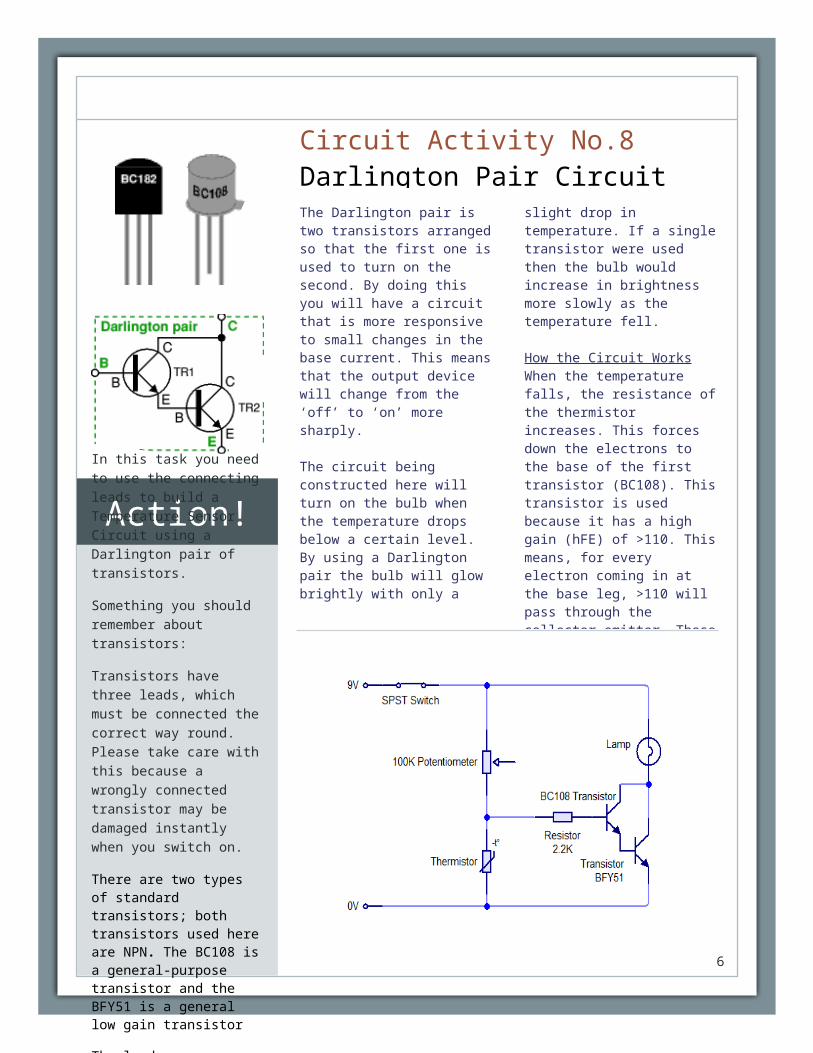
The Darlington pair is two transistors arranged so that the first one is used to turn on the second. By doing this you will have a circuit that is more responsive to small changes in the base current. This means that the output device will change from the ‘off’ to ‘on’ more sharply.
The circuit being constructed here will turn on the bulb when the temperature drops below a certain level. By using a Darlington pair the bulb will glow brightly with only a slight drop in temperature. If a single transistor were used then the bulb would increase in brightness more slowly as the temperature fell.
How the Circuit Works
When the temperature falls, the resistance of the thermistor increases. This forces down the electrons to the base of the first transistor (BC108). This transistor is used because it has a high gain (hFE) of >110. This means, for every electron coming in at the base leg, >110 will pass through the collector-emitter. These 110 electrons are then presented to the base leg of the second transistor (BFY51). This has a gain 40. You now have a total minimum gain of 110 x 40 = 4400.A gain of 4400 will enable the small flow of electrons ( current) coming in at the base of the BC108 to be amplified twice causing a large flow of electrons through the BFY51. It is this large flow that makes the
Circuit Activity No.8Darlington Pair Circuit
Action!In this task you need to use the connecting leads to build a Temperature Sensor Circuit using a Darlington pair of transistors.
Something you should remember about transistors:
Transistors have three leads, which must be connected the correct way round. Please take care with this because a wrongly connected transistor may be damaged instantly when you switch on.
There are two types of standard transistors; both transistors used here are NPN. The BC108 is a general-purpose transistor and the BFY51 is a general low gain transistor
The leads are labelled base (B), collector (C) and emitter (E).
.

Safety Tips1. Chocking Hazard! This product contains small parts. Not meant for children less than ten years of age. Use with adult supervision 2. This product contains glass light bulbs. Misuse may cause it to break, resulting in sharp pieces that could result in a cut. Use with caution. 3. Please use a standard PP3 9 volt battery or a 9-volt unregulated/regulated power supply with this product. 4. Do not connect positive and negative poles directly. 5. Always connect the battery or power supply after completion of building the circuit otherwise you may damage the parts
Hansen Enterprise LimitedDesign & Technology EducationBrighton UniversityFalmerBrightonBN1 9PH
The activities in this kit are designed to comply with BSI Standard Electric Toys, Safety BS EN 62115:2005