· web viewabuja, nigeria , 20-31-may 2013 workshop exercises sheet exercise 1 start-up with...
TRANSCRIPT

ITU Regional Workshop on SMS4DC for
English Speaking countries in Africa,
Abuja, Nigeria , 20-31-May 2013
Workshop Exercises Sheet
Page 1 of 44

Exercise 1
Start-up with SMS4DC
Step 1: Set up SMS4DC system
Step 2: Launch the SMS4DC software using username and password of SMS4DC.
Step 3: Choose Country from list(ex NIG)
Step 4:Using IDWM Status Bar draw Country/Region and Coastal Zones
Step 4: Launch the DEM view using toolbar push button.
Step 6: Go to Tools ColorMap and select color.
Step 7: Go to Vectors Draw country border.
Step 8: Go to Database Users and then create new account.
Step 9: Establish station “Test 1”using and set frequency to 150MHz and antenna
height above ground level (AGL)to 40m, and power to 30w.
Step 10: View SMS4DC installed folders
C:\BDT_Soft\SMS4DC
Page 2 of 44

Exercise 2
SMS4DC Antenna Editor
Step 1: Launch the SMS4DC software.
Step 2: Launch the DEM view using toolbar push button
Step 3: Go to tools select antenna editor
Step 4:load antenna from antenna libraries
C:\BDT_Soft\SMS4DC\Antenna
Step5: View E-plane, H-plane, and 3D
Step6: Make a suitable modification to the antenna radiation pattern by editing
(degrees/attenuation) or Graphically by mouse click on wanted points on the E-Plane
or H-Plane display.
Step7:Save the modified pattern in antenna libraries.
C:\BDT_Soft\SMS4DC\Antenna
Page 3 of 44

Exercise 3
SMS4DC Technical parameters
Step 1: Launch the SMS4DC software.
Step 2: Launch the DEM view using toolbar push button
Step 3: Establish FX station “Test 2”using and set the frequency to 150 MHz
and antenna height above ground level to 40m, and set power to 30w .
Step 4: Choose antenna “the antenna which you define in the exercise 2” and check the
antenna pattern.
Step 5: Select Calculation from the top menu and choose “Effective height”, then select
station “Test2”.
Step 6: Right-click on the effective height figure and select “save effective height
(Database)”, Then close the effective height window.
Step 5: Select draw line from tool bar and connect between “TEST 1” to “TEST
2”, then select calculation menu from toolbar and then calculate: Azimuth angle ,
Elevation angle , and distance.
Step 6: Select draw line from tool bar and connect between “TEST 2” to “TEST
1”, then select calculation menu from toolbar and then calculate: Azimuth angle ,
Elevation angle , and distance.
Step 7: Go to Database Licensing Anonymon station and “TEST 1” and
“TEST 2” then go to the level of “antenna” the press modify and then fill the Azimuth
and elevation which you obtain from step 5 and 6.
Step 8: Go to Database Licensing Anonymon station and “TEST 1” and
“TEST 2” then go to the level of ”frequency” then press add receiver then select
“point” , then add “TEST 1” and “TEST 2” as receiver to each other.
Step 9: Go to Tools Google Earth Export/Display links and the select
“TEST 1” and “TEST 2.
Page 4 of 44

Exercise 4
Frequency Allocation
Step 1: Launch the SMS4DC software.
Step 2: Launch the DEM view using toolbar push button.
Step 3: Open the menu “Frequency Allocation” and select “Draw Chart”.
Step 4: Set the “Region” field to “Region 1”, and set the frequency from 800 to 2400
MHz .
Step 5: left-click on a colored patch to show its characteristics
Step 6: From “Edit” menu select “Plan”, then create a new allocation by clicking on the
push button then push save button.
Step 7: From “Edit” menu select “Footnote” to Show the existing footnotes, and then
click on the push button to add a new footnote then push save button.
Page 5 of 44

Exercise 5
National Frequency Allocation Table
Step 1: Launch the SMS4DC software.
Step 2: Launch the DEM view using toolbar push button.
Step 3: Open the menu “Frequency Allocation” and select “Draw Chart”.
Step 4: Set the “Region” field to “National”,
Step 5: Go to edit and select plan service table and then press add new record
Step 7: Define service code , primary service name , secondary service name, and
color and then press save bottom and close this window
Step 8: Go to edit and select plan and then press add record
Step 9: Add several new records from UAE NAT , primary services, secondary
services, service footnotes , and then close the window
Step 4: Go to edit and select footnote and then define your Footnotes
Step 4: Switch to the main window and then check the modifications
Page 6 of 44

Exercise 6
Frequency Arrangement FM
Step 1: Launch the SMS4DC software.
Step 2: Launch the DEM view using toolbar push button.
Step 3: Open the menu “Frequency Allocation” and select “Frequency Arrangement”.
Step 4: Create a new Frequency Arrangement by using push button.
Step 5: Set Region to Region 1, Service priority to Primary, Service to Broadcasting.
Step 6: Set Type of frequency to Uniform, Channel spacing 0.3MHz, Reference
frequency Fo= 87.6MHz, First channel 0, last channel 67, then click on the push
button to save the new arrangement.
Step 7: Click on the push button to view the new arrangement report.
Page 7 of 44
Exercise 7
Frequency Arrangement 900MHz
Step 1: Launch the SMS4DC software.
Step 2: Launch the DEM view using toolbar push button.
Step 3: Open the menu “Frequency Allocation” and select “Frequency Arrangement”.
Step 4: Create a new Frequency Arrangement by using push button.
Step 5: Set Region to Region 1, Service priority to Primary, Service to Land mobile.
Step 6: Set Type of frequency to Homogeneous, Channel spacing 0.2MHz, Reference
frequency Fo= 900MHz, foff=0,f’off=45, First channel 1, last channel 125, then click on
the push button to save the new arrangement.
Step 7: Click on the push button to view the new arrangement report.
Page 8 of 44

Exercise 8
Frequency Arrangement UMTS
Step 1: Launch the SMS4DC software.
Step 2: Launch the DEM view using toolbar push button.
Step 3: Open the menu “Frequency Allocation” and select “Frequency Arrangement”.
Step 4: Create a new Frequency Arrangement by using push button.
Step 5: Set Region to Region 1, Service priority to Primary, Service to Land mobile.
Step 6: Set Type of frequency to Homogeneous, Channel spacing 5MHz, Reference
frequency Fo= 2000MHz, foff=-100 ,f’off=110 MHz, First channel 1, last channel 12,
then click on the push button to save the new arrangement.
Step 7: Click on the push button to view the new arrangement report.
Page 9 of 44

Exercise 9
Frequency Arrangement UMTS
Step 1: Launch the SMS4DC software.
Step 2: Launch the DEM view using toolbar push button.
Step 3: Open the menu “Frequency Allocation” and select “Frequency Arrangement”.
Step 4: Create a new Frequency Arrangement by using push button.
Step 5: Set Region to Region 1, Service priority to Primary, Service to Land mobile.
Step 6: Set Type of frequency to Homogeneous, Channel spacing 6MHz, Reference
frequency Fo= 1900MHz, foff=0,f’off=30MHz , First channel 1, last channel 10, then
click on the push button to save the new arrangement.
Step 7: Click on the push button to view the new arrangement report.
Page 10 of 44

Exercise 10
Frequency Assignment
Step 1: Launch the SMS4DC software.
Step 2: Launch the DEM view using toolbar push button.
Step 3: Open the menu “Frequency Allocation” and select “Frequency Assignment” .
Step 4: Set low freq=87 and high Freq=108
Step 5: Select “Test 1” station.
Step 6: Set Freq min= 87 and Freq max=108 and search radius to 200 Km and push
OK.
Step 7: Find a frequency channel without interference and double-click on it to assign
to station Test1.
Page 11 of 44
Exercise 11
Creating licenses
Step 1: Launch the SMS4DC software.
Step 2: Launch the DEM view using toolbar push button.
Step 3: Establish BC station “BCTest1”using and set the frequency to 100 MHz
and antenna height above ground level to 50m.
Step 4: Choose antenna “DEFAULT” and check the antenna pattern.
Step 5: Select Calculation from the top menu and choose “Effective height”, then select
station “BCTest1”.
Step 6: Right-click on the effective height figure and select “save effective height
(Database)”, Then close the effective height window.
Step 7: Open the administrative part from “Database-> Licensing”.
Step 8: Select “anonymous Station” and find station “BCTest1”.
Step 9: Right-click on administrative data and select “New Owner”, then complete
Owner information fields.
Step 10: Go to “Active Licenses” and find the crated owner.
Step 11: Right-click on the Owner’s name and select “New License”, then complete
License information fields.
Step12: Right-click on the License’s name and select “Move Anonymous Station”, then
select station “BCTest1”.
Step13: Select “Billing History” to show the billing information of the owner.
Step 14: Right-click on the “Billing History” and add a new payment to the owner.
Page 12 of 44

Exercise 12
Effective Height
Step 1: open the administrative part from “Database-> licensing”.
Step 2: Select “Active Licenses” and find station BCTest1, and select Provision=
Article11 and Notice type=T01.
Step 3: Open Equipment Information Table of Station BCTest1.
Step 4: Push the “Modify” Button.
Step 5: Change the field “FM Transmission code” to 2 and push ENTER then fill fields
“Equipment Name” and “Power type”.
Step 6: Push the “Save” Button.
Step 7: Close Administrative dialog box.
Step8: Open The “Database” Menu and select “Station in Desktop”.
Step 9: Select the record of station (BCTest1).
Step 10: Push OK button to display station on map.
Step 11: Open the menu “Calculations” and select “Effective Height” item.
Step 12: Select the record BCTEST1.
Step 13: Open the menu “Tools” and select “Background” item.
Step 14: Open the menu “Tools” and select “Save Effective Height (database)” item.
Page 13 of 44

Exercise 13
Propagation Models
Step1: Launch the SMS4DC software.
Step 2: Launch the DEM view using toolbar push button.
Step3: Open the “Database’’ menu and select ”Station in Desktop’’.
Step4: Select the record of station(BCTEST1).
Step5: Push OK button to display station on map.
Step6: Draw a Box around BCTEST1 station by using toolbar push button
Step7: Open the menu “propagation Models” and select “P.1546” item and select Area.
Step8: Select the record BCTEST1.
Step9: Set parameters and push OK then save results .
Step10: Open the menu “Tools” and select “contour value” item and then set threshold
value and push OK then save results.
Step11: Open the menu “Tools” again and select “remove contour from display”
Step12: Open the menu “Tools” again and select “coverage Area”.
Step13: Open the menu “window” and select “Main Desktop”.
Step14: Open the menu” Propagation Models” and select “Overlay” then select Area
calculation(P1546).
Step 15: Go to step 7 and select other point to Area Propagation models and repeat
steps 8 -14.
Step 16: create another station near to the ‘BCTEST1’ station with freq=100 MHZ with
the name of ‘BCTEST2’.
Step 17: Draw a Box around ‘BCTEST1’ and ‘BCTEST2’ stations by using
toolbar push button.
Step 18: Open the menu ” Propagation Models” and select “P.1546” item and then
select Network processor and then Maximum field strength .
Step 19: Select ‘BCTEST1’ and ‘BCTEST2’ stations from list of stations ,perform
calculation and overlay the results on the DEM map.
Page 14 of 44

Step 20: Open the menu ” Propagation Models” and select “P.1546” item and then
select Network processor and then Best server.
Step 21: Select ‘BCTEST1’ and ‘BCTEST2’ stations from list of stations ,perform
calculation and overlay the results on the DEM map.
Step 22: Repeat steps 18-21 for other propagation models .
Page 15 of 44

Exercise 14
Propagation Models LM
Step 1: launch the SMS4DC Software.
Step 2: Launch the DEM view using toolbar push button.
Step 3: create a base station in land mobile service (FB TEST1) with Service = land
mobile and class of station = FB and Freq=300 MHz and antenna height =10m.
Step 4: Draw a box around FB TEST1 by using toolbar push button.
Step 5: Open the menu “propagation Models” Select “P.1546” item and then select
area.
Step 6: Select the record FB TEST1.
Step 7: Set parameters and push OK to start calculation.
Step 8: Open the menu “Tools” and Select “Contour value” item and the set threshold
value and push OK then save results.
Step 9: Open the menu “Tools” and select “remove contour from display”.
Step 10: Open the menu “Tools” and select “Coverage area” then set threshold value
and push OK.
Step 11: Open the menu “window” and select “Main Desktop”.
Step 12: Open the menu “ propagation Models” and select “Overlay” then select area
calculation (P1546).
Step 13: Go to step 7 and select and select other point to area propagation models and
repeat steps 8-13.
Step 14: Create another base station in land mobile service near to the “FB TEST1”
Station with Freq=300 MHz with the name of “FB TEST2”.
Step 15: Draw a box around “FB TEST1” and “FB TEST2” Stations by toolbar
push button.
Step 16: Open the menu “Propagation Models” and select “P.1546” item and then
select Network processor and then Maximum field strength.
Page 16 of 44

Step 17: select “FB TEST1” and “FB TEST 2” Stations and from the list of stations,
perform calculation and Overlay the results on DEM map.
Step 18: Open the menu “Propagation Models” and select “P.1546” item and then
select Network processor and then Best Server.
Step 19: Select “FB TEST1” and “FB TEST2” stations and from the list of stations,
perform calculation and Overlay the results on the DEM map.
Step 20: Repeat steps 18-20 for the other propagation models.
Page 17 of 44

Exercise 15
Propagation Models, Point to Point
Step 1: launch the SMS4DC Software.
Step 2: Launch the DEM view using toolbar push button.
Step 3: Establish Fixed station “ A” using Set the frequency to 2000 MHz
Step 4: Choose antenna “ant_ALE8603_806” and check the antenna pattern.
Step 5: Establish an other Fixed station “ B” using Set the frequency to 2000
MHz.
Step 6: Choose antenna “ant_ALE8603_806” and check the antenna pattern.
Step 7: Open the Administrative part from “Database-> Licensing”.
Step 8: Select “Anonymous Station” and find Station B.
Step 9: Open Antenna Information Table of station B and set Azimuth and Elevation
angles toward station A.
Step 10: Push the “Save” Button.
Step 11: Open Antenna Information Table of station A and set Azimuth and Elevation
angles toward station B.
Step 12: Find the station A and go to the level of “Frequency”.
Step 13: Push the “Add receiver” button top of the “frequency information” table of
station A. The “Add receiver” dialog box will appear.
Step 14: Select the “Point” Radio button. All the selectable receivers will be displayed
in relevant spreadsheet.
Step 15: Choose the station B from table under POINT section and push ok.
Step 16: Close Administrative dialog.
Step 17: Open the “data base” menu and select “Display Link”.
Step 18: Select the record of new established hop.
Step 19: push OK button to display stations of selected hop on map.
Page 18 of 44

Step 20: open the menu “propagation Model” and select Link item under the ITU-R
P.370 propagation model.
Step 21: Repeat step 20 for p.530 propagation model. See the different calculated
results.
Step 23: Use mouse drag to change antenna height and mange reflection points.
Step 24: push “Reflection Points” button to see spreadsheet of reflection points.
Step 25: push “Availability” button to see the availability calculation result.
Step 26: For stations A and B go to Frequency level, and by using of right click select
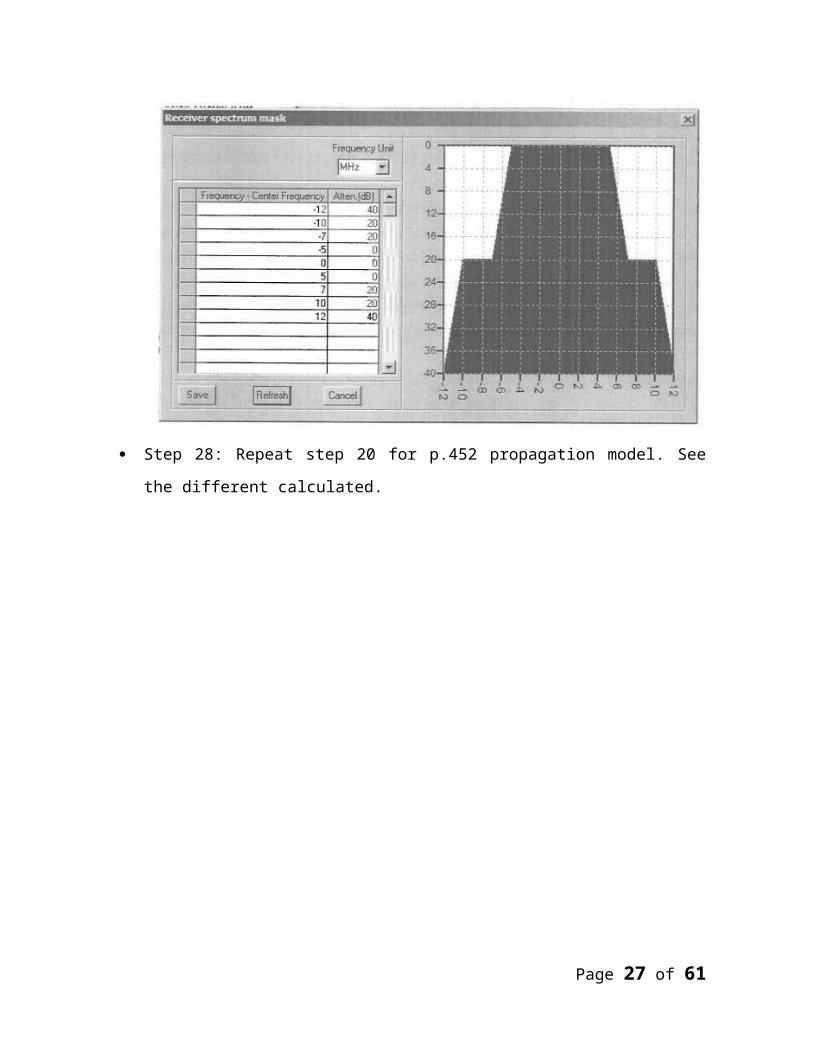
TX filter and shape it same as following figure.
Page 19 of 44
Step 27: For Stations A and B go to frequency level, and by using right click select RX
Filter and shape it same as following figure.
Step 28: Repeat step 20 for p.452 propagation model. See the different calculated.
Page 20 of 44

Exercise 16
GE84 Agreement
Step1: Establish BC station BCGE84 1 using ,set the frequency to 90 MHZ, power
1000w , and height of Antenna=100m
Step2: Open database menu and licensing, Anonymous stations and then find BCGE84
1 station and change its provision to GE84 Notice type to T01 . Step3: Open Coordination menu and the GE84 BC2BC(coord dis) select the country of
station and then BCGE84 1 push OK and see the results.
Step4: Open Coordination menu and the GE84 BC2FX select BCGE84 1 push OK and
see the results.
Step5: Open Coordination menu and the GE84 BC2LM select BCGE84 1 push OK
and see the results.
Step6: Open Coordination menu and the GE84 and then select(Interference from
country of station and then BCGE84 1 push OK and see the results.
Exercise 17
Page 21 of 44

Establishing Different digital plan entries based on GE06 Agreement
Single digital Broadcasting station (plan entry code=1)o Step 1: Create a BT station “ BTPEC1” with freq= 184.5 MHz , ANTHIGHT=
10, EIRP= 1000 W.
o Step 2: Open database menu and licensing and find “BTPEC1” Station and
change its provision to GENEVA 2006D and notice type to GT1, ADM REF
ID= BTPEC1, SITE ID= BTPEC1, Plan Entry code=1 , ASSIGNMENT
CODE= S then Push SAVE button.
o Step 3: Go to equipment level and set EQUIPMENT NAME = BTPEC1,
POWER TYPE= Mean power, Ref plan config= RPC1 the push SAVE button.
o Step 4: Go to frequency level and set type of spectrum mask = N then push
SAVE button.
o Step 5: Come back to main desktop and select “ Display GE06 plan Entry”
under DATABASE menu and then select BTPEC1 as wanted station to check
PEC.
Page 22 of 44

Exercise 18
Single- Frequency Network (PEC=2 i.e Stations linked with SFN with same SFN ID)
o Step 1: Create a BC station “ BCPEC21” with freq= 183.648 MHz ,
ANTHIGHT= 10, EIRP= 1000 W.
o Step 2: Create another BC station “ BCPEC22” with freq= 183.648 MHz ,
ANTHIGHT= 10, EIRP= 1000 W.
o Step 3: Open database menu and licensing and find “BCPEC21” Station and
change its provision to GENEVA 2006D and notice type to GS1, ADM REF
ID= BCPEC21, SITE ID= BCPEC21, Plan Entry code=2 , ASSIGNMENT
CODE= L then Push SAVE button.
o Step 4: Open database menu and licensing and find “BCPEC22” Station and
change its provision to GENEVA 2006D and notice type to GS1, ADM REF
ID= BCPEC22, SITE ID= BCPEC22, Plan Entry code=2 , ASSIGNMENT
CODE= L, SFN ID = BCPEC22 then Push SAVE button.
o Step 5: Go to equipment level of BCPEC21 and set EQUIPMENT NAME=
BCPEC21, Power TYPE =Mean Power, Ref plan Config= RPC4 the push
SAVE button.
o Step 6: Go to frequency level of BCPEC21 and set type of spectrum mask =1
then push SAVE button.
o Step 7: Go to equipment level of BCPEC22 and set EQUIPMENT NAME=
BCPEC22, Power TYPE =Mean Power, Ref plan Config= RPC4 the push
SAVE button.
o Step 8: Go to frequency level of BCPEC22 and set type of spectrum mask =1
then push SAVE button.
o Step 9: Select “Display GE06 plan Entry” under DATABASE menu and then
select BCPEC21 as Wanted station to check PEC.
Page 23 of 44

Exercise 19
Broadcasting allotment (PEC=3)
o Step 1: Open database menu and licensing and select New Allotment under
SMS4DC menu.
o Step 2 : Set allotment Name= BTPEC3 , Notice type to GT2, plan entry code=3
ADM REF ID = BTPEC3, SFN ID= BTPEC3 Freq= 191.5 MHz Country=
Your country , PPLARIZATION= V , Ref Net = RN1, Spectrum Mask= N,
RPC= RPC1 then push SAVE button.
o Step 3: Go to DEM map view and draw a poly line as desired allotment area.
o Step 4: Select “Define New allotment” under DATABASE. Menu and select
BTPEC3 as wanted allotment and Push OK.
o Step 5: Open database menu and licensing and select “BTPEC3” allotment and
find attached contour . with right click on It and selection of contour points see
test points of attached allotment area.
o Step 6: select “ Display GE06 plan entry” under DATABASE menu and then
select BTPEC3 as wanted allotment to check PEC.
Page 24 of 44

Exercise 20
An allotment with linked assignments and SFN identifier (PEC=4 i.e All linked assignments have Same SFN ID with allotment and in their Field of associated_adm_allot-id the Adm_ref_id of allotment is addressed).
o Step 1: Open database menu and licensing and select New Allotment under
SMS4DC menu.
o Step 2 : Set allotment Name= BTPEC4 , Notice type to GT2, plan entry code=4
ADM REF ID = BTPEC3, SFN ID= BTPEC4 Freq= 474 MHz Country= Your
country , PPLARIZATION= V , Ref Net = RN1, Spectrum Mask= N, RPC=
RPC1 then push SAVE button.
o Step 3: Go to DEM map view and draw a poly line as desired allotment area.
o Step 4: Select “Define New allotment” under DATABASE. Menu and select
BTPEC4 as wanted allotment and Push OK.
o Step 5: Open database menu and licensing and select “BTPEC4” allotment and
find attached contour . with right click on It and selection of contour points see
test points of attached allotment area.
o Step 6: Create BT station “BTPEC41” with freq=474 MHz, ANTHIGHT=10,
EIRP=1000W.
o Step 7: Create another BT station “BTPEC42” with freq=474 MHz,
ANTHIGHT=10, EIRP=1000W.
o Step 8: Open database menu and licensing and select “BTPEC41”station and
change its provision to GENEVA 2006D and Notice type to GT1, Plan entry
code=4, ADM REF ID= BTPEC41, SITE ID = BTPEC41, ASSIGNMENT
CODE=L , ASSOC ALLOT ID = BTPC4 , ASSOC ALLOT SFN ID=
BTPEC4, SFN ID= BTPEC4 then push SAVE button.
o Step 9: Open database menu and licensing and select “BTPEC42”station and
change its provision to GENEVA 2006D and Notice type to GT1, Plan entry
code=4, ADM REF ID= BTPEC42, SITE ID = BTPEC42, ASSIGNMENT
Page 25 of 44

CODE=L , ASSOC ALLOT ID = BTPC4 , ASSOC ALLOT SFN ID=
BTPEC4, SFN ID= BTPEC4 then push SAVE button.
o Step 10 : Go to equipment level of BTPEC 41 and set EQUIPMEN
NAME=BTPEC41 , POWER TYPE = Mean power, Ref plan Config = RPC1
then push SAVE Button.
o Step 11 Go to Frequency level of BTPEC41 and set type of spectrum Mask = N
then push SAVE button.
o Step 12 : Go to equipment level of BTPEC 42 and set EQUIPMEN
NAME=BTPEC42 , POWER TYPE = Mean power, Ref plan Config = RPC1
then push SAVE Button.
o Step 13 Go to Frequency level of BTPEC42 and set type of spectrum Mask = N
then push SAVE button.
o Step 14: select “ Display GE06 plan entry” under DATABASE menu and then
select BTPEC42 as wanted allotment to check PEC.
Page 26 of 44
Exercise 21
An allotment with linked assignments and SFN identifier (PEC=5 i.e All linked assignments have Same SFN ID with allotment and in their Field of associated_adm_allot-id the
Adm_ref_id of allotment is addressed).
o Step 1: Open database menu and licensing and select New Allotment under
SMS4DC menu.
o Step 2 : Set allotment Name= BTPEC4 , Notice type to GT2, plan entry code=5
ADM REF ID = BTPEC5, SFN ID= BTPEC4 Freq= 474 MHz Country= Your
country , PPLARIZATION= V , Ref Net = RN1, Spectrum Mask= N, RPC=
RPC1 then push SAVE button.
o Step 3: Go to DEM map view and draw a poly line as desired allotment area.
o Step 4: Select “Define New allotment” under DATABASE. Menu and select
BTPEC5 as wanted allotment and Push OK.
o Step 5: Open database menu and licensing and select “BTPEC5” allotment and
find attached contour . with right click on It and selection of contour points see
test points of attached allotment area.
o Step 6: Create BT station “BTPEC51” with freq=474 MHz, ANTHIGHT=10,
EIRP=1000W.
o Step 7: Open database menu and licensing and select “BTPEC51”station and
change its provision to GENEVA 2006D and Notice type to GT1, Plan entry
code=5, ADM REF ID= BTPEC51, SITE ID = BTPEC51, ASSIGNMENT
CODE=L , ASSOC ALLOT ID = BTPC5 , then push SAVE button.
o Step 8 : Go to equipment level of BTPEC 51 and set EQUIPMEN
NAME=BTPEC51 , POWER TYPE = Mean power, SYS VAR.= A1, RX
MODE = FX then push SAVE Button.
o Step 9: Go to Frequency level of BTPEC51 and set type of spectrum Mask = N
then push SAVE button.
Page 27 of 44

o Step 10: select “ Display GE06 plan entry” under DATABASE menu and then
select BTPEC51 as wanted allotment to check PEC.
Page 28 of 44
Exercise 22
Analogue Broadcasting station
o Step 1: Create BT Station” BTPEC00” with Freq= 482 MHz, ANTHIGHT= 10
EIRP=1000w.
o Step 2: Open database menu and licensing and select “BTPEC00”station and
change its provision to GENEVA 2006A and Notice type to G02, ADM REF
ID= BTPEC00, SITE ID = BTPEC00, then push SAVE.
o Step 3: Go to equipment level of BTPEC00 and set EQUIPMENT
NAME=BTPEC00 , POWER TYPE = Mean power, TV SYS.= G, TV color=
PAL, Power radio=10, Frequency Stability= Normal then push SAVE button.
o Step 4: Go to Frequency level and set Vision Carrier frequency =479.25 MHz,
Sound carrier Frequency =484.75 and then push SAVE button.
o
Page 29 of 44

Exercise 23
GE06 BCNT2BCBT AFFECTED ADMINISTRATIONS
Step I: Open "Coordination" menu and GE06 and BCBT2BCBT (affected ADM) select
BTPEC1 station and push OK
Step 2: Set Azimuth step=l, Search radius=1000 km and push OK and analyze the
results
Step 3: Open "Coordination" menu and GE06 and BCBT2BCBT (affected ADM) select
BTPEC 4 station and push ok
Step 4: Set Azimuth step=l, Search radius=1000 km and push OK and analyze the
results.
Page 30 of 44

Exercise 24
GE06 BCNT2FXM AFFECTED ADMINISTRATIONS
Step I: Create BT station “ BTFXM1” with freq = 818 MHz , ANTHIGHT = 10, EIRP
= 1000 W.
Step 2: Open database menu and licensing and find “ BTFXM1” station and change its
provision to GENEVA 2006D and Notice type to GT1, ADM REF ID = BTFXM1,
SITE ID= BTFXM1, plan entry code=1 ASSIGNMENT CODE= S then push SAVE
button.
Step 3: Go to frequency level and set EQUIPMENT NAME= BTFXM1, POWER
TYPE= Mean power , REF plan config = RPC1 then push SAVE button.
Step 4: go to frequency level and set type of spectrum mask = N then push SAVE
button.
Step 5: Come back to main desktop and select “Display GE06 plan entry” Under
database menu and then select BTFXM1 as wanted station to check PEC.
Step 6: Create a fixed station in your neighboring country in fixed service (FX GE06-1)
with service = Fixed and class of station = FX and freq=818 MHz and Antenna Height
=10m , Power = 10 W.
Step 7: Open database menu and licensing and find “ FX GE06-1” station and change
its provision to GENEVA 2006L and Notice type to G11 Site ID= FX GE06-1 and then
push SAVE Button.
Step 8: Go to equipment level and set EQUIPMENT NAME = FX GE06-1, POWER
TYPE= Mean Power , System type1= FF then Push SAVE Button.
Step 9: Go to frequency level and set response frequency =818 MHz then push SAVE
Button.
Step 10: Open “ Coordination “ Menu and GE06 and BCBT2FXM (affected ADM)
select BTFXM1 Assignment and push OK.
Step 11: Set Azimuth Step=1, Search radius = 1000 Km and push OK.
Step 12: Select the found trigger FS then push OK to see the results.
Page 31 of 44
Exercise 25
GE06 FXM2 BCBT AFFECTED ADMINISTRATIONS
Step 1: Open “coordination” Menu and GE06 and FXM2BCBT (affected ADM) and
TX station and then select FXGE06-1 station and push OK.
Step 2: Set Azimuth step=1, Search radius = 1000 km and push OK and analyze the
results.
Step 3: Open “ Coordination” Menu and GE06 and FXM2BCBT (affected ADM) and
RX station and then select FXGE06-1 station and push OK.
Step 4: Set azimuth step=1 , Search radius =1000 km, DVB 8 MHz and push OK and
analyze the results.
Page 32 of 44

Exercise 26
GE06 Coverage Area and service Area
Step 1: Open “Coordination” menu an GE06 and coverage Area then select BTPEC1
assignment and push OK
Step 2: Set parameters and push OK
Step 3: Select line width and color of noise - limited coverage area contour and push
OK to continue.
Step 4: Select all found interferer assignments/allotment and push OK
Step 5: Select line width and color of interference - limited coverage area contour and
push OK
Step 6: Compare noise -limited and interference coverage area
Step 7: Open “Coordination” menu and GE06 and service Area then select New
Assignments, Number of test points =12 and push OK
Step 8: Select BTPEC1 assignment and push OK
Step 9: Set parameters and push OK
Step 10: Select line width and color of service area contour push OK
To continue after calculation save results.
Step 11 : Repeat steps 7 to 10 for other assignments which have been created in
previous exercises.
Page 33 of 44

Exercise 27
GE06 Interference To and Interference From
Step 1: Open “Coordination” menu an GE06 and coverage Area and interference to and
BCBT2DBCBT then select BTPEC1 assignment (as Interferer) and push OK.
Step 2: Set parameters and Push OK
Step 3: Select all found victim assignment/allotments and push OK to see the results.
Step 4: Open “coordination” menu and GE06 and Interference From and
BCBT2DBVBT then select BTPEC1 assignment (as victim) and push OK.
Step 5: Set parameters and push OK.
Step 6: Select all found interferer assignments/allotments and push OK to see results.
Page 34 of 44

Exercise 28
AGREEMENTS
Model 1 TYPE A
Step 1: Launch the SMS4DC software
Step 2: Launch the DEM view using toolbar push button.
Step 3: Open the menu “COORDINATION” and select AGREEMENTS item
Step 4: By choosing icon create a new agreement YEMOM
Step 5: Choose Fixed and land Mobile as services by pushing icon
Step 6: Set Model to 1 and type to 1
Step 7: Open list of countries and select YEM and OM then push OK
Step 8: Open list of propagation Models and select FREE SPACE
Step 9: Insert LoFreq=100,HiFreq= 170,PIFS=12,CBR=80,ERP=12,Emergency=0
Step 10: Push the “save” button,
Step 11: Establish a FB station (with the name YEM FBAGR1) in YEM with the
Freq=160 MHZ
Step 12: OPEN the menu “COORDINATION” and select ‘Border’ item
Step 13: Select the station YEMFBAGR1
Step 14: Select the existing agreement that was found by software
Step 15: Set search radius and push OK
Step 16: After calculation compare Max Eb ,Max Ec and PIFS
Step 17: Move YEMFBAGR1 station by using of icon and repeat Item 13-16
Page 35 of 44

Exercise 29
AGREEMENTS
Model 1 TYPE B
Step 1: Launch the SMS4DC software
Step 2: Launch the DEM view using toolbar push button.
Step 3: Open the menu “COORDINATION” and select AGREEMENTS item
Step 4: By choosing icon create a new agreement YEMOM1
Step 5: Choose Fixed and land Mobile as services by pushing icon
Step 6: Set Model to 1 and type to 1
Step 7: Open list of countries and select YEM and OM then push OK
Step 8: Insert Lo Freq=3000,HiFreq= 6000,Coord dist1=100Km,Coord
dist2=100Km ,Emergency=0.
Step 9: Push the “save” button,
Step 10: Establish a Fx station (with the name YEM FxAGR1) in JOR with the
Freq=4000 MHZ
Step 11: OPEN the menu “COORDINATION” and select ‘Border’ item
Step 12: Select the station YEMFBAGR1.
Step 13: Select the existing agreement that was found by software
Step 14: After calculation compare MIN Distance and COORD DIST
Step 15: Move YEMFXAGR1 station by using of icon and repeat Item 11-14
Page 36 of 44

Exercise 30
AGREEMENTS
Model 2
Step 1: Launch the SMS4DC software.
Step 2: Launch the DEM view using toolbar push button.
Step 3: Open the menu “COORDINATION” and select AGREEMENTS item
Step 4: By choosing icon create a new agreement YEMOM3
Step 5: Choose Fixed and LM as services by pushing icon
Step 6: Set Model to 2 and propagation model to “FREE SPACE” type to 1
Step 7: Open list of countries and select SOM and DJ then push OK
Step 8: Insert Lo Freq=200,HiFreq= 300,Pref country=SYR ,
PIFS=12,XKM=80,ERP=12 Emergency=0
Step 9: Insert Lo Freq=300,HiFreq= 300,Pref country=SYR ,
PIFS=12,XKM=80,ERP=12 Emergency=0
Step 10: Push the “save” button.
Step 11: Establish a FX station (with the name YEM FxAGR1) in YEM with the
Freq=250 MHz
Step 12: OPEN the menu “COORDINATION” and select ‘Border’ item.
Step 13: Select the station YEMFBAGR3.
Step 14: Select the YEMOM agreement that was found by software
Step 15: Establish another FX station with the name YEM FxAGR4) in YEM with the
Freq=350 MHz.
Step 16: repeat Item 12-16.
Step 15: Move YEMFXAGR1 station by using of icon and repeat Item 11-14
Page 37 of 44

Exercise 31
BC to BC Interference
Step 1: create YEMBC1 station with freq=107MHZ,power=10W,and antenna
height=10m.
Step 2: create YEMBC2 station near to YEMBC1 station with freq=107MHZ,
power=10W,and antenna height=10m.
Step 3: open (database) menu and select licensing.
Step 4 :set provision of YEMBC1and YEMBC2 station to article 11 and notice type to
T01.
Step 5: open the menu (interference) and select(BC 2 BC)item.
Step 6: select YEMBC1 station and push OK.
Step 7: set search radius ,and Min. FS and push OK.
Step 8: select YEMBC2 station as interferer station and state calculation .
Step 9: compare coverage area with and without interference .
Step 10: change to main window and from propagation model select overlay item and
choose the interference BC 2 BC results.
Page 38 of 44

Exercise 32
BT to BT Interference
Step 1: create YEMBT1 station with :
o assign freq=714MHz.
o power=1000W
o antenna height=10m
o provision=article 11
o notice type=T02
o vision freq=711.25MHz
o sound freq=716.75.
o color=pal.
o power ratio=10
o TVsys =G
o class of EMISSION=C3E
o bandwidth=8000KHz.
Step 2: create YEMBT2station with:
o assign freq=714MHz
o power=1000w
o antenna height=10m
o provision=article 11
o notice type=T02
o vision freq=711.25MHz
o sound freq=716.75
o color=pal
o power ratio=10
o TV sys =G
o class of EMISSION=C3E
Page 39 of 44

o bandwidth=8000KHz.
Step 3: open the menu (interference)and select(BT 2 BT)item.
Step 4 : select YEMBT1 station and push OK.
Step 5: set search radius, and Min. FS and push OK.
Step 6: select YEMBT2 station as interferer station and state calculation .
Step 7: compare coverage area with and without interference.
Step 8: change to main window and from propagation model select overlay item and
choose the interference BT 2 BT results.
Page 40 of 44

Exercise 33
Interference FX
Step 1: Launch the SMS4DC software
Step 2: Launch the DEM view using toolbar push button.
Step 3: Establish Fixed station UAEFX11 using , set the frequency to 6000MHZ ,
power=50W and height of antenna=10m
Step 4: Establish Fixed station UAEFX22 using ,set the frequency to
hig6000MHZ,power=50W,and height of antenna=10m
Step 5: open the administrative part from “data base->Licensing”
Step 6: Find the station UAEFX11 and go to the level of “Frequency”
Step 7: push the “Add Receiver “button top of the “Frequency Information “table of
station UAEFX11.The “Add Receiver” dialog box will appear.
Step 8: Select the “Point” Radio button .All the selectable receivers will be displayed in
relevant spreadsheet
Step 9: Choose the station UAEFX22 from table under POINT section and push ok
Step 10: Close Administrative dialog box
Step 11: Establish Fixed station UAEFX33 using ,set the frequency to
hig6000MHZ, power=50W,and height of antenna=10m
Step 12: Establish Fixed station UAEFX44 using ,set the frequency to hig
6000MHZ,power=50W,and height of antenna=10m
Step 13: open the administrative part from “data base->Licensing”
Step 14: Find the station UAEFX33 and go to the level of “Frequency”
Step 15: push the “Add Receiver “button top of the “Frequency Information “table of
station UAEFX33.The “Add Receiver” dialog box will appear.
Step 16: Select the “Point” Radio button .All the selectable receivers will be displayed
in relevant spreadsheet
Step 17: Choose the station UAEFX44 from table under POINT section and push ok
Step 18: Close Administrative dialog box
Page 41 of 44

Step 19: open the “Database “menu and select “Display Link “
Step 20: Select the record of new established hops
Step 21: Push ok button to display station of selected hops on map
Step 22: Open the menu “Interference” and select FX2FX(LINK) and “Interference to”
Step 23: select one of the hops was created by previous steps
Step 24: Set parameters and push OK then select all found hops and push OK
Step 25: open the menu “Interference” and select FX2FX (station) and “Interference to”
Step 26: select one of the stations was created by previous steps
Step 27: Set parameters and push OK then select all found hops and push
Step 28: Compare the result with the result of step 24
Page 42 of 44

Exercise 34
Interference FXM
Step1: Launch the SMS4DC software
Step 2: Launch the DEM view using toolbar push button.
Step3: Establish LM station UAEB1 using ,set the frequency to 150MHZ,and
height of Antenna=10m
Step4: Establish LM station UAEB2 using ,set the frequency to 150MHZ,and
height of Antenna=10
Step5: Open the menu “Interference” and select” FXM” and Interference to (FREE
SPACE)
Step6: select station UAEFB1 and push OK
Step7: set parameters and push OK then select UAEFB2 station and push OK
Step8: Open the menu “Interference” and select” FXM” and Interference to (P.1546)
Step9: select station UAEFB1 and push OK
Step10: set parameters and push OK then select UAEFB2 station and push OK
Step11: compare the results with the result of step7
Page 43 of 44

Exercise 35
Interference: ES to/from FX
Step 1: Launch the SMS4DC software
Step 2: Launch the DEM view using toolbar push button.
Step 3: Open the menu “DATABASE” and select “Earth Stations in Desktop” item.
Step 4: Sort stations by NIG as Country.
Step 5: Select earth station in NIG and push OK.
Step 6: Find your Earth station on map.
Step 7: Create FX station with name NIGFXES1 near to EARTH station with Tx
Freq=400MHz and power =50 w and height of Antenna=10m.
Step 8: Open the menu “DATABASE” and select “LICESING” and find FX and go to
frequency level and change the response frequency to 6000MHZ.
Step 9: Open the menu “DATABASE” and select “LICESING” and find ES and fill
nominal longitude of space station .
Step 10: open the menu “Interference” and select “ES2FX”.
Step 11: Choose NIG.
Step 12: Choose station YEMTEST and push OK.
Step 13: Set parameters and push OK
Step 14: Open the menu “Interference” and select “FX2ES”.
Step 15: Repeat step 11 to 13.
Page 44 of 44