viesmann vitoplex 200 - parat.no · rated heating output kw 90 120 150 200 270 350 440 560 standby...
TRANSCRIPT

VIESMANN VITOPLEX 200Low temperature oil/gas boiler
90 to 560 kW
VITOPLEX 200 Type SX2A
Low temperature oil/gas boilerThree-pass boilerFor operation with modulating boiler water temperature.With the Vitotrans 300 as a condensing unit.
5728 770 GB 5/2011
DatasheetPart no. and prices: see pricelist

■ Economical and environmentally responsible through modulatingboiler water temperature.
■ Standard seasonal efficiency [to DIN] for operation with fuel oil: 89% (Hs[gross cv])/95 % (Hi[net cv]).
■ Optional stainless steel flue gas/water heat exchanger for higherstandard seasonal efficiency through the utilisation of condensingtechnology.
■ Three-pass boiler with low combustion chamber loading, resulting inclean combustion with low emissions.
■ Wide water galleries and large water content provide excellent nat-ural circulation and safe heat transfer.
■ Integral Therm-Control start-up system for easy hydraulic connec-tions – no shunt pump or return temperature raising facility required.
■ No low water indicators required up to 300 kW.■ Compact design for easy handling and economical use of space –
important for modernisation projects.■ Vitoflame 100 to 270 kW Unit pressure-jet oil/gas burners are avail-
able.■ Fastfix assembly system for control unit and thermal insulation.
A Wide water galleries and large water content ensure excellentnatural circulation and easy hydraulic connection
B Third hot gas flueC Highly effective thermal insulationD Vitotronic – the new generation of controllers: Intelligent and easy
to install, operate and serviceE Viessmann Vitoflame 100 Unit burnerF Thermal insulation of boiler doorG Second hot gas flueH Combustion chamber
Benefits at a glance
2 VIESMANN VITOPLEX 200
5728
770
GB

Specification
Rated heating output kW 90 120 150 200 270 350 440 560Rated heat input kW 98 130 163 217 293 380 478 609CE designation – according to the Efficiency Direc-tive
CE-0085BQ0020 — —
– according to the Gas AppliancesDirective
CE-0085BQ0020
Permiss. flow temperature(= safety temperature)
°C 110 (to 120 °C on request)
Permiss. operating temperature °C 95Permiss. operating pressure bar 4Pressure drop on the hot gas side Pa 60 80 100 200 180 310 280 400
mbar 0.6 0.8 1.0 2.0 1.8 3.1 2.8 4.0Boiler body dimensions Length (dim. q)*1 mm 1195 1400 1385 1580 1600 1800 1825 1970Width (dim. d) mm 575 575 650 650 730 730 865 865Height (incl. connectors) (dim. t) mm 1145 1145 1180 1180 1285 1285 1455 1455Overall dimensions Total length (dim. r) mm 1260 1460 1445 1640 1660 1860 1885 2030Total length with burner and hood(dim. s)
mm 1660 1860 1865 2060 2085 – – –
Total width (dimension e) mm 755 755 825 825 905 905 1040 1040Total height (dim. b) mm 1315 1315 1350 1350 1460 1460 1625 1625Maintenance height (control unit)(dim. a)
mm 1485 1485 1520 1520 1630 1630 1795 1795
Height – adjustable anti-vibration feet mm 28 28 28 28 28 28 28 28– anti-vibration boiler supports (loa-ded)
mm – – – – – 37 37 37
Foundations Length mm 1000 1200 1200 1400 1400 1650 1650 1800Width mm 760 760 830 830 900 900 1040 1040Combustion chamber diameter mm 380 380 400 400 480 480 570 570Combustion chamber length mm 800 1000 1000 1200 1200 1400 1400 1550Weight boiler body kg 300 345 405 455 630 700 925 1025Total weight kg 345 390 455 505 680 760 990 1095Boiler with thermal insulation andboiler control unit
Total weight kg 375 420 485 535 710 – – –Boiler with thermal insulation, burnerand boiler control unit
Content boiler water litres 180 210 255 300 400 445 600 635Boiler connections Boiler flow and return PN 6 DN 65 65 65 65 65 80 100 100Safety connection(safety valve)
R 1¼ 1¼ 1¼ 1¼ 1¼ 1¼ 1½ 1½
Drain R 1¼Flue gas parameters*2 Temperature (at boiler water temper-ature 60 °C)
– at rated heating output °C 180– at partial load °C 125Temperature (at boiler water temper-ature 80 °C)
°C 195
Flue gas mass flow rate – for natural gas kg/h 1.5225 x combustion output in kW– for fuel oil EL kg/h 1.5 x combustion output in kWRequired draught Pa/mbar 0Flue outlet Ø mm 180 180 200 200 200 200 250 250Standard seasonal efficiency [toDIN](for operation with fuel oil)at heating system temp. 75/60 °C
% 89 (Hs[gross cv])/95 (Hi[net cv])
*1 Boiler door removed.*2 Values for calculating the size of the flue system to EN 13384 relative to 13.2 % CO2 for fuel oil EL and 10 % CO2 for natural gas.
Flue gas temperatures as actual gross values at 20 °C combustion air temperature.The details for partial load refer to 60 % of the rated heating output. Calculate the flue gas mass flow rate accordingly if the partial load differsfrom that stated (subject to operating mode).
Boiler specification
VITOPLEX 200 VIESMANN 3
5728
770
GB

Rated heating output kW 90 120 150 200 270 350 440 560Standby loss qB,70 % 0.40 0.35 0.30 0.30 0.25 0.25 0.22 0.20Matching Vitotrans 300 – operation with gas Part no. Z000 701 Z000 702 Z002 118 Z000 704– operation with fuel oil Part no. Z000 705 Z000 706 Z002 120 Z000 708Rated heating output Boiler with Vitotrans 300
– operation with gas kW 98.7 131.4 164.3 219.0 295.6 383.3 478.7 608.9– operation with fuel oil kW 95.8 127.8 159.8 213.0 287.5 372.7 466.4 593.5CE designation CE-0085BS0287Vitotrans 300 in conjunction with aboiler as a condensing unit
Pressure drop on the hot gas sideBoiler with Vitotrans 300
Pa 125 145 185 285 280 410 385 505mbar 1.25 1.45 1.85 2.85 2.80 4.10 3.85 5.05
Total lengthBoiler with Vitotrans 300without burner
mm 1990 2290 2570 2950
Dimensions
a
ed
cb
E
RAGA
t
n
KR
k
m
s
f
KTÜ
SCH
q
r
TSA
MA
KV
SA KTS
hg
l
o 87p
90 to 270 kW
AGA Flue outletE DrainKR Boiler returnKTS Boiler water temperature sensorKTÜ Boiler doorKV Boiler flow
MA Female connection for pressure gauge (R ½)R Cleaning apertureSA Safety connection (safety valve)SCH Inspection portTSA Female connection for Therm-Control temperature sensor
(R ½)
Boiler specification (cont.)
4 VIESMANN VITOPLEX 200
5728
770
GB

KTS
n
KR
h
m
q
r
a
ed
cb
E
RAGA
t
TSA DB KV
SA RG
l
g
KTÜ
fk
o 87p
SCH
350 to 560 kW
AGA Flue outletDB Female connection for maximum pressure limiter (R ½)E DrainKR Boiler returnKTS Boiler water temperature sensorKTÜ Boiler doorKV Boiler flow
R Cleaning apertureRG Female connection for additional control equipment (R ½)SA Safety connection (safety valve)SCH Inspection portTSA Female connection for Therm-Control temperature sensor
(R ½)
DimensionsRated heating output kW 90 120 150 200 270 350 440 560a mm 1485 1485 1520 1520 1630 1630 1795 1795b mm 1315 1315 1350 1350 1460 1460 1625 1625c mm 1085 1085 1115 1115 1225 1225 1395 1395d mm 575 575 650 650 730 730 865 865e mm 755 755 825 825 905 905 1040 1040f mm 440 440 440 440 420 420 470 470g mm 622 825 811 1009 979 1179 1146 1292h mm 307 395 324 423 409 609 710 783k mm 203 203 203 203 203 203 224 224l mm 165 165 151 151 153 153 166 166m mm 860 860 885 885 960 960 1110 1110n mm 200 200 190 190 135 135 135 135o mm 110 110 110 110 130 130 130 130p (length of base rails) mm 882 1085 1071 1268 1269 1469 1471 1617q (transport dimension) mm 1195 1400 1385 1580 1600 1800 1825 1970r mm 1260 1460 1445 1640 1660 1860 1885 2030s mm 1670 1875 1880 2075 2095 – – –t mm 1145 1145 1180 1180 1285 1285 1455 1455
The boiler door can be removed if access to the boiler room is restricted.
Dim. f: Observe the installed height of the burner.Dim. q: Boiler door removed.
Boiler specification (cont.)
VITOPLEX 200 VIESMANN 5
5728
770
GB

Siting
Minimum clearances
200 (100)
500 (50)400 a
b
500 (50)
(300)
A BoilerB BurnerC Adjustable anti-vibration feet (90 to 560 kW) or anti-vibration
boiler supports (350 to 560 kW)
To enable convenient installation and maintenance, observe the sta-ted clearance dimensions; maintain the minimum clearances wherespace is tight (dimensions in brackets). In the delivered condition, theboiler door opens to the left. You can reposition the hinge bolts so thatthe door can open to the right.
Rated heating output kW 90 120 150 200 270 350 440 560a mm 1100 1400 1600
Dim. a: Maintain this space in front of the boiler to enable the with-drawal of the turbulators or for cleaning the hot gas flues.
Dim. b: Observe the installed length of the burner.
Installation conditions■ Avoid air contamination by halogenated hydrocarbons
(e.g. as contained in sprays, paints, solvents and cleaning agents)■ Avoid very dusty conditions■ Avoid high levels of humidity■ Prevent frost and ensure good ventilation
Otherwise, the system may suffer faults and damage.In rooms where air contamination through halogenated hydrocar-bons may occur, install the boiler only if adequate measures can betaken to provide a supply of uncontaminated combustion air.
Burner installationBoiler up to 120 kW:The burner fixing hole circle, burner fixing holes and blast tube aper-ture meet the requirements of EN 226.Boiler from 150 kW:The burner fixing hole circle, burner fixing holes and blast tube aper-ture comply with the following table.The burner may be fitted directly to the hinged boiler door. Fit theburner plate included in the standard delivery if the burner dimensionsdeviate from those stated in the following table.Burner plates may be factory-fitted on request (chargeable option). Forthis, please state the burner make and type when ordering. The blasttube must protrude through the thermal insulation on the boiler door.
45°
cb
a
110
de
Rated heating output kW 90 120 150 200 270 350 440 560a Ø mm 135 135 240 240 240 240 290 290b Ø mm 170 170 270 270 270 270 330 330c number/thread 4/M 8 4/M 8 4/M 10 4/M 10 4/M 10 4/M 10 4/M 12 4/M 12
Boiler specification (cont.)
6 VIESMANN VITOPLEX 200
5728
770
GB

Rated heating output kW 90 120 150 200 270 350 440 560d mm 440 440 440 440 420 420 470 470e mm 650 650 650 650 670 670 780 780
Pressure drop on the heating water side
0.1Diff
eren
tial p
ress
ure
in m
bar
1 10010
1
10
100
1000
Flow rate in m³/h
A Rated heating output of 90 to 270 kWB Rated heating output 350 kWC Rated heating output 440 and 560 kW
The Vitoplex 200 is only suitable for fully pumped hot water heatingsystems.
Boiler specification (cont.)
VITOPLEX 200 VIESMANN 7
5728
770
GB

Specification
Vitotrans 300 – Gas operation Part no. Z000 701 Z000 702 Z002 118 Z000 704– Oil operation Part no. Z000 705 Z000 706 Z002 120 Z000 708Rated boiler output kW 90-125 140-200 230-350 380-560Rated output range of the Vitotrans300 for
– Gas operation from kW 8.7 12.7 21.8 33.3 to kW 11.9 19.0 33.3 48.9– Oil operation from kW 5.8 8.8 14.9 22.9 to kW 8.1 13.0 22.7 33.5Permiss. operating pressure bar 4 6Permissible flow temperature(= safety temperature)
°C 110
Hot gas pressure drop Pa 65 85 100 105 mbar 0.65 0.85 1.00 1.05Flue gas temperature – Gas operation °C 65– Oil operation °C 70Flue gas mass flow rate from kg/h 136 213 383 546 to kg/h 213 341 596 954Overall dimensions Total length (dimension h), incl. mat-ing flanges
mm 666 777 856 967
Total width (dimension b) mm 714 760 837 928Total height (dimension c) mm 1037 1152 1167 1350Transport dimensions Length excl. mating flanges mm 648 760 837 928Width (dimension a) mm 618 636 706 839Height (dimension d) mm 1081 1098 1172 1296Heat exchanger weight kg 94 119 144 234Total weight kg 125 150 188 284Heat exchanger with thermal insulation Capacity Heating water litres 70 97 134 181Flue gas m3 0.055 0.096 0.133 0.223Connections Heating water flow and return DN 40 50 50 65Condensate drain R ½Flue gas connection – to the boiler NW 180 200 200 250– to the flue system NW 150 200 200 250
Rated output range of the Vitotrans 300 and flue gas temperatureOutput of the Vitotrans 300 for flue gas cooling during gas operationof 200/65 °C, during oil operation of 200/70 °C and a heating watertemperature rise in the Vitotrans 300 of 40 °C to 42.5 °C.For conversion to other temperatures, see chapter "Output data".
Hot gas pressure dropHot gas pressure drop at rated output. The burner must be able toovercome the hot gas pressure drop of the boiler, that of theVitotrans 300 and that of the flue. Viessmann Vitoflame 100 burnersare unsuitable for use with the Vitotrans 300.
Approved qualityCE designation according to current EC Directives at a permis-sible flow temperature (safety temperature) of up to 110 °C toEN 12828.
Vitotrans 300 specification
8 VIESMANN VITOPLEX 200
5728
770
GB
Dimensions
18-4
0
R
c
h
b
a
d
e
fE
KOA
g
R
HV
HR
AGA
i
k l
m
A
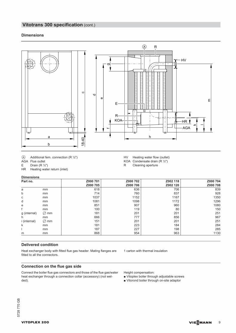
A Additional fem. connection (R ½")AGA Flue outletE Drain (R ½")HR Heating water return (inlet)
HV Heating water flow (outlet)KOA Condensate drain (R ½")R Cleaning aperture
DimensionsPart no. Z000 701 Z000 702 Z002 118 Z000 704 Z000 705 Z000 706 Z002 120 Z000 708a mm 618 636 706 839b mm 714 760 837 928c mm 1037 1152 1167 1350d mm 1081 1098 1172 1296e mm 851 907 960 1080f mm 100 119 80 150g (internal) 7 mm 181 201 201 251h mm 666 777 856 967i (internal) 7 mm 151 201 201 251k mm 181 223 184 284l mm 187 227 198 285m mm 868 954 963 1130
Delivered conditionHeat exchanger body with fitted flue gas header. Mating flanges arefitted to all the connectors.
1 carton with thermal insulation
Connection on the flue gas sideConnect the boiler flue gas connectors and those of the flue gas/waterheat exchanger through a connection collar (accessory) (not wel-ded).
Height compensation:■ Vitoplex boiler through adjustable screws■ Vitorond boiler through on-site adaptor
Vitotrans 300 specification (cont.)
VITOPLEX 200 VIESMANN 9
5728
770
GB

Pressure drop on the heating water side
Part no. Z000 701, Z000 702, Z000 704, Z000 705, Z000 706,Z000 708, Z002 118 and Z002 120
108654
3
2
1
1520
1 2 4 5 6 8 10Flow rate in m³/h
Pres
sure
dro
p in
mba
r
30
3 15 20
D
C
BA
Part no. CurveZ000 701 AZ000 705 Z000 702 BZ000 706 Z002 118 CZ002 120 Z000 704 DZ000 708
Output data
Vitotrans 300 for gas operation
70 65 60 55 50 45 40 35 30 25 20750.4
0.6
0.8
1
1.2
1.4
Con
vers
ion
fact
or
Heating water inlet temperature in °C
B
A
A Flue gas inlet temperature 200 °CB Flue gas inlet temperature 180 °C
Conversion of the output dataThe output data of the Vitotrans 300 flue gas/water heat exchangerrefers to a flue gas inlet temperature of 200 °C and a heating waterinlet temperature into the heat exchanger of 40 °C.
For different conditions the output can be calculated by multiplying thegiven rated output by the conversion factor established from the dia-gram.
Boiler delivered condition
Boiler body with fitted boiler door and cleaning cover.Mating flanges are fitted to all connectors.Adjustable feet are supplied in the combustion chamber.Cleaning equipment can be found on top of the boiler.
2 Cartons with thermal insulation1 Carton containing the boiler control unit and 1 bag with technical
documentation1 Therm-Control
Vitotrans 300 specification (cont.)
10 VIESMANN VITOPLEX 200
5728
770
GB

1 Product pack (boiler coding card and Vitoplex 200 technical doc-umentation)
1 Burner plate (from 150 kW)
■ Vitoplex 200, 90 to 270 kW:Vitoflame 100 pressure-jet oil or gas burner, subject to order.
■ Vitoplex 200, 350 to 560 kW:Suitable pressure-jet oil/gas burners are available from Weishauptor ELCO (see pricelist) and should be ordered separately. Deliverydirect from Weishaupt or ELCO.
Control unit versions
For single boiler systems:■ Vitotronic 100 (type GC1B)
Boiler control unit for constant boiler water temperature■ Vitotronic 200 (type GW1B)
Weather-compensated boiler control unit■ Vitotronic 300 (type GW2B)
Weather-compensated boiler and heating circuit control unit for upto 2 heating circuits with mixers
■ Vitotronic 200-H (type HK1B or HK3B)Weather-compensated heating circuit control unit for 1 or up to 3heating circuits with mixers
■ Vitocontrol control panel
For multi boiler systems (up to 4 boilers):■ Vitotronic 100 (type GC1B) and LON module with Vitotronic 300-
K (type MW1B)For weather-compensated cascade control of up to 4 boilers andcontrol of up to 2 heating circuits with mixers.(The first boiler is delivered with the standard control equipment forthe multi boiler system.)
■ Vitotronic 100 (type GC1B) and LON module for every additionalboiler in the multi boiler system
■ Vitotronic 200-H and LON module (type HK1B or HK3B) for 1 orup to 3 heating circuits with mixers
■ Vitocontrol control panel
Boiler accessories
See pricelist and "Boiler accessories" datasheet.
Operating conditions with Vitotronic boiler control units
For water quality requirements, see the technical guide to this boiler.
RequirementsOperation with burner load ≥ 60 % < 60 %1. Heating water flow rate None 2. Boiler return temperature (minimum
value)*3None*4
3. Lower boiler water temperature – Operation with fuel oil 50 °C – Operation with fuel oil 60 °C– Operation with gas 60 °C – Operation with gas 65 °C
4. Two-stage burner operation Stage 1: 60 % of rated heating output No minimum load required5. Modulating burner operation Between 60 and 100 % of rated heating output No minimum load required6. Reduced mode Single boiler systems and lead boiler of multi boiler systems
– operation with the lower boiler water temperature Lag boilers of multi boiler systems
– Can be shut down
7. Weekend setback As per reduced mode
Design information
Installation of a suitable burnerThe burner must be suitable for the relevant rated heating output andthe pressure drop on the hot gas side of the boiler (see burner manu-facturer's specification).The material of the burner head must be suitable for operating tem-peratures of at least 500 °C.
Pressure-jet oil burnerThe burner must be tested and designated to EN 267.
Pressure-jet gas burnerThe burner must be tested to EN 676 and CE-designated in accord-ance with Directive 2009/142/EC.
Burner adjustmentAdjust the oil or gas throughput of the burner to suit the rated boilerheating output.
*3 The technical guide (system examples) contains relevant examples for the installation of the Therm-Control start-up system.*4 No requirements; only in conjunction with Therm-Control.
Boiler delivered condition (cont.)
VITOPLEX 200 VIESMANN 11
5728
770
GB

Low water indicatorA low water indicator to EN 12828 is not required for Vitoplex 200 boil-ers up to 300 kW (except in attic heating centres), if the standard boilercontrol unit is fitted as per the installation instructions.
In the event of a water shortage due to a leak in the heating systemand simultaneous burner operation, the burner control unit will beautomatically shut down before the boiler and/or flue system reachunacceptably high temperatures.
Permissible flow temperatures
Hot water boilers for permissible flow temperatures (= safety temper-atures)
■ up to 110 °CCE designation:CE-0085 (90 to 350 kW) in accordance with the Efficiency DirectiveandCE-0085 in accordance with the Gas Appliances Directive
■ Above 110 °C (up to 120 °C) (with individual acceptance on request)CE designation:CE-0035 according to the Pressure Equipment DirectiveAdditional safety equipment is required for operation with a safetytemperature above 110 °C.– 90 and 120 kW boilers must be supervised in accordance with the
Health & Safety at Work Act [Germany] when operated with asafety temperature above 110 °C. In accordance with conformityassessment diagram no. 5 of the EU Pressure Equipment Direc-tive, these boilers must be classed as category IV.Prior to commissioning, this system must be tested by an author-ised body (e.g. TÜV [Germany]).
– 150 to 560 kW boilers must be supervised in accordance with theHealth & Safety at Work Act [Germany] when operated with asafety temperature above 110 °C. In accordance with conformityassessment diagram no. 5 of the EU Pressure Equipment Direc-tive, these boilers must be classed as category IV.The system must be tested prior to commissioning.– Annually – external inspection (inspection of the safety equip-
ment and the water quality),– Every three years – internal inspection (as an alternative, a water
pressure test is an option)– Every nine years – water pressure test (for max. test pressure,
see the type plate).The test must be carried out by an authorised body (e.g. TÜV[Germany]).
For further information on design/engineeringSee the technical guide to this boiler.
Tested quality
CE designation according to current EC Directives.
Design information (cont.)
12 VIESMANN VITOPLEX 200
5728
770
GB
Prin
ted
on e
nviro
nmen
tally
frie
ndly
,ch
lorin
e-fre
e bl
each
ed p
aper
Subject to technical modifications.
Viessmann LimitedHortonwood 30, TelfordShropshire, TF1 7YP, GBTelephone: +44 1952 675000Fax: +44 1952 675040E-mail: [email protected]
Viessmann Werke GmbH&Co KGD-35107 AllendorfTelephone: +49 6452 70-0Fax: +49 6452 70-2780www.viessmann.com