video image processing to create a speed sensor
TRANSCRIPT

Research ReportResearch Project T9903, Task 75
Traffic Video—ITS Backbone
VIDEO IMAGE PROCESSING TO CREATEA SPEED SENSOR
by
D.J. Dailey and L. LiITS Research Program
College of Engineering, Box 352500University of Washington
Seattle, Washington 98195-2500
Washington State Transportation Center (TRAC)University of Washington, Box 354802
University District Building1107 NE 45th Street, Suite 535
Seattle, Washington 98105-4631
Washington State Department of TransportationTechnical Monitor
Bill Legg
Prepared for
Washington State Transportation Northwest (TransNow)Transportation Commission University of Washington
Washington State 135 More Hall, Box 352700Department of Transportation Seattle, Washington 98195
Olympia, Washington 98504-7370
April 2000
TECHNICAL REPORT STANDARD TITLE PAGE1. REPORT NO. 2. GOVERNMENT ACCESSION NO. 3. RECIPIENT'S CATALOG NO.
WA-RD 465.1
4. TITLE AND SUBTITLE 5. REPORT DATE
Video Image Processing to Create a Speed Sensor April 20006. PERFORMING ORGANIZATION CODE
7. AUTHOR(S) 8. PERFORMING ORGANIZATION REPORT NO.
D.J. Dailey, L. Li
9. PERFORMING ORGANIZATION NAME AND ADDRESS 10. WORK UNIT NO.
Washington State Transportation Center (TRAC)University of Washington, Bx 354802 11. CONTRACT OR GRANT NO.
University District Building; 1107 NE 45th Street, Suite 535 Agreement T9903, Task 75Seattle, Washington 98105-463112. SPONSORING AGENCY NAME AND ADDRESS 13. TYPE OF REPORT AND PERIOD COVERED
Washington State Department of TransportationTransportation Building, MS 7370
Research report
Olympia, Washington 98504-7370 14. SPONSORING AGENCY CODE
15. SUPPLEMENTARY NOTES
This study was conducted in cooperation with the U.S. Department of Transportation, Federal HighwayAdministration.16. ABSTRACT
Image processing has been applied to traffic analysis in recent years with different goals. In thisreport, a new approach is presented for extracting vehicular speed information, given a sequence ofreal-time traffic images. We extract moving edges and process the resulting edge information to obtainquantitative geometric measurements of vehicles. This differs from existing approaches because we usesimple geometric relations obtained directly from the image instead of using reference objects toperform camera calibrations. Our method allows the recovery of the physical descriptions of trafficscenes without explicit camera calibration.
In this report, extensive experiments using images from active TMS TransportationManagement System (TMS) freeway cameras are reported. The results presented in this reportdemonstrate the validity of our approach, which requires neither direct camera control nor placement ofa calibration object in the environment. We further argue that it is straightforward to extend our methodto other related traffic applications.
17. KEY WORDS 18. DISTRIBUTION STATEMENT
Video image processing, CCTV cameras, speedsensor, moving edge detection
No restrictions. This document is available to thepublic through the National Technical InformationService, Springfield, VA 22616
19. SECURITY CLASSIF. (of this report) 20. SECURITY CLASSIF. (of this page) 21. NO. OF PAGES 22. PRICE
None None

Disclaimer
The contents of this report reflect the views of the authors, who are responsible for the facts
and accuracy of the data presented herein. This document is disseminated through the Transporta-
tion Northwest (TransNow) Regional Center under the sponsorship of the U.S. Department of
Transportation UTC Grant Program and through the Washington State Department of Transporta-
tion. The U.S. government assumes no liability for the contents or use thereof. Sponsorship for the
local match portion of this research project was provided by the Washington State Department of
Transportation. The contents do not necessarily reflect the official views or policies of the U.S.
Department of Transportation, the Washington State Department of Transportation, or the Federal
Highway Administration. This report does not constitute a standard, specification, or regulation.
Abstract
Image processing has been applied to traffic analysis in recent years, with different goals. In
this report, a new approach is presented for extracting vehicular speed information, given a se-
quence of real-time traffic images. We extract moving edges and process the resulting edge infor-
mation to obtain quantitative geometric measurements of vehicles. This differs from existing ap-
proaches because we use simple geometric relations obtained directly from the image instead of
using reference objects to perform camera calibrations. Our method allows the recovery of the
physical descriptions of traffic scenes without explicit camera calibration. In this report, extensive
experiments using images from active TMS (Transportation Management System) freeway cameras
are reported. The results presented in this report demonstrate the validity of our approach which
requires neither direct camera control nor placement of a calibration object in the environment. We
further argue that it is straightforward to extend our method to other related traffic applications.
1
Contents
Abstract .................................................................................................................................. iii
1 Introduction ........................................................................................................................ 31.1 ASSUMPTIONS ................................................................................................................. 41.2 REPORT OVERVIEW ......................................................................................................... 4
2 Single Frame Processing .................................................................................................... 52.1 PREPROCESSING .............................................................................................................. 52.2 MOVING-EDGE DETECTION .............................................................................................. 6
2.2.1 Sobel Edge Detector ............................................................................................ 62.2.2 Moving Edge Detection ....................................................................................... 8
2.3 MORPHOLOGICAL OPERATION TO OBTAIN MOVING BLOBS ................................................ 122.4 VEHICLE PROFILE APPROXIMATION ................................................................................. 17
2.4.1 Convex Hull Extraction ..................................................................................... 172.4.2 Bounding Box Extraction .................................................................................. 18
3 Geometric Analysis and Speed Estimation From an Image Sequence ........................ 213.1 DIRECTION OF MOTION: ................................................................................................ 213.2 GEOMETRIC RELATION INSIDE THE BOUNDING BOX ......................................................... 223.3 DISTANCE AND SPEED ESTIMATION ................................................................................. 23
4 Field Trials and Discussions............................................................................................. 274.1 FIELD TRIALS METHODOLOGY ....................................................................................... 274.2 EXPERIMENTAL RESULTS ................................................................................................ 274.3 ERROR ANALYSIS .......................................................................................................... 304.4 POSSIBLE SYSTEM EXTENSIONS ...................................................................................... 31
5 Conclusion ......................................................................................................................... 33
References .............................................................................................................................. 35
Appendix A ............................................................................................................................ 39Appendix B ............................................................................................................................ 41
2
List of Figures
Figure 2.1 Image processing flow for a single image ............................................................. 5
Figure 2.2 Sobel edge detection .............................................................................................. 8
Figure 2.3 A typical sequence ................................................................................................ 10
Figure 2.4 Sobel edges in the difference image between the first two frames ....................... 11
Figure 2.5 Sobel edges in the difference image between the second and third frames ......... 11
Figure 2.6 Moving edges ....................................................................................................... 12
Figure 2.7 Dilation examples ................................................................................................ 14
Figure 2.8 Erosion examples ................................................................................................. 15
Figure 2.9 Dilation followed by erosion ................................................................................ 16
Figure 2.10 Convex hull extraction example ......................................................................... 18
Figure 2.11 Bounding box enclosing a convex hull ............................................................... 19
Figure 2.12 Bounding box extraction .................................................................................... 20
Figure 3.1 Colinearity of convex hull centroids .................................................................... 22
Figure 3.2 Triangular relation............................................................................................... 23
Figure 3.3 Vehicle length histogram...................................................................................... 24
Figure 4.1 Errors and error histogram for 60 image sequences ........................................... 27
Figure 4.2 Errors and error histogram for 20 image sequences with severe shadow effects 28
Figure 4.3 A typical sequence with severe shadow effects .................................................... 29
Figure 4.4 Moving edges ....................................................................................................... 30
3
1 Introduction
In recent years, image processing has been applied to the field of traffic research with
goals that include queue detection, incident detection, vehicle classification, and vehicle
counting [1, 2, 3, 4, 5, 6, 7].
This report explicitly recognizes that speed is an important parameter in traffic
analysis. Relatively few efforts have attempted to measure speed by using video images from
uncalibrated cameras. Some preliminary research on pixel speed estimation in images
appears in Soh et al [6] and Picton [8]. A review of the literature on physical speed
estimation shows that almost all of the algorithms involve some man-made reference
information. For example, Worrall et al [9] describes an interactive tool for performing
camera calibration. In this interactive application, an operator first identifies vanishing points
from parallel road marks and then places a rectangular grid on the image for calibration.
Dickinson and Waterfall [10] and Ashworth et al [11] make speed measurements from the
known physical distance between two detection windows placed on the road image.
Similarly, several other papers [12, 13] suggest estimating speed by first placing two
detection lines (separated by a known distance) and then measuring travel times between the
lines. Houkes [14 ] determined four reference points to form a rectangle before taking the
off-line measurements. In that case, the camera had to remain in the same position during all
measurements for the process to be valid.
In this research, we assumed that we had no control over camera movements and thus
could not directly obtain information such as camera focus, tilt, or angle. We further assumed
that the camera parameters could change any time without our knowledge. In our project, we
were monitoring congested freeways and had neither the ability nor the authority to set
permanent marks on the road.
We believe on-line calibration is a necessary step in using the large, installed base of
TMS cameras. We propose that exact calibration is not necessary to estimate speed using our

4
algorithm; instead, we use information inherently available in the image. We focus on a 1-D
geometry for the traffic on the road. Using a car length distribution from our previous
research [15], we propose a novel method that extracts scaling signatures and computes the
speed distribution on the basis of the geometric relationships in the image.
1.1 ASSUMPTIONS
To clarify the problem presented here, we made several assumptions in our work:
a) Finite speed [16]: The speed of a vehicle has both physical and legal
limits.
b) Movement is smooth [16]: No sudden changes of directions are expected
between frame intervals (330ms).
c) Motion is constrained to the road plane [17], and thus we are posing
camera calibration as a 1-D geometry problem.
In this work, we used 320x240 gray-scale images at a frame rate of 3 frames per
second (fps). These are demonstrated to be adequate for reliable analysis, as well as being
small enough to allow efficient processing.
1.2 REPORT OVERVIEW
Our algorithm for speed extraction first applies a series of operators to single images
to create a set of enhanced images. We then use this set of enhanced images to create a speed
estimation algorithm. In this report, we first describe the single image operations and then
present the overall algorithm as applied to a group of images. Chapter 2 introduces major
procedures for each single image. These consist of a preprocessing step, a moving-edge
detection step, a morphological operation step, and a convex hull and bounding box
extraction step. In Chapter 3, we discuss geometric relation analysis, as well as distance and
speed estimation algorithms for an image sequence. Chapter 4 presents the field trials,
experimental results, and discussion. In Chapter 5, we present conclusions about the
effectiveness of the algorithm.

5
2 Single Frame Processing
The single image processing steps are shown in Figure 2.1. These steps include
preprocessing, moving edge detection, morphological operations, and convex hull and
bounding box extraction. The next section describes details of the pre-processing under the
assumptions presented earlier.
Figure 2.1 Image processing flow for a single image
2.1 PREPROCESSING
The traffic images have a noise component from several interference sources. The
types of noise include the following [18]:
Preprocessing (Median filtering)
Moving-edge detection
Inter-differencing & Sobel
Morphological operation
(dilation & erosion)
Convex Hull & bounding box extraction
6
1) Salt-and-pepper noise, which occurs when an image is coded and
transmitted over a noisy channel or degraded by electrical sensor noise, as
in video cameras.
2) Convolutional noise (blurring), which produces images that are degraded
by lens mis-focus, motion, or atmospheric turbulence, such as adverse
weather conditions.
Both noise sources contribute to high-frequency noise components. In our process,
median filtering is used to reduce this high-frequency noise. It preserves the edge
information required by our algorithm. Edges are a key image feature, as they remain
prominent despite the variations in the traffic scene�s ambient lighting. Our median filter
uses a 3x3 kernel to remove high frequency noise from the image.
The 3x3 kernel moves row by row, pixel by pixel. A pixel is regarded as the center of
the 3x3 window. The median value of the set of nine pixels in the 3x3 neighborhood is used
as the new filtered value of the pixel at the center. This way, impulse noise with extreme
values can be suppressed. Since the total area in our process is fixed in advance, locating the
median value is fast. It is the fifth value in the sorted array [19].
The next section describes the moving edge detection module of our algorithm. The
algorithm uses the images preprocessed by the median filtering just presented.
2.2 MOVING-EDGE DETECTION
Moving edge detection is applied to extract the moving parts from a complex
background in an image sequence. The static background is then deleted to locate the
moving objects.
2.2.1 Sobel Edge Detector
Let I(i,j) denote the pixel value being processed. Its neighbors are considered to
determine whether it is on an edge or not. Usually a 3x3 or 5x5 neighbor window is used for
7
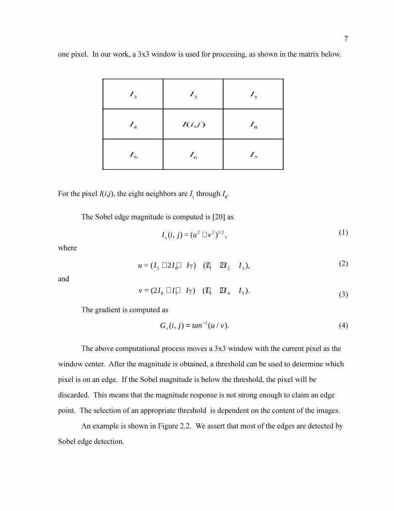
one pixel. In our work, a 3x3 window is used for processing, as shown in the matrix below.
For the pixel I(i,j), the eight neighbors are I1 through I
8.
The Sobel edge magnitude is computed is [20] as
(1)
where
(2)
and
(3)
The gradient is computed as
(4)
The above computational process moves a 3x3 window with the current pixel as the
window center. After the magnitude is obtained, a threshold can be used to determine which
pixel is on an edge. If the Sobel magnitude is below the threshold, the pixel will be
discarded. This means that the magnitude response is not strong enough to claim an edge
point. The selection of an appropriate threshold is dependent on the content of the images.
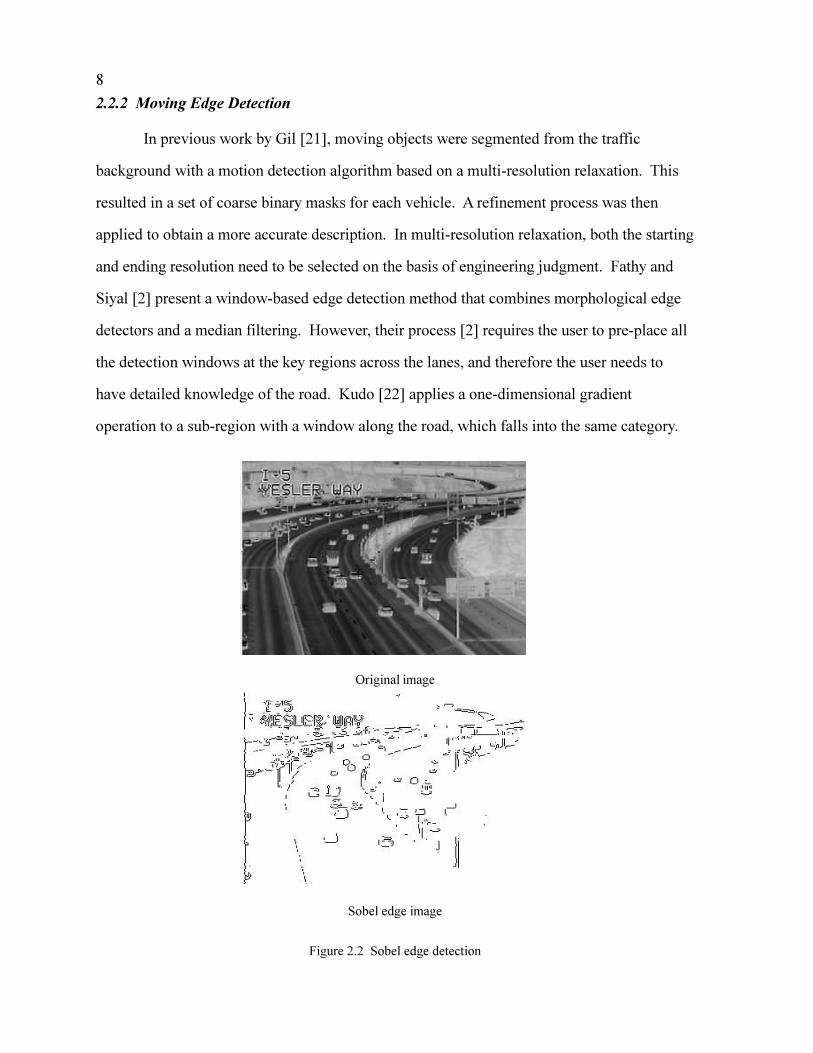
An example is shown in Figure 2.2. We assert that most of the edges are detected by
Sobel edge detection.
I3
I2
I1
I4
I(i,j) I8
I5
I6
I7
I i j u vs ( , ) = ( 2 2 1 2+ ) ,/
u I I I I I I= ( 5 6 7 1 2 32 2+ + − + +) ( ),
v I I I I I I= (2 8 1 7 3 4 52+ + − + +) ( ).
G i j tan u vs ( , ) ( / ).= −1
8
2.2.2 Moving Edge Detection
In previous work by Gil [21], moving objects were segmented from the traffic
background with a motion detection algorithm based on a multi-resolution relaxation. This
resulted in a set of coarse binary masks for each vehicle. A refinement process was then
applied to obtain a more accurate description. In multi-resolution relaxation, both the starting
and ending resolution need to be selected on the basis of engineering judgment. Fathy and
Siyal [2] present a window-based edge detection method that combines morphological edge
detectors and a median filtering. However, their process [2] requires the user to pre-place all
the detection windows at the key regions across the lanes, and therefore the user needs to
have detailed knowledge of the road. Kudo [22] applies a one-dimensional gradient
operation to a sub-region with a window along the road, which falls into the same category.
Original image
Sobel edge image
Figure 2.2 Sobel edge detection
9
In this process, we use image differencing to extract motion information. There are
two basic differencing methods in the literature: 1) background differencing and 2)
interframe differencing. In background differencing, a reference frame that contains no
moving vehicles is subtracted from each frame. In real world applications, where the
ambient lighting varies rapidly, the reference frame needs to be updated regularly to reflect
the current background and to provide reliable segmentation. This reference frame can be
obtained by either grabbing a frame when no vehicles are presented or by multi-frame
accumulation [23]. Several methods are suggested by Fathy and Siyal [2] and Koller et all
[17] to update the background image. However, these methods are slow and computationally
expensive and thus cannot meet real-time processing requirements. Furthermore, on
congested freeways (the domain of interest) it is difficult to obtain images with no vehicles
that match the present light level. Therefore, to mitigate these problems, we adopt the inter-
frame differencing method to eliminate the complex background and detect the moving
vehicles.
Cai [23] used forward and backward image differencing and then extracted common
regions corresponding to the moving areas. Instead of extracting regions, Vieren [24]
proposed a method to combine inter-frame differencing and a differential operator to extract
moving edges. In our process, we combine inter-frame differencing with the Sobel edge
detector to extract the moving edges. To emphasize the movement signature, we use three
sequential images and process each image relative to its previous and subsequent images. In
this way, we separate the movement from the static background.
Our algorithm is applied to three images: the previous temporal image (Ip), the
current image of interest (Ic), and the next temporal image (In):
(5)Edge image Sobel SobelI I I Ip c n c_ = − ∩ −( ) ( ) .
10
That is:
1) Take the difference between the previous image Ip and the
current image Ic.
2) Take the difference between the next image In and the
current image Ic.
3) Sobel edge operators are applied to these two different
images to get two edge images.
4) Compare the magnitudes of all edge pixels in the two edge
images resulting from the Sobel edge operator with a
magnitude threshold. If the magnitude of a pixel is less
than the threshold, then it is set to be 0. Otherwise, it
is set to be 1. This produces two binary edge images.
5) Create the intersection of the two binary edge images.
Extract common moving edges present in the original current
image, Ic.
This process produces an edge image for the current image of interest from which we
will extract individual vehicle information in the next chapter.
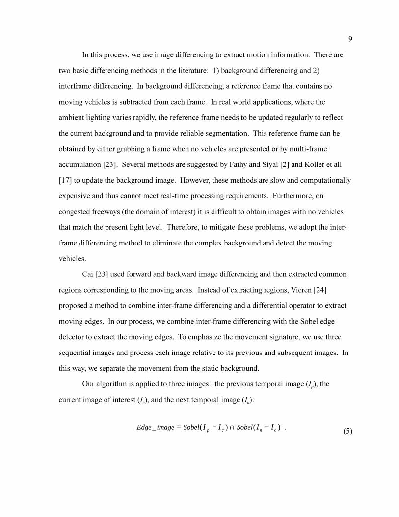
Figure 2.3 A typical sequence
11
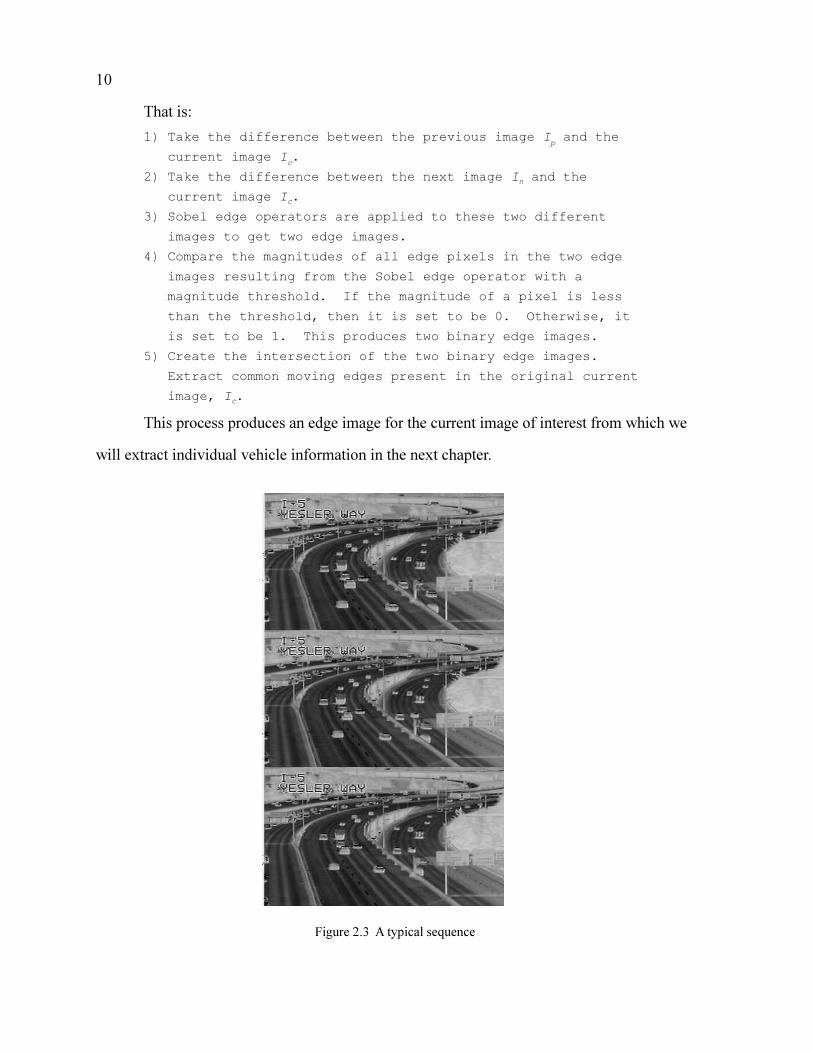
Example images for the above process are shown in Figures 2.3, 2.4, 2.5, and 2.6.
Figure 2.3 shows three original successive frames in an image sequence. Figure 2.4 shows
the edge image of the difference image between the first two frames. Figure 2.5 shows the
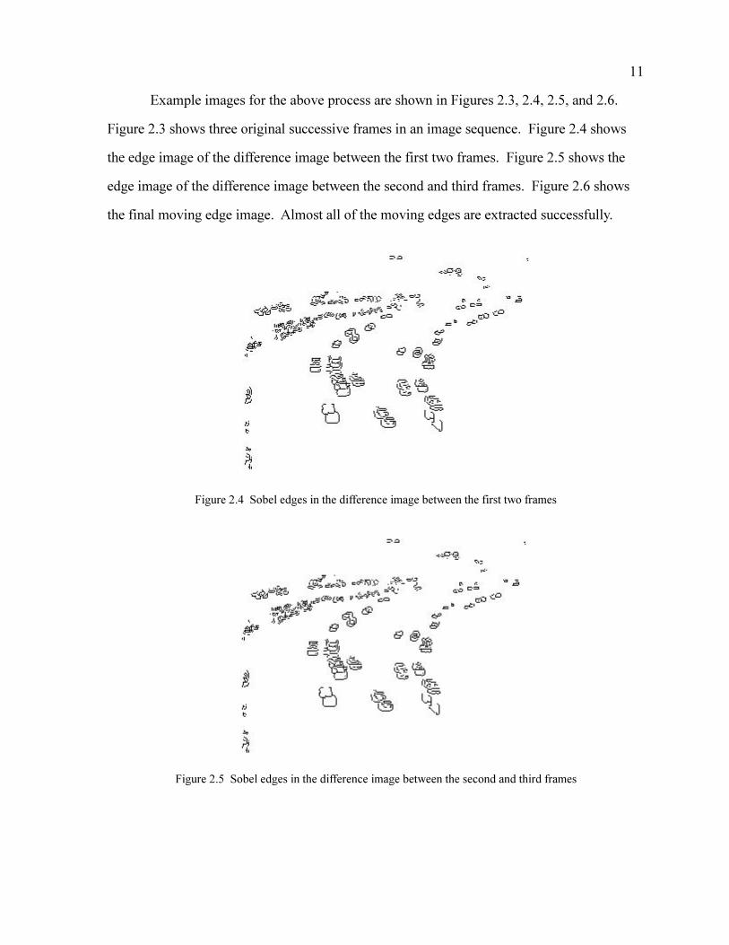
edge image of the difference image between the second and third frames. Figure 2.6 shows
the final moving edge image. Almost all of the moving edges are extracted successfully.
Figure 2.4 Sobel edges in the difference image between the first two frames
Figure 2.5 Sobel edges in the difference image between the second and third frames
12
Figure 2.6 Moving edges
2.3 MORPHOLOGICAL OPERATION TO OBTAIN MOVING BLOBS
In the moving edge image just described, there are always gaps along the edges. To
obtain a profile of the vehicle, we need to enhance the moving edges. This enhancement uses
the morphological operators dilation and erosion with an appropriate structural element. The
result of sequentially applying dilation and erosion [25] is to remove specific image features
smaller than the structural element without affecting the large features of interest.
Dilation and erosion are two basic morphological operations, which will be discussed
first. Dilating an object is to translate all its points with regard to a structural element
followed by union operation. On the other hand, eroding an object is to translate all its points
first by using a structural element and then to conduct the intersection operation to get the
final result. This way, dilation expands an object and erosion shrinks it by the size of the
specified structural element.
Images are dilated with the max operation. They are eroded with the min operation. A
structural element of N by N is used to define the max or min operation regions. To process
an image pixel, the region containing the pixel of interest and its (N-1) by (N-1) neighboring
pixels is processed, and the maximum or the minimum value is obtained.

13
That is, for an image matrix with m by n, and a given element size N,
1) sort the pixel values in the N by N neighborhood
2) put the maximum in the dilation image matrix
3) put the minimum in the erosion image matrix.
Since we are processing binary images, the above sorting process can be simplified to
test whether the pixel value is 1 or 0. In this way, the operations are very fast.
The selection of the size of the structural element N depends on the range of the size
of the vehicles of interest and the range of distance between the vehicles. For example, a
vehicle smaller than the structural element in the image will be removed by erosion. On the
other hand, several vehicles close to each other will be merged to a single blob after dilation.
While our goal is to extract as many vehicles as possible, we do not require every vehicle in
the image to be identified for our algorithm to accurately estimate speed. Using
morphological operations, some vehicles will be removed by erosion because of their small
size in the image (these have been deemed too small to be useful in speed estimation) or will
be merged by dilation because of their proximity (these have been deemed inappropriate
because of possible occlusion effects).
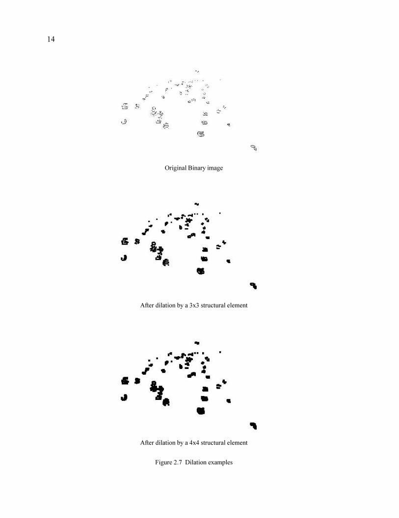
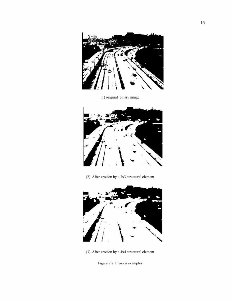
Figures 2.7 and 2.8 show some morphological examples. Figure 2.7 shows the result
of dilation operation. Different structural element sizes (3x3 and 4x4) are used. Observe that
dilation with larger sized structural elements will make some blobs merge together. Figure
2.8 shows erosion operations. Erosion with larger sized structural elements causes some
vehicles to disappear from the image.
14
Original Binary image
After dilation by a 3x3 structural element
After dilation by a 4x4 structural element
Figure 2.7 Dilation examples
15
(1) original binary image
(2) After erosion by a 3x3 structural element
(3) After erosion by a 4x4 structural element
Figure 2.8 Erosion examples
16
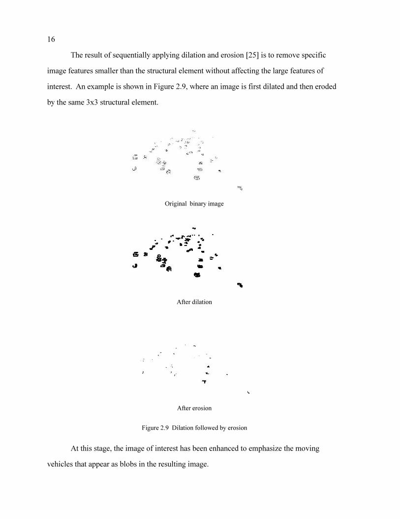
The result of sequentially applying dilation and erosion [25] is to remove specific
image features smaller than the structural element without affecting the large features of
interest. An example is shown in Figure 2.9, where an image is first dilated and then eroded
by the same 3x3 structural element.
Original binary image
After dilation
After erosion
Figure 2.9 Dilation followed by erosion
At this stage, the image of interest has been enhanced to emphasize the moving
vehicles that appear as blobs in the resulting image.
17
2.4 VEHICLE PROFILE APPROXIMATION
2.4.1 Convex Hull Extraction
After the application of morphological operators above, moving edges are filled and
appear as solid moving �blobs.� To characterize the blobs, we use a convex hull to
approximate the contour of the vehicles. In many cases, a convex hull is a good
approximation of the projection of a car [21, 17].
In the image produced by the procedure in the previous section, the background is full
of 0s, and only points inside and along the contours of the blob are of value 1. We select the
contour points by searching each scanline to find the rightmost or leftmost end of a blob.
Not all contour points selected by this method will belong to the convex hull.
Therefore, we need to select those points that are actually on the hull. Koller [17] proposed a
convex hull extraction method that is suitable for our purpose. The procedure is to define a
convex hull point, P2(x2,y2), by its location related to its preceding point, P1(x1,y1), and
following point P3(x3,y3). A threshold T is used to determine the associated orientation of
these three points, where
(6)
A positive value of T indicates that those three points are in counter-clockwise order
along the contour. A negative T value indicates that they are in clock-wise order.
This algorithm is used to efficiently obtain all the points on the convex hull, as shown
in the following description:
1) If contour point P2 is on the left side of the contour, T is
computed to check whether it is positive (counter-
clockwise). If so, P2 is regarded as being on the convex
hull. If not, P2 does not belong to the hull.
2) Similarly, if P2 is on the right side of the contour, T is
computed to check its sign. Now, contrary to the above
left-side case, if T is positive, it means P2 is not on the
T
x y
x y
x y
=1 1
2 2
3 3
1
1
1
.
18
convex hull. If T is negative (clockwise), P2 belongs to
the hull and should be retained.
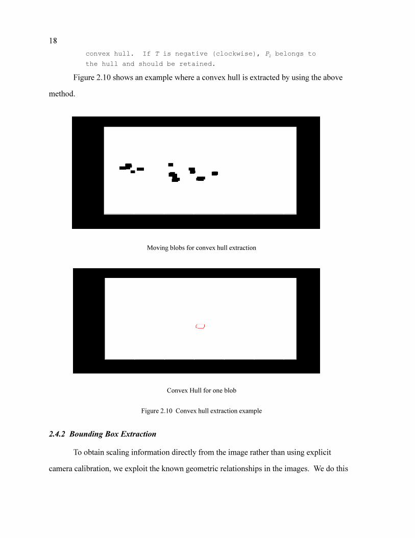
Figure 2.10 shows an example where a convex hull is extracted by using the above
method.
Moving blobs for convex hull extraction
Convex Hull for one blob
Figure 2.10 Convex hull extraction example
2.4.2 Bounding Box Extraction
To obtain scaling information directly from the image rather than using explicit
camera calibration, we exploit the known geometric relationships in the images. We do this
19
by constructing a bounding box to enclose the convex hull. This bounding box is used to
isolate the area of interest in the image and is similar to window (or key region) processing
described by Fathy and Siyal [26] and Stewart et al [27]. However, unlike window
processing, we are only interested in looking for some simple geometric relations inside the
box.
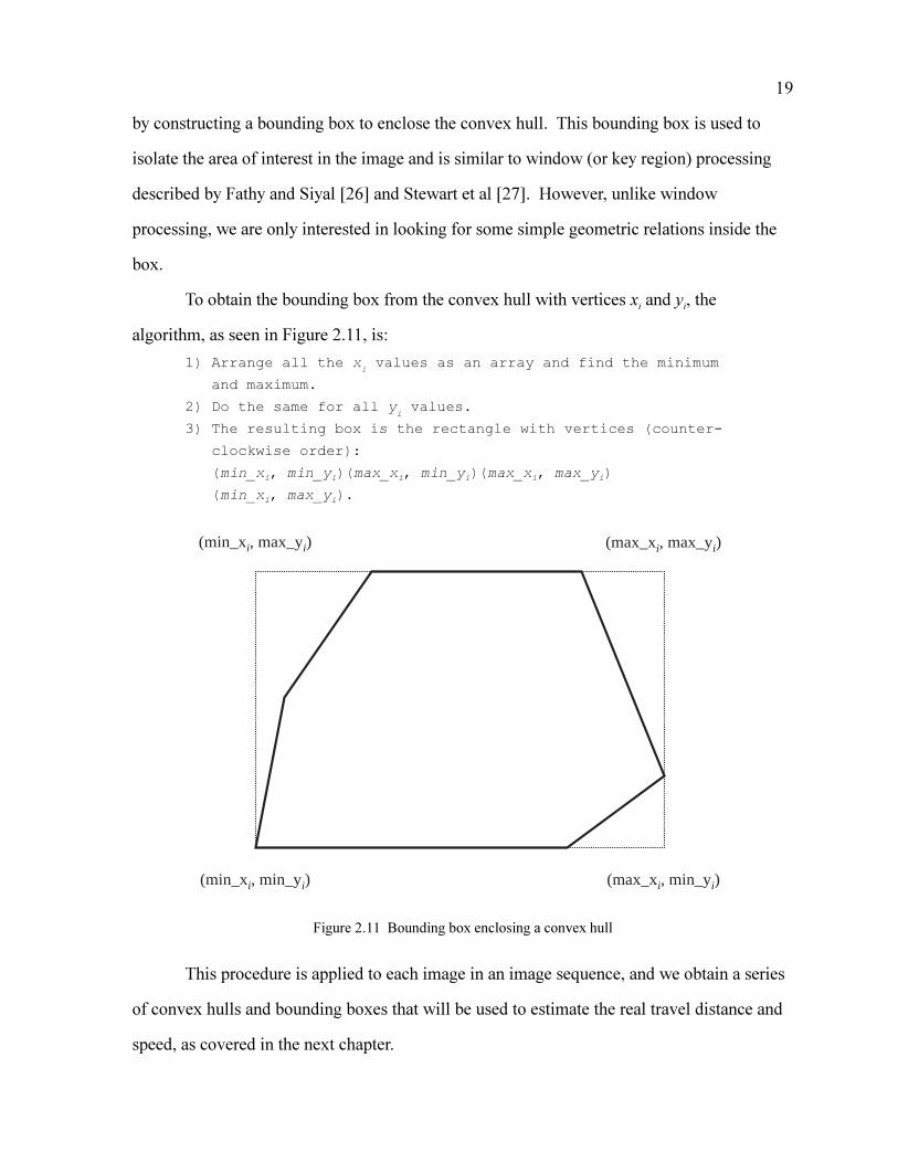
To obtain the bounding box from the convex hull with vertices xi and yi, the
algorithm, as seen in Figure 2.11, is:
1) Arrange all the xi values as an array and find the minimum
and maximum.
2) Do the same for all yi values.
3) The resulting box is the rectangle with vertices (counter-
clockwise order):
(min_xi, min_yi)(max_xi, min_yi)(max_xi, max_yi)
(min_xi, max_yi).
Figure 2.11 Bounding box enclosing a convex hull
This procedure is applied to each image in an image sequence, and we obtain a series
of convex hulls and bounding boxes that will be used to estimate the real travel distance and
speed, as covered in the next chapter.
(min_xi, max_yi)
(max_xi, min_yi)(min_xi, min_yi)
(max_xi, max_yi)

20
Figure 2.12 shows an example of extracting the bounding box from a convex hull.
Convex Hull for bounding box extraction
Bounding box extracted
Figure 2.12 Bounding box extraction
21
3 Geometric Analysis and Speed Estimation From an Image Sequence
The result from Chapter 2 is a series of convex hulls and bounding boxes. This
chapter describes utilizing the geometric features and this series of hulls and blobs for
distance and speed computation.
To estimate speed, we first obtain the direction of motion of each vehicle and then
compute the best fit line through the centroids of the convex hulls found in a series of images
and associated with a single vehicle. A threshold on the correlation coefficient [28] for the
centroids is used as the colinearity criterion to identify a single vehicle track. The best fit line
for the direction of travel is used to obtain the pixel length of the vehicle, and we exploit a
simple triangular relationship in the bounding box to get the pixel length of the vehicle,
which is then used to compute the scale information in the images. Ground truth distance is
estimated by using scale information along the direction of motion, and these distances, with
the frame rate of the video sequence, are used to estimate speed.
3.1 DIRECTION OF MOTION:
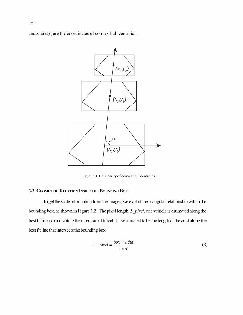
We assume that the vehicles make no sudden changes in directions between
successive video frames. This assumption allows us to track individual vehicles through
successive frames. We identify a single vehicle track by requiring that the centroids of the
convex hull be colinear in successive frames, as shown in Figure 3.1. The linear regression
correlation coefficient r for least square straight line fitting, as presented by Bevington [28],
is the criterion for determining the colinearity of centroids.
From experiments, we claim that we are able to identify a single vehicle in a
succession of images if the colinearity of the centroids produces a linear regression
correlation coefficient r greater than 0.90, where
(7)rn x y x y
n x x n y y
i i ii
n
ii
n
i
n
ii
n
ii
n
i ii
n
i
n
=−
−
−
− −−
− − −−
∑ ∑∑
∑ ∑ ∑∑
1 11
2
1 1
2
2
1
2
1
,
22
and xi and y
i are the coordinates of convex hull centroids.
Figure 3.1 Colinearity of convex hull centroids
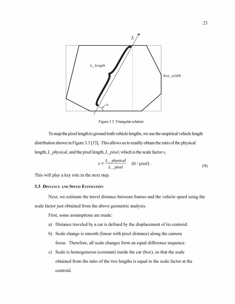
3.2 GEOMETRIC RELATION INSIDE THE BOUNDING BOX
To get the scale information from the images, we exploit the triangular relationship within the
bounding box, as shown in Figure 3.2. The pixel length, L_pixel, of a vehicle is estimated along the
best fit line (L) indicating the direction of travel. It is estimated to be the length of the cord along the
best fit line that intersects the bounding box.
(8)
(x3,y3)
(x2,y2)
(x1,y1)
L pixelbox width
__
.=sinα
23
Figure 3.2 Triangular relation
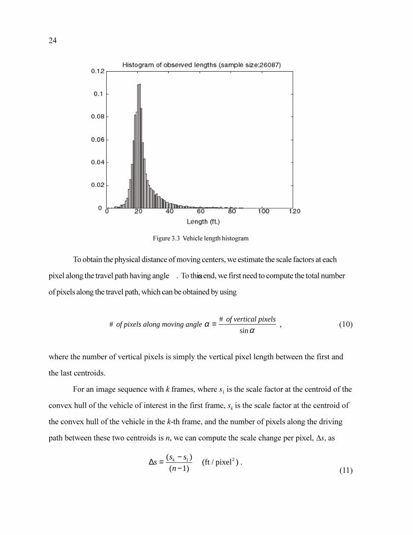
To map the pixel length to ground truth vehicle lengths, we use the empirical vehicle length
distribution shown in Figure 3.3 [15]. This allows us to readily obtain the ratio of the physical
length, L_physical, and the pixel length, L_pixel, which is the scale factor s,
(9)
This will play a key role in the next step.
3.3 DISTANCE AND SPEED ESTIMATION
Next, we estimate the travel distance between frames and the vehicle speed using the
scale factor just obtained from the above geometric analysis.
First, some assumptions are made:
a) Distance traveled by a car is defined by the displacement of its centroid.
b) Scale change is smooth (linear with pixel distance) along the camera
focus. Therefore, all scale changes form an equal difference sequence.
c) Scale is homogeneous (constant) inside the car (box), so that the scale
obtained from the ratio of the two lengths is equal to the scale factor at the
centroid.
L
box_width
L_length{s
lL physica
L pixel= _
_ft pixel ( / ) .
24
Figure 3.3 Vehicle length histogram
To obtain the physical distance of moving centers, we estimate the scale factors at each
pixel along the travel path having angle . To this end, we first need to compute the total number
of pixels along the travel path, which can be obtained by using
(10)
where the number of vertical pixels is simply the vertical pixel length between the first and
the last centroids.
For an image sequence with k frames, where s1 is the scale factor at the centroid of the
convex hull of the vehicle of interest in the first frame, sk is the scale factor at the centroid of
the convex hull of the vehicle in the k-th frame, and the number of pixels along the driving
path between these two centroids is n, we can compute the scale change per pixel, Ds, as
(11)
# #
,of pixels along moving angleof vertical pixelsα
α=
sin
∆ss s
nk= −
−( )
( )1
1 (ft / pixel ) .2
25
The total distance D traversed between the images is then obtained by summing up the scale factor
series as
(12)
The speed is then estimated as the ratio of the interframe travel distance and the known frame
rate.
The material just presented is the first published algorithm for an estimate of single
vehicle speed using a statistical vehicle length and an uncalibrated camera. The algorithm
creates scale information on the fly from information contained in the image and does not
require calibration markers in the physical environment.
The algorithm presented here is validated against ground truth measurements in the
next chapter.
D nsn n
s
ns sk
= + −
( )1
1
1
2
2
( ) ∆ ( )
=+
ft

26
27
4 Field Trials and Discussions
4.1 FIELD TRIALS METHODOLOGY
To test our algorithm, we compared the distance estimates (called estimated distance)
obtained with our dynamic calibration technique with ground truth measurements on the
freeway. Because the travel time interval is set by the inter-frame time, the only unknown is
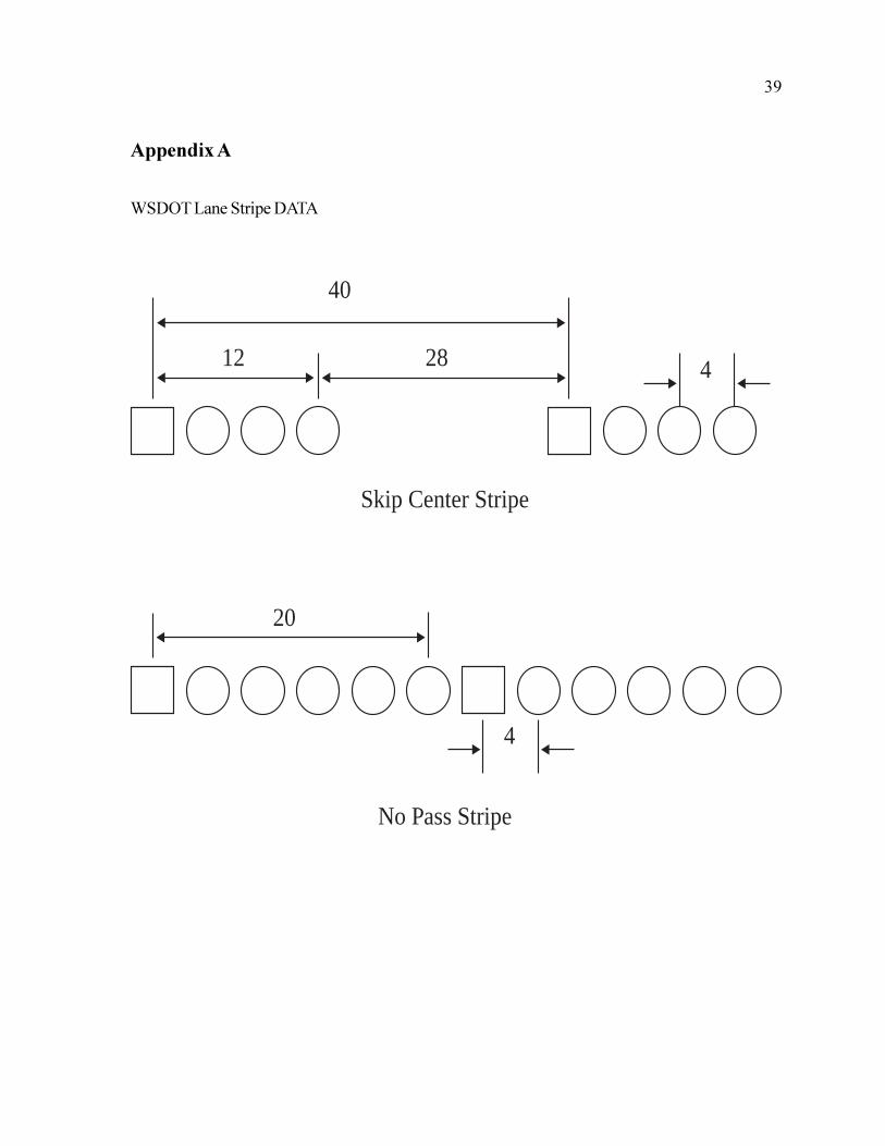
the ground truth travel distance. Field trials used both the distance between and the size of
the center stripes. Both these measurements are published by WSDOT, as seen in Appendix
A.
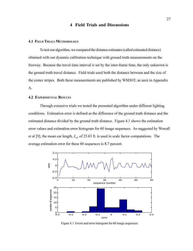
4.2 EXPERIMENTAL RESULTS
Through extensive trials we tested the presented algorithm under different lighting
conditions. Estimation error is defined as the difference of the ground truth distance and the
estimated distance divided by the ground truth distance. Figure 4.1 shows the estimation
error values and estimation error histogram for 60 image sequences. As suggested by Worrall
et al [9], the mean car length, Lm, of 25.63 ft. is used in scale factor computations. The
average estimation error for these 60 sequences is 8.7 percent.
Figure 4.1 Errors and error histogram for 60 image sequences
0 10 20 30 40 50 60-0.4
-0.2
0
0.2
0.4
sequence number
erro
r
-0.4 -0.3 -0.2 -0.1 0 0.1 0.2 0.30
5
10
15
20
25
error
num
ber of
seq
uenc
es
28
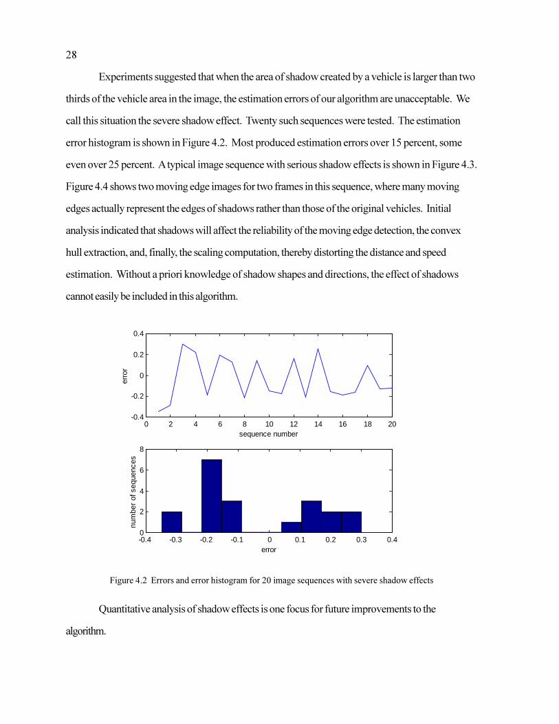
Experiments suggested that when the area of shadow created by a vehicle is larger than two
thirds of the vehicle area in the image, the estimation errors of our algorithm are unacceptable. We
call this situation the severe shadow effect. Twenty such sequences were tested. The estimation
error histogram is shown in Figure 4.2. Most produced estimation errors over 15 percent, some
even over 25 percent. A typical image sequence with serious shadow effects is shown in Figure 4.3.
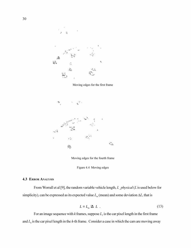
Figure 4.4 shows two moving edge images for two frames in this sequence, where many moving
edges actually represent the edges of shadows rather than those of the original vehicles. Initial
analysis indicated that shadows will affect the reliability of the moving edge detection, the convex
hull extraction, and, finally, the scaling computation, thereby distorting the distance and speed
estimation. Without a priori knowledge of shadow shapes and directions, the effect of shadows
cannot easily be included in this algorithm.
Figure 4.2 Errors and error histogram for 20 image sequences with severe shadow effects
Quantitative analysis of shadow effects is one focus for future improvements to the
algorithm.
0 2 4 6 8 10 12 14 16 18 20-0.4
-0.2
0
0.2
0.4
sequence number
erro
r
-0.4 -0.3 -0.2 -0.1 0 0.1 0.2 0.3 0.40
2
4
6
8
error
num
ber
of s
eque
nces

29
Figure 4.3 A typical sequence with severe shadow effects
first frame
second frame
third frame
fourth frame
30
Moving edges for the first frame
Moving edges for the fourth frame
Figure 4.4 Moving edges
4.3 ERROR ANALYSIS
From Worrall et al [9], the random variable vehicle length, L_physical (L is used below for
simplicity), can be expressed as its expected value Lm (mean) and some deviation DL, that is
(13)
For an image sequence with k frames, suppose L1 is the car pixel length in the first frame
and Lk is the car pixel length in the k-th frame. Consider a case in which the cars are moving away
L L Lm= + ∆ .

31
from the camera, so that the scale factor increases with the distance from the camera. (The analysis
is similar for a case in which the cars are moving toward the camera.) Combining equations (9) and
(12) gives us the estimated distance Dm,
(14)
Considering length deviation in equation (13) gives us the deviated distance Dde as
(15)
Let e be the absolute error of distance measurement, and thus e = Dde - Dm. Combining
equations (14) and (15) gives the mean of error e,
(16)
where E{*} is the expected value operator, and the variance, Var{e}, is
(17)
Equations (16) and (17) reveal that the length deviation (L) directly affects the
measurement error, since the pixel number n and pixel lengths Lk and L1 are uniquely
determined for a specific image sequence with k frames.
4.4 POSSIBLE SYSTEM EXTENSIONS
The speed information obtained from this work can be used directly for many applications,
such as traffic congestion detection. It is also worthwhile to note that with some modifications, our
method can be readily extended to other traffic analysis, including incident detection, traffic model
verification, and travel time estimation. The techniques introduced in this report can be used as a
Dn L
L
L
L
Ln
L L
mm m
k
mk
= +
= +
2
2
1 11
1
( )
( )
D L Ln
L Lde mk
= + +( ) ( ).∆2
1 1
1
E en
L LE L
k
{ } ( ) { },= +2
1 1
1
∆
Var en
L LVar L
k
{ } [ ( )] { }.= +2
1 1
1
2 ∆

32
basis for developing general-purpose, advanced intelligent traffic surveillance systems. For
example, combined with character pattern recognition process, our method can be extended to
recognize the vehicle license plate number, which has recently become an active research area.

33
5 Conclusion
There are many challenging problems in studying real traffic scenes within a complex
background. In this report, efficient image processing techniques are applied to traffic analysis to
estimate travel speed from image sequences of moving vehicles. Simple geometric relations are
obtained directly from the image itself and are used to deal with real-world problems without explicit
camera calibration. Furthermore, the techniques presented are validated against ground truth by
field trials. Error analysis is also given in detail. The car length distribution is shown to be a key
factor in the accuracy of speed sensing.
Some problems remain to be solved, including the effect of shadows and occlusion of
vehicles.
As a result of the work presented here, a manuscript has been submitted to the IEEE
Intelligent Transportation Systems Council for presentation at ITSC�99, a peer reviewed
conference. A copy of this manuscript appears in Appendix B.

34

35
References
1. Kilger, M. Video-Based Traffic Monitoring. International Conference on Image Processingand its Applications, 7-9 April 1992, Maastricht, Netherlands, pp. 89-92.
2. Fathy, M. and M.Y. Siyal. An Image Detection Technique Based on Morphological EdgeDetection and Background Differencing for Real-Time Traffic Analysis. PatternRecognition Letters, Vol. 16, No. 12, December 1995, pp. 1321-1330.
3. Hoose, N. and L.G. Willumsen. Automatically Extracting Traffic Data From VideotapeUsing The CLIP4 Parallel Image Processor. Pattern Recognition Letters, Vol. 6,No. 3, August 1987, pp. 199-213.
4. Ali, A.T. and E.L. Dagless. Computer Vision for Automatic Road Traffic Analysis.ICARCV 90, Proceedings of the International Conference on Automation,Robotics and Computer Vision, 19-21 September 1990, pp. 875-879.
5. Fathy, M. and M.Y.Siyal, Real-Time Image Processing Approach to Measure TrafficQueue Parameters. IEE Proceedings - Vision, Image and Signal Processing,Vol.142, No.5, October 1995, pp. 297-303.
6. Soh, J., B.T. Chun, and M. Wang. Analysis of Road Sequences for Vehicle Counting.1995 IEEE International Conference on Systems, Man and Cybernetics, Vol.1, 22-25 October 1995, Vancouver, British Columbia, Canada, pp. 679-683.
7. Zifeng, J. Macro and Micro Freeway Automatic Incident Detection(Aid) Methods Basedon Image Processing. IEEE Conference on Intelligent Transportation Systems, 9-12 November 1997, Boston, Massachusetts, USA, pp.344-349.
8. Picton, P.D. Tracking and Segmentation of Moving Objects in a Scene. ThirdInternational Conference on Image Processing and its Applications (Conf. Publ.No.307), 18-20 July 1989, Warwick, UK, pp. 389-393.
9. Worrall, A.D., G.D. Sullivan, and K.D. Baker. A Simple, Intuitive Camera CalibrationTool for Natural Images. Proceedings of the 5th British Machine VisionConference, 13-16 September 1994, York, UK, pp. 781-790.
10. Dickinson, K.W. and R.C. Waterfall. Video Image Processing for Monitoring RoadTraffic. IEE International Conference on Road Traffic Data Collection, 5-7December 1984, pp. 105-109.
11. Ashworth, R., D.G. Darkin, K.W. Dickinson, M.G. Hartley, C.L. Wan, and R.C.Waterfall. Applications of Video Image Processing for Traffic Control Systems.Second International Conference on Road Traffic Control, 14-18 April 1985,London, UK, pp. 119-122.
36
12. Takaba, S., M. Sakauchi, T. Kaneko, B. Won-Hwang, and T. Sekine. Measurement of TrafficFlow Using Real Time Processing of Moving Pictures. 32nd IEEE VehicularTechnology Conference, 23-26 May 1982, San Diego, California, USA, pp. 488-494.
13. Hashimoto, N., Y. Kumagai, K. Sakai, K. Sugimoto, Y. Ito, K. Sawai, and K. Nishiyama.Development of an Image-Processing Traffic Flow Measuring System. SumitomoElectric Technical Review, No. 25, January 1986, pp. 133-137.
14. Houkes, Z. Measurement of Speed and Time Headway of Motor Vehicles with VideoCamera and Computer. Proceedings of the 6th IFAC/IFIP Conference on DigitalComputer Applications to Process Control, 14-17 October 1980, Dusseldorf, WestGermany, pp. 231-237.
15. Dailey, D.J. A Statistical Algorithm for Estimating Speed from Single Loop Volume andOccupancy Measurements. Transportation Research B, Vol. 33B, No. 5, June1999, pp. 313-22.
16. Hoose, N. and L.G. Willumsen Real Time Vehicle Tracking Using the CLIP4 ParallelProcessor. Seminar on Information Technology in Traffic and Transport. PTRC.Summer Annual Meeting, University of Bath, UK, 1987, pp. 113-131.
17. Koller, D., J. Weber, and J. Malik. Robust Multiple Car Tracking with OcclusionReasoning, Report No. UCB/CSD 93/780, Computer Science Division (EECS)UC-Berkeley, 22 November 1993
18. Pratt, William K. Digital Image Processing, 2nd Ed. John Wiley and Sons. Inc., NewYork, c1991.
19. Davies, E.R. Machine Vision: Theory, Algorithms, Practicalities. 2nd Edition.Academic Press, London, England, 1997.
20. Ritter, Gerhard X. and Joseph N. Wilson. Handbook of Computer Vision Algorithms inImage Algebra. CRC Press, Boca Raton, Florida, 1996.
21. Gil, S., R. Milanese, and T. Pun. Comparing Features for Target Tracking in TrafficScenes. Pattern Recognition, Vol. 29, No. 8, August 1996, pp. 1285-1296.
22. Kudo, Y., T. Yamahira, T. Tsurutani, and M. Naniwada. Traffic Flow MeasurementSystem Using Image Processing. 33rd IEEE Vehicular Technology Conference,Toronto, 25-27 May 1983, Ontario, Canada, pp. 28-34.
23. Cai, Q., A. Mitiche, and J.K. Aggarwal. Tracking Human Motion in an IndoorEnvironment. International Conference on Image Processing, 23-26 October1995, Washington, D.C., USA, Vol. 1, pp. 215-218.

37
24. Vieren, C., F. Cabestaing, and J.G. Postaire. Catching Moving Objects with Snakes forMotion Tracking. Pattern Recognition Letters, Vol. 16, No. 7, July 1995, pp. 679-685.
25. Serra, Jean Paul. Image Analysis and Mathematical Morphology. Academic Press,London, New York, 1982.
26. Fathy, M. and M.Y. Siyal. A Window-Based Edge Detection Technique for MeasuringRoad Traffic Parameters in Real-Time. Real-Time Imaging, Vol. 1, No. 4, October1995, pp. 297-305.
27. Stewart, B.D., I.A.D. Reading, M.S. Thomson, C.L. Wan, and T.D. Binnie. DirectingAttention for Traffic Scene Analysis. Fifth International Conference on ImageProcessing and its Applications, 4-6 July 1995, Edinburgh, UK, pp. 801-805.
28. Bevington, Philip R. Data Reduction and Error Analysis for the Physical Sciences.McGraw-Hill Book Company, New York, 1969.

38
39
Appendix A
WSDOT Lane Stripe DATA
12 28
40
4
4
20
Skip Center Stripe
No Pass Stripe

40

41
Appendix B
Copy of manuscript submitted to IEEE Intelligent Transportation Systems Council for
presentation at ITSC�99.
$Q $OJRULWKP WR (VWLPDWH 9HKLFOH 6SHHG 8VLQJ 8Q�&DOLEUDWHG&DPHUDV
'�-� 'DLOH\� /� /L'HSDUWPHQW RI (OHFWULFDO (QJLQHHULQJ
8QLYHULVW\ RI :DVKLQJWRQ6HDWWOH� :DVKLQJWRQ� �����
$EVWUDFW,Q WKLV SDSHU ZH SUHVHQW D QHZ DOJRULWKP WR HVWL�
PDWH VSHHG XVLQJ D VHTXHQFH RI YLGHR LPDJHV IURP DQXQ�FDOLEUDWHG FDPHUD� 7KH DOJRULWKP XVHV IUDPH GLI�IHUHQFLQJ WR LVRODWH PRYLQJ HGJHV DQG WUDFN YHKLFOHVEHWZHHQ IUDPHV� 7KH DOJRULWKP XVHV D NQRZQ YHKLFOHOHQJWK GLVWULEXWLRQ ZLWK LPDJH LQIRUPDWLRQ WR HVWLPDWHVSHHG�
� ,QWURGXFWLRQ,PDJH SURFHVVLQJ WHFKQLTXHV KDYH EHHQ DSSOLHG WR
WUD�F VFHQHV IRU D YDULHW\ RI SXUSRVHV LQFOXGLQJ� TXHXHGHWHFWLRQ� LQFLGHQW GHWHFWLRQ� YHKLFOH FODVVL�FDWLRQ�DQG YHKLFOH FRXQWLQJ >�� �� �� �� �� �@� ,Q WKLV SDSHU�ZH SUHVHQW D QHZ DOJRULWKP WR HVWLPDWH VSHHG XVLQJ DVHTXHQFH RI YLGHR LPDJHV IURP DQ XQ�FDOLEUDWHG FDP�HUD� 7KLV ZRUN LV PRWLYDWHG E\ WKH ODUJH QXPEHU RIURDGVLGH FDPHUDV LQVWDOOHG E\ '27V WR REVHUYH WUD�F�7KH FDPHUDV DUH W\SLFDOO\ QRW LQVWDOOHG LQ D PDQQHUWKDW WKH\ FDQ HDVLO\ EH FDOLEUDWHG� DQG WKH\ DUH W\S�LFDOO\ XVHG E\ RSHUDWRUV ZKR FDQ WLOW� SDQ� DQG ]RRPXVLQJ D MR\VWLFN WR FKDQJH WKH FDPHUD FDOLEUDWLRQ� 7KHFRPELQDWLRQ RI PRYDEOH FDPHUDV DQG ODFN RI FDOLEUD�WLRQ PDNHV HVWLPDWLQJ VSHHG IRU XQ�FDOLEUDWHG FDPHUDVD FKDOOHQJH�5HODWLYHO\ IHZ H�RUWV KDYH EHHQ PDGH WR PHDVXUH
VSHHG XVLQJ YLGHR LPDJHV IURP XQ�FDOLEUDWHG FDPHUDV�6RPH SUHOLPLQDU\ UHVHDUFK RQ SL[HO VSHHG HVWLPDWLRQLQ LPDJHV DSSHDUV LQ >�@� ,Q SUHYLRXV ZRUN IHZ H�RUWVZHUH PDGH WR PDS SL[HO VSHHG WR JURXQG WUXWK VSHHG�$ UHYLHZ RI WKH OLWHUDWXUH RQ VSHHG HVWLPDWLRQ XVLQJFDPHUDV LQGLFDWHV WKDW PRVW DOJRULWKPV HLWKHU XVH UHI�HUHQFH LQIRUPDWLRQ LQ WKH VFHQH RU FUHDWH VXFK UHIHU�HQFHV LQWHUDFWLYHO\� )RU H[DPSOH� :RUUDOO >�@ UHSRUWVDQ LQWHUDFWLYH WRRO WR SHUIRUP FDPHUD FDOLEUDWLRQ LQZKLFK DQ RSHUDWRU XVHV SDUDOOHO URDG PDUNV WR LGHQWLI\YDQLVKLQJ SRLQWV DQG WKHQ SODFHV D UHFWDQJXODU FDOLEUD�WLRQ JULG RQ WKH LPDJH� )XUWKHU� LQ >�@ DQG >�@� VSHHGPHDVXUHPHQWV DUH PDGH XVLQJ WKH NQRZQ SK\VLFDO GLV�WDQFH EHWZHHQ WZR GHWHFWLRQ ZLQGRZV SODFHG RQ WKH
URDG LPDJH E\ DQ RSHUDWRU� 6LPLODUO\� VHYHUDO RWKHUDXWKRUV >��� ��@ VXJJHVW HVWLPDWLQJ VSHHG E\ SODFLQJWZR GHWHFWLRQ OLQHV� RI NQRZQ VHSDUDWLRQ� LQ WKH LP�DJH DQG PHDVXULQJ WUDYHO WLPHV EHWZHHQ WKH OLQHV� ,QDGGLWLRQ� +RXNHV >��@ VXJJHVW WKH VHOHFWLRQ RI � UHIHU�HQFH SRLQWV IRUPLQJ D UHFWDQJOH DQG SHUIRUPLQJ R��OLQHPHDVXUHPHQWV� $OO WKHVH PHWKRGV UHTXLUH WKH RSHUD�WRU WR SHUIRUP D FDOLEUDWLRQ SURFHGXUH EHIRUH VSHHGHVWLPDWLRQ FDQ EH XQGHUWDNHQ�
,Q WKLV SDSHU� LW LV DVVXPHG WKDW ZH KDYH QR FRQWURORYHU FDPHUD PRYHPHQWV� DQG WKXV FDQQRW GLUHFWO\ RE�WDLQ LQIRUPDWLRQ VXFK DV FDPHUD IRFXV� WLOW� RU DQJOH�,W LV IXUWKHU DVVXPHG WKDW WKH FDPHUD SDUDPHWHUV FDQFKDQJH ZLWK WLPH� ,Q WKH ZRUN SUHVHQWHG KHUH� ZH DUHPRQLWRULQJ FRQJHVWHG IUHHZD\V DQG KDYH QHLWKHU WKHDELOLW\ QRU WKH DXWKRULW\ WR VHW SHUPDQHQW PDUNV RQWKH URDG� *LYHQ WKLV VFHQDULR� ZH EHOLHYH RQ�OLQH FDO�LEUDWLRQ LV D QHFHVVDU\ VWHS WR HQDEOH WKH XVH RI WKHODUJH� LQVWDOOHG EDVH RI 706 FDPHUDV�
:H DVVHUW WKDW H[DFW FDOLEUDWLRQ LV QRW QHFHVVDU\ WRHVWLPDWH VSHHG� ,QVWHDG� ZH XVH� ��� JHRPHWULF UHOD�WLRQVKLSV LQKHUHQWO\ DYDLODEOH LQ WKH LPDJH� ��� VRPHFRPPRQ VHQVH DVVXPSWLRQV �OLVWHG EHORZ� WKDW UHGXFHWKH SUREOHP WR D ��' JHRPHWU\� DQG ��� WKH GLVWULEX�WLRQ RI YHKLFOH OHQJWKV� WR SURSRVH D QRYHO PHWKRG WKDWH[WUDFWV VFDOH LQIRUPDWLRQ DQG HVWLPDWHV VSHHG�
7R GHVFULEH DQG GHPRQVWUDWH RXU VSHHG HVWLPDWLRQVFKHPH� ZH �UVW UHYLHZ WKH DVVXPSWLRQV PDGH LQ IRU�PXODWLQJ WKH DOJRULWKP� :H WKHQ HQXPHUDWH WKH VWHSVRI WKH DOJRULWKP� IROORZHG E\ D GLVFXVVLRQ RI WKH LQ�GLYLGXDO VWHSV� )LQDOO\ ZH SUHVHQW VRPH SUHOLPLQDU\TXDQWLWDWLYH UHVXOWV RI WKH DOJRULWKP�
� 8QGHUO\LQJ $VVXPSWLRQV7R FUHDWH DQ DOJRULWKP WR HVWLPDWH VSHHG IURP YLGHR
LPDJHV ZH PDNH VHYHUDO DVVXPSWLRQV WR VLPSOLI\ WKHSUREOHP�
�� 7KH VSHHG RI WKH YHKLFOHV LV �QLWH� 7KH VSHHG RID YHKLFOH KDV ERWK SK\VLFDO DQG OHJDO OLPLWV�

�� 7KH YHKLFOH PRYHPHQW LV VPRRWK� 7KHUH DUH QRVXGGHQ FKDQJHV RI GLUHFWLRQ LQ WKH WLPH LQWHUYDO����PV� EHWZHHQ IUDPHV LQ WKH LPDJH VHTXHQFH�
�� 0RWLRQ LV FRQVWUDLQHG WR WKH URDG SODQH� 7UDFNLQJRI YHKLFOHV LQ WKH LPDJH VHTXHQFH LV D RQH GLPHQ�VLRQDO SUREOHP�
�� 7KH VFDOH IDFWRU �IHHW SHU SL[HO� YDULHV OLQHDUO\DORQJ WKH GLUHFWLRQ RI YHKLFOH WUDYHO� 7KLV DVVXPS�WLRQ FRQVWUDLQV WKH YHKLFOHV WR EH PRYLQJ JHQHU�DOO\ WRZDUG RU JHQHUDOO\ DZD\ IURP WKH FDPHUD�
�� 7KH OHQJWKV RI WKH YHKLFOHV LQ WKH LPDJHV DUH UHDO�L]DWLRQV IURP D NQRZQ YHKLFOH OHQJWK GLVWULEXWLRQ�
:LWK WKHVH DVVXPSWLRQV� WKH YHKLFOHV DUH WUHDWHG DVWKRXJK WKH\ WUDYHO LQ RQH GLPHQVLRQ DORQJ D VWUDLJKWOLQH LQ WKH LPDJH� 7KH YHKLFOHV DUH WUDFNHG DFURVV WKHVHLPDJHV WR REWDLQ VFDOH IDFWRUV WKDW HVWLPDWH WKH UHDO�ZRUOG GLVWDQFH UHSUHVHQWHG E\ SL[HOV DW YDULRXV ORFD�WLRQV LQ WKH LPDJH� 8VLQJ D OLQHDU IXQFWLRQ WR �W WRWKH HPSLULFDO VFDOH IDFWRUV LW LV SRVVLEOH WR HVWLPDWHWKH UHDO�ZRUOG GLVWDQFH WUDYHOHG� &RPELQLQJ WKH GLV�WDQFH WUDYHOHG ZLWK WKH NQRZQ IUDPH UDWH DOORZV XV WRHVWLPDWH VSHHG� $Q DOJRULWKP WR SHUIRUP WKLV HVWLPD�WLRQ LV SUHVHQWHG LQ WKH QH[W VHFWLRQ�
� 7KH $OJRULWKP7KH DOJRULWKP RSHUDWHV RQ D VHULHV RI DW OHDVW �YH VH�
TXHQWLDO LPDJHV� 7KH LQQHU ORRS RSHUDWHV RQ VHTXHQWLDOJURXSV RI WKUHH LPDJHV WR FUHDWH RQH HQKDQFHG LPDJH�7KH RXWHU ORRS XVHV D VHTXHQFH RI HQKDQFHG LPDJHV WRHVWLPDWH VSHHG�
2XWHU /RRS
�� 2EWDLQ �YH RU PRUH VHTXHQWLDO LPDJHV ����[�����JUD\ VFDOH DW WKUHH IUDPHV SHU VHFRQG �H�J�>,L� ,L��� ,L��� ,L��� ,L��� ���� ,L�1 @ ZKHUH 1 � ��
�� &UHDWH VHWV RI WKUHH VHTXHQWLDO LPDJHV�H�J� >,L� ,L��� ,L��@ LV WKH LWK VHW RI �1 � �� VHWV�
,QQHU /RRS
)RU HDFK RI WKH VHWV RI WKUHH VHTXHQWLDO YLGHRLPDJHV� SHUIRUP WKH IROORZLQJ�
�D� 0HGLDQ �OWHU HDFK LPDJH�
�E� 'L�HUHQFH WKH �UVW DQG VHFRQG LPDJHV ��,L�,L���� DV ZHOO DV WKH WKLUG DQG VHFRQG LPDJHV�,L�� � ,L���� WR JHW WZR GL�HUHQFH LPDJHV�
�F� $SSO\ D 6REHO HGJH GHWHFWRU WR WKH GL�HUHQFHLPDJHV WR REWDLQ HGJH LPDJHV 6REHO�,L�� �,L��� DQG 6REHO�,L � ,L��� �
�G� 7KUHVKROG WKH HGJH LPDJHV WR FUHDWH ELQDU\LPDJHV�
�H� ,QWHUVHFW WKH WZR ELQDU\ LPDJHV WR REWDLQ WKHPRYLQJ HGJH LPDJH �0(�,L���� IRU WKH ,L��LPDJH�
0(�,L��� 7KUHVKROG�6REHO�,L�� � ,L����
? 7KUHVKROG�6REHO�,L � ,L�����
�I� $SSO\ GLODWLRQ WR WKH PRYLQJ HGJH LPDJH�
�J� $SSO\ HURVLRQ WR WKH PRYLQJ HGJH LPDJH�
�K� ,GHQWLI\ WKH VHW RI SRLQWV &M�,L��� IRU WKHM FRQYH[ KXOOV LQ WKH PRYLQJ HGJH LPDJH0(�,L����
�L� &DOFXODWH FHQWURLG ��L��� M� �[� \� IRU WKHMWK FRQYH[ KXOO LQ LPDJH ,L���
�M� &DOFXODWH WKH VHW RI SRLQWV IRU WKH ERXQGLQJER[HV %M�,L��� IRU WKH M FRQYH[ KXOOV�
(QG RI WKH LQQHU ORRS
�� 6HOHFW VHWV RI FR�OLQHDU FHQWURLGV >��L� �� M�� ��L��� M�� ��L � �� M�� ��� ��1 � �� M�@ LQ VHTXHQWLDOLPDJHV DQG HVWLPDWH D EHVW �W OLQH WKURXJK WKHVHSRLQWV� 7KH VORSH RI WKLV OLQH LV WKH WDQJHQW RIWKH DQJOH RI PRWLRQ � IRU WKH MWK FHQWURLG LQ WKHVHULHV RI LPDJHV� 7KLV LV XVHG WR HVWDEOLVK D QHZFRRUGLQDWH� ]� DORQJ WKH GLUHFWLRQ RI PRWLRQ VXFKWKDW ]� [� � \� DQG WDQ��� G\ G[�
�� )RU HDFK RI WKH FROOLQHDU ERXQGLQJ ER[HV LQVHTXHQWLDO LPDJHV� HVWLPDWH WKH SL[HO OHQJWK/�L� �� M� DORQJ WKH GLUHFWLRQ � XVLQJ �
VXS�\ � \ � %M�,L����� LQI�\ � \ � %M�,L����VLQ� �
�� (VWLPDWH WKH VFDOH IDFWRU T �IHHW�SL[HO� IRU WKH ]ORFDWLRQ RI WKH FHQWURLG ��L��� M� XVLQJ WKH PHDQYHKLFOH OHQJWK �O�
AT�L� �� ]� �O
/S�L� �� M��
�� 8VLQJ D VHULHV RI WZR RU PRUH VFDOH IDFWRU HVWL�PDWHV� HVWLPDWH WKH VORSH �P� DQG LQWHUVHFWLRQ�E� RI WKH VFDOH IDFWRU IXQFWLRQ T�]MP� E� XVLQJ
PLQ�P�E�
NT�]MP� E�� AT�L� �� ]�N �L�
ZKHUH T�]MP� E� P] � E� DQG ] LV WKH GLVWDQFHDORQJ D OLQH DW DQ DQJOH � LQ WKH LPDJHV�
�VXS LV WKH VXSUHPXP RU OHDVW XSSHU ERXQG DQG LQI LV WKHLQ�PXP RU JUHDWHVW ORZHU ERXQG >��@
�� (VWLPDWH WKH LQWHUIUDPH GLVWDQFHV�
GN
= ]N��
]N
T�]�G] � N � �L� �� 1 � ���
�� (VWLPDWH WKH PHDQ RI LQWHUIUDPH GLVWDQFHV� (>GN@�DQG XVH WKH UDWLR RI WKH LQWHUIUDPH PHDQ DQG WKHIUDPH UDWH ��W� WR HVWLPDWH VSHHG�
A6 (>GN@
�W�
(QG 2XWHU /RRS
� $OJRULWKP 2SHUDWLRQ7R H[SODLQ WKH RSHUDWLRQ RI WKH DOJRULWKP MXVW HQX�
PHUDWHG� ZH LGHQWLI\ WKH EDVLF WDVNV QHFHVVDU\ WR HVWL�PDWH VSHHG IURP VHTXHQWLDO XQ�FDOLEUDWHG LPDJHV DQGPDS WKHVH WDVNV LQWR WKH VWHSV LQ WKH DOJRULWKP� 7KHWDVNV QHFHVVDU\ WR REWDLQ VSHHG IURP XQ�FDOLEUDWHG LP�DJHV DUH� ��� REWDLQ VHTXHQWLDO LPDJHV� ��� LGHQWLI\ WKHPRYLQJ YHKLFOHV LQ WKH VHTXHQWLDO LPDJHV� ��� WUDFN WKHYHKLFOHV EHWZHHQ LPDJHV� ��� G\QDPLFDOO\ HVWLPDWH WKHVFDOH IDFWRU LQ IHHW SHU SL[HO� DQG ��� HVWLPDWH VSHHGIURP GLVWDQFH WUDYHOHG DQG WKH LQWHUIUDPH GHOD\�$V PHQWLRQHG HDUOLHU� WKH DOJRULWKP RSHUDWHV RQ
VHWV RI VHTXHQWLDO LPDJHV WDNHQ IURP '27 &&79 FDP�HUDV� 7KH LPDJHV XVHG LQ WKLV ZRUN DUH� JUH\ VFDOH� ���E\ ��� SL[HOV� VDPSOHG WKUHH WLPHV SHU�VHFRQG� 7KHUHVROXWLRQ DQG VDPSOH UDWH DUH VHOHFWHG WR SURYLGH VXI��FLHQW GHWDLO LQ WKH LPDJH WR LGHQWLI\ LQGLYLGXDO YHKL�FOHV DQG WR FDSWXUH VHTXHQWLDO LPDJHV UDSLGO\ HQRXJKVR WKDW LQGLYLGXDO YHKLFOHV FDQ EH WUDFNHG EHWZHHQ LP�DJHV ZLWKRXW SDWWHUQ UHFRJQLWLRQ WHFKQLTXHV �H�J� WKHYHKLFOHV PRYHV QR PRUH WKDW DERXW RQH YHKLFOH OHQJWKEHWZHHQ LPDJHV��7KH LPDJHV XVHG LQ RXU DOJRULWKP DUH WDNHQ IURP
URDGVLGH &&79 FDPHUDV LQVWDOOHG E\ :DVKLQJWRQ6WDWH '27 LQ WKHLU WUD�F PDQDJHPHQW UROH� 7KH '27WUDQVSRUWV WKH YLGHR IURP WKH URDGVLGH FDPHUDV WR WKHFRQWURO FHQWHU XVLQJ D GHGLFDWHG �EHU V\VWHP� ,Q WKHFRQWURO FHQWHU� RSHUDWRUV FDQ SDQ� WLOW� DQG ]RRP WKHFDPHUDV XVLQJ D MR\VWLFN� 7KH FDPHUDV DUH DFWLYHO\ EH�LQJ XVHG IRU WUD�F PDQDJHPHQW DFWLYLWLHV� 1R FDPHUDFDOLEUDWLRQ LQIRUPDWLRQ LV DYDLODEOH IRU WKHVH FDPHUDV�DQG LW LV WKH SXUSRVH RI WKLV ZRUN WR GHPRQVWUDWH WKDWWKH LPDJHV IURP VXFK FDPHUDV FDQ EH XVHG DV DQ DO�WHUQDWLYH VSHHG HVWLPDWH7KH YLGHR LV GLJLWL]HG DW D UDWH RI WKUHH�IUDPHV SHU
VHFRQG DQG VWRUHG LQ �OHV XVLQJ WKH -SHJ LPDJH IRUPDW�7KHVH -SHJ �OHV DUH WKH VHTXHQWLDO LPDJHV UHTXLUHG IRUVWHS RQH LQ WKH RXWHU ORRS RI WKH DOJRULWKP� 6HWV RIWKUHH VHTXHQWLDO LPDJHV DUH XVHG LQ WKH LQQHU ORRS RI
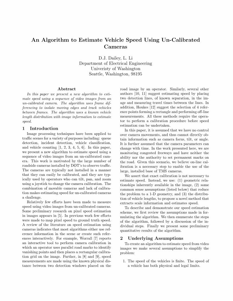
WKH DOJRULWKP� 7KH OHIW VLGH RI )LJXUH � VKRZV WZRH[DPSOH LPDJHV�
,Q VWHS �E� RI WKH DOJRULWKP� D PHGLDQ �OWHU� XVLQJD �[� NHUQHO� LV DSSOLHG WR HDFK LPDJH WR UHPRYH KLJKIUHTXHQF\ QRLVH LQ WKH LPDJHV >��� ��@�
7R LGHQWLI\ WKH PRYLQJ YHKLFOHV LQ WKH LPDJHV� WKHQRQ�PRYLQJ EDFNJURXQG PXVW EH UHPRYHG� 7ZR EDVLFWHFKQLTXHV WR UHPRYH WKH VWDWLF EDFNJURXQG LQIRUPD�WLRQ DSSHDU LQ WKH OLWHUDWXUH� 7KH �UVW LV WR REWDLQD IUDPH ZLWK RQO\ WKH EDFNJURXQG WKDW FDQ EH VXE�WUDFWHG IURP WKH IUDPHV LQ ZKLFK WKHUH DUH YHKLFOHV>��@� 7KLV IUDPH LV WKHQ XSGDWHG WR PDWFK WKH FXU�UHQW OLJKWLQJ OHYHOV >�@� 7KLV PHWKRG LV QRW RQO\ FRP�SXWDWLRQDOO\ H[SHQVLYH� EXW LW PD\ EH LPSRVVLEOH� RQFRQJHVWHG IUHHZD\V� WR REWDLQ DQ LPDJH ZLWK WKH FRU�UHFW OLJKWLQJ OHYHO DQG ZLWK QR YHKLFOHV SUHVHQW� 7KHVHFRQG WHFKQLTXH XVHV VHTXHQWLDO IUDPHV WR SHUIRUPIRUZDUG DQG EDFNZDUG GL�HUHQFHV EHWZHHQ WKH IUDPHV>��� ��� ��@� 9LHUHQ >��@ VXJJHVWV XVLQJ LQWHUIUDPH GLI�IHUHQFHV ZLWK D GL�HUHQWLDO RSHUDWRU WR H[WUDFW PRYLQJHGJHV�
7KH DOJRULWKP SUHVHQWHG KHUH XVHV LQWHUIUDPH GLI�IHUHQFHV DQG WKHQ DSSOLHV D 6REHO HGJH GHWHFWRU WR WKHUHVXOWLQJ LPDJH� 6WHS �G� RI WKH DOJRULWKP FUHDWHV WZRGL�HUHQFH LPDJHV� DQG VWHS �H� DSSOLHV WKH 6REHO HGJHGHWHFWRU WR WKRVH LPDJHV� 7KH UHVXOWLQJ LPDJHV DUHWKUHVKROGHG WR REWDLQ D ELQDU\ LPDJHV� 7KH XSSHUULJKW LPDJH LQ )LJXUH � LV WKH ELQDU\ LPDJH WKDW UH�VXOWV RI DSSO\LQJ WKH 6REHO HGJH GHWHFWRU WR WKH GLI�IHUHQFH RI WKH WZR LPDJHV LQ WKH OHIW FROXPQ RI )LJXUH�� 7KH WZR ELQDU\ LPDJHV DUH LQWHUVHFWHG LQ VWHS �I�RI WKH DOJRULWKP WR REWDLQ D PRYLQJ HGJH LPDJH� 7KHUHVXOWLQJ PRYLQJ HGJH LPDJH IRU WKH H[DPSOH VHTXHQFHDSSHDUV LQ WKH ORZHU ULJKW RI )LJXUH ��
([DPLQLQJ WKH ORZHU ULJKW LPDJH LQ )LJXUH � VKRZVWKDW ZKLOH ZH KDYH LGHQWL�HG WKH PRYLQJ HGJHV� WKRVHHGJHV GR QRW PDNH FORVHG SRO\JRQV LGHQWL�DEOH DV LQGL�YLGXDO YHKLFOHV� 7R RYHUFRPH WKLV SUREOHP DQG FUHDWHFORVHG FXUYHV� ZH XVH WZR PRUSKRORJLFDO RSHUDWLRQV�:H HQKDQFH WKH PRYLQJ HGJH LPDJH E\ VHTXHQWLDOO\DSSO\LQJ GLODWLRQ DQG HURVLRQ� >��@ 'LODWLRQ RI DQ RE�MHFW LV WKH WUDQVODWLRQ RI DOO RI LWV SRLQWV ZLWK UHJDUGWR D VWUXFWXUDO HOHPHQW IROORZHG E\ D XQLRQ RSHUDWLRQ�'LODWLRQ LV DSSOLHG WR WKH ELQDU\ LPDJH WR FORVH WKHFXUYHV LQ WKH PRYLQJ HGJH LPDJH� LW DOVR H[SDQGV WKHRYHUDOO VL]H RI WKH DUHD HQFORVHG� (URVLRQ LV WKHQ XVHGWR VKULQN WKH REMHFW EDFN WR WKH RULJLQDO VL]H� ,Q WKH DO�JRULWKP SUHVHQWHG� D �[� VWUXFWXUDO HOHPHQW LV XVHG LQVWHS �I� WR SHUIRUP GLODWLRQ DQG LQ VWHS �J� WR SHUIRUPHURVLRQ�
$IWHU WKH DSSOLFDWLRQ RI WKH PRUSKRORJLFDO RSHUD�WRUV� WKH PRYLQJ HGJHV DUH �OOHG LQ WR FUHDWH PRYLQJ
)LJXUH �� 7\SLFDO LPDJH VHTXHQFH �OHIW�� 6REHO HGJHV LQ WKH GL�HUHQFH LPDJH �ULJKWWRS�� 0RYLQJ HGJH LPDJH IRU WKH ERWWRP ULJKW LPDJH FUHDWHG E\ LQWHUVHFWLQJ GL�HU�HQFH LPDJHV� LQWHUVHFWLQJ �ULJKW ERWWRP��
EOREV� 7KHVH PRYLQJ EOREV UHSUHVHQW WKH YHKLFOH PR�WLRQ LQ WKH LPDJHV� 3DVW ZRUN KDV DVVHUWHG WKDW WKHFRQYH[ KXOO VXUURXQGLQJ D YHKLFOH LQ DQ LPDJH LV D JRRGDSSUR[LPDWLRQ RI WKH SURMHFWLRQ RI D YHKLFOH LQ WKH LP�DJH >��@� 7R FKDUDFWHUL]H WKH PRYLQJ EOREV� ZH �UVWFDOFXODWH WKH FRQYH[ KXOO IRU WKH EOREV LQ VWHS �K� RIWKH DOJRULWKP� :H DOVR FDOFXODWH WKH FHQWURLG RI WKHFRQYH[ KXOOV LQ VWHS �L�� 7KH FHQWURLGV RI WKH FRQYH[KXOOV DUH XVHG DV WKH H�HFWLYH ORFDWLRQ RI WKH YHKLFOHLQ WKH LPDJH�
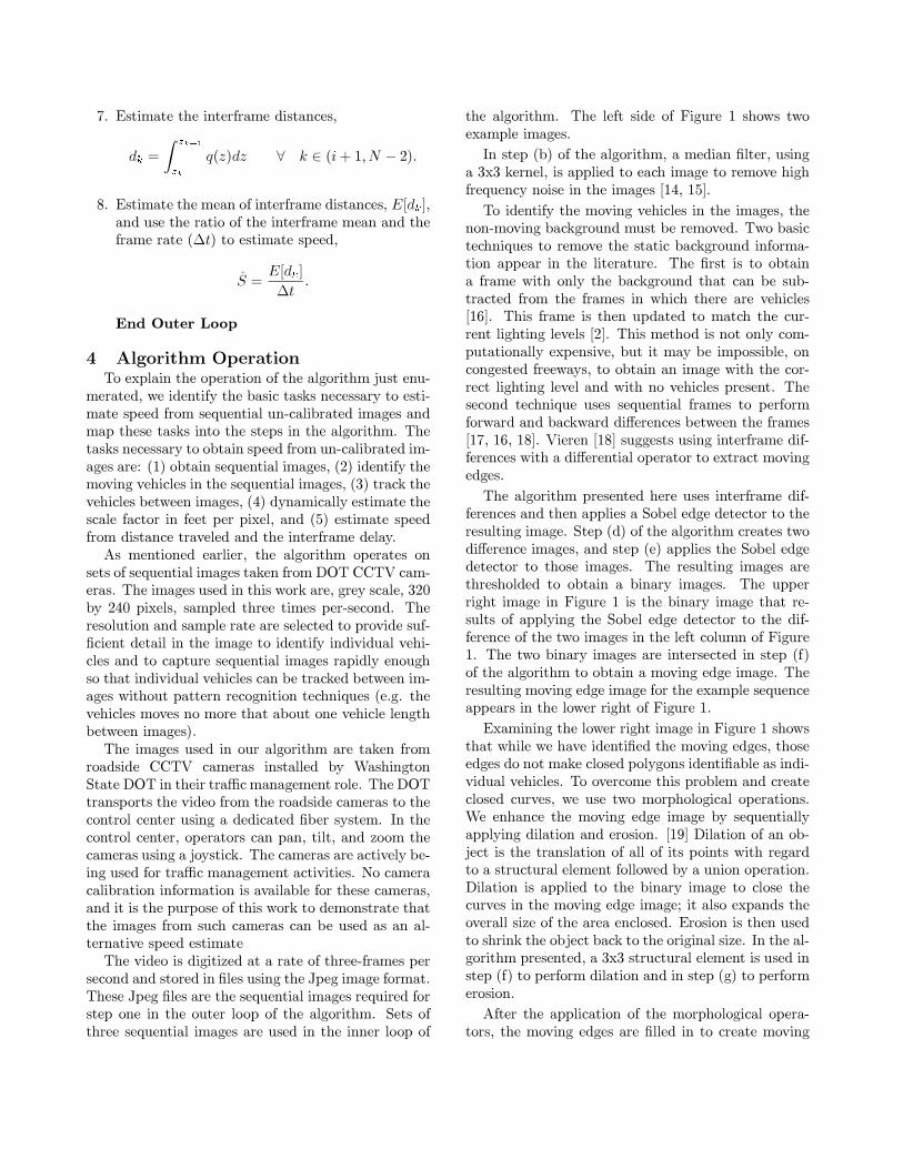
+DYLQJ ORFDWHG D YHKLFOH LQ RQH LPDJH� WKH YHKLFOHLV WUDFNHG DFURVV LPDJHV E\ HQIRUFLQJ FR�OLQHDULW\ RIWKH FHQWURLGV RI WKH FRQYH[ KXOOV� 7KH OHIW VLGH RI )LJ�XUH � SUHVHQWV D UHSUHVHQWDWLRQ RI WKUHH FRQYH[ KXOOVZLWK FHQWURLGV �[�� \��� �[�� \��� �[�� \��� ,Q VWHS ��� RIWKH DOJRULWKP� WKH YHKLFOH LV WUDFNHG DV PRYLQJ DORQJWKH OLQH DW DQ DQJOH ��� UHODWLYH WR WKH KRUL]RQWDO VFDQOLQHV LQ WKH LPDJH� ,Q WKH ZRUN SUHVHQWHG KHUH� D PLQ�LPXP YDOXH RI ���� RI WKH OLQHDU UHJUHVVLRQ FRUUHODWLRQ
FRH�FLHQW�
U
QQ;L �
[L\L �Q;
L �
[L
Q;L �
\L
�QQ;L �
[�L � �Q;L �
[L���� ��Q
Q;L �
\�L � �Q;
L �
\L���� �
�
���LV XVHG WR LGHQWLI\ FR�OLQHDU FHQWURLGV DQG WUDFN D YHKL�FOH� 7KLV FRPSOHWHV WDVNV RQH WKURXJK IRXU QHFHVVDU\WR HVWLPDWH VSHHG�7KH �IWK WDVN QHFHVVDU\ WR HVWLPDWH VSHHG LV WR
PDNH DQ HVWLPDWH RI WKH VFDOH IDFWRU WKDW PDSV GLV�WDQFH WUDYHOHG LQ WKH LPDJH WR GLVWDQFH WUDYHOHG RQ WKHURDG� :H KDYH DVVXPHG WKH YHKLFOHV DUH WDNHQ IURP DNQRZQ GLVWULEXWLRQ >��@� DQG ZH FDQ XVH WKH SURSHU�WLHV RI WKDW GLVWULEXWLRQ WR HVWLPDWH WKH OHQJWK RI WKHYHKLFOHV LQ WKH LPDJHV� :H PDNH LQGLYLGXDO HVWLPDWHVRI WKH VFDOH IDFWRU �AT� DV WKH UDWLR RI WKH PHDQ YHKLFOHOHQJWK ��O�� WDNHQ IURP WKH NQRZQ GLVWULEXWLRQ� DQG WKHHVWLPDWH RI YHKLFOH OHQJWK IURP WKH LPDJH� 7KLV ODWWHUOHQJWK LV DSSUR[LPDWHG E\ WKH OHQJWK RI WKH OLQH� LQWKH GLUHFWLRQ RI WUDYHO� FURVVLQJ WKH ERXQGLQJ ER[ VXU�URXQGLQJ WKH FRQYH[ KXOO RI WKH YHKLFOH� 7KH ULJKW VLGHRI )LJXUH � LOOXVWUDWHV WKLV DSSUR[LPDWLRQ� DQG VWHS �
a
(x3,y3)
(x2,y2)
(x1,y1)
L
L_length{a
)LJXUH �� 8VH RI FHQWURLGV WR HVWDEOLVK WKH WUDYHO GLUHFWLRQ � �OHIW�� 8VH RI ERXQGLQJER[ WR HVWLPDWH YHKLFOH OHQJWK �ULJKW��
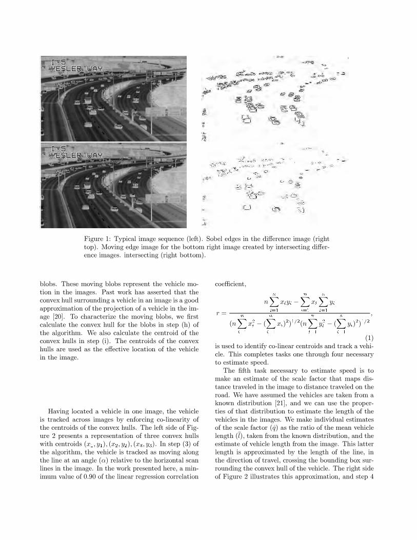
LQ WKH DOJRULWKP SURYLGHV WKLV HVWLPDWH�:H DVVXPH WKDW WKH VFDOH IDFWRU T FKDQJHV OLQHDUO\
DORQJ WKH SDWK WKDW WKH YHKLFOH WUDYHOV�
T�]MP� E� P] � E� ���
ZKHUH ] LV WKH GLVWDQFH DORQJ D OLQH DW DQ DQJOH � LQ WKHLPDJHV� 7KH SDUDPHWHUV RI WKLV VFDOH IDFWRU IXQFWLRQDUH HVWLPDWHG LQ VWHS � RI WKH DOJRULWKP XVLQJ WKH VHWRI VFDOH IDFWRU HVWLPDWHV IURP VWHS �� 7KH GLVWDQFHWUDYHOHG LV WKH LQWHJUDO RI WKLV IXQFWLRQ DORQJ WKH ]GLUHFWLRQ�
G
= ]�
]�
T�]�G]� ���
7KLV GLVWDQFH LV HVWLPDWHG LQ VWHS � RI WKH DOJRULWKP�)LQDOO\� KDYLQJ DQ HVWLPDWH RI WKH GLVWDQFH WUDYHOHG�
ZH XVH WKH LQWHUIUDPH VDPSOH WLPH LQ VWHS � WR HVWLPDWHWKH YHKLFOH VSHHG�
A6 (>GN@
�W� ���
7KLV SURYLGHV DQ HVWLPDWH RI VSHHG IURP XQ�FDOLEUDWHG FDPHUDV�
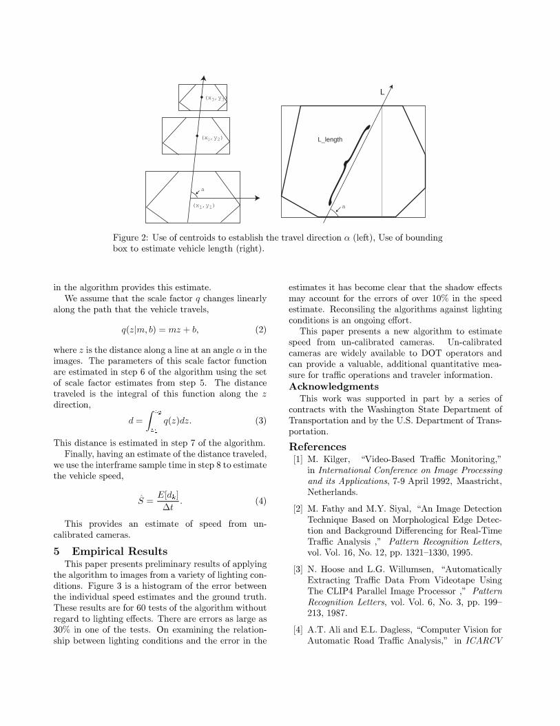
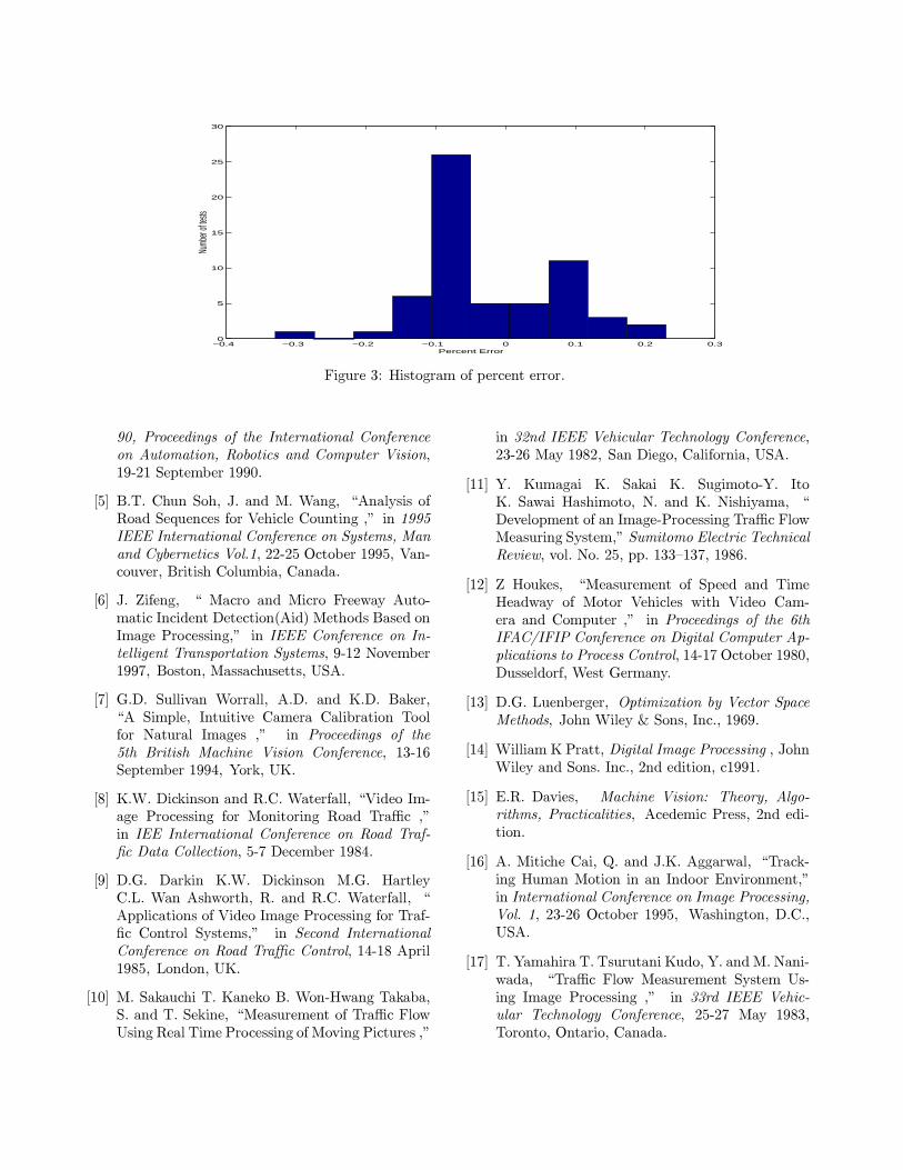
� (PSLULFDO 5HVXOWV7KLV SDSHU SUHVHQWV SUHOLPLQDU\ UHVXOWV RI DSSO\LQJ
WKH DOJRULWKP WR LPDJHV IURP D YDULHW\ RI OLJKWLQJ FRQ�GLWLRQV� )LJXUH � LV D KLVWRJUDP RI WKH HUURU EHWZHHQWKH LQGLYLGXDO VSHHG HVWLPDWHV DQG WKH JURXQG WUXWK�7KHVH UHVXOWV DUH IRU �� WHVWV RI WKH DOJRULWKP ZLWKRXWUHJDUG WR OLJKWLQJ H�HFWV� 7KHUH DUH HUURUV DV ODUJH DV��� LQ RQH RI WKH WHVWV� 2Q H[DPLQLQJ WKH UHODWLRQ�VKLS EHWZHHQ OLJKWLQJ FRQGLWLRQV DQG WKH HUURU LQ WKH
HVWLPDWHV LW KDV EHFRPH FOHDU WKDW WKH VKDGRZ H�HFWVPD\ DFFRXQW IRU WKH HUURUV RI RYHU ��� LQ WKH VSHHGHVWLPDWH� 5HFRQVLOLQJ WKH DOJRULWKPV DJDLQVW OLJKWLQJFRQGLWLRQV LV DQ RQJRLQJ H�RUW�7KLV SDSHU SUHVHQWV D QHZ DOJRULWKP WR HVWLPDWH
VSHHG IURP XQ�FDOLEUDWHG FDPHUDV� 8Q�FDOLEUDWHGFDPHUDV DUH ZLGHO\ DYDLODEOH WR '27 RSHUDWRUV DQGFDQ SURYLGH D YDOXDEOH� DGGLWLRQDO TXDQWLWDWLYH PHD�VXUH IRU WUD�F RSHUDWLRQV DQG WUDYHOHU LQIRUPDWLRQ�
$FNQRZOHGJPHQWV7KLV ZRUN ZDV VXSSRUWHG LQ SDUW E\ D VHULHV RI
FRQWUDFWV ZLWK WKH :DVKLQJWRQ 6WDWH 'HSDUWPHQW RI7UDQVSRUWDWLRQ DQG E\ WKH 8�6� 'HSDUWPHQW RI 7UDQV�SRUWDWLRQ�
5HIHUHQFHV>�@ 0� .LOJHU� ?9LGHR�%DVHG 7UD�F 0RQLWRULQJ��
LQ ,QWHUQDWLRQDO &RQIHUHQFH RQ ,PDJH 3URFHVVLQJDQG LWV $SSOLFDWLRQV� ��� $SULO ����� 0DDVWULFKW�1HWKHUODQGV�
>�@ 0� )DWK\ DQG 0�<� 6L\DO� ?$Q ,PDJH 'HWHFWLRQ7HFKQLTXH %DVHG RQ 0RUSKRORJLFDO (GJH 'HWHF�WLRQ DQG %DFNJURXQG 'L�HUHQFLQJ IRU 5HDO�7LPH7UD�F $QDO\VLV �� 3DWWHUQ 5HFRJQLWLRQ /HWWHUV�YRO� 9RO� ��� 1R� ��� SS� ����^����� �����
>�@ 1� +RRVH DQG /�*� :LOOXPVHQ� ?$XWRPDWLFDOO\([WUDFWLQJ 7UD�F 'DWD )URP 9LGHRWDSH 8VLQJ7KH &/,3� 3DUDOOHO ,PDJH 3URFHVVRU �� 3DWWHUQ5HFRJQLWLRQ /HWWHUV� YRO� 9RO� �� 1R� �� SS� ���^���� �����
>�@ $�7� $OL DQG (�/� 'DJOHVV� ?&RPSXWHU 9LVLRQ IRU$XWRPDWLF 5RDG 7UD�F $QDO\VLV�� LQ ,&$5&9
−0.4 −0.3 −0.2 −0.1 0 0.1 0.2 0.30
5
10
15
20
25
30
Percent Error
Numb
er of
tests
)LJXUH �� +LVWRJUDP RI SHUFHQW HUURU�
��� 3URFHHGLQJV RI WKH ,QWHUQDWLRQDO &RQIHUHQFHRQ $XWRPDWLRQ� 5RERWLFV DQG &RPSXWHU 9LVLRQ������ 6HSWHPEHU �����
>�@ %�7� &KXQ 6RK� -� DQG 0� :DQJ� ?$QDO\VLV RI5RDG 6HTXHQFHV IRU 9HKLFOH &RXQWLQJ �� LQ ����,((( ,QWHUQDWLRQDO &RQIHUHQFH RQ 6\VWHPV� 0DQDQG &\EHUQHWLFV 9RO��� ����� 2FWREHU ����� 9DQ�FRXYHU� %ULWLVK &ROXPELD� &DQDGD�
>�@ -� =LIHQJ� ? 0DFUR DQG 0LFUR )UHHZD\ $XWR�PDWLF ,QFLGHQW 'HWHFWLRQ�$LG� 0HWKRGV %DVHG RQ,PDJH 3URFHVVLQJ�� LQ ,((( &RQIHUHQFH RQ ,Q�WHOOLJHQW 7UDQVSRUWDWLRQ 6\VWHPV� ���� 1RYHPEHU����� %RVWRQ� 0DVVDFKXVHWWV� 86$�
>�@ *�'� 6XOOLYDQ :RUUDOO� $�'� DQG .�'� %DNHU�?$ 6LPSOH� ,QWXLWLYH &DPHUD &DOLEUDWLRQ 7RROIRU 1DWXUDO ,PDJHV �� LQ 3URFHHGLQJV RI WKH�WK %ULWLVK 0DFKLQH 9LVLRQ &RQIHUHQFH� �����6HSWHPEHU ����� <RUN� 8.�
>�@ .�:� 'LFNLQVRQ DQG 5�&� :DWHUIDOO� ?9LGHR ,P�DJH 3URFHVVLQJ IRU 0RQLWRULQJ 5RDG 7UD�F ��LQ ,(( ,QWHUQDWLRQDO &RQIHUHQFH RQ 5RDG 7UDI��F 'DWD &ROOHFWLRQ� ��� 'HFHPEHU �����
>�@ '�*� 'DUNLQ .�:� 'LFNLQVRQ 0�*� +DUWOH\&�/� :DQ $VKZRUWK� 5� DQG 5�&� :DWHUIDOO� ?$SSOLFDWLRQV RI 9LGHR ,PDJH 3URFHVVLQJ IRU 7UDI��F &RQWURO 6\VWHPV�� LQ 6HFRQG ,QWHUQDWLRQDO&RQIHUHQFH RQ 5RDG 7UD�F &RQWURO� ����� $SULO����� /RQGRQ� 8.�
>��@ 0� 6DNDXFKL 7� .DQHNR %� :RQ�+ZDQJ 7DNDED�6� DQG 7� 6HNLQH� ?0HDVXUHPHQW RI 7UD�F )ORZ8VLQJ 5HDO 7LPH 3URFHVVLQJ RI 0RYLQJ 3LFWXUHV ��
LQ ��QG ,((( 9HKLFXODU 7HFKQRORJ\ &RQIHUHQFH������ 0D\ ����� 6DQ 'LHJR� &DOLIRUQLD� 86$�
>��@ <� .XPDJDL .� 6DNDL .� 6XJLPRWR�<� ,WR.� 6DZDL +DVKLPRWR� 1� DQG .� 1LVKL\DPD� ?'HYHORSPHQW RI DQ ,PDJH�3URFHVVLQJ 7UD�F )ORZ0HDVXULQJ 6\VWHP�� 6XPLWRPR (OHFWULF 7HFKQLFDO5HYLHZ� YRO� 1R� ��� SS� ���^���� �����
>��@ = +RXNHV� ?0HDVXUHPHQW RI 6SHHG DQG 7LPH+HDGZD\ RI 0RWRU 9HKLFOHV ZLWK 9LGHR &DP�HUD DQG &RPSXWHU �� LQ 3URFHHGLQJV RI WKH �WK,)$&�,),3 &RQIHUHQFH RQ 'LJLWDO &RPSXWHU $S�SOLFDWLRQV WR 3URFHVV &RQWURO� ����� 2FWREHU �����'XVVHOGRUI� :HVW *HUPDQ\�
>��@ '�*� /XHQEHUJHU� 2SWLPL]DWLRQ E\ 9HFWRU 6SDFH0HWKRGV� -RKQ :LOH\ 6RQV� ,QF�� �����
>��@ :LOOLDP . 3UDWW� 'LJLWDO ,PDJH 3URFHVVLQJ � -RKQ:LOH\ DQG 6RQV� ,QF�� �QG HGLWLRQ� F�����
>��@ (�5� 'DYLHV� 0DFKLQH 9LVLRQ� 7KHRU\� $OJR�ULWKPV� 3UDFWLFDOLWLHV� $FHGHPLF 3UHVV� �QG HGL�WLRQ�
>��@ $� 0LWLFKH &DL� 4� DQG -�.� $JJDUZDO� ?7UDFN�LQJ +XPDQ 0RWLRQ LQ DQ ,QGRRU (QYLURQPHQW��LQ ,QWHUQDWLRQDO &RQIHUHQFH RQ ,PDJH 3URFHVVLQJ�9RO� �� ����� 2FWREHU ����� :DVKLQJWRQ� '�&��86$�
>��@ 7� <DPDKLUD 7� 7VXUXWDQL .XGR� <� DQG 0� 1DQL�ZDGD� ?7UD�F )ORZ 0HDVXUHPHQW 6\VWHP 8V�LQJ ,PDJH 3URFHVVLQJ �� LQ ��UG ,((( 9HKLF�XODU 7HFKQRORJ\ &RQIHUHQFH� ����� 0D\ �����7RURQWR� 2QWDULR� &DQDGD�
>��@ )� &DEHVWDLQJ 9LHUHQ� &� DQG -�*� 3RVWDLUH� ?&DWFKLQJ 0RYLQJ 2EMHFWV ZLWK 6QDNHV IRU 0RWLRQ7UDFNLQJ�� 3DWWHUQ 5HFRJQLWLRQ /HWWHUV� YRO� 9RO���� 1R� �� SS� ���^���� �����
>��@ -HDQ 3DXO 6HUUD� ,PDJH $QDO\VLV DQG 0DWKHPDW�LFDO 0RUSKRORJ\ � $FDGHPLF 3UHVV� �����
>��@ 5� 0LODQHVH *LO� 6� DQG 7� 3XQ� ?&RPSDULQJ)HDWXUHV IRU 7DUJHW 7UDFNLQJ LQ 7UD�F 6FHQHV ��3DWWHUQ 5HFRJQLWLRQ� YRO� 9RO� ��� 1R� �� SS� ����^����� �����
>��@ '�-� 'DLOH\� ?$ 6WDWLVWLFDO $OJRULWKP IRU (V�WLPDWLQJ 6SHHG IURP 6LQJOH /RRS 9ROXPH DQG2FFXSDQF\ 0HDVXUHPHQWV �� 7UDQV 5HVHDUFK %������