victoreen 451p & 451p-de-si - fluke corporation: fluke
TRANSCRIPT

Victoreen® 451P & 451P-DE-SI
Ion Chamber Survey Meter
Operators Manual
February 2005
Manual No. 1020101000 Rev. 2 ©2004, 2005 Fluke Corporation, All rights reserved. Printed in U.S.A. All product names are trademarks of their respective companies

Fluke Biomedical Radiation Management Services 6045 Cochran Road Cleveland, Ohio 44139 440.498.2564 www.flukebiomedical.com/rms
i
Table Of Contents
Section 1: General Information ...................................................................... 1-1 1.1 Introduction .................................................................................................. 1-1 1.2 Features....................................................................................................... 1-1 1.3 Receiving Inspection.................................................................................... 1-2 1.4 Specifications............................................................................................... 1-2
Section 2: Operation ..................................................................................... 2-1 2.1 External Controls ......................................................................................... 2-1 2.2 Installation.................................................................................................... 2-2
Section 3: Theory Of Operation...................................................................... 3-1 3.1 Introduction .................................................................................................. 3-1 3.2 Firmware...................................................................................................... 3-2
Section 4: Maintenance ................................................................................. 4-1 4.1 Introduction .................................................................................................. 4-1 4.2 Routine Cleaning ......................................................................................... 4-1 4.3 Storage ........................................................................................................ 4-1 4.4 Battery Replacement ................................................................................... 4-2 4.5 High Voltage Battery Board Replacement ................................................... 4-3 4.6 Replacement Parts Information ................................................................... 4-3 4.7 Recalibration and Service Information ......................................................... 4-4

General InformationIntroduction 1
1-1
Section 1 GENERAL INFORMATION
1.1 Introduction
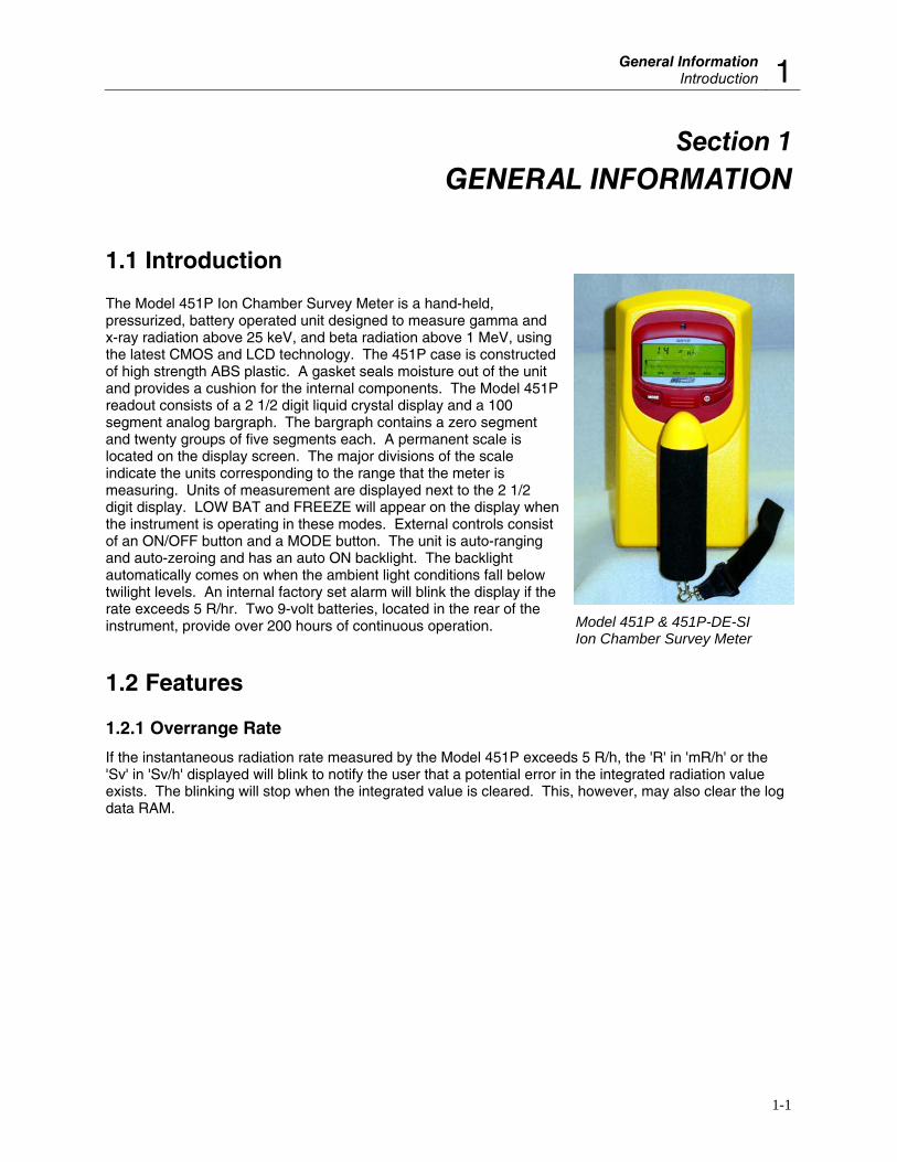
The Model 451P Ion Chamber Survey Meter is a hand-held, pressurized, battery operated unit designed to measure gamma and x-ray radiation above 25 keV, and beta radiation above 1 MeV, using the latest CMOS and LCD technology. The 451P case is constructed of high strength ABS plastic. A gasket seals moisture out of the unit and provides a cushion for the internal components. The Model 451P readout consists of a 2 1/2 digit liquid crystal display and a 100 segment analog bargraph. The bargraph contains a zero segment and twenty groups of five segments each. A permanent scale is located on the display screen. The major divisions of the scale indicate the units corresponding to the range that the meter is measuring. Units of measurement are displayed next to the 2 1/2 digit display. LOW BAT and FREEZE will appear on the display when the instrument is operating in these modes. External controls consist of an ON/OFF button and a MODE button. The unit is auto-ranging and auto-zeroing and has an auto ON backlight. The backlight automatically comes on when the ambient light conditions fall below twilight levels. An internal factory set alarm will blink the display if the rate exceeds 5 R/hr. Two 9-volt batteries, located in the rear of the instrument, provide over 200 hours of continuous operation.
1.2 Features
1.2.1 Overrange Rate
If the instantaneous radiation rate measured by the Model 451P exceeds 5 R/h, the 'R' in 'mR/h' or the 'Sv' in 'Sv/h' displayed will blink to notify the user that a potential error in the integrated radiation value exists. The blinking will stop when the integrated value is cleared. This, however, may also clear the log data RAM.
Model 451P & 451P-DE-SI Ion Chamber Survey Meter
Victoreen 451P & 451P-DE-SI Operators Manual
1-2
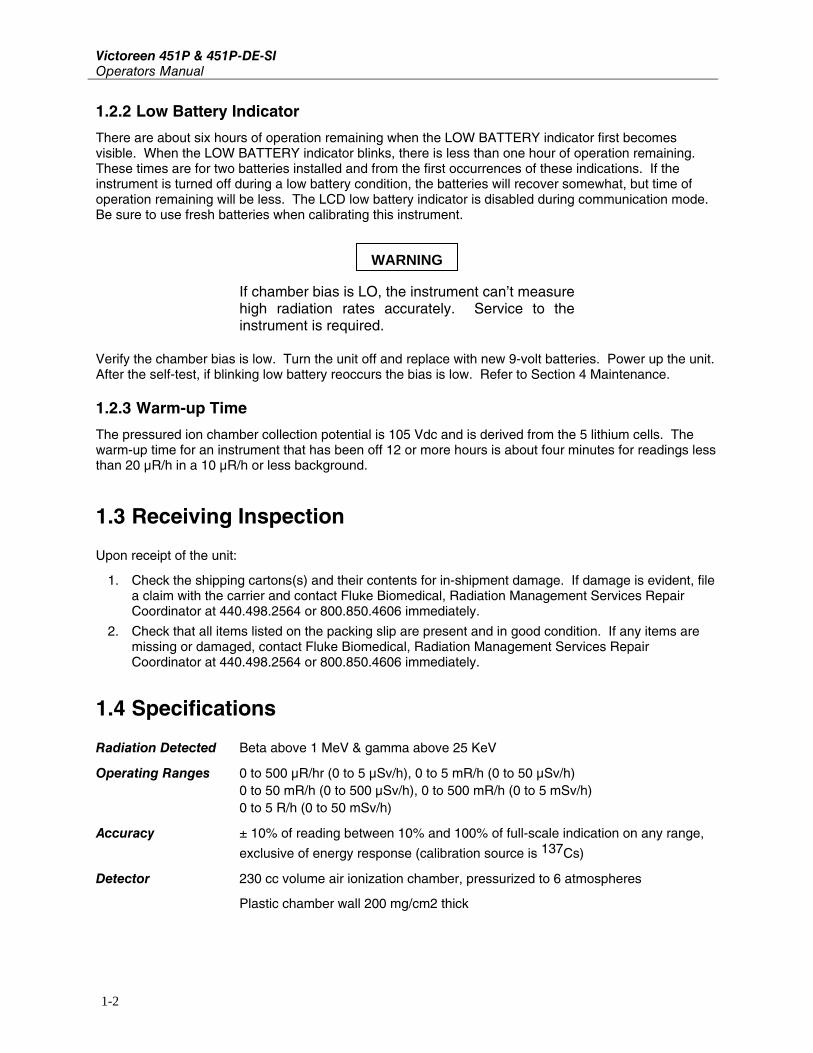
1.2.2 Low Battery Indicator
There are about six hours of operation remaining when the LOW BATTERY indicator first becomes visible. When the LOW BATTERY indicator blinks, there is less than one hour of operation remaining. These times are for two batteries installed and from the first occurrences of these indications. If the instrument is turned off during a low battery condition, the batteries will recover somewhat, but time of operation remaining will be less. The LCD low battery indicator is disabled during communication mode. Be sure to use fresh batteries when calibrating this instrument.
If chamber bias is LO, the instrument can’t measure high radiation rates accurately. Service to the instrument is required.
Verify the chamber bias is low. Turn the unit off and replace with new 9-volt batteries. Power up the unit. After the self-test, if blinking low battery reoccurs the bias is low. Refer to Section 4 Maintenance.
1.2.3 Warm-up Time
The pressured ion chamber collection potential is 105 Vdc and is derived from the 5 lithium cells. The warm-up time for an instrument that has been off 12 or more hours is about four minutes for readings less than 20 μR/h in a 10 μR/h or less background.
1.3 Receiving Inspection
Upon receipt of the unit:
1. Check the shipping cartons(s) and their contents for in-shipment damage. If damage is evident, file a claim with the carrier and contact Fluke Biomedical, Radiation Management Services Repair Coordinator at 440.498.2564 or 800.850.4606 immediately.
2. Check that all items listed on the packing slip are present and in good condition. If any items are missing or damaged, contact Fluke Biomedical, Radiation Management Services Repair Coordinator at 440.498.2564 or 800.850.4606 immediately.
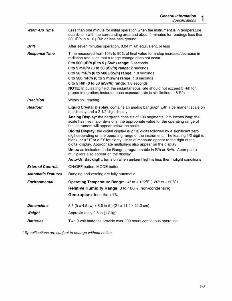
1.4 Specifications
Radiation Detected Beta above 1 MeV & gamma above 25 KeV
Operating Ranges 0 to 500 μR/hr (0 to 5 μSv/h), 0 to 5 mR/h (0 to 50 μSv/h) 0 to 50 mR/h (0 to 500 μSv/h), 0 to 500 mR/h (0 to 5 mSv/h) 0 to 5 R/h (0 to 50 mSv/h)
Accuracy ± 10% of reading between 10% and 100% of full-scale indication on any range,
exclusive of energy response (calibration source is 137Cs)
Detector 230 cc volume air ionization chamber, pressurized to 6 atmospheres
Plastic chamber wall 200 mg/cm2 thick
WARNING
General InformationSpecifications 1
1-3
Warm-Up Time Less than one minute for initial operation when the instrument is in temperature equilibrium with the surrounding area and about 4 minutes for readings less than 20 μR/h in a 10 μR/h or less background
Drift After seven minutes operation, 0.04 mR/h equivalent, or less
Response Time Time measured from 10% to 90% of final value for a step increase/decrease in radiation rate such that a range change does not occur:
0 to 500 μR/h (0 to 5 μSv/h) range: 5 seconds 0 to 5 mR/hr (0 to 50 μSv/h) range: 2 seconds 0 to 50 mR/h (0 to 500 μSv/h) range: 1.8 seconds 0 to 500 mR/h (0 to 5 mSv/h) range: 1.8 seconds 0 to 5 R/h (0 to 50 mSv/h) range: 1.8 seconds NOTE: In pulsating field, the instantaneous rate should not exceed 5 R/h for
proper integration; instantaneous exposure rate is still limited to 5 R/h
Precision Within 5% reading
Readout Liquid Crystal Display: contains an analog bar graph with a permanent scale on the display and a 2 1/2 digit display
Analog Display: the bargraph consists of 100 segments, 2 ½ inches long; the scale has five major divisions; the appropriate value for the operating range of the instrument will appear below the scale
Digital Display: the digital display is 2 1/2 digits followed by a significant zero digit depending on the operating range of the instrument. The leading 1/2 digit is blank, or a “1” or a “0” for clarity. Units of measure appear to the right of the digital display. Appropriate multipliers also appear on the display
Units: as indicated under Range, programmable in R/h or Sv/h. Appropriate multipliers also appear on the display
Auto-On Backlight: turns on when ambient light is less then twilight conditions
External Controls ON/OFF button, MODE button
Automatic Features Ranging and zeroing are fully automatic.
Environmental Operating Temperature Range: - 4º to + 122ºF (- 20º to + 50ºC)
Relative Humidity Range: 0 to 100%, non-condensing
Geotropism: less than 1% Dimensions 8.5 (l) x 4.5 (w) x 8.6 in (h) (21 x 11.4 x 21.3 cm)
Weight Approximately 2.6 lb (1.2 kg)
Batteries Two 9-volt batteries provide over 200 hours continuous operation
* Specifications are subject to change without notice.
Victoreen 451P & 451P-DE-SI Operators Manual
1-4
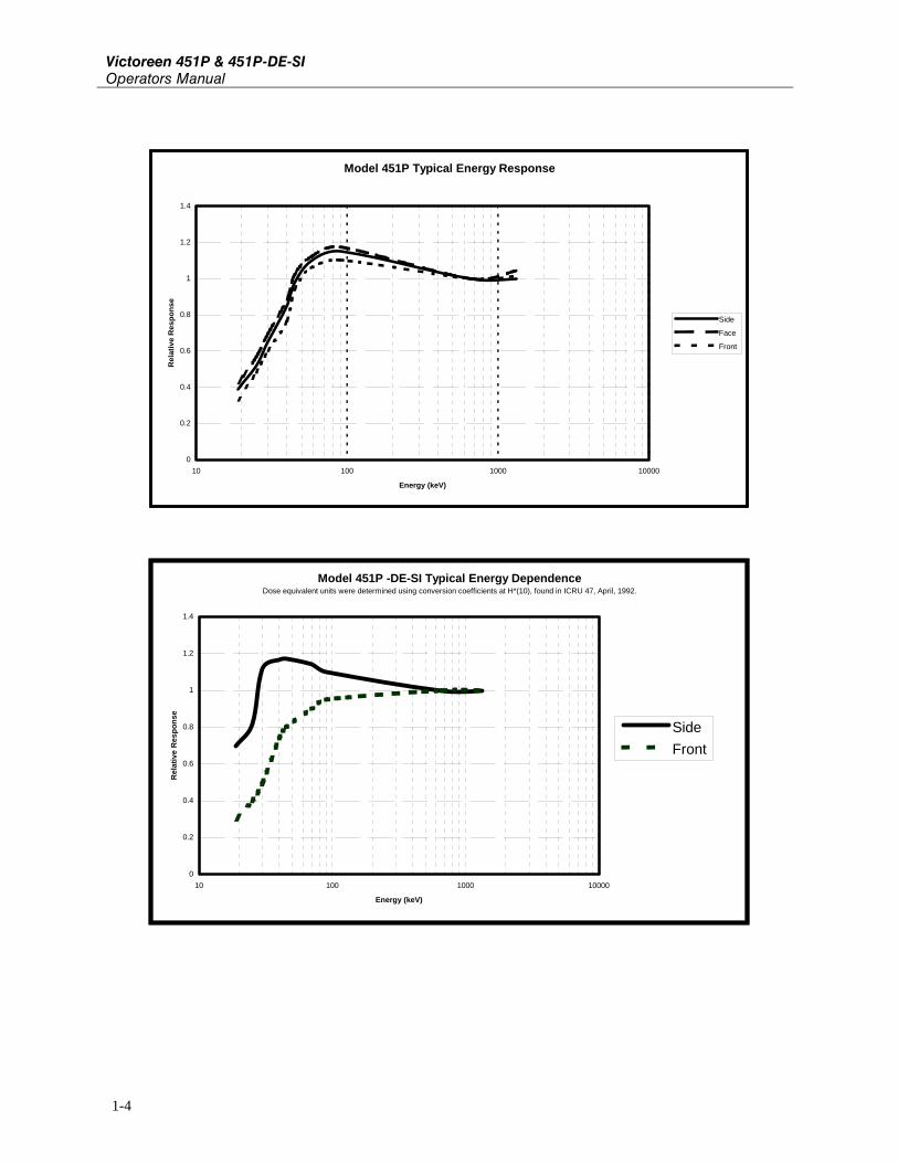
Model 451P Typical Energy Response
0
0.2
0.4
0.6
0.8
1
1.2
1.4
10 100 1000 10000
Energy (keV)
Rel
ativ
e R
espo
nse
Side
Face
Front
Model 451P -DE-SI Typical Energy DependenceDose equivalent units were determined using conversion coefficients at H*(10), found in ICRU 47, April, 1992.
0
0.2
0.4
0.6
0.8
1
1.2
1.4
10 100 1000 10000
Energy (keV)
Rel
ativ
e R
espo
nse
SideFront
General InformationSpecifications 1
1-5
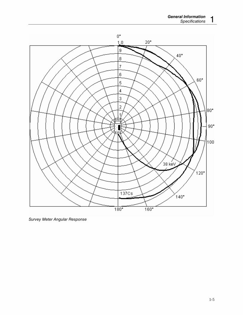
Survey Meter Angular Response

Victoreen 451P & 451P-DE-SI Operators Manual
OperationExternal Controls 2
2-1
Section 2 Operation
2.1 External Controls
There are two external controls on the survey meter: an ON/OFF button and a MODE button.
2.1.1 ON/OFF Button
Press the ON/OFF button to turn the unit on. All the elements in the display turn on and the microprocessor runs through an initialization procedure. Part of the procedure includes reading the calibration coefficients stored in EEPROM. If an EEPROM read error occurs, an error code (E1) will be displayed at power-on and unity calibration coefficients will be used.
The bargraph and digital display will show a reading that decreases as the instrument stabilizes. The initial reading usually starts in the 5 R/h range and decreases through the lower ranges to a reading of less than 50 μR/h within 120 seconds. When the element---s in the display turn off, with the exception of those necessary for normal operation, the user can begin the measurement process.
A one-minute warm-up period is recommended before making a measurement. If the unit experiences an extreme temperature change (e.g., moving inside from outside), a longer warm-up period may be required to obtain a value less than 50 μR/h.
2.1.2 MODE Button
To configure the MODE button to the opposite function without a RS-232 connection, use the following procedure:
1. Turn the unit off.
2. Press the MODE button.
3. Turn the unit on while continuing to press the MODE button.
4. Release the MODE button when the display is in the “all elements on” condition.
5. Use the MODE button to toggle the instrument between the Rate mode and the newly selected Freeze or Integrate mode.
NOTE
Victoreen 451P & 451P-DE-SI Operators Manual
2-2
2.1.3 Freeze Mode
When configured to select the Freeze mode, the MODE button acts as a toggle switch. Press the button until FREEZE appears on the display. Operation in the Freeze mode gives the user a constant reference of the highest exposure rate obtained from the time the freeze function is initialized. The highest reading will appear as a single bar on the bargraph. The current reading will continue to be displayed on the digital display and the bargraph. If a measurement is obtained which exceeds the freeze bar reading, the freeze bar will move to the higher measurement point. The operating range of the 451P remains locked on the highest range attained during the Freeze mode so that the scale and the multiplier remain the same.
For example, assume the scale units appear as 10, 20, 30, 40, 50, and the freeze bar is at 47 mR/h on the bargraph. If the 451P then measures a radiation field of 120 mR/h, the scale units will change to 100, 200, 300, 400, 500 and the freeze bar will appear on the graph at 120 mR/h. If the survey meter measurement goes below 100 mR/h, the units on the scale will not change until the survey meter is taken out of the freeze mode. However, the digital display will continue to show the current reading. The survey meter will operate in the Freeze mode until the user toggles the MODE button to return to the normal operating mode.
2.1.4 Integrate Mode
The Integrate mode is operational 30 seconds after the instrument is turned on and all of the time after that. However, the integrated exposure can only be displayed when the MODE button has been configured as a toggle to display exposure rate/integrated exposure. If the MODE button is pressed within the 30-second initialization period of the unit, the display will read “0”. When integration starts, “0.0 μR” will be displayed. Toggle MODE to read exposure rate as required. To reset the integration display, toggle the display from the Rate mode to the Integrate mode. Keep the MODE button pressed for about 5 seconds. The display will clear, and then read “0.0 μR.” Exposures are accumulated up to 99 R.
2.1.5 Self Test
When the 451P survey meter is first turned on, it runs through a functional self test procedure. During this self-test, the firmware version of the unit is displayed. If the unit passes the self-test, it will go into the normal operating mode. If the unit fails the self-test, it will remain locked with the firmware revision displayed. Consult a Fluke Biomedical, Radiation Management Services Repair Coordinator for corrective action.
2.2 Installation
The Model 451P periodically tests for input at its RS-232 port. The model 451P sends test signals, if the RS-232 is present and operational, the survey meter will enter into the communications mode. The 451P display will clear and the letters “CO” will be displayed as an indication that the unit is in the communications mode.
The RS-232 port is compatible with a CRT or printing terminal having a standard RS-232 connector and a 1200-baud rate. A computer with a modem or terminal emulator may be used in place of the terminal. The terminal or computer should be set up for a 1200 baud, 7 data bits, no parity bit, and 1 stop bits (i.e., 7 data bits, no parity, and 1 stop bit). To establish communications, perform the following:
1. Attach the RS-232 cable assembly to the back of the survey meter.
2. When “CO” appears on the 451P display, press the computer or terminal spacebar.
OperationInstallation 2
2-3
If the Model 451 displays the “CO” message, but there is no response at the terminal press the spacebar twice.
If there is a problem getting the communications message (CO) to be displayed on the 451P:
1. Be sure the computer communication port is active.
2. The 451 communication transmitter/RCR pair is active when it detects a negative mark voltage at the receiver input. (CO) shall appear on the 451 display.
3. Press space bar twice.
If there is still a problem, consult the Fluke Biomedical, Radiation Management Services Repair Coordinator for further instructions.

Victoreen 451P & 451P-DE-SI Operators Manual
Theory Of OperationIntroduction 3
3-1
Section 3 Theory Of Operation
3.1 Introduction
The user is cautioned about indiscriminately opening and disassembling the instrument. The ionization chamber is pressurized and sealed at the factory, because the high impedance circuits of the ion chamber are easily contaminated with grease and dirt that produce electrical leakage. The ion chamber cannot be disassembled for servicing
The Model 451P is a pressurized ionization chamber instrument calibrated in exposure rate units of roentgens/hour (or sieverts/hour) for gamma and x-radiation in the energy range of 20 keV to 2 MeV. The Model 451P responds to, but is not calibrated for beta radiation. Beta energies that can be measured are above 1 MeV.
The liquid crystal, supertwist display shows the radiation rate in digital and analog form with the range multiplier values also showing on the scale. It is a lightweight electronic device that requires the computational capabilities of a microprocessor to make it operate. It functions in a multiplex mode called quadriplex. This mode uses four (4) back-planes to accommodate the 128 elements of the display.
The microprocessor performs data collection, averaging, and multiplication by stored calibration factors, range changing, and battery check functions, in addition to driving the LCD. Between computational periods, it “sleeps” in a low power mode to conserve battery power. The microprocessor reads stored information from an electrically erasable memory, EEPROM, which is used by the program for calibration and display units. The EEPROM will retain stored data when the instrument is OFF or when the batteries are removed. Data can be entered into the EEPROM using the RS-232 port.
Collection voltage for the ion chamber is approximately 105 V obtained from 5 lithium cells. All internal power for the instrument is supplied by the 9-volt batteries.
The digital and bargraph displays read directly. The bargraph display update periods are listed in the table below. The digital display updates at one second intervals nearest the current bar display update. The bargraph and digits display do not always show the same reading because the bargraph is faster than the digital update. It is more convenient to watch the bargraph when the reading is changing quickly and to read the value of a slowly changing or static reading by looking at the digital display.
The bargraph display is a digital presentation, programmed to appear as a linear analog meter display. It is also referred to as the analog display throughout this manual.
NOTE
Victoreen 451P & 451P-DE-SI Operators Manual
3-2
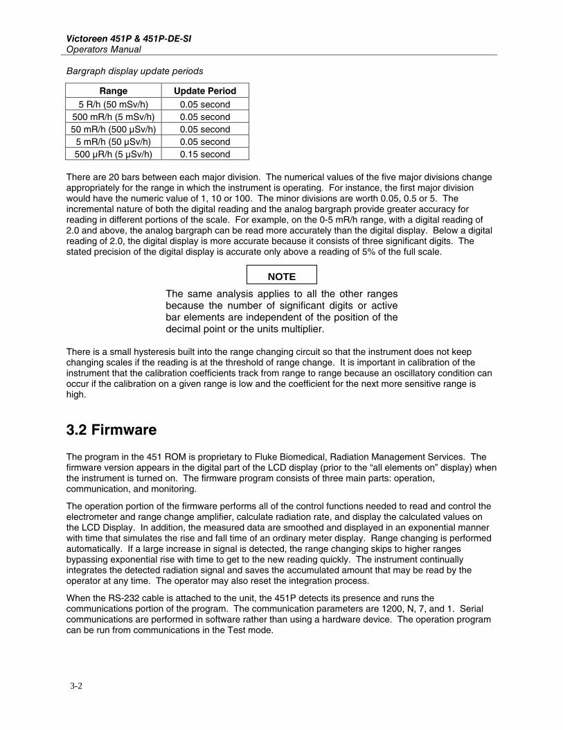
Bargraph display update periods
Range Update Period 5 R/h (50 mSv/h) 0.05 second
500 mR/h (5 mSv/h) 0.05 second 50 mR/h (500 μSv/h) 0.05 second
5 mR/h (50 μSv/h) 0.05 second 500 μR/h (5 μSv/h) 0.15 second
There are 20 bars between each major division. The numerical values of the five major divisions change appropriately for the range in which the instrument is operating. For instance, the first major division would have the numeric value of 1, 10 or 100. The minor divisions are worth 0.05, 0.5 or 5. The incremental nature of both the digital reading and the analog bargraph provide greater accuracy for reading in different portions of the scale. For example, on the 0-5 mR/h range, with a digital reading of 2.0 and above, the analog bargraph can be read more accurately than the digital display. Below a digital reading of 2.0, the digital display is more accurate because it consists of three significant digits. The stated precision of the digital display is accurate only above a reading of 5% of the full scale.
The same analysis applies to all the other ranges because the number of significant digits or active bar elements are independent of the position of the decimal point or the units multiplier.
There is a small hysteresis built into the range changing circuit so that the instrument does not keep changing scales if the reading is at the threshold of range change. It is important in calibration of the instrument that the calibration coefficients track from range to range because an oscillatory condition can occur if the calibration on a given range is low and the coefficient for the next more sensitive range is high.
3.2 Firmware
The program in the 451 ROM is proprietary to Fluke Biomedical, Radiation Management Services. The firmware version appears in the digital part of the LCD display (prior to the “all elements on” display) when the instrument is turned on. The firmware program consists of three main parts: operation, communication, and monitoring.
The operation portion of the firmware performs all of the control functions needed to read and control the electrometer and range change amplifier, calculate radiation rate, and display the calculated values on the LCD Display. In addition, the measured data are smoothed and displayed in an exponential manner with time that simulates the rise and fall time of an ordinary meter display. Range changing is performed automatically. If a large increase in signal is detected, the range changing skips to higher ranges bypassing exponential rise with time to get to the new reading quickly. The instrument continually integrates the detected radiation signal and saves the accumulated amount that may be read by the operator at any time. The operator may also reset the integration process.
When the RS-232 cable is attached to the unit, the 451P detects its presence and runs the communications portion of the program. The communication parameters are 1200, N, 7, and 1. Serial communications are performed in software rather than using a hardware device. The operation program can be run from communications in the Test mode.
NOTE

MaintenanceIntroduction 4
4-1
Section 4 Maintenance
4.1 Introduction
Very little maintenance is required for the survey meter, but some periodic attention may be necessary, especially if the instrument is used in harsh industrial conditions.
4.2 Routine Cleaning
Do not immerse the Model 451P or 451P-DE-SI. The unit is not waterproof, liquid could damage the circuits. The unit should be kept clean and free from dirt and contamination. The unit may be cleaned by wiping with a damp cloth using any commercially available cleaning or decontaminating agent.
4.3 Storage
Storage of Fluke Biomedical, Radiation Management Services instruments must comply with Level B storage requirements as outlined in ANSI N45.2.2 (1972), Section 6.1.2 (.2). The storage area shall comply with ANSI N45.2.2 (1972), Section 6.2 Storage Area, paragraphs 6.2.1 through 6.2.5. Housekeeping shall conform to ANSI N45.2.3 (1972).
Level B components must be stored within a fire resistant, tear resistant, weather tight enclosure, in a well-ventilated building or equivalent.
Storage of Fluke Biomedical, Radiation Management Services instruments must comply with the following considerations:
1. Inspection and examination of items in storage must be in accordance with ANSI N45.2.2 (1972), Section 6.4.1.
2. Requirements for proper storage must be documented and written procedures, or instructions shall be established.
3. In the event of a fire, post-fire evaluation must be in accordance with ANSI N45.2.2 (1972), Section 6.4.3.
4. Removal of items from storage must be in accordance with ANSI N45.2.2 (1972), Sections 6.5 and 6.6.

Victoreen 451P & 451P-DE-SI Operators Manual
4-2
4.4 Battery Replacement
The LOW BAT message will appear on the display approximately six hours prior to the instrument becoming inoperable. To ensure that the instrument operates to specification, it is recommended that the batteries be changed within 4 hours after the LO BAT message appears. The instrument will function on one battery for approximately 100 hours, allowing replacement of one battery at a time if the instrument must remain operational during battery changeover. Regular or alkaline batteries can be used for replacement purposes.
Both 9-volt batteries are located in the rear of the unit and are easily accessible and replaceable with the battery cover removed.
Be sure to observe proper polarity when replacing the batteries.
Battery Access
INOVISION
S/N
Model
NOTE

MaintenanceHigh Voltage Battery Board Replacement 4
4-3
4.5 High Voltage Battery Board Replacement
This assembly contains the lithium cells for chamber bias.
1. Remove the 9-volt batteries to be sure that the instrument will remain off during the disassembly process.
2. Remove the four screws from the case top.
3. Carefully remove the case bottom from the thick gasket that seals the top and bottom.
4. Remove the two screws, lock washers and metal spacers, holding the battery board in place.
5. To replace the five 21 V lithium cells, remove the old lithium cells by unsoldering, and solder into place the new lithium cells. Battery boards and cells are listed in the Replaceable Parts Information section.
Surface below High Voltage Board is conductive!
6. Secure the battery board to the survey meter assembly with the two screws, lock washers and aluminum spacers removed in step 4.
7. Secure the case top to the case bottom, with the gasket in between, using the four screws removed in step 2.
8. Replace the 9-volt batteries, being sure to observe proper polarity.
4.6 Replaceable Parts Information
Fluke Biomedical, Radiation Management Services maintains a complete inventory of all normal replaceable parts. To place an order, or to obtain information concerning replaceable parts, contact the Fluke Biomedical, Radiation Management Services Repair Coordinator at 800.850.4606, 440.498.2564, or Fax: 440.542.3682.
Replaceable parts list
Part Number Description:
1020023002 Keypad Overlay, Yellow
1020023001 Keypad Overlay, Red
1020024003 Handle, Gray
1020024002 Handle, Yellow
450P-1-20 High Voltage Battery Board Assembly
181061 Lithium Battery Assembly, 7-CR 1220 Lithium Cells
1020026000 Handle, Foam Grip
WARNING

Victoreen 451P & 451P-DE-SI Operators Manual
4-4
4.7 Recalibration And Service Information
If your instrument needs recalibration or repair, we request that you consult the Fluke Biomedical, Radiation Management Services Repair Coordinator at 800.850.4606, 440.498.2564, or Fax: 440.542.3682.
More information concerning the operation, application, or service of your instrument may be obtained from the applications engineer at the numbers listed above.


Fluke Biomedical Radiation Management Services 6045 Cochran Road Cleveland, Ohio 44139 440.498.2564 www.flukebiomedical.com/rms