vibrosight ® software version 2.11 - meggitt sensing
TRANSCRIPT

Release Notes VIBROSIGHT-RN/E (660-010-013-203A)
Release 2.11.0 – November 2013 www.meggittsensingsystems.com
www.vibro-meter.com
RELEASE NOTES
VibroSight ® software version 2.11.0
Meggitt SA Route de Moncor 4
PO Box 1616
CH - 1701 Fribourg
SWITZERLAND
2 / 43 Release Notes VIBROSIGHT-RN/E (660-010-013-203A)
Release 2.11.0 – November 2013
REVISION RECORD SHEET
SW version / RN edition
Date of issue Written and modified by
Description Signature
2.11.0 / 1 26 November 2013 P. Ward This document corresponds to VibroSight version 2.11.0.
PW
Department Name Date Signature
Technical content approved by
Engineering J. Theraulaz 26 November 2013 JT
Product Management A. Fernandez 26 November 2013 AF
Document released by
Technical Publications P. Ward 26 November 2013 PW
The duly signed master copy of this page is stored by the Technical Publications Department of
Meggitt SA and can be obtained by writing to the Technical Publications Manager.

Release Notes VIBROSIGHT-RN/E (660-010-013-203A)
Release 2.11.0 – November 2013 3 / 43
IMPORTANT NOTICE
All statements, technical information and recommendations in this document which relate to the
products supplied by Meggitt Sensing Systems are based on information believed to be reliable, but
unless otherwise expressly agreed in writing with Meggitt SA, the accuracy or completeness of such
data is not guaranteed. Before using this product, you must evaluate it and determine if it is suitable
for your intended application. Unless otherwise expressly agreed in writing with Meggitt SA, you
assume all risks and liability associated with such use. Meggitt Sensing Systems takes no
responsibility for any statements related to the product which are not contained in a current English
language Meggitt Sensing Systems publication, nor for any statements contained in extracts,
summaries, translations or any other documents not authored and produced by Meggitt Sensing
Systems.
EXPORT CONTROL
The information contained in this document may be subject to export control regulations of the
European Community, USA or other countries. Each recipient of this document is responsible for
ensuring that the transfer or use of any information contained in this document complies with all
relevant export control regulations. ECN N /A.
COPYRIGHT
Copyright © Meggitt SA, 2013
All rights reserved
Published and printed by Meggitt SA in Fribourg, Switzerland
The names of actual companies and products mentioned
herein may be the trademarks of their respective owners.
The information contained in this document is subject to change without notice.
This information shall not be used, duplicated or disclosed, in whole or in part,
without the express written permission of Meggitt Sensing Systems.

4 / 43 Release Notes VIBROSIGHT-RN/E (660-010-013-203A)
Release 2.11.0 – November 2013
PREFACE
About these release notes
This document provides important information about the VibroSight ® software from Meggitt Sensing
Systems. It is applicable to all VibroSight-based condition monitoring and machinery protection
systems using the versions of software described by this document, namely:
VibroSight software version 2.11.0 (CD part number 609-004-000-020).
This document contains information about changes to the software since the previously released
version (VibroSight 2.10.1), such as new features and improvements, solved problems and bug fixes,
and hardware and software compatibility.
For more general information on the actual software, or the entire condition monitoring system (CMS),
refer to the following Meggitt Sensing Systems (MSS) documentation:
VibroSight software data sheet
(MSS document ref. 660-020-005-213A)
Getting started with VibroSight installation guide
(MSS document ref. 660-010-006-216A)
VibroSight help
XMV16 / XIO16T extended vibration monitoring card pair data sheet
(MSS document ref. 660-020-010-206A)
VibroSight application notes and technical notes.
Users who are familiar with previous versions of VibroSight may also find it useful to refer to the
respective release notes included in their installation.
Structure of the release notes
This document presents information in the following order: general items first, then in terms of the
software modules that constitute VibroSight, such as Configurator, Server, Vision and so
on.
You should read those sections that are most relevant to you and then keep the document for future
reference.

Release Notes VIBROSIGHT-RN/E (660-010-013-203A)
Release 2.11.0 – November 2013 5 / 43
Version identifiers
A complete VibroSight software product version number has four components x.x.x build x (or x.x.x.x)
that provide the following information:
Major release identifier: x.x.x build x (or x.x.x.x)
Minor release identifier: x.x.x build x (or x.x.x.x)
Update identifier: x.x.x build x (or x.x.x.x)
Build identifier: x.x.x build x (or x.x.x.x)
The version identifiers for installed software appear in the Help About box (obtained using
Help > About … in any VibroSight software module).
Terminology
To distinguish between the different Meggitt Sensing System products that can be used with the
VibroSight software, the following terminology is used in this document:
VM600 card – to refer to the VibroSight-software compatible cards that are installed in a VM600
rack. The currently available VM600 cards that are designed for operation with the VibroSight
software are the XMx16 card pairs (XMC16 / XIO16T, XMV16 / XIO16T and
XMVS16 / XIO16T) and the CPUR card (for configuration only).
Where XMx16 card is used in this document, it refers to XMC16 / XIO16T, XMV16 / XIO16T and
XMVS16 / XIO16T cards, unless otherwise stated.
VibroSmart DMS module or VibroSmart DMS device – to refer to VibroSight-software
compatible modules or devices that are used in a distributed monitoring system. The currently
available VibroSmart DMS modules and devices that are designed for operation with the
VibroSight software are the VSI010, VSN010 and VSV300.
Where VibroSmart DMS module is used in this document, it refers to VSI010 and VSV300
modules, unless otherwise stated.
Where VibroSmart DMS device is used in this document, it refers to the VSN010 device, unless
otherwise stated.
6 / 43 Release Notes VIBROSIGHT-RN/E (660-010-013-203A)
Release 2.11.0 – November 2013
TABLE OF CONTENTS
Revision record sheet .............................................................................................................................. 2
Important notice ....................................................................................................................................... 3
Export control .......................................................................................................................................... 3
Copyright ................................................................................................................................................. 3
Preface .................................................................................................................................................... 4
About these release notes ....................................................................................................................... 4
Structure of the release notes ................................................................................................................. 4
Version identifiers .................................................................................................................................... 5
Terminology ............................................................................................................................................. 5
Table of contents ..................................................................................................................................... 6
1. Licensing ............................................................................................................................................. 8
2. Features .............................................................................................................................................. 8
General ................................................................................................................................................ 8
2.1. Direct measurement mode (direct data) – acquiring measurement data before an event ........... 8
2.2. VibroSight OPC Server support for dynamic data ...................................................................... 12
VibroSight Vision ............................................................................................................................... 13
2.3. Display of timestamps ................................................................................................................ 13
2.4. Session limits .............................................................................................................................. 14
VibroSight Server .............................................................................................................................. 15
2.5. Configuration of daylight saving time ......................................................................................... 15
3. Solved problems and bug fixes ......................................................................................................... 17
General .............................................................................................................................................. 17
3.1. Improvements and bug fixes ...................................................................................................... 17
4. Known issues .................................................................................................................................... 18
4.1. Performance issue running VibroSight without a transaction log ............................................... 18
4.2. Tachometer ratios for order-tracked measurements .................................................................. 19
4.3. Changing a VibroSight Server’s maximum RAM cache size when DSNs are not used ............ 19
4.4. Display of timestamps ................................................................................................................ 20
4.5. Small “holes” in plotted data for large VibroSight Vision projects when viewing live data ......... 20
4.6. VibroSight Server reference clocks ............................................................................................ 21
4.7. Missing data for XMV16 and XMVS16 cards ............................................................................. 21
4.8. VibroSight Server and Host Service restart required after changes to network adapter ........... 21
4.9. Length limitation of VibroSight Server instance names .............................................................. 21
4.10. VibroSight client connections to local and remote VibroSight Servers are mutually exclusive 22
4.11. VibroSight Servers listen to a single IP address ...................................................................... 22
4.12. Gaps in logged Modbus data ................................................................................................... 22

Release Notes VIBROSIGHT-RN/E (660-010-013-203A)
Release 2.11.0 – November 2013 7 / 43
5. Compatibility ...................................................................................................................................... 23
5.1. VibroSight software .................................................................................................................... 23
5.1.1. VibroSight Vision rework ............................................................................................... 23
5.1.2. Microsoft Windows operating systems .......................................................................... 23
5.1.3. Microsoft .NET Framework ............................................................................................ 24
5.1.4. Apple Bonjour ................................................................................................................ 24
5.1.5. Sybase SQL Anywhere 11 software .............................................................................. 24
5.1.6. Microsoft Visual C++ Redistributable Package ............................................................. 25
5.1.7. OPC Foundation OPC Core Components Redistributable ........................................... 25
5.2. VM600 cards .............................................................................................................................. 25
5.2.1. Firmware ........................................................................................................................ 25
5.3. VibroSmart DMS devices ........................................................................................................... 26
5.3.1. Firmware ........................................................................................................................ 26
6. Upgrade procedure ............................................................................................................................ 27
6.1. Important notes ........................................................................................................................... 27
6.1.1. Applications using VibroSight OPC Servers require that these servers are recreated in VibroSight 2.10.1 ....................................................................................................................... 27
6.2. Upgrading the VibroSight software ............................................................................................. 28
6.2.1. Updating the internal structure of a VibroSight database .............................................. 30
6.3. Upgrading the Sybase SQL Anywhere 11 software ................................................................... 30
6.4. Updating the VibroSight hardware ............................................................................................. 32
6.4.1. VM600 card firmware .................................................................................................... 32
6.4.2. VibroSmart DMS device firmware ................................................................................. 34
6.4.3. Updating the firmware using VibroSight System Manager ............................................ 38
6.5. Final checks ................................................................................................................................ 40
7. Customer support .............................................................................................................................. 41
7.1. Contacting us .............................................................................................................................. 41
7.2. Technical support ....................................................................................................................... 41
7.3. Sales and repairs support .......................................................................................................... 41
Appendix ................................................................................................................................................ 42
VibroSight software and Windows operating system compatibility ................................................... 43
Microsoft .NET Framework versions pre-installed on Windows operating systems ......................... 43
VibroSight software’s Microsoft .NET Framework requirements ....................................................... 43
8 / 43 Release Notes VIBROSIGHT-RN/E (660-010-013-203A)
Release 2.11.0 – November 2013
1. Licensing
In general, the licence key required to enable purchased product options remains unchanged between
update level releases. For example, from version 2.10.0 to version 2.10.1.
However, a new licence key is required for upgrades between major and minor version releases.
For example, from version 2.10.x to version 2.11.0.
To obtain a new VibroSight licence key file or for further information on licence keys, contact Meggitt
Sensing Systems customer support. See section 7 Customer support.
2. Features
General
2.1. Direct measurement mode (direct data) – acquiring measurement data before an event
Measurement data is acquired from XMx16 cards using different measurement modes that can be
configured for a dynamic processing block. Previously, only the principal measurement mode
(Principal Mode) and auxiliary measurement mode (Auxiliary Mode) were available but the direct
measurement mode (Direct Mode) is now also available.
NOTE: By default, the principal measurement mode is enabled, while the auxiliary
measurement mode and the direct measurement mode are disabled.
The different measurement modes are configured at the Spectra And Waveforms
node level for a dynamic processing block using the corresponding
Principal Mode, Auxiliary Mode and Direct Mode tabs under Waveform and
Spectrum Processing.
The direct measurement mode (direct data) enables a digitised continuous long-duration waveform
from a dynamic input channel to be recorded on a local hard disk drive of the computer running the
VibroSight Server. It is typically used to obtain a digitised waveform for up to 10 minutes before an
event (Alarm Event Based data logging rule). However, it is not possible to configure alarms based on
the direct data.
NOTE: Unlike the principal measurement mode (Principal Mode) and auxiliary
measurement mode (Auxiliary Mode) which log data in the VibroSight Server
database, the direct measurement mode (Direct Mode) records data to dedicated
direct data files and folders on a local hard disk drive of the computer running the
VibroSight Server.
The direct data waveform is resampled at a frequency configured by the user and is encoded using
the industry standard TDMS file format. The direct data waveform is a resampled waveform taken
directly from the XMx16 card itself with no processing (such as FFT, averaging or filtering) applied.

Release Notes VIBROSIGHT-RN/E (660-010-013-203A)
Release 2.11.0 – November 2013 9 / 43
NOTE: The direct data waveforms obtained using the direct measurement mode are
encoded in the TDMS (technical data management streaming) file format from
National Instruments.
TDMS is a format designed specifically for engineering data and consists of three
levels of hierarchy (file, group, channel) for saving and organizing measurement
data. The TDMS file format is a binary format capable of fast streaming rates.
The presentation of direct data is not currently supported in VibroSight Vision.
Third-party software capable of displaying measurement data stored in the TDMS
file format is therefore required for data visualisation.
Third-party software capable of displaying measurement data stored in the TDMS file format includes:
TDMS File Viewer, from DMC:
http://www.dmcinfo.com/our-services/test-and-measurement-automation/pc-based-
control/labview-development-and-programming/tdms-file-viewer.aspx
TDM Excel Add-In for Microsoft ® Excel ®, from National Instruments:
http://zone.ni.com/devzone/cda/epd/p/id/2944
TDMS Reader for MATLAB ®:
http://www.mathworks.com/matlabcentral/fileexchange/30023-tdms-reader
In order to be able to provide data before an event (pre-trigger data), a circular buffer of the direct data
waveform is constantly recorded to dedicated a direct data buffer file on a local hard disk drive in the
TDMS file format (for the dynamic processing blocks that have Direct Mode enabled). The time
duration (size) of this circular buffer is configured by the user. The direct data is organized in individual
files per input channel, covering 1 minute each. The file names used for the direct data files encode
the hierarchical path to the input channel as well as the timestamp corresponding to the beginning of
the recording in local computer time.
Every time the Alarm Event Based data logging rule configured for operation with the direct data is
triggered (that is, the severity levels configured in the associated Alarm Event Based logging rule are
reached), the circular buffer of direct data is copied to the direct data folder in order to provide the user
with the pre-event direct data.
The direct data folder is managed by the VibroSight software as a circular buffer (queue) that can
contain up to 15 blocks of pre-event direct data. If the direct data folder already contains the direct
data from 15 alarm events, then when the next alarm event occurs, the oldest block of pre-event direct
data is deleted in order to provide space for the latest block of pre-event direct data. (This is
necessary to avoid rapidly filling the hard disk drive with data from the direct measurement mode.)
NOTE: Subfolders of the VibroSight database folder are used as the default location for
the files used to record direct data.
The default location for VibroSight database files is: C:\VibroSight Data
The default location for the blocks of pre-event direct data obtained for alarm
events is: C:\VibroSight Data\Direct Data

10 / 43 Release Notes VIBROSIGHT-RN/E (660-010-013-203A)
Release 2.11.0 – November 2013
The default location for the circular buffer of direct data is:
C:\VibroSight Data\Direct Data\Buffer
To change the default locations used by a VibroSight Server to record the direct data, change the
Output Location and Buffer Location settings under Environment \ Direct Data, available from the
Tools > Options menu.
In order for a VibroSight Server to record the direct data (digitised waveform) acquired by the XMx16
card in direct measurement mode:
The duration of the circular buffer (Buffer Length Time) used by the direct measurement mode
(direct data) must be configured in the Hardware View at the processing block level.
The direct measurement mode (Direct Mode) must be enabled (Output State) in the hardware
view at the Spectra And Waveforms level, under the processing block.
An Alarm Event Based data logging rule in the Data Storage View must be configured to use the
direct data waveform (Data Entities), the correct logging scope (Pre/Post-Logging Scope),
the correct logging duration (Pre-Logging Duration) and the number of blocks of pre-event
data (Event Data Recording).
The recording of direct data must also be enabled at the VibroSight Server level
(Data > Logging > Direct Data Logging).
To configure direct measurement mode data acquisition in the Hardware View:
In the Hardware View, at the dynamic processing block level, the Sampling Mode (under
Resampler Settings) must be set to Fixed Frequency.
At the Spectra And Waveforms node level for the dynamic processing block, the Direct Mode
tab under Waveform and Spectrum Processing is used to set the Output State to Enabled.
Back at the dynamic processing block level, the Bandwidth (under Resampler Settings) and
the Buffer Length Time (under Direct Data Host Buffer (Settings specific to this
processing block)) are used to set the time duration (size) of the direct data circular buffer in
terms of the number of samples to be acquired, according to the following formulae:
Sampling frequency = 2.56 × Bandwidth
(Number of) Samples = Sampling frequency × (Circular) Buffer Length Time
To calculate the number of samples for the direct measurement mode of a dynamic processing
block, the Sampling frequency should be converted to Hz and the (circular) Buffer Length Time
should be converted to seconds.
The sampling frequency calculated by VibroSight Configurator is displayed in the Buffer Length
Samples (under Direct Data Host Buffer (Settings specific to this processing block)) and
must be less than the Maximum Available of 15,360,000 (also under Direct Data Host Buffer
(Settings specific to this processing block)) to avoid consistency check errors.

Release Notes VIBROSIGHT-RN/E (660-010-013-203A)
Release 2.11.0 – November 2013 11 / 43
NOTE: The Bandwidth setting (under Resampler Settings) at the dynamic processing
block level is common to all of the measurement modes configured for that
processing block: Principal Mode, Auxiliary Mode, and Direct Mode.
To configure the Alarm Event Based data logging rule in the Data Storage View:
In the Data Storage View, at the configuration root level, add a New Data Storage Group.
At the Data Entities node level under the new Data Storage Group, select the waveform
measurements used by the direct measurement mode in order to associate the data logging
rule with the direct data. (The name can be found at the Spectra And Waveforms node level
for the dynamic processing block, on the Direct Mode tab under Output Name.)
Note: As the direct data (digitised waveform) cannot have events or severities associated
directly with them, a dedicated trigger (typical a separate extracted data entity with alarms)
must also be added to the Data Entities. This trigger will then “drive” the direct measurement
mode data acquisition and will also be logged together with the direct data.
In the new Data Storage Group, add a new Alarm Event Based data logging rule.
Configure the new Alarm Event Based data logging rule as follows:
o Under Severity Levels, select the severity level or levels required to trigger this data
logging rule (and therefore, to trigger the circular buffer of pre-event direct data to be
copied to the direct data folder).
o Under Pre/Post-Logging Scope, select either Processing Block or Logging Group.
(The Data Entity scope cannot be used with pre-event direct data as it is not possible
to configure alarms with direct data.)
o Under Pre-Logging Duration, specify the time period leading up to the alarm event
for which pre-event direct data should be recorded.
Note: The duration for which pre-event direct data can be obtained cannot be greater
than the duration of the circular buffer (Buffer Length Time) that was previously
defined.
o Under Event Data Recording, specify the maximum number of alarm events for
which pre-event direct data should be saved.
For a specified pre-logging duration, pre-event direct data is recorded up to the
specified number of alarm events. For example, if Pre-Logging Duration is 3 minutes
and Event Data Recording is 10, then 3 minutes of pre-event direct data is copied to
the direct data folder for each event until the count reaches 10.
Note: A circular buffer (queue) is used to record pre-event direct data, so when a new
alarm event occurs after the configured maximum (Event Data Recording) has been
reached, the oldest block of pre-event direct data is deleted in order to provide space
for the latest block of pre-event direct data.
o Post-Logging Duration cannot be used by an Alarm Event Based data logging rule
to record direct data.

12 / 43 Release Notes VIBROSIGHT-RN/E (660-010-013-203A)
Release 2.11.0 – November 2013
Limitations of the direct measurement mode (Direct Mode):
It can be used with the fixed-frequency sampling mode only. (The order-tracked sampling mode
will be supported in the future.)
It can be used to obtain data before an event (pre-trigger data) only. (Post-trigger data after an
event will be supported in the future.)
It acquires waveform measurements only (that is, the resampled waveform data taken directly
from the XMx16 card itself).
It is limited to waveform measurements up to a maximum of 15,360,000 samples before an
alarm event. For example, with a bandwidth of 10,000 Hz, waveforms up to 10 minutes long
can be obtained.
It is limited to a maximum of 16 channels in a VibroSight configuration.
The Alarm Event Based data logging rule used to record the direct data is limited to a maximum
of 15 alarm events (default: 10).
When the local hard disk drive of the computer running the VibroSight Server becomes full, the direct
measurement mode will stop acquiring data from XMx16 cards.
When more free space becomes available on the local hard disk drive of the computer running the
VibroSight Server, the direct measurement mode will start acquiring data from XMx16 cards again.
In addition, the VibroSight Server window provides a command that allows the recording of direct
measurement mode data to be started and stopped (Data > Logging > Direct Data Logging),
independently of the principal measurement mode and auxiliary measurement mode data
(Data > Logging > Database Logging).
See also section 5.2.1 Firmware.
2.2. VibroSight OPC Server support for dynamic data
VibroSight OPC Servers now support dynamic measurements such as waveforms, spectrums and
orbits, which are exported as an array of scalar values.
NOTE: All of the measurements (data) available from a VibroSight Server that are
supported by a VibroSight OPC Server are listed in the VibroSight OPC Server, as
VibroSight OPC Servers automatically publish all measurements.
Previously, VibroSight OPC Servers supported the export of static measurements only. For example,
extracted data entities such as scalars, vectors and phasors, which were exported as scalar values.

Release Notes VIBROSIGHT-RN/E (660-010-013-203A)
Release 2.11.0 – November 2013 13 / 43
VibroSight Vision
2.3. Display of timestamps
Previously, VibroSight Vision displayed timestamps in local computer time only, that is, the date and
time according to the local clock of the computer running VibroSight Vision.
NOTE: A VibroSight Server internally stores all timestamps in UTC. These timestamps are
read and converted to other time formats when they are displayed.
The timestamps (date and time) for the measurement data displayed by VibroSight Vision can now be
configured as one of the following:
Site time – the date and time according to the time zone options configured for the VibroSight
Server (as stored in the VibroSight Server database), including any daylight saving time
adjustments.
When Site time is selected in VibroSight Vision, the time zone and daylight saving time
settings configured for the VibroSight Server are used directly by VibroSight Vision.
UTC time – the date and time according to coordinated universal time (UTC), which is the
primary time standard used to regulate clocks and time throughout the word, including
computers. Its use can help avoid confusion about time zones (time zones around the world
are expressed as positive or negative offsets from UTC) and daylight saving time (UTC does
not change with the seasons: the local time changes, for example, a local time of UTC+1
might become UTC+2 if the region observes daylight saving time).
Local computer time – the date and time according to the local clock of the computer running
VibroSight Vision (that is, the local time zone and any daylight saving time adjustments).
When Local computer time is selected in VibroSight Vision, the time zone information from the
VibroSight Server is converted to the local time zone by VibroSight Vision. In addition, the
daylight saving time settings (Windows > Control Panel > Date and Time) on the computer
running VibroSight Vision are applied by VibroSight Vision, which is indicated by (DST) being
displayed at the end of the Local computer time text string in the status bar.
By default, VibroSight Vision will use Site time for the measurement data timestamps displayed in
VibroSight Vision.
To change the time zone used by a VibroSight Server, change the Time Zone setting under
Environment \ Time Zone, available from the Tools > Options menu. Alternatively, in VibroSight
System Manager, connect to the VibroSight Server and under Configuration, use the Time Zone
command.
The time zone being used by the VibroSight Server is displayed in the VibroSight Server window
under Time Zone. This information is also displayed in VibroSight System Manager, under
Information, when it is connected to a VibroSight Server.
14 / 43 Release Notes VIBROSIGHT-RN/E (660-010-013-203A)
Release 2.11.0 – November 2013
To change the timestamp used in VibroSight Vision, change the Time Zone setting under
Environment \ Timestamps available from the Tools > Options menu. This setting will be saved as
the default and used for all subsequent VibroSight Vision projects.
Alternatively, the timestamp can be changed by clicking the Timestamp displayed in the VibroSight
Vision status bar. This setting will be saved as the default for the current VibroSight Vision project
(session) only.
The timestamp displayed in the VibroSight Vision status bar will either be Site time, UTC time or
Local computer time. This setting applies to the entire VibroSight Vision session, covering plots, time
axes, cursor information and time ranges.
In the VibroSight Vision status bar (under Timestamps) and in the VibroSight Server window (under
Time Zone), (DST) is included at the end of the time text string displayed if daylight saving time is
being used for the date and time settings.
Moving the pointer over the Timestamps control displayed in the VibroSight Vision status bar displays
an on-screen tip containing additional information on the time zone being used.
See also section 2.5 Configuration of daylight saving time.
2.4. Session limits
VibroSight Vision session limits have been introduced in order to ensure that a user does not create a
VibroSight Vision project of such complexity that the performance of VibroSight Vision declines and
they experience system responsiveness issues.
The purpose of the session limits is to limit the maximum size of a VibroSight Vision session and
primarily affects the following:
Number of views
Plot types in views
Data entity types in plots
Data entity sizes in plots
Settings of the time range.
The VibroSight Vision session limits are reached by adding more measurement data to an existing
plot, adding a new plot or modifying the time range being used.
NOTE: The selected time range is shared by all plots (and views) in a VibroSight Vision
project. That is, when the time range is changed, all of the plots in the project
update to use the new time range.
If the session limits are reached, a message is displayed to the user: “You are already using the
maximum of available resources. Please remove some plots, reduce the time range and try again.”
In addition, there is a limit of 64 series per plot. If the user tries to add more, a message is displayed to
the user: “The plot can contain a maximum of 64 series. There are currently XX series and you are
trying to add YY.”
Release Notes VIBROSIGHT-RN/E (660-010-013-203A)
Release 2.11.0 – November 2013 15 / 43
As explained in the VibroSight software version 2.10.0 release notes, in order to reduce the possibility
of performance-related issues, it is recommended to work with projects in a modular and structured
way and avoid overloading individual VibroSight Vision projects with too much information. For
example, use one VibroSight Vision project for live data and other separate VibroSight Vision projects
for different historical data analysis tasks.
In general, best practice for working with VibroSight includes the following general recommendations
for VibroSight Vision projects:
Limit the number of live spectrogram plots and waterfall/cascade plots per project.
Allow only one measurement (data entity) per spectrogram plot or waterfall/cascade plot.
If multiple spectrogram plots or waterfall/cascade plots are being used in a project, allow only
one of these plots to be active at a time (that is, displayed at the front of the working area and
being updated).
If polar plots or shaft centreline plots are being used in a project, do not show speed or time
labels on the plot. (Right-click on a plot, click Plot Properties and clear the Labels check box
on the General tab of the dialog box.)
Reduce the overall number of measurements (data entities) being used in a single project.
When interacting with a VibroSight Vision project, delete temporary plots that are no longer
required.
VibroSight Server
2.5. Configuration of daylight saving time
Previously, only the time zone settings for a VibroSight Server could be configured (as daylight saving
time adjustment settings were not available for a VibroSight Server).
Both the time zone settings and the daylight saving time (DST) adjustment settings for a VibroSight
Server can now be configured in one of two ways:
Using VibroSight Server
o Click Tools > Options to display the Options window.
o Under Environment, click Time Zone to display the time zone and daylight saving
time settings.
o Use the drop-down list box to select the required UTC time zone (time zones around
the world are expressed as positive or negative offsets from UTC).
Note: If your time zone observes daylight saving time and you want your computer's
clock to be adjusted automatically when daylight saving time changes, make sure the
Adjust for Daylight Saving Time check box is selected.

16 / 43 Release Notes VIBROSIGHT-RN/E (660-010-013-203A)
Release 2.11.0 – November 2013
o Alternatively, click the Use current button to use the Windows date and time settings,
(including daylight saving time) configured for the computer as the time zone settings
for the VibroSight Server.
o Click OK to apply and save any changes to the VibroSight Server’s time zone
settings.
Using System Manager
o Under your computer in the VibroSight Hosts tree structure of the System Explorer
window, select the VibroSight Server.
o Click the Connect command under Connection in the Actions window.
Information about the VibroSight Server is displayed under Information and Data, and
the available commands are displayed in the Actions window.
o Click the Login command under Access Rights in the Actions window.
Log in at the Admin user level in order to have access to all of the available
commands.
o Click the Time Zone command under Configuration in the Actins window.
Use the Time Zone dialog box that is displayed to configure the the time zone and
daylight saving time settings (as per the VibroSight Server above).
o Click OK to apply and save any changes to the VibroSight Server’s time zone
settings.
The time zone being used by the VibroSight Server is displayed in the VibroSight Server window
under Time Zone. This information is also displayed in VibroSight System Manager, under Information,
when it is connected to a VibroSight Server.
See also section 2.3 Display of timestamps.

Release Notes VIBROSIGHT-RN/E (660-010-013-203A)
Release 2.11.0 – November 2013 17 / 43
3. Solved problems and bug fixes
General
3.1. Improvements and bug fixes
General improvements and bug fixes throughout the VibroSight 2.11.0 software modules, including:
Improvements to VibroSight Vision that have greatly reduced previously seen performance
issues that affected the display of plots when viewing live data (typically characterised by plots
being displayed with small “holes” in the data, corresponding to when the computer has
reached its performance limits).
Improvements in the use of qualifiers (rectifiers) in VibroSight Vision so that it is now clear from
a plot which qualifiers are used for the measurement.
General stability improvements and multiple bug fixes across the various software modules that
constitute VibroSight.
18 / 43 Release Notes VIBROSIGHT-RN/E (660-010-013-203A)
Release 2.11.0 – November 2013
4. Known issues
4.1. Performance issue running VibroSight without a transaction log
A transaction log is a cumulative record of all the changes made to a database since it was first
created, or since the transaction log file was last truncated to remove all of the old transaction log data
(which is typically done after a database backup).
A transaction log file is a separate file from the database file and the use of a transaction log is
optional, but since running a database with a transaction log improves the overall performance of the
database (and therefore, the VibroSight machinery monitoring system), it is recommended to use a
transaction log unless there is a specific reason not to. In addition to improved performance, a
transaction log is also a key component for protection against failure and for recovery of data.
In general, if the underlying VibroSight Server database (SQL Anywhere 11) is operated without a
transaction log, then the performance of the database and VibroSight can degrade.
Starting with VibroSight 2.11.0, transaction logs are enabled by default and one is automatically
created when a new VibroSight Server database is created. In addition, VibroSight Server displays a
warning message when the underlying database is running without a transaction log.
Previously, transaction logs were disabled by default. However, the Sybase Central tool can be used
to create a transaction log for an SQL Anywhere database that was created without one:
1. Start Sybase Central. For example, from the Windows Start menu, click
Start > All Programs > SQL Anywhere 11 > Sybase Central.
2. In Sybase Central, click Tools > SQL Anywhere 11 > Change Log File Settings.
3. Click Next to continue.
4. Click the Browse button and use the dialog box that appears to specify the VibroSight Server
database file (*.vssrvdb or *.db) for which a transaction log should be created. Then click
Next to continue.
5. Click Next to continue (that is, accept all of the default settings).
6. Select the Maintain the following transaction log file check box and change the file name
and/or location of the transaction log file to be used, as required. Then click Finish.
NOTE: It is recommended that you store database files and transaction log files on
separate disks on the computer. If the database files and transaction log files are
on the same disk, and a disk failure occurs, everything is lost.
However, if the database and transaction log are stored on different disks, then
most, if not all, the data can be recovered in the event of a disk failure because
you have the full database or the transaction log (from which the database can be
recovered).
7. Start the VibroSight Server using the database file and verify that the transaction log file is
created (using the file name and location specified in step 6).

Release Notes VIBROSIGHT-RN/E (660-010-013-203A)
Release 2.11.0 – November 2013 19 / 43
4.2. Tachometer ratios for order-tracked measurements
When order-tracked measurements are used (Sampling Mode: Order Tracked), a tachometer input
channel must be configured to provide the reference (Reference Speed) for the digital resampler.
However, if this tachometer input channel is configured with a non-integer ratio (Pulses Per Rev.),
then the associated order-tracked measurements do not work correctly.
4.3. Changing a VibroSight Server’s maximum RAM cache size when DSNs are not used
Since VibroSight 2.9.7, a VibroSight Server database no longer requires a data source name (DSN),
so it is no longer required to use the ODBC Data Source Administrator to manage the underlying
connection to the Sybase SQL Anywhere 11 database (which provided convenient access to the start
line command that is used to start the SQL Anywhere 11 server).
NOTE: dbeng11.exe -ch 600m is the default command used to start the SQL
Anywhere 11 server, where the -ch 600m option specifies that a maximum RAM
cache size of 600 MB should be used. (This option limits the underlying SQL
Anywhere’s database server cache during automatic cache growth.)
However, for more complex machinery monitoring applications and larger
databases, it is recommended that a maximum RAM cache size of 2000 MB
(-ch 2000m) is used, in order to improve the overall performance of the VibroSight
machinery monitoring system.
When a DSN is not used with a VibroSight Server database, the settings usually written to the DSN
using the ODBC Data Source Administrator are managed by the VibroSight Server itself and stored in
the VibroSight Server configuration file (*.vssrvcfg). However, this means that the specification of
the maximum cache size to be used by the VibroSight Server database is not as convenient to access
by the user.
Presently, the default command used to start the SQL Anywhere 11 server will be used unless:
In VibroSight Configurator, when saving the configuration as a server / database, the Configure
advanced settings option is used to enter a different SQL database start line command.
In VibroSight System Manager, when copying the database, the Configure advanced settings
option is used to enter a different SQL database start line command.
So when DSNs are not used with a VibroSight Server database, the VibroSight Server configuration
file (*.vssrvcfg) must be edited manually if it is necessary to change the SQL database start line
command after a VibroSight Server database has been created or copied:
1. Exit all VibroSight software modules (clients and servers) that use the VibroSight Server
database to be modified.
2. Use a text editor program to open the VibroSight Server configuration file (*.vssrvcfg) and
search for the text string dbeng11.exe.

20 / 43 Release Notes VIBROSIGHT-RN/E (660-010-013-203A)
Release 2.11.0 – November 2013
3. Edit the StartLine="dbeng11.exe -ch 600m" command in the configuration file to use the
new required maximum cache size.
For example, StartLine="dbeng11.exe -ch 2000m", then save the file.
4. Restart the VibroSight Server.
If the StartLine="dbeng11.exe -ch 600m" command cannot be found in the VibroSight Server
configuration file being used, then a “dummy” copy of the VibroSight Server database should be
created using VibroSight System Manager’s Database Copy command with the Configure advanced
settings option selected. A “dummy” VibroSight Server configuration file created in this way will include
the SQL database start line command and can be used as an example to edit the VibroSight Server
configuration file being used. (After which, the “dummy” files should be deleted.)
NOTE: It is highly recommended to make a backup copy of the VibroSight Server
configuration file being used before manually editing it.
Such manual edits must be done carefully in order to ensure that the tags and
delimiters used in the VibroSight Server configuration file are used correctly.
4.4. Display of timestamps
In VibroSight Vision, when the timestamps (date and time) are configured to be displayed as Site time
or Local computer time and the site time or local computer time is subsequently changed on the
relevant computer (for example, using Windows > Control Panel > Date and Time), this change is not
reflected in the VibroSight Vision user interface until the user clicks on the Timestamp displayed in
the VibroSight Vision status bar.
See section 2.3 Display of timestamps.
4.5. Small “holes” in plotted data for large VibroSight Vision projects when viewing live data
Depending on the complexity of a VibroSight application and the performance of the computer running
the VibroSight software, the responsiveness of VibroSight Vision can decline under certain situations
and affect the display of plots when viewing live data.
In particular, this performance issue has been seen with large VibroSight Vision projects containing
many open plots using live data. It is typically characterised by plots being displayed with small “holes”
in the data, corresponding to when the computer has reached its performance limits.
If this behaviour is seen, the recommended workaround is to:
Reduce the number of active plots in the VibroSight Vision project in order to reduce the
computational load, as only the currently displayed (foreground) plots are constantly
refreshed. Plots that are hidden or minimized (background) are not active and will only be
refreshed when they become visible again.
If it is necessary to view historical data at the same time, consider using a separate VibroSight
Vision session to work with the historical data, preferably on a different computer.

Release Notes VIBROSIGHT-RN/E (660-010-013-203A)
Release 2.11.0 – November 2013 21 / 43
4.6. VibroSight Server reference clocks
In order to ensure that the time is set accurately and remains synchronized for all of the components
used in a VibroSight-based system, all of the components (VibroSight Server and VM600 XMx16
cards or VibroSmart DMS devices) should be configured to use the same NTP server as a reference
clock.
In the event of a problem with the NTP server such as step changes in time or excessive drift, the
VibroSight Server will revert to using the local host computer clock as a backup reference clock.
However, under certain circumstances (probably related to the quality of the reference clocks used in
a system), a VibroSight Server can experience problems with the reference clock that affect system
operation. For example, switching from an NTP server to the local host computer clock can produce a
step change in time for a VibroSight Server which can result in problems communicating with VM600
XMx16 cards, logging data and timestamping measurements.
4.7. Missing data for XMV16 and XMVS16 cards
When the order-tracked sampling mode is being used, XMV16 and XMVS16 cards have been seen to
disappear (drop out) and produce no data for periods of 10, 20 or 30 seconds. After which, the card
usually reappears without any intervention and normal operation resumes.
This issue is being investigated and appears to be a XMV16 and XMVS16 card firmware problem that
is related to transitions in the input speed signal from “zero speed” to “non-zero speeds”.
4.8. VibroSight Server and Host Service restart required after changes to network adapter
If the configuration of a network adapter is changed (for example, enabled or disabled, connected or
disconnected) on a computer running VibroSight, then the VibroSight Servers and Host Services
running on the computer must be restarted in order for the network adapter to be recognized by the
VibroSight discovery mechanism.
4.9. Length limitation of VibroSight Server instance names
Since VibroSight 2.9.6, VibroSight Server instance names are limited to 18 characters, whereas up to
27 characters were allowed in previous versions. This constraint is enforced during the creation of new
server instances with VibroSight 2.9.6 or later.
However, existing server instances may be non-compliant (too long) and no longer run after an
upgrade of the VibroSight software. In such cases, the server instance name should be manually
edited in the VibroSight configuration file (*.vssrvcfg or *.config) to be 18 characters or less.
Changes may also be required in any VibroSight software that references the server instance name,
for example, associated VibroSight Vision Projects.
For automated database copies that append a timestamp (_yyyyMMddHHmmss) to the Server
instance name, the number that remain available for VibroSight Server instance names is deduced to
3 characters. Alternatively, the server instance name can be shorted after the database copy is
complete.
22 / 43 Release Notes VIBROSIGHT-RN/E (660-010-013-203A)
Release 2.11.0 – November 2013
4.10. VibroSight client connections to local and remote VibroSight Servers are mutually exclusive
When a VibroSight Server is running on a (local) computer, a VibroSight client, such as VibroSight
Configurator or VibroSight Vision running on the same (local) computer cannot connect to a VibroSight
Server running on a different (remote) computer.
4.11. VibroSight Servers listen to a single IP address
VibroSight Servers use one specific IP address for connections to VibroSight clients. This IP address
can be set to any of the available LAN adapters or logical addresses on the host computer, such that
all traffic is directed through this address. However, this prevents concurrent connections from
VibroSight clients running on other computers through different IP addresses.
4.12. Gaps in logged Modbus data
When data logging with pre-trigger is used (for example, a time-based data logging rule with
Pre Logging selected) or database operations such as a database copy or a database purge
command occur at the same time as standard data logging, gaps can appear in the Modbus data that
has been logged at a standard rate.
These gaps in Modbus data are related to the computation of alarms when data is written to the
database, which can be slow and can prevent some subsequent Modbus data from being handled
correctly, especially when VibroSight Server is busy with other data intensive tasks.

Release Notes VIBROSIGHT-RN/E (660-010-013-203A)
Release 2.11.0 – November 2013 23 / 43
5. Compatibility
NOTE: Refer also to the latest version of the Getting started with VibroSight
installation guide or the VibroSight software data sheet for further information
on VibroSight’s prerequisites and compatibility.
As part of the VibroSight software installation process, the installation wizard will automatically check
to see if the “Microsoft Visual C++ Redistributable Package” (see section 5.1.6) and the “OPC Core
Components Redistributable (x86)” (see section 5.1.7) are available on the computer.
If these items have not previously been installed and they are required by the VibroSight installation’s
application, then the VibroSight installation wizard can be used to install them.
5.1. VibroSight software
VibroSight 2.11.0 is a minor version release in the 2.x.x series and replaces VibroSight 2.10.1.
Compatibility with existing databases is achieved using the database Update tool (from
VibroSight System Manager’s Database tools) which supports the continued used of
configurations and data from previous versions. See section 6.2.1 Updating the internal structure of a
VibroSight database.
5.1.1. VibroSight Vision rework
VibroSight 2.10.0 contained significantly improvements and changes to the VibroSight Vision user
interface, including a separate VibroSight Mimic client software module for mimics (that were
previously available in VibroSight Vision).
NOTE: As a result of the VibroSight Vision improvements and the new VibroSight Mimic
client, VibroSight Vision projects and VibroSight Vision mimics created with
VibroSight 2.9.7 or earlier are not compatible with VibroSight 2.10.0 or later.
5.1.2. Microsoft Windows operating systems
VibroSight 2.11.0 is compatible with 32-bit versions and 64-bit versions of Microsoft ® Windows ®
operating systems.
NOTE: Since VibroSight 2.9.0, VibroSight can run on 64-bit versions of Windows in order
to help eliminate memory and performance issues that can occur due to the
limitations of the 32-bit memory space.
However, VibroSight 2.11.x remains 32-bit software that runs on x64 Windows in
the same manner as it does on 32-bit windows, that is, VibroSight is "x64-
compatible" software (not "native x64" software).
24 / 43 Release Notes VIBROSIGHT-RN/E (660-010-013-203A)
Release 2.11.0 – November 2013
See the appendix of this document for detailed information on VibroSight software and Windows
operating system compatibility.
5.1.3. Microsoft .NET Framework
For most Windows operating systems, VibroSight 2.11.0 requires that the Microsoft .NET Framework
4.5 is installed on the computer.
NOTE: Microsoft .NET Framework 4.5 is required since VibroSight 2.9.4.
Microsoft .NET Framework 4 (Standalone Installer) is required for VibroSight 2.9.2
and 2.9.3.
Microsoft .NET Framework 3.5 SP1 is required for VibroSight 2.9.1 or earlier.
See the appendix of this document for detailed information on VibroSight software’s Microsoft .NET
Framework requirements.
5.1.4. Apple Bonjour
Since VibroSight 2.9.6, Apple ® Bonjour is no longer required, as a proprietary implementation of the
zero configuration networking (zeroconf) protocols is now used for all required networking operations:
VibroSight hardware (XMx16 cards and VibroSmart DMS modules and devices) and software module
discovery, VibroSight Server to hardware communications and inter-module communications.
5.1.5. Sybase SQL Anywhere 11 software
VibroSight uses the Sybase ® SQL Anywhere 11 database software in its standard configuration.
VibroSight 2.11.0 remains compatible with the previously deployed version of SQL Anywhere, namely
SQL Anywhere version 11.0.1.2044.
NOTE: VibroSight requires the 32-bit version of SQL Anywhere 11 on both 32-bit and 64-
bit Windows operating systems.
It is strongly recommended that only the 32-bit version of SQL Anywhere 11 is
installed on the computer running VibroSight.
NOTE: Updating SQL Anywhere to version 11.0.1.2867 is mandatory in order to avoid
potential memory issues (fixed by Sybase). A software update (patch) included on
the Sybase CD must be run in order to update Sybase SQL Anywhere from version
11.0.1 to version 11.0.1.2867: SA11_Full_Win32+x64.1101_2867_EBF.exe. See
section 6.3 Upgrading the Sybase SQL Anywhere 11 software.

Release Notes VIBROSIGHT-RN/E (660-010-013-203A)
Release 2.11.0 – November 2013 25 / 43
5.1.6. Microsoft Visual C++ Redistributable Package
The Microsoft Visual C++ Redistributable Package is required in order to install and register the Visual
C++ libraries required by a VibroSight OPC server.
If this package does not already exist on the computer, then the VibroSight installation wizard will
install it automatically. (The package is included in the ISSetupPrerequisites folder on the
VibroSight CD.)
NOTE: The Microsoft Visual C++ Redistributable Package is required since
VibroSight 2.9.4, if VibroSight OPC servers are being used.
The 32-bit version of the package (“vcredist_x86.exe”) is installed on both 32-bit
and 64-bit Windows operating systems, as the VibroSight OPC server is a 32-bit
application.
5.1.7. OPC Foundation OPC Core Components Redistributable
The OPC Core Components Redistributable is required in order to configure and run VibroSight OPC
clients and OPC servers correctly: the redistributable must be installed on OPC client computers in
order to allow connections to remote OPC servers and it must be installed on OPC server computers
in order to allow OPC clients to browse for running OPC servers.
If this redistributable does not already exist on the computer, then the VibroSight installation wizard
will install it automatically. (The redistributable is included in the ISSetupPrerequisites folder on the
VibroSight CD.)
NOTE: The OPC Core Components Redistributable is required since VibroSight 2.9.4, if
OPC clients or OPC servers are being used.
The 32-bit version of the package (“OPC Core Components Redistributable (x86)”)
is installed on 32-bit Windows operating systems and the 64-bit version of the
package (“OPC Core Components Redistributable (x64)”) is installed on 64-bit
Windows operating systems.
5.2. VM600 cards
5.2.1. Firmware
There are firmware updates for some VM600 cards corresponding to VibroSight 2.11.0.
The latest firmware for the CPUR card remains:
Applications: applications-640-012-001-003.tgz
Base System: base-system-640-011-001-003.tgz.
26 / 43 Release Notes VIBROSIGHT-RN/E (660-010-013-203A)
Release 2.11.0 – November 2013
The latest firmware for the XMC16, XMV16 and XMVS16 cards is now:
Applications: applications-640-010-001-008.tgz
Base System: base-system-640-003-001-009.tgz.
Therefore, for current versions of the VibroSight-compatible VM600 cards, firmware upgrades are
required. See section 6.4 Updating the VibroSight hardware.
Improvements to this latest XMx16 card firmware includes support for the direct measurement mode
(Direct Mode) that is used to acquire direct data (digitised waveform) before an event.
See section 2.1 Direct measurement mode (direct data) – acquiring measurement data before an
event.
5.3. VibroSmart DMS devices
5.3.1. Firmware
There are firmware updates for some VibroSmart DMS modules and devices corresponding to
VibroSight 2.11.0.
The latest firmware for the VSI010 module remains:
642-002-001-002.xmsifw.
The latest firmware for the VSN010 device is now:
642-004-001-005.redboxfw.
The latest firmware for the VSV300 module is now:
642-001-001-006.xtranfw.
Therefore, for current versions of the VibroSmart DMS modules and devices, firmware upgrades are
required. See section 6.4 Updating the VibroSight hardware.
NOTE: VibroSight 2.10.1 introduced features for VibroSmart DMS that were activated in
order to ensure compatibility with future releases of VibroSmart module firmware.
However, this means that the current (or earlier) versions of the firmware for the
VSI010 module are not compatible with VibroSight 2.11.0.
Improvements to the latest VSN010 device firmware includes preventing the locally administrated
multicast address from going outside the high-availability seamless redundancy (HSR) ring topology,
an active filter on the gateway port and blocking the MAC address 01:00:5e:00:00:05 corresponding to
IP address 239.0.0.5.
Improvements to the latest VSV300 module firmware includes support for input signal inversion for
position processing, improved alarm bypass (AB) and alarm reset (AR) behaviour and support for
configuration file version information. Support for performing firmware updates and obtaining module
status information when the module is in fail or fail safe operating modes has also been added.

Release Notes VIBROSIGHT-RN/E (660-010-013-203A)
Release 2.11.0 – November 2013 27 / 43
6. Upgrade procedure
This section describes the procedure for upgrading a VibroSight system from a previous version.
Perform the steps in the given sequence in order to complete a system upgrade.
NOTE: It is strongly recommended to verify the version of firmware running in the related
hardware (XMx16 cards and VibroSmart DMS modules and devices) before
starting a VibroSight system upgrade, in order to establish if any firmware updates
are also required. See section 0 3. This version of VSV300 module firmware is not compatible
with configurations that were uploaded to VSV300 modules running earlier versions of firmware.
Therefore, to update configured VSV300 modules in a VibroSmart DMS: (i) VibroSight System
Manager’s Change Firmware command should be used to update all VSV300 modules of the
VibroSmart DMS with the new firmware (642-001-001-006.xtranfw), then (ii) VibroSight Configurator
should be used to re-configure the VibroSmart DMS, which will require a copy of the configuration.
(Updating VSV300 modules that have not been configured simply requires that the new firmware is
uploaded to all VSV300 modules of the VibroSmart DMS and that the modules are subsequently
configured before use.)
Updating the firmware using VibroSight System Manager.
6.1. Important notes
6.1.1. Applications using VibroSight OPC Servers require that these servers are recreated in VibroSight 2.10.1
VibroSight 2.10.1 contained an update to the VibroSight OPC Server software which means that the
VibroSight OPC database file used to contain the data used by the OPC server is not compatible with
earlier versions of the VibroSight OPC database file.
Therefore, when updating applications using a VibroSight OPC Server to VibroSight 2.10.1 or later, it
is required to recreate the VibroSight OPC Server using the original VibroSight OPC Server
configuration file (*.opcscfg). In VibroSight 2.10.1 or later System Manager:
1. Delete the OPC server.
(Select the VibroSight OPC Server under the host computer from the VibroSight Hosts tree
structure in the System Explorer window and use the Delete command under the OPC Server
tools in the Actions window.)
2. Recreate the VibroSight OPC Server.
(Select the host computer from the VibroSight Hosts tree structure in the System Explorer
window and use the Create command under the OPC Server tools in the Actions window,
using the original VibroSight OPC Server configuration file (*.opcscfg).)
3. Load the configuration on the VibroSight OPC Server.
(Select the recreated VibroSight OPC Server under the host computer from the
28 / 43 Release Notes VIBROSIGHT-RN/E (660-010-013-203A)
Release 2.11.0 – November 2013
VibroSight Hosts tree structure in the System Explorer window and use the
Load Configuration command under the OPC Server tools in the Actions window.)
4. Publish the VibroSight OPC Server.
(Select the recreated VibroSight OPC Server under the host computer from the
VibroSight Hosts tree structure in the System Explorer window and use the Publish command
under the OPC Server tools in the Actions window.)
6.2. Upgrading the VibroSight software
NOTE: Since VibroSight 2.9.6, VibroSight Server instance names are limited to
18 characters (previously, it was 27). So VibroSight installations with VibroSight
Server instance names of more than 18 characters will experience problems with
VibroSight 2.11.x until the existing VibroSight Server instance names (and any
references to them) are manually edited to be 18 characters or less. See
section 4.9 Length limitation of VibroSight Server instance names.
1. If it is not necessary for the VibroSight-based system to remain operational during the upgrade
procedure, back up any important (required) VibroSight databases in the following way:
Exit all VibroSight software modules (clients and servers) – no VibroSight software modules,
such as Vision, Configurator or Server, should be running.
Copy the files (*.vssrvdb, *.vssrvcfg and optionally, *.log) from the directory
where your database files are located to another location, for example, to a specific backup
directory.
NOTE: The default data (data path) directory is C:\VibroSight Data
Or if it is necessary for the VibroSight-based system to remain operational for as long as
possible during the upgrade procedure, back up any important (required) VibroSight databases
in the following way:
Exit all VibroSight software modules (clients) – no VibroSight software modules, such as
Vision or Configurator, should be running.
Start VibroSight System Manager and use the database Backup tool from VibroSight
System Manager’s Database tools, and follow the instructions presented by the
Database Backup Wizard.
NOTE: It is necessary to be logged in to System Manager as ‘Admin’ in order to have the
user rights to access the database tools:
Select your VibroSight Host (computer) in the System Explorer tree structure
and click Login (from VibroSight System Manager’s Access Rights
Release Notes VIBROSIGHT-RN/E (660-010-013-203A)
Release 2.11.0 – November 2013 29 / 43
tools).
NOTE: Refer also to the Backing up a database topic in the VibroSight help.
2. Make backup copies of any important (required) VibroSight Vision projects in the following way:
Create an archive file (for example, *.zip) containing all of the files (*.xml and
*.xmsproj) in the directory where your project files are located.
NOTE: The default project directory is:
C:\Documents and settings\username\My Documents
\VibroSight\Projects
3. Ensure that no VibroSight software modules are running.
4. Remove the currently installed version of the VibroSight software (for example,
VibroSight Standard Edition) using Windows Add or Remove Programs, in one of the
following ways:
Click Start > Settings > Control Panel and then double-click Add or Remove Programs.
Or click Start, click Control Panel and then double-click Add or Remove Programs.
5. Install the latest version of the VibroSight software by inserting the VibroSight CD into the
CD/DVD drive of the computer and follow the instructions presented by the VibroSight
installation wizard.
NOTE: Refer to the Getting started with VibroSight installation guide for detailed
information on installing the VibroSight software – including prerequisites and
compatibility.
6. Restart VibroSight Server and ensure that the required communications are enabled. For
example, enable card and module device drivers according to the hardware in the system:
For example, click Data > Acquisition > XMC16/XMV16 Card Driver or
Data > Acquisition > VibroSmart Module Driver.
7. Restart VibroSight Vision and ensure that live data is being received from the hardware and
displayed in Vision.
8. The VibroSight system is now up and running.

30 / 43 Release Notes VIBROSIGHT-RN/E (660-010-013-203A)
Release 2.11.0 – November 2013
6.2.1. Updating the internal structure of a VibroSight database
When VibroSight Server is started, it checks the status of the database and will automatically inform
the user if any internal structures of the database need to be updated before proceeding.
1. Update a VibroSight database in the following way:
Start VibroSight System Manager and use the database Update tool from VibroSight
System Manager’s Database tools, and follow the instructions presented by the
Database Update Wizard.
NOTE: It is necessary to be logged in to System Manager as ‘Admin’ in order to have the
user rights to access the database tools:
Select your VibroSight Host (computer) in the System Explorer tree structure
and click Login (from VibroSight System Manager’s Access Rights
tools).
NOTE: Refer also to the Updating a database topic in the VibroSight help.
6.3. Upgrading the Sybase SQL Anywhere 11 software
VibroSight software is compatible (and extensively tested) with Sybase SQL Anywhere versions
11.0.0 and 11.0.1.
However, with the release of SQL Anywhere version 11.0.1.2867, Sybase has fixed some previously
known memory issues. Therefore, it is mandatory to upgrade all VibroSight systems to this version of
SQL Anywhere 11.
Determine the version of the SQL Anywhere 11 database engine installed on a computer in the
following way:
1. From the Start menu, click Start > All Programs > SQL Anywhere 11 > Sybase Central.
The Sybase Central window appears. Sybase Central is a GUI-based management tool for
Sybase products.
2. Click Help > About Sybase Central.
The About Sybase Central windows appears, displaying the version information for SQL
Anywhere 11 (and any other installed Sybase products).
NOTE: Refer also to the Determining the version of SQL Anywhere 11 installed on a
computer topic in the VibroSight help.
Release Notes VIBROSIGHT-RN/E (660-010-013-203A)
Release 2.11.0 – November 2013 31 / 43
If SQL Anywhere 11 version 11.0.0 is installed on the computer, it is necessary to first remove
version 11.0.0, then install version 11.0.1 from the Sybase CD.
If SQL Anywhere 11 version 11.0.1 is installed on the computer, simply update to version 11.0.1.2867
by running the software update (patch) included on the Sybase CD.
When SQL Anywhere 11 software version 11.0.0 is installed on the computer:
NOTE: Do not use the SQL Anywhere 11.0.1 setup to upgrade directly to software version
11.0.1 from software version 11.0.0. Instead, it is necessary to upgrade the Sybase
database software as follows:
1. Remove SQL Anywhere 11.0.0, using the Windows Add or Remove Programs
tool.
2. Install SQL Anywhere 11.0.1, using the Sybase SQL Anywhere 11.0.1 CD.
Refer also to the Getting started with VibroSight installation guide for
information on installing the Sybase software.
1. Exit all VibroSight software modules (clients and servers) – no VibroSight software modules,
such as Vision, Configurator or Server, should be running – as this also stops the SQL
Anywhere 11 database engine.
The lightning icon that appears in the notification area (at the far right of the task bar) to
indicate that a Sybase database engine is running should no longer be shown.
2. Remove the currently installed version of Sybase SQL Anywhere 11 using Windows Add or
Remove Programs, in one of the following ways:
Click Start > Settings > Control Panel, then double-click Add or Remove Programs
Or click Start, click Control Panel and then double-click Add or Remove Programs.
And remove SQL Anywhere 11.
3. Restart the computer.
4. Install Sybase SQL Anywhere VibroSight 11.0.1.2044 by inserting the Sybase CD into the
CD/DVD drive of the computer and following the instructions presented by the
SQL Anywhere 11 installation wizard.
5. Restart the computer.
Without this final computer restart, VibroSight Server may not be able to start the
SQL Anywhere 11 database engine.
32 / 43 Release Notes VIBROSIGHT-RN/E (660-010-013-203A)
Release 2.11.0 – November 2013
When SQL Anywhere 11 software version 11.0.1 is installed on the computer:
1. Update to Sybase SQL Anywhere VibroSight 11.0.1.2867 by inserting the Sybase CD into the
CD/DVD drive of the computer, running the SA11_Full_Win32+x64.1101_2867_EBF.exe
software update (patch) and following the instructions presented by the SQL Anywhere 11
installation wizard.
2. Restart the computer.
6.4. Updating the VibroSight hardware
Appropriate files and tools are included in the installation package to allow VM600 cards (CPUR and
XMx16) and VibroSmart DMS devices (VSI010, VSN010 and VSV300) to be updated to the latest
standard, in order to take advantage of improvements to the VibroSight software.
6.4.1. VM600 card firmware
The latest VM600 card firmware files are copied to a directory on your computer as part of the
VibroSight software installation process.
NOTE: For example, the default firmware directory for VM600 cards is:
C:\Program Files\Meggitt\VibroSight 2\Firmware\VM600
The firmware files for a VM600 card can be found in the appropriate subfolder and identified by their
.tgz file name extension. For example, the XMV16 subfolder contains the applications and base
system firmware for use by XMV16 cards. Any additional firmware updates received from Meggitt
Sensing Systems should also be stored in these directories.
Table 1 shows the compatibility between VibroSight software and VM600 XMx16 card hardware (that
is, XMC16, XMV16 and XMVS16 card pair firmware).
NOTE: It is strongly recommended to use the most recent version of the VM600 XMx16
card firmware that is compatible with the version of VibroSight software being used.

Release Notes VIBROSIGHT-RN/E (660-010-013-203A)
Release 2.11.0 – November 2013 33 / 43
Table 1: VibroSight software and VM600 XMx16 card firmware compatibility
VM600 XMx16 card firmware
VibroSight
software version
CD part number
Applications (*.tgz)
640-010-
001-002
640-010-
001-003
640-010-
001-004
640-010-
001-005
640-010-
001-006
640-010-
001-007
640-010-
001-008
Base-system (*.tgz)
640-003-
001-003
640-003-
001-004
640-003-
001-005
640-003-
001-006
640-003-
001-007
640-003-
001-008
640-003-
001-009
2.7.5
609-004-000-008
2.8.0
609-004-000-007
2.9.0
609-004-000-010
2.9.1
609-004-000-011
2.9.2
609-004-000-012
2.9.3
609-004-000-013
2.9.4
609-004-000-014
2.9.5
609-004-000-015
2.9.6
609-004-000-016
2.9.7
609-004-000-017
See note 1
2.10.0
609-004-000-018
See note 1
2.10.1
609-004-000-019
See note 1
2.11.0
609-004-000-020
See note 1
See note 1
Notes for Table 1 – See the next page.
34 / 43 Release Notes VIBROSIGHT-RN/E (660-010-013-203A)
Release 2.11.0 – November 2013
Notes for Table 1
1. Updating to these versions of VM600 XMx16 card firmware requires a two step process: (i) VibroSight System Manager’s
Change Firmware command should be used to update the base-system firmware (640-003-001-00*.tgz) only, then (ii) the
Change Firmware command should be used again to update the applications firmware (640-010-001-00*.tgz) only.
6.4.2. VibroSmart DMS device firmware
The latest VibroSmart DMS device firmware files are copied to a directory on your computer as part of
the VibroSight software installation process.
NOTE: The default firmware directory for VibroSmart DMS devices is:
C:\Program Files\Meggitt\VibroSight 2\Firmware\VibroSmart
The firmware files for a VibroSmart DMS device can be found in the appropriate subfolder and
identified by their .*fw file name extension. For example, the VSV300 subfolder contains the firmware
for use by VSV300 modules. Any additional firmware updates received from Meggitt Sensing Systems
should also be stored in these directories.
Table 2 shows the compatibility between VibroSight software and the VibroSmart VSI010 module
firmware.
Table 3 shows the compatibility between VibroSight software and the VibroSmart VSN010 device
firmware.
Table 4 shows the compatibility between VibroSight software and the VibroSmart VSV300 module
firmware.
NOTE: It is strongly recommended to use the most recent version of the VibroSmart DMS
firmware that is compatible with the version of VibroSight software being used.
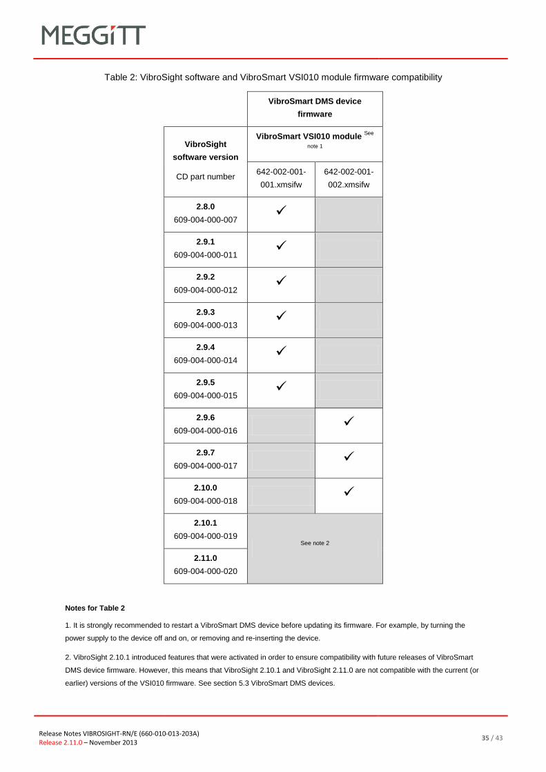
Release Notes VIBROSIGHT-RN/E (660-010-013-203A)
Release 2.11.0 – November 2013 35 / 43
Table 2: VibroSight software and VibroSmart VSI010 module firmware compatibility
VibroSmart DMS device
firmware
VibroSight
software version
CD part number
VibroSmart VSI010 module See
note 1
642-002-001-
001.xmsifw
642-002-001-
002.xmsifw
2.8.0
609-004-000-007
2.9.1
609-004-000-011
2.9.2
609-004-000-012
2.9.3
609-004-000-013
2.9.4
609-004-000-014
2.9.5
609-004-000-015
2.9.6
609-004-000-016
2.9.7
609-004-000-017
2.10.0
609-004-000-018
2.10.1
609-004-000-019 See note 2
2.11.0
609-004-000-020
Notes for Table 2
1. It is strongly recommended to restart a VibroSmart DMS device before updating its firmware. For example, by turning the
power supply to the device off and on, or removing and re-inserting the device.
2. VibroSight 2.10.1 introduced features that were activated in order to ensure compatibility with future releases of VibroSmart
DMS device firmware. However, this means that VibroSight 2.10.1 and VibroSight 2.11.0 are not compatible with the current (or
earlier) versions of the VSI010 firmware. See section 5.3 VibroSmart DMS devices.

36 / 43 Release Notes VIBROSIGHT-RN/E (660-010-013-203A)
Release 2.11.0 – November 2013
Table 3: VibroSight software and VibroSmart VSN010 device firmware compatibility
VibroSmart DMS device firmware
VibroSight
software version
CD part number
VibroSmart VSN010 device See note 1
642-004-001-
001.redboxfw
642-004-001-
002.redboxfw
642-004-001-
003.redboxfw
642-004-001-
005.redboxfw
2.8.0
609-004-000-007
2.9.1
609-004-000-011
2.9.2
609-004-000-012
2.9.3
609-004-000-013
2.9.4
609-004-000-014
2.9.5
609-004-000-015
2.9.6
609-004-000-016
2.9.7
609-004-000-017
2.10.0
609-004-000-018
2.10.1
609-004-000-019
2.11.0
609-004-000-020
Notes for Table 3
1. It is strongly recommended to restart a VibroSmart DMS device before updating its firmware. For example, by turning the
power supply to the device off and on, or removing and re-inserting the device.
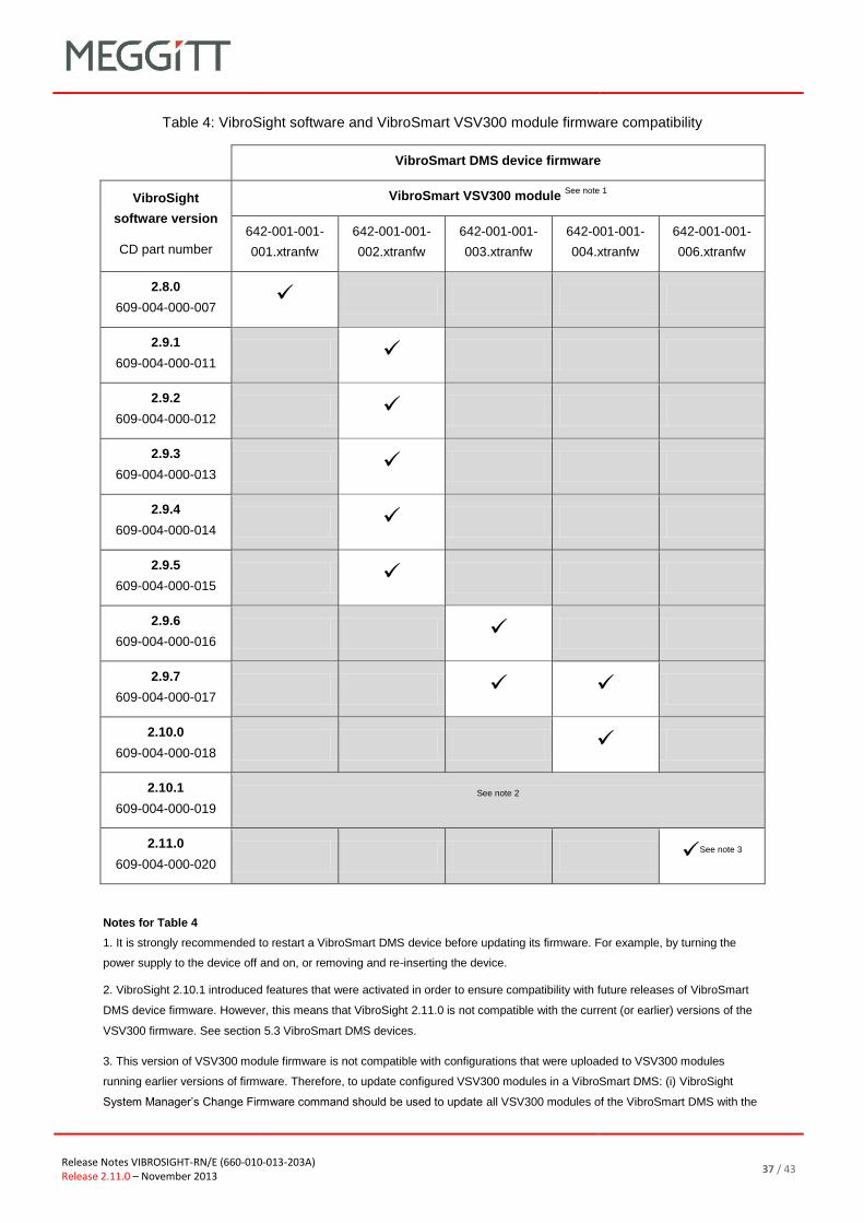
Release Notes VIBROSIGHT-RN/E (660-010-013-203A)
Release 2.11.0 – November 2013 37 / 43
Table 4: VibroSight software and VibroSmart VSV300 module firmware compatibility
VibroSmart DMS device firmware
VibroSight
software version
CD part number
VibroSmart VSV300 module See note 1
642-001-001-
001.xtranfw
642-001-001-
002.xtranfw
642-001-001-
003.xtranfw
642-001-001-
004.xtranfw
642-001-001-
006.xtranfw
2.8.0
609-004-000-007
2.9.1
609-004-000-011
2.9.2
609-004-000-012
2.9.3
609-004-000-013
2.9.4
609-004-000-014
2.9.5
609-004-000-015
2.9.6
609-004-000-016
2.9.7
609-004-000-017
2.10.0
609-004-000-018
2.10.1
609-004-000-019
See note 2
2.11.0
609-004-000-020
See note 3
Notes for Table 4
1. It is strongly recommended to restart a VibroSmart DMS device before updating its firmware. For example, by turning the
power supply to the device off and on, or removing and re-inserting the device.
2. VibroSight 2.10.1 introduced features that were activated in order to ensure compatibility with future releases of VibroSmart
DMS device firmware. However, this means that VibroSight 2.11.0 is not compatible with the current (or earlier) versions of the
VSV300 firmware. See section 5.3 VibroSmart DMS devices.
3. This version of VSV300 module firmware is not compatible with configurations that were uploaded to VSV300 modules
running earlier versions of firmware. Therefore, to update configured VSV300 modules in a VibroSmart DMS: (i) VibroSight
System Manager’s Change Firmware command should be used to update all VSV300 modules of the VibroSmart DMS with the
38 / 43 Release Notes VIBROSIGHT-RN/E (660-010-013-203A)
Release 2.11.0 – November 2013
new firmware (642-001-001-006.xtranfw), then (ii) VibroSight Configurator should be used to re-configure the VibroSmart DMS,
which will require a copy of the configuration. (Updating VSV300 modules that have not been configured simply requires that the
new firmware is uploaded to all VSV300 modules of the VibroSmart DMS and that the modules are subsequently configured
before use.)
6.4.3. Updating the firmware using VibroSight System Manager
When performing VibroSight software upgrades, it is strongly recommended to systematically upgrade
the firmware of VM600 XMx16 cards and VibroSmart DMS devices to the latest compatible version.
Failure to perform a necessary VibroSight-compatible VM600 card firmware update may lead to
incoherent system behaviour and affect the proper functioning of data acquisition in a system. It is only
in systems where the firmware running on the XMx16 cards and VibroSmart DMS devices already
corresponds to the latest available version that no firmware update is required. Therefore, it is strongly
recommended to verify the version of firmware running on the hardware before starting a VibroSight
system upgrade, in order to establish if a firmware update is also required.
NOTE: Changing the firmware of the VibroSight hardware is a special administrative task
that can – if performed unintentionally – affect the proper functioning of data
acquisition in a system.
It is therefore strongly recommended to change the firmware of the VibroSight
hardware only when it is necessary. For example, when the devices must be
updated to be compatible with a VibroSight software upgrade.
NOTE: It is strongly recommended to restart a VibroSmart DMS device before updating its
firmware. For example, by turning the power supply to the device off and on, or
removing and re-inserting the device.
Update the firmware on a VibroSight device using the Change Firmware tool (from VibroSight
System Manager’s Maintenance tools):
1. Ensure that the computer running the VibroSight software is on the same network as the
hardware (XMx16 card or VibroSmart DMS module or device) to be updated.
2. Start VibroSight System Manager and navigate to the Devices tree structure in the System
Explorer window.
The Devices tree lists all of the VibroSight compatible hardware that VibroSight can see on the
network. If there are no XMx16 cards or VibroSmart DMS devices in the tree structure or some
cards are missing, verify your network connections.
3. Select the card or device that requires its firmware to be changed.
The Actions tool window updates to show the available tools.

Release Notes VIBROSIGHT-RN/E (660-010-013-203A)
Release 2.11.0 – November 2013 39 / 43
4. Click Change Firmware in the Maintenance tools group of the Actions window.
The Change Firmware dialog box appears.
5. Click the Add button and select the new firmware files for the card or new firmware file for the
device.
NOTE: The Change Firmware dialog box automatically opens the firmware folder
corresponding to the VibroSight-compatible VM600 card or VibroSmart DMS
device selected.
.tgz files are for VM600 cards and .*fw files are for VibroSmart DMS devices.
6. Click the Finish button to start the firmware upgrade process.
For XMx16 cards and VibroSmart DMS devices, the firmware upgrade process can take up to
5 minutes, during which:
The IP address beside the device’s serial number in the Devices tree structure can
disappear.
The LEDs on the front panel of the device can change to reflect the status of the upgrade.
7. Repeat steps 3 to 6 for each device that requires a firmware update.
NOTE: Although the firmware for each VibroSight device must be changed individually
using the Change Firmware tool, as each device updates its firmware
independently of the VibroSight software (once the process has started), firmware
updates can be performed on several devices in parallel.
8. After the firmware upgrade, verify that the VibroSight system is acquiring data from the cards.
NOTE: Refer also to the Changing the firmware topics in the VibroSight help.
The Change Firmware tool can be used to load a VibroSight device with any version of
firmware. It is therefore possible to change a device’s firmware to any previously available version, as
well as the latest update.
This feature can be useful in certain situations, for example, swapping spare VibroSight hardware
between different VM600 racks or VibroSmart DMSs, where systems are operating with different
versions of VibroSight.
40 / 43 Release Notes VIBROSIGHT-RN/E (660-010-013-203A)
Release 2.11.0 – November 2013
6.5. Final checks
After upgrading the VibroSight software, the following checks are recommended to ensure that
VibroSight has not been inadvertently modified and that it continues to operate as expected:
Use VibroSight Configurator to run a consistency check on the configuration in order to ensure
that the configuration has not been modified by any changes to the VibroSight software,
internal database structure and firmware for the hardware (VM600 cards and VibroSmart DMS
modules).
Use the VibroSight Server window to check that the data acquisition, data post-processing and
data logging settings are as expected. (Click Data > Acquisition, Data > Post-processing
and Data > Logging and disable/enable the drivers, processing managers and logging as
required.)

Release Notes VIBROSIGHT-RN/E (660-010-013-203A)
Release 2.11.0 – November 2013 41 / 43
7. Customer support
7.1. Contacting us
Meggitt Sensing Systems worldwide customer support network offers a range of support including
Technical support and Sales and repairs support. For customer support, please contact your local
Meggitt Sensing Systems representative. Alternatively, contact our main office:
Customer support
Meggitt SA
Route de Moncor 4
PO Box 1616
CH-1701 Fribourg
Switzerland
Telephone: +41 (0) 26 407 11 11
Email: [email protected]
Web: www.meggittsensingsystems.com
7.2. Technical support
Meggitt Sensing Systems technical support team provide both pre-sales and post-sales technical
support, including:
General advice
Technical advice
Troubleshooting
Site visits.
7.3. Sales and repairs support
Meggitt Sensing Systems sales team provide both pre-sales and post-sales support, including advice
on:
New products
Spare parts
Repairs.
42 / 43 Release Notes VIBROSIGHT-RN/E (660-010-013-203A)
Release 2.11.0 – November 2013
Appendix

Release Notes VIBROSIGHT-RN/E (660-010-013-203A)
Release 2.11.0 – November 2013 43 / 43
VibroSight software and Windows operating system compatibility
Windows XP and
Windows Server 2003 R2
Windows Vista and
Windows Server 2008
Windows 7 and
Windows Server 2008 R2
Windows 8 and
Windows Server 2012
VibroSight software
compatible?
Yes, but not recommended for
new installations as Microsoft
support for Windows XP SP3
ends on 08 April 2014
Yes, but not recommended.
Windows Server 2008 R8
should be used instead of
Windows Server 2008
Yes – recommended for new
installations To be announced
Microsoft .NET Framework versions pre-installed on Windows operating systems
Windows XP and
Windows Server 2003 R2
Windows Vista and
Windows Server 2008
Windows 7 and
Windows Server 2008 R2
Windows 8 and
Windows Server 2012
Microsoft .NET Framework
pre-installed on Windows
operating system
None on XP.
.NET Framework 2.0 on
Server 2003 R2
.NET Framework 3.0 .NET Framework 3.0 SP1 .NET Framework 4.5
VibroSight software’s Microsoft .NET Framework requirements
VibroSight software version Windows XP and
Windows Server 2003 R2
Windows Vista and
Windows Server 2008
Windows 7 and
Windows Server 2008 R2
Windows 8 and
Windows Server 2012
VibroSight 2.9.1 or earlier .NET Framework 3.5 SP1 .NET Framework 3.5 SP1 .NET Framework 3.5 SP1 .NET Framework 3.5 SP1
VibroSight 2.9.2 and 2.9.3 .NET Framework 4 .NET Framework 4 .NET Framework 4 .NET Framework 4
VibroSight 2.9.4 or later .NET Framework 4 1 .NET Framework 4.5 .NET Framework 4.5 .NET Framework 4.5