vibration control of an artificial muscle manipulator with a
TRANSCRIPT

Journal of Physics Conference Series
OPEN ACCESS
Vibration control of an artificial muscle manipulatorwith a magnetorheological fluid brakeTo cite this article H Tomori et al 2013 J Phys Conf Ser 412 012053
View the article online for updates and enhancements
You may also likeOptimal design and torque control of anactive magnetorheological prosthetic kneeR M Andrade A Bento Filho C B SVimieiro et al
-
Design and testing of a regenerativemagnetorheological actuator for assistiveknee bracesHao Ma Bing Chen Ling Qin et al
-
Optimal design of a magneto-rheologicalbrake absorber for torsional vibrationcontrolQ H Nguyen and S B Choi
-
Recent citationsSensorless force control for dielectricelastomer transducersThorben Hoffstadt and Juumlrgen Maas
-
This content was downloaded from IP address 121299150 on 06122021 at 2341
Vibration control of an artificial muscle manipulator with a magnetorheological fluid brake
H Tomori13 Y Midorikawa1 and T Nakamura2 1Dept of Science and Engineering Chuo University 1-13-27 Kasuga Bunkyo-ku Tokyo Japan 2Chuo University 1-13-27 Kasuga Bunkyo-ku Tokyo Japan E-mail h_tomoribiomechchuo-uacjp Abstract Recently proposed applications of robots require them to contact human safely Therefore we focus on pneumatic rubber artificial muscle This actuator is flexible light and has high-power density However because the artificial muscle is flexible it vibrates when there is a high load Therefore we paid attention to the magnetorheological (MR) fluid We propose a control method of the MR brake considering energy of the manipulator system By this control method MR brake dissipates energy leading to vibration of the manipulator In this paper we calculated the energy and controlled the MR brake And we deliberated the proposal method by simulation using the dynamic model of the manipulator and experiment
1 Introduction Recently there have been advances in the development of partner robots aimed at providing life support and robots aimed at providing medical treatment and care such as power assistance [1] These robots are expected to be safe to human when these robots contact human Then we developed the straight-fiber-type artificial muscle [2] as actuators It has a high contraction percentage and high contractive force and this muscle has a long life compared with past McKibben type rubber artificial muscle [3-6] Moreover these artificial muscles are lightweight have high output and are flexible
However because the artificial muscle is flexible it vibrates when there is a high load Moreover the artificial muscle manipulator has a slow response because it is operated by air pressure and there is a limit to the response of the momentary power Therefore we are interested in the use of magnetorheological (MR) fluid [7] because its apparent viscosity can be changed very quickly (in milliseconds) by applying a magnetic field
Until now we have been developed a 1-degree-of-freedom artificial muscle manipulator using MR brake and controlled vibration of the artificial muscle by simple control of the MR brake However this control does not consider the characteristic of the manipulator As a result the MR brake interfered with the artificial muscle excessively
Thus in this paper we propose a control method of the MR brake considering energy of the manipulator system By this control method MR brake dissipates energy leading to vibration of the manipulator And we examine this proposal method by experiment and simulation using dynamic characteristic model of the manipulator 3Corresponding author
13th Int Conf on Electrorheological Fluids and Magnetorheological Suspensions (ERMR2012) IOP PublishingJournal of Physics Conference Series 412 (2013) 012053 doi1010881742-65964121012053
Published under licence by IOP Publishing Ltd 1
2 The straight-fiber-type artificial muscle The schematic of the artificial muscle developed at our laboratory is shown in figure 1 Table I shows the specifications of the artificial muscle used in this study The form of this artificial muscle is tubular and the material used is natural-rubber-latex liquid and carbon fiber Moreover since its structure includes a carbon fiber layer in the direction of an axis if air pressure is supplied to this artificial muscle the rubber membrane will expand but the fiber stops the growth in the direction of an axis so that the membrane is mostly not extended As a result the muscle expands only in a radial direction and contracts in the direction of an axis This artificial muscle is lightweight has high output and is flexible
Figure 1 A schematic diagram of the straight-fiber-type artificial muscle
Table 1 Specifications of artificial muscle
Length l [mm] 1870 The length between cap and ring l0 [mm] 623
Diameter d0 [mm] 123 Thickness t [mm] 023 Elastic modulus K [Pa] 800000 Number of rings 2
3 MR brakes We focused on the MR brake as a way to apply MR fluid to the joint We used the MRB-2107-3 of the LORD Co as MR braking equipment The overall view and the diagrammatic illustration of the MRB-2107-3 are shown in figure 2 And the characteristics of the MR brake are shown in figure 3 As figure 3 the MR brake changes apparent viscosity by magnetic field And relationship between its brake torque and rotational speed is low that it can ignore
This MR brake has high speed response in units of several milliseconds Thus we guess MR brake can control vibration of the arm of the manipulator This device generates friction on the surface of the disk as it changes in response to the magnetic field by arranging the MR fluid in the internal disk surroundings It is possible to apply brakes to a rotation operation according to this mechanism The MR brake has the following features
bull Since torque density is high it is small and it is high output bull Since the structure is simple it is strong bull The speed of response is in units of several milliseconds bull It can be changed continuously bull It is stable bull It is an energy-saving model
13th Int Conf on Electrorheological Fluids and Magnetorheological Suspensions (ERMR2012) IOP PublishingJournal of Physics Conference Series 412 (2013) 012053 doi1010881742-65964121012053
2
Figure 2 A configuration of MR brake
0123
45678
0 10 20 30 40 50 60 70
Torq
ue [N
m]
Rotational Speed [rpm]
00[V] 05[V] 10[V] 15[V] 20[V] 25[V]30[V] 35[V] 40[V] 45[V] 50[V]
Figure 3 Relationship between the rotational speed and the torque of MR brake
4 The artificial muscle manipulator with the MR brake Figure 4 shows the overall view of the developed one degree of freedom artificial muscle manipulator And Table 1 shows parameters of this manipulator The artificial muscle manipulator is arranged as two artificial muscles in parallel Further it transmits the contractile force of the artificial muscle to the rotation axis through the belt pulley The MR brake equipment is fixed to the first link side and it can apply braking power to the axis of rotation The manipulator is installed in the load cell to detect the load torque that hangs to the joint and the encoder to detect the joint angle
13th Int Conf on Electrorheological Fluids and Magnetorheological Suspensions (ERMR2012) IOP PublishingJournal of Physics Conference Series 412 (2013) 012053 doi1010881742-65964121012053
3
Figure 4 The artificial muscle manipulator with the MR brake
Table 2 Parameters of the artificial muscle manipulator
Mass of 2nd link M2 [kg] 0168 Length of 2nd link l [mm] 250 Center of gravity of 2nd link lrsquoG [mm] 240 Movable range θ [rad] -π2≦ θ≦ π6 Mass moment of inertia of 2nd link I1 [kgm2] 480times10-6
Parallel number of artificial muscles np 1
5 Manipulator model In this study we built a manipulator model for approach against control from theory However this system is difficult to reproduce as simple mass-spring-damper system because there is lateness of air pressure in this system Therefore we built a manipulator model while considering the dynamic characteristics of artificial muscles
The schematic view of this manipulator model is shown in figure 5 This model consists of three parts The first part is controller using a mechanical equilibrium model [2] treating the static characteristic of an artificial muscle Since the artificial muscles are highly nonlinear in contraction contractile force and pressure they are difficult to control This controller can linearize the characteristic of artificial muscles
The second part is a dynamic characteristics model containing the elements related to the dynamic characteristics of the air artificial muscle system As these elements the speed response of a solenoid valve the ease of passing of the air in an air tube the pressure change in an artificial muscle and the volume change in an artificial muscle are mentioned [8]
The third part is a load system model of the manipulator This model is based on forward dynamics These models were combined and considered as the manipulator model
13th Int Conf on Electrorheological Fluids and Magnetorheological Suspensions (ERMR2012) IOP PublishingJournal of Physics Conference Series 412 (2013) 012053 doi1010881742-65964121012053
4
Figure 5 A schematic of the manipulator mode
6 Calculation of energy for dissipation In this section we propose a control method considering mechanical energy in the manipulator system And a schematic diagram of joint manipulator is shown in figure 6 In this system load cells detect forces F1 and F2 These forces contain force for joint stiffness F0 force by load FL and elastic force Fe by inertia force of the arm
By the proposed method the MR brake dissipates energy leading to vibration of the arm of the manipulator Therefore we calculate kinetic energy of the arm and elastic energy of the artificial muscle Then we calculate brake torque of MR brake for dissipation of this mechanical energy
F0 F0F0 F0
Figure 6 Schematic diagram of joint manipulator
61 Kinetic energy Kinetic energy of the manipulator Wk is calculated by following equation Where I is Mass moment of inertia of the arm and θrsquo is angular velocity
13th Int Conf on Electrorheological Fluids and Magnetorheological Suspensions (ERMR2012) IOP PublishingJournal of Physics Conference Series 412 (2013) 012053 doi1010881742-65964121012053
5
2
21 θampIWk = (1)
62 Elastic energy The artificial muscles generate vibration because of own flexibility Therefore we control the vibration by dissipating elastic energy using MR brake Elastic energy of artificial muscles leading to vibration of the arm We calculated by following equation Where Ki is a spring constant of artificial muscles
21 eee WWW += (2)
2
21
iiei xKW = (3)
Next we calculated Ki The spring constant of artificial muscles Ki changes with pressure values linearly [2] Therefore each spring constant is calculated by the following formulas Where Pi is pressure and Kai are coefficients between stiffness and pressure of artificial muscles
iaii PKK = (4) Next we calculated displacement of artificial muscle xi from the spring constant of artificial
muscles and elastic force Fei
i
eii K
Fx = (5)
Where the artificial muscle manipulator is arranged two artificial muscles to parallel Further it transmits the contractile force of the artificial muscle to the rotation axis through the belt pulley Therefore force F1 and F2 detected by load cell contain 1 force for joint stiffness 2 load and 3 elastic force Thus for detection of elastic force we calculated difference of force F1 and F2 Thereby force for joint stiffness is eliminated
Le FFFF minusminus= 12 (6)
ee FF =1 (Fe gt 0) (7)
ee FF minus=2 (Fe lt 0) (8) Where FL is force of load calculated from mass of load M2 length of arm l radius of pulley r and
angle of the arm θ The elastic force Fe is pull force to the artificial muscles by inertia force of the arm This elastic force acts on one of artificial muscles or another by the movement direction of an arm as Fe1 or Fe2
rglMFL
θsin2= (9)
And we calculated We from (2) to (9)
⎟⎟⎠
⎞⎜⎜⎝
⎛+=
22
22
11
21
21
PKF
PKF
Wa
e
a
ee (10)
63 Dissipation energy of the MR brake In this section we calculated the dissipation energy by MR brake Wm Figure 7 shows the schematic view of the energy dissipation by MR brake Where θd is desirable angle of the arm In the proposed method we dissipate energy using MR brake in the area named dissipation section θα Changing θα
13th Int Conf on Electrorheological Fluids and Magnetorheological Suspensions (ERMR2012) IOP PublishingJournal of Physics Conference Series 412 (2013) 012053 doi1010881742-65964121012053
6
we can adjust dissipated energy From this figure the energy Wm calculated from brake torque τm and angular velocity
int= dtW mm θτ amp (11)
y
x
g
d
Wm
MR Brake
m
Figure 7 A schematic of the energy dispersion
And output torque of the MR brake τm is controlled for dissipation mechanical energy leading to
vibration Therefore τm is calculated by following equation
ekm WWW += (12)
int⎪⎭
⎪⎬⎫
⎪⎩
⎪⎨⎧
++
=dt
KF
KF
I ee
mθ
θ
τamp
amp
22
22
1
212
(13)
7 Vibration control experiment by the MR brake 71 Simulation for decision of energy dissipation section In this proposed method energy dissipated by MR brake depends on width of dissipation section θα Thus we need to decide width of energy dissipation section Therefore we deliberated the section using the dynamic model of the manipulator In this simulation desirable angle is 60 [deg] joint stiffness is 01 [Nmdeg] load is 96[N] and dissipation section is 10 [deg] to 40 [deg]
Figure 8 shows a result of simulation and figure 9 shows the amount of vibration and deviation area in each dissipation section In figure 9 Integration value of speed is defined as Integration value of the magnitude of the velocity vector of the arm This value becomes high when vibration of the arm increases Thus we used this value as evaluation of vibration of the arm Therefore we decided dissipate section so that integration value of speed and Difference area of position to step input become low In this study we attached weight to Integration value of speed Therefore we chose 30 [deg] as dissipation section
13th Int Conf on Electrorheological Fluids and Magnetorheological Suspensions (ERMR2012) IOP PublishingJournal of Physics Conference Series 412 (2013) 012053 doi1010881742-65964121012053
7
0
10
20
30
40
50
60
70
0 1 2 3 4 5 6Time [s]
Ang
le [d
eg]
Desirable angle θdNon_MR brakeθa=10θa=20θa=30θa=40
Figure 8 The simulation result (desirable angle is 60 [deg] joint stiffness is 01 [Nmdeg] and load is 96[N])
0
12
24
36
48
60
0
04
08
12
16
2
0 10 20 30 40 50
Diff
eren
ce a
rea
of p
ositi
on to
step
in
put[r
ad2 ]
Inte
grat
ion
valu
e of
spee
d [r
ads
]
Dissipation section θα [deg]
Integration value of speedDifference area of position to step input
Figure 9 Relationship between dissipation section and integration value of speed and difference area of position to step input
72 Vibration control experiment In this section we experiment to lift the arm with vibration control by proposed method In this experiment desirable angle θd is 60 [deg] joint stiffness is 01 [Nmdeg] load is 96[N] and dissipation section θα is 30 [deg] First the arm raises the load to the desirable angle Then energy dissipation is started 30 degrees before from the desirable angle Dissipated energy is calculated from sensor value in real time
A result of vibration control experiment and simulation is shown in figure 10 From This figure the dynamic model of the manipulator reproduces system of the manipulator in points of dead time rise time and motion of the arm And we conclude that the MR brake controls vibration of the arm successfully by proposed method from experimental result and simulation result And from figure 11 we confirmed that the mechanical energy in the vibration domain was dissipated
However there is response delay of MR brake because of coil in experimental result Thus we need to develop a driver for the MR brake
13th Int Conf on Electrorheological Fluids and Magnetorheological Suspensions (ERMR2012) IOP PublishingJournal of Physics Conference Series 412 (2013) 012053 doi1010881742-65964121012053
8
010203040506070
0 1 2 3 4 5 6Time [s]
Ang
le [d
eg]
Desirable angle θdNon_MR brakeθa=30 (simulation)θa=30 (experiment)
Figure 10 The experimental result (the dissipation section is 30 [deg])
0
04
08
12
16
0 1 2 3 4 5 6Time [s]
Ener
gy [J
] Non_MR brakeθa=30 (experiment)
Figure 11 The energy change of the manipulator when the energy dissipation is applied
8 Conclusion We proposed the energy dissipation method for control of the MR brake We calculated the energy leading to vibration and controlled the MR brake Then we applied the proposed method numerically using the dynamic model of the manipulator As a result we have shown that the MR brake controls vibration of the arm successfully by the proposed method We confirmed that the mechanical energy in the vibration domain was dissipated faster
For future works we plan to develop a MR brake driver to improve response of the MR brake In addition we develop a multi-DOF manipulator using MR brake
References [1] Satoh H Kawabata T Tanaka F and Sankai Y 2010 Transferring-care assistance with robot
suit HAL (Transactions of the Japan Society of Mechanical Engineers Series C) 76 227-35
13th Int Conf on Electrorheological Fluids and Magnetorheological Suspensions (ERMR2012) IOP PublishingJournal of Physics Conference Series 412 (2013) 012053 doi1010881742-65964121012053
9
[2] Nakamura T and Shinohara H 2007 Position and force control based on mathematical models of pneumatic artificial muscles reinforced by straight glass fibers Proc of IEEE Int Conf on Robotics and Automation ICRA (Roma Italy) pp 4361ndash66
[3] Gavrilovic M M and Maric M R 1969 Positional servo-mechanism activated by artificial muscles Medical and Biological Engineering 7 77ndash82
[4] Klute G K Czernieki J M and Hannaford B 1999 McKibben Artificial Muscles Pneumatic Actuators with Biomechanical Intelligence Proc of the IEEEASME Int Conf on Advanced Intelligent Mechatronics (Atlanta GA USA) pp 221ndash26
[5] Chou C P and Hannaford B 1994 Static and dynamic characteristics of McKibben pneumatic artificial muscles Proc of IEEE Int Conf On Robotics and Automation (San Diego CA USA) pp 281ndash86
[6] Nakamura T 2006 Experimental comparisons between McKibben type artificial muscles and straight fibers type artificial muscles SPIE Int Conf on Smart Structures Devices and Systems III (San Diego CA USA)
[7] Park B J Park C W Yang S W Kim H M and Choi H J 2008 Core-shell typed polymer coated-carbonyl iron suspension and their magnetorheology Int Conf on Electrorheological Fluids and Magnetorheological Suspensions ERMR08 (Dresden Germany) p 102
[8] Tomori H Midorikawa Y and Nakamura T 2010 Nonlinear dynamic characteristic model of artificial rubber muscle manipulator using MR brake Proc of the 12th Int Conf on Electrorheological Fluids and Magnetorheological Suspensions ERMR2010 (Philadelphia PA USA) pp 136-41
13th Int Conf on Electrorheological Fluids and Magnetorheological Suspensions (ERMR2012) IOP PublishingJournal of Physics Conference Series 412 (2013) 012053 doi1010881742-65964121012053
10
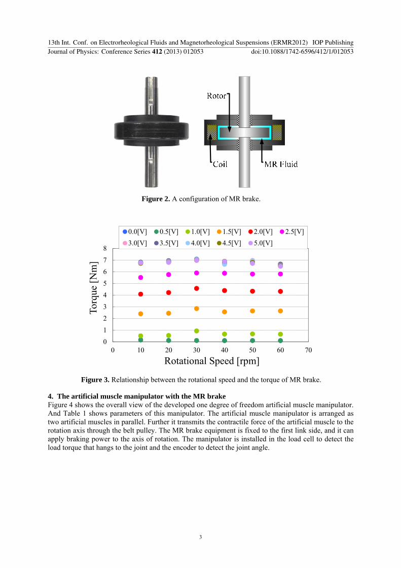

2
21 θampIWk = (1)
62 Elastic energy The artificial muscles generate vibration because of own flexibility Therefore we control the vibration by dissipating elastic energy using MR brake Elastic energy of artificial muscles leading to vibration of the arm We calculated by following equation Where Ki is a spring constant of artificial muscles
21 eee WWW += (2)
2
21
iiei xKW = (3)
Next we calculated Ki The spring constant of artificial muscles Ki changes with pressure values linearly [2] Therefore each spring constant is calculated by the following formulas Where Pi is pressure and Kai are coefficients between stiffness and pressure of artificial muscles
iaii PKK = (4) Next we calculated displacement of artificial muscle xi from the spring constant of artificial
muscles and elastic force Fei
i
eii K
Fx = (5)
Where the artificial muscle manipulator is arranged two artificial muscles to parallel Further it transmits the contractile force of the artificial muscle to the rotation axis through the belt pulley Therefore force F1 and F2 detected by load cell contain 1 force for joint stiffness 2 load and 3 elastic force Thus for detection of elastic force we calculated difference of force F1 and F2 Thereby force for joint stiffness is eliminated
Le FFFF minusminus= 12 (6)
ee FF =1 (Fe gt 0) (7)
ee FF minus=2 (Fe lt 0) (8) Where FL is force of load calculated from mass of load M2 length of arm l radius of pulley r and
angle of the arm θ The elastic force Fe is pull force to the artificial muscles by inertia force of the arm This elastic force acts on one of artificial muscles or another by the movement direction of an arm as Fe1 or Fe2
rglMFL
θsin2= (9)
And we calculated We from (2) to (9)
⎟⎟⎠
⎞⎜⎜⎝
⎛+=
22
22
11
21
21
PKF
PKF
Wa
e
a
ee (10)
63 Dissipation energy of the MR brake In this section we calculated the dissipation energy by MR brake Wm Figure 7 shows the schematic view of the energy dissipation by MR brake Where θd is desirable angle of the arm In the proposed method we dissipate energy using MR brake in the area named dissipation section θα Changing θα
13th Int Conf on Electrorheological Fluids and Magnetorheological Suspensions (ERMR2012) IOP PublishingJournal of Physics Conference Series 412 (2013) 012053 doi1010881742-65964121012053
6
we can adjust dissipated energy From this figure the energy Wm calculated from brake torque τm and angular velocity
int= dtW mm θτ amp (11)
y
x
g
d
Wm
MR Brake
m
Figure 7 A schematic of the energy dispersion
And output torque of the MR brake τm is controlled for dissipation mechanical energy leading to
vibration Therefore τm is calculated by following equation
ekm WWW += (12)
int⎪⎭
⎪⎬⎫
⎪⎩
⎪⎨⎧
++
=dt
KF
KF
I ee
mθ
θ
τamp
amp
22
22
1
212
(13)
7 Vibration control experiment by the MR brake 71 Simulation for decision of energy dissipation section In this proposed method energy dissipated by MR brake depends on width of dissipation section θα Thus we need to decide width of energy dissipation section Therefore we deliberated the section using the dynamic model of the manipulator In this simulation desirable angle is 60 [deg] joint stiffness is 01 [Nmdeg] load is 96[N] and dissipation section is 10 [deg] to 40 [deg]
Figure 8 shows a result of simulation and figure 9 shows the amount of vibration and deviation area in each dissipation section In figure 9 Integration value of speed is defined as Integration value of the magnitude of the velocity vector of the arm This value becomes high when vibration of the arm increases Thus we used this value as evaluation of vibration of the arm Therefore we decided dissipate section so that integration value of speed and Difference area of position to step input become low In this study we attached weight to Integration value of speed Therefore we chose 30 [deg] as dissipation section
13th Int Conf on Electrorheological Fluids and Magnetorheological Suspensions (ERMR2012) IOP PublishingJournal of Physics Conference Series 412 (2013) 012053 doi1010881742-65964121012053
7
0
10
20
30
40
50
60
70
0 1 2 3 4 5 6Time [s]
Ang
le [d
eg]
Desirable angle θdNon_MR brakeθa=10θa=20θa=30θa=40
Figure 8 The simulation result (desirable angle is 60 [deg] joint stiffness is 01 [Nmdeg] and load is 96[N])
0
12
24
36
48
60
0
04
08
12
16
2
0 10 20 30 40 50
Diff
eren
ce a
rea
of p
ositi
on to
step
in
put[r
ad2 ]
Inte
grat
ion
valu
e of
spee
d [r
ads
]
Dissipation section θα [deg]
Integration value of speedDifference area of position to step input
Figure 9 Relationship between dissipation section and integration value of speed and difference area of position to step input
72 Vibration control experiment In this section we experiment to lift the arm with vibration control by proposed method In this experiment desirable angle θd is 60 [deg] joint stiffness is 01 [Nmdeg] load is 96[N] and dissipation section θα is 30 [deg] First the arm raises the load to the desirable angle Then energy dissipation is started 30 degrees before from the desirable angle Dissipated energy is calculated from sensor value in real time
A result of vibration control experiment and simulation is shown in figure 10 From This figure the dynamic model of the manipulator reproduces system of the manipulator in points of dead time rise time and motion of the arm And we conclude that the MR brake controls vibration of the arm successfully by proposed method from experimental result and simulation result And from figure 11 we confirmed that the mechanical energy in the vibration domain was dissipated
However there is response delay of MR brake because of coil in experimental result Thus we need to develop a driver for the MR brake
13th Int Conf on Electrorheological Fluids and Magnetorheological Suspensions (ERMR2012) IOP PublishingJournal of Physics Conference Series 412 (2013) 012053 doi1010881742-65964121012053
8
010203040506070
0 1 2 3 4 5 6Time [s]
Ang
le [d
eg]
Desirable angle θdNon_MR brakeθa=30 (simulation)θa=30 (experiment)
Figure 10 The experimental result (the dissipation section is 30 [deg])
0
04
08
12
16
0 1 2 3 4 5 6Time [s]
Ener
gy [J
] Non_MR brakeθa=30 (experiment)
Figure 11 The energy change of the manipulator when the energy dissipation is applied
8 Conclusion We proposed the energy dissipation method for control of the MR brake We calculated the energy leading to vibration and controlled the MR brake Then we applied the proposed method numerically using the dynamic model of the manipulator As a result we have shown that the MR brake controls vibration of the arm successfully by the proposed method We confirmed that the mechanical energy in the vibration domain was dissipated faster
For future works we plan to develop a MR brake driver to improve response of the MR brake In addition we develop a multi-DOF manipulator using MR brake
References [1] Satoh H Kawabata T Tanaka F and Sankai Y 2010 Transferring-care assistance with robot
suit HAL (Transactions of the Japan Society of Mechanical Engineers Series C) 76 227-35
13th Int Conf on Electrorheological Fluids and Magnetorheological Suspensions (ERMR2012) IOP PublishingJournal of Physics Conference Series 412 (2013) 012053 doi1010881742-65964121012053
9
[2] Nakamura T and Shinohara H 2007 Position and force control based on mathematical models of pneumatic artificial muscles reinforced by straight glass fibers Proc of IEEE Int Conf on Robotics and Automation ICRA (Roma Italy) pp 4361ndash66
[3] Gavrilovic M M and Maric M R 1969 Positional servo-mechanism activated by artificial muscles Medical and Biological Engineering 7 77ndash82
[4] Klute G K Czernieki J M and Hannaford B 1999 McKibben Artificial Muscles Pneumatic Actuators with Biomechanical Intelligence Proc of the IEEEASME Int Conf on Advanced Intelligent Mechatronics (Atlanta GA USA) pp 221ndash26
[5] Chou C P and Hannaford B 1994 Static and dynamic characteristics of McKibben pneumatic artificial muscles Proc of IEEE Int Conf On Robotics and Automation (San Diego CA USA) pp 281ndash86
[6] Nakamura T 2006 Experimental comparisons between McKibben type artificial muscles and straight fibers type artificial muscles SPIE Int Conf on Smart Structures Devices and Systems III (San Diego CA USA)
[7] Park B J Park C W Yang S W Kim H M and Choi H J 2008 Core-shell typed polymer coated-carbonyl iron suspension and their magnetorheology Int Conf on Electrorheological Fluids and Magnetorheological Suspensions ERMR08 (Dresden Germany) p 102
[8] Tomori H Midorikawa Y and Nakamura T 2010 Nonlinear dynamic characteristic model of artificial rubber muscle manipulator using MR brake Proc of the 12th Int Conf on Electrorheological Fluids and Magnetorheological Suspensions ERMR2010 (Philadelphia PA USA) pp 136-41
13th Int Conf on Electrorheological Fluids and Magnetorheological Suspensions (ERMR2012) IOP PublishingJournal of Physics Conference Series 412 (2013) 012053 doi1010881742-65964121012053
10

0
10
20
30
40
50
60
70
0 1 2 3 4 5 6Time [s]
Ang
le [d
eg]
Desirable angle θdNon_MR brakeθa=10θa=20θa=30θa=40
Figure 8 The simulation result (desirable angle is 60 [deg] joint stiffness is 01 [Nmdeg] and load is 96[N])
0
12
24
36
48
60
0
04
08
12
16
2
0 10 20 30 40 50
Diff
eren
ce a
rea
of p
ositi
on to
step
in
put[r
ad2 ]
Inte
grat
ion
valu
e of
spee
d [r
ads
]
Dissipation section θα [deg]
Integration value of speedDifference area of position to step input
Figure 9 Relationship between dissipation section and integration value of speed and difference area of position to step input
72 Vibration control experiment In this section we experiment to lift the arm with vibration control by proposed method In this experiment desirable angle θd is 60 [deg] joint stiffness is 01 [Nmdeg] load is 96[N] and dissipation section θα is 30 [deg] First the arm raises the load to the desirable angle Then energy dissipation is started 30 degrees before from the desirable angle Dissipated energy is calculated from sensor value in real time
A result of vibration control experiment and simulation is shown in figure 10 From This figure the dynamic model of the manipulator reproduces system of the manipulator in points of dead time rise time and motion of the arm And we conclude that the MR brake controls vibration of the arm successfully by proposed method from experimental result and simulation result And from figure 11 we confirmed that the mechanical energy in the vibration domain was dissipated
However there is response delay of MR brake because of coil in experimental result Thus we need to develop a driver for the MR brake
13th Int Conf on Electrorheological Fluids and Magnetorheological Suspensions (ERMR2012) IOP PublishingJournal of Physics Conference Series 412 (2013) 012053 doi1010881742-65964121012053
8
010203040506070
0 1 2 3 4 5 6Time [s]
Ang
le [d
eg]
Desirable angle θdNon_MR brakeθa=30 (simulation)θa=30 (experiment)
Figure 10 The experimental result (the dissipation section is 30 [deg])
0
04
08
12
16
0 1 2 3 4 5 6Time [s]
Ener
gy [J
] Non_MR brakeθa=30 (experiment)
Figure 11 The energy change of the manipulator when the energy dissipation is applied
8 Conclusion We proposed the energy dissipation method for control of the MR brake We calculated the energy leading to vibration and controlled the MR brake Then we applied the proposed method numerically using the dynamic model of the manipulator As a result we have shown that the MR brake controls vibration of the arm successfully by the proposed method We confirmed that the mechanical energy in the vibration domain was dissipated faster
For future works we plan to develop a MR brake driver to improve response of the MR brake In addition we develop a multi-DOF manipulator using MR brake
References [1] Satoh H Kawabata T Tanaka F and Sankai Y 2010 Transferring-care assistance with robot
suit HAL (Transactions of the Japan Society of Mechanical Engineers Series C) 76 227-35
13th Int Conf on Electrorheological Fluids and Magnetorheological Suspensions (ERMR2012) IOP PublishingJournal of Physics Conference Series 412 (2013) 012053 doi1010881742-65964121012053
9
[2] Nakamura T and Shinohara H 2007 Position and force control based on mathematical models of pneumatic artificial muscles reinforced by straight glass fibers Proc of IEEE Int Conf on Robotics and Automation ICRA (Roma Italy) pp 4361ndash66
[3] Gavrilovic M M and Maric M R 1969 Positional servo-mechanism activated by artificial muscles Medical and Biological Engineering 7 77ndash82
[4] Klute G K Czernieki J M and Hannaford B 1999 McKibben Artificial Muscles Pneumatic Actuators with Biomechanical Intelligence Proc of the IEEEASME Int Conf on Advanced Intelligent Mechatronics (Atlanta GA USA) pp 221ndash26
[5] Chou C P and Hannaford B 1994 Static and dynamic characteristics of McKibben pneumatic artificial muscles Proc of IEEE Int Conf On Robotics and Automation (San Diego CA USA) pp 281ndash86
[6] Nakamura T 2006 Experimental comparisons between McKibben type artificial muscles and straight fibers type artificial muscles SPIE Int Conf on Smart Structures Devices and Systems III (San Diego CA USA)
[7] Park B J Park C W Yang S W Kim H M and Choi H J 2008 Core-shell typed polymer coated-carbonyl iron suspension and their magnetorheology Int Conf on Electrorheological Fluids and Magnetorheological Suspensions ERMR08 (Dresden Germany) p 102
[8] Tomori H Midorikawa Y and Nakamura T 2010 Nonlinear dynamic characteristic model of artificial rubber muscle manipulator using MR brake Proc of the 12th Int Conf on Electrorheological Fluids and Magnetorheological Suspensions ERMR2010 (Philadelphia PA USA) pp 136-41
13th Int Conf on Electrorheological Fluids and Magnetorheological Suspensions (ERMR2012) IOP PublishingJournal of Physics Conference Series 412 (2013) 012053 doi1010881742-65964121012053
10