vibration control of a coupled cylinder …eprints.utem.edu.my/16561/1/vibration control of a...
TRANSCRIPT
VIBRATION CONTROL OF A COUPLED CYLINDER UNDER
ROTATIONAL MOTION
JOSUA TAINSING
B041110233
BMCL
Email: [email protected]
Draft Final Report
Projek Sarjana Muda II
Supervisor: DR. ROSZAIDI RAMLAN
Faculty of Mechanical Engineering
Universiti Teknikal Malaysia Melaka
JUNE 2015
SUPERVISOR DECLARATION
“I hereby declare that I have read this thesis and in my opinion this report is sufficient in
terms of scope and quality for the award of the degree of
Bachelor of Mechanical Engineering (Plant & Maintenance)”
Signature: ...................................
Supervisor: Dr. Roszaidi Ramlan
Date: ...................................
i
VIBRATION CONTROL OF A COUPLED CYLINDER UNDER ROTATIONAL
MOTION
JOSUA TAINSING
This Report Is Submitted In Partial Fulfilment of Requirement For Degree of
Bachelor of Mechanical Enginering (Plant & Maintenance)
Faculty of Mechanical Engineering
Universiti Teknikal Malaysia Melaka
JUNE 2015
ii
DECLARATION
“I hereby declare that the work in this report is my own except for summaries and
quotations which have been dully acknowledge”
Signature: ...................................
Author: Josua Tainsing
Date: ...................................

iii
I dedicate my final year project to my family and my supervisor Dr. Roszaidi Ramlan. A
special feeling of gratitude to my loving parents, Tainsing Somundoh and Lotimah Sogiloi
whose encouragement and supported me throughout my degree. I will always appreciate all
they have done.

iv
ACKNOWLEDGEMENT
To the light, our God, who guided us through the way, to Dr. Roszaidi
Ramlan, for his great eforts of supervising and leading me to accomplish this fine
work. To my friends and families, they were a great source of support and
encouragement. Thank you.
v
ABSTRACT
In oil drilling process, one the most destructive element is vibration. The
phenomenon of vibration causes a lot of problem including drilling efficiency and
even safety of the operators. Vibration suppression in drilling has been an ongoing
study since years ago up until this century. Accurate prediction and controlling of
the vibration problem is essential to achieve a more efficient and safer drilling
operation. This research will focus on suppressing the vibration problem by studying
the vibration characteristic of different physical parameters of the coupled cylinder
and how to control them. Theoretical and experimental study was conducted to study
this vibration problem. Theoretical study involves the analysis about the equation of
motion of the coupled cylinder. The experimental study includes the investigation of
effect of different parameters in a coupled cylinder which include load, rotational
speed, cylinder’s length, eccentricity, misalignment and different type of coupling.
In this research, the line of drill pipes is characterized as coupled cylinder, the
linkage as coupling, the rotary table as motor, and the drilling mud as load. The
findings of this study lead to the understanding of the vibration characteristic of a
coupled cylinder and hence the identifying the effective control method.
vi
ABSTRAK
Dalam proses penggerudian minyak, salah satu elemen yang paling
merosakkan adalah getaran. Fenomena getaran menyebabkan banyak masalah
termasuk kecekapan penggerudian dan juga keselamatan pengendali. Penindasan
getaran dalam penggerudian merupakan satu kajian yang sedang berlangsung sejak
bertahun lalu sehingga abad ini. Ramalan yang tepat dan kawalanl masalah getaran
adalah penting untuk mencapai operasi penggerudian yang lebih cekap dan lebih
selamat. Kajian ini akan memberi tumpuan kepada mengurangkan masalah getaran
dengan mengkaji ciri-ciri getaran pada parameter fizikal yang berbeza bagi silinder
yang disambungkan dan bagaimana untuk mengawalnya. Kajian teori dan
eksperimen telah dijalankan untuk mengkaji masalah getaran ini. Kajian teori
melibatkan analisis tentang persamaan gerakan silinder yang disambung. Kajian
eksperimen termasuk penyiasatan kesan parameter yang berbeza di dalam silinder
yang disambung termasuk beban, kelajuan putaran, panjang silinder, kesipian, salah
jajaran dan jenis penyambung yang berbeza. Dalam kajian ini, talian paip gerudi
mempunyai ciri-ciri sebagai silinder yang disambumgkan pula, hubungan sebagai
penyambung, meja berputar sebagai motor, dan lumpur penggerudian sebagai beban.
Hasil kajian ini membawa kepada pemahaman ciri getaran silinder yang
disambungkan dan seterusnya mengenal pasti kaedah kawalan yang berkesan.
vii
TABLE OF CONTENTS
CHAPTER TITLE PAGE
PROJECT TITLE
DECLARATION
DEDICATION
ACKNOWLEDGEMENT
ABSTRACT
ABSTRAK
TABLE OF CONTENTS
LIST OF TABLES
LIST OF FIGURES
LIST OF SYMBOLS
LIST OF ABBREVIATIONS
i
ii
iii
iv
v
vi
vii
xi
xii
xvi
xviii
CHAPTER I INTRODUCTION
1.1 Problem Statement
1.2 Objective
1.3 Scope
1
1
2
2
CHAPTER II LITERATURE REVIEW
2.1 Fundamental of Vibration
2.2 Classification, Terminologies and
Quantification of Vibration
2.3 Vibration Analysis
2.3.1 Vibration Analysis Procedure
2.3.2 Vibration Sensors
2.4 Vibration of a Coupled Cylinder
Under Rotation Motion
2.4.1 Torsional Vibration
2.4.2 Lateral Vibration
3
3
4
6
6
7
9
12
13
viii
2.4.3 Misalignment and Unbalance
2.4.4 Eccentricity
2.5 Coupling
16
18
20
CHAPTER III METHODOLOGY
3.1 Analytical Study
3.2 Device Planning
3.3 Device Fabrication
3.4 Apparatus Preparation
3.5 Experimental Study
3.6 Collecting Data and Analysis
23
25
27
28
30
31
33
CHAPTER IV THEORETICAL ANALYSIS
4.1 Rotational Vibration
4.2 Radial Vibration
4.3 Fast Fourier Transform (FFT)
34
34
36
39
CHAPTER V DATA AND RESULT
5.1 Baseline Measurement
5.1.1 Motor Uncoupled
5.1.2 Rigid Shaft
5.2 Effect of Load and Rotational Speed to
Vibration Characteristic of Rotating Shaft
5.3 Effect of Shaft’s Length to Vibration
Characteristic of Rotating Shaft
5.4 Effect of Unbalance to Vibration
Characteristic of Rotating Shaft
5.5 Effect of Misalignment to Vibration
Characteristic of Rotating Shaft
5.6 Effect of Different Coupling to Vibration
Characteristic of Coupled Rotating Shaft
Under Different Condition
5.6.1 Effect of Different Coupling to
Vibration Characteristic of Coupled
43
43
44
47
51
55
60
64
68
ix
Rotating Shaft With and Without
Load
5.6.2 Effect of Different Coupling at
Different Location to Vibration
Characteristic of Coupled Rotating
Shaft
5.6.3 Effect of Different Coupling to
Vibration Characteristic of Coupled
Rotating Shaft Under Eccentric Load
5.6.4 Effect of Different Coupling to
Vibration Characteristic of Coupled
Rotating Shaft Under Misalignment
69
73
77
80
CHAPTER VI ANALYSIS AND DISCUSSION
6.1 Baseline Measurement
6.1.1 Motor Uncoupled
6.1.2 Rigid Shaft
6.2 Effect of Load and Rotational Speed to
Vibration Characteristic of Rotating Shaft
6.3 Effect of Shaft’s Length to Vibration
Characteristic of Rotating Shaft
6.4 Effect of Unbalance to Vibration
Characteristic of Rotating Shaft
6.5 Effect of Misalignment to Vibration
Characteristic of Rotating Shaft
6.6 Effect of Different Coupling to Vibration
Characteristic of Coupled Rotating Shaft
Under Different Condition
6.6.1 Effect of Different Coupling to
Vibration Characteristic of Coupled
Rotating Shaft With and Without
Load
6.6.2 Effect of Different Coupling at
83
83
83
84
85
86
87
88
89
89
x
Different Location to Vibration
Characteristic of Coupled Rotating
Shaft
6.6.3 Effect of Different Coupling to
Vibration Characteristic of Coupled
Rotating Shaft Under Eccentric Load
6.6.4 Effect of Different Coupling to
Vibration Characteristic of Coupled
Rotating Shaft Under Misalignment
90
91
91
CHAPTER IV CONCLUSION AND RECOMMENDATION
7.1 Conclusion
7.2 Recommendation
93
93
96
REFERENCES 97
xi
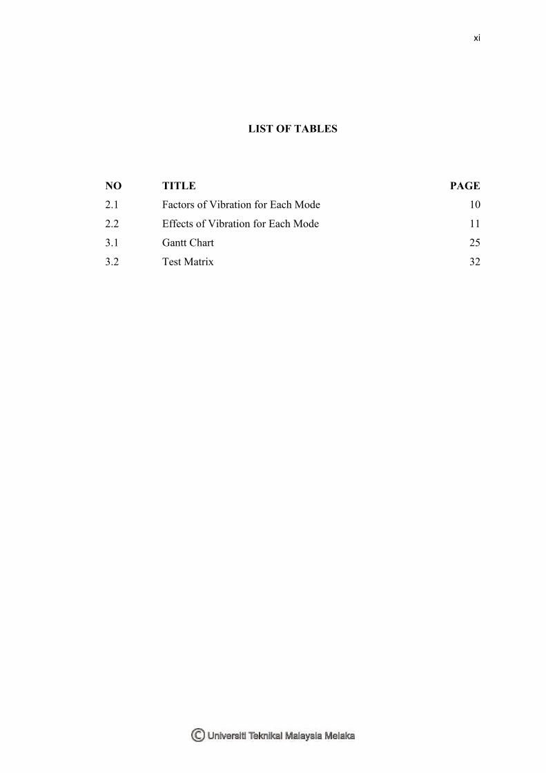
LIST OF TABLES
NO TITLE PAGE
2.1 Factors of Vibration for Each Mode 10
2.2 Effects of Vibration for Each Mode 11
3.1 Gantt Chart 25
3.2 Test Matrix 32

xii
LIST OF FIGURES
NO TITLE PAGE
2.01 Amplitude and Period of Sinusoidal Wave 4
2.02 Average, RMS and Peak of Sinusoidal Wave 5
2.03 Sensitivity of Sensors Over Different Frequency Range 8
2.04 Type of Drillstring Vibration 10
2.05 Mechanical Modeling of Torsional Vibration 13
2.06 Type of Whirl 14
2.07 Mechanical Modeling of Lateral Vibration 15
2.08 Parallel Misalignment Frequency Spectrum 16
2.09 Angular Misalignment Frequency Spectrum 17
2.10 Unbalance Frequency Spectrum 18
2.11 Two Types of Eccentricity 19
3.01 Flow Chart of Project 24
3.02 Flow Chart of Analytical Study 26
3.03 Disc Coupling 27
3.04 Jaw Coupling 27
3.05 Rubber Coupling 27
3.06 Apparatus Arrangement 28
3.07 Test Rig 29
3.08 Point of Measurement and Its sensor 30
3.09 Flow Chart of Experimental Study 31
3.10 Flow Chart of Data Collection and Analysis 33
4.01 Mechanical Modelling of Rotational Vibration 34
4.02 Displacement Transmissibility From Pipe 1 to Pipe 2 36
4.03 Mechanical Modelling of Lateral Vibration 37
4.04 Frequency Response Function 39
4.05 Example of FFT Transformation 39
xiii
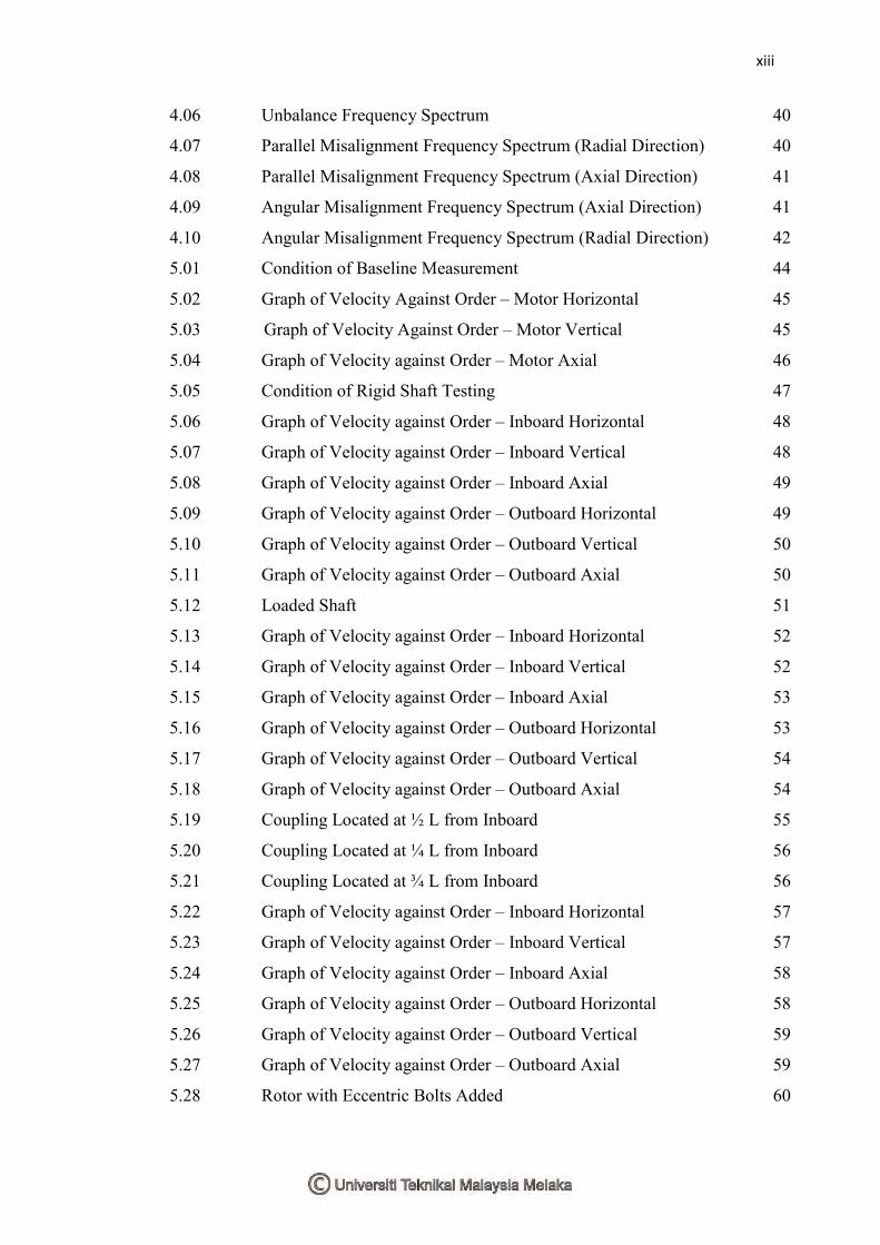
4.06 Unbalance Frequency Spectrum 40
4.07 Parallel Misalignment Frequency Spectrum (Radial Direction) 40
4.08 Parallel Misalignment Frequency Spectrum (Axial Direction) 41
4.09 Angular Misalignment Frequency Spectrum (Axial Direction) 41
4.10 Angular Misalignment Frequency Spectrum (Radial Direction) 42
5.01 Condition of Baseline Measurement 44
5.02 Graph of Velocity Against Order – Motor Horizontal 45
5.03 Graph of Velocity Against Order – Motor Vertical 45
5.04 Graph of Velocity against Order – Motor Axial 46
5.05 Condition of Rigid Shaft Testing 47
5.06 Graph of Velocity against Order – Inboard Horizontal 48
5.07 Graph of Velocity against Order – Inboard Vertical 48
5.08 Graph of Velocity against Order – Inboard Axial 49
5.09 Graph of Velocity against Order – Outboard Horizontal 49
5.10 Graph of Velocity against Order – Outboard Vertical 50
5.11 Graph of Velocity against Order – Outboard Axial 50
5.12 Loaded Shaft 51
5.13 Graph of Velocity against Order – Inboard Horizontal 52
5.14 Graph of Velocity against Order – Inboard Vertical 52
5.15 Graph of Velocity against Order – Inboard Axial 53
5.16 Graph of Velocity against Order – Outboard Horizontal 53
5.17 Graph of Velocity against Order – Outboard Vertical 54
5.18 Graph of Velocity against Order – Outboard Axial 54
5.19 Coupling Located at ½ L from Inboard 55
5.20 Coupling Located at ¼ L from Inboard 56
5.21 Coupling Located at ¾ L from Inboard 56
5.22 Graph of Velocity against Order – Inboard Horizontal 57
5.23 Graph of Velocity against Order – Inboard Vertical 57
5.24 Graph of Velocity against Order – Inboard Axial 58
5.25 Graph of Velocity against Order – Outboard Horizontal 58
5.26 Graph of Velocity against Order – Outboard Vertical 59
5.27 Graph of Velocity against Order – Outboard Axial 59
5.28 Rotor with Eccentric Bolts Added 60
xiv
5.29 Graph of Velocity against Order – Inboard Horizontal 61
5.30 Graph of Velocity against Order – Inboard Vertical 61
5.31 Graph of Velocity against Order – Inboard Axial 62
5.32 Graph of Velocity against Order – Outboard Horizontal 62
5.33 Graph of Velocity against Order – Outboard Vertical 63
5.34 Graph of Velocity against Order – Outboard Axial 63
5.35 Position of Inboard(left) and Outboard(right) for Misalignment
Test
64
5.36 Graph of Velocity against Order – Inboard Horizontal 65
5.37 Graph of Velocity against Order – Inboard Vertical 65
5.38 Graph of Velocity against Order – Inboard Axial 66
5.39 Graph of Velocity against Order – Outboard Horizontal 66
5.40 Graph of Velocity against Order – Outboard Vertical 67
5.41 Graph of Velocity against Order – Outboard Axial 67
5.42 Different Type of Coupling 67
5.43 Position of Coupling for With and Without Load Test 69
5.44 Graph of Velocity against Order – Outboard Horizontal 70
5.45 Graph of Velocity against Order – Outboard Vertical 70
5.46 Graph of Velocity against Order – Outboard Axial 71
5.47 Graph of Velocity against Order – Outboard Horizontal 71
5.48 Graph of Velocity against Order – Outboard Vertical 72
5.49 Graph of Velocity against Order – Outboard Axial 72
5.50 Coupling Located at ¼ L from Inboard 73
5.51 Coupling Located at ¾ from Inboard 74
5.52 Graph of Velocity against Order – Outboard Horizontal 74
5.53 Graph of Velocity against Order – Outboard Vertical 75
5.54 Graph of Velocity against Order – Outboard Axial 75
5.55 Graph of Velocity against Order – Outboard Horizontal 76
5.56 Graph of Velocity against Order – Outboard Vertical 76
5.57 Graph of Velocity against Order – Outboard Axial 77
5.58 Coupled Shaft Wit Eccentric Bolt Attached 78
5.59 Graph of Velocity against Order – Inboard Horizontal 78
5.60 Graph of Velocity against Order – Inboard Vertical 79
xv
5.61 Graph of Velocity against Order – Inboard Axial 79
5.62 Position of Inboard(left) and Outboard(right) for Misalignment Test
80
5.63 Graph of Velocity against Order – Outboard Horizontal 81
5.64 Graph of Velocity against Order – Outboard Vertical 81
5.65 Graph of Velocity against Order – Outboard Axial 82
xvi
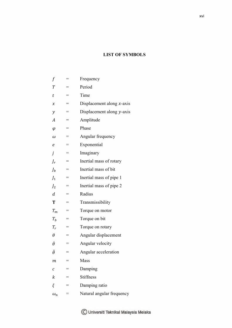
LIST OF SYMBOLS
= Frequency
= Period
= Time
= Displacement along -axis
= Displacement along -axis
= Amplitude
= Phase
= Angular frequency
= Exponential
= Imaginary
= Inertial mass of rotary
= Inertial mass of bit
= Inertial mass of pipe 1
= Inertial mass of pipe 2
= Radius
= Transmissibility
= Torque on motor
= Torque on bit
= Torque on rotary
= Angular displacement
= Angular velocity
= Angular acceleration
= Mass
= Damping
= Stiffness
= Damping ratio
= Natural angular frequency
xvii
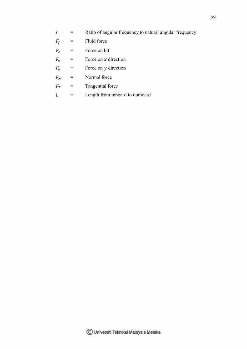
= Ratio of angular frequency to natural angular frequency
= Fluid force
= Force on bit
= Force on direction
= Force on direction
= Normal force
= Tangential force
= Length from inboard to outboard
xviii
LIST OF ABBREVIATIONS
RMS - Root mean square
BHA - Bottom hole assembly
ROP - Rate of penetration
PDC - Polycrystalline diamond compact
1
CHAPTER I
INTRODUCTION
This research is about the study of vibration control of a coupled cylinder
under rotational motion as faced in oil drilling process. Oil drilling process is prone
to many types of vibration problem. This research will lead to the understanding of
the vibration problem and how to control them.
1.1 Problem Statement
The line of drill pipes in oil drilling process is subjected to three modes of
vibration which are axial, radial and torsional. The real situation in oil drilling
process was imitated in laboratory, where the rotary table, drill pipe, connection and
drilling mud is characterised as the motor, cylinder or shaft, coupling and load
respectively.
Axial vibrations, is a motion along the lengthwise axis of the cylinder. In
drilling process, this is mostly due to the interaction between drilling bit and the hole
bottom. This vibration is called ‘‘bitbounce’’. Axial vibration was introduced by
introducing angular misalignment as this type of misalignment tends to create a
strong vibration in axial direction.
Lateral vibrations, often caused by pipe eccentricity, leading to centripetal
forces during rotation, named as drillstring whirl. This problem was imitated in the
2
laboratory by introducing eccentric mass at the rotating coupled cylinder. Eccentric
mass will generate centrifugal force which is in radial or lateral direction.
Torsional or rotational vibrations caused by nonlinear load magnitude. The
rotational vibration of the cylinder characterized by alternating stops during which
the pipe sticks and intervals of large angular velocity of the pipe. However, due to
equipment availability restriction in the laboratory, only analytical analysis was
conducted for this type of vibration.
Different physical parameters of the oil drilling equipment were also studied.
That includes the effect of different parameters in a coupled cylinder which include
load, rotational speed, cylinder’s length, and different type of coupling.
1.2 Scope
The problem imitates the real problem during oil drilling process. Involve
theoretical mechanical modelling of the dynamics of the coupled cylinders. A test
will be fabricated and tested. The study will lead to understanding of what governs
the good vibration control properties of the coupled structure. The study will also
gain knowledge on how to control the vibration.
1.3 Objective
1. To study the vibration characteristics of a coupled cylinder.
2. To study the effect of coupling mechanism and how to control the vibration at
the coupling.
3. To fabricate a test rig to investigate the vibration characteristic of coupled
cylinder and performance of coupling.
3
CHAPTER II
LITERATURE REVIEW
In this chapter, all of information related to vibration analysis and control that
used for the study of vibration characteristic of coupled cylinder under rotational
motion was elaborated. Literature review is important process to get all information
related to this research.
2.1 Fundamental of Vibration
According to Putra (2013a), Vibration is the motion of a particle or a body
from a position of equilibrium. Vibration occurs when a system is moved from
equilibrium position. The system will return to equilibrium position under the action
of restoring forces such as the elastic forces, as for a mass attached to a spring, or
gravitational forces, as for a simple pendulum. The system keeps moving back and
forth across the equilibrium position.
Most vibrations are undesirable in machines and structures because they
produce increased stresses, energy losses, causes added wear, increase bearing loads,
induce fatigue, create passenger discomfort in vehicles, and absorb energy from the
system. Vibration causes noise which creates discomfort and annoyance to human.
In some field, vibration is found to be beneficial such as in tooth cleaning, massage
chair, music instrument and energy harvesting.
Vibration is due to imperfection in machine or structure. The possible factors
are imperfection in design process. Defect in manufacturing, installation or assembly
cause the machine or structure to vibrate. Improper operation and maintenance also
4
cause vibration problem. Rotating machines need proper balancing in order to
prevent damage from vibrations.
2.2 Classification, Terminologies and Quantification of Vibration
Vibrations can be classified into three categories which are free, forced, and
self-excited. Free vibration occurs with the absence of external force in the system.
An external force that acts on the system causes forced vibrations. In this case, the
exciting force continuously supplies energy to the system. Self-excited vibrations are
periodic and deterministic oscillations. In contrast to forced vibrations, the exciting
force is independent of the vibrations and can still persist even when the system is
prevented from vibrating.
Below are some basic terminologies in vibration (Putra 2013b):
Mass - store of kinetic energy
Stiffness - store of potential (strain) energy
Damping - dissipate energy
Force - provide energy
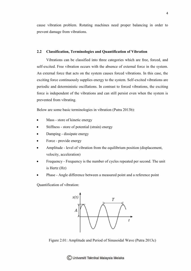
Amplitude - level of vibration from the equilibrium position (displacement,
velocity, acceleration)
Frequency - Frequency is the number of cycles repeated per second. The unit
is Hertz (Hz)
Phase - Angle difference between a measured point and a reference point
Quantification of vibration:
Figure 2.01: Amplitude and Period of Sinusoidal Wave (Putra 2013c)