vibration and operation technical consideration before ...4)13/3.pdf · technical document.high...
TRANSCRIPT

American-Eurasian Journal of Scientific Research 8 (4): 163-183, 2013ISSN 1818-6785© IDOSI Publications, 2013DOI: 10.5829/idosi.aejsr.2013.8.4.1120
Corresponding Author: Omid Ali Zargar, Department of Mechanical Engineering-jawaharlal Nehru Technological UniversityHyderabad, Kukatpally, Hyderabad-500085, Andra Pradesh, India.
163
Vibration and Operation Technical ConsiderationBefore Field Balance of Gas Turbine Utilities
Omid Ali Zargar
Department of mechanical engineering - Jawaharlal Nehru technological university Hyderabad,Kukatpally, Hyderabad-500085, Andra Pradesh, India
Abstract: one of the most challenging time in operation of big industrial plant or utilities is the time that alertlamp of bently Nevada connection in main board substation turn on and show the alert condition all of themaintenance groups usually make a lot of discussion. with operation and together rather this alert signal is realor fake this will be more challenging when condition monitoring vibration data shows 1X in fast Fouriertransform (FFT) and vibration phase trends show 90 degree shift between two non-contact probe directionsin recent days and CM group suspicious about unbalance rotor in this paper firs I try to introduce recentpatent and innovation in balancing technologies and tools it can help the readers that not too much involveto preventive maintenance directly, to better understanding the balancing process on the other hand the readerswho involve the vibration concept also can be more familiar to new data collectors related to balancing processand their new capabilities and options beside this I will introduce some recent more challenging case historyin field balance of gas turbines(2012-2013).these processes will help us to evaluate the evidences that can helpus to better understanding of machine condition in alert time and cause make better decision to let the machineto continue running or operate the balancing or any other maintenance action in further applications.
Key words: Gas turbine Field balance Turbine compressors Balancing machine Balancing tools Balancing data collectors Utility Digital signal processor APT Software Condition
monitoring Non-contact probe
INTRODUCTION machining tools, and aircraft gas turbine engines.
The condition monitoring system of most critical in rotating machinery. Imbalance occurs if the principalequipment is one of the major important topic in axis of inertia of the rotor is not coincident with itspreventive maintenance, Bentley Nevada systems widely geometric axis.develop in recent years and the option and capabilities of Higher speeds cause much greater centrifugaldata collector improve so much also up to date almost imbalance forces, and the current trend of rotatingevery year the unbalance recommendation by condition equipment toward higher power density clearly leads tomonitoring group usually accrue when the alert condition higher operational speeds. Therefore, vibration control isappear in bently Nevada board in operation main board essential in improving machining surface finish; achievingsubstation with three main vibration behavior of the longer bearing, spindle, and tool life in high-speedrotor first two direction of non-contact probe vibration machining; and reducing the number of unscheduled(X and Y) both considerably high in recent days shutdowns [2].secondly the main peak in fast Fourier transform (FFT) is The small or medium size rotor usually send to1X and the other peaks are not too much or considerable balance shop more easily because they are more easy tofinally vibration phase trends show 90 degree shift carry them to balance shop on the other hand the big orbetween two non-contact probes directions in recent long rotors just will send to balance shop in criticaldays [1]. Rotating machinery is commonly used in operation condition. that is why main plant usually havemechanical systems, including industrial turbo-machinery, central balance shop inside factory in the balance shop
Vibration caused by mass imbalance is a common problem

Am-Euras. J. Sci. Res., 8 (4): 163-183, 2013
164
we have the wide type of balancing machines firstclassified by hard bearing and soft bearings typebalancing machine the second consideration is due toflexible and rigid rotors the rotor of most criticalequipment usually flexible and more challenging forbalance the other consideration in length of the rotor themain balance shops and balance shops related to the main Fig. 1: Type 7790-A Two-plane Balancing Consultantworkshop of big plants usually equipped with wide and Type 7790 page.sufficient types of balancing machine also there aredifferent type of balancing machine related to overhang flexible rotor usually balance in two or more panel foror middle hang rotor the most critical equipment usually better balance quality.Beside this there are a number ofmiddle hang [3]. valuable information about other stage of balancing
Beside this the rotor RPM is one of the most procedure in machine technical documents. The fieldimportant consideration in balancing process the RPM of balance process is also apply with different software andbalancing process is directly related to amount of rotor data collector with different options, quality, accuracy andRPM and usually much fewer and introduce in machine capabilities [8] in this section I am trying to introducetechnical document.high speed rotor balance is usually recent patent and innovation in balancing data collectorone of the most challenging balancing process in balance capabilities and options. this process also will help betterworld and need special balancing machine and equipped understanding of the balance procedure and options.balance shops [4]. high speed balance is one of the newer One of the recent patent in new balancing databalance techniques that developed by modern balancing collector and soft wares is Balancing - Type 7790-A.machines. There are numerous advantages to high-speed Two-plane Balancing Consultant Type 7790-A is anbalancing of generator and turbine rotors. These include, intuitive and effective tool for in-site (field) single-planeSmooth operation through the entire speed range up to and two-plane balancing of rotating machinery inover speed, The ability to access optimal weight planes, Two-plane Balancing method The experimental frequencywhich are not normally accessible during operation in the spectrum usually obtain for both baseline andmachine, Verification of the mechanical integrity of the unbalanced condition under different unbalanced forces.rotor and any assembled components, up to over speed And The experimental results of balanced and unbalancedand Electrical testing of generator rotors through their rotors are compared at two different rotor locations [9].entire speed range can identify the existence of any speed Multiplane Balancing Consultant Type 7790-B addsrelated electrical faults. Also, long and slender rotors may three and four-plane balancing. A task-oriented usernot be able to be balanced with the planes available in the interface guides you quickly and safely through thefield due to the reduced influence of these areas on the necessary steps for setting up, measuring, validating andunbalance in the rotor. In general, rotors that have had a reporting. Fast trim balancing using stored rotor data ischange in their mechanical condition are best suited for a also supported [10]. The balance quality can behigh speed balance [5] also the sensor of the balancing determined according to established balance qualitymachine have two main groups first that work with the grades (ISO1940.1) or according to maximum machineprincipal of vibration measurement and the second vibrations. The balancing procedure can be FFT-based orcategory is whom base on force measurement the main based on order tracking for the most accurate results.difference is balancing process the second type is less The most important features divided in severaltime consuming and usually need only a few try and error categories like, Task-oriented user interface that guidesprocedure but these kind of balancing machine develop you through all the stages of a balancing measurement,just for rigid rotor and not applied with most critical Balancing based on phase-assigned spectra, FFT-basedequipment [6]. The grade of a balance is a number that will balancing method for standard balancing on machinescalculate with the balancing engineer due to the technical with stable speed, Order tracking-based balancingdocuments of the rotor like material, geometry and weight method for complex balancing on machines withthe grade of the balance will help the balance engineer to unstable speed (requires Order Analysis Type 7702),choose the most suitable balancing machine for the Balance quality according to established gradesbalance process [7]. Figure 7 will help to better (ISO 1940.1) or maximum machine vibrations, Alarms forunderstanding of some types of industrial rotors also the excessive vibration levels and speed, 3D rotor geometry

Am-Euras. J. Sci. Res., 8 (4): 163-183, 2013
165
illustrations for easy overview of measuring planes and assembly errors, and especially faults occurring duringcorrection planes, 2D graphical views of correction operation of the machine. By reducing these vibrations,planes with weight positions and of measuring planes better performance and more cost-effective operation canwith transducer positions,RPM meter with analog and be achieved and deterioration of the machine anddigital read-outs, service speed range and maximum ultimately fatigue failure can be avoided. This requires theallowable speed, Display of triggered tacho signal for rotor to be balanced by adding and/or removing mass atoptimal settings of tacho detection parameters, Display certain positions in a controlled manner.Two-planeof vibration time signals and spectra, Vector polar plots Balancing Consultant Type 7790A supports single-planeof fundamental frequency/1st order, Indication of initial, and two-plane balancing with determination oftrial, final and optimization run results in vector polar balance quality according to ISO 1940–1. The balancingplots, Tables of measurement results and applied masses, process is performed as in site balancing (field balancing)Weight splitting for use of standard masses and/or where the rotor is balanced in its own bearings andpredefined mass positions, Support of predefined, distinct supporting structure, rather than in a balancingmasses for simplified input, Fast direct print of reports in machine. Trim balancing, using stored rotor datapredefined layout, Reporting using Microsoft and Word (influence coefficients) from previous balancingin predefined layout or formatted according to ISO 20806, sessions is also supported, ensuring fast correction ofVibration as displacement, velocity or acceleration and small residual unbalances in cases where balancingSupport of both SI and Imperial units.these kind of has to be repeated. The Balancing Consultant has anmodern data collector have a vide application in new intuitive, task-oriented, graphical user interfacetechnological industries specially in field balance of gas leading you quickly through the necessary tasks forturbines. and also in other type Dynamic, in-site balancing setup, measurement and reporting.Balancing can beof rotating machinery,Trim balancing using stored rotor based on either frequency spectra (FFT) or order spectradata (influence coefficients) from previous balancing (order tracking). Traditional FFT-based balancing ismeasurements and alsoPart of complete solutions for sufficient in many measurement situations. However, inrotating machinery analysis and machine diagnostics cases with unstable machinery speed and/or highincluding, Measurement transducers and accessories and frequency resolution requirements, order tracking shouldConditioning, measurement and analysis using the PULSE be used to eliminate frequency smearing and provide moremulti-analyzer system.Unbalance is a result of uneven accurate results.Balancing using order tracking requiresdistribution of a rotor’s mass and causes vibration to be Order Analysis Type 7702. As Balancing and Ordertransmitted to the bearings and other parts of the Analysis address the same kind of machinery, themachine during operation. Imperfect mass distribution can hardware accessories for the two configurations are alsobe due to material faults, design errors, manufacturing and the same.
Fig. 2: The rotor’s geometry and the available mass positions on the correction planes are easily defined using 2D and3D geometries. Various one and two plane rotor types are supported.

Am-Euras. J. Sci. Res., 8 (4): 163-183, 2013
166
Fig. 3: The measurement is controlled using a Guide with controlled status indication. An RPM meter checks the speedand vector plots.
Fig. 4: BM Console (VMI) instruments to improve the performance of older
Fig. 5: Measuring unit with transducer/sensor interface for any asynchronous AC electrical motor with powerand digital signal processor. from 1.1 kW to 15kW.the most important advantages of
The most important advantages of this balancing this equipment is easy to use and is user friendly but it ismachine is its accuracy and its wide technical options that not suitable for field balancing activities because it is acan help the balancing engineers in complex balancing kind of stationary balancing machine and not portable foractivities with more technical flexibility. BM Console also site activities.
is another data collector related to balancing activitiesrecently introduce to preventive maintenance world byVMI company. The BM Console is a complete instrumentfor balancing rotating equipment on a balancing machine.A wide range of features are available to cover all therequirements of precision balancing, includingcomparison to established tolerances and printing acertificate to document the balancing result. The touchactivated, LCD screen allows quick data entry and menuselection. Screen prompts and online help files assist theoperator in obtaining fast and accurate results. Polar orlarge digital displays are available to provide the operatorwith a graphic representation of the balance vectors.The BM Console can be used for replacing older
machines.The BM Console electronics, based on aPentium processor and a APT326 Balancing Interface,provides a wide range of balancing speeds, highmeasurement accuracy and signal filtering. The BMConsole has four parts, 15" LCD Display with TouchScreen, Single Board computer running Windows XP andAPT300 software, APT326 Balancing Interface Board anda mounting plate to be used to place a Speed Controller
this data collector related to balancing activities is that

Am-Euras. J. Sci. Res., 8 (4): 163-183, 2013
167
APT 326 is also one of new modern data collectors APT Software have also some special characteristicrelated to the balancing process manufactured by VMI first software have Flexible inputs. The program can beused for both field balance and balance shop applications controlled either by a mouse, the function buttons F1- F10the software options is user friendly and easy to use or with the use of the touch screen. Most of therather than other types of equipment. Functions indicate measurements and calculations are made in theas, Balancing with two transducers simultaneously, measuring unit so the demand on the PC-computer isRS232 communication with PC software, Suitable as limited. The software can run on almost any PC.instrument update of older balancing machines, Large Beside this software can Starts and saves automatically.speed range. Balancing can be made between 30 to 192 The program both starts and finishes the measurements000 rpm depending on transducer choice, CD with a with trial and balancing weights automatically. Acomplete balancing program and The program has several measurement starts automatically when the selectedbuilt in languages. balancing RPM has been obtained and finishes
APT 326 have several options like Acceleration, automatically when the measurements are stable. A builtvelocity and displacement transducers, Transducer in relay can automatically stop the machine when thecables and Encoder for angle positioning of balancing measurements are saved. Furthermore The program canweights. store the balancing under different file names in a
The APT Software related to APT 326 balancing tool balancing library. The sensitivity to an unbalance is alsohave special option and characteristic that make this tool stored as the Response Matrix that can be used nexteasier to use comparative to previous tools or balancing time the same or a similar rotor has to be balanced.data collectors. firstly The program can be controlled The software then calculates the balancing weightseither by a mouse, the function buttons F1- F10 or with directly without the need for trial weights and trial runs.the use of the touch screen. Most of the measurements Specially made shafts must sometimes be used when onlyand calculations are made in the measuring unit so the a part of a rotor is balanced, for example only a fan wheel.demand on the PC-computer is limited. The software can The unbalance in these shafts can be stored in the Toolrun on almost any PC. Secondly The program both starts library. When the fan wheel is balanced the unbalance inand finishes the measurements with trial and balancing the“tool” shaft is then automatically reduced from theweights automatically. A measurement starts measured vibrations. Finally The unit for vibration canautomatically when the selected balancing RPM has been instantly be change between mm/s or µm and the unit forobtained and finishes automatically when the unbalance can be change between grams or gram as wellmeasurements are stable. A built in relay can as the change between static and coupled and normal leftautomatically stop the machine when the measurements and right unbalance.are saved. Beside this The program can store the The most important comfortable features of this toolbalancing under different file names in a balancing library. related to previous options is Weight distribution to fixedThe sensitivity to an unbalance is also stored as the positions The program can distribute the balancingResponse Matrix that can be used next time the same or weight to fixed positions e.g. to bolts in a coupling or toa similar rotor has to be balanced. The software then blades in a fan. this feature can reduce the volume of trycalculates the balancing weights directly without the need and error process in balancing activities. another featuresfor trial weights and trial runs. Specially made shafts must is Weight summations, If a rotor has several old balancingsometimes be used when only a part of a rotor is weights the program can calculate one weight as abalanced, for example only a fan wheel. The unbalance in replacement for all the other weights.these shafts can be stored in the Tool library. When the The people that directly involve in balancingfan wheel is balanced the unbalance in the “tool” shaft is activities know how much in can help to the balancingthen automatically reduced from the measured vibrations. process time and reduce the trouble because the rotorsFinally The unit for vibration can instantly be change that have recommend for balancing by CM (conditionbetween mm/s or µm and the unit for unbalance can be monitoring ) groups usually are bad actor in this area andchange between grams or gram as well as the change previously several balancing process and severalbetween static and coupled and normal left and right balancing weights are added to the rotor that some timeunbalance. need to eliminating by some machining process all in all

Am-Euras. J. Sci. Res., 8 (4): 163-183, 2013
168
Fig. 6: Typical APT Software page
this option that developed in recent years helping to unbalance is one of the most challenging concepts inreduce the balancing process time considerably and more preventive maintenance the alignment have usuallycomfortable. Remember always it is important to input the complex procedure for most critical equipment the phasedimension of rotors accurately during the balancing analysis between two side of coupling could help us toprocess it can cause better balancing quality the typical have better understanding about balance condition of therotors that may balance by field balance or balancing in coupling nowadays different methods develop forbalance shop are shown in typical APT Software page evaluating and modeling the coupling motion all baseshown in Figure 6. [11, 12]. on vibration modal analysis [14] also the shaft crack is
Experimental Detail: In this paper I decide to explain 4 critical equipment that is hard to diagnosis the crack couldseparate case history about vibration and operation be longitudinal or radial and usually in microscopicbehavior of gas turbine SIEMENS162MW- V94.2.for this dimensions the bode diagram could help us in faultpurpose firstly I had to talking about these kind of turbine diagnosis monitoring of coast down and run uptechnical specification. V94.2 Gas Turbine Features characteristics when passing through resonancerepresent in Figure 8. (rotor critical speed) is the optimal way for fault diagnosis
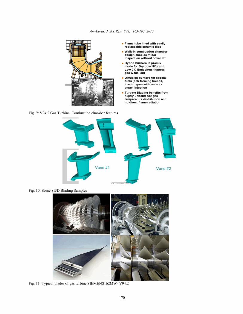
V94.2 Gas Turbine Combustion chamber features the cracked rotors usually sent to metal spray work shopalso represent in Figure 9. for treatment activities [15] the lubrication system of most
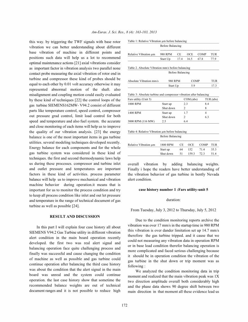
The blading system is SI3D as the following photo critical equipment is also one of the most challengingdescription for vane #1 and vane #2. concept in this matter the centrifugal pumps usually feed
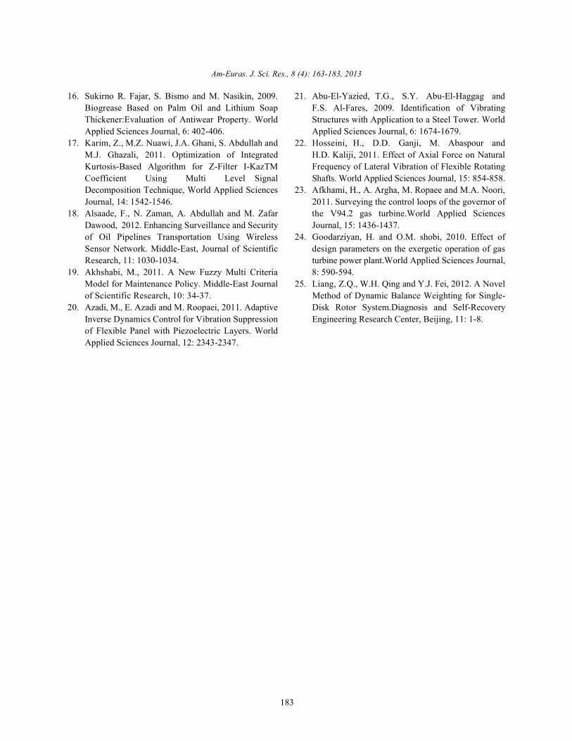
Rotor and Typical blades of gas turbine the related lubricants to journals. Evaluation of AntiwearSIEMENS162MW- V94.2 shown in Figure 11.and blades Property recently developed too much and the lubricationdesign features plot shown in Figure 12. condition of machine improve considerably and this cause
Also Employing Wet Compression System Available improving in machinery performance oil analysis also isin Market Since 2003. another powerful tools used in preventive maintenance
Now we have better understanding about machinery [16] the resolution of graphs in condition monitoringfeatures and options of gas turbine SIEMENS162MW- systems and also the filtering system of such data andV94.2and we can go through vibration concepts and our diagrams is one of the other challenging concepts inbalancing case histories more effectively [13] the coupling preventive maintenance of gas turbines. these kind of
one of the common fault in gas turbine and other most

Am-Euras. J. Sci. Res., 8 (4): 163-183, 2013
169
Fig. 7: Typical APT Software pages (rotor dimensions).
Fig. 8: SIEMENS V94.2 Gas Turbine Features
Am-Euras. J. Sci. Res., 8 (4): 163-183, 2013
170
Fig. 9: V94.2 Gas Turbine Combustion chamber features
Fig. 10: Some SI3D Blading Samples
Fig. 11: Typical blades of gas turbine SIEMENS162MW- V94.2

Am-Euras. J. Sci. Res., 8 (4): 163-183, 2013
171
Fig. 12: Blades design features plot
Fig. 13: Wet compression process
abilities improve too much in recent condition parts combine with new vibration analysis techniques andmonitoring systems the Signal Decomposition new process planning soft wares [19] detective of theTechniques and ability develop too much in recent years micro vibrations is one of the important capabilities in gas[17]. Wireless Sensor Network is one of the new patent turbine monitoring systems recently develop too muchand innovation in condition monitoring systems the most these capabilities help us to have better understanding inimportant advantages of these kind of facilities is that diagnosis of some critical faults like bent shaft, shaftthese kind of systems reduce the installation errors as well crack, rotor rub, wear, oil instability and so on.in theseas possible bside this different maintenance groups kind of techniques The piezoelectric layers are used ascan have continues and easy accesses to machine sensors and actuators. Micro-vibrations, generallyinformation that previously was not possible [18] new defined as low amplitude vibrations at frequencies up tomaintenance strategy and modeling systems developed 1 kHz, are now of critical importance in a number of areasin recent years reliability centered maintenance is a like preventive maintenance [20] the vibration structure ismaintenance technology recently develop and could also one the most important concept in vibration analysisreduce the maintenance cost considerably. this method of most critical equipment specially gas turbines thebase on stochastically information in all maintenance phase analysis is one of the most effective methods in
Am-Euras. J. Sci. Res., 8 (4): 163-183, 2013
172
this way. by triggering the TWF signals with base rotorvibration we can better understanding about differentbase vibration of machine in different points andpositions such data will help us a lot to recommendoptimal maintenance actions [21] axial vibrations consideras important factor in vibration analysis two parallel nonecontact probe measuring the axial vibration of rotor end inturbine and compressor these kind of probes should beequal to each other by 0.01 volt accuracy otherwise it mayrepresented abnormal motion of the shaft. alsomisalignment and coupling motion could easily evaluatedby these kind of techniques [22] the control loops of thegas turbine SIEMENS162MW- V94.2 consist of differentparts like temperature control, speed control, compressorout pressure grad control, limit load control for bothspeed and temperature and also fuel system. the accurateand close monitoring of each items will help us to improvethe quality of our vibration analysis. [23] the energybalance is one of the most important items in gas turbineutilities. several modeling techniques developed recently.Energy balance for each components and for the wholegas turbine system was considered in these kind oftechniques. the first and second thermodynamic laws helpus during these processes. compressor and turbine inletand outlet pressure and temperatures are importantfactors in these kind of activities. process parameterbalance will help us to improve mechanical and vibrationmachine behavior during operation.it means that isimportant for us to monitor the process condition and tryto keep all process condition like inlet and out let pressureand temperature in the range of technical document of gasturbine as well as possible [24].
RESULT AND DISCUSSION
In this part I will explain four case history all aboutSIEMENS V94.2 Gas Turbine utility in different vibrationalert condition in the main board operation recentlydeveloped. the first two was real alert signal andbalancing operation face quite challenging process andfinally was successful and cause changing the conditionof machine as well as possible and gas turbine couldcontinue operation after balancing the third case historywas about the condition that the alert signal in the mainboard was unreal and the system could continueoperation. the last case history show that sometime therecommended balance weights are out of technicaldocument ranges and it is not possible to reduce high
Table 1: Relative Vibration µm before balancingBefore Balancing-------------------------------------------------------------
Relative Vibration µm 980 RPM CE OCE COMP TURStart Up 17.4 16.5 67.8 77.9
Table 2. Absolute Vibration mm/s before balancingBefore Balancing
Absolute Vibration mm/s 980 RPM COMP TURStart Up 5.9 17.3
Table 3: Absolute turbine and compressor vibration after balancingFars utility (Unit 5) COM.(abs) TUR.(abs)1000 RPM Start up 2.3 8.4
Shut down 2 81400 RPM Start up 1.7 4
Shut down 2 6.33000 RPM (116 MW) 2.5 6.4
Table 4: Relative Vibration µm before balancingBefore Balancing-------------------------------------------------------------
Relative Vibration µm 1800 RPM CE OCE COMP TURStart up 64 152 71.4 35.3Shut down 51 159.3 72.3 51.4
overall vibration by adding balancing weights.Finally i hope the readers have better understanding ofthe vibration behavior of gas turbine in bently Nevadaalert condition.
case history number 1 :Fars utility-unit 5
duration:
From Tuesday, July 3, 2012 to Thursday, July 5, 2012
Due to the condition monitoring reports archive thevibration was over 17 mm/s in the startup time in 980 RPMthis vibration is over dander limitation set up 14.7 mm/stherefore the gas turbine tripped. and it cause that wecould not measuring any vibration data in operation RPMor in base load condition therefor balancing operation ismore complicated and faced serious challenging becauseit should be in operation condition the vibration of thegas turbine in the shut down or trip moment was asfollowing :
We analyzed the condition monitoring data in tripmoment and realized that the main vibration peak was 1Xtwo direction amplitude overall both considerably highand the phase data shows 90 degree shift between twomain direction in that moment all these evidence lead us

Am-Euras. J. Sci. Res., 8 (4): 163-183, 2013
173
Fig. 14: Trip vibration condition
Fig. 15: Vibration condition in first balancing stage
Fig. 16: Vibration condition in 3000 RPM

Am-Euras. J. Sci. Res., 8 (4): 163-183, 2013
174
Fig. 17: Vibration condition in 3000 RPM after synchronize the unit by process
Fig. 18: Startup vibration of generator journal Before balancing process
Fig. 19: Shut down vibration of generator journal Before balancing process

Am-Euras. J. Sci. Res., 8 (4): 163-183, 2013
175
Fig. 20: Startup vibration of turbine journal Before balancing process
Fig. 21: Shut down vibration of turbine journal Before balancing process
Fig. 22: Startup vibration of generator journal after balancing process

Am-Euras. J. Sci. Res., 8 (4): 163-183, 2013
176
Fig. 23: Shut down vibration of generator journal after balancing process
Fig. 24: Startup vibration of turbine journal after balancing process
Fig. 25: Shut down vibration of turbine journal after balancing process

Am-Euras. J. Sci. Res., 8 (4): 163-183, 2013
177
Table 5: Absolute Vibration mm/s before balancingBefore Balancing----------------------------------------------------
Absolute Vibration mm/s 1800 RPM COMP TURStart up 6.1 6.2Shut down 6.1 5.8
Table 6: Relative Vibration µm after balancingAfter Balancing------------------------------------------------------------
Relative Vibration µm 1800 RPM CE OCE COMP TURStart up 30.7 37.2 30.7 24.6Shut down 12 14 37.7 34.5
Table 7: Absolute Vibration mm/s after balancingAfter Balancing---------------------------------------------------
Absolute Vibration mm/s 1800 RPM COMP TURStart up 2.9 3.5Shut down 2.7 3.1
to unbalance problem we decided to operate balancing without any problem.program in two steps because gas turbine was on tripcondition and we could not operate the machine in case history number 3 : Shahrod utility-unit 2process RPM.in first step we planning to operate thebalancing process in 3000 RPM between the period of durationSaturday, May 12, 2012 and Tuesday, May 15, 2012 in thisstage we installed 19 balancing weights in Compressor from Tuesday, May 1, 2012 to Friday, May 4, 2012Disk Stage ten 165° and 27 balancing weight in turbineStage four 165° but unfortunately process have some Due to the process report about high relativeconsiderations and they could not running the gas vibration in different point of gas turbine specially in OCEturbine in the operation condition then we had to waiting journal approximately 134 micrometer peak to peak afterfor the suitable condition to operate the next stage of overhaul the session between different maintenancebalancing program. group in Tuesday, May 1, 2012 take placed. these
In the next stage process operate the gas turbine in vibrations caused the gas turbine shut downed the trends3000 RPM and balancing operation continue between the of process parameter was in the range of technicalperiod of Tuesday, July 3, 2012 and Friday, July 6, 2012, documents of both turbine and compressor also thefinally we decided to install 15 balancing weight in machinery bearing clearances was in the range of theCompressor Disk Stage ten 150 ° and 23 balancing weight document therefor the session result was make a vibrationin turbine stage four 155°. committee by both condition monitoring (CM), electrical
Absolute turbine and compressor vibration after special tools and balancing group together to makebalancing shown in following table : decision about the signals accuracy first of all CM records
In conclusion after synchronize the unit by process show that the frequency shift random but the overallin Monday, July 23, 2012 and analysis the vibration trends amplitude is relatively in same situation all over thein the base load we can operate the gas turbine in process startup and shut down process these kind of behaviorcondition with close monitoring. reject the hypothesis of probe looseness and also the 1X
case history number 2 :Kerman utility-unit 2 beside this the phase have not 90 degree shift between
duration: also rejected therefore they may have some problem in
from Wednesday, October 24, 2012 to Thursday, electronic considerations. the electrical special toolsOctober 25, 2012 group then planning the installation check in Wednesday,
The process of Kerman utility unit 2 reported that therelative vibration of OCE journal pass over 159micrometer peak to peak after the turbine passing 1800RPM(first critical speed) in shut down process afteranalyzing the vibration data we decided to operate thesingle panel balancing process on middle shaft atWednesday, October 24, 2012.
After adding trial weights finally we achieve to 19balancing weight 40 grams 155° the relative vibration of
OCE journal reduce too much when turbine passing1800 RPM [25] the vibration data before and afterbalancing shown in below tables.
The vibration trends before and after balancingoperation as following.
Due to the vibration overall amount after balancingprocessand vibration limits in technical document of thisgas turbine the vibration condition of this machine is ingood condition therefore this unit can continue operation
vibration was not always dominate in different RPM
two main direction therefore the unbalance hypothesis
adjusting probe installation or any related electrical or

Am-Euras. J. Sci. Res., 8 (4): 163-183, 2013
178
Fig. 26: Relative vibration trend startup turbine side before change the cables
Fig. 27: Relative vibration trend shut down turbine side before change the cables
Fig. 28: Relative vibration trend startup turbine side after change the cables

Am-Euras. J. Sci. Res., 8 (4): 163-183, 2013
179
Fig. 29: Relative vibration trend shut down turbine side after change the cables
Fig. 30: Vibration condition SIEMENS V94.2 Gas Turbine utility 3000 RPM without any load
May 2, 2012 they first check the distance between probes case history number 4 :Kerman utility-unit 4and the shaft by digital volt meter all the records wascorrect by 0.01 volt accuracy then they check the angle duration:that was 45 ° by 0.1 accuracy all was acceptable and in therange of technical document of gas turbine but there was from Wednesday, February 27, 2013 to Wednesday,a ridiculous mistake that the transfer cable must be 1 meter March 6, 2013.the installation guy install 1.5 meter cable that was therecommendedcable of gas turbine unit 6 by mistake and from Monday, March 11, 2013 to Sunday, March 17,the electrical resistance of these length of cable caused 2013.unreal signal and unreal signal cause unreal shut down ortrip the electrical special tools reinstall the probes with from Thursday, April 18, 2013 to Thursday, April 25,new cables and the gas turbine restart for operation the 2013.vibration trends in startup and shut down before and afterchange the cables is as following. Due to vibration trip unit four of Kerman utility on
Dou to the vibration overall amount after change the Monday, February 25, 2013 after overhaul in 940 RPMcables the vibration of this gas turbine is in good the field balancing team sent from Tehran to Kermancondition after overhaul and this gas turbine can continue the following operation accrue on unit four in first periodoperation and the trip vibrations was unreal or fake. (8 days). vibration analysis from this gas turbine

Am-Euras. J. Sci. Res., 8 (4): 163-183, 2013
180
Table 8: Turbine and Compressor vibrationsCompressor Turbine----------------------------------------- ----------------------------------------Abs (mm/s) Rel (µm) Abs (mm/s) Rel (µm)3 66 15 158
Table 9: Turbine and Compressor vibrations after first stage balancingprocess
Compressor Turbine----------------------------------------- ----------------------------------------Abs (mm/s) Rel (µm) Abs (mm/s) Rel (µm)2.7 32 15 162
Table 10: Turbine and Compressor vibrations after second stage balancingprocess
Compressor Turbine----------------------------------------- ----------------------------------------Abs (mm/s) Rel (µm) Abs (mm/s) Rel (µm)7.54 130 10.35 103
Table 11: Turbine and Compressor vibrations after third stage balancingprocess
Compressor Turbine----------------------------------------- ---------------------------------------- amount as following:Abs (mm/s) Rel (µm) Abs (mm/s) Rel (µm)5.4 97 8.12 80
Table 12: Initial Turbine and Compressor vibrationsCompressor Turbine----------------------------------------- ----------------------------------------Abs (mm/s) Rel (µm) Abs (mm/s) Rel (µm)5 100 8 85
Table 13: Turbine and Compressor vibrations Full speed-no loadCompressor Turbine----------------------------------------- ----------------------------------------Abs (mm/s) Rel (µm) Abs (mm/s) Rel (µm)4 73 6.2 76
Table 14: Turbine and Compressor vibrations Load= 40 MWCompressor Turbine----------------------------------------- ----------------------------------------Abs (mm/s) Rel (µm) Abs (mm/s) Rel (µm)4.58 105 6.28 85
Table 15: Turbine and Compressor vibrations Base loadCompressor Turbine----------------------------------------- ----------------------------------------Abs (mm/s) Rel (µm) Abs (mm/s) Rel (µm)4.5 121 7.12 92
Table 16: Turbine and Compressor vibrations Base load after one hourCompressor Turbine----------------------------------------- ----------------------------------------Abs (mm/s) Rel (µm) Abs (mm/s) Rel (µm)4.7 138 9.25 106
represented unbalance it means vibration FFT wasmainly in 1X, two main direction vibrations are bothhigh and have 90 degree shift in phase trend theseevidences represented high amount of unbalance thebalancing operation was not successful andrecommended high amount of balancing weightsthat was not possible according to the gas turbinetechnical document. we decided to checking themiddle shaft run out in several point thateverything was on machinery document ranges then werecommended LTE to operation the operation asked tofield balance the rotor as well as possible then thebalancing operation continued in previous RPM thevibration table was like below:
This time by adding the balancing weights like bellowthe gas turbine continue operation up to 1867 RPM andthen trip. five balancing weight added in 133° in FrontHollow Shaft and 14 balancing weight added in 125 ° inCompressor Disk Stage ten finally 9 balancing weightadded in 120° in Rear Hollow Shaft.the new vibration
In the next stage after adding the balancing weightslike below we could continue up to 3000 RPM. 9 balancingweight added in 35° in Front Hollow Shaft, 8 balancingweight added in 88° in Front Hollow Shaft,21 balancingweight in 45° in Compressor Disk Stage ten and 10balancing weight added in 205 ° in Rear Hollow Shaft theamount of new vibration recorded as following:
Finally by adding three weighting balance in RearHollow Shaft, 177° we achieved following vibrationbehavior in no load condition.
In these condition operation increasing the load upto 40 MW and the overall vibration increase up to 1 mm/s.
The exhaust liner was engage and the machinerymaintenance action take place In the next stage thealignment check operate by machinery group betweencompressor and generator due to the conditionmonitoring vibration analysis. In the next stage Wedecided to continue the balancing operation to reduce theamount of vibration on Thursday, April 18, 2013. the initialvibration amounts as following:
The balancing process continue by adding theweights, six weighting balance 240 gram added inintermediate Shaft 70 °,one weighting balance 180 gram inFront Hollow Shaft 5°,one weighting balance 115 gram inFront Hollow Shaft 60°, one weighing balance 180 gram inCompressor Disk Stage ten 75°, three weighting balance540 gram in Compressor Disk Stage ten 154°, threeweighting balance 475 gram in Compressor Disk Stage ten0° four balancing weight 720 gram in Rear Hollow Shaft

Am-Euras. J. Sci. Res., 8 (4): 163-183, 2013
181
Fig. 31: Full speed-no load Fig. 34: After 49 minute at Base load
Fig. 32: Base load balancing weight and restart the turbine the vibration
Fig. 33: After 45 minuteat Base load balancing weights or field balance.
240° and two weighting balance 295 gram in Rear HollowShaft 180°.the relative and absolute vibration change byloading the process condition as following:
After two hours the vibration over all turbine sidepass over 11.5 mm/s and gas turbine tripped and causeturbine shut down.the next stage in weight balancingprocess cause to reduce both journal bearings of turbineand compressor relative vibration but unfortunately theabsolute vibration of turbine side increased too muchfinally we had to remove all the weights (25 weightingbalance 1000 gram in intermediate Shaft 77°, threeweighting balance 540 gram in Front Hollow Shaft 355°,two weighting balance 360 gram Front Hollow Shaft 60°and seven weighting balance 1260 gram in Rear HollowShaft 274°). in the next stage by removing all above
behavior of gas turbine as following:As it is clear from the above vibration data vibration
in 3000 rpm and base load increasing graduallyrelated to no load condition this increasing is in bothabsolute and relative vibration also in both compressorand turbine side absolute vibration decreasing suddenlyin turbine side after 40 minute that turbine operate at baseload to 3 mm/s but about 4 minute later it has a sharpraise up to 5 mm/s then it increasing gradually and finallycause turbine trip due to the high initial overall vibrationof the gas turbine and also high amount of weightsrequested in balancing process and the documentrecommended limitation about balancing weights, this isthe optimal condition of the balancing process and thenext step will request out of rang weights therefore it isnot possible to reduce high overall vibration by adding

Am-Euras. J. Sci. Res., 8 (4): 163-183, 2013
182
Current & Future Developments: The vibration that jamshidi for their guidance and encouragement whichcan represented unbalance in most critical equipment were instrumental in the successful completion of thislike gas turbine utilities or steam turbine multistage paper.compressors should have three main characteristicfirst both two main direction vibration should high REFERENCEthen the phase trend in recent days should have 90degree shift between two main direction beside this 1. vibration school website: http://the FFT should have completely or more than 90 www.vibrationschool.com/, 2013.percent in 1X if any of these three condition was not 2. Kalmegh, A. and S. Bhaskar, 2012. Dynamicsatisfy you should not suspicious about unbalance Balancing of Centrifugal Pump Impeller. Internationalthe balancing process also sometimes face many Journal of Emerging Technology and Advancedchallenges in field balance process or balancing Engineering, 6: 221-223.operation in balance shop. the knowledge of the balance 3. Xie, D., 2012. rigid rotor balancing. wuhan universityengineers about technical machinery and technical publication, 3: 331-337.document of machine will help us to reduce the balancing 4. high speed rotor balance facilities, Elliott High Speedprocess time furthermore the fluctuation of overall Rotor Balancewebsite http:// www.elliottturbo.com/vibration may represented probe looseness or any High_Speed_Balance.asp, 2012.process problem in gas turbine or turbine compressor.the 5. Toshiba, 2013. Milwaukee Service Center, 6623CM engineer should have knowledge of process W Washington Street, West Allis, WI,condition of machine specially inlet and out let pressure 53214(414): 475-2800.and temperature trend of both turbine and compressor 6. Intelligent Balancing Solutions, hofmann productand also the quality of steam in steam turbines that is why website, www.hofmann-global.com, 2013.vibration analysts should have good cooperation with 7. World’s Leading Supplier of Soft-Bearing Balancingprocess and other maintenance groups and also have Machines & Instruments, IRD Balancing website,relative good technical knowledge of other maintenance www.irdbalancing.com, 2013.parts or operation the random fluctuation in frequency of 8. Mobile field balancing reduces vibrations in energyFFT may represented any probe maladjustment or and power plants, Dr. Edwin Becker, Prüftechnikincorrect probe installation or any possible mistake in Condition Monitoring, Published in VGB PowerTechrelated electrical or electronic areas cause unreal alert – 07/2012.signal or unreal trip. In the gas turbines the absolute 9. Kumar, S., R. Sehgal, R. Kumar and S. Bhandari, 2012.vibration will help us to distinguish these kind of unreal Vibrations Analysis of 4 Jaw Flexible Couplingsignals more easily by comparing absolute and relative Considering Unbalancing in Two Planes.vibration trends with each other all in all these kind of International Journal of Science and Technology,decisions should take with more consideration about all 11: 324-326.related aspect of the process like machinery, condition 10. Donth, D., A. Grunwald, C. Heilmann andmonitoring systems CM, balancing group history data, M. Melsheimer, 2012. Multi plane on site balancingprocess trends, non-contact probe installation or any of wind turbine drive trains, BerlinWind GmbH,related maintenance group history data these groups EWEA.should have good cooperation with each other to make 11. Brüel and Kjær website : http://www.bksv.com/, 2013the optimum decision in minimum time. 12. VMI website: http://www.vmiab.com/, 2013.
Conflict of Interest: The author does not have any Papers, 2012 http://www.energy.siemens.comconflict of interest to report. 14. Hariharan, V. and P.S.S. Srinivasan, 2010. Vibrational
ACKNOWLEDGEMENTS Unbalance. World Applied Sciences Journal,
It is with great pleasure and deep sense of gratitude, 15. Eftekhari, M., M. Javadi and R.E. Farsani, 2011.that I acknowledge the successful completion of this Free vibration analysis of cracked functionallypaper. My profound thanks and deep sense of gratitude graded material beam.World Applied Sciencesto my dear sister Elahe Ali zargarand my dear friend Ali Journal, 12: 1216-1222.
13. siemens website, Siemens Gas Turbines, Technical
Analysis of Flexible Coupling by Considering
8: 1024-1030.
Am-Euras. J. Sci. Res., 8 (4): 163-183, 2013
183
16. Sukirno R. Fajar, S. Bismo and M. Nasikin, 2009. 21. Abu-El-Yazied, T.G., S.Y. Abu-El-Haggag andBiogrease Based on Palm Oil and Lithium Soap F.S. Al-Fares, 2009. Identification of VibratingThickener:Evaluation of Antiwear Property. World Structures with Application to a Steel Tower. WorldApplied Sciences Journal, 6: 402-406. Applied Sciences Journal, 6: 1674-1679.
17. Karim, Z., M.Z. Nuawi, J.A. Ghani, S. Abdullah and 22. Hosseini, H., D.D. Ganji, M. Abaspour andM.J. Ghazali, 2011. Optimization of Integrated H.D. Kaliji, 2011. Effect of Axial Force on NaturalKurtosis-Based Algorithm for Z-Filter I-KazTM Frequency of Lateral Vibration of Flexible RotatingCoefficient Using Multi Level Signal Shafts. World Applied Sciences Journal, 15: 854-858.Decomposition Technique, World Applied Sciences 23. Afkhami, H., A. Argha, M. Ropaee and M.A. Noori,Journal, 14: 1542-1546. 2011. Surveying the control loops of the governor of
18. Alsaade, F., N. Zaman, A. Abdullah and M. Zafar the V94.2 gas turbine.World Applied SciencesDawood, 2012. Enhancing Surveillance and Security Journal, 15: 1436-1437.of Oil Pipelines Transportation Using Wireless 24. Goodarziyan, H. and O.M. shobi, 2010. Effect ofSensor Network. Middle-East, Journal of Scientific design parameters on the exergetic operation of gasResearch, 11: 1030-1034. turbine power plant.World Applied Sciences Journal,
19. Akhshabi, M., 2011. A New Fuzzy Multi Criteria 8: 590-594.Model for Maintenance Policy. Middle-East Journal 25. Liang, Z.Q., W.H. Qing and Y.J. Fei, 2012. A Novelof Scientific Research, 10: 34-37. Method of Dynamic Balance Weighting for Single-
20. Azadi, M., E. Azadi and M. Roopaei, 2011. Adaptive Disk Rotor System.Diagnosis and Self-RecoveryInverse Dynamics Control for Vibration Suppression Engineering Research Center, Beijing, 11: 1-8.of Flexible Panel with Piezoelectric Layers. WorldApplied Sciences Journal, 12: 2343-2347.