via r. sevardi, 8 - 42010 reggio emilia - italy radio-tv ... r. sevardi, 7 - 42010 reggio emilia -...
TRANSCRIPT

Analogue and Digital Radio-TV Transmittersóóóóóó General Catalogue 2007
Cte International srl Via R. Sevardi, 7 - 42010 Reggio Emilia - ItalyTel. +39 0522 509411 Fax +39 0522 509538e-mail [email protected] Web site www.cte.it Research & Development centre Via R. Sevardi, 8 - 42010 Reggio Emilia - Italy
Branch office in Rome Via Zoe Fontana, 220 - 00131 Roma - Italy
Ana
logu
e an
d D
igit
al F
M-T
V Tr
ansm
itte
rs
óó
óó
óó
Gen
eral
Cat
alog
ue 2
00
7Co
d. 6
0382
1 - P
rinte
d Ap
ril 2
007


�
S u m m a r y
CTE International 2-4
Our products
óó Section � 6-29 FMBroadcastingEquipment Digital&AnalogFMTransmitter&FMAmplifierswithoutputpowerupto10KW, DABExciter,AudioProcessor,RDSCoder.
óóSection 2 30- 45 TVBroadcastingDrivers DVB-T/HandAnalogUHFandVHFTelevisionDriveroutputpowerupto250W, Transposer,RegenerativeTransposer,Gap-filler,Digitalrepeater,MIPInserter.
óóSection 3 46-53 TVPowerAmplifiers UHFandVHFSolidStateAmplifierswithoutputpowerupto20KW
óóSection 4 54-63 Microwave&UHFLinks TVMicrowavelinks(from2,3GHzto23GHz)inDigitalandAnalogversion. RadioMicrowave(from1,4GHzto2,7GHz)&UHFlinks(from180MHzto450Mhz) FMProfessionalReceiver
óóSection 5 64-73 CompleteTVtransmittersandSystems AutomaticChangeOverSystem,CompleteTransmitters,UPS
óóSection 6 74- 89 Antennas&Combiners FMCavityFiltersandStarpointorDouble-BridgeCombiners WidevarietyofFMAntennasandUHForVHFBandPanelAntennaSystems.

2
Cte International was founded in 1972 withthe purpose of manufacturing and distributingtelecommunicationequipment.
The first range of products manufactured by CteInternational included transceivers and accessories(HF-VHF-UHFRadioEquipment)forprofessionalPMR-LMRandHam.CB,brandedMidlandandAlan.
C t e I n t e r n a t i o n a l
nero 40
pantone 877 The excellent quality of the products and thecompetitive prices allow Cte Internationalsuccessfullydistribute inthemajorCountriesof theEuropeanUnionandworldwide,thusconfirmingthecosmopolitanvocationofthecompany.
In 1975 Cte Broadcast began the production of FMRadioBroadcastingTransmitters.CteBroadcast,togetherwithitspartnerMetaSystemhasalwaysinvestedconsiderableresourcesinresearchanddevelopment.
Tomantainitsleadingposition,CteconstatlydevotesinvestmentstoR/D.Recent importantachievementshavebeenreachedbyourengineersinthenewDABandDVBtechnologiesforDigitalTransmission.

3
The Corporate Headquarters of the company are inReggioEmilia(Italy).TheproductionplantsarebasedinReggioEmiliaandinMilan.The company employs more than 350 people, 75 ofwhom are technicians and engineers granting thehigh quality and reliability of the CTE Internationalproducts.
ThefacilitiesinReggioEmiliaandMilaninclude:› More than8.000squaremetersofmanufacturingandsupportfacilities.
› Ultra-moderninstrumentationforTesting,ResearchandDevelopment.
› Automatic and modern machinery for worldwideshipping.
› Climaticchamberandvibrationplatform.› Graphicthermalcontrolequipment› AnechoicchamberforimmunityemissionEMCtestupto18GHz
Theproductionincludes:› SolidstateanalogterrestrialFMTRANSMITTERS,upto20KW
› Solid state analog terrestrial TELEVISIONTRANSMITTERS operating both in VHF and UHFbands,upto20KW
› DABDIGITALAUDIOTRANSMITTERSinLbandandIIIbandupto5KW
› DVBDIGITALVIDEOTRANSMITTERSinUHFbandupto5KW
› ANTENNASYSTEMS,FILTERS,DIPLEXERS.› CUSTOMIZEDSOLUTIONS
Customized solutions to meet anyparticularrequirementsofthemarket.
Cte International operates a qualitymanagement system in compliance withtherequirementsofUNIENISO9001:1994
C o r p o r at e H e a d q u a r t e r s

4
ALANCOMMUNICATIONJSCSamokatnayaStr.1-Building12Moscow111116-RussiaTel. +70959180352Fax +70959180832web-site:www.midland.ru
ALANTELEKOMUNIKACJASp.zo.o.Jawczyce,ul.Poznanska6405-850OïarówMaz.,PolandTel. +227223500Fax +227222995E-mail:[email protected]
ALANTELECOMMUNICATIONLtdNo.185,SlivnitzaBlvd.1233Sofia-BulgariaTel. +35929312101Fax +35929311534web-site:www.alanbulgaria.com
ALANUKltdUnit2,Callenders-PaddingtonDriveSwindonSN57YW-EnglandTel. +441793882431Fax +441793882432E-mail:[email protected]:www.alan-uk.com
ALANHELLASltd25thMartiou13,Tavros17778Athens-GreeceTel.+302104829634Fax+302104829635e-mail:[email protected]:www.alan.gr
SisterCompaniesandJointVentures
CTEDIgITALBrOADCASTs.r.l.-ELITViaGadames,9320151Milano(Italy)Tel. +39023021101/2/3Fax +39023084468e-mail:[email protected]:www.cte-elit.it
CTEDIgITALBrOADCASTINgMalaysiaSdnBhdSuite15.03,Level15,MenaraHawPar,JalanSultanIsmail,50250KualaLampur-MalaysiaTel. +60320317800Fax +60320315800e-mail:[email protected]:www.cte.it
CTEDIgITALINDONESIA2ndFloor,JalanDarmawangsaVI.No.3512160KebayoranBaru-Jakarta-IndonesiaTel.+622172788480Fax +622172788759e-mail:[email protected]
ALANTELECOMPTELTD111NorthbridgeRoad08-28PeninsulaPlazaSingapore179098Tel. +6568830618Fax +6568830748e-mail:[email protected]
ALANELECTrONICSgMBHDaimlerstraße1KD-63303Dreieich-GermanyTel. +496103/9481-0Fax +496103/9481-60web-site:www.alan-germany.com
Headquarters
CTEINTErNATIONALs.r.l.ViaR.Sevardi742010zonaInd.Mancasale-ReggioEmilia-ItalyTel. +390522509450Fax. +390522509448e-mail:[email protected]:www.cte.it
C t e B r o a d c a s t i n t h e W o r l d
BranchofficeinromeViaZ.Fontana220-Tecnocittà00131Roma-ItalyTel.+390641299022Fax+390641234855

AnalogueandDigital radio-TVTransmitters
Sincethiscataloguehasarelativelylongvaliditypleaseaskforconfirmationofalldataatthetimeoforderingorwhenconsideringapurchase.
óóóóóóOurproducts

6
LowPowerFMTransmittersTX 25 PLUS – 25 WTX 250 PLUS – 250 W
FMBroadcastingEquipment
TheTX25PLUSandTX250PLUSFMExcitersaredesignedtoacceptStereoMonoMPXAudioSignalstobemodulatedinFMandtoamplifytheRF.TheTX25PLUSandTX250PLUSFMareequippedwithaninnovativeandhigh-performancepowersupplystage«switching-modemainsdirect»,withoutmainstransformer(themainsvoltagecanvaryfrom80to265Vacwithnovariationontheoutputpower).Themajorfeaturesincludehighinsulationfrommains,highoverallefficiency,modulardesignfor
friendlymaintenance,compliancewithEuropeannormsEN61000-4-3andlongtermreliability.IntheseFMExciters,anAGCaudiocircuitcontrolisincludedtokeepthemodulationlevelbelowthemaximumfiguresallowedincompliancewithCEPT/ERC5401E.TheRFoutputspecificationshavebeendrasticallyimproved,thusobtainingfigureswhicharecomparabletodigitaltransmitters.TheseFMExciterscanbecontrolledlocallybyaPCorremotelybymodem.
TheTX25PLUSisacompletelysolidstateExciter,frequencyagilecontrollablefromthefrontpanelwithadjustableoutputpowerupto25W.Thepowerdeviceusedtoobtain25WisthePHILIPSBLF245.InTX250PLUSFMExciter,usablealsoasastand-alonetransmitter,wehaveaddedapoweramplifiermodulewiththepowerdevicePHILIPS278,abletogrant250Woutputpowerintheentirefrequencyrange.
Code Model Description
F662 TX 25/S PLUS 25WStereo,MonoMPXTransmitter
F663 TX 250/S PLUS 250WStereo,MonoMPXTransmitter

7FMBroadcastingEquipment
TechnicaldataFrEQUENCYRange 87,5÷108MHzInternalSettingmode 10KHzstepsExternalSettingmode 10KHzstepsbyremotecontrolRS232-RS485Generation PLLsynthesizerControl MicroprocessorOutputfrequencystability ±300Hz/3monthsReference TCXO12,8MHzNominaldeviation ±75KHzStabilityofFrequencyDeviation ±2,5%over6monthsImpedanceRFConnector 50OhmrFOUTPUTSPECIFICATIONSHarmonicssuppression <-75dBcSpuriousEmission <-90dBcOffLockAttenuation >60dBcS/NRATIO(weighted) >73dB(referredto±75KHz)THD 0,10%VSWR Lessthen1,5:1Probe BNCconnectorRF–40dB
BNCconnectorLFMONOMPXSPECIFICATIONSMono/MPXImpedance 600Ohmbal.or10KOhmunbal.,
XLRfemaleConnectorMonoLevel From-6to+12dBmMPXLevel -6dBmAudioFilterResponse >30dB(from19KHzto100KHz)THD <0,2%From40Hzto15KHzSuppressionof19KHz >46dBRDSandSCAImpedance 10KOhmunbal.,BNCConnector(with30Hz
to100KHzFilter)
STErEOSPECIFICATIONSLeft,andRightImpedance 600Ohmbal.or10KOhmunbal,
XLRfemaleConnectorLeft,RightLevel From–6to+12dBmCrosstalk >50dB(@19KHz)THDonEncodedchannels <0,3%From0,4Hzto15KHzSuppressionof38KHz >50dBSpurioussuppressionoutsideband
AccordingtoETSI300-384
SubCarrierGeneration InternalCristalPilotFrequency 19KHz±1HzDESIgNDATAType SolidstatedirectFMfrequencyPre–emphasis Flator75or50μsAudiofrequencyresponse ±0,2dB(from40Hzto15KHz)(stereo)
±0,3dB(from40Hzto100KHz)(MPX)Unbalancerejection >40dBModulation Type:DirectVCOfrequencymodulationF3E/F8E
Capability:MeetsorexceedsallCE99/05R&TTErequirements
rEMOTECONTrOLOutputConnector RS232–PCconnection(frontpanel)
RS232Amplifierconnection(rearpanel)RS485(rearpanel)
InputConnector RS485(rearpanel)STANDArDSCOMPLIANCERadiospectrum ETSI300-384;ETS302-018EMC ETSI300-447;ETS301-489Safety EN60950-EN60215TEMPErATUrEOperatingrange 0°to45°CStoragerange -40°to60°CMaximumrelativeHumidity 90%noncondensingMaxOperatingAltitude 2500mt.a.s.l.
SPECIFICaTIOnS TX 25 PLUS TX 250 PLUSrFoutputpower From0to25W From5to250WOutputConnector NTypeFemale NTypeFemaleDimensions(WxHXD)mm 482x88x500(550x220x60Package) 482x88x500(550x220x60Pack)Weight 10Kg(12.6Kg.Package) 12Kg(15.5Kg.Package)Powerconsumption Approx.<75VA Approx.<350VANumberofpowersupplies 1From80to265Vac,singlephase; 1From80to265Vac,singlephase;DCPowerSupply Notincluded NotincludedNumberoffans 1blower220Vac 2blowers220Vac

8
MediumPowerFMTransmittersTX 1 – 1000 WTX 05 – 500 W
FMBroadcastingEquipment
TheTX1andTX05arereallyinnovativeFMTransmitterswith1000Wand500Woutputpowerrespectively.Thankstothenewsolutionsthatourengineershaveimplementedinthecircuitryandtothecompactdesign,forthesetransmitterswehaveestimateda20%longerMTBFwithrespecttotheaveragesimilarmodelsavailableinthemarket.
TheTX1andTX05areequippedwithamicroprocessorboardthatallowstheprogrammingfromthelocaldisplayorevenremotely,throughastandardRS232orSNMP.Thankstotheultimateelectroniccomponentsthathavebeenlargelyimplementedinthedesign,alsotheRFspectrumspecificationshavebeensignificantlyimproved
TheequipmentcomplieswiththeRTTEEuropeanRequirements.-SolidstateamplifierwithMosfettechnology.-OutputPoweradjustablefrom100Wto1000W-Userfriendlyformonitoringandcontrol-Doublestagepowersupply-Fastandmultipleprotections-Compactandmodulardesignforquickandeasymaintenance-Flexibletelemetrysystemandremotecontrol-N+1Hardwareandsoftwarecontrolfacility
Code Model Description
F866 TX � 1000WStereo,MonoMPXTransmitter
F872 TX 05 500WStereo,MonoMPXTransmitter

9FMBroadcastingEquipment
TechnicaldataFrEQUENCYRange 87,5÷108MHzInternalSettingmode 10KHzstepsExternalSettingmode 10KHzstepsbyremotecontrolRS232-RS485Generation PLLsynthesizerControl MicroprocessorOutputfrequencystability ±300Hx/3monthsReference TCXO12,8MHzNominaldeviation ±75KHzStabilityofFrequencyDeviation ±2,5%over6monthsImpedanceRFConnector 50OhmrFOUTPUTSPECIFICATIONSHarmonicssuppression <-75dBcSpuriousEmission <-90dBcOffLockAttenuation >60dBcS/NRATIO(weighted) >73dB(referredto±75KHz)THD 0,10%VSWR Lessthen1,5:1Probe BNCconnectorRF–40dB
BNCconnectorLFMONOMPXSPECIFICATIONSMono/MPXImpedance 600Ohmbal.or10KOhmunbal.,
XLRfemaleConnectorMonoLevel From-6to+12dBmMPXLevel -6dBmAudioFilterResponse >30dB(from19KHzto100KHz)THD <0,2%From40Hzto15KHzSuppressionof19KHz >46dBRDSandSCAImpedance 10KOhmunbal.,BNCConnector(with30Hz
to100KHzFilter)
STErEOSPECIFICATIONSLeft,andRightImpedance 600Ohmbal.or10KOhmunbal,
XLRfemaleConnectorLeft,RightLevel From–6to+12dBmCrosstalk >50dB(@19KHz)THDonEncodedchannels <0,3%From0,4Hzto15KHzSuppressionof38KHz >50dBSpurioussuppressionoutsideband
AccordingtoETSI300-384
SubCarrierGeneration InternalCristalPilotFrequency 19KHz±1HzDESIgNDATAType SolidstatedirectFMfrequencyPre–emphasis Flator75or50μsAudiofrequencyresponse ±0,2dB(from40Hzto15KHz)(stereo)
±0,3dB(from40Hzto100KHz)(MPX)Unbalancerejection >40dBModulation Type:DirectVCOfrequencymodulationF3E/F8E
Capability:MeetsorexceedsallCE99/05R&TTErequirements
rEMOTECONTrOLOutputConnector RS232–PCconnection(frontpanel)
RS232Amplifierconnection(rearpanel)RS485(rearpanel)
InputConnector RS485(rearpanel)STANDArDSCOMPLIANCERadiospectrum ETSI300-384;ETS302-018EMC ETSI447;ETS301-489Safety EN60950-EN60215TEMPErATUrEOperatingrange 0°to45°CStoragerange -40°to60°CMaximumrelativeHumidity 90%noncondensingMaxOperatingAltitude 2500mt.a.s.l.
SPECIFICaTIOnS TX 0� TX 05rFoutputpower From100to1000W From50to500WOutputConnector 7/16TypeFemale 7/16TypeFemaleDimension(WxHXD)mm 482x132x700(550x270x800Package) 482x132x700(550x220x800Package)Weight 18Kg(20Kg.Package) 17Kg(19Kg.Package)Powerconsumption Approx.<1800VA Approx.<900VANumberofpowersupplies 230Vac±15%,singlephase; 230Vac±15%,singlephase;Numberoffans 2blowers24Vdc 2blowers24Vdc

�0
remotecontrol system
ThisremotecontrolsystemforFMtransmitterscanbeoperatedbyCableorbyGSMModem;basically,
itallowsmonitoringandmodifyingremotelythe
overallsettingoftransmitters.Incaseoffailuresinthetransmitterwhichisundercontrol,thesoftwareoftheremotecontrolautomaticallysendsanSMSwarningmessage.
DESCrIPTIONAllthemainparameters(frequency,levels,mono-stereo-pre-emphasis,outputpower)areadjustablethroughthekeypadandareautomaticallystoredinthememory,evenincaseoflackofmains.Manyeventscanbestored;everyalarminformationisadvisedwithitsstartalarmdateandtheendalarmdate.Themainmeasurementsrealizedbythissystemare:valueofmodulation,heatsinktemperature,mainslinevoltage,voltageandcurrentoftheRFfinalstage,mainoscillatorfaulty.Thetransmittercanbecontrolledbymeansofthekeypadorinremotemode.Asamonitor,acommonpersonalcomputercanbeconnectedonthededicatedconnectoronthefrontpanel.BysimplyinstallinganappropriateprogramonthePC,itispossibletosetandseealltheparameters.EverytransmittercanbeconnectedtoaGSMModemwithanexternalantenna,tolinkthetransmittertothepublictelephonenetwork.Itispossibletocontrolandmodifyalltheparametersofthetransmitterjustlikeiftheuserwereonthesite.
Code Model Description
F634.06 Modemanalogico
F634.07 ModemGSM
F634.08 Opzionesoftware
FMBroadcastingEquipment

��FMBroadcastingEquipment
TECHNICALFEATUrES›Remotesettingandmeasurementof:directpower,reflectedpower,modulation,current,voltage,temperature,powersupply›ImmediateinformationviaGSMonunexpectedevents(managedbytwodifferenttelephonenumbers)›Passwordassystemprotection›Friendlyuse›OperatedbyTCP/IPprotocolusingSNMPprotocol
PCSystemrequirements:ProcessorType:PENTIUMorhigherOperativesystem:WINXPRAM:256MBGraphic:SVGA600x800/768x1024
SOFTWArE
EXAMPLEOFASTANDArDTrANSMITTINgSTATION
Site1-TX25PLUSTransmitterwithModemGSM
PCRemoteStation(controlalltheparameter)
Site2-TX1TransmitterwithModemGSM
Site3-VL3TransmitterwithModemGSM

�2
Compact FMPowerAmplif iersVL 1 – 1000 WVL 05 – 500 W
FMBroadcastingEquipment
TheVL1andVL05arereallyinnovativeFMAmplifierswith1000Wand500Woutputpowerrespectively.Thankstothenewsolutionsthatourengineershaveimplementedinthecircuitryandtothecompactdesign,fortheseamplifierswehaveestimateda20%longerMTBFwithrespecttotheaveragesimilarmodelsavailableinthemarket.
TheVL1andVL05areequippedwithamicroprocessorboardthatallowstheprogrammingfromthelocaldisplayorevenremotely,throughastandardRS232orSNMP.Thankstotheultimateelectroniccomponentsthathavebeenlargelyimplementedinthedesign,alsotheRFspectrumspecificationshavebeensignificantlyimproved.
TheequipmentcomplieswiththeRTTEEuropeanRequirements.-SolidstateamplifierwithMosfettechnology.-OutputPoweradjustablefrom100Wto1000W-Userfriendlyformonitoringandcontrol-Doublestagepowersupply-Fastandmultipleprotections-Compactandmodulardesignforquickandeasymaintenance-Flexibletelemetrysystemandremotecontrol-N+1hardwareandsoftwarecontrolfacility
Code Model Description
F868 VL � 1000WPowerAmplifier87.5-108MHz
F867 VL 05 500WPowerAmplifier87.5-108MHz

�3FMBroadcastingEquipment
TechnicaldatarFOUTPUTSPECIFICATIONSRange 87,5÷108MHzOverallefficiency Betterthan58%ImpedanceRFConnector 50OhminputandoutputOutputpowerstability ±3%Harmonicssuppression ≥-80dBc(typicallybetterthan90dBc)SpuriousEmission <1μW(withoutModulation)ResidualAsynchronyAM -74dBWeighedResidualSynchronyAM -58dBWeighedProbe BNCconnectorRF–60dBcPOWErSUPPLYType Switchmode(Doubleconversionvoltagedirect
mains)Protections Overheating70°C(bymeansoftheGeneral
Controlstage)OverchargeShortCircuitontheoutputvoltageCrow–Barprotection:(Excessiveoutputvoltagelimit)ExcessivecurrentconsumptionoftheRFmoduleOver-voltage
DESIgNDATADisplayMeter Forwardpower-Reflectedpower-DCsupply
voltage-DCsupplycurrent-Powersupplytemperature-Poweramplifiervoltage
Protections RFAmplifiermoduleover-temperature70ExcessivereflectedpowerPermissibleVSWR≤1.5
Programmablelogicprotection Stoppingoftheunitafter8alarmsStoppingoftheunitafter16alarms
Logicprotectionsreset Manual,RemoteorAutomaticallyevery24hours
Controls Mains-DB15Connector(Stand-byandResetcommand)
Alarm ExcessiveoutputSWR(redled)50Wadj.–Alarm(redled)-Stand–by(yellowled)-Mains-DCout–ALC
Type SolidstatedirectFMfrequency
rEMOTECONTrOLOutputConnector RS232interfaceConnectorDB9Male–Two
ConnectorDB9Femaleprogrammable–RS485-ConnectorDB15Male
OutputConnectorAnalogue SignalproportionaltotheoutputvoltageofthepowersupplymoduleSignalproportionaltothecurrentsuppliedbythepowersupplymoduleSignalproportionaltothesquarerootofthedirectpowerSignalproportionaltothesquarerootofthereflectedpower
OutputConnectorDigital “Stand-by”signal(contactisN.C.innormaloperations,connectedtoGNDinstand-bymode)“N.O.”alarmcontact(contactisnotconnectedinnormaloperation,connectedtopin15inalarm)“N.C.”alarmcontact(connectedtopin15inalarm,contactisnotconnectedinnormaloperation)
InputConnector Stand-bycommandResetcommand
Ethernetinterface(option) ConnectorRJ46WEBbrowserorSNMPclientSTANDArDSCOMPLIANCERadiospectrum ETSI302-018EMC ETSI301-489Safety EN60950-EN60215TEMPErATUrEOperatingrange 0°to45°CStoragerange -40°to70°CMaximumrelativeHumidity 90%@26°CnoncondensingMaxOperatingAltitude 2500mt.a.s.l.
SPECIFICATIONS VL 05 VL �rFoutputpower From50to500W From100to1000WOutputConnector 7/16TypeFemale 7/16TypeFemaleDimensions(WxHXD)mm 482x132x700(550x220x800Package) 482x132x700(550x270x800Package)Weight 17Kg(19Kg.Package) 18Kg(20Kg.Package)Powerconsumption Approx.<900VA Approx.<1800VANumberofpowersupplies 230Vac±15%,singlephase; 230Vac±15%,singlephase;Numberoffans 2blowers24Vdc 2blowers24Vdc

�4
FMPowerAmplif ierVL 3 – 2500 W
FMBroadcastingEquipment
Thisinnovativeandcompactamplifierisabletosatisfythestrictestrequestsofallend-userswhoarelookingforhighreliableandtop-qualityequipmentatcompetitiveprices.Allthedeclaredoperationalparametersareassuredintheentirefrequencyrangeandforextremeenvironmentalconditions.
Thankstotheadvancedapproachinthedesignfocusedonlowpowerconsumptionandlinearityovertheentireoperativeband,weestimatea20%longerMTBFwithrespecttotheaveragestandardequipmentavailableinthemarket.
TheequipmentcomplieswiththeRTTEEuropeanRequirements.-Mosfettechnology-Userfriendlyformonitoringandcontrol-Doublestagepowersupply-Fastandmultipleprotections-Modulardesignforquickandeasymaintenance-Flexibletelemetrysystemandremotecontrol-N+1Hardwareandsoftwarecontrolfacility
Code Model Description
F869 VL 3 2500WPowerAmplifier87.5-108MHz

�5FMBroadcastingEquipment
TechnicaldatarFOUTPUTSPECIFICATIONSRange 87,5÷108MHzOverallefficiency Betterthan58%ImpedanceRFConnector 50OhminputandoutputOutputpowerstability ±3%Harmonicssuppression ≥-80dBc(typicallybetterthan90dBc)SpuriousEmission <1μW(withoutModulation)ResidualAsynchronyAM -74dBWeighedResidualSynchronyAM -58dBWeighedProbe BNCconnectorRF–60dBcPOWErSUPPLYType Switchmode(Doubleconversionvoltagedirect
mains)Protections RFAmplifiermoduleover-temperature70
ExcessivereflectedpowerPermissibleVSWR≤1.5
Programmablelogicprotection Stoppingoftheunitafter8alarmsStoppingoftheunitafter16alarms
Logicprotectionsreset Manual,RemoteorAutomaticallyevery24hours
Controls Mains-DB15Connector(Stand-byandResetcommand)
Alarm ExcessiveoutputSWR(redled)50Wadj.–Alarm(redled)-Stand–by(yellowled)-Mains-DCout–ALC
Type SolidstatedirectFMfrequency
rEMOTECONTrOLOutputConnector RS232interfaceConnectorDB9Male–Two
ConnectorDB9Femaleprogrammable–RS485-ConnectorDB15Male
OutputConnectorAnalogue SignalproportionaltotheoutputvoltageofthepowersupplymoduleSignalproportionaltothecurrentsuppliedbythepowersupplymoduleSignalproportionaltothesquarerootofthedirectpowerSignalproportionaltothesquarerootofthereflectedpower
OutputConnectorDigital “Stand-by”signal(contactisN.C.innormaloperations,connectedtoGNDinstand-bymode)“N.O.”alarmcontact(contactisnotconnectedinnormaloperation,connectedtopin15inalarm)“N.C.”alarmcontact(connectedtopin15inalarm,contactisnotconnectedinnormaloperation)
InputConnector Stand-bycommandResetcommand
Ethernetinterface(option) ConnectorRJ46WEBbrowserorSNMPclientSTANDArDSCOMPLIANCERadiospectrum ETSI302-018EMC ETSI301-489Safety EN60950-EN60215TEMPErATUrEOperatingrange 0°to45°CStoragerange -40°to70°CMaximumrelativeHumidity 90%@26°CnoncondensingMaxOperatingAltitude 2500mt.a.s.l.
SPECIFICATIONS VL3rFoutputpower 2500WNr.ofTransistors 8MOS-FETSD2942rFInput(NominalLevel) 40WOutputConnector 7/8EIADimensions(WxHXD)mm (482x220x700)+(482x88x700)Weight 30+14KgPowerconsumption Approx.<4800VAPowersupplyreq. three-phase380Vac±15%/230Vacmono-phaseNr.ofpowersupplyboards 3Numberoffans 2blowersforeachPA&PSmodule

�6
FMPowerAmplif iersVL 5 – 5 KWVL 10 – 10 KWVL 20 – 20 KW
FMBroadcastingEquipment
Thisinnovativeandcompactamplifierisabletosatisfythestrictest requestsofallend-userswhoare lookingforhighreliableandtop-qualityequipmentatcompetitiveprices.All thedeclaredoperationalparametersareassured in theentire frequency range and for extreme environmentalconditions.Bymeansof theadvancedapproach in thedesign focusedon low power consumption and linearity over the entireoperativeband,weestimatea20%longerMTBFwithrespecttotheaveragestandardequipmentavailableinthemarket.The equipment complies with the EN 302-018 EuropeanRequirement.-Mosfettechnology-Userfriendlyformonitoringandcontrol-Doublestagepowersupply-Fastandmultipleprotections-Modulardesignforquickandeasymaintenance-Flexibletelemetrysystemandremotecontrol
TheVL5-5KWFMPowerAmplifieriscomposedbytwopiecesofVL3-2,5kWFMPoweramplifiers.TheVL10-10KWFMPowerAmplifieriscomposedbyfourpiecesofVL3-2,5kWFMPoweramplifiers.TheVL20-20KWFMPowerAmplifierisobtainedbycombiningtwoVL10-10kWPoweramplifiers
Code Model Description
F870 VL 5 5KWPowerAmplifier87.5-108MHz
F87� VL �0 10KWPowerAmplifier87.5-108MHz
F87�.02 VL 20 20KWPowerAmplifier87.5-108MHz
available Options cabinetwithairextractionhood

�7FMBroadcastingEquipment
SPECIFICaTIOnS VL 5 VL �0 VL 20rFoutputpower 5KW 10KW 20KWNr.ofTransistors 16MOS-FETSD2942 32MOS-FETSD2942 64MOS-FETSD2942rFInput(NominalLevel) 80W 150W 250WOutputConnector 1-5/8EIA 1-5/8EIA 3-1/8EIADimensions(WxHXD)mm 540x1380x1000 540x2000x1000 540x2000x1000(2pcs)Weight 150Kg 250Kg 500KgPowerconsumption Approx.<9500VA Approx.<19000VA Approx.<38000VAPowersupplyreq. three-phase380Vac±15% three-phase380Vac±15% three-phase380Vac±15%Nr.ofpowersupplyboards 6 12 24Numberoffans 2blowersforeachPA&PSmodule 2blowersforeachPA&PSmodule 2blowersforeachPA&PSmodule
TechnicaldatarFOUTPUTSPECIFICATIONSRange 87,5÷108MHzOverallefficiency Betterthan58%ImpedanceRFConnector 50OhminputandoutputOutputpowerstability ±3%Harmonicssuppression ≥-80dBc(typicallybetterthan90dBc)SpuriousEmission <1μW(withoutModulation)ResidualAsynchronyAM -74dBWeighedResidualSynchronyAM -58dBWeighedProbe BNCconnectorRF–60dBcPOWErSUPPLYType Switchmode(Doubleconversionvoltagedirect
mains)Protections Overheating70°C(bymeansoftheGeneral
Controlstage)OverchargeShortCircuitontheoutputvoltageCrow–Barprotection:(Excessiveoutputvoltagelimit)ExcessivecurrentconsumptionoftheRFmoduleOver-voltage
DESIgNDATADisplayMeter Forwardpower-Reflectedpower-DCsupply
voltage-DCsupplycurrent-Powersupplytemperature-Poweramplifiervoltage
Protections RFAmplifierRFmoduleover-temperature70ExcessivereflectedpowerPermissibleVSWR≤1.5
Programmablelogicprotection Stoppingoftheunitafter8alarmsStoppingoftheunitafter16alarms
Logicprotectionsreset Manual,RemoteorAutomaticallyevery24hours
Controls Mains-DB15Connector(Stand-byandResetcommand)
Alarm ExcessiveoutputSWR(redled)50Wadj.–Alarm(redled)-Stand–by(yellowled)-Mains-DCout–ALC
Type SolidstatedirectFMfrequency
rEMOTECONTrOLOutputConnector RS232interfaceConnectorDB9Male
–TwoDB9Femaleprogrammableconnectors–RS485-ConnectorDB15Male
OutputConnectorAnalogue SignalproportionaltotheoutputvoltageofthepowersupplymoduleSignalproportionaltothecurrentsuppliedbythepowersupplymoduleSignalproportionaltothesquarerootofthedirectpowerSignalproportionaltothesquarerootofthereflectedpower
OutputConnectorDigital “Stand-by”signal(contactisN.C.innormaloperations,connectedtoGNDinstand-bymode)“N.O.”alarmcontact(contactisnotconnectedinnormaloperation,connectedtopin15inalarm)“N.C.”alarmcontact(connectedtopin15inalarm,contactisnotconnectedinnormaloperation)
InputConnector Stand-bycommandResetcommand
Ethernetinterface(option) ConnectorRJ46WEBbrowserorSNMPclientSTANDArDSCOMPLIANCERadiospectrum ETS302-018EMC ETS301-489Safety EN60950-EN60215TEMPErATUrEOperatingrange 0°to45°CStoragerange -40°to70°CMaximumrelativeHumidity 90%@26°CnoncondensingMaxOperatingAltitude 2500mt.a.s.l.
�8
FMPowerAmplif ierVL 10/HP – 10 KWVL 20/HP – 20 KW
FMBroadcastingEquipment
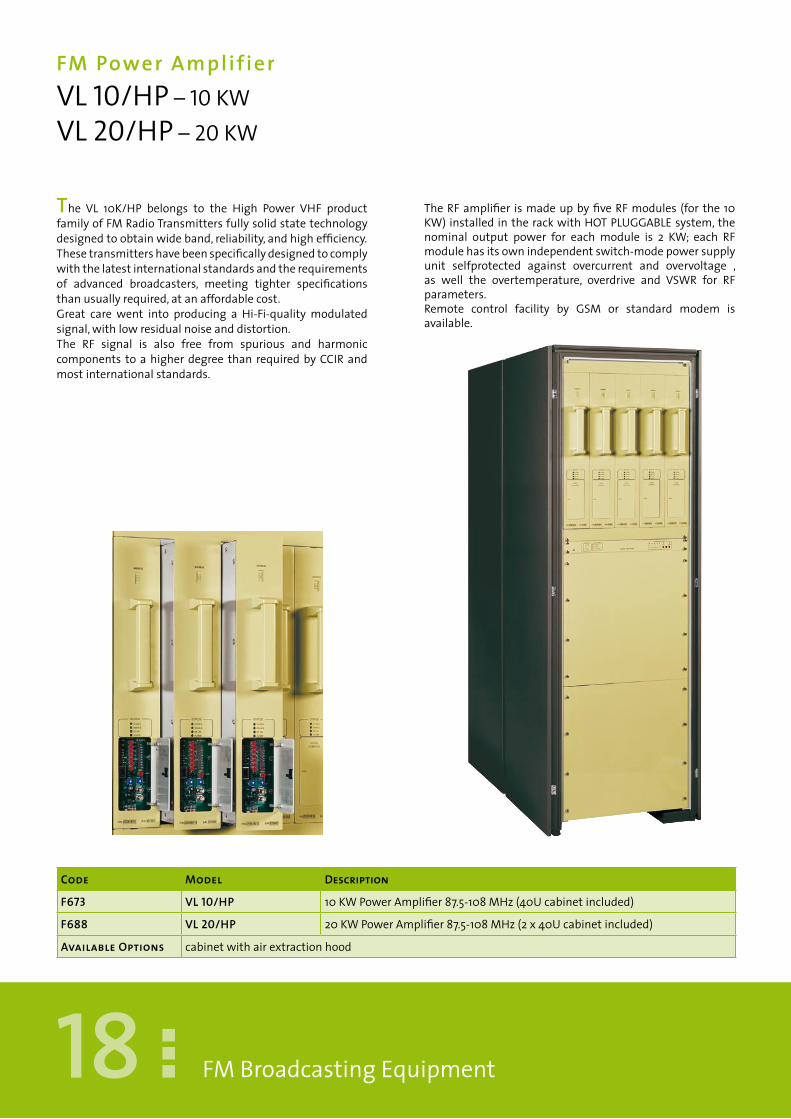
The VL 10K/HP belongs to the High Power VHF productfamilyofFMRadioTransmittersfullysolidstatetechnologydesignedtoobtainwideband,reliability,andhighefficiency.Thesetransmittershavebeenspecificallydesignedtocomplywiththelatestinternationalstandardsandtherequirementsof advanced broadcasters, meeting tighter specificationsthanusuallyrequired,atanaffordablecost.Great care went into producing a Hi-Fi-qualitymodulatedsignal,withlowresidualnoiseanddistortion.The RF signal is also free from spurious and harmoniccomponents toahigherdegree than requiredbyCCIRandmostinternationalstandards.
Code Model Description
F673 VL �0/HP 10KWPowerAmplifier87.5-108MHz(40Ucabinetincluded)
F688 VL 20/HP 20KWPowerAmplifier87.5-108MHz(2x40Ucabinetincluded)
available Options cabinetwithairextractionhood
TheRFamplifier ismadeupbyfiveRFmodules (for the10KW)installedintherackwithHOTPLUGGABLEsystem,thenominal output power for each module is 2 KW; each RFmodulehasitsownindependentswitch-modepowersupplyunit selfprotected against overcurrent and overvoltage ,as well the overtemperature, overdrive and VSWR for RFparameters.Remote control facility by GSM or standard modem isavailable.

�9FMBroadcastingEquipment
SPECIFICATIONS VL10/HP VL20/HPrFoutputpower 10KW 20KWNr.ofTransistors 40MOS-FETBLF278 80MOSFETBLF278rFInput(NominalLevel) 20W 20WOutputConnector 1-5/8EIA 3-1/8EIADimensions(WxHXD)mm 600x2000x1200 600x2000x1200(2pcs)Weight 630Kg 1100KgPowerconsumption Approx.<19000VA Approx.<38000VAPowersupplyreq. three-phase380Vac±15% three-phase380Vac±15%Nr.ofpowersupplyboards 5DC/DC 10DC/DCNumberoffans 2blowersforeachPA&PSmodule 2blowersforeachPA&PSmodule
TechnicaldatarFOUTPUTSPECIFICATIONSRange 87,5÷108MHzOverallefficiency Betterthan52%ImpedanceRFConnector 50OhminputandoutputOutputpowerstability ±3%Harmonicssuppression ≥-70dBcSpuriousEmission <-90dBcResidualAsynchronyAM -60dBWeighedResidualSynchronyAM -50dBWeighedProbe BNCconnectorRF–60dBcPOWErSUPPLYType OnepowersupplyDC/DCeachRFmoduleProtections Overheating70°C(bymeansoftheGeneral
Controlstage)OverchargeShortCircuitontheoutputvoltageCrow–Barprotection:(Excessiveoutputvoltagelimit)ExcessivecurrentconsumptionoftheRFmoduleOver-voltage
DESIgNDATADisplayMeter Forwardpower-Reflectedpower-DCsupply
voltage-DCsupplycurrent-Powersupplytemperature-Poweramplifiervoltage
Protections RFAmplifierRFmoduleover-temperature70ExcessivereflectedpowerPermissibleVSWR≤1.5
Programmablelogicprotection TrimmerwhichselectstheRFalarmthresholdLogicprotectionsreset Manual,RemoteorAutomaticallyevery24
hours
Controls Mains-DB15ConnectorAlarm ExcessiveoutputSWR(redled)–Alarm(redled)
–Stand–by(yellowled)-Mains-DCout–ALCType SolidstatedirectFMfrequencyPre–emphasis Flator75or50μsrEMOTECONTrOLOutputConnector DB25FConnectorfortheRemotecontrol–DB
25MConnectorforequipmentcontrol-DB9Femaleprogrammable–DB15FConnectorforCheckPanel–DB37FConnectorforauxiliary
InputConnector Stand-bycommandResetcommand
STANDArDSCOMPLIANCERadiospectrum ETSI300-384EMC ETSI447Safety EN60950-EN60215TEMPErATUrENominalrange 0°to45°C(MeetsETS300019norms)Operatingrange -5°to45°CStoragerange -40°to70°CMaximumrelativeHumidity 90%@26°CnoncondensingMaxOperatingAltitude 2500mt.a.s.l.

20
Digital AudioProcessorCONDOR 50
FMBroadcastingEquipment
The CONDOR 50 is a 5 band digital audio processorintegrating a bass enhancer, a noise gate, a digital stereoenhancer,aMPXstereocoderandaRDScoder.TheCONDOR50hastwoRS232serialportsopticallyisolated(notopticallycoupled)whichassuremaximumimmunityfordisturbingnoisescomingfromotherequipment.The equipment is supplied with a PC control softwarefor both local and remote control, to greatly simplify themanagementtobroadcasters.Through a standard PC, the software allows the remote
monitoringandcontrolofalltheprocessorstages(startingfromthegenerationoftheMPXsignalatAGClevel)aswellasthestatementofthemessagesandinformationprovidedbytheRDSencoder.Bymeansofitsexclusivedesign,theCONDOR50allowsanextraordinary savingof space andmoney, since it includesfourdigitalunitsinasinglebox,thusavoidingcompatibilityproblemswiththeconnectiontoanytypeofequipmentandmanufacturers.
TheCONDOR50,fullydigitalunitbasedon9powerfulDSP,features:•5banddigitalprocessoroperatedby30factorypre-setsprogrammedcurves.•Editingupto10differentuserpre-sets(innon-volatilememory)personalisedequalizations,easilysaveableandrecallable.•Settingparameterstocreateauniquesound,whichwillidentifytheradiostationinanunmistakableway.Alternativeparametersthatcanbesetare:SuperBassType,SuperBassLevel,BassCompressor,Mid1Compressor,Mid2Compressor,Mid3Compressor,HighCompressor,BroadbandDensity,Brilliance.DigitalMPXclipperbuilt-inintotheStereocoder,assuringnoaudibleartefactsandaperfectcontrolofmaxfrequencydeviation.Digitalstereoenhancerwithsettingparameters,neededtoreachthepsychoacousticdesiredeffect.Thisintegratedfeatureallowsmaximumexpressionofstereophoniceffectandfullcontroloftheparameterswithoutaffectingthemodulationstability.
Code Model Description
F5�9.2 COnDOR 50 Digital5BandAudioProcessor
F5�9.04 COnDOR 50a Digital5BandAudioProcessorwithOptionA
F5�9.05 COnDOR 50B Digital5BandAudioProcessorwithOptionB
F5�9.03 COnDOR 50aB Digital5BandAudioProcessorwithOptionA+B
available Options: DigitalinputAES/EBU-DigitalcoderRDS-SPDIFopticalandcoaxial.

2�FMBroadcastingEquipment
SPECIFICaTIOnS COnDOR 50Powersupplies From220/230V(110/115Vinternalsetting);50-60Hz,singlephase.Dimensions(WxHXD)mm 482x44x352(570x130x420Package)Weight 6Kg(7Kg.Package)Outputfiltercharacteristics LowPass15KHz(FIR-84Taps,15KHz/-0.1dB,17KHz/-70dB)OutputConnectors TypeXLRmaleConversion 24bitCodecConfiguration Pre-emphasized(50μsor75μs)internalorexternalOutputLevel -4dButo20dBu(Adjustablewith1dBuSteps)OutputImpedance 600OhmbalancedEMIsuppressedInput/OutputDelay <1.5msec.Tonegeneration 1KHz,Ref100%Modulation
TechnicaldataINPUTSIgNAL
ANALOgUEINPUT DIgITALINPUTConversion 24bit Connectors TypeXLRfemaleOptical
standardconnectortos-link
Connectors TypeXLRfemale Formats AES/EBU,S/PDIF,IEC60958,EIAJCP1201
Sensitivity -30dButo22dBu SampleRates
32KHz/44.1KHz/48KHz/96Khzwithautomaticselectionandjittercorrection
MaximumInputLevel
22dBu Connectors TypeXLRfemaleinputandOpticalinput
Impedance 600Ωbal.or10KΩunbal.,MI–suppressed
AGCRange ±20dB
AGCGainOffset
±6dB AGCSpeed Adjustablefrom0to6dB/sec.
AGCRange ±20dB rDSINPUTAGCSpeed Adjustablefrom0to6
dB/secInput -40to0dBmfor±2KHz
ofmaincarrierBY-PASSMODE(AnalogueInput,AgC=Off,gainOffset=0dB,OutputLevel=0dB)
Impedance 10KΩ
Connectors BNCfloatingoverchassis,EMIsup.
FrequencyResponse
20Hz÷21KHz(±0.3dB)
SCAINPUT
OutputNoise
-102dB(A-weighted) Input -40to0dBmfor±2KHzofmaincarrier
TotalHarmonicsDistortion
0.005% Impedance 10KΩ
TotalHar-monicsDistortion+Noise
-95dB Connectors BNCfloatingoverchassis,EMIsup.
PassBandRipple
±0.01dB
INPUTFILTErCHArACTErISTICSHighPass 30Hz(IIR-4thOrder)SIGNALPROCESS(FiveBandsProcessAlgorithm)Filters
BandPass30Hz÷200Hz(IIR-4thOrder-Butterworth)BandPass200Hz÷1.5KHz(IIR-4thOrder-Butterworth)BandPass1.5KHz÷4.8KHz(IIR-4thOrder-Butterworth)BandPass4.8KHz÷9.5KHz(IIR-4thOrder-Butterworth)BandPass9.5KHz÷15Hz(IIR-4thOrder-Butterworth)BassEnhancerFilter(Programmable)HFLimiterFilter:(IIR2nd,6KHz)HighFrequencyDenoiser:ThresholdAdjustable-51÷-80dB
LowPass 15KHz(FIR-84Taps,15KHz/-0.1dB,17KHz/-70dB)
Control SuperBassType(DiscoSoftBass,ClubLongBass,TightHardBass)SuperBasslevel(0÷+12dB)BassLevel(±6)Mid1Level(±6)Mid2Level(±6)Mid3Level(±6)HighLevel(±6)BroadbandDensity(0÷+12dB)Pre-set:30pre-setfactoryprogrammedand10user-editable
rEMOTECONTrOL(2xrS232opticallydecoupled)
STErEOENHANCErMODULE(Controls)
SatelliteDate 4800baud EffectDeph EffectDeph
PCHostCommunications
19200Baud EffectBand 3KHz/5KHz/8KHz/15KHz
ControlLinkMode
38400Baud EffectLevel -29dButo–6dBu
MPXMODULE rDSMODULE(standardsEBUservice)
Conversion 16bitPilotFrequency 19KHz±0.001% PS ProgramService
NamePilotInjection Adjustablefrom
–26dBto–14dBPI ProgramIdentifier
PilotPhase Adjustable6degrees
PTY ProgramType
S/N >90dB TA TrafficAnnouncement
StereoSeparation >65dB TP TrafficProgramCross-talkMaintoSub
>65dB M/S Music/Speech
Cross-talkSubtoMain
>65dB AF AlternativeFrequency
38KHzSubcarrierSuppression
>75dB RT RadioText
Compositeoutputlevel
-∞to+12dB PIN Program
Impedance 50Ohm DI DecoderIdentifierOutputConnectors
BNCfloatingoverchassis,EMIsup.
IH InHouseApplications
Pilotreferenceoutput
TTLLevelWave EM EmergencyMessages
Pilotreferencephaseerror
±8degrees

22
radioDataSystemencoderCR 102
FMBroadcastingEquipment
TheCR102isafriendlyusedynamicRDSencoderwhichsupportsallthemostpopularservicesandfeaturesusedbyBroadcasters.Theequipmentprovides:-Full-DigitalRDScodertotalsoftwareremotecontrol-AdvanceddynamicPSmanagement(i-PStechnology)-Easyinterfacetoharddiskautomationsystems
RDScharacterscustomizablefordifferentCountries-DedicatedSWinterfaceforDJandannouncers.TheCR102specificationsandbenefitshavebeenaccuratelydesignedtosatisfythemostdemandingrequirementsconcerningtheRDSgenerationinthebroadcastingfield.
Usingstate-of-art,high-speedDSPtechnology,CR102ensuresthepurestmodulationquality(thewholeprocessingisperformedbyphaselinearfilters).Itsdigitalarchitecturealsoguaranteeslongtermreliabilityandeasyfirmwareupdates.ApowerfulPCcontrolsoftwareisintegratedintheequipment.TheCR102allowsthecontrolandsettinginaneasyandintuitivewayofallRDSdataandofsignalgenerationparameters(levelandphase,synchronismsource,etc).Thebasicsoftwarescreen,alwaysdisplaysinrealtimePSandRTcontentcurrentlyonair,allowingafullandimmediatemonitoringofRDSbroadcasting,evenwhenanFMtunerisnotavailable.Asoftwaremoduleavailableasanoption(i-PStechnology),furtherbooststhenewPSmanagementfeatures:iteliminateseveryPSprogrammingconstraintleavingmaximumfreedomintermsofmessagelength,save/recallingfacilitiesandmessageeditingmasks.Anytextcanbeenteredandbroadcasted‘on-the-fly’,bothasafullPSsequenceorinascrollingmode.Furthermore,featuringatrueASCIIcommunicationprotocol,i-PSsoftwaremoduleenablestheCR102codertobeeasilyandquicklyinterfacedtoanyharddiskautomationsystem,forsongandartistidentificationonPSfieldsandmuchmore...!
Code Model Description
F827 CR �02 DigitalRadioDataSystem(RDS)Coder
F827.0� CR �02-IPS DigitalRadioDataSystem(RDS)CoderwithInstantPS
available Options InstantsPSsoftware-USBCommunicationinterface1USB+1RS-232port

23FMBroadcastingEquipment
TechnicaldatarDSMODULATIONSSignalgeneration MeetsorexceedsallCENELECEN50067(1998)
requirementsSub-carrierfreq. 57kHz±3HzBandwidth ±2.5kHz(-60dB)/±3.0kHz(-80dB)Synchronization toext.pilottoneorMPXsignalAutomatic
switchovertoint.osc.incaseofabsenceorlowqualityoftheextref.signal
RDSoutputlevel 0÷1200mVpp(5mVppsteps)LinearDistortion 0.01dBRDSphase ±120deg(reftoMPXpilot).1degstepExtMPXsummation ReftoAUXIN1&2specificationsAUXINPUT(1and2)Connector TypefloatingBNC,EMIsuppressedPass-throughLevel -40dB÷+20dBtrimadj.max24VppinpDistortion <0.03%Frequencyresponse 30Hz÷80KHz+/-0.1dBInputImpedance >10KohmPurpose widebandMPX,SCA,RDSinputsSYNC-IN&SYNC-OUTConnector TypefloatingBNC,EMIsuppressedSync-In TTLforRDSsynch.(ETScompliant)Sync-Out NotUsed
rDSPrOgrAMMINgCommandformats complianttoUECPForumdocumentSPB
490(Version5.1-22.08.97)+extendedmanufacturer‘scommandslistASCIIinterfacefordynamicmodeonly
Staticservices DI,PI,TP,TA,M/S,RT,AF,PS,PTYDynamicservices PSSEQUENCE,PSSCROLLINGRDSgroups 0A(75%),2A(25%)–FIXEDSEQUENCE(0A,0A,
0A,2A)Charactertables ISO8859-1(Latin1),8859-2(Latin2),8859-5
(Cyrillic),8859-7(Greek),8859-9(Turkish),8859-10(Nordic)
AFlists 24,containingupto25freqeachonePS(basicversion) 8pagescontaining20PSeachone+
1Scrollingmessage-24hours/dayschedulingcapabilities
RT 8,with24HoursDayschedulingcapabilitiesPS(i-PSoption) 8pagescontaining48PSeachone+32
scrollingmessages–instantbroadcastingcapabilities(upto384dynamicPSincludessoftwarededicatedinterfaceforDJandASCIIprogrammingsupport)
rEMOTECONTrOLOutputConnector 2xRS-232ConnectionRate 19200BaudCommunication DedicatedRemoteControlsoftware(supplied)
forWin95,98,XP,NT,2000accordinglytoUECP.SPB490(5.1)ASCIIInterface(withi-PSoptioninstalled)
InputConnector 3,optoinsulatedConnector SubD15pin,femalePurpose TP,TA,M/SflagswitchingTEMPErATUrENominalrange 0°to45°C(MeetsETS300019requirements)
SPECIFICaTIOnS CR�02OutputConnector typefloatingBNC,EMIsuppr.(50Ohm)Dimensions(WxHXD)mm 482x44x352(570x130x420Package)Weight 10Kg(12.6Kg.Package)Powerconsumption Approx.<10VANumberofpowersupplies From220/230V(110/115Vinternalsetting);50-60Hz,singlephase.DCPowerSupply 24VNumberoffans 1blower220Vac

24
DABVHFBand I I I &L BandTransmitterDAB 04
FMBroadcastingEquipment
ThisnewandfullyintegratedtransmitterforDABapplicationshasbeenrealizedin1Urackspaceonly,makingitsdesigntrulyunique.TheequipmenthasbeencarefullydesignedtosatisfytheneedsoftheprofessionalBroadcasters,inperfectcompliancewiththerevolutionnowtakingplaceworldwideinbroadcastingDigitalRadio.TherobustandeffectiveRFmodulationtechnology,
providesthebenefitofsuperiorcoverageinnon-lineofsightsituationsoreveninmobileenvironmentswithseveremulti-pathinterferences.TheDAB04includesallthesubsystemsofastandardDABtransmitterVHFbandIIIorLBand.OurDABSeriesmediumpowerRadioTransmitterscanbematchedwithVHFBandIIIpoweramplifiers,orwithLBandpoweramplifiers.
-ETS300401,300799andEU147compliant-DigitalIQ(ETS300798),IFandRFoutputs-T1andE1inputratessupported-Programmablestaticdelayfrom39msecto1.6seconds-DigitalPre-corrector-SNMPremotecontrolprovidedasanoption-RS232andRS485controlprovidedasanoption-InternalGPSreceiverprovidedasanoption-AutoSingleFrequencyNetworksetupfunction
Code Model Description
F900 DaB 04 ProfessionalDABModulatorIFoutput
available Options IntegratedGPSreceiver

25
SPECIFICaTIOnS DaB 04IFoutputlevel adjustable-10to0dBmOutputConnector 3xNTypeFemale50OhmDimensions(WxHXD)mm 482x44x483Weight 6KgPowerconsumption Approx.<25VANr.ofpowersupplyboards 1from230Va.c.±20%
FMBroadcastingEquipment
TechnicaldataFrEQUENCYRange VHFBandIII:Channel5Ato13F(174.928to
239.200MHz)LBand:1450–1550MhzDelaycompensation Upto1.6Secondsinstepsof488nsTransmitterOffsetDelay 0to2047microsecondsNetworkPaddingDelay 0to1SecondAutomaticallyadjustedforeach
NAinput.Settingmode 488nSstepsrFOUTPUTSPECIFICATIONSMode Mode1 Mode2 Mode3 Mode4ProcessingDelay 111000uS 39000uS 39000uS 63000uSTransmitterTrimmingDelay 111000to
200000uS39000to120000uS
39000to120000uS
63000to150000uS
RFStabilityMFN +/-10Hz +/-40Hz +/-80Hz +/-20HzRFStabilitySFN <10Hz <40Hz 3<80Hz <20HzStabilityofFrequency 1Hzover3months
Shoulder <45dBc(typically)Probe BNCconnectorRF–40dB;BNCconnectorLFINPUTPArAMETErSInputconnector/Impedance 10KOhmunbal.,2xBNCfemaleConnectorSelection DualNAordualNI(AutomodeInhibited)
Automaticmode(seamlessredundancyswitchoverbetweenNAinput1&NAinput2)
Type ETI(NI)2.048MHzshorthaulorETI(NA)protocolswithsupportforeitherT1orE1
InputErrorconditionsCRCViolations
UserselectableParameterstodefineOutputmuting(on-offandlevel)1)mutingoff-on2)numberofdetectederrorsfrom1to63)numberofframestobedetectedoverN=10to60
InputErrorconditionsResetperiod
UserselectableParametertodefinehowlongthemodulatorshouldwaitbeforerestoringitsoutput.numberofframestobeerrorfreeN=20to200
OUTPUTPArAMETErSInputconnector/Impedance 1DB25femaletypeDigitalI/Q8bitinterleaved
at4MHzOutputlevel ECL-10kStreamtiming AutoSelects:GPSaspreferencewithauto
switchovertointernal.GPS:LocksthereferencetoGPSreference.Internal:LocksthereferencetoInternalfrequencyreference.Inputstream1:Takesit’stimingfrominputstream1.Inputstream2:Takesit’stimingfrominputstream2.
AnalogueModulation DirectlyapplieddigitallyatIF.Numberofbits 15bitsusing64MHzsamples
DABMODEAllmodes SelectablefromtheETIstream(Auto)or
manualfromthefrontpanel.MNSCControl TransmitterOffsetDelay
TransmitterIdentificationInformationTIIDigitalLinearPre-correction Allowscorrectionoffrequencydomain
distortionTilt+/-3dB;Sag+/-3dB;S-Curve+/-2dB;GroupDelay+/-1uSec
DigitalNonLinearPre-correction
Correctsforthenonlinearcharacteristicofthetransmitter.3rdand5thorderamplitudeRange:0to99.993rdand5thorderphaseRange:-240to+240degrees
Memory 6setsofNonLinearfiguresPCStoredPeakclippingadjustment Rangeofbackoff:6-12dB.Differentialdelaybetweencarriers
Lessthan2.5uSecondsbetweenanycarrier
LocalControlInterface Interfaceno.1FrontpanelandkeypadPasswordprotectedInterfacestandardno.2:RS232,Type:DB9(M)Protocol:TBDPasswordprotected
Frequencyreferenceinput 10MHz,BNC50OhmTimereferenceinput 1PPS,BNC50OhmALArMInternalAlarms CompletelistTBD,GPSFailureofRFInput
InternalfailureRearPanelAlarmcontacts 10voltagefree,contacts.Highimpedance
indicatingaFaultLowimpedanceindicatingcorrectoperationUserconfigurablefromanyoftheavailableinternalalarmsUserconfigurableFilteringschemeofupto10secforeachalarm
rEMOTECONTrOLInput/OutputConnector Allfrontpanelcommandsavailable(Alarm,
Modulatorconfiguration)Ethernetinterface(option) ConnectorRJ46WEBbrowserorSNMPclientSTANDArDSCOMPLIANCEModulation ETSI300-401;OutofBandspuriousTBA;Center
carrierlevelTBAInterface ETSI300799EMC ETSI447Safety EN60950-EN60215TEMPErATUrENominalrange 0°to45°C(MeetsETS300019requirements)MaximumrelativeHumidity 90%noncondensingMaxOperatingAltitude 2500mt.a.s.l.
26
FMBrOADCASTINgDIgITALEXCITErDEX 30 - 30WDEX 100 - 100WDEX 250 - 250W
FMBroadcastingEquipment
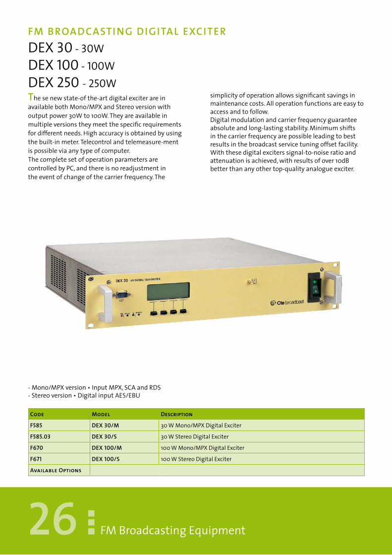
Thesenewstate-ofthe-artdigitalexciterareinavailablebothMono/MPXandStereoversionwithoutputpower30Wto100W.Theyareavailableinmultipleversionstheymeetthespecificrequirementsfordifferentneeds.Highaccuracyisobtainedbyusingthebuilt-inmeter.Telecontrolandtelemeasure-mentispossibleviaanytypeofcomputer.ThecompletesetofoperationparametersarecontrolledbyPC,andthereisnoreadjustmentintheeventofchangeofthecarrierfrequency.The
simplicityofoperationallowssignificantsavingsinmaintenancecosts.Alloperationfunctionsareeasytoaccessandtofollow.Digitalmodulationandcarrierfrequencyguaranteeabsoluteandlong-lastingstability.Minimumshiftsinthecarrierfrequencyarepossibleleadingtobestresultsinthebroadcastservicetuningoffsetfacility.Withthesedigitalexciterssignal-to-noiseratioandattenuationisachieved,withresultsofover10dBbetterthananyothertop-qualityanalogueexciter.
-Mono/MPXversion•InputMPX,SCAandRDS-Stereoversion•DigitalinputAES/EBU
Code Model Description
F585 DEX 30/M 30WMono/MPXDigitalExciter
F585.03 DEX 30/S 30WStereoDigitalExciter
F670 DEX �00/M 100WMono/MPXDigitalExciter
F67� DEX �00/S 100WStereoDigitalExciter
available Options

27
SPECIFICaTIOnS DEX 30 – DEX �00 DEX 250 DEX 30R – DEX �00R DEX 250RrFoutputpower 30W(100W) 250W 30W(100W) 250WOutputConnector NTypeFemale NTypeFemale NTypeFemale NTypeFemaleDimensions(WxHXD)mm 482x88x500 482x88x500 482x132x500 482x132x500Weight 13Kg 14Kg 23Kg 24KgPowerconsumption <200VA(<400VA) Approx.<750VA <200VA(<400VA) Approx.<750VAPowersuppliesrequ. 230Vac±15% 230Vac±15% 230Vac±15% 230Vac±15%Numberoffans 1blowers24Vdc 2blowers24Vdc 1blowers24Vdc 2blowers24Vdc
FMBroadcastingEquipment
Technicaldata
rFOUTPUTFrequencyBand 87.5÷108Mhz(adjustableby10kHzsteps)FrequencyStability ±1000Hzperyear,60Mhzinternalreference,
10MHzexternalreferenceRFMonitory 0,5Veffon50ΩBNC/FconnectorAMnoise ≥65dBnotweighted,referredto100%AMAMnoise ≥60dBweightedCCIR468-2,referredto100%
AMAMSynchronous ≥60dBwith500Hzfreq.Mod.and∆f±40kHz,
referredto100%AMIn-bandspurious ≥75dBcOut-bandspurious ≥90dBcHarmonicsattenuations >70dBcMODULATOrClassofemission FrequencymodulationF3EFrequencydeviation ±75kHz+3dBMaxdeviation ±75kHz+NdBwithN=0.5÷2presettable,
overmodulationdynamiccontrol,pre-settableswitch-offtime
Temperature 0÷45°CincharacteristicsTemperature -10÷+50°CinoperationRDSCODERstatic AccordingtoCENELECEN50067Specifications
withthefunctions,inEPROM,PI,PS,SCROLLPS,AF(1listof25frequencies)
MONO/MPXVErSIONCHArACTErISTICSAUX.1(MPX)InputBand 30Hz÷75kHzImpedance 600Ωor≥2kΩpre-settable-Balanced
-commonmoderejection≥40dB(50Hz÷100kHz)-Unbalancedpre-settable
Level ÷6dBoutput(4.36Vpp)with∆f±75kHz-Adjustment±6dBwith0.1dBsteps
Amplitude-frequency ≥±0.1dB(30Hz÷53kHz)-≥±0.2dB(53Hz÷100kHz)
Crosstalk ≥40dB(30÷100Hz)-≥45dB(40÷200Hz)-≥50dB(200Hz÷15kHz)(externalstereocoder)
Intermodulation d2≥0,05%d3≥0,05%(15Hz÷75kHz)Signal-to-Noiseratiounweighted
≥75dB(RMSvalue,de-emphasisincluded),referredto500Hzmodulfrequencyand∆f±75kHz(externalstereocoder)
Signal-to-Noiseratio ≥70dB(RMSvalue,de-emphasisincluded),ref.to500HzCCIRweighted-modulfreq.and∆f±75kHz(externalstereocoder)
Signal-to-Noiseratio ≥70dB(peakvalue,deemphasisincluded)referredto468-2CCIRweighted-500Hzmodulfreq.and∆f±75kHz(ext.stereododer)
Low-passfilters 15kHzMono-53kHzMPXStereo-72kHzMPXStereo+RDS75-90kHzMX+RDS+SCA
aUX. 2 (SCa) Input - aUX. 3 (RDS) InputBand 30Hz÷90kHzImpedance 600Ωor≥2kΩpre-settable-Balanced
-rejectioncommonmode≥40dB(50Hz÷90kHz)Presettablewhenunbalanced
Level 1Vppwith∆f÷3kHzAdjustment+6dBby0.1dBsteps
Amplitude-Frequency ≤±0.2dB(30Hz÷90kHz)Intermodulation d2≤0.05%d3≤0.05%(53÷90kHz)SCAMODULATOr(Option)-LFINPUTBand 30Hz÷7,5kHz
Impedance 600Ωor≥2kΩpre-settable-Balanced-rejectioncommonmode≥40dB(50Hz÷90kHz)Presettablewhenumbalanced
Level ±6dBmAdjustment±6dBby0.1dBstep∆f±7.5kHz
Pre-emphasis 50/75μs±0.2dBDistortion ≤±0.5%with∆f±6kHzSignal-to-Noiseratio ≥70dB(RMSvalue,pre-emphasisincluded),
referredtounweighted∆f±7.5kHzsubcarrierand∆f±6kHzofMF
SCA/STEREOCrosstalk ≥65dBreferredto∆f±6kHzofMFSTEREO/SCACrosstalk ≥75dBreferredto∆f±75kHzMODULATOrFrequency 60±85kHzMaxdeviation ±10kHzpresettableSTErEOVErSIONCHArACTErISTICS-AUX.3(AES/EBU)DigitalInput-AUX.2(LEFT)Analogicalinput-AUX.1(rIgHT)AnalogicalInputBand 30Hz÷15kHzImpedance 600Ωor≥2kΩpre-settable-Balanced
-rejectioncommonmode≥40dB(50Hz÷100kHz)Presettablewhenunbalanced
Low-passFilter 15kHz=0dB19kHz≥70dBLevel 6dBmwithdeviation±75kHzadjusment±10
dBby0.1dBsteps-Maxlevel+18dBmPre-emphasis 50or75μspre-settable-Tolerance(50Hz÷15
kHz)±0.1dBAmplitude-Frequency ≤±0.1dB(30Hz÷15kHz)referredto500HzTotalCrosstalk ≥50dB(30Hz÷10kHz)≥45dB(10KHz÷15
KHz)Distortion ≤±0.05%with∆f±75kHz(30Hz÷15kHz)Intermodulation d2≤0.05%d3≤0.05%with∆f±75kHz(5Hz
÷15kHz)Signal-to-Noiseratiounweighted
≥75dB(RMSvalue),referredto500Hzofmodulatedfrequencyand∆f±75kHz
Signal-to-NoiseratioCCIRweighted
≥70dB(RMSvalue),referredto500Hzmodulatedfrequencyand∆f±75kHz
Signal-to-Noiseratio468-2CCIRweighted
≥70dB(peakvalue),referredto500Hzofmodulatedfrequencyand∆f±40kHz
AuxiliaryFrequenciesDriverfrequency 19kHz±0.5HzDriveroutput 1Vp.p.sinusoidalorTTLSub-carrierfrequency 38kHz±1HzSub-carriersuppression ≥80dB

28
FMSol id StateAmplif ier &TransmitterVL 1000 PLUS – 1000 W VL 500 PLUS – 500 WTX 1000 PLUS – 1000 W TX 500 PLUS – 500 W
FMBroadcastingEquipment
TheVL1000PLUSisthenewandmodern1KWFMAmplifiermanufacturedbyCTEInternational.Theoptimalsolutionforthedesignwasfoundbyfollowingastate-of-the-artmanufacturingmethod,
andbyusinghighgainMOSFETtransistors.Thisnewsoundandcompactamplifierisabletosatisfytherequestsofallend-userswhoarelookingfortopqualityatacompetitiveprice.
Weight:only32Kg–foreasyhandlingandmaintenanceManagementsoftwareRemoteandLocalControlRS232/RS485ExtremelycompetitivepriceMono/MPXversion•InputMPX,SCAandRDSStereoversion•DigitalinputAES/EBU
Code Model Description
F636 VL500 PLUS 500WAmplifier87.5-108MHz(11Ucabinetincluded)
F636.0� VL500 PLUS 500WAmplifier87.5-108MHz
F603 VL�000 PLUS 1000WAmplifier87.5-108MHz(11Ucabinetincluded)
F603.0� VL�000 PLUS 1000WAmplifier87.5-108MHz
F685 TX 500 PLUS 500WStereo,MonoMPXTransmitter
F686 TX �000 PLUS 1000WStereo,MonoMPXTransmitter
available Options

29
SPECIFICaTIOnS VL 500 PLUS VL �000 PLUS TX 500 PLUS TX �000 PLUSrFoutputpower 500W 1000W 500W 1000WOutputConnector 7/16TypeFemale 7/16TypeFemale 7/16TypeFemale 7/16TypeFemaleDimensions(WxHXD)mm 482x220x600 482x220x600 482x220x600 482x220x600Weight 31Kg 32Kg 35Kg 36KgPowerconsumption Approx.<900VA Approx.<1800VA Approx.<975VA Approx.<1875VAPowersuppliesrequ. 230Vac±15%,singlephase; 230Vac±15%,singlephase; 230Vac±15%,singlephase; 230Vac±15%,singlephase;Numberoffans 2blowers24Vdc 2blowers24Vdc 2blowers24Vdc 2blowers24Vdc
FMBroadcastingEquipment
Technicaldata
FrEQUENCYrANgERange 87,5÷108MHzImpedance 50ΩinputandoutputpowerInputpower VL1000PLUS-Max20W;ALCsettingfrom500
Wto1KWVL500PLUS-Max10W;ALCsettingfrom250Wto500W
Overallefficiency Betterthan52%rFOUTPUTSPECIFICATIONSOutputpowerstability ±3%Harmonicssuppression ≥-80dBc(typicallybetterthan90dBc)SpuriousEmission <1mW(withoutModulation)ResidualAsynchronyAM -74dBWeighedResidualSynchronyAM -58dBWeighedRFPROBE -60dBcPOWErSUPPLYType Switchmode(Doubleconversionvoltagemains
direct)Protections Overheating70°C(bymeanstheGeneral
Control)Overcharge ShortCircuitoftheoutputvoltage Crow–Barprotection:(Exceedinghigheroutputvoltagelimit)Excessive“consumption”oftheRFmodule(25Amax.)Over-voltage(253Vmax.) Under-voltage(165Voff–187V0n)
DESIgNDATADisplayMeter Forwardpower:2KWf.s.withlog.scale
Reflectedpower:200Wf.s.withlog.Scale DCsupplyvoltage:50Vf.s.withlinearscale DCsupplycurrent:50Af.s.withlinearscale Powersupplytemperature Poweramplifiervoltage
ProtectionRFAmplifier RFmoduleover-temperature70 Excessivereflectedpower PermissibleVSWR≤1.5
Programmablelogicprotection Stoppingoftheunitafter8alarms Stoppingoftheunitafter16alarms
Logicprotectionsreset Manual,RemoteorAutomaticallyevery24hours
Controls MainsDB15Connector(Stand-byandResetcommand)
Alarm ExcessiveoutputSWR(redled)50Wadj.–Alarm(redled)-Stand–by(yellowled)Mains-DCout–ALC
rEMOTECONTrOL(BNCANDDB15CONNECTOrS)Connectors TypeBNCandDB15Input Stand-bycommand
ResetcommandAnalogoutput Signalproportionaltotheoutputvoltageofthe
powersupplymodule(1V÷10V)Signalproportionaltothecurrentsuppliedbythepowersupplymodule(1V÷10A)Signalproportionaltothesquarerootofthedirectpower(5V÷500W)Signalproportionaltothesquarerootofthereflectedpower(4V÷500W)
Digitaloutput “Stand-by”signal(contactisN.C.innormaloperations,connectedtoGNDinstand-bymode)“N.O.”alarmcontact(contactisnotconnectedinnormaloperation,connectedtopin15inalarm)“N.C.”alarmcontact(connectedtopin15inalarm,contactisnotconnectedinnormaloperation)
TEMPErATUrEAmbientrange 0°to45°C(operating-10°to50°)Storagerange -40°to70°CHumidity 90%@26°CAltitude <2500mt.abovesealevel

30
DVB-T / DVB-HModulator & regenerative Transposer &MIPInserterEM 010 EM 010TEM 010R EM 010A
TVBroadcastingDrivers
ThemodulatorEM010isdesignedtoconvertaTransportStream(MPEG-2)intoaCOFDMonafrequencybetween35and37MHz.ThegenerationandtransmissionofCOFDMsignalsat2kor8kispossiblewithQPSK,16QAMor64QAMmodulationwithpayloadsupto31.67Mb/s.EM010complieswithDVB-Hstandardthanksto4kIFFTmode,DVB-HsignallinginTPS-bits,cell-IDand8ksymbolinterleaveralsofor2kand4kmode.Thebuilt-inSFNinterfaceallowsoperationsinprecisionoffsetconditionswithfrequencylockontotheGPSreferencesignalandcompensationofthenetworkdelay.TheunitincludesastandardhierarchicalcapabilityanditisequippedwithtwoASIinputs.
TheEM010canitselfstoreuptotenlinearandtennon-linearcorrectioncurvesintheinternalmemory.Thenon–linearpre-correctorcompensatesthenon-linearityintroducedbyRFpoweramplifiers(gainandphasesvs.powerlevel),whilethelinearpre-correctorcompensatesthegroupdelayanddistortionscausedbyoutputfiltersandcombiners(levelandgroupdelayresponsevs.frequency).Thecorrectioncharacteristicsareset-upusinganintuitiveandeasytousegraphicaluserinterface,theIMDBuster,designedforstandardPCswithWindowsoperatingsystem.AWEBinterfacethatallowsremotecontrolthroughTCP/IPonEthernetisalsoavailableasoption.
TheEM010Tisacompleteagiletransmitter,thatcoversafrequencyrangefrom30MHzto1GHz.TheEM010RDigitalRe-ModulatorcoversapplicationstoreceiveaDVB-T/Hsignal,demodulatingthesignalcompletelytoMPEG-2TSleveltherebyutilizingthebuilt-inerrorcorrectioncapabilityofaDVB-T/HCOFDMsignaltoprovideacompletelyrestoredanderrorfreesignalthat,finally,ismodulatedontoafreshCOFDMspectrumforre-transmissiononauserselectablechannelinaccordancewiththerulesforchannelscodingandmodulationspecifiedintheDVB-T/Hstandard.TheEM010AisadeviceforinsertingMIPinformationintoatransportstream.TheEM010Amustbeinstalledattheheadendofthenetwork,beforethetransportstreamisdistributedtotheindividualtransmitter.InaccordancewiththeSFNstandard,thetiminginformationembeddedintheMIPisreferencedtoexternal10MHzand1PPSclockreferences.
Code Model Description
F843 EM 0�0 ProfessionalDVB-T/HModulatorIFoutput
F843.0� EM 0�0T 1mWrmsUHFAgileDVB-T/HDigitalTransmitter
F843.02 EM 0�0R 1mWUHFAgileRegenerativeTransposerDVB-T/H
F843.03 EM 0�0a MIPInserterDVB-T/H
available Options 6MHzBandwith-5MHzBandwith-RFconverter-WEBBrowser-SNMPclient-PrecisionTCXO(0,01ppm)-18dBmoutputclassAAmplifier-20dBattenuatorforprotectionofRFoutput

3�
SPECIFICaTIOnS EM 0�0 EM 0�0R EM 0�0aOutputpowerrms IFFrom-2to8dBm +0dBm(adj.+0/-10dB) -OutputConnector BNCTypeFemale50Ohm BNCTypeFemale50Ohm BNCTypeFemale50OhmDimensions(WxHXD)mm 482x44x483 482x44x483 482x44x483Weight 6Kg 6Kg 6KgPowerconsumption Approx.<25VA Approx.<25VA Approx.<25VANr.ofpowersupplyboards 1from230Va.c.±20% 1from230Va.c.±20% 1from230Va.c.±20%DCPowerSupply Notincluded Notincluded NotincludedTypeofventilation ForcedAir,2blowers ForcedAir,2blowers ForcedAir,2blowers
TVBroadcastingDrivers
TechnicaldataFrEQUENCYRange 30-1000MHzAdjustable(IF35-37MHz)InternalSettingmode 1HzstepsOutputfrequencystability FrequencystabilityLockedtoexternalreference
or1ppmreferenceInbandflatness ±0.1dB.OutputPowerstability ±0.5dBOutputReturnloss >16dBCOFDMMODULATOrInputsignal MPEG-2TransportStream
Inputdata(payloads) Ratefrom3.73to31.67Mbits/sinaccordingtoselectedBWandmode
Transportpacketlength 188bytes-204bytes(SPI)IFFT 2k,8Kand4k(DHB-H)Guardintervals 1/4,1/8,1/16,1/32Coderates 1/2,2/3,3/4,5/6,7/8Modulation QPSK,16QAM,64QAMPrecisionoffset Integrated(Exact1Hzsteps@allBW)SFNfunction IntegratedNetworkdelaycompensation AutomaticBandwidth 8MHz,7MHz,6MHz,5MHzEyeapertureonvectorconstellation
>32dB(w/oI.F.filter)
Virtualelasticstorefunctiontopreventdataoverflow
Integrated
Serialdatainput 2xASI,BNC75OhmFrequencyclockreferenceinput 10MHz,BNC50Ohm/>1kOhm,Level100mV
-3VppTimereferenceinput 1PPS,BNC50Ohm/>1kohm,Level0-5V,Trigger:
PositivetransitionReferenceoutput TSclocksignalHierarchicalmode 16-QAMand64-QAMinalpha-1,alpha-2and
alpha-4Spectruminversion Invertedandnoninvertedselectableviafront
panelmenuNon-linearcorrection Curveformats:S21andVO/VI
Amplitudescale:LinearandlogarithmicCorrectionpoints:Max256,user-definedpositionGaincorrection:Max12dB,subjecttoavailableheadroomPhasecorrection:-6to+30degrees,subjecttoavailableheadroom
Linearcorrection Correctionpoints:21Pointspacing:1/20ofnominalspectrumBWAmplitudecorrection:±10dBAmplituderesolution:0.01dBGroupdelaycorrection:±1000ns
Testfunctions ProgrammablecarrierpacketremovalCWmodeNullpacketonlystream
COFDMTrANSPOSErVErSIONInputFrequency 30-945MHz(1Hzstepsresolution)InputImpedance 50OhmN(Female)connectorInputfieldLevel(QEF=BER2E-4)
20dBuVto120dBuV@QPSK,CR1/236dBuVto120dBuV@64QAMCR7/8
InputReturnloss >10dBSelectivity Definedasthemaximumallowedlevelofthe
disturbingsignalrelativetothelevelofthewantedDVB-TsignalforQEFreceptionofthewantedsignal
OUTPUTSPECIFICATIONSBER ZerooverfivehourperiodbeforeRSdecodingMER >40dBSpectrumoutsideband +/-3,8MHz:0dB+/-4,25MHz:<47dB+/-
5,25MHz:<53dBHarmonicsemission <-50dBm(withoutputfilter)Spuriousemission <-50dBm(withoutputfilter)rEMOTECONTrOLOutputConnector RS232interfaceConnectorDB9Male–TwoDB9
Femaleprogrammableconnectors-Alarmsviaseparatefloatingrelays(commonmake-breakcontacts,contactrating60V/0.2A5Wmax)
InputConnector Resetandmutingcontrolactivatedbygroundclosure
Ethernetinterface(option) ConnectorRJ46WEBbrowserorSNMPclientSTANDArDSCOMPLIANCEModulationcharacteristics ETSI300-744EMC EN300-489-1EN301489-14Safety EN60950-EN60215TEMPErATUrETemperatureOperatingrange 0°to50°C(MeetsETS300019requirements)MaximumrelativeHumidity 90%noncondensingMaxOperatingAltitude 2500mt.a.s.l.

32
TVAnalogueProfessional ModulatorEMA 010
TVBroadcastingDrivers
TheEMA010televisionmodulatorisahighperformancedevicewhichmeetsthestrictesttechnicalrequirementsnecessarytoobtainareallyoutstandingqualityoftheTelevisionSignal.ItisavailableindifferentversionsforthePAL,SECAM,NTSCworldstandards.Theequipmentisasingle19”1Uheightmainframe:insideit,eachmoduleislocatedinasealed
aluminiumcaseforanoutstandingshieldprotectionandeasyremovingforquickservice.Afrontpanelmultifunctiondisplayisavailabletomonitorallthemainparametersthatcanbeeasilysetbymeansofakeyboardplacedonthefrontpaneloftheequipment.
-MultifunctionGraphicDisplay-SAWVestigialFilter-SynchronismRegenerator-GroupDelayand8-cellsPre-corrector(excludible)-AutomaticWhiteandSynchronism-LimitationCircuit-Multi-standardModulator-DifferentialPhasePre-CorrectorandICPM
Code Model Description
F858 EMa 0�0/E ProfessionalTelevisionMonoIFoutputModulator
F858.0� EMa 0�0/ES ProfessionalTelevisionStereoIFoutputModulator
F858.02 EMa 0�0/EK ProfessionalTelevisionMonoSECAMIFoutputModulator
F858.03 EMa 0�0/ESK ProfessionalTelevisionStereoSECAMIFoutputModulator
available Options Stereo/DualSoundVersions

33
SPECIFICaTIOnS EMa 0�0IFoutputpower From-2to8dBmOutputConnector BNCTypeFemaleDimensions(WxHXD)mm 482x44x483Weight 6KgPowerconsumption Approx.<25VANr.ofpowersupplyboards 1from230Va.c.±20%DCPowerSupply 48VTypeofventilation ForcedAir
TVBroadcastingDrivers
TechnicaldataVIDEOPArAMETErSInputconnector BNCtypeconnectorInputimpedance 75OhmInputlevel 1Vp.p.±6dBKfactor <1%Tilt <1%Frequencyresponse ±0.5dB(ontheentirevideoband)Differentialgain <±1%
Differentialphase <±2°IFOutputimpedance 50OhmIFNicam Optional33.050MHz(othersuponrequest)Inputreturnloss <0–30dBGroupdelay ±50ns(Withinthevisionband)S/Nratio(weighted) >68dB(weightedaccordingtoCCIR)
>60dB(unweightedaccordingtoCCIR)Pre–emphasis Flator75or50μsLuminanceNonLinearity <±2%Framedistortion <2%Linedistortion <2%VisionIF 38,9MHz
AUDIOPArAMETErSInputconnector XLRtypemaleconnectorInputimpedance 600Ohm(balanced)or>10kOhm
(unbalanced)( jumperselectable)Inputlevel 0dBm±8dB0.5stepFrequencyresponse(30Hz-15kHz)
±0.5dB(±0.2dBtypically)
Audiopre-emphasis Flator75or50μs
Distortion(30Hz-15kHz) <0.3%S/Nratio(un-weighted) >50dBunweightedfor50KhzdeviationStereo/Dualmode AvailableStereoSeparation >37dB(betterthan40dBtypically)AudioIF 33,4MHzand33,1578MHzrEMOTECONTrOLOutputConnector RS232interfaceConnectorDB9Male–RS485
-Analog&DigitalcontactInputConnector EnablingSTANDArDSCOMPLIANCEFrequencySpectrum EN302296–EN302297EMC EN300-489-1EN301489-14Safety EN60215TEMPErATUrETemperatureOperatingrange 0°to50°C(MeetsETS300019requirements)MaximumrelativeHumidity 90%noncondensingMaxOperatingAltitude 2500mt.a.s.l.

34
DVB-T/ DVB-HTransmitter ®enerativeTransposerE 05-DU – 5 W E 10-DU – 10 WE 02-DU – 2,5 W E 01-DU – 1 W
TVBroadcastingDrivers
TheE10-DUdigitaltransmitterisdesignedtoconvertaTransportStreamintoaCodedOrthogonalFrequencyDivisionMultiplex(COFDM)withanoutputpowerof10Wrms.ThegenerationandtransmissionofCOFDMsignalsat2k,4kor8kispossiblewithQPSK,16QAMor64QAMmodulationwithpayloadsfrom3,73to31.67Mb/s.Thankstoaninternal32-bitprocessor,theinnovativesoftwareimplementedintheequipmentallowstheelaborationofazeroerrorsignal.TheintegratedSFNinterfaceallowsoperationsinprecisionoffsetconditionswithfrequencylockonto
theGPSreferencesignalandcompensationofthenetworkdelay.TheunitincludesastandardhierarchicalcapabilityanditisequippedwithfourASIinputsinDualASIbothforuniformmodulationandhierarchicalmodulation.Thefriendlyuseofthisdigitaltransmitter,thesturdinessofthemodularconstructionanditshighperformancecapability,openupnewperspectivesabouttherealizationofDVB-T/HnetworksbothinSFNandMFNapplications.AWEBinterfacethatallowsremotecontrolthroughTCP/IPonEthernetisavailableasoption.
CompliantwithETS300744requirementsChannelBandwidth6,7,8MHzalluniformDVB-Hsupportthanksto4kIFFTmode,Cell-idand8ksymbolinterleaverSuperiorlinearandnonlineardigitalpre-corrector.DualASIforeachinput(LP&HP)
MIPdecoderforautomaticconfigurationDe-jitteroninputsignalpriortotransmissionGPSreferencelocksignalSuperiorMERperformance(designedtomeet45dB)Allredundancyconfigurationsavailableonrequest(Dualdriver;activereserve;N+1;1+1)
Code Model Description
F885.02 E 0�-DU 1WrmsUHFDVB-T/HDigitalTransmitter(4Uoutfilterincl.)
F885.0� E 02-DU 2,5WrmsUHFDVB-T/HDigitalTransmitter(4Uoutfilterincl.)
F885.03 E 05-DU 5WrmsUHFDVB-T/HDigitalTransmitter(4Uoutfilterincl.)
F885.04 E �0-DU 10WrmsUHFDVB-T/HDigitalTransmitter(4Uoutfilterincl.)
available Options 6MHzBandwith-5MHzBandwith-RF Agileconverter–GPSReceiver- WEBBrowser-SNMPclient-PrecisionTCXO(0,01ppm).

35
SPECIFICaTIOnS E 0�-DU E 02-DU E 05-DU E �0-DUrFoutputpower 1Wrms 2,5Wrms 5Wrms 10WrmsOutputConnector NTypeFemale NTypeFemale NTypeFemale NTypeFemaleDimensions(WxHXD)mm 482x132(+44)x450 482x132(+44)x450 482x132(+44)x450 482x132(+44)x450Weight 15Kg 15Kg 15Kg 15KgPowerconsumption Approx.<400VA Approx.<400VA Approx.<400VA Approx.<400VANr.ofpowersupplyboards 1from230Va.c.±20% 1from230Va.c.±20% 1from230Va.c.±20% 1from230Va.c.±20%DCPowerSupply 48V(36-60V) 48V(36-60V) 48V(36-60V) 48V(36-60V)Numberoffans 2blowers,24Vdc 2blowers,24Vdc 2blowers,24Vdc 2blowers,24Vdc
TVBroadcastingDrivers
TechnicaldataFrEQUENCYRange UHF(470-860MHz)
VHFBandIII(174-260MHz)InternalSettingmode 1HzstepsOutputfrequencystability FrequencystabilityLockedtoexternalreference
or1ppmreferenceor1ppmInbandflatness ±0.1DbImpedanceRFConnector 50OhmTrANSPOSEr/rEgENErATIVEVErSIONInputFrequency UHF(470-860MHz)-VHFBandIII(174-260
MHz)-VHFBandI(45-90MHz)InputImpedance 50OhmN(Female)connectorInputMatching >26dBInputLevelAmplitude -30to–75dBmrFOUTPUTSPECIFICATIONSOutputPowerstability ±0.5dBIntermodulationdistortion <-60dBatratedoutputpower(Withpre-
correctioninserted)Harmonicsemission <-75dBc(withoutputfilter)Spuriousemission <-75dBc(withoutputfilter)ImpedanceRFConnector 50OhmBER ZerooverfivehourperiodbeforeRSdecodingMER >37dBProtections Overpower,Overvoltage,Overcurrent,Over
temperatureProbe IFmonitorSMAconnector(36.15Mhz)COFDMMODULATOrInputsignal MPEGTransportStreamInputdata rate3.73to31.67Mbits/s(accordingtoselected
BWandmode)Transportpacketlength 188bytes-204bytes(SPI)IFFT 2k,8Kand4k(DHB-H)Guardintervals 1/4,1/8,1/16,1/32
Coderates 1/2,2/3,3/4,5/6,7/8Modulation QPSK,16QAM,64QAMPrecisionoffset Integrated(Exact1Hzsteps@allBW)SFNfunction IntegratedNetworkdelaycompensation AutomaticBandwidth 8MHz,7MHz,6MHz,5MHzEyeapertureonvectorconstellationw/oI.F.filter
>32dB
Virtualelasticstorefunctiontopreventdataoverflow
Integrated
Serialdatainput 4xASI,BNC75OhmFrequencyreferenceinput 10MHz,BNC50OhmTimereferenceinput 1PPS,BNC50OhmReferenceoutput TSclocksignalHierarchicalmode Integrated,aIImodessupportedSpectruminversion SupportedTestfunctions ProgrammablecarrierpacketremovalCWmode
NullpacketonlystreamrEMOTECONTrOLOutputConnector RS232interfaceConnectorDB9Male–TwoDB9
Femaleprogrammableconnector-Alarmsviaseparaterelays
InputConnector Resetandmutingcontrolactivatedbygroundclosure
Ethernetinterface(option) ConnectorRJ46WEBbrowserorSNMPclientSTANDArDSCOMPLIANCEFrequencySpectrum EN302296–EN302297EMC EN300-489-1EN301489-14Safety EN60215TEMPErATUrETemperatureOperatingrange 0°to45°C(MeetsETS300019requirements)MaximumrelativeHumidity 90%noncondensingMaxOperatingAltitude 2500mt.a.s.l.

36
DVB-T/ DVB-HTransmitter ®enerativeTransposerEK 50-DU – 50 W
TVBroadcastingDrivers
TheEK50-DUSeriesdigitaltransmitterisdesignedtoconvertaTransportStreamintoaCodedOrthogonalFrequencyDivisionMultiplex(COFDM)withanoutputpowerof50Wrms.ThegenerationandtransmissionofCOFDMsignalsat2k,4kor8kispossiblewithQPSK,16QAMor64QAMmodulationwithpayloadsfrom3,73to31.67Mbits/s.Thankstoaninternal32-bitprocessor,theinnovativesoftwareimplementedintheequipmentallowstheelaborationofazeroerrorsignal.TheintegratedSFNinterfaceallowsoperationsinprecisionoffsetconditionswithfrequencylockonto
theGPSreferencesignalandcompensationofthenetworkdelay.TheunitincludesastandardhierarchicalcapabilityanditisequippedwithfourASIinputsinDualASIbothforuniformmodulationandhierarchicalmodulation.Thefriendlyuseofthisdigitaltransmitter,thesturdinessofthemodularconstructionanditshighperformancecapability,openupnewperspectivesabouttherealizationofDVB-T/HnetworksbothinSFNandMFNapplications.AWEBinterfacethatallowsremotecontrolthroughTCP/IPonEthernetisavailableasanoption.
ComplieswithETS300744requirementsChannelBandwidth6,7,8MHzalluniformDVB-Hsupportthanksto4kIFFTmode,Cell-idand8ksymbolinterleaverSuperiorlinearandnonlineardigitalpre-corrector.IntegratedDualASIforeachinput(LP&HP)MIPdecoderforautomaticconfigurationDe-jitteroninputsignalpriortotransmissionGPSreferencesignallockSuperiorMERperformance(designedtomeet45dB)Allredundancyconfigurationsavailableonrequest(Dualdriver;activereserve;N+1;1+1)Code Model Description
F885.05 EK 50-DU 50WrmsUHFDVB-T/HDigitalTransmitterCOMPACT
available Options 6MHzBandwith-5MHzBandwith-RF Agileconverter–GPSReceiver- WEBBrowser-SNMPclient-PrecisionTCXO(0,01ppm).

37
SPECIFICaTIOnS EK 50-DUrFoutputpower 50WrmsOutputConnector NTypeFemaleDimensions(WxHXD)mm 482x132(+44)x450Weight 28KgPowerconsumption Approx.<600VANr.ofpowersupplyboards 1;230Vac±20%DCPowerSupply 48V(36-60V)
TVBroadcastingDrivers
TechnicaldataFrEQUENCYRange UHF(470-860MHz)
VHFBandIII(174-260MHz)InternalSettingmode 1HzstepsOutputfrequencystability FrequencystabilityLockedtoexternalreference
or1ppmreferenceor1ppmInbandflatness ±0.1DbrFOUTPUTSPECIFICATIONSOutputPowerstability ±0.5dB
Intermodulationdistortion <-60dBatratedoutputpower(Withpre-correctioninserted)
Harmonicsemission <-75dBc(withoutputfilter)Spuriousemission <-75dBc(withoutputfilter)ImpedanceRFConnector 50OhmBER ZerooverfivehourperiodbeforeRSdecodingMER >37dBProtections Overpower,Overvoltage,Overcurrent,Over
temperatureProbe IFmonitorSMAconnector(36.15Mhz)TrANSPOSEr/rEgENErATIVEVErSIONInputFrequency UHF(470-860MHz)-VHFBandIII(174-260
MHz)-VHFBandI(45-90MHz)InputImpedance 50OhmN(Female)connectorInputMatching >26dBInputLevelAmplitude -30to–75dBmCOFDMMODULATOrInputsignal MPEGTransportStreamInputdata rate3.73to31.67Mbits/s(accordingtoselected
BWandmode)Transportpacketlength 188bytes-204bytes(SPI)IFFT 2k,8Kand4k(DHB-H)Guardintervals 1/4,1/8,1/16,1/32
Coderates 1/2,2/3,3/4,5/6,7/8Modulation QPSK,16QAM,64QAMPrecisionoffset Integrated(Exact1Hzsteps@allBW)SFNfunction IntegratedNetworkdelaycompensation AutomaticBandwidth 8MHz,7MHz,6MHz,5MHzEyeapertureonvectorconstellationw/oI.F.filter
>32dB
Virtualelasticstorefunctiontopreventdataoverflow
Integrated
Serialdatainput 4xASI,BNC75OhmFrequencyreferenceinput 10MHz,BNC50OhmTimereferenceinput 1PPS,BNC50OhmReferenceoutput TSclocksignalHierarchicalmode Integrated,aIImodessupportedSpectruminversion SupportedTestfunctions ProgrammablecarrierpacketremovalCWmode
NullpacketonlystreamrEMOTECONTrOLOutputConnector RS232interfaceConnectorDB9Male–TwoDB9
Femaleprogrammableconnectors-Alarmsviaseparaterelays
InputConnector Resetandmutingcontrolactivatedbygroundclosure
Ethernetinterface(option) ConnectorRJ46WEBbrowserorSNMPclientSTANDArDSCOMPLIANCEFrequencySpectrum EN302296–EN302297EMC EN300-489-1EN301489-14Safety EN60215TEMPErATUrETemperatureOperatingrange 0°to45°C(MeetsETS300019requirements)MaximumrelativeHumidity 90%noncondensingMaxOperatingAltitude 2500mt.a.s.l.

38
DVB-T/ DVB-HTransposersE 10-UU – 10 W E 50-UU – 50 WE 10-VV – 10 W E 50-VV – 50 W
TVBroadcastingDrivers
ThisnewDVB-T/HDigitalTransposerandGap-fillerfamilyissuitableforapplicationsindigitalterrestrialbroadcastingofTVprograms,withtheclassicaltransposermethodwithrelayreceptionandnon
remodulationbroadcasting.AlltheequipmentcanbeconfiguredtooperatealsoforanalogueTVsystemconfiguration.
Compactdesign,modularconstruction,plug-inmodulesfromthefrontpanelLCDgraphicdisplayandsoftkeystocontrolthemoduleparametersSuperiorclassABpre-corrector,forbothdigitalandanalogueTVforhighpowertransmissionorsimplifiedclassApre-correctorforlowpowertransmissionUltralowphasenoiseLocalOscillatorModulesforrelayapplicationsBroadbandamplifiersHighreliability,longmaintenance-freeperiods,friendly-servicedesignAllredundancyconfigurationsavailableonrequest(Dualdriver;activereserve;N+1;1+1)WEBmonitoringforremotecontrol
Code Model Description
F864 E 05-UU 5WUHFTransposerwithoutputfilter
F864.0� E �0-UU 10WUHFTransposerwithoutputfilter
F834 E �0-VV 10WVHFBandIIITransposerwithoutputfilter
F834.0� E �0-UV 10WVHFBandIIITransposerwithoutputfilter
F834.02 E 50-VU 50WUHFBandTransposerwithoutputfilter
F835 E 50-UU 50WUHFBandTransposerwithoutputfilter
available Options ProfessionalSAWfilter-PrecisionTCXO

39
SPECIFICaTIOnS E 05-UU E �0-UU E 50-UU E 50-VVrFoutputpowerrms 1W 2,5W 10W 10WrFoutputpowerPsync 5W 10W 50W 50WOutputConnector NTypeFemale NTypeFemale NTypeFemale NTypeFemaleDimensions(WxHXD)mm 482x132x450 482x132x450 482x132x450 482x132x450Weight 15Kg 15Kg 15Kg 15KgPowerconsumption Approx.<110VA Approx.<140VA Approx.<350VA Approx.<350VANr.ofpowersupplyboards 1:230Va.c.±15% 1:230Va.c.±20% 1:230Va.c.±20% 1:230Va.c.±20%DCPowerSupply 48V(36-60V) 48V(36-60V) 48V(36-60V) 48V(36-60V)Numberoffans 2blowers,24Vdc 2blowers,24Vdc 2blowers,24Vdc 2blowers,24Vdc
TVBroadcastingDrivers
TechnicaldataFrEQUENCYRange UHF(470-860MHz)-VHFBandIII(174-260
MHz)-VHFBandI(45-90MHz)Internalreferencefrequency 5MHz(or10MHz)Externalreferencefrequency InputFromthefront5MHz(or10MHz)Outputfrequencystability TCXO1p.p.m/year(opt.:OVEN<0.2p.p.m
/years)Frequencydrift Betterthan10exp-7Amplitude/frequencyresponseband
±0.5dBthroughoutthevision
rFOUTPUTSPECIFICATIONSOutputPowerstability ±0.5dB
Intermodulationdistortion <-60dBatratedoutputpower(Withpre-correctioninserted)
Harmonicsemission <-75dBc(withoutputfilter)Spuriousemission <-75dBc(withoutputfilter)ImpedanceRFConnector 50OhmGroupdelaydeviation ±30nswithinthevisionbandUpconverterA.G.C.dynamic >10dBSyncpulsecompression <3%Differentialgain <5°Differentialphase <3%MER Betterthan36dBPhasenoise -70dBc@10Hz;-85dBc@100Hz–1KHz;
-100dBc@10KHzProtections Overpower,Overvoltage,Overcurrent,Over
temperatureLoadmismatch 10dBProbe IFmonitorSMAconnector(36.15Mhz)
OffLockAttenuation >60dBcS/NRATIO(weighted) >73dB(referredto±75KHz)THD 0,10%VSWR Lessthen1,5:1TrANSPOSErVErSIONInputFrequency UHF(470-860MHz)-VHFBandIII(174-260
MHz)-VHFBandI(45-90MHz)InputImpedance 50OhmN(Female)connectorInputfieldLevel -30to-65dBmInputMatching >20dBSelectivity S.A.W.Filter50°CSynthesisResolution 1HzNoisefigure <8dBIFInputlevel -4dBm±0.5dBatRFinputdigital(0dBm±0.5
dBatRFinputanalog)Inputmatching VSWRbetterthan1.2:1inchannelrEMOTECONTrOLOutputConnector RS232interfaceConnectorDB9Male,RS485,
Auxiliaryport25-poleConnectorEthernetinterface(option) ConnectorRJ45WEBbrowserorSNMPclientSTANDArDSCOMPLIANCEFrequencySpectrum EN302296–EN302297EMC EN300-489-1EN301489-14Safety EN60215TEMPErATUrETemperatureOperatingrange 0°to45°C(MeetsETS300019requirements)Storagetemperature From-30°Cto+80°CMaximumrelativeHumidity 90%noncondensingMaxOperatingAltitude 2500mt.a.s.l.
40
DVB-T/ DVB-HTransposersEK 150-UU – 150 WEK 200-UU – 200 W
TVBroadcastingDrivers
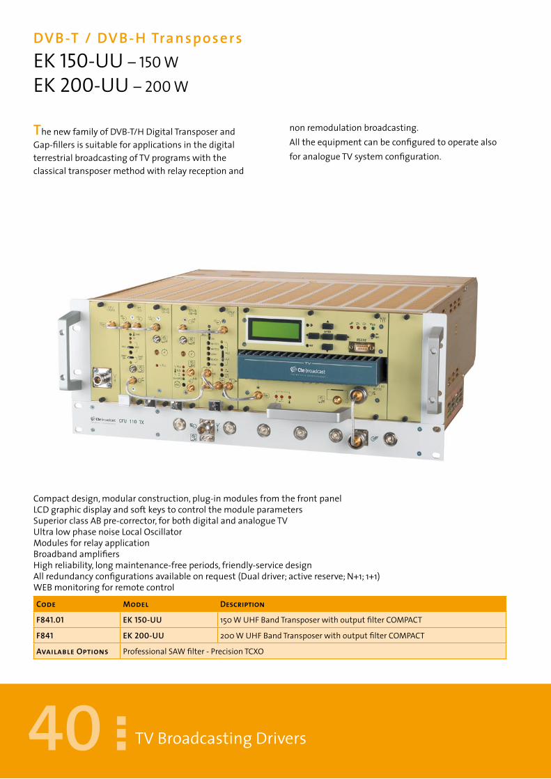
ThenewfamilyofDVB-T/HDigitalTransposerandGap-fillersissuitableforapplicationsinthedigitalterrestrialbroadcastingofTVprogramswiththeclassicaltransposermethodwithrelayreceptionand
nonremodulationbroadcasting.AlltheequipmentcanbeconfiguredtooperatealsoforanalogueTVsystemconfiguration.
Compactdesign,modularconstruction,plug-inmodulesfromthefrontpanelLCDgraphicdisplayandsoftkeystocontrolthemoduleparametersSuperiorclassABpre-corrector,forbothdigitalandanalogueTVUltralowphasenoiseLocalOscillatorModulesforrelayapplicationBroadbandamplifiersHighreliability,longmaintenance-freeperiods,friendly-servicedesignAllredundancyconfigurationsavailableonrequest(Dualdriver;activereserve;N+1;1+1)WEBmonitoringforremotecontrol
Code Model Description
F84�.0� EK �50-UU 150WUHFBandTransposerwithoutputfilterCOMPACT
F84� EK 200-UU 200WUHFBandTransposerwithoutputfilterCOMPACT
available Options ProfessionalSAWfilter-PrecisionTCXO
4�
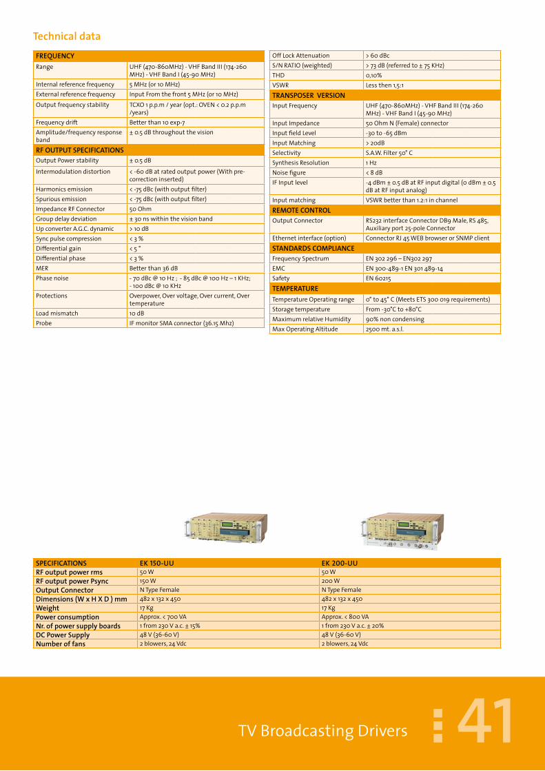
SPECIFICaTIOnS EK �50-UU EK 200-UUrFoutputpowerrms 50W 50WrFoutputpowerPsync 150W 200WOutputConnector NTypeFemale NTypeFemaleDimensions(WxHXD)mm 482x132x450 482x132x450Weight 17Kg 17KgPowerconsumption Approx.<700VA Approx.<800VANr.ofpowersupplyboards 1from230Va.c.±15% 1from230Va.c.±20%DCPowerSupply 48V(36-60V) 48V(36-60V)Numberoffans 2blowers,24Vdc 2blowers,24Vdc
TVBroadcastingDrivers
TechnicaldataFrEQUENCYRange UHF(470-860MHz)-VHFBandIII(174-260
MHz)-VHFBandI(45-90MHz)Internalreferencefrequency 5MHz(or10MHz)Externalreferencefrequency InputFromthefront5MHz(or10MHz)Outputfrequencystability TCXO1p.p.m/year(opt.:OVEN<0.2p.p.m
/years)Frequencydrift Betterthan10exp-7Amplitude/frequencyresponseband
±0.5dBthroughoutthevision
rFOUTPUTSPECIFICATIONSOutputPowerstability ±0.5dB
Intermodulationdistortion <-60dBatratedoutputpower(Withpre-correctioninserted)
Harmonicsemission <-75dBc(withoutputfilter)Spuriousemission <-75dBc(withoutputfilter)ImpedanceRFConnector 50OhmGroupdelaydeviation ±30nswithinthevisionbandUpconverterA.G.C.dynamic >10dBSyncpulsecompression <3%Differentialgain <5°Differentialphase <3%MER Betterthan36dBPhasenoise -70dBc@10Hz;-85dBc@100Hz–1KHz;
-100dBc@10KHzProtections Overpower,Overvoltage,Overcurrent,Over
temperatureLoadmismatch 10dBProbe IFmonitorSMAconnector(36.15Mhz)
OffLockAttenuation >60dBcS/NRATIO(weighted) >73dB(referredto±75KHz)THD 0,10%VSWR Lessthen1,5:1TrANSPOSErVErSIONInputFrequency UHF(470-860MHz)-VHFBandIII(174-260
MHz)-VHFBandI(45-90MHz)InputImpedance 50OhmN(Female)connectorInputfieldLevel -30to-65dBmInputMatching >20dBSelectivity S.A.W.Filter50°CSynthesisResolution 1HzNoisefigure <8dBIFInputlevel -4dBm±0.5dBatRFinputdigital(0dBm±0.5
dBatRFinputanalog)Inputmatching VSWRbetterthan1.2:1inchannelrEMOTECONTrOLOutputConnector RS232interfaceConnectorDB9Male,RS485,
Auxiliaryport25-poleConnectorEthernetinterface(option) ConnectorRJ45WEBbrowserorSNMPclientSTANDArDSCOMPLIANCEFrequencySpectrum EN302296–EN302297EMC EN300-489-1EN301489-14Safety EN60215TEMPErATUrETemperatureOperatingrange 0°to45°C(MeetsETS300019requirements)Storagetemperature From-30°Cto+80°CMaximumrelativeHumidity 90%noncondensingMaxOperatingAltitude 2500mt.a.s.l.

42
DVB-T/ DVB-Hgapf i l lerE 50-UG –10 WEK 200-UG – 50 W
TVBroadcastingDrivers
TheprimaryapplicationofourDVB-T/HDigitalGapfiller,isthepropagationofaseamlessDAB-COFDMsignalwheregeographicalandphysicalimpedimentshaveaffectednetworkcoverage.TheGAPFILLERwillreceivethechannelandre-broadcastitonthesamechannel,inacost-effective
manner,towardsgeographicallychallengedareas.InanyGapFillerinstallations,thecorrectlocationofthetransmittingandofthereceivingantennasmustberealizedtoensureasuitableinsulationbetweenthem.
-CosteffectivesolutiontoincreasecoverageinaurbanenvironmentortoprovidesuitableRFsignalinageographicallychallengedarea.-Efficientandcost-effectivewayforRFpowerdistribution-Ultimatedesignandruggedconstruction
Code Model Description
F835.0� E 05-UG 1,5WUHFBandGapFillerwithoutputfilter
F835.02 E �0-UG 2,5WUHFBandGapFillerwithoutputfilter
F835.03 E 50-UG 10WUHFBandGapFillerwithoutputfilter
F835.04 EK 200-UG 50WUHFBandGapFillerwithoutputfilterCOMPACT
available Options
SPECIFICaTIOnS E 05-UG E �0-UG E 50-UG E 200-UGrFoutputpower 1Wrms 2,5Wrms 10Wrms 50WrmsOutputConnector NTypeFemale NTypeFemale NTypeFemale NTypeFemaleDimensions(WxHXD)mm 482x132x450 482x132x450 482x132x450 482x132x450Weight 15Kg 15Kg 15Kg 17KgPowerconsumption Approx.<110VA Approx.<140VA Approx.<350VA Approx.<800VANr.ofpowersupplyboards 1from230Va.c.±15% 1from230Va.c.±20% 1from230Va.c.±20% 1from230Va.c.±20%DCPowerSupply 48V(36-60V) 48V(36-60V) 48V(36-60V) 48V(36-60V)Numberoffans 2blowers,24Vdc 2blowers,24Vdc 2blowers,24Vdc 2blowers,24Vdc

43TVBroadcastingDrivers
VHF-UHFBandUpconverters EUP 05-U –5 WEUP 10-U –10 WEUP 200-U – 200 W TheseIFchannelup-convertersareavailablein5,10,50,150and200Woutputpowerversionsandcanbeusedasstand-alonelowpowertransmittersorasdriverstagesforhigherpoweramplifiersaswell.Theoptimalspectrumpurityofthelocaloscillatorendowsthisequipmentwithanexcellenttransmissionsignalforanalogueordigital
applications.Thepre-correctorcansaveupto6%ofcompressiononthesyncs.TheLocalOscillatorsignalistakento12dBmandtheIFsignaltoaratedvalueofabout–10dBm.TheequipmentisprovidedwithRJ45,RS485andparallelinterfaceconnectorfortheremotecontrolmonitoring.
Code Model Description
600�540623 EUP 05-U 5WUHFBandUp-Converterwithoutputfilter
600�540622 EUP �0-U 10WUHFBandUp-Converterwithoutputfilter
600�540624 EUP 50-U 50WUHFBandUp-Converterwithcompactoutputfilter
600�540625 EUP �50-U 150WUHFBandUp-Converterwithcompactoutputfilter
available Options PrecisionTCXO
SPECIFICATIONS EUP 05-U EUP �0-U EUP 50-U EUP 200-UrFoutputpower 5Wps 10Wps 50Wps 200WpsOutputConnector NTypeFemale NTypeFemale NTypeFemale NTypeFemaleDimensions(WxHXD)mm 482x132x450 482x132x450 482x132x450 482x132x450Weight 14Kg 15Kg 15Kg 16KgPowerconsumption Approx.<110VA Approx.<140VA Approx.<350VA Approx.<800VANr.ofpowersupplyboards 1from230Va.c.±15% 1from230Va.c.±20% 1from230Va.c.±20% 1from230Va.c.±20%DCPowerSupply 48V(36-60V) 48V(36-60V) 48V(36-60V) 48V(36-60V)Numberoffans 2blowers,24Vdc 2blowers,24Vdc 2blowers,24Vdc 2blowers,24Vdc

44
DVB-T/ DVB-HDigital regenerativeTransposerEM 010-DRE 10-DRUEK 50-DRU
TVBroadcastingDrivers
TheEM010DRprovidestopperformancesandawiderangeoffeaturesthatmakeitidealforDVB-T/Hchannelrepetitionandchannelconversionapplications.AkeyfactorinthesuccessofthisProductistheuniqueutilizationofdigitaltechnologyintheentiresignalpath,fromtheinputtotheoutput.Thelow-delayinternalprocessingensurescompatibilitywiththestrictrequirementsofSFNnetworks.ThebasicversionofEM010DGisconfiguredforhighperformanceISO-channelrepeaterapplicationswithdigitalnon-linearitycorrectorfunction.Inrepeaterapplications,theuseristhereforeabletomaximizetheperformanceoftheoutputpoweramplifierwithnoneedforanexpensiveseparate
analoguepre-correctorfunction.Thedownconversionontheinputstageandtheupconversionontheoutputstage,shareacommonlocaloscillator.Thisensuresthehighestpossibleleveloftransparencyinthesignalpathfrominputtooutput.Theunitsupportsbothautomaticgaincontrolandmanualgaincontroloperations.TheEM010DRiscontrollableviathefrontpanel,viaRS232interface(SCPIprotocol)andviaEthernet(WeblinkforWebbrowsercontrolandSNMPclientfunction).TheEthernetconnectionsupportsfieldupdatesofSoftwareandFirmware.Todriveamplifiersthatrequireaninputlevelhigherthan0dBm(1mW),a20dBm(100mW)versioncanbeprovidedonrequest.
Code Model Description
F90� EM 0�0DR 1mWrmsUHFAgileDigitalGapfillerDVB-T/H
F90�.0� E 0�-DRU 1,5WUHFBandDigitalGapFillerwithoutputfilter
F90�.02 E 02-DRU 2,5WUHFBandDigitalGapFillerwithoutputfilter
F90�.03 E �0-DRU 10WUHFBandDigitalGapFillerwithoutputfilter
F90�.04 EK 50-DRU 50WUHFBandDigitalGapFillerwithoutputfilterCOMPACT
available Options 6MHzBandwith -5MHzBandwith -WEBBrowser -SNMPclient -PrecisionTCXO (0,01ppm) - 18dBmoutputclassAAmplifier-20dBattenuatorforprotectionofRFoutput
OptimizedforDVB-T/HtransmissionOutputfrequencyrangefrom30MHzto1000MHzInputfrequencyrangefrom30to954MHzCustomized channel filters available on demand toenhancetheselectivityforcriticalapplicationsSupportofSFNandMFNoperationHighprecisionsquelchfunction
Manual and automatic gain control with adjustablemaxgainBuilt-inDigitallinear/nonlinearPre-correctorPreparedforEchoCancelleroptionOptionalGPSfunctionforprecisionfrequencyoffsetGround closure alarm inputs (4) for external SNMPtrapgeneration

45
SPECIFICaTIOnS EM 0�0-DR E 0�0-DRU EK 50-DRUOutputpowerrms IFFrom-2to8dBm 10Wrms 50WrmsOutputConnector BNCTypeFemale50Ohm NTypeFemale NTypeFemaleDimensions(WxHXD)mm 482x44x483 482x132(+44)x450 482x132(+44)x450Weight 6Kg 15Kg 28KgPowerconsumption Approx.<25VA Approx.<400VA Approx.<600VANr.ofpowersupplyboards 1from230Va.c.±20% 1from230Va.c.±20% 1from230Va.c.±20%DCPowerSupply Notincluded 48V(36-60V) 48V(36-60V)Typeofventilation ForcedAir,2blowers 2blowers,24Vdc 2blowers,24Vdc
TVBroadcastingDrivers
TechnicaldataFrEQUENCYRange 30-1000MHzAdjustable(1Hzsteps
resolution)Outputfrequencystability FrequencystabilityLockedtoexternalreference
or1ppmreferenceor1ppmInbandflatness ±0.1dBImpedanceRFConnector 50OhmOutputPowerstability ±0.5dBOutputReturnloss >16dBTrANSPOSErInputsignal MPEG-2TransportStream
InputFrequency 30-945MHz(1Hzstepsresolution)InputImpedance 50OhmN(Female)connectorInputfieldLevel(QEF=BER2E-4)
20dBuVto120dBuV@QPSK,CR1/236dBuVto120dBuV@64QAMCR7/8
InputReturnloss >10dBSelectivity Definedasthemaximumallowedlevelofthe
disturbingsignalrelativetothelevelofthewantedDVB-TsignalforQEFreceptionofthewantedsignal
Serialdatainput 2xASI,BNC75OhmFrequencyclockreferenceinput 10MHz,BNC50Ohm/>1kOhm,Level100mV
-3VppTimereferenceinput 1PPS,BNC50Ohm/>1kohm,Level0-5V,Trigger:
PositivetransitionReferenceoutput TSclocksignalSpectrumpolarityinversion Invertedandnoninvertedselectableviafront
panelmenuNon-linearcorrection Curveformats:S21andVO/VI
Amplitudescale:LinearandlogarithmicCorrectionpoints:Max256,user-definedpositionGaincorrection:Max12dB,subjecttoavailableheadroomPhasecorrection:-6to+30degrees,subjecttoavailableheadroom
Linearcorrection Correctionpoints:21Pointspacing:1/20ofnominalspectrumBWAmplitudecorrection:±10dBAmplituderesolution:0.01dBGroupdelaycorrection:±1000ns
Testfunctions ProgrammablecarrierpacketremovalCWmodeNullpacketonlystream
OUTPUTSPECIFICATIONSBER ZerooverfivehourperiodbeforeRSdecodingMER >40dBSpectrumoutsideband +/-3,8MHz:0dB+/-4,25MHz:<47dB+/-
5,25MHz:<53dBHarmonicsemission <-50dBm(withoutputfilter)Spuriousemission <-50dBm(withoutputfilter)rEMOTECONTrOLOutputConnector RS232interfaceConnectorDB9Male–TwoDB9
Femaleprogrammableconnector-Alarmsviaseparatefloatingrelays(commonmake-breakcontacts,contactrating60V/0.2A(5Wmax)
InputConnector Resetandmutingcontrolactivatedbygroundclosure
Ethernetinterface(option) ConnectorRJ46WEBbrowserorSNMPclientSTANDArDSCOMPLIANCEModulationcharacteristics ETSI300-744EMC ETSI447Safety EN60950-EN60215TEMPErATUrETemperatureOperatingrange 0°to50°C(MeetsETS300019requirements)MaximumrelativeHumidity 90%noncondensingMaxOperatingAltitude 2500mt.a.s.l.

46
DVB-T/ DVB-HUHFPowerAmplif iersDTA 125U – 125 W RMS DTA 250U – 250 W RMSDTA 500U – 500 W RMS DTA 1000U – 1 KW RMS
TVPowerAmplifiers
TheDTASERIESequipmentaresolidstateamplifiersdesignedfordigitaltelevisionbroadcastapplications,tooperateinthe470÷860MHzUHFfrequencyband(BandIV&V).Theseamplifiersdistinguishthemselvesbytheirveryhighefficiencyandexcellentlinearityovertheentireoperationalband.Highreliabilityismainlyguaranteedbyusingalimitednumberoftransistors
toachieveagivenpowertargetandbyusingoverdimensionedcoolingdevices:broadcasterscanthusreducetheirlong-termoperatingcostsFinalpowermodulesincorporatemicro-striptechnologyandLDMOS,MRF377H,push-pulltransistors.Ultimateandinnovativemicroprocessortechnologieshavebeenimplementedfortheprotectionandcontrolcircuits.
Code Model Description
F873 DTa �25U 125WrmsUHFPowerAmplifier
F875 DTa 250U 250WrmsUHFPowerAmplifier
F874 DTa 500U 500WrmsUHFPowerAmplifier
available Options DoublePowerSupply
HighefficiencyandreliabilityHighlinearityovertheentirebandALCandInputOverDriveProtectionFunctionsLCDmultifunctionaldisplayRJ45EthernetconnectionandRS232andRS485IN&OUT
MeteringBoardcontrolledbyMicroprocessorPowersupplywithPFCActiveForcedaircoolingWEBmonitoringandSNMPforremotecontrol

47
SPECIFICATIONS DTa �25U DTa 250U DTa 250U DTa �000UrFoutputpower 125Wrms 250Wrms 500Wrms 1000WrmsrFInput(NominalLevel) ≤0,5W ≤1Watt ≤2Watt ≤1WattOutputConnector NTypeFemale 7/16NTypeFemale 7/16NTypeFemale 7/16NTypeFemaleDimensions(WxHXD)mm 482x132(+88)x600(3U) 482x132(+88)x600(3U) 482x132(+88)x600(3U) 600x1390x8002(6U)Weight 20Kg 25Kg 25Kg+15Kg 200KgPowerconsumption Approx.<1000VA Approx.<2000VA Approx.<4000VA Approx.<8000VAPowersupplyreq. from230Va.c.±15% from230Va.c.±15% three-phase280Va.c.±15% three-phase280Va.c.±15%Nr.ofpowersupplyboards 1 2 3 6Numberoffans 1blower,24Vdc 1blower,24Vdc 2blower,24Vdc 4blower,24Vdc
TVPowerAmplifiers
TechnicaldataFrEQUENCYRange UHF(470-860MHz)Class ABInputConnector NfemaleImpedanceInput/OutputRFConnector
50Ohm
InternalSettingmode 1HzstepsStability FrequencystabilityLockedtoexternalreference
or1ppmreferenceor1ppmInbandflatness ±0.1DbGain 24÷25dBInputVSWR 1.7:1typical(2:1max.)rFOUTPUTSPECIFICATIONSIntermodulationdistortion(DVB-T)
<-36dBatratedoutputpower(Withpre-correctioninserted)
Spuriousemission(withoutputfilter)
<-55dBc
Loadmismatch 1,8:1MaxBER ZerooverfivehourperiodbeforeRSdecodingMER >37dBProtections Overpower,SWR,Overvoltage,Overcurrent,
OvertemperatureProbe BNCconnectorRF–60dBc
STANDArDSTVVErSIONTVstandardsanalog B,GothersonrequestTVStandardsdigital DVB-T/HrEMOTECONTrOLOutputConnector RS232interfaceConnectorDB9Male–TwoDB9
Femaleprogrammableconnectors–RS485InputConnector Resetandmutingcontrolactivatedbyground
closureEthernetinterface(option) ConnectorRJ46WEBbrowserorSNMPclientSTANDArDSCOMPLIANCEFrequencySpectrum EN302296–EN302297EMC EN300-489-1EN301489-14Safety EN60950-EN60215
TEMPERaTUREOperatingrange 0°to45°C(MeetsETS300019requirements)Storagerange -10°to80°CMaximumrelativeHumidity 90%noncondensingMaxOperatingAltitude 2000mt.a.s.l.

48
DTADUALCASTTVUHFPowerAmplif iersDTA 125/500U – 500 W PS DTA 250/1KU – 1 KW PSDTA 500/2KU – 2 KW PS DTA 1K/4KU – 4 KW ps
TVPowerAmplifiers
TheDTASERIESDualCastequipmentaresolidstateamplifiersfordigitalandanaloguetelevisionbroadcastapplicationsdesignedwithultimatetechnologytooperateintheUHF470÷860MHzfrequencyband(BandIV&V).Sizeandweighthavebeenreducedtoobtainacompactunit.Theimprovedperformancehasbeenachievedbymeansofanadvancedapproachinthedesign,focusingonlowpowerconsumptionandonexcellentlinearityovertheentireoperationalband.High
reliabilityismainlyguaranteedbyusingalimitednumberoftransistorstoachieveagivenpowertargetandbyusingoverdimensionedcoolingdevices:broadcasterscanthusreducetheirlong-termsystemcosts.Finalpowermodulesincorporatemicro-striptechnologyandLDMOS,MRF377H,push-pulltransistors.Ultimateandinnovativemicroprocessortechnologieshavebeenimplementedfortheprotectionandcontrolcircuits.
Code Model Description
F873.0� DTa �25/500U UHFPowerAmplifier,500WATV/125Wrms
F875.0� DTa 250/�KU UHFPowerAmplifier,1kWATV/250Wrms
F874.0� DTa 500/2KU UHFPoweramplifier,2kWATV/500Wrms
F874.02 DTa �K/4KU UHFPowerAmplifier,4KWATV/1KWrms
available Options DoublePowerSupplyCabinetwithairextractorduct
-Forcedcooling-Highefficiencyandreliability-Highlinearityovertheentireband-ALCandInputOverDriveProtectionFunctions-LCDmultifunctionaldisplay-RJ45EthernetconnectionandRS232andRS485IN&OUT-MeteringBoardcontrolledbyMicroprocessor-PowersupplywithPFCActive-WEBmonitoringandSNMPforremotecontrol

49
SPECIFICATIONS DTa �25/500U DTa 250/�KU DTa 500/2KU DTa �K/4KUrFoutputpowerDVB 125Wrms 250Wrms 500Wrms 100WrmsrFoutputpower+0dB–0,5dB 500Wpsync 1000Wpsync 2000Wpsync 4000WpsyncrFInput(NominalLevel) ≤ 2W ≤ 4Watt ≤ 8Watt ≤ 20WattOutputConnector NTypeFemale 7/16NTypeFemale 7/8Flange 7/8FlangeDimensions(WxHXD)mm 482x132x700(3U) 482x220x700(5U) 482x220x700(5U)
482x88x700(2U)600x1144x1000
Weight 25Kg 30Kg 30Kg+13Kg+13kg <200kgPowerconsumptionATV@PmaxDVB@Pmax
<800VA<500VA
<1800VA<1200VA
<8300VA<2000VA
<7200VA<4800VA
Powersupplyreq. from230Va.c.±15% from230Va.c.±15% three-phase380Va.c.±15% three-phase380Va.c.±10%Nr.ofpowersupplyboards 1 2 3 6Numberoffans 1blower,24Vdc 1blower,24Vdc 1blower,24Vdc 1blower,24Vdc
TVPowerAmplifiers
TechnicaldataFrEQUENCYRange UHF(470-860MHz)Class ABInputConnector NfemaleImpedanceInput/OutputRFConnector
50Ohm
Gain 28÷30dB(DTA100/400V14dB)InputVSWR 1.7:1typical(2:1max.)rFOUTPUTSPECIFICATIONSIntermodulationdistortion(DVB-T)
<-36dBatratedoutputpower(Withpre-correctioninserted)
Spuriousemission(withoutputfilter)
<-55dBc
Loadmismatch 1,8:1MaxBER ZerooverfivehourperiodbeforeRSdecodingMER >37dBProtections Overpower,SWR,Overvoltage,Overcurrent,
OvertemperatureProbe SMABNCconnectorRF–60dBc
STANDArDSTVVErSIONTVstandardsanalog B,GothersonrequestTVStandardsdigital DVB-T/HrEMOTECONTrOLOutputConnector RS232interfaceConnectorDB9Male–TwoDB9
Femaleprogrammableconnectors–RS485InputConnector Resetandmutingcontrolactivatedbyground
closureEthernetinterface(option) ConnectorRJ46WEBbrowserorSNMPclientSTANDArDSCOMPLIANCEFrequencySpectrum EN302296–EN302297EMC EN300-489-1EN301489-14Safety EN60950-EN60215
TEMPERaTUREOperatingrange 0°to45°C(MeetsETS300019requirements)Storagerange -10°to80°CMaximumrelativeHumidity 90%noncondensingMaxOperatingAltitude 2000mt.a.s.l.

50
DUALCASTTVVHFPowerAmplif iersDTA 125/500V - 500 W P.SYNC DTA 250/1KV - 1000 W P.SYNCDTA 500/2KV - 2000 W P.SYNC
TVPowerAmplifiers
TheDTASERIESDualCastequipmentaresolidstateamplifiersfordigitalandanaloguetelevisionbroadcastapplicationsdesignedwithultimatetechnologytooperateintheUHF470÷860MHzfrequencyband(BandIV&V).Sizeandweighthavebeenreducedtoobtainacompactunit.Theimprovedperformancehasbeenachievedbymeansofanadvancedapproachinthedesign,focusingonlowpowerconsumptionandonexcellentlinearityovertheentireoperationalband.Highreliabilityismainlyguaranteedbyusingalimitednumberoftransistorstoachieveagivenpowertargetandbyusingoverdimensionedcoolingdevices:broadcasterscanthusreducetheirlong-termsystemcosts.Finalpowermodulesincorporatemicro-striptechnologyandLDMOS,MRF377H,push-pulltransistors.Ultimateandinnovativemicroprocessortechnologieshavebeenimplementedfortheprotectionandcontrolcircuits.
Code Model Description
F873.0� DTa �00/400V PoweramplifierVHFIII400WATV/100Wrms;DVB150WDAB
F875.02 DTa 200/800V PoweramplifierVHFIII800WATV/200Wrms;DVB300WDAB
F874.03 DTa 400/�,6KV PoweramplifierVHFIII1600WATV/400Wrms;DVB600WDAB
available Options Cabinetwithairextractor
ForcedcoolingHighefficiencyandreliabilityHighlinearityovertheentirebandALCandInputOverDriveProtectionFunctionsLCDmultifunctionaldisplayRJ45EthernetconnectionandRS232andRS485IN&OUT
MeteringBoardcontrolledbyMicroprocessorPowersupplywithPFCActiveWEBmonitoringandSNMPforremotecontrol-WEBmonitoringandSNMPforremotecontrol

5�
SPECIFICATIONS DTa �25/500 V DTa 250/�KV DTa 500/2KVrFoutputpowerDVB 125Wrms 250Wrms 500WrmsrFoutputpowerDAB 250Wrms 500Wrms 1000WrmsrFoutputpower+0dB–0,5dB 500Wpsync 1000Wpsync 2000WpsyncrFInput(NominalLevel) ≤ 4W ≤ 1Watt ≤ 2WattOutputConnector NTypeFemale 7/16NTypeFemale 7/16NTypeFemaleDimensions(WxHXD)mm 482x132x700 482x132x700+482x88 482x132(+88)x700(2pscs)Weight 25Kg 30Kg 30Kg+13Kg+13kgPowerconsumptionATV@PmaxDVB@Pmax
<800VA<500VA
<1800VA<1200VA
<3600VA<2400VA
Powersupplyreq. from230Va.c.±15% from230Va.c.±15% three-phase380Va.c.±15%Nr.ofpowersupplyboards 1 2 3Numberoffans 1blower,24Vdc 2blower,24Vdc 2+2blower,24Vdc
TVPowerAmplifiers
TechnicaldataFrEQUENCYRange VHF(170-230MHz)Class ABInputConnector NfemaleImpedanceInput/OutputRFConnector
50Ohm
Gain 28÷30dB(DTA100/400V14dB)InputVSWR 1.7:1typical(2:1max.)rFOUTPUTSPECIFICATIONSIntermodulationdistortion(DVB-T)
<-36dBatratedoutputpower(Withpre-correctioninserted)
Spuriousemission(withoutputfilter)
<-55dBc
Loadmismatch 1,8:1MaxBER ZerooverfivehourperiodbeforeRSdecodingMER >37dBProtections Overpower,SWR,Overvoltage,Overcurrent,
OvertemperatureProbe SMABNCconnectorRF–60dBc
STANDArDSTVVErSIONTVstandardsanalog B,GothersonrequestTVStandardsdigital DVB-T/HrEMOTECONTrOLOutputConnector RS232interfaceConnectorDB9Male–TwoDB9
Femaleprogrammableconnector–RS485InputConnector Resetandmutingcontrolactivatedbyground
closureEthernetinterface(option) ConnectorRJ46WEBbrowserorSNMPclientSTANDArDSCOMPLIANCEFrequencySpectrum EN302296–EN302297EMC EN300-489-1EN301489-14Safety EN60950-EN60215
TEMPERaTUREOperatingrange 0°to45°C(MeetsETS300019requirements)Storagerange -10°to80°CMaximumrelativeHumidity 90%noncondensingMaxOperatingAltitude 2000mt.a.s.l.

52
DVB-T/ DVB-HUHFPowerAmplif iersEG 10-DU – 650 W RMS EG 20-DU – 1,3 KW RMSEG 02-TU – 2,5 KW RMS EG 05-TU – 5 KW RMS
TVPowerAmplifiers
TheHIGHPOWERair-cooledTVtransmittersaresolidstateamplifiersdesignedfordigitalandanaloguetelevisionbroadcastapplications.TheOutputPowerisadjustablefrom650Wupto5kWrmsindigitalmode,andfrom2.5kWupto20kWPeaksyncinanalogue.Thetransmitteriscomposedofplug-inmodules(maxweight25Kg)designedwithamodularup-gradableconfiguration.TheultimateBroadbandSplitter/Combinerhasbeenrealizedaccordingtoauniquedesign,usinga λ /490°serialfeedcombiner.TheverticalparallelAIRcoolingsystemcansafelyoperateinshelterswithorwithoutairexchange.Severalsmartsolutionshavebeenintroducedinthegeneraldesignoftheequipment.Forinstance:thecoolingsystemiscontrolledbyan“intelligent”blowersdeviceabletovarythespeedofthefansincaseofdamageofoneofthem,thusgrantingextralongdurationtothefansandstabletemperatureontheheatsink.The“AntiTurbulence”heatsinkhasbeenrealizedaccordingtoaspecialoriginalshapetoavoidturbulencesintheairflow:bymeansofthissimpletrick,the
Code Model Description
F877.0� EG �0-DU 650WrmsUHFDVB-T/HDigitalTransmitter-(38Ucab.incl.)
F877 EG 20-DU 1,3KWrmsUHFDVB-T/HDigitalTransmitter-(38Ucab.incl.)
F862.0� EG 02-TU 2,5KWUHFTransmitter,OutputFilterincl.(38Ucabinetincl.)
F862 EG 05-TU 5KWUHFTransmitter,OutputFilterincl.(38Ucabinetincl.)
available Options CabinetwithextractionHood
bestcoolingconditionshavebeenobtainedintheentirepowerstage.Thehighreliabilityoftheheartoftheequipment,ismainlyassuredbyusingalimitednumberoftransistorstoachieveagivenRFpowertargetandbymeansofoverdimensionedcoolingdevices:broadcasterscanthussignificantlyreducetheirlong-termoperatingcosts.UltimateandinnovativemicroprocessortechnologieshavebeenimplementedfortheprotectionoftheequipmentincaseofexcessiveSWR,andareallyfastprotectioncircuitisusedtosavetheRFmodulesfromoverdrive,badSWRfiguresandover-temperature.Thefinalpowermodulesincorporatemicro-striptechnologyandLDMOS,MRF377H,transistorsinpush-pullconfiguration.TheRFModuledesignassuresatotalredundancybymeansofanindependentandhighreliabilitydriveroneachfinalstage.-Highlinearityovertheentireband-LCDmultifunctionaldisplay-RJ45EthernetconnectionandRS232andRS485IN&OUT-WEBmonitoringandSNMPforremotecontrol

53
SPECIFICATIONS EG �0-DU; EG 02-TU EG 20-DU; EG 05-TU EG 40-DU; EG �0-TU EG 80-DU; EG 20-TUrfoutputpowerrms 650Wrms 1300Wrms 2500Wrms 5000WrmsrFoutputpower(+0dB–0,5dB)
2500Wp.sync 5000Wp.sync 10000Wp.sync 20000Wp.sync
rFpowerofplug-inmodules 1 2 4 8rFInput(NominalLevel) ≤1Wrms(5Wps) ≤2Wrms(10Wps) ≤2Wrms(10Wps) ≤10Wrms(50Wps)OutputConnector 1-5/8Flange 1-5/8Flange 3-1/8Flange 3-1/8FlangeDimensions(WxHXD)mm 600x1800x1000 600x1800x1000 2x600x1800x1000 2x600x1800x1000Weight 200Kg 250Kg 500Kg 1000KgPowerconsumptionATV@PmaxDVB@Pmax
<6000VA<9000VA
<12000VA<18000VA
<24000VA<36000VA
<48000VA<72000VA
Powersupplyreq. three-phase380Va.c.±20% three-phase380Va.c.±20% three-phase380Va.c.±20% three-phase380Va.c.±20%Nr.ofpowersupplyboards 2 4 8 16Numberoffans 3blower 6blower 12blower 24blowerNominalairvolumeatfaninputat1000hPabarometricpressure
11m3/min 11m3/min 11m3/min 11m3/min
TVPowerAmplifiers
TechnicaldataFrEQUENCYRange UHF(470-860MHz)Class ABInputConnector NfemaleImpedanceInput/OutputRFConnector
50Ohm
InternalSettingmode 1HzstepsStability FrequencystabilityLockedtoexternalreference
or1ppmreferenceor1ppmInbandflatness ±0.1Db
Gain 24÷25dBInputVSWR 1.7:1typical(2:1max.)rFOUTPUTSPECIFICATIONSIntermodulationdistortion(DVB-T)
<-36dBatratedoutputpower(Withpre-correctioninserted)
Intermodulationdistortion(Analog)
<-58dBatratedoutputpower(V.C.-8dB;S.1C-10dB;C.Sb.-16dB)
Spuriousemission(withoutputfilter)
<-60dBc
Loadmismatch 1,8:1MaxBER ZerooverfivehourperiodbeforeRSdecodingMER >37dBProtections Overpower,SWR,Overvoltage,Overcurrent,
OvertemperatureProbe BNCconnectorRF–60dBc
STANDArDTVVErSIONTVstandardsanalogue B,GothersonrequestTVStandardsdigital DVB-T/HrEMOTECONTrOLOutputConnector RS232interfaceConnectorDB9Male–TwoDB9
Femaleprogrammableconnectors–RS485InputConnector Resetandmutingcontrolactivatedbyground
closureEthernetinterface(option) ConnectorRJ46WEBbrowserorSNMPclientSTANDArDSCOMPLIANCEFrequencySpectrum EN302296–EN302297EMC EN300-489-1EN301489-14Safety EN60950-EN60215TEMPErATUrEOperatingrange 0°to45°C(MeetsETS300019requirements)Storagerange -10°to80°CMaximumrelativeHumidity 90%noncondensingMaxOperatingAltitude 2000mt.a.s.l.

54
TVMicrowaveAnalogueL inkEL 2327 – 4 W EL 5285 – 1 WEL 1014 – 1 W EL 2123 – 1 W
Microwave&UHFLinks
TheELSERIESmicrowavelinksaredesignedforlongandmediumdistanceapplications,STL’s,backbones,multi-hopsystems,andotherbroadcastrequirementstodeliverwithbroadcast-qualityonevideoanduptofourhigh-qualityaudiochannels(twoareoptional)ordataflows.Theradiolinkisavailablefrom2,3to23Ghz:itismadeinasingle1-unitrackthatallowsafastandeasy
integrationwithexistingtelecommunicationsystemsinthefullrespectofthelevelsofthemodulationsandoftheimpedance.Outputpowerupto4wandseveralalarmstochecktheamplifierworkingconditionsareavailable.TheexcellentspectralpurityandthespecialdesignoftheconversionoscillatorsendowtheseunitswithanexcellentSignaltoNoiseratiobothintransmissionandreception.
Code Model Description
F846 EL 2327-36 4WMicrowaveLink,freq.2.3-2.7Ghz
F863 EL 5285-30 1WMicrowaveLink,freq.5.2-6.5Ghz
F846.0� EL �0�4-30 1WMicrowaveLink,freq.10.3-10.7Ghz
F863.0� EL 2�23-30 1WMicrowaveLink,freq.21,2-23,6Ghz-ExternalHead
available Options ExternalHead-SynthesizedLO16ch.Selectable-TwoextraAudio
Theradiolinkson23Ghzarecomposedbytwounits;an indoor unit (IDU) supplied in a single 1-unit rackcontainingthemo/demodulatorstage,andanoutdoorunit(ODU)inaerialheadcontainingSHFpart.Theoutdoorheadisconnectedtotheindoorconsole
bymeansofasinglecoaxialcabletoleadboththel.F.signalandthepowersupply.Forheavydutyapplications,aseriesofexternalsolid-stateamplifiersinasingle1-unitrackcanbeconnectedtoeverymicrowavetransmitter.
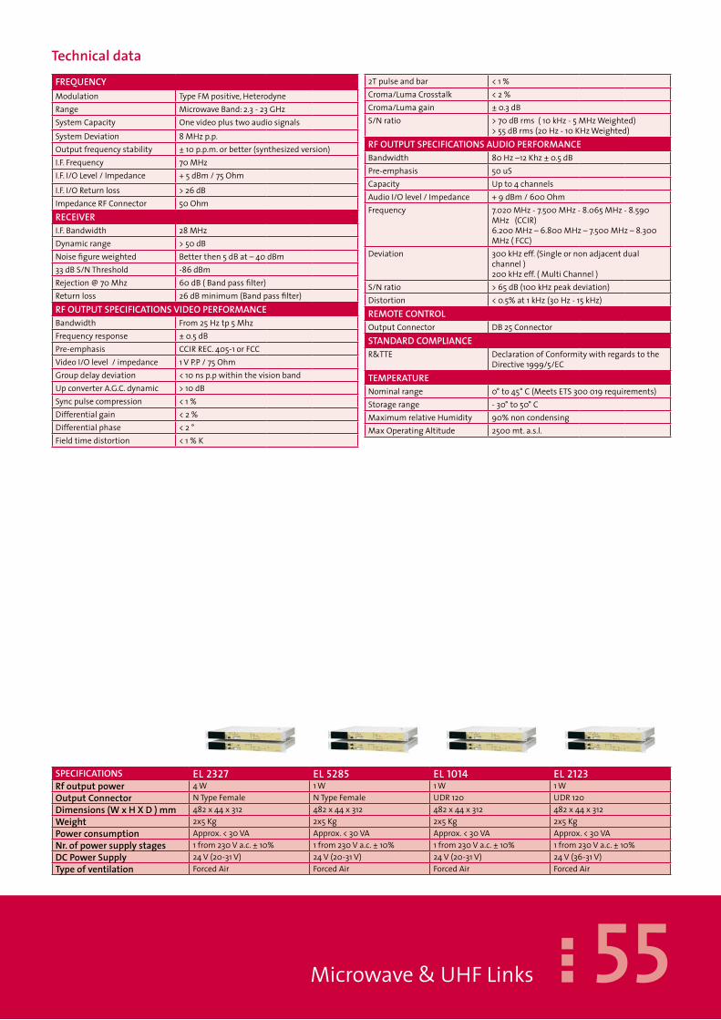
55Microwave&UHFLinks
TechnicaldataFrEQUENCYModulation TypeFMpositive,HeterodyneRange MicrowaveBand:2.3-23GHzSystemCapacity OnevideoplustwoaudiosignalsSystemDeviation 8MHzp.p.Outputfrequencystability ±10p.p.m.orbetter(synthesizedversion)I.F.Frequency 70MHzI.F.I/OLevel/Impedance +5dBm/75Ohm
I.F.I/OReturnloss >26dBImpedanceRFConnector 50OhmrECEIVErI.F.Bandwidth 28MHzDynamicrange >50dBNoisefigureweighted Betterthen5dBat–40dBm33dBS/NThreshold -86dBmRejection@70Mhz 60dB(Bandpassfilter)Returnloss 26dBminimum(Bandpassfilter)rFOUTPUTSPECIFICATIONSVIDEOPErFOrMANCEBandwidth From25Hztp5MhzFrequencyresponse ±0.5dBPre-emphasis CCIRREC.405-1orFCCVideoI/Olevel/impedance 1VP.P/75OhmGroupdelaydeviation <10nsp.pwithinthevisionbandUpconverterA.G.C.dynamic >10dBSyncpulsecompression <1%Differentialgain <2%Differentialphase <2°Fieldtimedistortion <1%K
2Tpulseandbar <1%Croma/LumaCrosstalk <2%Croma/Lumagain ±0.3dBS/Nratio >70dBrms(10kHz-5MHzWeighted)
>55dBrms(20Hz-10KHzWeighted)rFOUTPUTSPECIFICATIONSAUDIOPErFOrMANCEBandwidth 80Hz–12Khz±0.5dBPre-emphasis 50uSCapacity Upto4channelsAudioI/Olevel/Impedance +9dBm/600OhmFrequency 7.020MHz-7.500MHz-8.065MHz-8.590
MHz(CCIR)6.200MHz–6.800MHz–7.500MHz–8.300MHz(FCC)
Deviation 300kHzeff.(Singleornonadjacentdualchannel)200kHzeff.(MultiChannel)
S/Nratio >65dB(100kHzpeakdeviation)Distortion <0.5%at1kHz(30Hz-15kHz)rEMOTECONTrOLOutputConnector DB25ConnectorSTANDArDCOMPLIANCER&TTE DeclarationofConformitywithregardstothe
Directive1999/5/ECTEMPErATUrENominalrange 0°to45°C(MeetsETS300019requirements)Storagerange -30°to50°CMaximumrelativeHumidity 90%noncondensingMaxOperatingAltitude 2500mt.a.s.l.
SPECIFICATIONS EL 2327 EL 5285 EL �0�4 EL 2�23rfoutputpower 4W 1W 1W 1WOutputConnector NTypeFemale NTypeFemale UDR120 UDR120Dimensions(WxHXD)mm 482x44x312 482x44x312 482x44x312 482x44x312Weight 2x5Kg 2x5Kg 2x5Kg 2x5KgPowerconsumption Approx.<30VA Approx.<30VA Approx.<30VA Approx.<30VANr.ofpowersupplystages 1from230Va.c.±10% 1from230Va.c.±10% 1from230Va.c.±10% 1from230Va.c.±10%DCPowerSupply 24V(20-31V) 24V(20-31V) 24V(20-31V) 24V(36-31V)Typeofventilation ForcedAir ForcedAir ForcedAir ForcedAir

56
TVMicrowaveDigital L inkEDL 1011 – 1 WEDL 1214 – 1 WEDL 2123 – 1 W
Microwave&UHFLinks
TheELSERIESmicrowavelinksaredesignedforlongandmediumdistanceapplications,STL’s,backbones,multi-hopsystems,andotherbroadcastrequirementstodeliverwithbroadcast-qualityonevideoanduptofourhigh-qualityaudiochannels(twoareoptional)ordataflows.Theradiolinkisavailablefrom2,3to23Ghz:itismadeinasingle1-unitrackthatallowsafastandeasy
integrationwithexistingtelecommunicationsystemsinthefullrespectofthelevels,ofthemodulationsandoftheimpedance.Outputpowerupto4Wandseveralalarmstochecktheamplifierworkingconditionsareavailable.TheexcellentspectralpurityandthespecialdesignoftheconversionoscillatorsendowtheseunitswithanexcellentSignaltoNoiseratioinbothtransmissionandreception.
Code Model Description
F88�.02 EDL �0��-30 1WDigitalLink-16Channels,freq.10.3-10.7Ghz(TSASIin/out)
F88�.03 EDL �2�4-30 1WDigitalLink-16Channels,freq.12-14Ghz(TSASIin/out)
F88�.04 EDL 2�23-30 1WDigitalLink-16Channels,freq.21,2-23,6Ghz(TSASIin/out)
available Options ExternalHead–Encoder&DecoderMPEG2
Theradiolinksarecomposedbytwounits;anindoorunit SHF (IDUSHF) (optionally outdoor unit ODU inaerialhead)suppliedinasingle1-unitrackcontainingthe RF Transmitter (or RF Receiver) and a secondindoorunitLF(IDU-LF)suppliedinasingle1-unitrackcontaining mo/demodulator (QPSK or 16QAM MO/DEM)andco/decoder(MPEG2CO/DEC+MUX).On the front panel, a colour display provides theinformation about the functions of each board; thevideosignalsininputandoutputtoCODECMPEG2canbeeasilycheckedout.
Thepowersupplystagecanreceiveeitheralternateordirect voltage (even simultaneously); furthermore, itcanberemovedcompletelyfromitslocationtoalloweasyandquickmaintenance.The program of the function can be realized eitherlocally by the keyboard, or remotely bymeans of aninterface Ethernet 10 /100 base T which allows aremoteconnectionalsothroughtheweb.TwootherserialinterfacesRS232andsixrelècontactscompletetheinterfaces.

57
SPECIFICATIONS EDL �04 EDL �2�4 EDL 2�23rfoutputpower 1W 1W 1WOutputConnector NTypeFemale UDR120 UDR120Dimensions(WxHXD)mm 482x44x312 482x44x312 482x44x312Weight 2x5Kg 2x5Kg 2x5KgPowerconsumption Approx.<30VA Approx.<30VA Approx.<30VANr.ofpowersupplystages 1from230Va.c.±10% 1from230Va.c.±10% 1from230Va.c.±10%DCPowerSupply 24V(20-31V) 24V(20-31V) 24V(36-31V)Typeofventilation ForcedAir ForcedAir ForcedAir
Microwave&UHFLinks
TechnicaldataFrEQUENCYModulation TypeQPSK,16QAMRange MicrowaveBand:2.3-23GHzSystemCapacity SystemCapacityASI/E3G703(withoptional
de/coderonevideoplustwoaudiosignals)Outputfrequencystability ±10p.p.m.orbetter(synthesizedversion)I.F.Frequency 70MHz+/-5KHzI.F.I/OLevel/Impedance From-25to0dBminstep0,1dBm/75Ohm
BNCconnectorI.F.I/OReturnloss >26dB
ImpedanceRFConnector 50OhmrECEIVErI.F.Bandwidth 1.75to28MHz(softwareselectable)Dynamicrange >50dBNoisefigureweighted Betterthen5dBat–40dBm33dBS/NThreshold -86dBmRejection@70Mhz 60dB(Bandpassfilter)Returnloss 26dBminimum(Bandpassfilter)QPSKDE/MODULATOr-16QAMDE/MODULATOrMode QPSK-ETS300421(DVB-S)16QAM-ETS301
210FEC(coderate) Viterbi1/2,2/3, ¾,5/6,7/8selectableOutercode ReedSolomon(188204)Payload From3to45Mbits/son500Kb/sstepsSelectablerolloff 0,15–0,55in0,05stepsDatascrambling X15+X14+1
DE/CODErMPEg2(OPTIONAL)VideoInput AnaloguePALcomposite,1Vpp75Ohm,BNC
connectorVideoencodingstandards ISO/IEC13818-2MP@ML(MPEG-24:2:0)PicturetypeI,P,B Horizontal:upto720pixelin32pixelsteps
VerticalPAL:upto576pixelin32pixelstepsSupportedresolution FullD1,¾D1.2/3D1,HD1,SIFAudioinput Analoguetwochannel,0dBm600Ohm,BNC
connectorAudioencodingstandards ISO/IEC11172-3(MPEG-1audio)layer¾
compliantSamplingfrequency 32KHz,44,1KHz,48KHzBitrate Video0,8–14Mb/sAudiomax384kb/sStreamtype TransportStreamonASIinterfaceStreammultiplexingstandards ISO/IEC13818-1(MPEG-2)PATtableSystemBitrate Upto45Mb/son100KbitstepsrEMOTECONTrOLOutputConnector ParallelRemotesignalsandcontrolswith
floatingcontactsEthernetinterface ConnectorRJ46TCP/IPWebserverviaEthernet
10/100baseTSTANDArDCOMPLIANCER&TTE DeclarationofConformitywithregardstothe
Directive1999/5/ECTEMPErATUrENominalrange 0°to45°C(MeetsETS300019requirements)Storagerange -30°to50°CMaximumrelativeHumidity 90%noncondensingMaxOperatingAltitude 2500mt.a.s.l.

58
TVMobile MicrowaveAnalog&Digital L inkEML - EMDL
Microwave&UHFLinks
TheEMLSERIESmobilemicrowavelinksaredesignedforlongandmediumdistanceapplications,STL’s,backbones,multi-hopsystems,andotherbroadcastrequirementstodeliverwithbroadcast-qualityonevideoanduptofourhigh-qualityaudiochannels(twoareoptional)ordataflows.Theselinksprovideoutstandingqualityandreliabilitytogetherwitheaseofinstallationandfriendlyuse,especiallybymeansofthefastmechanicalassemblysystem.TheEMLSeriesmicrowavelinksareavailableindifferentfrequencyrangesandareequippedwithsynthesizedoscillatorswhichallowchangesoftheoperationalchannelbothfromtheoutdoorRFheadandfromtheindoorconsole.TheEMLSerieslinksareusedforanalogueapplicationsordigitalDVB-Tapplication(EMDLSeries).Tripods are fundamental accessories in the mobileradiolinkssincetheyplayabasicroleinthealignmentoperationbetweentwoparabolicreflectors.To avoid prejudice to the alignment stability, ourstandard tripods are very stable devices and have agreatcapacityofabsorbingvibrations.Thankstotheirpatenteddesign, they canbequickly adapted to anykindofgrounds.As an option, the EML Series mobile links may beprovidedwithaprofessionaltypeofTripodsandasetof special Trunks with wheels and handles for theireasytransportationandhandling.
Code Model Description
F881.01 EMDL1214-30 1WMobileLink-16Channels,freq.12-14Ghz
available Options OutdoorHead–MPEG2Encoder&Decoder

59Microwave&UHFLinks
TheoutdoorreceivingandtransmittingRFunitsareplacedinawaterproofmechanicalcase.To facilitate the system’s tracking operations, the outputpower leveland the inputRF levelareavailablebymeansofanexternalmeterdevice.TheIFmonitoringconnectorandasocket for the“Intercom”circuitbetween the indoor consoleandtheoutdoorunitarealsoavailable
TechnicaldataStructureofthetripod SingleflowingtubeMinimumoperativeelevationfromearth
780mm
Maximumoperativeelevationfromearth
1580mm
Tripodweight 8,0KgLegdiameter 40mmTerminaldiameter 35mmMaximumload 30,0Kg
Heightwhenclosed 940mmLegMaterial AluminiumTerminallegMaterial ChromiumplatedsteelFoot Reversiblewithconicaltiporantivibration
rubberfoot.Pulling AdjustableallumiumSpecialoptions Antisliderubberhandles

60
FMUHFStudioL inks– FMreceiversUTX-15M UTX-15/SURX-15M URX-15/SRX-12 RX-12/S
FMStudioLinks
ThesenewUHFlinksaredesignedforlongandmediumdistanceapplications,STL’s,backbones,multi-hopsystemsandotherbroadcastrequirements,wheneverthepurposeistodeliverwithbroadcast-qualityuptofourhigh-qualityaudiochannels(twoareoptional)ordataflows.
Theradiolinkisavailablefrom180Mhzupto450MHZ:itismadeinasingle2-unitrackthatpermitsafastandeasyintegrationwithexistingtelecommunicationsystems,withoutanydegradationsaboutthelevels,themodulationsandtheimpedance
Code Model Description
F89� UTX-�5/M 15WMono/MPXUHFTransmitter180-450MHz
F892 UTX-�5/S 15WStereo/UHFTransmitter180-450MHz
F889 URX-�5/M UHFMono/MPXReceiver180-450MHz
F890 URX-�5/S UHFStereoReceiver180-450MHz
F887 RX-�2 FMMono/MPXReceiver87.5-108MHz
F887.0� Rx-�2/S FMMono/MPX/StereoReceiver87.5-108MHz
The output power is continuously adjustable up to15W;severalalarmstokeepundercontroltheworkingconditionsoftheamplifierareavailable.Theexcellentspectralpurityandthespecialdesignoftheconversionoscillatorsendowtheseequipmentwith
anexcellentSignaltoNoiseratio,bothintransmissionandreceptionstage.
Both Transmitter and Receiver are agile: this meansfriendlyuseforinstallationandreadjustments

6�
SPECIFICATIONS UTX�5 URX�5 RX�2rfoutputpower 15WOutputConnector NTypeFemale50Ohm NTypeFemale NTypeFemale50OhmDimensions(WxHXD)mm 482x88x500 482x884x500 482x88x500Weight 12Kg 12Kg 12KgPowerconsumption Approx.<130VA Approx.<90VA Approx.<90VANr.ofpowersupply 1from230Va.c.±10% 1from230Va.c.±10% 1from230Va.c.±10%DCPowerSupply 24V(18-26V) 24V(18-26V) 24V(18-26V)Cooling ForcedAir ForcedAir ForcedAir
FMStudioLinks
TechnicaldataFrEQUENCYModulation solidstatedirectFMfrequencysynthesised
crystalref.thermalcompensatedRange 180-450MHZ(tx_range50Mhzbandwidth;
rx_range5MHZ/for50MHZbandwidthtuningfilterisrequired)
SystemCapacity 1stereoprogramor1monoprogramandonesubcarrier(SCA)Betterthan2pp
Setting Directlydigitallyprogrammableonthefrontpanelin100kHzsteps
FinefrequencyAdjustment InternationalmultiturntrimmerrFOUTPUTSPECIFICATIONSVIDEOPErFOrMANCEHarmonicssuppression <-80dBcSpuriousEmission <-80dBcResidualAsynchronyAM >60dBWeighedResidualSynchronyAM >60dBWeighedS/NRATIO(weighted) >70dB(referredto±75KHz)Distortion 0.05%orlessfor75kHzFMdeviationProbe BNCconnectorRF0dBm;BNCconnectorLF12
dBmAUDIOSPECIFICATIONSMono/MPXImpedance 600Ohmbal.or10KOhmunbal.,XLRfemale
ConnectorSCAImpedance 10KOhmunbal.,BNCConnectorMono/MPXSCALevel From0to+12dBmLeft,andRightImpedance 600Ohmbal.or10KOhmunbal,XLRfemale
ConnectorLeft,RightLevel From–6to+12dBmStereoSeparation >60dB(40Hzto15KHz)THD <0,15%From30Hzto15KHzwithde-emphasisrECEIVErSPECIFICATIONSSelectivityStatic 3dB@±150KHz;60dB@±450KHz;
80dB@±600KHzSelectivityDynamic ±300KHz@+5dB;±400KHz@+38dB;
±500KHz@+40dBSensitivityMono(deviation±75KHz)
15mV(S/N=60dBwithbandwidth=30÷15KHz)
SensitivityStereo(deviation±75KHz)
150mV(S/N=60dBwithbandwidth=30÷15KHzdecoded,de-emphasis)
DESIgNDATAPre&Deemphasis Flator75or50μsAmplituderesponseTX (Mono)±0,15dB(from30Hzto15KHz)-40dB
from19kHzto100kHz(MPX)±0,1dB(from40Hzto100KHz)(SCA)1dB(from20KHzto100KHz)
AudiofrequencyresponseRX (Mono)<0,15dB(from30Hzto53kHz);<-45dB(from19kHzto100kHz)(MPX)<0,2dB(from30Hzto53kHz)<1dB(from53Hzto75kHz)<3dB(from75kHzto100kHz)>40dB(from120kHzto1MHz)
DisplayMeter Frequency,poweroutput,voltage,temperature,lock,inputlevelmeter,inputlevelset,pre-emphasisvalue,pre-emphasisset,carrierenable,temperaturealarmset,-3dBpowerdownalarmset
Protections AlarmFrequencyprogrammingerrorLocaloscillatorlockedinHeatsinktemperatureexceedsthatsetRFoutputpowerbelow2,5W(TXversion)RFoutputpowerbelowsquelchthreshold(RXversion)Powersupplyvoltageofamoduleoutsidethepermittedrange
rEMOTECONTrOLOutputConnector DB9connectors(command-CD:transmitter
power;RX:RS232signal;TX:RS232signal;ALL1&ALL2:alarmoutputsignal;GND:earth;
STANDArDSCOMPLIANCERadiospectrum RTTEEMC ETS449,ETS-339,ETS-384,CCIR-450,CCIR-412,
CCIR-559,CCIR-468Safety EN60950-EN60215R&TTE DeclarationofConformitywithregardstothe
Directive1999/5/ECTEMPErATUrENominalrange 0°to45°C(MeetsETS300019requirements)Storagerange -30°to50°CMaximumrelativeHumidity 90%noncondensingMaxOperatingAltitude 2500mt.a.s.l.

62
StudioL inksMicrowaveAnalogueL inksMTL/M-P MTL/S-P MR/P MR/S-PMTL/M-UK MTL/S-UK MR2/UK
MicrowaveLinks
TheseStudioTransmitterLinksoperateonthefollowingfrequencybands:1.400–2.700GHz(EuropeanBand1.377-1.382GHz;1.429-1.434GHz;1.517-1.525GHz;1.660-1.670GHz;2.367-2.372GHz;2.468-2.483GHz.)TheMTLequipmentaresuitablefortransmittingahigh-qualitymonoorstereoaudiosignalforbroadcastingwithoutputpowerupto5W.IntheTransmittertherearenotunedcircuitsoradjustablecomponentsfortuningontotherequiredfrequency.Also,sinceallthecircuitsarewideband,
theabsenceofspuriousemissionsisassured.Thefrequencystepsofthesynthesisedoscillatorare100kHz.IntheUKversion,acirculatorensureseffectiveprotectionagainstpossibleintermodulationproductscausedbyothertransmittersfeedingthesamedish,andalow-lossbandpassfilterwhichrestrictsharmonicemissionstothelevelsincompliancewiththestrictestcurrentstandards.Itisalsopossibletopowertheequipmentbyusinganexternal24Vdcbattery.
Code Model Description
F445.04 MTL/M-P 4WMono/MPXMicrowaveTransmitterwithOutputFilter
F445.05 MTL/M-UK 3,5WMono/MPXMicrowaveTransmitterwithCirculator
F445.07 MTL/S-P 4WStereoMicrowaveTransmitterwithOutputFilter
F445.08 MTL/S-UK 3,5WStereoMicrowaveTransmitterwithCirculator
F444.04 MR/P MicrowaveMono/MPXReceiver
F444.05 MR2/UK MicrowaveMono/MPXReceiver1377-1382;1429-1434MHz
F444.07 MR/S-P MicrowaveStereoReceiver
available Options Stereocoder&decoder-Circulator-Otherfrequencyonrequestintherangefrom1400to2700MHz
-Samesynthesisedoscillator for the transmitterandthereceiver.-Comblinebandpassfiltertoensureimage-frequencyrejectionexceeding60dB.-Highsensitivityinmonoisaround10mVper60dBofS/NRatio.
- Low phase and frequency distortion of the outputbase-band are ensured by the AGC, compensatedfilters, digital-pulse frequency demodulator,amplitudeandphase equaliser andan elliptic low-passfilterwithcut-offof100kHz.

63
SPECIFICATIONS MTL P MTL UK MR P MR UKrfoutputpower 5W 5WOutputConnector NTypeFemale50Ohm NTypeFemale NTypeFemale50Ohm NTypeFemaleDimensions(WxHXD)mm 482x88x500 482x884x500 482x88x500 482x884x500Weight 12Kg 12Kg 12Kg 12KgPowerconsumption Approx.<130VA Approx.<130VA Approx.<130VA Approx.<130VANr.ofpowersupply 1from230Va.c.±10% 1from230Va.c.±10% 1from230Va.c.±10% 1from230Va.c.±10%DCPowerSupply 24V(18-26V) 24V(18-26V) 24V(18-26V) 24V(18-26V)Cooling ForcedAir ForcedAir ForcedAir ForcedAir
MicrowaveLinks
TechnicaldataFrEQUENCYModulation solidstatedirectFMfrequencysynthesised
crystalref.thermalcompensatedRange PVersion:1517÷1525;1650÷1680;2367÷2372;
2468÷2435MHzUKVersion:1429÷1434;1377÷1382MHz
SystemCapacity 1stereoprogramor1monoprogramandonesubcarrier(SCA)
Outputfrequencystability Betterthan2ppmSetting Directlydigitallyprogrammableonthefront
panelin100kHzstepsFinefrequencyAdjustment InternationalmultiturntrimmerrFOUTPUTSPECIFICATIONSVIDEOPErFOrMANCEHarmonicssuppression <-80dBcSpuriousEmission <-80dBcResidualAsynchronyAM >60dBWeighedResidualSynchronyAM >60dBWeighedS/NRATIO(weighted) >70dB(referredto±75KHz)Distortion 0.05%orlessfor75kHzFMdeviationProbe BNCconnectorRF0dBm;BNCconnectorLF12
dBmAUDIOSPECIFICATIONSMono/MPXImpedance 600Ohmbal.or10KOhmunbal.,XLRfemale
ConnectorSCAImpedance 10KOhmunbal.,BNCConnectorMono/MPXSCALevel From0to+12dBmLeft,andRightImpedance 600Ohmbal.or10KOhmunbal,XLRfemale
ConnectorLeft,RightLevel From–6to+12dBmStereoSeparation >60dB(40Hzto15KHz)THD <0,15%From30Hzto15KHzwithde-emphasisrECEIVErSPECIFICATIONSSelectivityStatic 3dB@±150KHz;60dB@±450KHz;
80dB@±600KHzSelectivityDynamic ±300KHz@+5dB;±400KHz@+38dB;
±500KHz@+40dBSensitivityMono(deviation±75KHz)
15mV(S/N=60dBwithbandwidth=30÷15KHz)
SensitivityStereo(deviation±75KHz)
150mV(S/N=60dBwithbandwidth=30÷15KHzdecoded,de-emphasis)
DESIgNDATAPre&Deemphasis Flator75or50μsAmplituderesponseTX (Mono)±0,15dB(from30Hzto15KHz)-40dB
from19kHzto100kHz(MPX)±0,1dB(from40Hzto100KHz)(SCA)1dB(from20KHzto100KHz)
AudiofrequencyresponseRX (Mono)<0,15dB(from30Hzto53kHz);<-45dB(from19kHzto100kHz)(MPX)<0,2dB(from30Hzto53kHz)<1dB(from53Hzto75kHz)<3dB(from75kHzto100kHz)>40(from120kHzto1MHz)
DisplayMeter Frequency,poweroutput,voltage,temperature,lock,inputlevelmeter,inputlevelset,pre-emphasisvalue,pre-emphasisset,carrierenable,temperaturealarmset,-3dBpowerdownalarmset
Protections AlarmFrequencyprogrammingerrorLocaloscillatorlockedinHeatsinktemperatureexceedsthatsetRFoutputpowerbelow2,5W(TXversion)RFoutputpowerbelowsquelchthreshold(RXversion)Powersupplyvoltageofamoduleoutsidethepermittedrange
rEMOTECONTrOLOutputConnector DB9connectors(command-CD:transmitter
power;RX:RS232signal;TX:RS232signal;ALL1&ALL2:alarmoutputsignal;GND:earth;
STANDArDSCOMPLIANCERadiospectrum ETSI300-384EMC ETS449,ETS-339,ETS-384,CCIR-450,CCIR-412,
CCIR-559,CCIR-468Safety EN60950-EN60215R&TTE DeclarationofConformitywithregardstothe
Directive1999/5/ECTEMPErATUrENominalrange 0°to45°C(MeetsETS300019requirements)Storagerange -30°to50°CMaximumrelativeHumidity 90%noncondensingMaxOperatingAltitude 2500mt.a.s.l.

64
Automatic ChangeOver UnitACUACU-S
TheACUmodelisauniversalandflexibleautomaticchange-overunitdesignedforcontrollingFMradioandtelevisiontransmittersorrepeaters.ACUincludesaBasebandandRFinternalswitch.Itcanalsocontrolanexternalhighpowercoaxialrelay.IncaseofbreakdownofthemainRFsignal,theequipmentoperatesthesubsequentswitch-overtotheauxiliarysource,thusensuringcontinuityofservice.Theinternalcoaxialrelayallowsswitch-overofRFsignalsofupto350Waveragepowerupto1GHz,and150Wupto3GHz.BymeansofthededicatedDB-25connectorlocatedintherearpaneloftheunit,itcanbematchedwithanytypeofexternalcoaxialrelaytocontrolanyhigh-powerinstallations.
Theunit,whichis100%microprocessor-controlled,allowsthesoftware-operatedconfigurationofalloperatingparameters,suchaslowpowerthreshold,waitingandswitchingtime.Thegraphicdisplaymakesitpossibletochecktheparametersettingsandtheoperationalstatusofthesystem.Automaticoperationcanbedeactivatedfromthefrontpanelinordertoallowthemanualcontrolofswitching.Allbase-bandroutingismadebymeansoffullypassivebistablecircuitry,inordertograntthesignalcontinuityevenincasethechangeoverunitgetsdamaged.Theunitfeaturesadualindependentmainspowersystemand,asastandard,itisequippedwithlowvoltageDCinputforbatterysuppliedsystems.
Code Model Description
F860.02 aCU AutomaticchangeoverunitforFM&TVEquipment
F860 aCU-S AutomaticchangeoverunitforFM&TVEquip.withSwitch350W
available Options InternalDCInput24Vor48V
TechnicaldataVideoA,VideoB BNC,75OhmfullypassiveroutingAudiostereo LeftA(main),LeftB(aux),RightA(main),Right
B(aux),AudioConnector standardXLRfullypassiveroutingOutputConnector NTypeFemale50OhmInputSensitivity -30dBmnominal±20dBOperatingfrequency 1GHzAverageoutputpower 350WInsertionloss 0.15dB 2Ghz 3GhzV.S.W.R 1.15 250W 150WIsolationbetweenchannels 85dB 0.2dB 0.25dBParallelport 25pinsub-Dconnector 1.20 1.25
UnitAandUnitB FullyisolatedINPUTSandOUTPUTS80dB75dBCanBUS(futureoption) 9pinsub-DconnectorSerialRS232/RS485 9pinsub-Dconnector(softwareselectableby
user)EthernetTCP/IP RJ45(optional)Temperatureoperatingrange 0°to45°C(MeetsETS300019requirements)MaximumrelativeHumidity 90%noncondensingDimensions(WxHXD)mm 482x44x450Weight 5KgPowerconsumption Approx.<50VANrofpowersupplyboards 2from230Va.c.±20%DCPowerSupply 24Vor48Vfloating
Accessories&Systems

65Accessories&Systems
Automatic ChangeOver SystemACS (N + 1 system)
TheACSmodelisauniversalandflexibleautomaticchange-overunitdesignedforcontrollingFMradioandtelevisiontransmittersorrepeaters.Incaseofdamageofoneofthemainequipment,theACSautomaticallyswitchestothereserveequipment.Theequipmentcanbeusedintheapplicationsforactiveandpassivereservesystems,pre-andfinalstagereserve,(n+1)-systemsandforthecontrolofantennaselectorswitches.TheACSisdesignedtocontroluptosixserviceequipmentsandonereserveaccordingto(n+1)-systems.ThegeneralswitchovercriteriaaswellasthedelaytimebetweenmissingRFsignalandswitchover,andthepriorityofthesurvivetransmitter,arefreelyselectable.Allprogramspecificsettingsoftheservicetransmitterareeffectiveincaseoftheswitchingovertothereserveequipment.Furthermore,manualswitchoverandoperationofthe
eachequipmentviatheACSarepossible.BymeansofthededicatedDB-25connectorlocatedintherearpanel,theequipmentcanbeconnectedwithanytypeofexternalcoaxialrelaystocontrolhigh-powerinstallations.Theunit,whichis100%microprocessor-controlled,allowsthesoftware-operatedconfigurationofalloperatingparameters,suchaslowpowerthreshold,waitingandswitchingtime.ThegraphicdisplayisaTFT6”colourVGAandmakesitpossibletochecktheparametersettingsandtheoperationalstatusofthesystem.Theestablishedoperatingfiguresandthestatusofthetransmittersandantennas,arerespectivelysymbolicallyrepresentedinthegraphicdisplay.Alltheconnectionstothecomponentsofthetransmittersystemarearrangedintherearpartoftheunit.TheunitfeaturesadualindependentmainssystemandoptionallyincludesalowvoltageDCinputforbatterysuppliedsystems.
Code Model Description
F860.02 aCS AutomaticchangeoverSystemupto6FM&TVEquipment
available Options InternalDCInput24Vor48V
TechnicaldataControls uptosixservicetransmittersandonereserve
transmitterina(n+1)-systemFastoverview operatingstatuswithLED’sonthefrontpanel
Statusoverview TFT6”VGAgraphiccolourdisplaySerialRS232/RS485 9pinsub-Dconnector(softwareselectableby
user)EthernetTCP/IP RJ45(optional)
Temperatureoperatingrange 0°to45°C(MeetsETS300019requirements)MaximumrelativeHumidity 90%noncondensingDimensions(WxHXD)mm 482x132x450Weight 6KgPowerconsumption Approx.<100VANrofpowersupplyboards 2from230Va.c.±20%DCPowerSupply 24Vor48Vfloating(optional)

66
AnalogueTVTransmittersE 50-TU – 50 WEK 150-TU –150 WEK 200-TU – 200 W Basically,thegeneraldesignofourTelevisiontransmittersincludesfiveplug-inmoduleswithoutputpowerupto200Wsolidstate.Thedirectionalcoupler,theoutputfilterandtheswitchingpowersupplymodulearebuilt-instagesinanyequipment.ThetransmittersareavailabletooperateonanybandsandincompliancewithseveralTVstandards.Togreatlysimplifytheconversiontodigital
technology,theTVmodulatorisanexternalunit.Themodulatorcanoperateasafinalstagedirectlyconnectedtoaradiatingsystemorasadriverinanindependentpoweramplifier.Inanyequipment,RJ-45,RS-485andparallelinterfaceconnectorsareavailableforremotecontrolmonitoring.
Code Model Description
F842.0� E �0-TU 10WUHFTransmitterwithoutputfilter
F842 E 50-TU 50WUHFTransmitterwithoutputfilter
F844 EK �50-TU 150WUHFTransmitterCOMPACTwithoutputfilter
F878 EK 200-TU 200WUHFTransmitterCOMPACTwithoutputfilter
available Options PrecisionTCXO
TechnicaldataSPECIFICATIONS E�0-TU E50-TU EK�50-TU EK200-TUrfoutputpower 10Wps 50Wps 150Wps 200WpsOutputConnector NTypeFemale NTypeFemale NTypeFemale NTypeFemaleDimensions(WxHXD)mm 482x176x450 482x176x450 482x176x450 482x176(+44)x450Weight 20Kg 20Kg 22Kg 25KgPowerconsumption Approx.<140VA Approx.<370VA Approx.<700VA Approx.<850VANr.ofpowersupplyboards 1from230Va.c.±15% 1from230Va.c.±20% 1from230Va.c.±20% 1from230Va.c.±15%DCPowerSupply 48V(36-60V) 48V(36-60V) 48V(36-60V) 48V(36-60V)Numberoffans 2blowers,24Vdc 2blowers,24Vdc 2blowers,24Vdc 2blowers,24Vdc
Accessories&Systems

67Accessories&Systems
AnalogueTVTransmittersE 300-TU – 300 WE 500-TU – 500 WE 1000-TU –1 KW Basically,thegeneraldesignofourTelevisiontransmittersincludesfiveplug-inmoduleswithoutputpowerupto1KWsolidstate.Thedirectionalcoupler,theoutputfilterandtheswitchingpowersupplymodulearebuilt-instagesinanyequipment.ThetransmittersareavailabletooperateonanybandsandincompliancewithseveralTVstandards.Togreatlysimplifytheconversiontodigitaltechnology,theTVmodulatorisanexternalunit.Themodulatorcanoperateasafinalstagedirectlyconnectedtoaradiatingsystemorasadriverofanindependentpoweramplifier.InanyequipmentRJ45,RS485andparallelinterfaceconnectorfortheremotecontrolmonitoring
Code Model Description
F848.0� E 300-TU 300WUHFTransmitterwithoutputfilter(20Ucabinetincl.)
F848 E 500-TU 500WUHFTransmitterwithoutputfilter(20Ucabinetincl.)
F896 E �000-TU 1000WUHFTransmitterwithoutputfilter(20Ucabinetincl.)
available Options PrecisionTCXO
TechnicaldataSPECIFICATIONS E300-TU E500-TU E�000-TUrfoutputpower 300Wp.s. 500Wp.s. 100Wp.s.OutputConnector 7/16TypeFemale 7/16TypeFemale 7/16TypeFemaleDimensions(WxHXD)mm 600x800x660 600x800x660 600x800x660Weight 120Kg 120Kg 150KgPowerconsumption Approx.<140VA Approx.<370VA Approx.<700VANr.ofpowersupplyboards 3from230Va.c.±15% 4from230Va.c.±15% 5from230Va.c.±20%DCPowerSupply 48V(36-60V) 48V(36-60V) 48V(36-60V)Numberoffans 4blowers 4blowers 4blowers

68
Digital TVTransmittersE 125-DU – 125 WE 250-DU – 250 W TheEDSERIEStelevisiontransmittersaredesignedwiththelateststateofthearttechnologyandarecomposedbytheDVB-TDriver,thesolidstatepoweramplifierandtheoutputfilter.Alltheequipmentareassembledina19”cabinetandcandeliverupto250Woutputpower.TheEDSERIEStransmittersuseruggedandreliablecomponentsandultimatecircuitdesign.Theequipmentcanbesuitableforunattendedoperation.Inthedesign,aparticularattentionhasbeengiventogreatlyimproveredundancyineachstage/moduleintheRFchainaswellasintheoveralltransmitterconfiguration.ThelatestRFpowerFETTransistorusedintheEDSERIESassuressuperiortechnicalperformanceindigitalapplications.TheseequipmentareavailabletooperateonallbandsandaredesignedtoreceiveDVB-TandDVB-HTransportStreamsignals.Configurationsasdualdriveorfullredundancy1+1areavailableonrequest.ThetransmittersareequippedwithRJ45,RS485andparallelinterfaceconnectorfortheremotecontrolmonitoring.
Code Model Description
F873 E �25-DU 125WrmsUHFDVB-T/HDigitalTransmitter-(20Ucab.incl.)
F875 E 250-DU 250WrmsUHFDVB-T/HDigitalTransmitter-(20Ucab.incl.)
available Options 6MHzBandwith-5MHzBandwith-RF Agileconverter–GPSReceiver- WEBBrowser-SNMPclient-PrecisionTCXO(0,01ppm).
TechnicaldataSPECIFICATIONS E�25-DU E250-DUrfoutputpower 125Wps 250WpsOutputConnector 7/16TypeFemale 7/16TypeFemalerange UHF(470-860MHz) UHF(470-860MHz)Dimensions(WxHXD)mm 600x800x660 600x800x660Weight 110Kg 120KgPowerconsumption Approx.<1300VA Approx.<2300VAPowersupplyreq. from230Va.c.±15% from230Va.c.±15%Nr.ofpowersupplyboards 1 2Numberoffans 2+1blowers 2+2blowers
Accessories&Systems

69Accessories&Systems
Digital TVTransmitterE 500-DU – 500 W
TheEDSERIEStelevisiontransmittersaredesignedwiththelateststateofthearttechnologyandarecomposedbytheDVB-TDriver,thesolidstatepoweramplifierandtheoutputfilter.Alltheequipmentareassembledina19”cabinetandcandeliverupto250Woutputpower.TheEDSERIEStransmittersuseruggedandreliablecomponentsandultimatecircuitdesign.Theequipmentcanbesuitableforunattendedoperation.Inthedesign,aparticularattentionhasbeengiventogreatlyimproveredundancyineachstage/moduleintheRFchainaswellasintheoveralltransmitterconfiguration.ThelatestRFpowerFETTransistorusedintheEDSERIESassuressuperiortechnicalperformanceindigitalapplications.TheseequipmentareavailabletooperateonallbandsandaredesignedtoreceiveDVB-TandDVB-HTransportStreamsignals.Configurationsasdualdriveorfullredundancy1+1areavailableuponrequest.ThetransmittersareequippedwithRJ45,RS485andparallelinterfaceconnectorfortheremotecontrolmonitoring
Code Model Description
F874 E 500-DU 500WrmsUHFDVB-T/HDigitalTransmitter-(20Ucab.incl.)
available Options 6MHzBandwith-5MHzBandwith-RF Agileconverter–GPSReceiver- WEBBrowser-SNMPclient-PrecisionTCXO(0,01ppm).
TechnicaldataSPECIFICATIONS E500-DUrfoutputpower 500Wrms.OutputConnector 7/16TypeFemalerange UHF(470-860MHz)Dimensions(WxHXD)mm 600x800x660Weight 150KgPowerconsumption Approx.<4300VAPowersupplyreq. three-phase380Va.c.±15%Nr.ofpowersupplyboards 3Numberoffans 2+3blowers

70
Uninterruptible PowerSupplyMegaline
UPS’scanprotectsystemsagainstlightningstrikes,powerfailures,brownouts,surges,poorlyconditionedpowerfeedsandofferaneconomicalsafeguardagainstmanyformsofelectricalspikesinthefrequencyortheamplitudeoftheinputvoltage.Incaseofcriticalenvironmentwithnoproperprotectioninstalled,thesekindsofoccurrencescancausedamagetotheequipmentorcausecomponentsnottoworkorfunctionproperly.InourMEGALINEUPS’s,thedecouplingoftheoutputfromtheinputmakesitpossibletooperatetheequipmentwithawideinputvoltagerange,reducingthenumberofbatteryswitchoversandallowingoperationwithGEN-SETSandfrequencyconversion.Thankstothespecialdesignoftheinverterstagewhichisalwaysonline,theinterventiontimeisnil.Themodulararchitectureofelectronicsandbatteriesadmitsredundantconfigurations,simplifiedmaintenanceandthepossibilityoffastexpansions,toprovideyourUPSwithadditionalincreasedcapability.
Redundancyintermsofboththepowermodulesandthebatteries:rectifier,inverterandbatterychargerareallfittedoneachofthepowerboards.Operatingcontinuityisalwaysguaranteed,evenifoneofthemodulesshouldfail,withoutanyinterruptionorswitchover,thankstoparallelloadsharing(alltheboardsparticipateinthesupplyofpowertotheload).Thelevelofredundancyissetviasoftwareusingthedisplay,towarnwhenredundancy,butnotoperation,maybeendangeredbecauseofanincreaseinconsumption.AlltheoperatingdataandUPSsettingsarereadilyaccessiblebywayoftheLCDpanel.TheoperatingparameterscanbesetinUPSSetupinordertooptimisetheirapplication.ItisalsopossibletoprogrammeUPSswitchon,
switchoffandtestingwithadaily,weeklyormonthlyschedule,oroncommand.TheLCDdisplayisextremelyuserfriendly,sothattheseoperationsarealsoaccessibletothelessexperienced.Passwordprotection,however,isenvisaged.Easytoexpandinpowerandautonomythankstothefullmodularityoftheboardsandthelowvoltage(36V)batterykits,enablingthebatteryoperationtimetobecustomisedaccordingtothespecificapplication.Allthemodels,eventhesinglecabinetversionsupto5000VA,canbeeasilyconnectedtoexternalbatterycabinetswithouttheneedforanymodificationthankstothestandard,plug&play-typeconnection.
Code Model Description
F859 MEGa 2500R UPS2,5KVAMEGALINERACK(Backup30min.at80%)
available Options 1Batterychargerslotsindedicatedbatterycabinetuptp5000W
Accessories&Systems

7�
TechnicaldataBackup–50% load20Bypass Static+electromechanical-zerotransfertimeOverloadcapability(mainsmode)
150%for30sec.-200%for5sec.Withoutbypassintervention
Acousticnoise@1m 40dBASTANDArDSCOMPLIANCETypicalFeatures EN50091-3EMC EN50091-2Safety EN50091-1TEMPErATUrENominalrange 0°to40°C(MeetsETS300019requirements)MaximumrelativeHumidity From20%to80%noncondensing
Technology OnlinedualconversionInputvoltagerange 184÷264Vwith100%load-100÷264Vwith
50%loadInputfrequency 50/60Hz±2%autosensingInputcurrentTHD <3%Inputpowerfactor >0,99from20%ofloadonOUTPUTSPECIFICATIONSNominaloutputvoltage 230V±1%Nominaloutputfrequency 50/60HzsynchronizedOutputvoltageTHD <1%Batteries 3pcs12V9Ahseald,lead-acid,maintenance
freebatterieseachpowerboardBackup–80% load11
SPECIFICATIONS MEGaLInE �250 MEGaLInE 2500 MEGaLInE 3750 MEGaLInE 3750Nominalpower 1250 2500 3750 5000Activepower 875 1750 2625 3500Batteriesnumber 3 6 9 12Dimensions(WxHXD)mm 270x475x570 270x475x570 270x475x570 270x475x570Weight 23Kg 34Kg 43Kg 53KgInstalledpowerboards 1 2 3 4Availablepowerslots 3 2 1 0Installedbatterykits 1 2 3 4Availablebatteryslots 3 2 1 0
SPECIFICATIONS MEGaLInE 6250/2 MEGaLInE 7500/2 MEGaLInE 8750/2 MEGaLInE �0000/2Nominalpower 6250 7500 8750 10000Activepower 4375 5250 6125 7000Batteriesnumber 15 18 21 24Dimensions(WxHXD)mm 2x270x475x570 2x270x475x570 2x270x475x570 2x270x475x570Weight 26+58Kg 29+65Kg 31+73Kg 34+80KgInstalledpowerboards 5 6 7 8Availablepowerslots 4 3 2 1Installedbatterykits 4 5 6 7Availablebatteryslots 6 5 4 3
Accessories&Systems

72
Uninterruptible PowerSupplyTrimod
UPSescanprotectsystemsagainstlightningstrikes,powerfailures,brownouts,surges,poorlyconditionedpowerfeedsandofferaneconomicalsafeguardagainstmanyformsofelectricalspikesinthefrequencyortheamplitudeoftheinputvoltage.Incaseofcriticalenvironmentwithnoproperprotectioninstalled,thesekindsofoccurrencescancausedamagetotheequipmentorcausecomponentsnottoworkorfunctionproperly.Modularity,redundancy,scalability,versatility,efficiency,allthesametime.ThesearethereasonswhytheTRIMODlineistrulyauniqueandrevolutionaryUPS.Withitsinnovativemodularstructureandexcellentqualityofthecomponents,TRIMODguaranteesabsolutereliability.Infact,themodularsolutionappliedtotheseUPSallowsredundantconfigurationswithrespecttotheloadsothatanyfailuresofonemoduleiscompensatedbytheremainingmodules,withnodowntime.Thankstothemodularconcept,totheextremelycompactsizeandtothesimpleinstallationprocess,TRIMODcanbeup-gradedaccordingtothecustomer’srealneedsbysimplyaddingpowermodulesandbatterymodulesjustasneeded.TheenergyefficiencyofferedbyTRIMODisamongthebestonesavailableinthemarkettoday.Thismeansasignificantsaveofenergywhentheequipmentisunderoperation.Moreover,TRIMODcontributestoeliminatethecostsrelatedtotheabsorptionofreactivepowerthankstothePowerFactorCorrectionoftheinputcurrent,providinggreatpowersavingsinoperatingcostsaswellassavingsintheinstallationandequipmentcosts.Theexclusive“SmartCharger”functionensuresthatbatteryoperatesunderequalisedandbalancedconditionsatanytime,grantingalongerworkinglifeandprovidingthebenefitsofgreatsavingsinmaintenancecosts.TRIMODiseasilytransportablebyasinglepersoninaregularvan,movabletoitsinstallingposition
andinstallableinsidesheltersorbuildings,withthemaximumofeaseandinaminimumoftime.TRIMODmeetstheneedsofawidevarietyofapplicationsdemandingenhancedversatilitytobeadapttothevarioustypesofelectricalsystems.Theunitisavailableforsingle-orthree-phaseinput,single-orthree-phaseoutputwiththepossibilityofadaptingtheoutputvoltageandfrequencyparameters,withinsulationorpassingneutral:TRIMODreallycoversalltypesofapplication.
Code Model Description
F859.05 TRIMOD 8 UPS8KVATRIMOD
available Options Isolatingtransformer
Accessories&Systems

73
TechnicaldataEFFICIENCYAC/AC(online) 93%maxAC/AC(EcoMode) 98%DC/AC(onbatteries) 93%maxrEMOTECONTrOLOutputConnector TwoRS232serialports(onstandardcanonDB9
connectors)Onelogiclevelport(oncanonDB9maleconnector)Fourdrycontactoutputs(userselectableNCorNOrelaycontacts)
UserInterface Back-litdisplaywithcolourstatusindicatorandmulti-functionbuttonsforrealtimemonitoringofremainingruntimeandUPSworkingstatus
STANDArDSCOMPLIANCETypicalFeatures EN62040-3EMC EN50091-2Safety EN62040-1-1ProtectionLevel IP20TEMPErATUrENominalrange 0°to40°C(MeetsETS300019requirements)MaximumrelativeHumidity From20%to80%noncondensingCoolingSystem Fanassisted,independentoneachpower
module.Smartelectroniccontrolbasedontheambienttemperatureandtheloadpercentage
Technology OnlinedualconversionInput/OutputConfiguration 1/1,3/1,3/3,1/3(userselectableduring
installation)3/3Inputvoltagerange 230+15%-20%/400+15%-20%(neutralline
isneeded)Inputfrequency 50/60Hz±2%auto-sensingInputcurrentTHD <5%Inputpowerfactor >0,99OUTPUTSPECIFICATIONSNominaloutputvoltage 230±1%/400±1%Nominaloutputfrequency 50/60HzsynchronizedOutputvoltageTHD <1%Batteries 3pcs12V9Ahsealed,lead-acid,maintenance
freebatterieseachpowerboardBackup–80% load11
Backup–50% load20Bypass Staticandelectromechanical(independenton
eachpowermodule)Overloadcapability(mainsmode)
150%for30sec.-200%for5sec.Withoutbypassintervention
CrestFactor 3.5Acousticnoise@1m 42÷46dBA
SPECIFICATIONS TRIMOD 8 TRIMOD �0 TRIMOD �6 TRIMOD 20 TRIMOD 30Nominalpower 8000 10000 16000 20000 30000Activepower 6400 8000 12800 16000 24000InstalledPowerModules 3 3 6 6 9Dimensions(WxHXD)mm 414x1345x628 414x1345x628 414x1345x628 414x1345x628 2x414x1345x628Weight 110Kgs 110Kgs 130Kgs 130Kgs 1540+70Kgs
Accessories&Systems
in400V
out230V
in230V
out400V
in230V
out230V
out400V
in400V
›Three-phaseinput/Single-phaseoutput›Three-phaseinput/Three-phaseoutput›Single-phaseinput/Single-phaseoutput›Single-phaseinput/Three-phaseoutput
OUT
IN
BY-PASS
BY-PASS
BY-PASS
BY-PASS
POWER
POWER
POWER
THRE
E - S
INGL
E
THRE
E - S
INGL
E
MODULArITY

74
FMDoubleCavity Fi ltersM1F4NM1F4QM1F4R The M1F4 are high quality filters with one-quarterwavelength coaxial cavities, especially designed forheavyduty service in the87,5÷ 108MHzband.Theyarebandpassdoublecavitiestobeinstalledbetweenthetransmitterandtheantenna,todrasticallyreducespurious signals and any other intermodulationproduct.
TheM1F4aredoublefilterswithrotatingloopsallowingeasy tuning of the circuit for a different sidebandattenuationandwithavariablecoupling.Toenhancethedissipationofevenhightemperatures,aheatsinkhas been installed on the rear panel. The filters areprovidedina19”standardrack.
Code Model Description
F894.0� M�F4n 3U250WBandPassfilterwithdirectionalcoupler,In/OutN
F894.02 M�F4R 3U500WBandPassfilterwithdirectionalcoupler,In/Out7/16
available Options DifferentInputandOutputconnector
TechnicaldataSPECIFICATIONS M�F4n M�F4Rrfoutputpower 250 500InputConnector N NOutputConnector N 7/16Weight 4 5MinimumFrequencySpacing 2,0MHz 1,4MHz 0,7MHz 2,0MHz 1,4MHz 0,7MHzTypicalInsertionloss <0,65dBd <0,9dBd <1,4dBd <0,65dBd <0,9dBd <1,4dBdFrequencyrange 87,5÷108MHz 87,5÷108MHzInputImpedance 50Ohm 50OhmVSWr ≤ 1.15:1 ≤ 1.15:1Internalparts Silver-platedbrassandPTFE Silver-platedbrassandPTFEExternalparts Aluminium AluminiumColour Grey GreyTemperatureoperatingrange From-10°Cto+50°C From-10°Cto+50°C
FMAntennas&Combiners

75FMAntennas&Combiners
FMDouble&Triple Cavity Fi ltersDCF 500 DCF 2000 DCF 5000 TCF 3000 These high quality Cavity Filters are one-quarterwavelength coaxial cavities designed for the 87,5 ÷108MHzband.Theyarebandpassdoublecavitiestobeinstalledbetweenthetransmitterandtheantenna,to drastically reduce spurious signals and any otherintermodulationproduct.
TheDCFisadoublefilterandtheTCFisatriplefilter,allof themwith rotating loopsallowingeasy tuningofthecircuitforadifferentsidebandattenuationandwithavariablecoupling.
Code Model Description
F2�0 DCF 500 Doublecavityfilter,800WPowerrateperchannelIN/OUTN
F2�� DCF 2000 Doublecavityfilter,2KWPowerrateperchannelIN/OUT7/16”
F2�2 DCF 5000 Doublecavityfilter,5KWPowerrateperchannelIN/OUT7/8”
F679 TCF 3000 Triplecavityfilter,3000WPowerrateperchannelIN/OUT7/8”
available Options DifferentInputandOutputconnector
TechnicaldataSPECIFICATIONS DCF 500 DCF 2000 DCF 5000 TCF 3000rfoutputpower 800 2000 5000 3000InputConnector N 7/16 7/8 7/8OutputConnector N 7/16 7/8 7/8Weight 10Kg 18Kg 37Kg 25KgMinimumFrequencySpacing 2,2MHz 2,2MHz 2,2MHz 2,2MHzTypicalInsertionloss <0,4dBd <0,3dBd <0,2dBd from0,3to0,8dBdFrequencyrange 87,5÷108MHz 87,5÷108MHz 87,5÷108MHz 87,5÷108MHzInputImpedance 50Ohm 50Ohm 50Ohm 50OhmVSWr ≤ 1.15:1 ≤ 1.15:1 ≤ 1.15:1 ≤ 1.15:1Internalparts Silver-platedbrassandPTFE Silver-platedbrassandPTFE Silver-platedbrassandPTFE Silver-platedbrassandPTFEExternalparts Aluminium Aluminium Aluminium AluminiumColour Black Black Black BlackTemperatureoperatingrange From-10°Cto+50°C From-10°Cto+50°C From-10°Cto+50°C From-10°Cto+50°C

76
FMDoubleBridgeCombiners&FMStarPointCombinersinrackSlideM2F4N M3F4N M4F4NM2F4N/P M3F4N/P M4F4N/P The “Starpoint” combining filters are carefullycalibrated at our laboratories onto any frequencyfigures required by the customer. Even with 100%modulation, they assure an effective separation foradjacentfrequenciesupto1,3MHz.Themulti-programmodels are designed in one modular mechanicalstructure which can house up to four identicalband pass Coaxial Cavity filters, typeM1F4. In theseconfigurations,theoutputpowerfiguresofthefiltersarecombinedthroughrigidlineswhicharepartoftheunitandcanbeadjustedat2,3,4,5,6,7,8Narrowbandinputsbymeansofeasyoperations.
The “Double Bridge” combining filters allow easychanges tonewfiguresof theoperatingfrequencies.With100%modulation,theycansatisfactorilyseparatetwoadjacentfrequenciesupto0,6MHzdistance.Themulti-programmodels are designed in onemodularmechanical structure which can house up to twoidenticalbandpassfilters,typeM1F4inDoubleBridgeConfiguration.They are composed by two different Double CavityFilters and two Hybrid Couplers, including a NarrowBandandWideBandinputlines
Onrequest,up toeightdifferent transmitterscanbecombined to a common transmission antenna withthesametechnology.
To deliver two reflected and direct monitories at apresetlevelof-50dB,adirectionalcouplerisassembledattheoutputofthecombiner.
Code Model Description
�00252 M5F4R 500W/chPentaplexerStarpointCombinerheads.,Out7/8
�00226 M5F4n 100W/chPentaplexerStarpointCombiner,Out7/16
�00227 M4F4R 500W/chQuadriplexerStarpointCombinerheads.Out7/8
�00229 M2F4R 500W/chDiplexerStarpointCombinerheads.,Out7/16
�0024� M6F4R/P 500W/chEsaplexerBridgeCombinerheads.,Out7/8
�00225 M5F4R-P 500W/chPentaplexerBridgeCombinerheads.,Out7/8
�0025� M4F4R/P 500W/chQuadriplexerBridgeCombinerheads.,Out7/8
available Options DifferentInputandOutputconnector
FMAntennas&Combiners

77FMAntennas&Combiners
TechnicaldataFrequencyRange 87,5÷108MHzInputImpedance 50OhmVSWR ≤1.2:1DecouplingbetweenInputport 28dBInternalparts Silver-platedbrassandPTFE
Externalparts AluminiumColour BlackTemperatureoperatingrange From-10°Cto+50°CDimensions(WxHXD)mm 482x310(7Unit)x578upto4Channel
482x620(14Unit)x578from5to8Channel
SPECIFICATIONS M2F4n M4F4n M2F4Q M4F4Q M2F4R M4F4Rrfoutputpower 100 100 300 300 500 500InputConnector N N N N N NOutputConnector N N N 7/16 7/16 7/8Weight 18Kg 25Kg 19Kg 26Kg 20Kg 27KgMinimumFrequencySpacing 2,0MHz 2,0MHz 1,4MHz 1,4MHz 0,7MHz 0,7MHzTypicalInsertionloss <0,65dBd <0,65dBd <0,9dBd <0,9dBd <1,4dBd <1,4dBdMinimumFrequencySpacing 4,0MHz 3,0MHz 2,0MHz 1,6MHz 1,3MHz 0,6MHzMaxoperatingPower 500 500 500 350 200 notavailable
SPECIFICATIONS M2F4n/P M4F4n/P M2F4Q/P M4F4Q/P M2F4R/P M4F4R/Prfoutputpower 100 100 300 300 500 500InputConnector N N N N N NOutputConnector N N N 7/16 7/16 7/8Weight 20Kg 27Kg 21Kg 28Kg 22Kg 30KgMinimumFrequencySpacing 2,0MHz 2,0MHz 1,4MHz 1,4MHz 0,7MHz 0,7MHzTypicalInsertionloss <0,65dBd <0,65dBd <0,9dBd <0,9dBd <1,4dBd <1,4dBdMinimumFrequencySpacing 4,0MHz 3,0MHz 2,0MHz 1,6MHz 1,3MHz 0,6MHzMaxoperatingPower 1000 1000 700 500 400 300
Blockdiagramdiplexerbridge BlockdiagrammixBlockdiagramstarpoint

78
Code Model Description
F247 DPX �000 Diplexer800WPowerrateperchannel,INN,OUT7/16”
F248 DPX 2000 Diplexer2KWPowerrateperchannel,IN7/16”,OUT7/8”
F248.0� DPX 2000 Diplexer2KWPowerrateperchannel,IN7/8”,OUT1-5/8”
F249 DPX 5000 Diplexer4KWPowerrateperchannel,IN7/8”,OUT1-5/8”
F252 TLX 500 Triplexer800Wpowerrateperchannel,INN,OUT7/8”
F253 TLX 2000 Triplexer2KWpowerrateperchannel,IN7/16”,OUT1-5/8”
F254 TLX 5000 Triplexer4KWpowerrateperchannel,IN1-5/8”,OUT3-1/8”
available Options DifferentInputandOutputconnector-Triplecavity
FMDoubleBridgeCombinersDPX 1000 DPX 2000 DPX 5000TLX 500 TLX 2000 TLX 5000 The “Double Bridge” combining filters allow easychangestonewfiguresof theoperatingfrequencies.With100%modulation,theycansatisfactoryseparatetwo adjacent frequencies up to 2 MHz. They arecomposed of two different double cavity filters and
twohybridcouplers,includinganarrowbandandwidebandinputlines.Combiningsystemsforspecialpurposesareavailableonrequest.
FMAntennas&Combiners
SPECIFICATIONS DPX �000 TLX �000 DPX 2000 TLX 2000 DPX 5000 TLX 5000rfoutputpower 800 800 2000 2000 4000 5000InputConnector N N 7/16 7/16 7/8 1-5/8OutputConnector 7/16 7/8 7/8 1-5/8 1-5/8 3-1/8Weight 28Kg 56Kg 58Kg 122Kg 107Kg 230KgMinimumFrequencySpacing 2,2MHz 2,2MHz 2,2MHz 2,2MHz 2,2MHz 2,2MHzTypicalInsertionloss <0,6dBd <0,6dBd <0,5dBd <0,4dBd <0,5dBd <0,4dBdIsolationBetweenChannels >30dB >30dB >35dB >35dB >35dB >35dBFrequencyrange 87,5÷108MHzInputImpedance 50OhmVSWr ≤ 1.2:1Internalparts Silver-platedbrassandPTFEExternalparts AluminiumColour BlackTemperatureoperatingrange From-10°Cto+50°C

79FMAntennas&Combiners
FMStarpoint CombinersDSX 1000 DSX 2000 DSX 5000TTX 500 TTX 2000 TTX 5000 The “Starpoint” combining filters are carefullycalibrated at our laboratories onto the frequencyfigures required by the customer. Even at 100%modulation, they assure an effective separation foradjacentfrequenciesupto2MHz.Theyarecomposed
oftwoormorecoaxialcavityfiltersconnectedtorigidlines,eachofthemequippedwithnarrowbandinputlines.Combiningsystemsforspecialpurposesareavailableonrequest.
Code Model Description
F255 DSX �000 Diplexer800Wpowerrateperchannel,INN,OUT7/16”
F256 DSX 2000 Diplexer2KWpowerrateperchannel,IN7/16”,OUT7/8”
F257 DSX 5000 Diplexer4KWpowerrateperchannel,IN7/8”,OUT1-5/8”
F27� TTX 500 Triplexer800Wpowerrateperchannel,INN,OUT7/8”
F272 TTX 2000 Triplexer2KWpowerrateperchannel,IN7/16”,OUT1-5/8”
F273 TTX 5000 Triplexer4KWpowerrateperchannel,IN1-5/8”,OUT3-1/8”
F625 QPX 500 Quadriplexer500Wpowerrateperchannel,INN,OUT7/8”
F625.0� QPX 250 Quadriplexer250Wpowerrateperchannel,INN,OUT7/16”
F625.02 QPX �00 Quadriplexer100Wpowerrateperchannel,IN/OUTN
F626 QPX �000 Quadriplexer1KWpowerrateperchannel,IN7/16”,OUT1-5/8”
available Options DifferentInputandOutputconnector-Triplecavity
SPECIFICATIONS DSX �000 TTX 500 QPX �000 DSX 2000 TTX 2000 QPX 250 DSX 5000 TTX 5000 QPX 500 QPX �000rfoutputpower 800 800 100 2000 2000 250 5000 5000 500 1000InputConnector N N N 7/16 7/16 N 7/8 1-5/8 N 7/16OutputConnector 7/16 7/8 N 7/8 1-5/8 7/16 1-5/8 3-1/8 7/8 1-5/8Weight 23Kg 40Kg 45Kg 42Kg 60Kg 46Kg 80Kg 120Kg 47Kg 80KgMinimumFrequencySpacing 2,2MHz 2,2MHz 2,2MHz 2,2MHz 2,2MHz 2,2MHz 2,2MHz 2,2MHz 2,2MHz 2,2MHzTypicalInsertionloss <0,6dBd <0,6dBd <0,5dBd <0,5dBd <0,4dBd <0,4dBd <0,4dBd <0,4dBd <0,4dBd <0,4dBdIsolationBetweenChannels >30dB >30dB >35dB >40dB >40dB >40dB >40dB >40dB >40dB >40dBFrequencyrange 87,5÷108MHzInputImpedance 50OhmVSWr ≤ 1.2:1Internalparts Silver-platedbrassandPTFEExternalparts AluminiumColour BlackTemperatureoperatingrange From-10°Cto+50°C

80
FMDipoleAntennasPLS 1DIP 11 DIP 15 These dipole antennas model DIP-15, are ruggedbroadband aerials especially designed for arrayscomposed of several elements. The dipole is madeof hot galvanized steel to provide high corrosionresistance,foralifetimedurationandoperationinanyclimateconditions.Athickinternalgroundconnectionacrossthefeedinglineassuresheavydutyserviceandprotectionincaseof lightning.Thedesignof the internal linesand the
PTFE insulator provide reliability and long lastingoperationforpowerratingsupto1500WontheDIP11model,andupto5000WontheDIP15model.ThealuminiumdipolePLS1modelisasmart,effectiveand budget solution . An accurate testing processis carried out at factory on each of these dipoles tocontrolthecompliancetoallthestatedfigures.
Code Model Description
F033.0� PLS� AluminiumDipole,600WPowerrate
F204 DIP��/n HotGalvanizedsteelDipole,600WPowerrate
F204.0� DIP��/�6 HotGalvanizedsteelDipole,1.5KWPowerrate
F204.02 DIP��/F HotGalvanizedsteelDipole,1.5KWPowerrate
F202.0� DIP�5/�6 HotGalvanizedsteelDipole,2KWPowerrate
F202 DIP�5/F HotGalvanizedsteelDipole,5KWPowerrate
FMAntennas&Combiners
SPECIFICATIONS PLS � DIP �� DIP �5rFintputpower 600W 1500W 5000WInputConnector N N-7/16-7/8 N-7/16-7/8Polarization Vertical Vertical VerticalWeight 4Kg 7Kg 16Kggain(referredtoHalf-WaveDipole)
2dB 2dB 2dB
HPlane-VPlane 180°-78° 180°-78° 180°-78°MaxWindVelocity 150Km/h 150Km/h 150Km/hWindLoad(withspeedat150Km/h)
10Kgs. 18Kgs. 25Kgs.
WindSurface 0,11SQM 0,11SQM 0,18SQMFrequencyrange 87,5÷108MHz 87,5÷108MHz 87,5÷108MHzInputImpedance 50Ohm 50Ohm 50OhmVSWr ≤ 1.4:1 ≤ 1.4:1 ≤ 1.4:1Internalparts Silver-platedbrassandPTFEExternalparts Aluminium HotGalvanizedsteel HotGalvanizedsteelMounting From60to120mmdiam.Dimensions(WxHXD)mm 60x1400x850 60x1400x850 100x1340x910

8�FMAntennas&Combiners
FMDipoleCircular Polar izationAntennasPLC 4 PLC 4/HPLC 5 Thesestainlesssteelantennashavebeendesignedtoobtaincircularlypolarizedradiationpatterns,forlowandmediumoutputpowerFMRadiotransmitters.Foreasyandlowcosttransportation,thePLC4models
aredisassembledandpacked.The PLC 5model is factory tuned onto any channelswithin 87.5 - 108 MHz according to the customer’srequests.
Code Model Description
F455.0� PLC4/n Double-crossedDipoleStainlesssteel,600WPowerrate
F455 PLC4/�6 Double-crossedDipoleStainlesssteel,1.5KWPowerrate
F455.02 PLC4/F Double-crossedDipoleStainlesssteel,1.5KWPowerrate
F524.0� PLC4/H/�6 Double-crossedDipoleStainlesssteel,2KWPowerrate
F524 PLC4/H/F Double-crossedDipoleStainlesssteel,3KWPowerrate
F540 PLC5/n TunedDipoleNarrowBandStainlesssteel,600WPowerrate
available Options F680-ReflectorforDouble-CrossDipolemodelPLC4F681-ReflectorforDouble-CrossDipolemodelPLC4/H
SPECIFICATIONS PLC 4 PLC 4R PLC 5rfoutputpower 600–1500-3000W 600–1500-3000W 1500WInputConnector N–7/16–7/8 N-7/16-7/8 NPolarization Circular Circular CircularWeight 12Kg 14Kg 4Kggain(referredtoHalf-WaveDipole)
-1.5dB 0dB -1.5dB
HPlane-VPlane Omnidirectional Omnidirectional 270°-330°MaxWindVelocity 150Km/h 150Km/h 150Km/hWindLoad(withspeedat150Km/h)
45Kgs. 45Kgs. 25Kgs.
WindSurface 0,1SQM 0,1SQM 0,09SQMFrequencyrange 87,5÷108MHz 87,5÷108MHz 87,5÷108MHzInputImpedance 50Ohm 50Ohm 50OhmVSWr ≤ 1.4:1 ≤ 1.4:1 ≤ 1.4:1Internalparts Silver-platedbrassandPTFEExternalparts HotGalvanizedsteelMounting From60to120mmdiam.Dimensions(WxHXD)mm 1240x1520x1150 1240x1520x1150 580x850x350

82
FMDipolePanel AntennasAPL 1APL 5 These advanced and hot galvanized steel panelantennasaresuccessfullyusedinhighpowerantennasystemarrays.ThestandardapplicationoftheAPL1panelantennaistobemountedononesideofthetransmittingtowerforradiatingsystemswithdirectionalcoverage.When a circular pattern on a vast area should be
achieved,moreAPL5modelantennascanbemountedincorrespondanceofthefoursidesofthetransmittingtower.An accurate testing process is carried out at factoryoneachantennatocontrol thecompliancetoall thestatedfigures.
Code Model Description
F203.0� aPL5/�6 DoubleDipolePanelGalvanizedsteel,2KWPowerrate
F203 aPL5/F DoubleDipolePanelGalvanizedsteel,5KWPowerrate
F5�0 aPL�/�6 DipolePanelGalvanizedsteel,2KWPowerrate
F5�0.0� aPL�/F DipolePanelGalvanizedsteel,5KWPowerrate
F5�0.02 aPL�/n DipolePanelGalvanizedsteel,600WPowerrate
FMAntennas&Combiners
SPECIFICATIONS aPL � aPL5rfoutputpower 600–1500W 2000-5000WInputConnector N–7/16–7/8 7/16–7/8Polarization Vertical(orHorizontal) Vertical(orHorizontal)Weight 23Kg 45Kggain(referredtoHalf-WaveDipole)
6dB 7.5dB
HPlane-VPlane 130°-73°(78°-160°) 57°-73°MaxWindVelocity 225Km/h 225Km/hWindLoad(withspeedat150Km/h)
110Kgs. 140Kgs.
WindSurface 0,46SQM 0,65SQMFrequencyrange 87,5÷108MHz 87,5÷108MHzInputImpedance 50Ohm 50OhmVSWr ≤ 1.4:1 ≤ 1.4:1Internalparts Silver-platedbrassandPTFE Silver-platedbrassandPTFEExternalparts HotGalvanizedsteel HotGalvanizedsteelMounting From60to120mmdiam. From60to120mmdiam.Dimensions(WxHXD)mm 2000x1280x850 2000x1280x850

83FMAntennas&Combiners
FM&VHFDirectional AntennasADR 3ADR 5 These Broadband directional antennas are availablein twoversionswith 3or 5 elements.Theyaremadeofhotgalvanizedsteelandareespeciallydesignedformediumandhighoutputpowertransmitters.The robust design of these antennas make themsuitable for any climate conditions and lifetimeduration. High quality and selected materials have
been used in any details: all insulators are made ofPTFE and the screws are stainless steel.Themetallicpartsareelectricallygrounded.TheADR3modelisalsoavailablefor140-174Mhzbandand174–215Mhz.Theseaerialscanbedisassembled in twoparts, thusallowinglowerfreightingcosts.
Code Model Description
F022 aDR3/n 3ElementsgalvanizedsteelYagi,600WPowerrate
F022.0� aDR3/�6 3ElementsgalvanizedsteelYagi,1.5kWPowerrate
F022.02 aDR3/8 3ElementsgalvanizedsteelYagi,1.5kWPowerrate
F022.05 aDR5/n 5ElementsgalvanizedsteelYagi,600WPowerrate
F022.04 aDR5/�6 5ElementsgalvanizedsteelYagi,1.5KWPowerrate
F022.06 aDR5/F 5ElementsgalvanizedsteelYagi,1.5kWPowerrate
SPECIFICATIONS aDR 3 aDR 5rfoutputpower 600–1500W 600–1500WInputConnector N–7/16–7/8 N–7/16–7/8Polarization Vertical VerticalWeight 10Kg 17Kggain(referredtoHalf-WaveDipole)
5dB 6,5dB
HPlane-VPlane 118°-70° 118°-70°MaxWindVelocity 200Km/h 200Km/hWindLoad(withspeedat150Km/h)
21,5Kgs. 32Kgs.
WindSurface 0,19SQM 0,30SQMFrequencyrange 87,5÷108MHz 87,5÷108MHzInputImpedance 50Ohm 50OhmVSWr ≤ 1.4:1 ≤ 1.4:1Internalparts Silver-platedbrassandPTFE Silver-platedbrassandPTFEExternalparts HotGalvanizedsteel HotGalvanizedsteelMounting From60to120mmdiam. From60to120mmdiam.Dimensions(WxHXD)mm 1250x1800x60 1850x1800x70

84
UHFDirectional AntennasCRF 400CRF 401CRF 402 Thesebroadbandantennasaredesigned toconnectthestudioofthebroadcastingstationtotherepeatersite: theantennaprovidesexcellentgainfiguresanddirectivity.The rugged construction makes the CRF400 model
suitableeveninverysevereclimateconditionsandforlifetimeduration.Itcanbecompletelydisassembledforlowerfreightingcosts.
Code Model Description
F33�.02 CRF402 CornerReflectortype,200-250MHz,10dBgain
F33�.0� CRF40� CornerReflectortype,300-360MHz,10dBgain
F33� CRF400 CornerReflectortype,380-530MHz,10dBgain
FMAntennas&Combiners
SPECIFICATIONS CRF 400 CRF 40� CRF 402rfoutputpower 150 150 150InputConnector N N NPolarization Vertical(orHorizontal) Vertical(orHorizontal) Vertical(orHorizontal)Weight 5Kg 6.5Kg 8.5Kggain(referredtoHalf-WaveDipole)
9dB 9dB 9dB
HPlane-VPlane 44°-67° 44°-67° 44°-67°MaxWindVelocity 180Km/h 180Km/h 200Km/hWindLoad(withspeedat150Km/h)
11Kgs. 14Kgs. 17Kgs.
WindSurface 0,11SQM 0,15SQM 0,20SQMFrequencyrange 380÷530MHz 300÷360MHz 200÷250MHzInputImpedance 50Ohm 50Ohm 50OhmVSWr ≤ 1.5:1 ≤ 1.5:1 ≤ 1.5:1Internalparts Silver-platedbrassandPTFE Silver-platedbrassandPTFE Silver-platedbrassandPTFEExternalparts HotGalvanizedsteel HotGalvanizedsteel HotGalvanizedsteelMounting From60to120mmdiam. From60to120mmdiam. From60to120mmdiam.Dimensions(WxHXD)mm 1140x750x500 1450x950x700 2150x1700x1100

85FMAntennas&Combiners
Parabol ic AntennasPRB 60 PRB 120 PRB 180 Designed and realized to be used in the frequencybandforradiolinksystems,thesereflectorsguaranteehighdirectivityandhighfronttobackratio.Theperfectparabolicmirrorisrealizedbymeansofanewadvanced technologycapableofassuringaveryaccuratemechanicalconstruction.Eachtypeofantennacanbeequippedwithafiberglassradome,toprotecttheilluminator.
Theradomeintroducesaverylimitedattenuationandhasnoinfluenceonthefronttobackratio.Theantennaisalsoequippedwithametalshroud.Theparabolicdishcanbeequippedwithdifferenttypeof illuminators for several frequency bands, and forsingleordoublepolarization.The rangebetween 1.4Ghz to 23GHz is approvedbyEnglishbodyDTIclass3.
Code Model Description
F675 PRB60/P ParabolicAntenna60cm.,Yagifeeder,1.4-2.8GHz
F682 PRB�20/P ParabolicAntenna120cm,Yagifeeder,1.4-2.8GHz
F677 PRB�80/P ParabolicAntenna180cm,Yagifeeder,1.4-2.8GHz
F652 PRB60/H ParabolicAntenna,60cm.diameter,withmountingkit
F65� PRB�20/H ParabolicAntenna,120cm.diameter,withmountingkit
F655.0� ILM 5-7/60 Feedersfor60cm.diameterParabolicFrequency5-7Ghz
F655.02 ILM 5-7/�20 Feedersfor120cm.diameterParabolicFrequency5-7Ghz
F652.02 ILM �0-�5/60 Feedersfor60cm.diameterParabolicFrequency10-15Ghz
F655 ILM �0-�5/�20 Feedersfor120cm.diameterParabolicFrequency10-15Ghz
available Options RadomefiberglassforParabolic,Diametersupto300cm.
SPECIFICATIONS PRB 60 PRB 60/P PRB 60/HType Yagi YagiorWaveguide YagiorWaveguideInputConnector N-PBR N-PBR N-PBRAccuracyconstruction ±0,5mm ±0,5mm ±0,5mmAdjustmentofpolarization 360° 360° 360°MaxWindVelocity 150Km/h 150Km/h 150Km/hAdjustmentazimuthandelevation
±10° ±10° ±10°
Dimensions(WxHXD)mm 60,120,180mmdiam. 60,120,180mmdiam. 60,120,180mmdiam.
Frequency Range Diameter Type GaIn VSWR max Half power beamwidth (°)
Front to back ratio
900÷1500MHz 60 Yagifeed-horn 16,5 >16 25,6 >25900÷1500MHz 120 Yagifeed-horn 22,5 >16 14,1 >26900÷1500MHz 180 Yagifeed-horn 26 >16 9,3 >261400÷2500MHz 60 Yagifeed-horn 20,2 >19 20,5 >301400÷2500MHz 120 Yagifeed-horn 26,2 >19 10,2 >321400÷2500MHz 180 Yagifeed-horn 29,2 >19 6,9 >346900÷9000MHz 60 Waveguide 32,1 >22 5,3 >426900÷9000MHz 120 Waveguide 38,2 >22 2,7 >456900÷9000MHz 180 Waveguide 41,7 >22 1,8 >4810000÷15000MHz 60 Waveguide 36,1 >22 3,2 >4110000÷15000MHz 120 Waveguide 42,2 >22 1,6 >4710000÷15000MHz 180 Waveguide 45,7 >22 1,09 >5010000÷15000MHz 60HP Waveguide 38,2 >23 2,6 >7215000÷18000MHz 60HP Waveguide 40 >25 2,4 >7221000÷23800MHz 60HP Waveguide 41,2 >25 1,8 >72

86
FMPowerDividersPD 2 PD 3 PD 4 PD 6 PD 8 ThesepowerdividersareavailableforanyRFoutputpowerwith50OhmImpedance(or75ohmonrequest).They can be supplied with any connector or flange,according to user requirements and for every needregardingthenumberofoutputs.Allthepowerdividersarebroadbandfrom87,5to108Mhzand22Mhzbandwidth.
The typical insertion loss is better than 0,2 dB withVSWR<1,2.Ourpowerdividersaremadeinsilver-platedbrasswithinsulatorinPTFEandO-RINGtypewashers;thebodyofthedeviceistreatedandcoveredbyaspecialpaintforlifetimedurationinanyclimateconditions.Powerdividersforotherfrequencyrangesareavailableuponrequest.
Code Description InputConnector
OutputConnector
Max Input Power (W)
Steps
2-WAYPOWERDIVIDERFM(87,5-108Mhz)F038 PD2-N/N2ways N N 800 1F531.01 PD2-S/S2ways 7/16 7/16 2.000 1F536.01 PD2-F/F2ways 7/8” 7/8” 4.000 2F531 PD2-S/N2ways 7/16 N 1.600 1F536.02 PD2-F/N2ways 7/8” N 1.600 2F536 PD2-F/S2ways 7/8” 7/16 4.000 2F206.01 PD2-Y/S2ways 1-5/8” 7/16 4.000 2F206 PD2-Y/F2ways 1-5/8” 7/8” 8.000 2F206.03 PD2–Z/Y2ways 3-1/8” 1-5/8” 20.000 2
3-WAYPOWERDIVIDERFM(87,5-108Mhz)F520 PD3-N/N3ways N N 800 1F534.01 PD3-S/S3ways 7/16 7/16 2.000 1F534.06 PD3-F/F3ways 7/8” 7/8” 4.000 2F534 PD3-S/N3ways 7/16 N 2.000 1F534.03 PD3-F/N3ways 7/8” N 2.400 2F534.05 PD3-F/S3ways 7/8” 7/16 4.000 2F534.07 PD3-Y/S3ways 1-5/8” 7/16 6.000 2F534.08 PD3-Y/F3ways 1-5/8” 7/8” 10.000 2
4-WAYPOWERDIVIDERFM(87,5-108Mhz)F039.01 PD4-N/N4ways N N 800 1F040.03 PD4-S/S4ways 7/16 7/16 2.000 2F336.01 PD4-F/F4ways 7/8” 7/8” 4.000 2F040 PD4-S/N4ways 7/16 N 2.000 2F533 PD4-F/N4ways 7/8” N 3.200 2F533.01 PD4-F/S4ways 7/8” 7/16 4.000 2F207.01 PD4-Y/S4ways 1-5/8” 7/16 8.000 2F207 PD4-Y/F4ways 1-5/8” 7/8” 10.000 2
6-WAYPOWERDIVIDERFM(87,5-108Mhz)F486.01 PD6-N/N6ways N N 800 2F486.07 PD6-S/S6ways 7/16 7/16 2.000 2F208.03 PD6-F/F6ways 7/8” 7/8” 4.000 2F486.02 PD6-S/N6ways 7/16 N 2.000 2F208 PD6-F/N6ways 7/8” N 4.000 2F208.02 PD6-F/S6ways 7/8” 7/16 4.000 2F486 PD6-Y/S6ways 1-5/8” 7/16 10.000 2F486.08 PD6-Y/F6ways 1-5/8” 7/8” 10.000 2
8-WAYPOWERDIVIDERFM(87,5-108Mhz)F526.05 PD8-S/S;8ways 7/16 7/16 2.000 2F526.09 PD8-F/F;8ways 7/8 7/8 4.000 2F526.08 PD8-F/S;8ways 7/8” 7/16 4.000 2F526 PD8-Y/S;8ways 1-5/8” 7/16 10.000 2F526.12 PD8-Y/F;8ways 1-5/8” 7/8” 20.000 2
FMAntennas&Combiners

87FMAntennas&Combiners
PowerDividersPD U2 PD U3 PD U4 PD V2 PD V3 PD V4 ThesepowerdividersareavailableforanyRFoutputpowerwith50OhmImpedance(or75ohmonrequest).They can be supplied with any connector or flange,according to user requirements and for every needregardingthenumberofoutputs.Our power dividers are broadband from 87,5 to 108Mhzand22Mhzbandwidth.The typical insertion loss is from 0,2 to 0,5 dB with
VSWR<1.08:1.Ourpowerdividersaremadeinsilver-platedbrasswithinsulatorinPTFEandO-RINGtypewashers;thebodyofthedeviceistreatedandcoveredbyaspecialpaintforlifetimedurationinanyclimateconditions.Powerdividersforotherfrequencyrangesareavailableuponrequest.
Code Description InputConnector
OutputConnector
Max Input Power (W)
2-WAYPOWERDIVIDERVHF(175-230Mhz)F796.02 PDV2-S/N2ways 7/16 N 1.200F796.01 PDV2-S/S2ways 7/16 7/16 2.000F796 PDV2-F/S2ways 7/8” 7/16 3.500F796.03 PDV2-Y/F2ways 1-5/8” 7/8” 7.000F796.04 PDV2-Z/Y2ways 3-1/8” 7/8” 7.000
3-WAYPOWERDIVIDERVHF(175-230Mhz)F797 PDV3-S/N3ways 7/16 N 1.800F797.01 PDV3-S/S3ways 7/16 7/16 2.000F797.02 PDV3-F/S3ways 7/8” 7/16 3.500F797.03 PDV3-Y/F3ways 1-5/8” 7/8” 7.000
4-WAYPOWERDIVIDERFM(175-230Mhz)F792.01 PDV4-S/N4ways 7/16 N 2.000F792.02 PDV4-F/N4ways 7/8” N 2.400F792 PDV4-S/S4ways 7/16 7/16 2.000F700 PDV4-F/S4ways 7/8” 7/16 3.500F700.01 PDV4-F/F4ways 7/8” 7/8” 3.500F700.02 PDV4-Y/F4ways 1-5/8” 7/8” 7.000F700.03 PDV4-Z/F4ways 3-1/8” 7/8” 7.000
2-WAYPOWERDIVIDERUHF(470-860Mhz)F798 PDU2-S/N2ways 7/16 N 800F798.01 PDU2-S/S2ways 7/16 7/16 1.500F798.02 PDU2-F/S2ways 7/8” 7/16 2.000F798.05 PDU2-F/F2ways 7/8” 7/8” 2.000F798.03 PDU2-Y/F2ways 1-5/8” 7/8” 4.000F798.04 PDU2-Z/Y2ways 3-1/8” 1-5/8” 10.000
3-WAYPOWERDIVIDERUHF(470-860Mhz)F799 PDU3-S/N3ways 7/16 N 1.200F799.01 PDU3-S/S3ways 7/16 7/16 1.500F799.02 PDU3-F/S3ways 7/8” 7/16 2.000F799.03 PDU3-Y/F3ways 1-5/8” 7/8 5.000F799.04 PDU3-Z/Y3ways 3-1/8” 1-5/8” 15.000
4-WAYPOWERDIVIDERUHF(470-860Mhz)F791.02 PDU4-S/N4ways 7/16 N 1.500F791.03 PDU4-S/S4ways 7/16 7/16 1.500F791.01 PDU4-F/S4ways 7/8” 7/16 2.000F791.04 PDU4-F/F4ways 7/8” 7/8” 2.000F791 PDU4-Y/F4ways 1-5/8” 7/8” 5.000F791.05 PDU4-Z/F4ways 3-1/8” 7/8 8.000F791.06 PDU4-Z/Y4ways 3-1/8” 1-5/8” 15.000

88 TVAntennas


Analogue and Digital Radio-TV Transmittersóóóóóó General Catalogue 2007
Cte International srl Via R. Sevardi, 7 - 42010 Reggio Emilia - ItalyTel. +39 0522 509411 Fax +39 0522 509538e-mail [email protected] Web site www.cte.it Research & Development centre Via R. Sevardi, 8 - 42010 Reggio Emilia - Italy
Branch office in Rome Via Zoe Fontana, 220 - 00131 Roma - Italy
Ana
logu
e an
d D
igit
al F
M-T
V Tr
ansm
itte
rs
óó
óó
óó
Gen
eral
Cat
alog
ue 2
00
7Co
d. 6
0382
1 - P
rinte
d Ap
ril 2
007