vhdl implementation of systolic modular multiplications on rsa
TRANSCRIPT

i
VHDL IMPLEMENTATION OF SYSTOLIC MODULAR MULTIPLICATIONS ON RSA CRYPTOSYSTEM
THESIS
Submitted in partial fulfillment of The requirement for the degree
Master of Science (Computer Science)
at
The City College
of the
City University of New York
by
Chinuk Kim
Jan. 2001
Approved:
Professor Izidor Gertner, Thesis Advisor
Professor Douglas Troeger, Chair
Department of Computer Science

ii
TO MY PARENTS AND WIFE
iii
Abstract
A VHDL implementation of systolic modular multiplication for RSA cryptographic system is
presented based on the work on systolic array of C. D. Walter and the algorithm of the modular
multiplication proposed by P. L. Montgomery. The rightmost cells of Walter’s paper are also
constructed in VHDL. A simple model of 3 by 3-systolic array was tested by using waveform
simulators and then by a field programmable logic device. The test shows correct outputs of the
implementation. The arbitrary numbers of cells need to be tested for the evaluation of the
performance of the systolic array.

iv
Contents Abstract ………………………………………………………… iii
1. Introduction of RSA crypto system .……………………….... 1
1-1. Modular Arithmetic ……………………………………. 2
1-2. Fermat’s little theorem ………………………………... 3
1-3. RSA Algorithm ………………………………………... 5
2. Montgomery’s Algorithm …………………………………… 7
3. Systolic Modular Multiplication ……………………………... 10
4. VHDL Implementation of Systolic Array …………………... 14
4-1. VHDL Language ……………………………………… 14
4-2. Design Unit ………………………………. 14
4-3. Wave Form Simulations ………………………………. 17
4-4. Hardware Experiment …...……………………………... 24
5. Conclusion …………………………………………………... 28
References ………………………………………………………. 29
Appendices Appendix A. VHDL code of systolic array for modular multiplication - Maxplus 2 Version ………...…………… 31 Appendix B. VHDL code of systolic array for modular multiplication - Xilinx Version ......……......…………….. 34
v
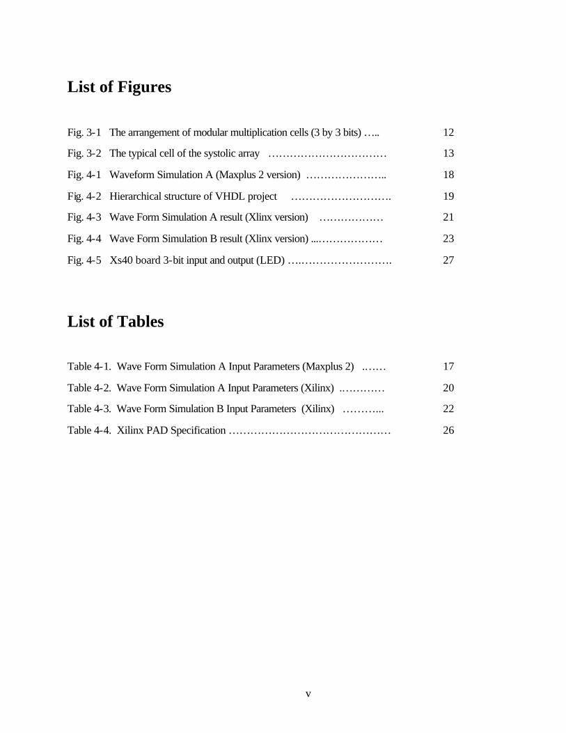
List of Figures
Fig. 3-1 The arrangement of modular multiplication cells (3 by 3 bits) ….. 12
Fig. 3-2 The typical cell of the systolic array …………………………… 13
Fig. 4-1 Waveform Simulation A (Maxplus 2 version) ………………….. 18
Fig. 4-2 Hierarchical structure of VHDL project ………………………. 19
Fig. 4-3 Wave Form Simulation A result (Xlinx version) ……………… 21
Fig. 4-4 Wave Form Simulation B result (Xlinx version) ...……………… 23
Fig. 4-5 Xs40 board 3-bit input and output (LED) ….……………………. 27
List of Tables
Table 4-1. Wave Form Simulation A Input Parameters (Maxplus 2) .…… 17
Table 4-2. Wave Form Simulation A Input Parameters (Xilinx) .………… 20
Table 4-3. Wave Form Simulation B Input Parameters (Xilinx) ………... 22
Table 4-4. Xilinx PAD Specification ……………………………………… 26

1
1. Introduction of RSA crypto system
The network security problem for an increasing traffic of Internet transactions has been
emerged and there have been lots of researches in cryptographic algorithms. RSA [1] system is
among them and widely used today. The system requires fast modular multiplication of integer
numbers containing several hundred bits. The algorithm discussed here is that of providing
hardware to perform modular multiplication using the algorithm proposed by P. L. Montgomery
[2] and further developed by the S. E. Eldridge [3] and Dussé and Kaliski [4]. As cryptography
becomes more widespread, fast cryptographic implementations are becoming important.
Experience with hardware tools has shown that speed often cannot fully be realized unless all
cryptographic methods of interest are implemented in hardware. VHDL language provides good
design tools for constructing systolic arrays as well as graphical ones.
Even though RSA system is not a perfect solution, it provide reasonable security feature over
the Internet with hundred bits of encryption standard. Fast processing of the modular
multiplication is one of the most important key issues on the RSA technology. As data size
demanded over the network grows larger and larger every year, faster processors as well as
sophisticated algorithm which is more effective for the hardware and software are always in high
demand.
In addition to the development of the algorithm in cryptographic software, hardware
implementation of the calculations is desirable for most crypto systems due to its high speed
performance.

2
1-1. Modular Arithmetic
Two numbers are the modular inverse of each other if their product equals 1.
If (AB) mod N = 1 mod N, then B = A-1
The advantage of modular arithmetic is that it is no need to manipulate any huge numbers. The
size of the number is depends on the modular base.
AB mod N = ((A mod N) (B mod N)) mod N,
ABC mod N = ((AB mod N) (C mod N)) mod N,
ABCD mod N = ((AB mod N) (CD mod N)) mod N,
And etc.
This algorithm never looks at any product larger than (N-1)2.
Above multiplication algorithm can be directly applied to compute
Cm mod N, where C=A=B=D=E…
If Cm mod N = 1 mod N, then Cm+1 mod N = C.
With a number C and some power d modulo N,
A = Cd mod N.
By taking the result of the above exponentiation, A, it is possible to raise it to some other power e,
Ae mod N = (Cd)e mod N = Cde mod N.

3
1-2. Fermat’s little theorem.
Leonhard Euler described ϕ (n), phi-function, which is the “exponential period” modulo n for
numbers relatively prime that means it shares only one common factor, namely 1 with n.
For example, ϕ (6) = 2 because only 1 and 5 are relatively prime with 6.
ϕ (7) = 6 because any number less than 7 can share with 7 only 1 as a common factor and they
(1,2,3,4,5 and 6) are all relatively prime with 7. Clearly this result will extend to all prime
numbers. Namely, if p is prime, ϕ (p) = p-1.
For example, if n = 5, a prime number, then ϕ (n) = 4. Set a be 3.
aϕ (n) mod n = 34mod 5
32mod 5 = 4
33mod 5 = 4*3 mod 5 = 2
34mod 5 = 2*3 mod 5 = 1
Fermat’s little theorem is a statement about powers in modular arithmetic in the special case
where the modular base is a prime number. Pohlig and Hellman[5] study a scheme related to
RSA, where exponentiation is done modulo a prime number.
a(p-1) =1 mod p
unless a is a multiple of p which must be a prime number.
Rivest, Shamir, and Adelman[1] designed a fascinating encryption algorithm with Fermat’s little
theorem. Decryption is only possible for the chosen few who have extra information.
For given d, p and computed A = Cd mod p, to find e such that Ae mod p = 1, we can simply find
e such that de = ϕ (p) which equals to p-1. Because then
Ae mod p = Cde mod p = Cϕ (p) mod p = 1 mod p.

4
For given d, p and computed A = Cd mod p, to find e such that Ae mod p = C, we need to find e
such that de = ϕ (p) + 1. Because then
Ae mod p = Cde mod p = Cϕ (p) + 1mod p = C mod p.
From the fact that
(ϕ (p) + 1) mod ϕ (p) = (ϕ (p) + 1) - ϕ (p) = 1 mod ϕ (p),
Therefore, finding e such that de = ϕ (p) + 1 is equivalent to finding e such that de = 1 mod ϕ (p),
which is known as the modular inverse. There is a method known as extended Euclidean
algorithm for computing the modular inverse.

5
1-3. RSA Algorithm
After picking a public exponent d and by finding a prime p, make those two values public. Using
the extended Euclidean algorithm, determine e, the inverse of the public exponent modulo ϕ (p) =
p-1. When people want to send someone a message C, they can encrypt and produce cipher text A
by computing A = Cd mod p. To recover the plain text message, someone compute C = Ae mod p.
But the private key e is the inverse of d modulo p-1. Since p is public, anyone can compute p-1
and therefore determine e.
RSA algorithm solves the above problem by using an Euler’s multiplicative phi-function. If p and
q are relative prime, then ϕ (pq) = ϕ (p) ϕ (q). Hence, for primes p and q and n = pq,
ϕ (n) = (p-1)(q-1).
The problem is finding e that satisfies
d*e = 1 mod (p-1)(q-1)
where the pair (n,d) is the public key and e is the private key. The prime p and q must be kept
secret or destroyed. To compute cipher text A from a plain text message C, find A = Cd mod n. To
recover original message, compute C = Ae mod n . Only the entity that knows e can decrypt.
Because of the relationship between d and e, the algorithm correctly recovers the original message
C, since
Ae mod n = Cde mod n = C1mod n = C mod n.
To know ϕ (n) one must know p and q. In other words, they must factor n. Multiplying big prime
numbers can be a one-way function. Factoring takes a certain number of steps, and the number of
steps increases sub-exponentially as the size of the number increases. Extended Euclidean
algorithm can be used to find private key e.

6
Using this fact, it is natural to build the private key using two primes and the public key using
their product. There is one more condition, the public exponent d, must be relatively prime with
(p-1)(q-1) to exist a modular inverse e.
In practice, one would generally pick d, the public exponent first, then find the primes p and q
such that d is relatively prime with (p-1)(q-1). There is no mathematical requirement to do so, it
simply makes key pair generation a little easier. In fact, the two most popular d’s in use today are
F0 = 3 and F4 = 65,537. The F in F0 and F4 stands for Pierre de Fermat.

7
2. Montgomery’s Algorithm
In RSA cryptography system, it requires lots of modular multiplication. Montgomery proposed an
algorithm that conducts the modular multiplication without trial division but produces some
residue. This algorithm is suitable for hardware or software implementation.
Let N be an integer (the modulus) and let R be an integer relatively prime to N. We represent the
residue class A mod N as AR mod N and redefine modular multiplication as
Mont_Product (A, B, N, R) = ABR-1mod N.
It is not hard to verify that Montgomery multiplication in the new representation is isomorphic to
modular multiplication in the ordinary one:
Mont_Product (AR mod N, BR mod N, N, R) = (AB)R mod N.
Since AR mod N and BR mod N are both less than N, their product is less than NN that is less
than RN, so it forms a legal input for Mont_Product. A drawback of the algorithm is the
redundant factor of R for the desired result, (AB) mod N.
We can similarly redefine modular exponentiation as repeated Montgomery multiplication. This
“Montgomery exponentiation” can be computed with all the usual modular exponentiation
speedups.
Montgomery’s theorem
Let N and R be relatively prime integers (RR’ NN’ = 1, 0 < N’ <R), and let N’ = -N-1mod
R.

8
Then for all integers T, (T+MN)/R is an integer satisfying
(T+MN)/R = TR-1 mod N
where M = TN’ mod R.
If we choose the right R, a power of base in which we represent multiple-precision integers, then
division by R and reduction modulo R are trivial. With such an R Montgomery reduction is no
more expensive than two multiple-precision products.
The method represents as a function:
Function REDC(x) //x = AB
m = (x mod R) * N’ mod R
t = (x + m*N) / R
If t < N
return t
else return t-N.
we need x+m*N to be divisible by R. mN = ((x mod R) N’ mod R) N = xNN’ mod R = -x mod
R. x +mN = (x + -x) mod R = 0 mod R. Thus R divides x + mN.
Next, x + mN = x mod N
tR = x mod N
t = x R’ mod N (where R’ = R-1 mod N)
Thus t is congruent mod N to the desired result. If x < RN, then t < 2N, so either t or t-N is the
answer.
m < R
x + mN < RN + RN

9
(x + mN) /R < 2N
Thus REDC(x) returns xR’mod N given 0 ≤ x <RN.
In hardware implementation, use n0’ = -N-1 mod bi instead of using –N’mod R for base bi. R = bn.
The program becomes
Mont_Product (A, B, N, R)
for i = 0 to n-1 do begin
T: = T + A[i] * B* bi;
M: = T[i]*n0’mod bn;
T: = T + m*N* bi;
end;
return T/R;
end;
The procedure divides only by R = bn, so all divisions can be done by shifting out low order bits.
The time consuming part is the two multiplications.
10
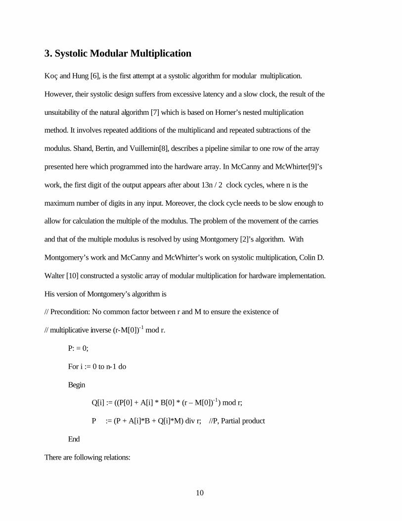
3. Systolic Modular Multiplication
Koç and Hung [6], is the first attempt at a systolic algorithm for modular multiplication.
However, their systolic design suffers from excessive latency and a slow clock, the result of the
unsuitability of the natural algorithm [7] which is based on Horner’s nested multiplication
method. It involves repeated additions of the multiplicand and repeated subtractions of the
modulus. Shand, Bertin, and Vuillemin[8], describes a pipeline similar to one row of the array
presented here which programmed into the hardware array. In McCanny and McWhirter[9]’s
work, the first digit of the output appears after about 13n / 2 clock cycles, where n is the
maximum number of digits in any input. Moreover, the clock cycle needs to be slow enough to
allow for calculation the multiple of the modulus. The problem of the movement of the carries
and that of the multiple modulus is resolved by using Montgomery [2]’s algorithm. With
Montgomery’s work and McCanny and McWhirter’s work on systolic multiplication, Colin D.
Walter [10] constructed a systolic array of modular multiplication for hardware implementation.
His version of Montgomery’s algorithm is
// Precondition: No common factor between r and M to ensure the existence of
// multiplicative inverse (r-M[0])-1 mod r.
P: = 0;
For i := 0 to n-1 do
Begin
Q[i] := ((P[0] + A[i] * B[0] * (r – M[0])-1) mod r;
P := (P + A[i]*B + Q[i]*M) div r; //P, Partial product
End
There are following relations:

11
RiPi = Ai * B + Qi*M
RnP = A*B + Q*M
So P = (r-n AB) mod M with extra power of r. To remove the factor, do extra application of the
same operation with inputs P and r2n mod M.
A key property of Montgomery’s algorithm is that the choice of modulus multiple is based on the
lowest digit P[0] of the partial product. With this multiple Q[i] determined, the digits of the i + 1st
partial product P i+1 can be computed in order starting with the lowest.
With Q[i] known, digits output from one addition cycle enable the corresponding digits for the
next cycle to be found. In Fig. 3-1, each row performs an iteration of the loop and columns
compute successive values for a single digit position. The typical cell performs a sing digit
calculation of the assignment P, and generates a carry in the normal way.
Pi+1[j-1] + r*CarryOut = Pi[j] + A[i]*B[j] + Q[i]*M[j] + CarryIn.
The cells are all identical with the exception of the rightmost column which does not need carry in
and Q[i]. The first output digit of a modular multiplication appears after 2n + 2 clock cycle. A
depth of 5 gates suffices for the typical cell shown in Fig. 3-2, and less for the right most cells,
which do not need carries and inputs of Q[i].

12
Fig. 3-1. The Arrangement of modular multiplication cells (3 by 3 bits)

13
Fig. 3-2 The typical cell of the systolic array
14
4. VHDL Implementation of Systolic Array
4-1. VHDL language
VHDL[11] is a hardware description language intended for documenting and modeling digital
systems ranging from a small chip to a large system. It can be used to model a digital system
at any level of abstraction raging from the architectural level down to the gate level.
The language was initially developed specifically for Department of Defense VHSIC
(Very High Speed Integrated Circuits) contractors. However, due to an overwhelming need in
the industry for a standard hardware description language, the VHSIC Hardware Description
Language (VHDL) was selected and later approved to become an IEEE standard [12] called
the IEEE Std 1076-1987.
The language was updated again in 1993 to include a number of clarifications in addition to a
number of new features like report statement and pulse rejection limit. The codes of the
VHDL implementation are based on this version of the language called the IEEE Std 1076-
1993.
4-2. Design Units
VHDL has several subunits in order to provide organized frame structure of the
programming. The followings are basic units of VHDL.

15
A. Entity declaration
An entity declaration describes the interface of the design to its external environments,
that is, it describes the ports (inputs, outputs, etc.) through which the design communicates
with other designs.
B. Architecture body
An architecture body describes the composition or functionality of a design. This could be
described as a mix of sequential behavior, concurrent behavior, and components. A design
may have more than one architecture body, each describing a different composition, that
is, using a different behavior of design.
C. Configuration declaration
A configuration declaration is used to specify the bindings of components present in an
architecture body to other design entities. An entire hierarchy of design, that is, the
bindings that link all the design entities in a hierarchy, can also be specified using the
configuration declaration.
D. Package declaration
A package declaration is a repository to store commonly used declaration.
E. Package body

16
A package body is always associated with a package declaration and contains subprogram
bodies, along with other declarations.
F. Generate statement [13]
This statement is executed at elaboration time. The execution either causes replication of
concurrent statements or causes conditional selection of concurrent statements.
G. Loop statement
The execution of the loop causes the statements within the loop to be iterated the specified
number of times. A loop statement can be a for-loop, a while-loop or a repeat-forever-
loop.

17
4.3 Wave Form Simulations
4-3-1. Experiment with Maxplus2 software
1. Simulation A. To verify the systolic array design model, with Maxplus 2 software made by Altera Corporation, simulation of VHDL code has been carried out prior to the hardware implementations. First one is type A simulation with the following parameters shown in Table 4-1.
Table 4-1. Wave Form Simulation A Input Parameters (Maxplus 2)
Pre-conditions Pre-defined Inputs Outputs
(R) (P) = AB (mod M) rR – nM = 1 where r is radix, n is number of bits, R = r n = 2 3 = 8
P = PI2 = 0
A = AI2= 7
P = POUT2 = 7
0 < r < M
CLOCK = CLB5 = CLM5
B = BI2 = 3
0 < M < r n
M = MI2 = 5

18
Fig 4-1. Waveform Simulation A (Maxplus 2 version)

19
4-3-2. Experiment with Xilinx software
Fig 4.2 shows general procedure from VHDL programming to the hardware implementations.
The simulation has been done by Xilinx Foundation software with Lab book. VHDL codes are
check by compiler and bit stream file that is fit to the specific FLGA device, XC4010E.
Fig. 4-2 Hierarchical structure of VHDL project

20
1. Simulation A.
To verify the systolic array design model, with Xilinx software made by Xilinx Corporation, simulation of VHDL code has been carried out prior to the hardware implementations. Second one is type A simulation with the following parameters shown in Table 4-2.
Table 4-2. Wave Form Simulation A Input Parameters (Xilinx)
Pre-conditions Pre-defined Inputs Outputs
(R) (P) ≡ AB (mod M) rR – nM = 1 where r is radix, n is number of bits, R = r n = 2 3 = 8
P = PI2 = 0
A = AI2= 7
P = POUT2 = 7
0 < r < M
CLOCK = CLB5 = CLM5
B = BI2 = 3
0 < M < r n
M = MI2 = 5

21
Fig 4-3. Wave Form Simulation A result (Xlinx version)

22
2. Simulation B.
To verify the systolic array design model, with Xilinx software made by Xilinx Corporation, simulation of VHDL code has been carried out prior to the hardware implementations. Third one is type B simulation with the following parameters shown in Table 4-3.
Table 4-3. Wave Form Simulation B Input Parameters (Xilinx)
Pre-conditions Pre-defined Inputs Outputs
(R) (P) ≡ AB (mod M) rR – nM = 1 where r is radix, n is number of bits, R = r n = 2 3 = 8
P = PI2 = 0
A = AI2= 6
P = POUT2 = 3
0 < r < M
CLOCK = CLB5 = CLM5
B = BI2 = 4
0 < M < r n
M = MI2 = 5

23
Fig 4-4. Wave Form Simulation B result (Xlinx version)

24
4.4 Hardware Experiment
4-4-1. Field Programmable Logic Device
Computer-aided design and programmable logic architecture have been developed to
remove the drudgery from building digital circuits and make flexibility on the designing the
systems. In practical engineering, the details of the logic circuit needed to realize the truth
table are worked out by a logic-synthesis program. Then, the operation of the logic circuit is
checked using a simulation program. If the circuit simulates correctly, the gates and wires are
mapped into a field programmable gate array (FPGA) or complex programmable logic device
(CPLD) IC using specialized place & route or fitter programs.
These field programmable logic devices (FPLD) contain logic gates and the means for
interconnecting them within a single integrated circuit. The software programs determine how
the gates in the device can be connected to build the logic circuit. The program’s output is a
bit-stream configuration file that is downloaded into the FPLD to make it act like logic circuit.
The FPLD can then be placed into a larger circuit where it will perform its functions after
some possible debugging.
4-4-2. Experiment Procedure
Following is the experimental procedure using XC40 FLGA board, XESS software tools and
Xilinx CAD tool [14].
A. General procedure
1. Generate bit stream file and port specification file in the design program
2. Download to the FLGA board
3. Connect wires to the specified port number for FLGA

25
4. Check and debug the design using the LED outputs
B. Detail procedure
1. Copy bit stream file(.bit) and port specification file(.pad) generated by Xilinx VHDL
implementation step into the XESS tool directory.
E.g.) copy c:\fndtm\Active\Projects\starray\xproj\ver10\rev2\starray.bit c:\xstool\bin
2. Disconnect the all the wires previously connected to FLGA on the board
3. Connect DC9V power adapter with female-center positive to the board.
4. Connect the parallel cable between PC LPT1 port and XC40 board.
5. Test the initial board status with XESS software, XSTEST.exe
E.g.) c:\xstool\bin\xstest xs40-010e
If the board shows blinking signal on the LED display, then the board is ready.
6. Download bit-stream file to the board and build the circuit in the FLGA.
7. Find the negative port number (52) and connect the wire.
8. Put the LED lights on the board
9. Connect all the wires on the board based on the port numbers of the starray.pad file. Port numbers
with input 1 represent positive polarity and numbers with input 0 represent negative one on the
board.
10. Check the series of LED lights as a result.
11. For the new wiring as a debugging, go to step 2 again.

26
Table 4-4. Xilinx PAD Specification PAR: Xilinx Place And Route M1.5.19. Xilinx PAD Specification File ***************************** Input file: map.ncd Output file: starray.ncd Part type: xc4010e Speed grade: -1 Package: pc84 Pinout by Pin Name: +------------------------------------------------+-----------+--------------+ | Pin Name | Direction | Pin Number | +------------------------------------------------+-----------+--------------+ | AI<0> | INPUT | P7 | | AI<1> | INPUT | P16 | | AI<2> | INPUT | P82 | | BI<0> | INPUT | P40 | | BI<1> | INPUT | P20 | | BI<2> | INPUT | P84 | | CLB<0> | INPUT | P44 | | CLB<1> | INPUT | P23 | | CLB<2> | INPUT | P81 | | CLB<3> | INPUT | P50 | | CLB<4> | INPUT | P62 | | CLB<5> | INPUT | P35 | | CLM<0> | INPUT | P66 | | CLM<1> | INPUT | P65 | | CLM<2> | INPUT | P27 | | CLM<3> | INPUT | P10 | | CLM<4> | INPUT | P3 | | CLM<5> | INPUT | P71 | | MI<0> | INPUT | P67 | | MI<1> | INPUT | P68 | | MI<2> | INPUT | P18 | | PI<0> | INPUT | P24 | | PI<1> | INPUT | P19 | | PI<2> | INPUT | P5 | | POUT<0> | OUTPUT | P4 | | POUT<1> | OUTPUT | P6 | | POUT<2> | OUTPUT | P83 | +------------------------------------------------+-----------+--------------+

27
Fig. 4-5. XS40 board with Xilinx XC4010E FPGA

28
5. Conclusion
Systolic array design with the Montgomery’s algorithm has been simulated by VHDL
language and software simulators. The three simulations of VHDL implementations showed
desired results of modular multiplications. The VHDL implementation has shown that the
language provides a useful tool of practicing the algorithms without drawings of large amounts of
logic gates. And it also gives effectiveness on designing and simulations of microprocessor.
Pipelining capability of design with clock cycles and VHDL coding of arbitrary size of input and
output bits with ‘Generate’ statement are remained as a further study.
References

29
1. R. L. Rivest, A. Shamir, and L. Adleman, “ A method for obtaining digital signatures and
public key cryptosystems,” Communication, ACM. Vol. 21, pp. 120- 126, 1978
2. P. L. Montgomery, “Modular multiplication without trial division,” Mathematics of
Computation, Vol. 44, pp. 519 – 521, 1985
3. S.E. Eldridge and C.D. Walter “ Hardware implementation of Montgome
multiplication algorithm,” IEEE Trans. Compt., Vol. 42, no 6, pp. 693, 1993
4. S.R. Dusse and B. S. Kaliski Jr., “A cryptographic library for the Motorola DSP 5600,” in
Advances in Cryptology – EUROCRYPT ’90, Vol. 473, 1991, pp. 51-60.
5. Pohlig, S.C., and Hellman, M.E., “An improved algorithm for computing logarithms over
GF(p) and its cryptographic significance.” IEEE Trans. Inform. Theory, 1978.
6. Ç. K. Koç and C. Y. Hung, “Bit-level systolic arrays for modular multiplication’, J. VLSI
Signal Processing.” Vol. 3, pp. 215-223, 1991.
7. E. F. Brickel, “A fast modular multiplication algorithm with application to tow-key
cryptography”, in Advances in Cryptology-Proc. of CRYPTO 82, Chaum et al., Eds. New
York: Plenum, 1983, pp. 51-60.
8. M. Shand, P. Bertin, and J. Vuillemin, “Hardware speedups in long integer multiplication”,
ACM Sigarch, Vol. 19, pp. 106-113, 1991.
9. J. V. McCanny and J. G. McWhirter, “Implementation of signal processing functions using 1-
bit systolic arrays”, Electron, Letters, Vol. 18, pp. 241-243, 1982.
10. Colin D. Walter, “Systolic Modular Multiplication”, IEEE Transactions on Computers, Vol.
42, No. 3, pp. 376, March 1993.

30
11. J. Bhasker, A VHDL synthesis primer, Star Galaxy Publishing, New York, 1996
12. Zoran Salcic, Asim Smailagic, Digital System Design and Prototyping using Field
Programmabel Logic, Kluwer Academic Publishers, 1997
13. Peter J. Ashenden, The Designers’ guide to VHDL, Morgan Kaufmann Publishers, Inc. pp.
351, Netherlands, 1996
14. David Van den Bout, The practical Xilinx designer lab book, version 1.5, Prentice-Hall, New
York, 1999
Appendices
Appendix A.

31
VHDL code of systolic array for modular multiplication - Maxplus2 version
Typical Cell (Cell.vhd) LIBRARY ieee; USE ieee.std_logic_1164.ALL; LIBRARY usrlib; USE usrlib.cellunit.ALL; ENTITY cell IS PORT (A1, B1, C1, D1, M1, P1, Q1:in STD_LOGIC; A2, B2, C2, D2, M2, P2, Q2:out STD_LOGIC); END cell; ARCHITECTURE A OF cell IS SIGNAL X1, X2, X3, X4, Y1, Y2, Y3, Z1, Z2, Z3, Z4: STD_LOGIC; BEGIN and1: andGate PORT MAP (A1, B1, A2, B2, X1); and2: andGate PORT MAP (M1, Q1, M2, Q2, X2); ha1: hAdder PORT MAP (X1, X2, X3, X4); ha2: hAdder PORT MAP (P1, C1, Y2, Y1); or1: orGate PORT MAP (D1, Y1, Y3); ha3: hAdder PORT MAP (Y2, X3, P2, Z1); ha4: hAdder PORT MAP (X4, Y3, Z2, Z4); ha5: hAdder PORT MAP (Z1, Z2, C2, Z3); or2: orGate PORT MAP (Z3, Z4, D2); END A; Right most Cells (Cell_right.vhd) LIBRARY ieee; USE ieee.std_logic_1164.ALL; LIBRARY usrlib; USE usrlib.cellunit.ALL; ENTITY cell_right IS PORT (A1, B1, M1, P1:in STD_LOGIC; A2, B2, C2, D2, M2, P2, Q2:out STD_LOGIC); END cell_right; ARCHITECTURE A OF cell_right IS

32
SIGNAL Q1, X1, X2, X3, X4, Y1, Z1: STD_LOGIC; BEGIN and1: andGate PORT MAP (A1, B1, A2, B2, X1); Q1 <= P1 XOR X1; and2: andGate PORT MAP (M1, Q1, M2, Q2, X2); ha1: hAdder PORT MAP (X1, X2, X3, X4); ha3: hAdder PORT MAP (P1, X3, P2, Z1); ha5: hAdder PORT MAP (Z1, X4, C2, D2); END A; The Systolic Array (sys3.vhd) LIBRARY ieee; USE ieee.std_logic_1164.ALL; LIBRARY usrlib; USE usrlib.cellunit.ALL; USE usrlib.ffunit.ALL; ENTITY syst3 IS PORT (CLK: IN STD_LOGIC; AI: IN STD_LOGIC_VECTOR (2 DOWNTO 0); BI: IN STD_LOGIC_VECTOR (2 DOWNTO 0); MI: IN STD_LOGIC_VECTOR (2 DOWNTO 0); PI: IN STD_LOGIC_VECTOR (2 DOWNTO 0); POUT:OUT STD_LOGIC_VECTOR (2 DOWNTO 0)); END syst3; ARCHITECTURE a OF syst3 IS SIGNAL BL: STD_LOGIC_VECTOR(5 DOWNTO 0); SIGNAL ML: STD_LOGIC_VECTOR(5 DOWNTO 0); SIGNAL A: STD_LOGIC_VECTOR(8 DOWNTO 0); SIGNAL B: STD_LOGIC_VECTOR(8 DOWNTO 0); SIGNAL C: STD_LOGIC_VECTOR(8 DOWNTO 0); SIGNAL D: STD_LOGIC_VECTOR(8 DOWNTO 0); SIGNAL M: STD_LOGIC_VECTOR(8 DOWNTO 0); SIGNAL P: STD_LOGIC_VECTOR(8 DOWNTO 0); SIGNAL Q: STD_LOGIC_VECTOR(8 DOWNTO 0); BEGIN cell0: cell_right PORT MAP (AI(0), BI(0), MI(0), PI(0), A(0), B(0), C(0), D(0), M(0), P(0), Q(0)); cell1: cell PORT MAP (A(0), BI(1), C(0), D(0), MI(1), PI(1), Q(0),

33
A(1), B(1), C(1), D(1), M(1), P(1), Q(1)); cell2: cell PORT MAP (A(1), BI(2), C(1), D(1), MI(2), PI(2), Q(1), A(2), B(2), C(2), D(2), M(2), P(2), Q(2)); lch0b: latch1 PORT MAP (CLK, B(0), BL(0)); lch1b: latch1 PORT MAP (CLK, B(1), BL(1)); lch2b: latch1 PORT MAP (CLK, B(2), BL(2)); lch0m: latch1 PORT MAP (CLK, M(0), ML(0)); lch1m: latch1 PORT MAP (CLK, M(1), ML(1)); lch2m: latch1 PORT MAP (CLK, M(2), ML(2)); cell3: cell_right PORT MAP (AI(1), B(0), M(0), P(1), A(3), B(3), C(3), D(3), M(3), P(3), Q(3)); cell4: cell PORT MAP (A(3), B(1), C(3), D(3), M(1), P(2), Q(3), A(4), B(4), C(4), D(4), M(4), P(4), Q(4)); cell5: cell PORT MAP (A(4), B(2), C(4), D(4), M(2), C(2), Q(4), A(5), B(5), C(5), D(5), M(5), P(5), Q(5)); lch3b: latch1 PORT MAP (CLK, B(3), BL(3)); lch4b: latch1 PORT MAP (CLK, B(4), BL(4)); lch5b: latch1 PORT MAP (CLK, B(5), BL(5)); lch3m: latch1 PORT MAP (CLK, M(3), ML(3)); lch4m: latch1 PORT MAP (CLK, M(4), ML(4)); lch5m: latch1 PORT MAP (CLK, M(5), ML(5)); cell6: cell_right PORT MAP (AI(2), B(3), M(3), P(4), A(6), B(6), C(6), D(6), M(6), P(6), Q(6)); cell7: cell PORT MAP (A(6), B(4), C(6), D(6), M(4), P(5), Q(6), A(7), B(7), C(7), D(7), M(7), P(7), Q(7)); cell8: cell PORT MAP (A(7), B(5), C(7), D(7), M(5), C(5), Q(7), A(8), B(8), C(8), D(8), M(8), P(8), Q(8)); POUT(0) <= P(7); POUT(1) <= P(8); POUT(2) <= C(8); END a; Appendix B.
VHDL code of systolic array for modular multiplication - Xilinx version

34
syst.vhd – the main program
library IEEE, usr; use IEEE.std_logic_1164.all; use usr.cells.ALL; entity syst is port(CLB: in STD_LOGIC_VECTOR (5 downto 0); CLM: in STD_LOGIC_VECTOR (5 downto 0); AI: in STD_LOGIC_VECTOR (2 downto 0); BI: in STD_LOGIC_VECTOR (2 downto 0); MI: in STD_LOGIC_VECTOR (2 downto 0); PI: in STD_LOGIC_VECTOR (2 downto 0); POUT: out STD_LOGIC_VECTOR (2 downto 0)); end syst; architecture syst_arch of syst is COMPONENT cell_right PORT (AR1, BR1, MR1, PR1:in STD_LOGIC; AR3, BR3, CR3, DR3, MR3, QR3:out STD_LOGIC); END component; COMPONENT cell PORT (A1, B1, C1, D1, M1, P1, Q1:in STD_LOGIC; A2, B2, C2, D2, M2, P2, Q2:out STD_LOGIC); END component; COMPONENT latch1 PORT(CLK: IN STD_LOGIC; D : IN STD_LOGIC; Q : OUT STD_LOGIC); END component; SIGNAL BL: STD_LOGIC_VECTOR(5 DOWNTO 0); SIGNAL ML: STD_LOGIC_VECTOR(5 DOWNTO 0); SIGNAL A: STD_LOGIC_VECTOR(8 DOWNTO 0); SIGNAL B: STD_LOGIC_VECTOR(8 DOWNTO 0); SIGNAL C: STD_LOGIC_VECTOR(8 DOWNTO 0); SIGNAL D: STD_LOGIC_VECTOR(8 DOWNTO 0); SIGNAL M: STD_LOGIC_VECTOR(8 DOWNTO 0); SIGNAL P: STD_LOGIC_VECTOR(8 DOWNTO 0); SIGNAL Q: STD_LOGIC_VECTOR(8 DOWNTO 0);

35
BEGIN cell0: cell_right PORT MAP (AI(0), BI(0), MI(0), PI(0), A(0), B(0), C(0), D(0), M(0), Q(0)); cell1: cell PORT MAP (A(0), BI(1), C(0), D(0), MI(1), PI(1), Q(0), A(1), B(1), C(1), D(1), M(1), P(1), Q(1)); cell2: cell PORT MAP (A(1), BI(2), C(1), D(1), MI(2), PI(2), Q(1), A(2), B(2), C(2), D(2), M(2), P(2), Q(2)); lch0b: latch1 PORT MAP (CLB(0), B(0), BL(0)); lch1b: latch1 PORT MAP (CLB(1), B(1), BL(1)); lch2b: latch1 PORT MAP (CLB(2), B(2), BL(2)); lch0m: latch1 PORT MAP (CLM(0), M(0), ML(0)); lch1m: latch1 PORT MAP (CLM(1), M(1), ML(1)); lch2m: latch1 PORT MAP (CLM(2), M(2), ML(2)); cell3: cell_right PORT MAP (AI(1), BL(0), ML(0), P(1), A(3), B(3), C(3), D(3), M(3), Q(3)); cell4: cell PORT MAP (A(3), BL(1), C(3), D(3), ML(1), P(2), Q(3), A(4), B(4), C(4), D(4), M(4), P(4), Q(4)); cell5: cell PORT MAP (A(4), BL(2), C(4), D(4), ML(2), C(2), Q(4), A(5), B(5), C(5), D(5), M(5), P(5), Q(5)); lch3b: latch1 PORT MAP (CLB(3), B(3), BL(3)); lch4b: latch1 PORT MAP (CLB(4), B(4), BL(4)); lch5b: latch1 PORT MAP (CLB(5), B(5), BL(5)); lch3m: latch1 PORT MAP (CLM(3), M(3), ML(3)); lch4m: latch1 PORT MAP (CLM(4), M(4), ML(4)); lch5m: latch1 PORT MAP (CLM(5), M(5), ML(5)); cell6: cell_right PORT MAP (AI(2), BL(3), ML(3), P(4), A(6), B(6), C(6), D(6), M(6), Q(6)); cell7: cell PORT MAP (A(6), BL(4), C(6), D(6), ML(4), P(5), Q(6), A(7), B(7), C(7), D(7), M(7), P(7), Q(7)); cell8: cell PORT MAP (A(7), BL(5), C(7), D(7), ML(5), C(5), Q(7), A(8), B(8), C(8), D(8), M(8), P(8), Q(8)); POUT(0) <= P(7); POUT(1) <= P(8); POUT(2) <= C(8); end syst_arch; usr.vhd - contains component packages - cell, cell_right and latch1
-- USR.VHD LIBRARY ieee; USE ieee.std_logic_1164.ALL; PACKAGE cells IS

36
COMPONENT latch1 PORT(CLK, D: IN STD_LOGIC; Q : OUT STD_LOGIC); END COMPONENT; COMPONENT cell PORT (A1, B1, C1, D1, M1, P1, Q1:in STD_LOGIC; A2, B2, C2, D2, M2, P2, Q2:out STD_LOGIC); END COMPONENT; COMPONENT cell_right PORT (AR1, BR1, MR1, PR1:in STD_LOGIC; AR3, BR3, CR3, DR3, MR3, QR3: OUT STD_LOGIC); END COMPONENT; END cells; LIBRARY IEEE; USE IEEE.std_logic_1164.ALL; ENTITY latch1 IS PORT(CLK, D: IN STD_LOGIC; Q : OUT STD_LOGIC); END latch1; ARCHITECTURE latch1_arch OF latch1 IS BEGIN PROCESS(clk, d) BEGIN IF CLK = '1' THEN Q <= D; END IF; END PROCESS; END latch1_arch; LIBRARY ieee; USE ieee.std_logic_1164.ALL; ENTITY cell IS PORT (A1, B1, C1, D1, M1, P1, Q1:in STD_LOGIC; A2, B2, C2, D2, M2, P2, Q2:out STD_LOGIC); END cell;

37
ARCHITECTURE cell_arch OF cell IS SIGNAL X1, X2, X3, X4, Y1, Y2, Y3, Z1, Z2, Z3, Z4: STD_LOGIC; BEGIN and1: X1 <= A1 AND B1; A2 <= A1; B2 <= B1; and2: X2 <= M1 AND Q1; M2 <= M1; Q2 <= Q1; ha1: X3 <= X1 XOR X2; X4 <= X1 AND X2; ha2: Y2 <= P1 XOR C1; Y1 <= P1 AND C1; Y3 <= D1 OR Y1; ha3: P2 <= Y2 XOR X3; Z1 <= Y2 AND X3; ha4: Z2 <= X4 XOR Y3; Z4 <= X4 AND Y3; ha5: C2 <= Z1 XOR Z2; Z3 <= Z1 AND Z2; D2 <= Z3 OR Z4; END cell_arch; LIBRARY IEEE; USE IEEE.std_logic_1164.ALL; ENTITY cell_right IS PORT (AR1, BR1, MR1, PR1:in STD_LOGIC; AR3, BR3, CR3, DR3, MR3, QR3: OUT STD_LOGIC); END cell_right; ARCHITECTURE cell_right_arch OF cell_right IS SIGNAL QR1, XR1, XR2, XR3, XR4, ZR1: STD_LOGIC;

38
BEGIN XR1 <= AR1 AND BR1; AR3 <= AR1; BR3 <= BR1; QR1 <= PR1 XOR XR1; XR2 <= MR1 AND QR1; MR3 <= MR1; QR3 <= QR1; XR3 <= XR1 XOR XR2; XR4 <= XR1 AND XR2; ZR1 <= PR1 AND XR3; CR3 <= ZR1 XOR XR4; DR3 <= ZR1 AND XR4; END cell_right_arch;