vhdl 360 - unimasr.com • home | cairo university - faculty …€¦ · · 2012-01-31moore fsm...
TRANSCRIPT

VHDL 360©
by: Mohamed Samy Samer El-Saadany

Copyrights Copyright © 2010/2011 to authors. All rights reserved • All content in this presentation, including charts, data, artwork and
logos (from here on, "the Content"), is the property of Mohamed Samy and Samer El-Saadany or the corresponding owners, depending on the circumstances of publication, and is protected by national and international copyright laws.
• Authors are not personally liable for your usage of the Content that entailed casual or indirect destruction of anything or actions entailed to information profit loss or other losses.
• Users are granted to access, display, download and print portions of this presentation, solely for their own personal non-commercial use, provided that all proprietary notices are kept intact.
• Product names and trademarks mentioned in this presentation belong to their respective owners.
VHDL 360 © 2

Module 5
Modeling FSMs

Objective
• Introducing Finite State Machine Modeling • Skills gained:
– Modeling Finite State Machines – Identify different State Machine styles – Understanding State Encoding
VHDL 360 © 4

Outline • FSM • Moore Style • Mealy Style • Moore vs. Mealy • FSM Tips • State Machine Encoding
VHDL 360 © 5
6
What is FSM?
Data Part
Control Part
Inputs Outputs
Controls
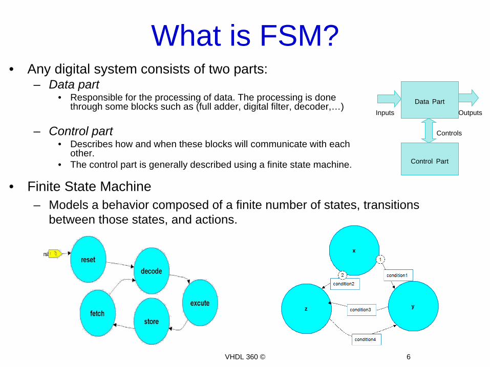
• Any digital system consists of two parts: – Data part
• Responsible for the processing of data. The processing is done through some blocks such as (full adder, digital filter, decoder,…)
– Control part • Describes how and when these blocks will communicate with each
other. • The control part is generally described using a finite state machine.
VHDL 360 ©
• Finite State Machine – Models a behavior composed of a finite number of states, transitions
between those states, and actions.

State Machine • Consists of:
– States • unique configurations of information in a machine
– Transitions • Transaction between states
– Transition conditions • Condition based on which the machine moves
from one state to another – Transition actions
• An action associated with a transition – State Actions
• Actions associated with a given state
7 VHDL 360 ©

FSM STYLES
VHDL 360 © 8

Moore FSM • State machine outputs are dependent only on the present state
information (output vector (Y) is function of the state vector (S)). • Outputs don’t react immediately to input change. • Moore machines effectively filter out transients, and can be used to
eliminate race conditions when inputs are unfiltered.
Outputs = f(S)
State Registers
Next state
Present state Outputs
Inputs
Output Logic
Next State Logic
9 VHDL 360 ©

Moore Implementation
10 VHDL 360 ©

Mealy FSM • State machine outputs are dependent on the inputs and the present
state information (output vector (Y) is function of the state vector (S) and the input (C)).
• Outputs react immediately to input changes. • Mealy machines are used to create control blocks that respond
quickly to external signal changes. • Care must be taken to isolate the design from transients and race
conditions
Outputs = f(inputs, S)
State Registers
Next state
Inputs Output Logic
Next State Logic
Outputs
11
Present state
VHDL 360 ©

Mealy Implementation
12 VHDL 360 ©

FSM Styles
Moore
• How can we implement FSMs using VHDL?
13
Outputs = f(S)
State Registers
Next state
Present state Outputs
Inputs Output Logic
Next State Logic
Mealy
Outputs = f(inputs, S)
State Registers
Next state
Present state
Inputs Output Logic
Next State Logic
Outputs
VHDL 360 ©
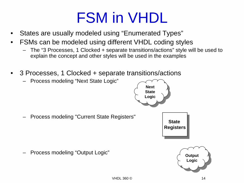
FSM in VHDL • States are usually modeled using “Enumerated Types” • FSMs can be modeled using different VHDL coding styles
– The “3 Processes, 1 Clocked + separate transitions/actions” style will be used to explain the concept and other styles will be used in the examples
• 3 Processes, 1 Clocked + separate transitions/actions
– Process modeling “Next State Logic”
– Process modeling "Current State Registers"
– Process modeling “Output Logic”
14
State Registers
Output Logic
Next State Logic
VHDL 360 ©

Next-State Logic
process ( current_state, <in1>, <in2>, <in3> … ) Begin case ( Current_State ) is when <state1> => if ( <condition (<in1>, <in2>...)> ) then Next_State <= <state2>; elsif ( <condition (<in1>, <in2>...)> ) then Next_State <= <state3>; ... end process;
• Use a combinational ‘process’ to model next state logic*
15
*Please refer to module 4: Synthesis examples VHDL 360 ©
Next State Logic

Current State Logic • Use a sequential ‘process’ to describe current state logic*
Process (clock) Begin if rising_edge (clock) then if ( reset = '1' ) then -- synchronous reset Current_State <= <reset_state>; else Current_State <= Next_State; end if; end if; end process;
16
*Please refer to module 4: Synthesis examples VHDL 360 ©
State Registers

Assigning Moore Outputs • Use a combinational ‘process’ to model Output Logic
– Outputs are only dependant on the current state – Take care not to infer latches* – Take care of the sensitivity list*
Outputs = f(S)
17
Output Logic
process (current_state ) begin case ( current_state) is when <State1> => <Out1> <= <value1>; <Out2> <= <value2>; when <State2> => <Out1> <= <value3>; <Out2> <= <value4>; ... end process;
*Please refer to module 4: Synthesis examples VHDL 360 ©

Assigning Mealy Outputs • Use a combinatorial ‘process’ to model Output Logic
– Outputs are dependant on the current state & the input – Take care not to infer latches* – Take care of the sensitivity list*
18
Outputs = f(Inputs, S)
Output Logic
process ( Current_State, <in1>, <in2>, <in3> ...) begin case ( Current_State ) is when <State1>=> if ( <condition (<in1>, <in2>...)> ) then <Out1> <= <value1>; <Out2> <= <value2>; elsif ( <condition (<in1>, <in2>...)> ) then <Out1> <= <value3>; <Out2> <= <value4>; ... when <State2> => . . . end process;
*Please refer to module 4: Synthesis examples VHDL 360 ©

Moore vs. Mealy • Let’s illustrate the difference between Moore & Mealy machines using
an "Parity Checker" that samples the input “x” each clock cycle • The “reset” is asynchronous • When the “reset” is asserted high, the output “y” will be '0' • Otherwise it checks the parity of the input stream
– When even, y will be '0' – When odd, y will be '1'
19 VHDL 360 ©

Moore vs. Mealy
20
• The state diagram will be:
Moore Implementation Mealy Implementation
VHDL 360 ©
• Let’s illustrate the difference between Moore & Mealy machines using an "Parity Checker" that samples the input “x” each clock cycle • The “reset” is asynchronous • When the “reset” is asserted high, the output “y” will be '0' • Otherwise it checks the parity of the input stream
– When even, y will be '0' – When odd, y will be '1'

Moore vs. Mealy
21
Moore Implementation Mealy Implementation
LIBRARY ieee; USE ieee.std_logic_1164.ALL; ENTITY parity_moore IS port( clk : in std_logic; reset : in std_logic; x : in std_logic; y : out std_logic ); END parity_moore; ARCHITECTURE moore_3p OF parity_moore IS -- enumerated type type state_type is (even, odd); -- state signals signal current_state: state_type; signal next_state: state_type; BEGIN -- "Current State" clocked process
cs: process (clk, reset) begin if reset = '1' then current_state <= even; elsif rising_edge (clk) then -- create flops to hold the current state
current_state <= next_state; end if; end process cs; ...
LIBRARY ieee; USE ieee.std_logic_1164.ALL; ENTITY parity_mealy IS port( clk : in std_logic; reset : in std_logic; x : in std_logic; y : out std_logic ); END parity_mealy; ARCHITECTURE mealy_3p OF parity_mealy IS -- enumerated type type state_type is (even, odd); -- state signals signal current_state: state_type; signal next_state: state_type; BEGIN -- Clocked process same as in moores cs: process (clk, reset) begin if reset = '1' then current_state <= even; elsif rising_edge (clk) then -- create flops to hold the current state current_state <= next_state; end if; end process cs; ...
VHDL 360 ©

Moore vs. Mealy
22
Moore Implementation Mealy Implementation -- combinational process computes next state
-- Take care of the sensitivity list
nState: process (current_state, x) begin case current_state is when even => if x = '1' then next_state <= odd; else next_state <= even; end if; when odd => if x = '1' then next_state <= even; else next_state <= odd; end if; end case; end process nState; -- output logic
op: process (current_state) begin case current_state is when even => y <= '0'; when odd => y <= '1'; end case; end process op; END architecture moore_3p;
-- combinational process computes next state
-- Take care of the sensitivity list
ns: process (current_state, x) begin case current_state is when even => if x = '1' then next_state <= odd; else next_state <= even; end if; when odd => if x = '1' then next_state <= even; else next_state <= odd; end if; end case; end process ns; -- output logic
op: process (current_state, x) begin
case current_state is when even => if x = '1' then y <= '1'; else y <= '0'; end if; when odd => if x = '1' then y <= '0'; else y <= '1'; end if; end case; end process op; END architecture mealy_3p;
VHDL 360 ©

Moore vs. Mealy
23
Moore Implementation Mealy Implementation
Synthesis Results
Simulation Result
VHDL 360 ©

FSM Tips
24
Golden rules of thumb Moore is preferred, because of safe operation Mealy is more responsive however suffers:
– Spikes – Unnecessary long paths that might cause combinational feedback loop
VHDL 360 ©
State Registers
Next state
Present state
Inputs Output Logic
Next State Logic
Outputs
State Registers
Next state
Present state Inputs
Output Logic
Next State Logic
Outputs
• Since Mealy outputs depend on the input; changes in the input may cause spikes in the outputs
• If two Mealy control units connected to each others a race may occur due to combinational loop
Moore Waveform
Mealy Waveform
Two connected Mealy FSMs

Example • Let’s create a Simple Control Unit
• In “Start” state y & z will be ‘0’ • In “Middle” state y &z will be ‘1’ • In “Stop” state y will be ‘0’, z will be ‘1’ • In other cases y & z will be ‘0’
25
• The transition from a state to another is based on the below conditions: • When reset go to the “Start” state • In “Start” if (A or B = ‘0’) go to state “Middle” otherwise
remains in “Start” • In “Middle” if (A and B = ‘1’) go to state “Stop” otherwise
remains in “Middle” • In “Stop” if (A xor B = ‘1’) go to state “Start” otherwise
remains in “Stop”
SCU
VHDL 360 ©

Example (Cont.)
26
Moore Implementation Mealy Implementation
VHDL 360 ©

Example (Cont.)
27
Moore Implementation Mealy Implementation LIBRARY ieee; USE ieee.std_logic_1164.ALL; Entity scu is port (A, B, clk, Reset: in std_logic; y,z: out std_logic); End entity; architecture rtl of scu is type STATE_TYPE is (START, MIDDLE, STOP); signal STATE, NEXTSTATE : STATE_TYPE; Begin process (CLK) begin if rising_edge(clk) then if RESET='1' then STATE <= START; else STATE <= NEXTSTATE; end if; end if; end process; CMB: process (A,B,STATE) Begin -- a default statement (to avoid latches) NEXTSTATE <= STATE ; case STATE is when START => if (A or B)='0' then NEXTSTATE <= MIDDLE ; end if ;
…
LIBRARY ieee; USE ieee.std_logic_1164.ALL; Entity scu is port (A, B, clk, Reset: in std_logic; y,z: out std_logic); End entity; architecture rtl of scu is type STATE_TYPE is (START, MIDDLE, STOP); signal STATE, NEXTSTATE : STATE_TYPE ; Begin process (CLK) begin if rising_edge(clk) then if RESET='1' then STATE <= START ; else STATE <= NEXTSTATE ; end if; end if ; end process; -- same as Moores CMB: process (A,B,STATE) begin -- a default statement (to avoid latches) NEXTSTATE <= STATE ; case STATE is when START => if (A or B)='0' then NEXTSTATE <= MIDDLE ; end if ;
… VHDL 360 ©

Example (Cont.)
28
Moore Implementation Mealy Implementation when MIDDLE => if (A and B)='1' then NEXTSTATE <= STOP ; end if ; when STOP => if (A xor B)='1' then NEXTSTATE <= START ; end if ; when others => NEXTSTATE <= START ; end case ; end process CMB ; -- output logic (concurrent statements) Y <= '1' when STATE=MIDDLE else '0' ; Z <= '1' when STATE=MIDDLE or STATE=STOP else '0'; end RTL ;
when MIDDLE => if (A and B)='1' then NEXTSTATE <= STOP ; end if ; when STOP => if (A xor B)='1' then NEXTSTATE <= START ; end if ; when others => NEXTSTATE <= START ; end case ; end process CMB ; -- output logic (concurrent statements) Y <= '1' when (STATE=START and (A or B)='0') or (STATE=MIDDLE and (A and B)='0') else '0' ; Z <= '1' when (STATE=START and (A or B)='0') or (STATE=MIDDLE) or (STATE=STOP and (A xor B)='0') else '0' ; end RTL ;
Note: The output logic is modeled using concurrent assignments instead of a process
VHDL 360 ©

• In the “Simple Control Unit” Moore example – remove the enum type definition – change current_state & next_state signals to be of
std_logic_vector type – Encode the states as shown in the below table
– Replace the enumerated values with the encoded ones
Exercise 1
29
SCU
Enumerated Value Std_logic_vector value START "00" MIDDLE “10" STOP “11"
VHDL 360 ©

Exercise 1(Soln.)
30
LIBRARY ieee; USE ieee.std_logic_1164.ALL; Entity scu is port (A, B, clk, Reset: in std_logic; Y, Z: out std_logic); End entity; architecture rtl of scu is -- No need for a type definition signal STATE, NEXTSTATE : std_logic_vector(1 downto 0); Begin process (CLK) begin if rising_edge(clk) then if RESET='1' then STATE <= "00"; else STATE <= NEXTSTATE; end if; end if; end process; CMB: process (A,B,STATE) Begin -- a default statement (to avoid latches) NEXTSTATE <= STATE ; case STATE is when "00" => if (A or B)='0' then NEXTSTATE <= "10" ; end if ; when "10" => if (A and B)='1' then NEXTSTATE <= "11" ; end if ; ...
when "11" => if (A xor B)='1' then NEXTSTATE <= "00" ; end if ; -- When others here is a must, Why? when others => NEXTSTATE <= "00" ; end case ; end process CMB ; -- output logic (concurrent statements) Y <= '1' when STATE = "10" else '0' ; Z <= '1' when STATE = "10" or STATE = "11" else '0'; End architecture;
"00"
"01" "11"
VHDL 360 ©

State Machine Encoding
31
• FSM can be encoded in many schemes; each of which has its advantages and disadvantages
• Some of the well known Encoding schemes are: • One Hot • Binary Encoding • Gray Encoding
• Synthesis tools use their built-in optimization algorithms & heuristics to
detect the best encoding scheme
• State Encoding can be controlled • Using synthesis tool settings • Using VHDL Attributes
VHDL 360 ©
type STATE_TYPE is (S1, S2, S3); attribute ENUM_ENCODING: STRING; attribute ENUM_ENCODING of STATE_TYPE: type is "001 010 011";
Example

Skills Check • Construct the Moore & Mealy FSM for a gum vending
machine • A gum costs 15 cents • D*, N* signals coming from sensors • Reset is Synchronous • D & N can't be '1' at the same time
• Write the VHDL code implementing the above machines
32
*D: 10 cents *N: 5 cents
VHDL 360 ©

Skills Check (Soln.)
33
Moore Implementation Mealy Implementation
VHDL 360 ©

Skills Check (Soln.)
34
Moore Implementation Mealy Implementation
ARCHITECTURE moore OF gum_machine IS type states is (s0,s1,s2,s3); signal current_state, next_state: states; BEGIN -- current state logic
process(clk) begin if rising_edge(clk) then if rst = '1' then current_state <= s0; else current_state <= next_state; end if; end if; end process; -- next state logic process(current_state, D, N) begin case current_state is when s0 => if D = '1' then next_state <= s2; elsif N = '1' then next_state <= s1; else next_state <= s0; end if; …
ARCHITECTURE mealy OF gum_machine is type states is (s0,s1,s2); signal current_state, next_state: states; BEGIN -- current state logic process(clk) begin if rising_edge(clk) then if rst = '1' then current_state <= s0; else current_state <= next_state; end if; end if; end process; -- next state logic & output logic combined process(current_state, D, N) begin case current_state is when s0 => if D = '1' then next_state <= s2; Open_Gate <= '0'; elsif N = '1' then next_state <= s1; Open_Gate <= '0'; else next_state <= s0; Open_Gate <= '0'; end if; …
VHDL 360 ©

Skills Check (Soln.)
35
Moore Implementation Mealy Implementation
when s1 => if D = '1' then next_state <= s3; elsif N = '1' then next_state <= s2; else next_state <= s1; end if; when s2 => if D = '1' then next_state <= s3; elsif N = '1' then next_state <= s3; else next_state <= s2; end if; when s3 => next_state <= s0; when others => next_state <= s0; end case; end process; …
when s1 => if D = '1' then next_state <= s0; Open_Gate <= '1'; elsif N = '1' then next_state <= s2; Open_Gate <= '0'; else next_state <= s1; Open_Gate <= '0'; end if; when s2 => if D = '1' then next_state <= s0; Open_Gate <= '1'; elsif N = '1' then next_state <= s0; Open_Gate <= '1'; else next_state <= s2; Open_Gate <= '0'; end if; when others => next_state <= s0; Open_Gate <= '0'; end case; end process; END ARCHITECTURE;
VHDL 360 ©

Skills Check (Soln.)
36
Moore Implementation Mealy Implementation
-- Output logic Process (current_state) begin case current_state is when s0 => Open_Gate <= '0'; when s1 => Open_Gate <= '0'; when s2 => Open_Gate <= '0'; when s3 => Open_Gate <= '1'; when others => Open_Gate <= '0'; end case; end process; END ARCHITECTURE;
VHDL 360 ©

Exercise 2
37 VHDL 360 ©
• Draw the FSM for a “Traffic Light Controller” in the below environment • Write the VHDL code modeling this Controller • The “Traffic Light Controller” environment:
– A busy highway is intersected by a little used farm road – Detectors sense the presence of cars waiting on the farm road
• With no car on farm road, light remain green in highway direction • If a vehicle is detected on farm road, highway lights go from Green to Yellow to Red, allowing the farm road
lights to become green • They stay green only as long as the farm road car is detected but never longer than a certain interval • Then farm lights transition from Green to Yellow to Red, allowing highway to return to green • Even if farm road vehicles are waiting, highway gets at least a certain interval as green
– Assume you have an interval timer that generates:
• Short time pulse (TS): used for timing yellow lights • Long time pulse (TL): used for timing green lights • Start timer (ST) : used to start timers

Contacts
• You can contact us at: – http://www.embedded-tips.blogspot.com/
VHDL 360 © 38