vga-7 guitar amplifier user's manual
TRANSCRIPT
8/3/2019 VGA-7 Guitar Amplifier User's Manual
http://slidepdf.com/reader/full/vga-7-guitar-amplifier-users-manual 1/56
Ow ner’s M anual
Thank you, and congratulations on you r choice of the Roland VGA-7 V-Guitar
Amplifier.
Before using this un it, carefully read the sections entitled:
“IMPORTANT SAFETY INSTRUCTIONS” (page 2)
“USING THE UNIT SAFELY” (page 3–4)
“IMPORTANT NOTES” (page 8 –9)
These sections provide imp ortant information concerning the p roper op era-
tion of the unit.
Add itionally, in order to feel assured that you have gained a good grasp of every
feature provided by you r new u nit, this manual shou ld be read in its entirety.
The manual should be saved and kept on han d as a convenient reference.
Conversions Used in This Manual
q Words enclosed in squ are brackets [ ] ind icate panel buttons or kn obs.
(Example)
[SYSTEM]: SYSTEM but ton
[BASS]: BASS kn ob
q (p. **) indicates a reference page.
Copyright © 2000 ROLAND CORPORATION
All rights reserved. No part of this publication may be reproduced in any form without thewritten permission of ROLAND CORPORATION.

8/3/2019 VGA-7 Guitar Amplifier User's Manual
http://slidepdf.com/reader/full/vga-7-guitar-amplifier-users-manual 2/56
2
IMPORTANT SAFTY INSTRUCTIONS
CAUTIONRISK OF ELECTRIC SHOCK
DO NOT OPEN
ATTENTION: RISQUE DE CHOC ELECTRIQUE NE PAS OUVRIR
CAUTION: TO REDUCE THE RISK OF ELECTRIC SHOCK,
DO NOT REMOVE COVER (OR BACK).
NO USER-SERVICEABLE PARTS INSIDE.
REFER SERVICING TO QUALIFIED SERVICE PERSONNEL.
The lightning flash with arrowhead symbol, within anequilateral triangle, is intended to alert the user to the
presence of uninsulated “dangerous voltage” within theproduct’s enclosure that may be of sufficient magnitude toconstitute a risk of electric shock to persons.
The exclamation point within an equilateral triangle isintended to alert the user to the presence of importantoperating and maintenance (servicing) instructions in the
literature accompanying the product.
INSTRUCTIONS PERTAINING TO A RISK OF FIRE, ELECTRIC SHOCK, OR INJURY TO PERSONS.
IMPORTANT SAFETY INSTRUCTIONS
SAVE THESE INSTRUCTIONSWARNING - When using electric products, basic precautions should always be followed, including the following:
1. Read these instructions.2. Keep these instructions.3. Heed all warnings.4. Follow all instructions.5. Do not use this apparatus near water.6. Clean only with a damp cloth.7. Do not block any of the ventilation openings. Install in
accordance with the manufacturers instructions.8. Do not install near any heat sources such as radiators,
heat registers, stoves, or other apparatus (includingamplifiers) that produce heat.
9. Do not defeat the safety purpose of the polarized or
grounding-type plug. A polarized plug has two blades withone wider than the other. A grounding type plug has twoblades and a third grounding prong. The wide blade or thethird prong are provided for your safety. When the providedplug does not fit into your outlet, consult an electrician forreplacement of the obsolete outlet.
WARNING:IMPORTANT:
As the colours of the wires in the mains lead of this apparatus may not correspond with the coloured markings identifyingthe terminals in your plug, proceed as follows:
The wire which is coloured GREEN-AND-YELLOW must be connected to the terminal in the plug which is marked by theletter E or by the safety earth symbol or coloured GREEN or GREEN-AND-YELLOW.
The wire which is coloured BLUE must be connected to the terminal which is marked with the letter N or coloured BLACK.The wire which is coloured BROWN must be connected to the terminal which is marked with the letter L or coloured RED.
THIS APPARATUS MUST BE EARTHEDTHE WIRES IN THIS MAINS LEAD ARE COLOURED IN ACCORDANCE WITH THE FOLLOWING CODE.GREEN-AND-YELLOW: EARTH, BLUE: NEUTRAL, BROWN: LIVE
For the U.K.
10. Protect the power cord from being walked on or pinchedparticularly at plugs, convenience receptacles, and thepoint where they exit from the apparatus.
11. Only use attachments/accessories specified by themanufacturer.
12. Never use with a cart, stand, tripod, bracket,or table except as specified by themanufacturer, or sold with the apparatus.When a cart is used, use caution whenmoving the cart/apparatus combination toavoid injury from tip-over.
13. Unplug this apparatus during lightning storms or when
unused for long periods of time.14. Refer all servicing to qualified service personnel. Servicingis required when the apparatus has been damaged in anyway, such as power-supply cord or plug is damaged, liquidhas been spilled or objects have fallen into the apparatus,the apparatus has been exposed to rain or moisture, doesnot operate normally, or has been dropped.
8/3/2019 VGA-7 Guitar Amplifier User's Manual
http://slidepdf.com/reader/full/vga-7-guitar-amplifier-users-manual 3/56
3
USIN G THE UN IT SAFELY
001• Before using this unit, make sure to read the
instructions below, and the Owner’s Manual.
..........................................................................................................002a• Do not open or perform any internal modifica-
tions on the unit.
..........................................................................................................003• Do not attempt to repair the unit, or replace parts
within it (except w hen this manu al provides
specific instructions directing you to d o so). Refer
all servicing to your retailer, the n earest RolandService Center, or an au thorized Roland
distributor , as listed on the "Information" page.
..........................................................................................................004• Never use or store the unit in places that are:
• Subject to temperature extremes (e.g., direct
sunlight in an enclosed veh icle, near a heating
du ct, on top of heat-generating equip ment); or
are
• Damp (e.g., baths, washrooms, on wet floors);
or are
• Humid; or a re
• Exposed to rain; or are• Dusty; or a re
• Subject to high levels of vibration.
..........................................................................................................007• Make sure you always have the unit placed so it is
level and su re to remain stable. Never place it on
stand s that could w obble, or on inclined su rfaces.
..........................................................................................................008a• The unit should be connected to a power supply
only of the type described in the op erating instruc-
tions, or as marked on th e unit.
..........................................................................................................
009• Do not excessively twist or bend the power cord,
nor place heavy objects on it. Doing so can
damage th e cord, produ cing severed elements and
short circuits. Damaged cords are fire and shock
hazards!
..........................................................................................................010• This unit, either alone or in combination with an
amplifier and h eadphones or speakers, may be
capable of prod ucing soun d levels that could
cause perman ent hearing loss. Do not op erate for
a long period of time at a high volum e level, or at
a level that is u ncomfortable. If you experienceany hearing loss or ringing in th e ears, you sh ould
immediately stop u sing th e unit, and consult an
audiologist.
..........................................................................................................011• Do not allow any objects (e.g., flammable material,
coins, pins); or liquids of an y kind (water, soft
drin ks, etc.) to pen etrate the un it.
..........................................................................................................013• In households with small children, an adult
should p rovide supervision u ntil the child is
capable of following all the rules essential for the
safe operation of the u nit.
..........................................................................................................014• Protect the unit from strong impact.
(Do not drop it!)
..........................................................................................................015• Do not force the unit’s power-supply cord to share
an outlet with an u nreasonable num ber of other
devices. Be especially careful when using
extension cords—the total pow er used by all
devices you have conn ected to t he extension
cord’s outlet mu st never exceed the p ower rating
(watts/ amp eres) for the extension cord. Excessive
loads can cause the insulation on the cord to heat
up and eventually melt through.
..........................................................................................................
Used for instructions intended to alertthe user to the risk of injury or materialdamage should the unit be usedimproperly.
* Material damage refers to damage orother adverse effects caused withrespect to the home and all itsfurnishings, as well to domesticanimals or pets.
Used for instructions intended to alertthe user to the risk of death or severeinjury should the unit be usedimproperly.
The q symbol alerts the user to things that must becarried out. The specific thing that must be done isindicated by the design contained within the circle. Inthe case of the symbol at left, it means that the power-cord plug mu st be unplugged from the outlet.
The symbol alerts the user to imp ortant instructionsor warnings.The specific meaning of the symbol isdetermined by the design contained within thetriangle. In the case of the symbol at left, it is used for
general cautions, warnings, or alerts to danger.
The symbol alerts the user to items that mu st neverbe carried out (are forbidden). The specific thing thatmu st not be done is indicated by th e design containedwithin the circle. In the case of the symbol at left, itmeans that the u nit must never be d isassembled.

8/3/2019 VGA-7 Guitar Amplifier User's Manual
http://slidepdf.com/reader/full/vga-7-guitar-amplifier-users-manual 4/56
4
016• Before using the u nit in a foreign countr y, consult
with you r retailer, the near est Roland Service
Center, or an authorized Roland d istributor, as
listed on the "Informa tion" page.
..........................................................................................................
101a• The unit shou ld be located so that its location or
position does not interfere with its proper venti-
lation.
..........................................................................................................102a• Always grasp only the plug on the power-supp ly
cord when p lugging into, or unp lugging from an
outlet.
..........................................................................................................104
• Try to prevent cords and cables from becomingentan gled. Also, all cords an d cables should b e
placed so they are ou t of the reach of children.
..........................................................................................................105b• If the u nit could become a h azard if it moves, all
caster wheels should be removed once the unit has
been p laced at the p lace of installation, or has been
loaded onto a vehicle.
..........................................................................................................106• Never climb on top of, nor p lace heavy objects on
the unit.
..........................................................................................................107a• Never hand le the pow er cord or its plug with wet
hand s when plugging into, or unp lugging from,
an ou tlet.
..........................................................................................................108a• Before moving the unit, disconnect the power
plug from the outlet, and pu ll out all cords from
external dev ices.
..........................................................................................................109a• Before cleaning the u nit, turn off the pow er and
unp lug the power cord from the outlet.
..........................................................................................................
110a• Whenev er you su spect the possibility of lightning
in your area, pull the plug on the p ower cord out
of the outlet.
..........................................................................................................

8/3/2019 VGA-7 Guitar Amplifier User's Manual
http://slidepdf.com/reader/full/vga-7-guitar-amplifier-users-manual 5/56
5
Contents
IMPORTANT SAFTY INSTRUCTIONS ......2
USING THE UNIT SAFELY ........................3
Main Features ............................................6
IMPORTANT NOTES..................................8
Attaching and Removing the Casters ....................9
Basic Opration......................................... 10
Preparations for usi ng the VGA-7........................12
Attaching the GK-2A to your guitar ................12
Abou t the GK-2A select switch .........................12
About the SYNTH VOL knobof th e GK-2A ........................................................12
Making Connections ...............................13
Turning the Pow er On and Off ............................13
Make settings for the divided pickup ....14
Specify the pickup type
(1 GK TYPE)..............................................................15
Specify the direction in w hich the
pickup is attached (2 DIRECTION).....................15Specify the scale length
(3 SCALE)..................................................................16
Set the length from the pickup
to the bridge (4 PICKUP-BRIDGE)......................16
Adjusting the Pickup Sensitivity
for Each String (5 SENS) ........................................17
Matching the phase of the div ided pickup
and the gui tar pickup (6 PHASE).........................18
Specify the function
of the S1/S2 sw itch (7 S1/S2)..................................19
Setting the Output Level
of the COSM Guitar (8 LEVEL) ............................19
TUNER ......................................................20
Setting the Tuner .....................................................20
Specify the standard pitch (1 PITCH)..............20
Setting th e outp ut level
of th e tun ing sound (2 LEVEL).........................20
Tuning your gui tar..................................................21
About Patch .............................................22Sw itching the Patches .............................................22
Direct Number Button........................................22
Changing Patch Settings ....................................... 23
Selecting varia tion s ............................................ 23
Checkin g the set tings of a knob ....................... 23
Saving your modifications in a patch(Write) ....................................................................... 24
Manual Mode .......................................................... 24
Panel Descriptions.................................. 25
Front Panel ............................................................... 25
COSM Guitar Section (COSM GUITAR) ........ 25
COSM Amplifier Section
(COSM AMPLIFIER)......................................... 28
Effects Section (EFFECTS) ................................ 30
Master Section .................................................... 34Rear Panel ................................................................ 35
System setting ........................................ 38
Procedure.................................................................. 38
TUN ER...................................................................... 38
NOISE SUPRESSOR.............................................. 38
Foot Switch (FOOT SW)........................................ 39
Expression Pedal (EXP PEDAL)........................... 39
MID I.......................................................................... 40
Transm itting/ receiving VGA-7 settings......... 40
MIDI OUT ........................................................... 42
Operating the VGA-7 with the FC-200 ...... 43
Initializing the FC-200 from the VGA-7............. 43
Connecting the VGA-7 and the FC-200 .............. 43
Functions That Can Be Controlled
with the FC-200 ....................................................... 44
In Program Ch ang e Mode ................................ 44
In Control Change Mod e .................................. 44
Appendices.............................................. 46
If You Think There Might Be a Problem
(Troubleshooting) ................................................... 46
Restoring the Factory Settings ............................. 47
Changing the MIDI Settings ................................ 48
Effect connection order.......................................... 49
Block diagram.......................................................... 49
MIDI Implementation Chart................................ 50
Specifications .......................................................... 51
Index......................................................... 53

8/3/2019 VGA-7 Guitar Amplifier User's Manual
http://slidepdf.com/reader/full/vga-7-guitar-amplifier-users-manual 6/56
6
M ain Features
The VGA-7, a V-guitar am plifier with a GK inp ut, affords a new dimension in sound -creation potential, through its
combination of COSM gu itars, COSM am plifiers, and effects. Ad ditiona lly, if offers a mem ory storage feature, and
stereo ou tpu t (65 + 65 W).
The two-way speaker system p rovides 12-inch speakers an d horn tweeters in a bass-reflex cabinet, produ cing richly
expressive sound over a broad r ange, from p owerful lows to sparkling highs.
COSM Guitar
q The pitch and envelope data that the divided p ickup
extracts from th e guitar’s vibrations are used to create 26
types of realistic tones, ranging from stand ard electric
guitar to acoustic guitar, and on–to even completely newdimensions in sound .
q You can sw itch p ickup s and pickup p osition as
appropriate for the type of guitar. For acoustic guitars,
you can select piezo pickup or mic’ed sound.
q The Tuning function (six-string independent) provided
by the VGA-7 allows you to play in open tu nings or
Nashville tuning w ithout changing the actual tuning of
your guitar. You can also switch instantly to 12-string
guitar tuning.
Each individual string can also be tuned freely.
q Digital Capo function lets you use hitherto-imp ossible
“negative” fret settings.
COSM Amplifier
q In addition to classic, solid-state and vacuum tube units,
full-rang e amp s ideal for acoustic instrum ents are also
provided, giving you a total of twenty d ifferent guitar
amp soun d simulations.
q Gain/ volume/ 3-band equalizer/ presence controls let
you fine-tune you r sound even more. All of these
functions are ad justed according to the u nique
characteristics of each am p typ e.
q Speaker Mod eling function simulates th e characteristics
of different cabinets. You can u se simulations of classic
mod els of speaker cabinets, or combine speakers an d
cabinets in new and creative ways.
Effects
q Four kin ds of effects are offered on board : EFX, delay,
chorus, and reverb. All four can be u sed simultaneously.
You can also use a foot sw itch to switch each effect on/
off.
q As the EFX, one of the following six can be selected: wah ,
slow gear, compr essor, tremolo, ph aser, or flanger.
q The delay supp orts tap inpu t, making it easy to set the
delay time. The Delay Hold fu nction lets you rep eatedly
play back a recorded phrase.
q Chorus features the richly spacious air-mixed chorus
mad e famous by th e Roland JC series.
Memory Storage Feature
A w hole string of settings, calling for things such as a chan ge
in guitar, in the tun ing, in the amp , or a different choice of
effects can be stored as “patches” in memory. Then, during
performance, simply call up the patch, and you’ve instantly
selected just the settings you n eed.
In addition to eighty pre-programm ed “preset” patches,
another eighty “user” patches can be programmed with your
own settings, for a total of 160 patches at you r fingertips.
Easy Operation
Buttons and knobs are located for easy operation, making
everything from p atch changes to sound ed iting qu ick and
intuitive.

8/3/2019 VGA-7 Guitar Amplifier User's Manual
http://slidepdf.com/reader/full/vga-7-guitar-amplifier-users-manual 7/56
7
Main Features
Broad Ex pandability
q Stereo external inpu t jacks are provided , allowing you to
mix the sound of the VGA-7 with an external soundsource, such as a guitar synthesizer. Stereo line ou t jacks
convenient for recording are also provided.
q The foot control jack lets you use y our feet to select
patches or tu rn effects on/ off. You can also connect an
expression pedal to control volume or w ah.
q MIDI connectors allow VGA-7 patch changes an d oth er
opera tions to be controlled from an external MIDI
dev ice. You can also transm it VGA-7 settings to a n
external MIDI device to be saved.
s Sound M odeling
Roland believes that th e final evalua tion of an electric
guitar’s sound should not be based only on sound ou tput
from the gu itar itself, but should also includ e the soun d that
passes through the guitar am ps, speakers, and other
equipment.
To achieve this, it’s necessary to simulate all the steps along
the way — from the mom ent a gu itar string is plucked, until
the time the sound reaches the ears — thereby re-creating the
sound. Roland has made it possible to re-create these steps
with th is latest sound modeling technology — in other
word s, other means are used to make a virtual mod el of the
physical structures and materials that actually exist.
s COSM
The new Com posite Object Soun d Mod eling (COSM)
advanced by Roland combines a num ber of sound mod eling
technologies to create even newer sounds.
COSM is able to combine optimized sound models for
various objects to simulate any thing from existing mu sical
instruments to sound-prod ucing structures that could not
ph ysically exist in the real w orld.
COSM GUITAR/ COSM AM PLIFIER
COSM gu itar/ COSM am plifier are m odeling technologies
that can reprod uce the sound s of any existing guitar. This
includes the following.
• Electronic Modeling, w hich simu lates all characteristics
wh ich can be attributed to the use of vacuu m tu bes,
transistors, and all other electronic circuitry.
• Magnetic Modeling, wh ich simu lates all the
characteristics which can be prod uced as a result of
using p ickup s, transformers, speakers, and other
electromagnetic parts.
• Physical Modeling, which simulates all the
characteristics that are p rodu ced as a result of the use of
certain types of materials to make a guitar, including the
kind of wood , metal parts, or finish that a re used.
In add ition, COSM guitar is able to prod uce completely new
sounds that never existed before. The nu merous h armonics
contained in the sound from the vibrating strings (the sound
source) can be radically emp hasized, added to, or removed,
in order to create totally new gu itar sounds.
A guitarist conveys musical expression throu gh string
vibration. Vibrating string s carry a great d eal of informa tion
about the dynam ics of a performance, including that which
expresses the w ay in w hich strings have been pressed, thelocation at which they’ve been p icked, the position of the
pick, and th e kind of vibrato that's been u sed. The V-Guitar
system u ses the string vibration itself (wh ich contains all of
this performance information) as the sound source, and can
create not only previously existing guitar sounds, but also
completely new sounds. One great advan tage of this system
is that it preserves the playing d ynam ics of the guitarist, as
they are conveyed by the vibration of the string.
8/3/2019 VGA-7 Guitar Amplifier User's Manual
http://slidepdf.com/reader/full/vga-7-guitar-amplifier-users-manual 8/56
8
IM PORTAN T N OTES
291b
In addition to the items listed under “IMPORTANT SAFETY INSTRUCTIONS” and “USING THE UNIT SAFELY” on pages 2
and 3 –4, please read and observe the following:
Pow er Supply301• Do not use this unit on the same p ower circuit with any
dev ice that will generate line noise (such as an electric
motor or v ariable lighting system ).307• Before connecting th is unit to other d evices, turn off the
power to all units. This will help prevent malfunctions
and/ or damage to speakers or other devices.
Placement351
• Using the unit near p ower am plifiers (or other equipm entcontaining large power transformers) may indu ce hum.
To alleviate the prob lem, change the orientation of this
un it; or mov e it farther a way from the sour ce of inter-
ference.352• This device may interfere with rad io and television
reception. Do not u se this device in the vicinity of such
receivers.354a• Do not expose the u nit to direct sunlight, place it near
dev ices that rad iate heat, leave it inside an enclosed
vehicle, or otherw ise subject it to temp eratu re extremes.
Excessive heat can d eform or d iscolor the un it.355
• To avoid p ossible breakdown, do n ot use the un it in a w etarea, such as an area exposed to rain or other m oisture.
356• Do not allow ru bber, vinyl, or similar materials to remain
on th e piano for long p eriods of time. Such objects can
discolor or otherw ise harmfu lly affect the finish.357• Do not put anything that contains water (e.g., flower
vases) on the p iano. Also, avoid the u se of insecticides,
perfum es, alcohol, nail polish, spray can s, etc., near the
unit. Swiftly w ipe away any liquid th at spills on th e un it
using a d ry, soft cloth.
• During op eration, this device mu st be placed at a distance
of no less than 50 cm from any w alls.
• Do not allow objects to remain on top of the un it while it is
in operation.
• If you cover the h eat-dissipation fins, their function is
defeated, and their temperature can rise to overly high
levels, wh ich could cause bu rns if they are accidentally
touched.
• Placing h eavy objects on this u nit ma y result in injury
if it overtu rns or falls.
Maintenance401a• For everyday cleaning wipe the unit with a soft, dry cloth
or one that has been slightly damp ened w ith water. To
remove stubborn d irt, use a cloth impregnated with a
mild, non-abrasive d etergent. Afterwards, be sure to w ipe
the un it thoroughly with a soft, dry cloth.402• Nev er use benzin e, thinners, alcohol or solvents of any
kind, to avoid the possibility of discoloration and / or
deformation.
Repairs and Data452• Please be aware th at all data contained in the u nit’s
memory may be lost wh en the u nit is sent for repairs.
Important data shou ld always be backed u p in another
MIDI dev ice (e.g., a sequencer), or written dow n on p aper
(when possible). During rep airs, due care is taken to avoid
the loss of da ta. How ever, in certain cases (such as w hen
circuitry related to mem ory itself is out of order), we
regret that it may not be possible to restore the data, and
Roland assum es no liability concerning such loss of dat a.
M emory Backup501b• This unit contains a battery which pow ers the unit’s
memory circuits while the main power is off. When this
battery becomes w eak, the message shown below will
app ear in the d isplay. Once you see this message, have the
battery rep laced with a fresh one as soon as p ossible to
avoid th e loss of all da ta in mem ory. To have th e battery
replaced, consult w ith your r etailer, the nearest Roland
Service Center, or an authorized Roland distributor, as
listed on the “Information” page.
Additional Precautions551• Please be aware th at the contents of memory can be
irretrievably lost as a result of a malfunction, or the
imp roper op eration of the unit. To protect yourself against
the risk of loosing imp ortant data, w e recommend that
you p eriodically save a backup copy of imp ortant data
you have stored in the unit’s memory in another MIDI
dev ice (e.g., a sequ encer).552• Unfortun ately, it may be im possible to restore the
contents of data that w as stored in the un it’s memoryonce it has been lost. Roland Corpora tion assum es no
liability concerning such loss of data.
8/3/2019 VGA-7 Guitar Amplifier User's Manual
http://slidepdf.com/reader/full/vga-7-guitar-amplifier-users-manual 9/56
9
IM PORTAN T N OTES
553• Use a reasonable amount of care when u sing the unit’s
button s, sliders, or other controls; and w hen u sing its jacks
and connectors. Rough hand ling can lead to m alfunctions.554
• Never strike or apply strong p ressure to the display.556• When connecting / disconnecting all cables, grasp the
connector itself —never p ull on the cable. This way you
will avoid causing shorts, or damage to the cable’s
internal elements.557• A small amount of heat will radiate from the u nit during
normal operation.558a• To avoid d isturbing your neighbors, try to keep the u nit’s
volum e at reasonable levels. You m ay pr efer to use
headp hones, so you do n ot need to be concerned about
those arou nd you (especially when it is late at night).559a
• When you n eed to transport the un it, package it in the box(includ ing pad din g) that it came in, if possible. Otherw ise,
you w ill need to use equivalent packaging materials.
• This is a heavy d evice. To prevent injury caused by the
unit overturning or being dropped , use two or more
people to carry the u nit wh enever possible.561• Use only the specified expression pedal (EV-5, FV-300L;
sold separ ately). By connecting an y other exp ression
pedals, you risk causing malfunction and/ or damage to
the unit.562• Use a cable from Roland to mak e the connection. If using
some other m ake of conn ection cable, please note the
following precautions.
• Some conn ection cables contain resistors. Do not use
cables that incorporate resistors for connecting to this
un it. The use of such cables can cause the sound level
to be extremely low, or imp ossible to hear. For infor-
mation on cable specifications, contact the man ufac-
turer o f the cable.
• To avoid injury, avoid p lacing han ds at poin ts indicated
by the arrows in the following figure.
• When this dev ice is in oper ation, the cooling fins locatedon the rear p anel will become hot. Take care not to touch
them with your hands.
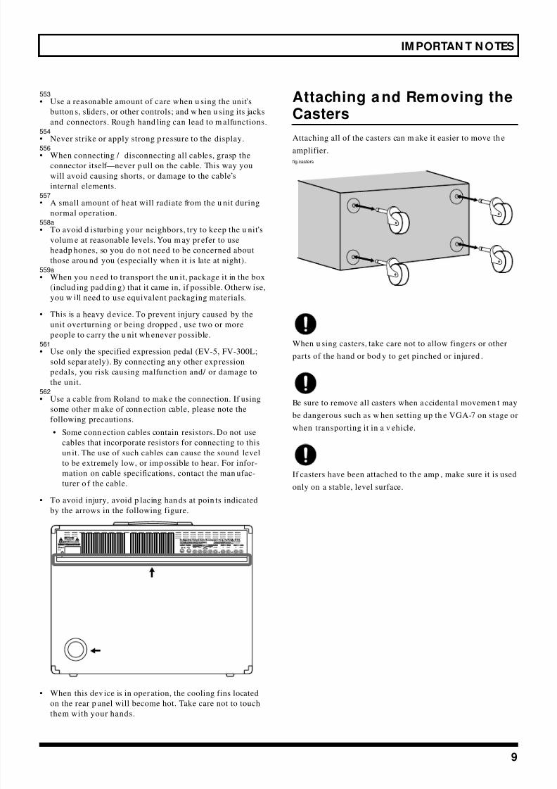
Attaching and Removing theCasters
Attaching all of the casters can m ake it easier to move th eamplifier.
fig.casters
When u sing casters, take care not to allow fingers or other
parts of the hand or bod y to get pinched or injured .
Be sure to remove all casters when a ccidenta l movemen t may
be dangerous such as w hen setting up th e VGA-7 on stage or
when transporting it in a v ehicle.
If casters have been attached to th e amp , make sure it is used
only on a stable, level surface.

8/3/2019 VGA-7 Guitar Amplifier User's Manual
http://slidepdf.com/reader/full/vga-7-guitar-amplifier-users-manual 10/56
10
Basic Opration
* For details on each function, refer to p. 14 and following.
fig.01-1
Pow er Sw itchTurns the pow er on/ off.
M anual ButtonBy pressing the Manual button,
you can play using the sound of
the current knob settings, as on a
conventional guitar amplifier.
GK INUse the sp ecial cable to connect the
GK-2A-compatible guitar (or the
guitar in which the GK-2A is
installed).
When the GK cable is connected or
disconnected, the indicators of the
COSM guitar section w ill blink.You can u se all functions of the
COSM guitar, COSM amplifier,
and EFFECTS.
INPUT JacksConnect a conventional guitar.
You can use th e functions of the
COSM amplifier and EFFECTS.
Effect On/ Off ButtonsSwitch the effects on/ off.
When on, the button indicator will light.
Function select buttonsPress a button to select the desired function.

8/3/2019 VGA-7 Guitar Amplifier User's Manual
http://slidepdf.com/reader/full/vga-7-guitar-amplifier-users-manual 11/56
11
Basic Opration
VARIATION Function
In add ition to the settings, there are several other choices of COSM guitar type an d tu ning, COSM amplifier and speaker, and
EFFECTS delay, choru s and reverb.
* is printed top or under buttons (that the arrow in the picture below should indicate) for which variation settings (types) are
provided.
fig.01-2
The plate on the u pp er left of the cabinet pr ovides a list of variations.
fig.02
Selecting variations
1 . Press the button that “ ” is printed, then
preselect the variation setting to w hich you w ant to
change.
2 . Press [VARIATION/ EDIT], getting its ind icator to light.
The indicator of the curren tly selected ty pe w ill blink.fig.107
* You can switch the variation setting to the one you want by
pressing [PARAMETERw / v].
3 . Press [SELECT/ VALUEw / v] to select the variation
number.
4 . Once you’ve selected a variation num ber, press
[VARIATION] again, extingu ishing its ind icator.
The indicator of the curren tly selected typ e will light,
thu s finalizing you r selection of a variation.
If you w ant to save the selected variation, carry out th e Writeoperation. (p. 24)
2
2,4
3

8/3/2019 VGA-7 Guitar Amplifier User's Manual
http://slidepdf.com/reader/full/vga-7-guitar-amplifier-users-manual 12/56
12
Basic Opration
fig.01-3
Preparations for using the VGA-7
Attaching the GK-2A to yourguitar
First, attach the GK-2A divided pickup (sold sep arately) to
your guitar.
To learn how, refer to the owner’s man ua l for the GK-2A.
The GK-2A cannot be used w ith the follow ingtypes of guitar.
(When a ttached to one of these guita rs, theGK-2 A w ill not function correctly.)
• Guitars with u nconventional string structures, such as
twelve-string guitars or pedal steel guitars
• Guitars that use nylon or gu t strings
• Bass gu itars
• Other guitars that, for structural reasons, have no
location wh ere the GK-2A divided pickup can be
attached correctly
About the GK-2A select sw itch
SYNTH: Select this if you ar e using a GK-2A d ivided
pickup
MIX: When combining the GK-2A d ivided pickup
with the norm al pickup of the guitar
GUITAR: When using the norm al pickup of the guitar
If you w on’t be connecting the jack of the gu itar to thenorm al guitar inp ut jack of the GK-2A, make sure to set the
GK-2A select sw itch to th e SYNTH position.
If this is set to MIX or GUITAR, noise or h um may occur.
About the SYN TH VOL knob ofthe GK-2A
This controls the volu me of the COSM guitar.
TUN ER FunctionAllows you to tune your
guitar.
GK settingThese settings are made for a guitar
on which the GK-2A is installed, or
for a GK-2A-comp atible guitar th at is
to be connected to GK IN.
System settingAllows settings for tuner, noise
sup pressor, foot sw itch, expressionpedal, and MIDI to be made.
W RITEUse this to store settings.
PROGRAM FunctionThe VGA-7 contains 80 preset patches and 80 user
patches.
Use [BANK w / v] and [NUMBER w / v] to select the
desired patch.

8/3/2019 VGA-7 Guitar Amplifier User's Manual
http://slidepdf.com/reader/full/vga-7-guitar-amplifier-users-manual 13/56
13
M aking Connections
You w ill need a guitar on wh ich the GK-2A has been
installed, or a GK comp atible guitar.
The following equipment will add additional functionality to
your VGA-7 system.• MIDI Foot Controller (sold separately: Roland FC-200)
• Expression Pedal (sold separately: Roland EV-5, BOSS
FV-300L)
• Foot Switch (sold separa tely: BOSS FS-5U/ FS-5L)
* Use only the specified expression pedal (EV-5 or BOSS FV-
300L; sold separately). By connecting any other expression
pedals, you risk causing malfunction and/or damage to the unit.
* Use an FS-5U (momentary type) foot switch to change program numbers.
After you have prep ared your gu itar — by installing the GK-
2A — connect your equipment as shown in the following
diagram.
* To prevent m alfunction and/or damage to speakers or other
devices, always turn down the volume, and turn off the power
on all devices before making any connections.
fig.03
Turning the Pow er On and Off
Once the connections have been comp leted, turn on pow er to
your v arious d evices in the ord er specified. By turn ing on
devices in the wrong order, you risk causing malfunction
and/ or damage to speakers and other devices.
External devices (except for outpu t dev ices)→VGA-7→
outpu t devices
* When the power is turned on, the last-selected patch number
or Manual mode (p. 24) will be selected.
* When this device is in operation, the cooling fins located on the
rear panel will become hot. Take care not to touch them with
your hands.
* This unit is equipped with a protection circuit. A brief interval
after power up is required before the unit will operate normally.
* Turn the volume down before you turn the power on or off.
Even if the volume is turned down, some extraneous sound
may be heard when turning the power on/off, but this is not a
malfunction.
S Y N T H V O L
D O W N / S 1 U P / S 2
MIDI Sequencer etc.
External Sound Module(Guitar synthesizer etc.)
Mixer
Guitar withGK-2A
orother GK-2A
compatible guitar
ConventionalGuitar
StereoHeadphones
Foot Switch (BOSS FS-5U/FS-5L etc.)
Expression Pedal(Roland EV-5,BOSS FV-300L etc.)
MIDI Foot Controller(FC-200 etc.)
* When using the FS-5L, only effect on/off can be controlled. (p. 36)
8/3/2019 VGA-7 Guitar Amplifier User's Manual
http://slidepdf.com/reader/full/vga-7-guitar-amplifier-users-manual 14/56
14
Make settings for the divided pickup
The sound quality of the VGA-7 is dramatically affected by how the divided pickup is installed. In order to minimize tonal
irregularity du e to variations in installation, you m ust inpu t the m anner in w hich the divided pickup is installed (divided pickup
settings).
When playing the VGA-7, divided pickup settings are extremely important to the final sound quality.
You must be sure to set these parameters correctly.
Redo the settings when you change the guitar you are using.
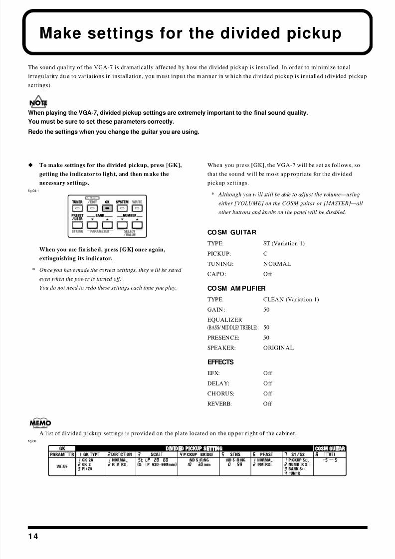
x To make settings for the divided pickup, press [GK],
getting the indicator to light, and then m ake the
necessary settings.
fig.04-1
When you are fin ished, press [GK] once again,
extinguishing its indicator.
* Once you have made the correct settings, they will be saved
even when the power is turned off.
You do not need to redo these settings each time you play.
When you press [GK], the VGA-7 will be set as follows, so
that the sound will be most app ropriate for the divided
pickup settings.
* Although you will still be able to adjust the volume—usingeither [VOLUME] on the COSM guitar or [MASTER]—all
other buttons and knobs on the panel will be disabled.
COSM GUITAR
TYPE: ST (Variation 1)
PICKUP: C
TUNING: NORMAL
CAPO: Off
COSM AM PLIFIER
TYPE: CLEAN (Variation 1)
GAIN: 50
EQUALIZER
(BASS/ MIDDLE/ TREBLE): 50
PRESENCE: 50
SPEAKER: ORIGINAL
EFFECTS
EFX: Off
DELAY: Off
CHORUS: Off
REVERB: Off
A list of divided p ickup settings is provided on the plate located on the up per right of the cabinet.
fig.80

8/3/2019 VGA-7 Guitar Amplifier User's Manual
http://slidepdf.com/reader/full/vga-7-guitar-amplifier-users-manual 15/56
15
Make settings for the divided pickup
Specify the pickup type(1 GK TYPE)
* With the factory settings, this is set to “1 GK-2A.”
1 . Press [PARAMETERw / v] until “1” is shown (blink) at
the left side of the d isplay.
This selects “1 GK TYPE.”
fig.04-2
2 . Press [SELECT/ VALUEw / v] to select the desired
pickup type.
The corresponding nu mber w ill appear in the right of
the d isplay.
* The example display shows that “1 GK-2A” has been selected.
* A piezo-type pickup uses a piezo-electric sensor attached to the
bridge of the guitar to detect the vibrations of the strings.
Specify the direction in w hich thepickup is attached (2 DIRECTION)
* With the factory settings, this is set to “1 NORMAL.”
1. Press [PARAMETERw / v] until “2” is shown (blink) at
the left of the d isplay.
This selects “2 DIRECTION.”
fig.05
2. Press [SELECT/ VALUEw / v] to select th e d irection in
wh ich the d ivided pickup is installed.
The corresponding nu mber w ill appear in the right of
the display.
* The example display shows that “1 NORM AL” has been
selected.
fig.86
Display Setting
1 GK-2A: Make this setting if you are
using a GK-2A.
2 GK-2: Make this setting if you are
using a GK-2.
3 PIEZO: Make this setting if you are
using a piezo divided pickup.
1 2
Display Setting
1 NORMAL: In this d irection, the cable
exits on the side o f string 6.
2 REVERSE: In this d irection, the cable
exits on the side o f string 1.
1 2
NORMAL
REVERSE
string 6 string 1
8/3/2019 VGA-7 Guitar Amplifier User's Manual
http://slidepdf.com/reader/full/vga-7-guitar-amplifier-users-manual 16/56
16
Make settings for the divided pickup
Specify the scale length(3 SCALE)
* With the factory settings, this is set to “ .”
When playing the VGA-7, the scale length setting is
extremely important to the final sound quality.
You must be sure to set this parameter correctly.
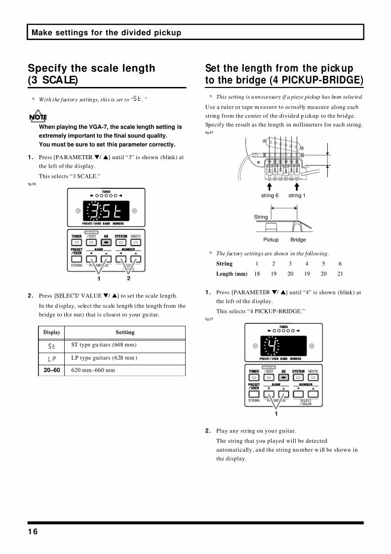
1 . Press [PARAMETERw / v] until “3” is shown (blink) at
the left of the d isplay.
This selects “3 SCALE.”
fig.06
2 . Press [SELECT/ VALUEw / v] to set the scale length.
In the d isplay, select the scale length (the length from the
bridge to th e nut) that is closest to your gu itar.
Set the length from the pickupto the bridge (4 PICKUP-BRIDGE)
* This setting is unnecessary if a piezo pickup has been selected.
Use a ruler or tape m easure to actually measure along each
string from the center of the divided p ickup to the bridge.
Specify the result as the length in millimeters for each string.
fig.87
* The factory settings are shown in the following.
String 1 2 3 4 5 6
Length (mm) 18 19 20 19 20 21
1. Press [PARAMETERw / v] until “4” is shown (blink) at
the left of the d isplay.
This selects “4 PICKUP-BRIDGE.”
fig.07
2. Play any string on you r guitar.
The string that you played will be detected
automatically, and the string nu mber w ill be shown in
the display.
Display Setting
ST type gu itars (648 mm)
LP type guitars (628 mm )
20 –60 620 mm–660 mm
1 2
string 6 string 1
BridgePickup
String
1

8/3/2019 VGA-7 Guitar Amplifier User's Manual
http://slidepdf.com/reader/full/vga-7-guitar-amplifier-users-manual 17/56
17
Make settings for the divided pickup
3 . Use [SELECT/ VALUEw / v] to specify the d istance for
the selected string n um ber.
* The example display shows that the 6th string is at a distance
of 10 mm.
fig.08
4 . Repeat steps 2–3 for each of the rem aining strings.
Adjusting the Pickup Sensitivityfor Each String (5 SEN S)
Adjust the p ickup sensitivity for each string according tohow the GK-2A divided p ickup was installed.
* With the factory settings, this is set to “65.”
Make sure to set the divided pickup select switch to the
“SYNTH ” position.
1. Press [PARAMETERw / v] until “5” is shown (blink) at
the left of the d isplay.
This selects “5 SENS.”
fig.10
2. Play any string on you r guitar.
The string you played will be detected automatically,
and the string nu mber will appear in the display.
At the sam e time, the TUNER indicator w ill show the
level. The ind icators will light from left to right,
corresponding to the strength w ith which you played the
string.
* If you play the string too week or the pickup sensitiv ity is set
too low, the string number may not appear in the display.fig.11-1
Display Setting
10 –30 10–30 mm
You can press [STRING] to sp ecify the string n um ber
directly.
Each press of the bu tton takes you to the next string
num ber, from string 1 throu gh string 6.
(The string number is indicated by a dot.)
If you p lay a string other than the on e indicated by the
dot, the d isplay switches to the num ber of the string that
was played.
3
1
8/3/2019 VGA-7 Guitar Amplifier User's Manual
http://slidepdf.com/reader/full/vga-7-guitar-amplifier-users-manual 18/56
18
Make settings for the divided pickup
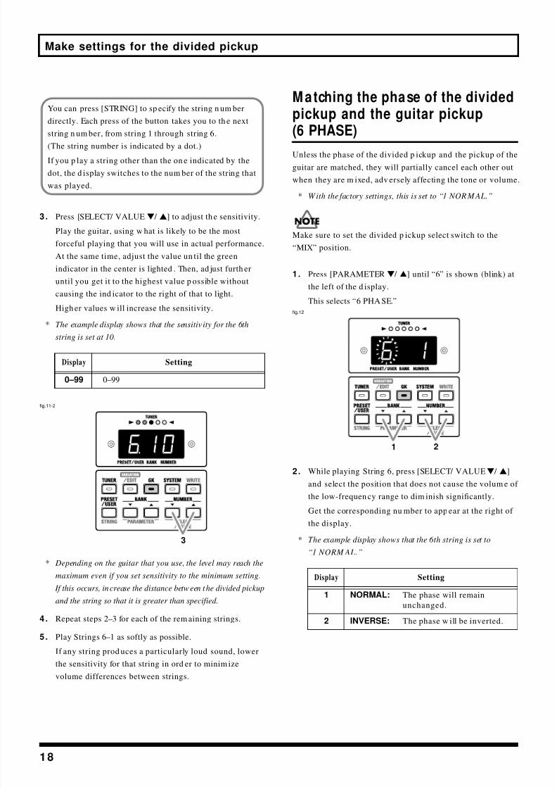
3 . Press [SELECT/ VALUEw / v] to adjust th e sensitivity.
Play the guitar, using w hat is likely to be the most
forceful playing that you will use in actual performance.
At the same time, adjust the value un til the green
indicator in the center is lighted . Then, ad just furth er
until you get it to the highest value p ossible without
causing the ind icator to the right of that to light.
High er values w ill increase the sensitivity.
* The example display shows that the sensitiv ity for the 6th
string is set at 10.
fig.11-2
* Depending on the guitar that you use, the level may reach the
maximum even if you set sensitivity to the minimum setting.
If this occurs, increase the distance between the divided pickup
and the string so that it is greater than specified.
4 . Repeat steps 2–3 for each of the rem aining strings.
5 . Play Strings 6–1 as softly as possible.
If any string prod uces a particularly loud sound, lower
the sensitivity for that string in ord er to minim ize
volume differences between strings.
M atching the phase of the dividedpickup and the guitar pickup
(6 PHASE)Unless the phase of the divided p ickup and the pickup of the
guitar are matched, they will partially cancel each other out
when they are m ixed, adv ersely affecting the tone or volume.
* With the factory settings, this is set to “1 NORMAL.”
Make sure to set the divided p ickup select switch to the
“MIX” position.
1. Press [PARAMETERw / v] until “6” is shown (blink) atthe left of the d isplay.
This selects “6 PHA SE.”
fig.12
2. While playing String 6, press [SELECT/ VALUEw / v]
and select the position that does not cause the volum e of
the low-frequen cy range to dim inish significantly.
Get the corresponding nu mber to app ear at the right of
the display.
* The example display shows that the 6th string is set to
“1 NORM AL.”
Display Setting
0 –99 0–99
You can press [STRING] to sp ecify the string n um ber
directly. Each press of the button takes you to th e next
string n um ber, from string 1 through string 6.
(The string number is indicated by a dot.)
If you p lay a string other than the on e indicated by the
dot, the d isplay switches to the num ber of the string that
was played.
3
Display Setting
1 NORMAL: The phase will remain
unchanged.
2 INVERSE: The phase w ill be inverted.
1 2

8/3/2019 VGA-7 Guitar Amplifier User's Manual
http://slidepdf.com/reader/full/vga-7-guitar-amplifier-users-manual 19/56
19
Make settings for the divided pickup
Specify the function of theS1 / S2 sw itch (7 S1 / S2)
* With t he factory settings, this is set to “1 PICKUP SEL.”
1 . Press [PARAMETERw / v] until “7” is shown (blink) at
the left of the d isplay.
This selects “7 S1/ S2.”
fig.13
2 . Use [SELECT/ VALUEw / v] to specify the function of
the S1/ S2 switches.
Get the corresponding nu mber to app ear at the right of
the d isplay.
* The S1/S2 switch is disabled while settings are being made.
* The example display shows that the S1/S2 switch is set t o
“1 PICKUP SEL.”
Cha nging the Sw itching Direction of S1 a nd S2w hen PICKUP SEL Is Selected
Nor mally, the COSM GUITAR pickup s are switched by
pressing th e S1 switch for MIC→ F, and pressing th e S2
switch for F→MIC, but by sw itching on the POWER
switch wh ile hold ing dow n [GK] and [NUMBERv], you
can set this so the directions are reversed . In this case,
the CO SM GUITAR PICKUP “R” indicator w ill blink.
To return to the ordinary state, switch on the POWER
while holding down [GK] and [NUMBER w].In this case, the COSM GUITAR PICKUP “F” indicator
will blink.
Setting the Output Level ofthe COSM Guitar (8 LEVEL)
You can ad just the balance between th e outp ut level of thedivided p ickup and th e outpu t level of the guitar pickup .
* With the factory settings, this is set to “0.”
Make sure to set the divided pickup select switch to the
“SYNTH” position.
1. Press [PARAMETERw / v] until “8” is shown (blink) at
the left of the d isplay.
This selects “8 LEVEL.”
fig.14
2. Press [SELECT/ VALUEw / v] to adjust the balan ce
(– 5–5) between the COSM guitar sound and the normal
guitar sound.
Negative (–) settings will decrease the COSM guitar
soun d, and positive (+) settings will increase it.
Move the select switch of the divided pickup betw een
“SYNTH” an d “GUITAR,” and ad just the volum e
balance while playing you r instrument in each position.
Display Setting
1 PICKUP SEL: Switching the pickup of
COSM guitar
2 NUMBER: Number up/ down
3 BANK: Bank up/ down
4 TUNER: Tuner on/ off
1 2
1 2
8/3/2019 VGA-7 Guitar Amplifier User's Manual
http://slidepdf.com/reader/full/vga-7-guitar-amplifier-users-manual 20/56
20
TUN ER
Here’s how to u se the VGA-7’s tuner function to tun e your gu itar.
In order to u se the tuner, you m ust first make tu ner settings.
Setting the Tuner
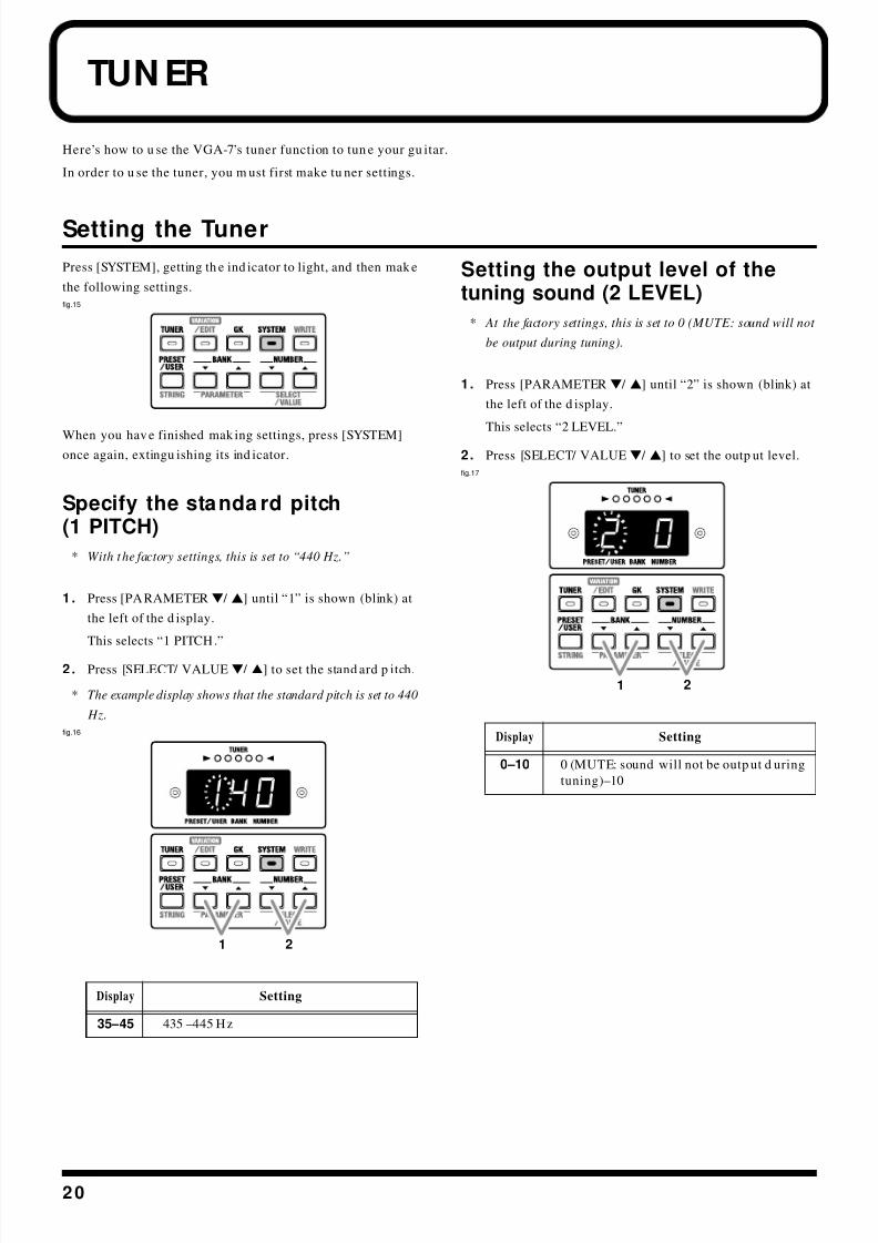
Press [SYSTEM], getting th e ind icator to light, and then mak e
the following settings.
fig.15
When you hav e finished mak ing settings, press [SYSTEM]once again, extingu ishing its ind icator.
Specify the standa rd pitch(1 PITCH)
* With the factory settings, this is set to “440 Hz.”
1 . Press [PARAMETERw / v] until “1” is shown (blink) at
the left of the d isplay.
This selects “1 PITCH.”
2 . Press [SELECT/ VALUEw / v] to set the stand ard p itch.
* The example display shows that the standard pitch is set to 440
Hz.
fig.16
Setting the output level of thetuning sound (2 LEVEL)
* At the factory settings, this is set to 0 (MUTE: sound will not
be output during tuning).
1. Press [PARAMETERw / v] until “2” is shown (blink) at
the left of the d isplay.
This selects “2 LEVEL.”
2. Press [SELECT/ VALUEw / v] to set the outp ut level.
fig.17
Display Setting
35 –45 435 –445 Hz
1 2
Display Setting
0 –10 0 (MUTE: sound will not be outp ut d uring
tuning)–10
1 2

8/3/2019 VGA-7 Guitar Amplifier User's Manual
http://slidepdf.com/reader/full/vga-7-guitar-amplifier-users-manual 21/56
21
TUN ER
Tuning your guitar
* While using the tuner, sound will not be output from the line
out jacks.
1 . Press [TUNER], getting th e ind icator to light.
This turns on the Tuner function.
2 . Play a single unfretted note on the string you w ish to
tune.
The note name closest to the string you played will
app ear in the display.
For a guitar connected to GK IN, the string number will
also be displayed.
* Cleanly play a single note only on the string that you wish totune.
fig.18
3 . Adjust the tuning u ntil the note name of the string you
played app ears in the display.
4 . Tune your gu itar so that only the green indicator in the
center is lit.
5 . Repeat steps 2–4 to tune all the strings.
* When tun ing a guitar that has a tremolo arm, tuning one
string m ay cause the other strings to go out of tun e. In such
cases, first tune the strings to the approximate pitch (so that the note name is displayed), and then keep tuning each string
until they are all in tu ne.
6 . When you have finished tuning, press [TUNER],
extinguishing its indicator.
This turns off the Tuner fun ction.
This symbol
indicates the “#” sign

8/3/2019 VGA-7 Guitar Amplifier User's Manual
http://slidepdf.com/reader/full/vga-7-guitar-amplifier-users-manual 22/56
22
About Patch
When you a re performing on your gu itar, you w ill need a
variety of sound s, depending on the situation.
On the VGA-7, the settings of the panel buttons and knobs
used to create the sound can be remembered as a set, whichis called a Patch.
You can create several patches, and switch between patches
to use the desired tonal character whenever you need.
fig.22
There are two types of patches.
Preset Patches
These are 80 patches p rovided by the VGA-7. They contain a
wide ran ge of sound s approp riate for various situations.
After selecting one of these patches, you can u se the button s
or knobs to tem porarily modify the settings, but if you tu rn
off the pow er or select another p atch, your mod ifications will
be lost. If you w ish to keep the m odified settings as a patch,
you m ust save the patch as a User Patch.
User Patches
These are original patches tha t you create. You are free to
rew rite and sav e the contents of the settings. Up to 80 user
patches can be created.
Sw itching the Patches
Patches (preset/ user) are selected by specifying the bank (0–
7) and num ber (1–10).fig.23
1. Press [PRESET/ USER] to select the Preset Patches (P) or
the User Pa tches (U).
2. Press [BANKw / v] to select the Banks (0–7).
3. Press [NUMBERw / v] to select the Nu mber (1–10).
• When th e num ber is 10, the d isplay will ind icate “0.”.
You can use a foot switch to switch the bank/ num ber.
(p. 36)
Direct Number Button
You can u se the Direct Num ber button to directly access and
select numbers in the currently selected bank.
fig.24
• If you p ress [A/ B], extinguishing the ind icator,
these buttons will select numbers 1–5.
• If you p ress [A/ B], getting the ind icator to light,
these buttons will select numbers 6–10.
COSM Guitar
COSM Amplifier
P70.
EffectsCOSM Guitar
COSM Amplifier
P01
Effects
Preset Patch80 patches
COSM Guitar
COSM Amplifier
U70.
EffectsCOSM Guitar
COSM Amplifier
U01
Effects
User Patch80 patches
0
1
2
3
4
5
6
7
1
01
11
21
31
41
51
61
71
2
02
12
22
32
42
52
62
72
3
03
13
23
33
43
53
63
73
4
04
14
24
34
44
54
64
74
6
06
16
26
36
46
56
66
76
5
05
15
25
35
45
55
65
75
7
07
17
27
37
47
57
67
77
8
08
18
28
38
48
58
68
78
9
09
19
29
39
49
59
69
79
10
00.
10.
20.
30.
40.
50.
60.
70.
8/3/2019 VGA-7 Guitar Amplifier User's Manual
http://slidepdf.com/reader/full/vga-7-guitar-amplifier-users-manual 23/56
23
About Patch
Changing Patch Settings
Use the buttons and knobs to mod ify the settings of the
selected patch. This op eration is called “Editing.”
q Immediately after changing patches, the settings stored
in the patch will not match the positions of the knobs.
When you tu rn the knob, the setting value stored in the
patch w ill be shown in the d isplay. Once the position of
the knob m atches the displayed v alue, the displayed
value will begin to change.
When you change th e setting of a knob, it is a good id ea
to rotate the kn ob all the way to the righ t or left before
you begin ad justing the value.
q When you mod ify the settings stored in a p atch, the
direct number bu tton for the current patch w ill blink.
This indicates that the current patch is being edited.
Selecting variations
For the COSM guitar type and tuning, COSM amplifier type
and speaker, and EFFECTS delay, chorus an d rev erb, there
are several variations in add ition to the settings (types).
* is prin ted top or under bu ttons for which variat ion
settings (types) are provided.
A list of variations is prov ided on the p late located on
the top left of the cabinet. (p. 11)
fig.20
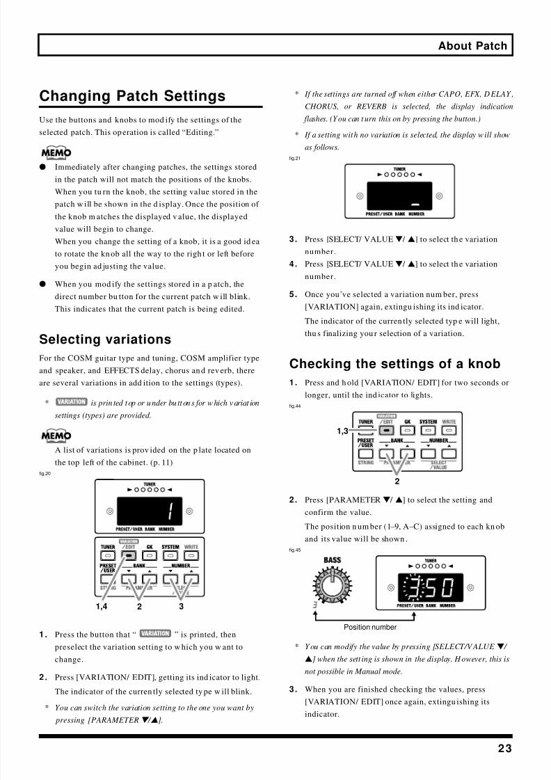
1 . Press the button that “ ” is printed, then
preselect the variation setting to w hich you w ant to
change.
2 . Press [VARIATION/ EDIT], getting its ind icator to light.
The indicator of the curren tly selected ty pe w ill blink.
* You can switch the variation setting to the one you want by
pressing [PARAMETERw / v].
* If the settings are turned off when either CAPO, EFX, DELAY ,
CHORUS, or REVERB is selected, the display indication
flashes. (You can t urn this on by pressing the button.)
* If a setting with no variation is selected, the display will showas follows.
fig.21
3. Press [SELECT/ VALUEw / v] to select th e variation
number.
4. Press [SELECT/ VALUEw / v] to select th e variation
number.
5. Once you’ve selected a variation num ber, press
[VARIATION] again, extingu ishing its ind icator.
The indicator of the curren tly selected typ e will light,
thu s finalizing you r selection of a variation.
Checking the settings of a knob
1. Press and h old [VARIATION/ EDIT] for two seconds or
longer, until the ind icator to lights.
fig.44
2. Press [PARAMETERw / v] to select the setting and
confirm the value.
The position n um ber (1–9, A–C) assigned to each kn ob
and its value will be shown .
fig.45
* You can modify the value by pressing [SELECT/VALUE w /
v] when the sett ing is shown in the display. However, this is
not possible in Manual mode.
3. When you are finished checking the values, press
[VARIATION/ EDIT] once again, extingu ishing its
indicator.
2 31,4
2
1,3
Position number

8/3/2019 VGA-7 Guitar Amplifier User's Manual
http://slidepdf.com/reader/full/vga-7-guitar-amplifier-users-manual 24/56
24
About Patch
Saving your modifications ina patch (Write)
If you wish to save th e mod ifications you have mad e, youmu st store them in a u ser patch. This opera tion is called
“Write.”
All settings except for th e MASTER knob can be saved .
* If you used the foot switch to turn the effect on/off (p. 36 ), that
setting will also be remembered.
1 . When you finish m odifying (editing) the settings, press
[WRITE], getting its indicator to blink.
fig.46
2 . Use [BAN Kw / v] and [NU NBERw / v] to select the
user patch in wh ich you r settings will be stored.
* Patch num bers can also be selected using the direct number
buttons.
3 . To write the settings, press [WRITE].
While Write is being executed , the ind icator flashes
rapidly.
When the d ata has been w ritten, the indicator will go
out, and the writing destination u ser patch will be
displayed.
If You W ant to Ca ncel a W rite Operationin Progress
Press either [TUNER], [VARIATION/ EDIT], [GK],
[SYSTEM], or [PRESET/ USER].The values are left as is, and the Write oper ation is
cancelled.
M anual M ode
If you w ish to play the sound specified by the current
settings of the knobs (rather than the sound memorized inthe patch), switch to Manual m ode.
x To select Manual mode, press [MANUAL], lighting its
indicator.
In Manual m ode, the d isplay w ill show the following.
fig.19
After this, when one of the buttons or knobs is used, the
settings for that control appear in the display.
* When the settings for CAPO (p. 27 ) or DELAY TIME (p. 32)
are showing in the display, you can change the settings value
directly by pressing the [SELECT/VALUE w / v].
Press [A/ B] to exit Manual mode an d retu rn to the
settings of the selected p atch.
* The [MA NUA L] indicator will also go out, and Manual mode
will be exited if you press one of the [PRESET/USER],
[BANK w
/ v
], [NUM BERw
/ v
] or Direct Number buttons.
x If you once again enter Manual mode, the previous
settings used in Manual mode are called up (except for
knob settings).
x If you hol d dow n the Di rect Number button that is lit
and press [MANUAL] to select Manual mod e, settings
from the previous patch settings (other than the knob
settings) will remain active.
2
1,3
2
8/3/2019 VGA-7 Guitar Amplifier User's Manual
http://slidepdf.com/reader/full/vga-7-guitar-amplifier-users-manual 25/56
25
Panel Descriptions
Front Panel
In some cases, odd soun ds m ay occur w hen op erating the bu tton or a kn ob, but this does not indicate a malfunction.
COSM Guita r Section (COSM GUITAR)
This analyzes the principal comp onents of an electric guitar,
and precisely simu lates the function of each of the
components.
The number an d typ e of pickup s, the nu mber of strings, the
tuning of each string, and each element that p lays a part in
creating the tone of a guitar is digitally add ed to the
vibration p rodu ced by the strings of your gu itar.
In ad dition, the VGA-7 detects each string’s pitch and
enveloping — th e “shape” of the soun d. These characteristics
are then d igitally app lied to th e current patch’s waveform,
causing it to sound with all of the nuances of your gu itar
performance.
fig.100
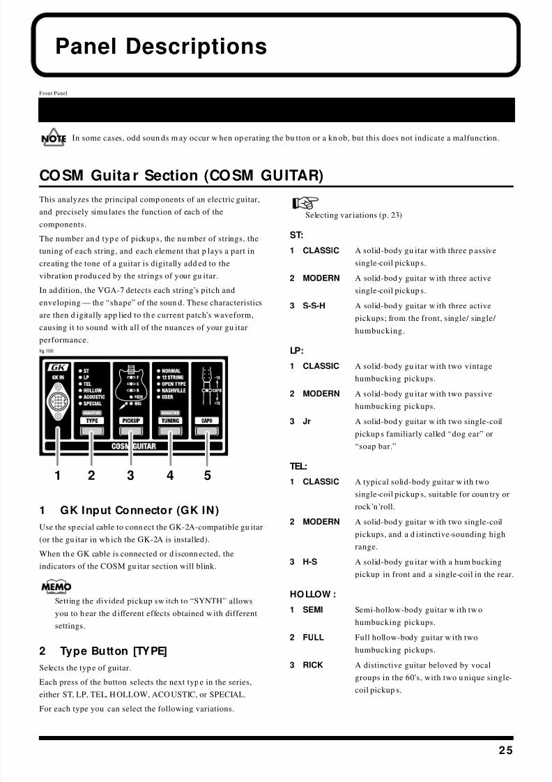
1 GK Input Connector (GK IN)
Use the sp ecial cable to conn ect the GK-2A-compatible gu itar
(or the gu itar in wh ich the GK-2A is installed).
When th e GK cable is connected or d isconn ected, the
indicators of the COSM gu itar section will blink.
Setting the divided pickup sw itch to “SYNTH” allows
you to h ear the d ifferent effects obtained w ith different
settings.
2 Type Button [TYPE]
Selects the typ e of guitar.
Each press of the button selects the next typ e in the series,either ST, LP, TEL, H OLLOW, ACO USTIC, or SPECIAL.
For each type you can select the following variations.
Selecting var iations (p. 23)
ST:
1 CLASSIC A solid-body gu itar with three p assive
single-coil pickup s.
2 MODERN A solid-bod y guitar w ith three active
single-coil pickup s.
3 S-S-H A solid-bod y guitar w ith three active
pickups; from the front, single/ single/
humbucking.
LP:
1 CLASSIC A solid-body gu itar with two vintage
humbucking pickups.
2 MODERN A solid-body gu itar with two passive
humbucking pickups.
3 Jr A solid-bod y guitar w ith two single-coil
pickup s familiarly called “dog ear” or
“soap bar.”
TEL:
1 CLASSIC A typical solid-body guitar w ith two
single-coil pickup s, suitable for coun try or
rock ’n’roll.
2 MODERN A solid-bod y guitar w ith two single-coil
pickups, and a d istinctive-sounding high
range.
3 H-S A solid-body gu itar with a hum bucking
pickup in front and a single-coil in the rear.
HOLLOW :
1 SEMI Semi-hollow-body guitar w ith tw o
humbucking pickups.
2 FULL Full hollow-body guitar w ith two
humbucking pickups.
3 RICK A distinctive guitar beloved by vocal
groups in the 60’s, with two u nique single-
coil pickup s.
Front Panel
1 2 3 4 5
8/3/2019 VGA-7 Guitar Amplifier User's Manual
http://slidepdf.com/reader/full/vga-7-guitar-amplifier-users-manual 26/56
26
Panel Descriptions
ACOUSTIC:
1 STANDARD The acoustic guitar w ith a flat top an d back
2 ROUND The flat top acoustic guitar with a round
back mad e of resin
3 METAL A metal body gu itar with one cone
resonator, su itable for bottle-neck (slide)
playing techniques.
4 NYLON STR Guitars using nylon or gut strings
5 BANJO A plucked string instrument with a skin-
covered bod y.
6 UKULELE A plucked string instrument with a sm all
body and nylon strings.
SPECIAL:
1 BOWED This sound represents stringed mu sical
instruments played with a bow.
2 PIPE This sound is like a soft woodwind lead
instrument.
3 ORGAN Sustained organ-like sound .
4 BRASS Soft brass-like sou nd .
5 SOLO Soft lead sound.
6 SYNTH 1 Synth sound with filter sweep.
7 SYNTH 2 Synth sound with mod ulation.
8 FILTER BASS A sound reminiscent of a bass with filter
applied.
When ACOUSTIC or SPECIAL is selected, setting the
AMP TYPE (p. 28) in the COSM AMP section to “FULL
RANGE” is very effective.
3 Pickup Button [PICKUP]
Depending on the type (variation) of COSM guitar, you can
select the pickup or mic.
* If the COSM guitar type is SPECIAL, the pickup selection is
ignored.
F:
Use the front pickup .
C:
Use the center pickup.
R:
Use the rear pickup .
PIEZO: (type: ACOUSTIC)Use the piezo pickup.
MIC: (type: ACOUSTIC)
Use a hypothetical mike ideal for picking u p th e sound of an
acoustic guitar.
* If either ST, LP, TEL, or HOLLOW is selected, you can select a sett ing in which two pickups are used simultaneously.
F+C: When ST is selected
F+R: When either LP, TEL, or HOLLOW is selected
C+R: When ST is selected
You can u se the S1/ S2 switch to switch pickup s. (p. 19)
4 Tuning Button [TUNING]
You can p erform u sing various tu nings that are set on the
VGA-7, without actually retuning the guitar.
Each time you press the button, the tun ing type w ill
alternate.
* If the COSM guitar type is SPECIAL, tunings other than
NORMAL cannot be selected.
You can select variat ions for 12 STRING, OPEN TYPE, and
NASHVILLE types.
Selecting var iations (p. 23)
NORMAL:
This is the conventiona l tuning in w hich the strings are
pitched starting from the 6th string as E/ A/ D/ G/ B/ E.
12 STRING:
This tuning simu lates the sound of a 12-string guitar.
1 REGULAR A higher octave is added to strings 6–3,
and strings 2 and 1 are doubled at the same
pitch.
2 OCTAVE A higher octave is added to strings 6–1.
3 DETUNE Adds a slight off-pitch sound to theoriginal sound s of strings 6–1.
OPEN TYPE:
A tunin g indispen sable for blues, effective when p layed w ith
a slide bar .
1 OPEN D Starting from the 6th string, the strings w ill
be pitched D, A, D, F#, A, D.
2 OPEN G Starting from the 6th string, the strings w ill
be p itched D, G, D, G, B, D.
3 DROPPED D Only string 6 is lowered a w hole step.
Starting from the 6th string, the strings w ill
be p itched D, A, D, G, B, E.

8/3/2019 VGA-7 Guitar Amplifier User's Manual
http://slidepdf.com/reader/full/vga-7-guitar-amplifier-users-manual 27/56
27
Panel Descriptions
N ASHV ILLE:
1 TYPE 1 Strings 6–3 will be one octave higher.
Strings 2 and 1 will be the original pitch.
2 TYPE 2 Strings 6–4 will be one octave higher.
Strings 3–1 will be the original p itch.
USER:
This is a user-specified tu ning.
Relative to the conven tional tun ing for each string (starting
from the 6th string, E/ A/ D/ G/ B/ E), you can freely specify
the p itch in a range of ± 1 octave.
s Crea ting user settings
1 . Press [TUNING] to se lect USER.
2 . Press [VARIATION/ EDIT], getting its ind icator to light.
The USER indicator will blink to ind icate that you m ay
begin making user settings.
The string number and note name w ill appear in the
display, and the octave setting w ill be shown by the
tuner indicator.
fig.27
The relationship betw een the tuner indicator lights and
the pitch is shown below.
fig.27a
3 . Play any string of your gu itar.
The string that you p layed will be detected au tomatically,
and the string nu mber will appear in the display.
4. Press [SELECT/ VALUEw / v] to specify the note nam e
(pitch) for the string number.
5. Repeat steps 3–4 for each of the rema ining strings.
6. When you have finished making settings, press
[VARIATION/ EDIT], extingu ishing its indicator.
* To save the changes, you must perform a write operation.
(p. 24)
5 Capo Button [CAPO]
This simu lates a capo a ttached to th e neck of the gu itar.
The pitch specified by the tu ning of the COSM guitar can be
shifted in semitone step s over a ran ge of ± 1 octave.
* You can tu rn the Capo function on/off by pressing the
[CAPO]. When on, the indicator will light.
* If the type of COSM guitar is SPECIAL, Capo setting is
ignored.
s Adjusting the amount of pitch shift
1. Press [CAPO], getting th e ind icator to light.
2. Press [VARIATION/ EDIT], getting its ind icator to light.
The capo indicator w ill blink, and th e display w ill show
the amount of pitch shift.
3. Press [SELECT/ VALUEw / v] to specify the amou nt of
pitch sh ift.
Range: -12– -1, 1 – 12
fig.28
4. After making th e setting, press [VARIATION / EDIT]
once again, extingu ishing its ind icator.
When you press [CAPO], the current p itch shift amoun t
will be shown in th e display for several second s. When
the am ount of pitch shift is displayed, you can press
[SELECT/ VALUEw / v] to change it.
* To save the changes, you must perform a write operation.
(p. 24)
In tune with the standard pitch
Pitch one octave upPitch one octave down
Pitch higher thanstandard pitch
Pitch lower thanstandard pitch
You can press [STRING] to sp ecify the string n um ber
directly.
Each press of the bu tton takes you to the next string
num ber, from string 1 throu gh string 6.
(The string number is indicated by a dot.)
If you p lay a string other than the on e indicated by the
dot, the d isplay switches to the num ber of the string that
was played.
8/3/2019 VGA-7 Guitar Amplifier User's Manual
http://slidepdf.com/reader/full/vga-7-guitar-amplifier-users-manual 28/56
28
Panel Descriptions
COSM Amplifier Section (COSM AM PLIFIER)
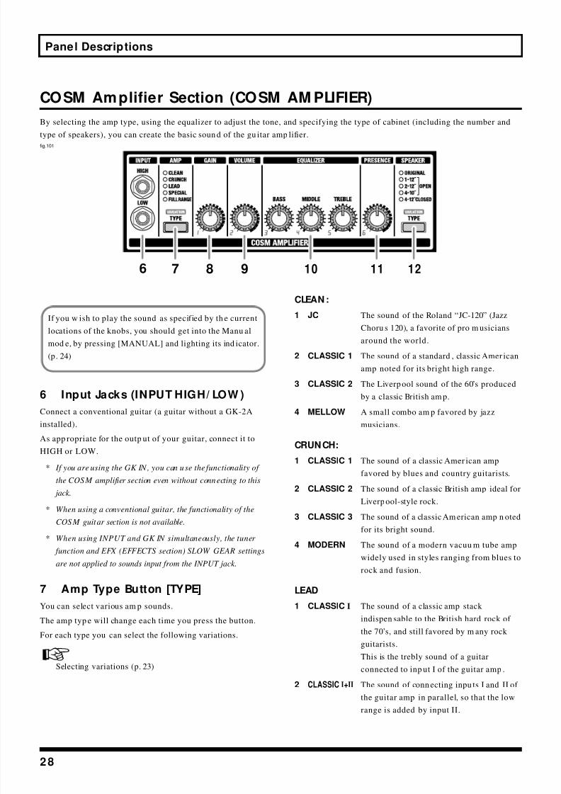
By selecting the amp type, using the equalizer to adjust the tone, and specifying the type of cabinet (including the number and
type of speakers), you can create the basic soun d of the gu itar amp lifier.fig.101
6 Input Jacks (INPUT HIGH/ LOW )
Connect a conventional guitar (a guitar without a GK-2A
installed).
As app ropriate for the outp ut of your guitar, connect it to
HIGH or LOW.
* If you are using the GK IN, you can use the functionality of
the COSM amplifier section even without connecting to this
jack.
* When using a conventional guitar, the functionality of the
COSM guitar section is not available.
* When using INPUT and GK IN simultaneously, the tuner
function and EFX (EFFECTS section) SLOW GEAR settings
are not applied to sounds input from the INPUT jack.
7 Amp Type Button [TYPE]
You can select various am p sounds.
The amp typ e will change each time you press the button.
For each type you can select the following variations.
Selecting variations (p. 23)
CLEAN :
1 JC The sound of the Roland “JC-120” (Jazz
Choru s 120), a favorite of pro m usicians
around the world.
2 CLASSIC 1 The sound of a standard , classic Amer ican
amp noted for its bright high range.
3 CLASSIC 2 The Liverp ool sound of the 60’s produced
by a classic British am p.
4 MELLOW A small combo am p favored by jazz
musicians.
CRUNCH:
1 CLASSIC 1 The sound of a classic Amer ican amp
favored by blues and country guitarists.
2 CLASSIC 2 The sound of a classic British amp ideal for
Liverp ool-style rock.
3 CLASSIC 3 The sound of a classic Am erican amp n oted
for its bright sound.
4 MODERN The sound of a modern vacuu m tube amp
widely used in styles ranging from blues to
rock and fusion.
LEAD
1 CLASSIC I The sound of a classic amp stack
indispen sable to the British hard rock of
the 70’s, and still favored by m any rock
guitarists.
This is the trebly sound of a guitar
connected to inp ut I of the guitar amp .
2 CLASSIC I+II The sound of conn ecting inpu ts I and II of
the guitar amp in parallel, so that the low
range is added by input II.
6 7 8 9 10 11 12
If you w ish to play the sound as specified by th e current
locations of the knobs, you should get into the Manu al
mod e, by pressing [MANUAL] and lighting its ind icator.
(p. 24)
8/3/2019 VGA-7 Guitar Amplifier User's Manual
http://slidepdf.com/reader/full/vga-7-guitar-amplifier-users-manual 29/56
29
Panel Descriptions
3 MODERN 1 The sound of a tube am p typ ical of the late
‘70s to 80s, characterized by a d istinctive
mid-range.
4 MODERN 2 A tube amp sound with versatiledistortion, usable in a wid e range of styles.
5 METAL 1 The sound of a vacuu m tu be amp stack for
heavy metal.
6 METAL2 A high gain and p owerful metal sound .
SPECIAL:
1 LAYER 1 The layered sound of two different amp s
used simultaneously, produ ced by a
combination of a clean tone (line) and a
drive tone.
When the GK input is used, the sound of
the COSM guitar section w ill be the clean
tone, and the sound of the normal guitar
will be the drive tone. If using th e divided
pickup , set the select switch to the “MIX”
position.
2 LAYER 2 The layered sound of two different amp s
used simultaneously, produ ced by a
combination of a clean tone (guitar amp )
and d rive tone.
When the GK input is used, the sound of
the COSM guitar section w ill be the clean
tone, and the sound of the normal guitar
will be the drive tone. If using th e divided
pickup , set the select switch to the “MIX”
position.
3 FUZZ The fuzz sou nd of a transistor amp, w ith
unique h armonic content qu ite unlike the
distortion of a vacuu m tube am p.
* When LAY ER 1 or LAYER 2 is selected, the WAH, SLOW
GEAR, and COM PRESSOR effects are not operational with
the GK-2A switch set to “SYNTH.”
You can u se LAYER to get p erforman ces with a layered
sound, for example, with one guitar using an acoustic
guitar (in the COSM GUITAR settings) with a d rive tone
(norma l guitar sou nd setting in COSM AMPLIFIER).
* Control the volume balance between the COSM guitar and the
normal guitar by adjusting the COSM guitar setting
“8 LEVEL.” (p. 19)
FULL RAN GE:
1 FLAT This amp h as a flat respon se that is ideal
for use w ith COSM guitar ty pes SPECIAL
or ACOUSTIC.
2 SHAPED A transparent soun d, ideal for chording on
an electric-acoustic guitar.
3 FAT A sound with a distinctively rich mid- and
low-range.
8 Ga in Knob [GAIN ]
Adjusts the inpu t gain of the amp.
Range: 0–99
9 Volume Knob [VOLUME]Adjusts the volume. It is convenient to use the volume knob
when adjusting the volume betw een patches.
Range: 0–99
10 Equalizer (EQUALIZER)
This is a three-band type equ alizer. The tone of each ran ge
will be adjusted according to the amp type.
Bass Knob [BASS]
Adjusts the low frequency range tone.
Range: 0–99
M iddle Knob [MIDDLE]
Adjusts the tone for the midd le frequency range.
Range: 0–99
Treble Knob [TREBLE]
Adjusts the high frequency range tone.
Range: 0–99
* Depending on the amp type, there may be no sound if you set
[BASS], [MIDDLE], and [TREBLE] all to values of 0.
11 Presence Knob [PRESEN CE]
Adjusts the definition of the soun d.
Range: 0–99
12 Speaker Type Button [TYPE]
You can select the speaker size and cabinet shap e.
The type will change each time you press the button.
You can select a variation for each typ e other th anORIGINAL.
Selecting var iations (p. 23)
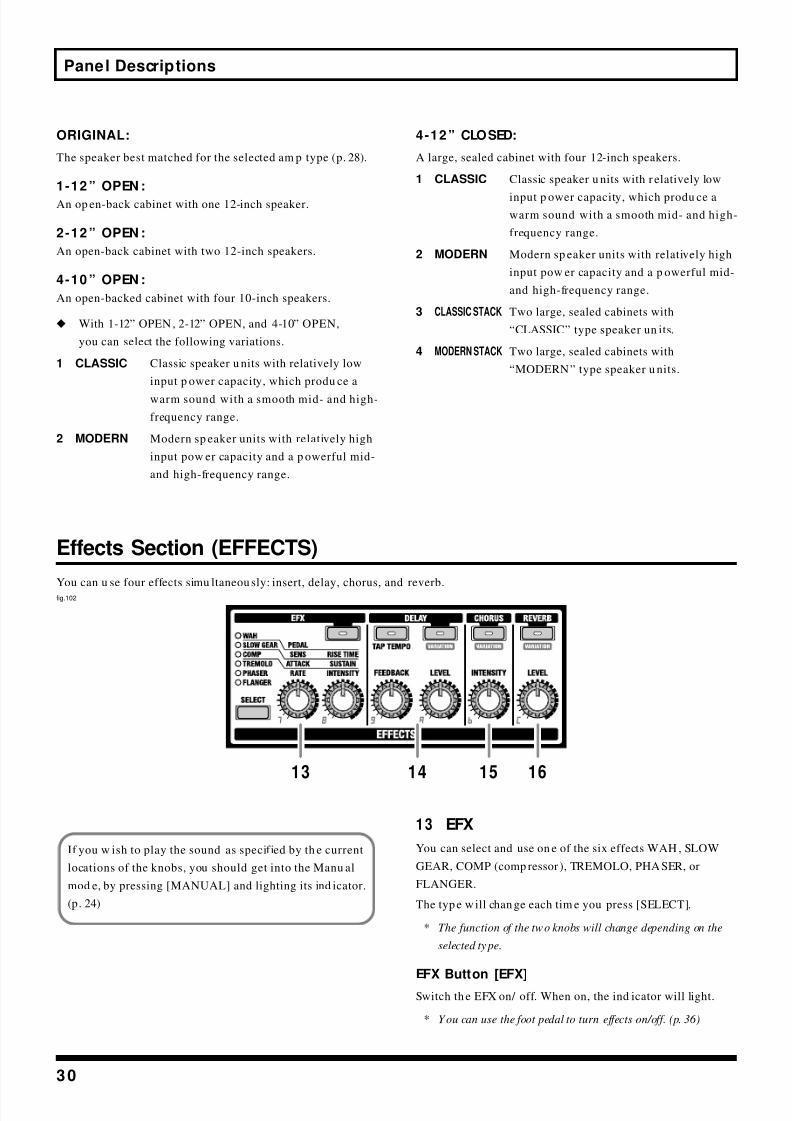
8/3/2019 VGA-7 Guitar Amplifier User's Manual
http://slidepdf.com/reader/full/vga-7-guitar-amplifier-users-manual 30/56
30
Panel Descriptions
ORIGINAL:
The speaker best matched for the selected am p type (p. 28).
1-12 ” OPEN :
An op en-back cabinet with one 12-inch speaker.
2-12 ” OPEN :
An open-back cabinet with two 12-inch speakers.
4-10 ” OPEN :
An open-backed cabinet with four 10-inch speakers.
x With 1-12” OPEN , 2-12” OPEN, and 4-10” OPEN,
you can select the following variations.
1 CLASSIC Classic speaker u nits with relatively low
input p ower capacity, which produ ce a
warm sound with a smooth mid- and high-
frequency range.
2 MODERN Modern sp eaker units with relatively high
input pow er capacity and a p owerful mid-
and high-frequency range.
4-12” CLOSED:
A large, sealed cabinet with four 12-inch speakers.
1 CLASSIC Classic speaker u nits with r elatively low
input p ower capacity, which produ ce a
warm sound with a smooth mid- and high-
frequency range.
2 MODERN Modern sp eaker units with relatively high
input pow er capacity and a p owerful mid-
and high-frequency range.
3 CLASSIC STACK Two large, sealed cabinets with
“CLASSIC” type speaker un its.
4 MODERN STACK Two large, sealed cabinets with
“MODERN” type speaker u nits.
Effects Section (EFFECTS)
You can u se four effects simu ltaneou sly: insert, delay, chorus, and reverb.
fig.102
13 EFX
You can select and use on e of the six effects WAH , SLOW
GEAR, COMP (comp ressor ), TREMOLO, PHASER, or
FLANGER.
The typ e w ill chan ge each tim e you press [SELECT].
* The function of the two knobs will change depending on the
selected ty pe.
EFX Button [EFX]
Switch th e EFX on/ off. When on, the ind icator will light.
* You can use the foot pedal to turn effects on/off. (p. 36 )
13 14 15 16
If you w ish to play the sound as specified by th e current
locations of the knobs, you should get into the Manu al
mod e, by pressing [MANUAL] and lighting its ind icator.
(p. 24)

8/3/2019 VGA-7 Guitar Amplifier User's Manual
http://slidepdf.com/reader/full/vga-7-guitar-amplifier-users-manual 31/56
31
Panel Descriptions
q W AH
This effect creates a uniqu e tone by changin g the frequen cy
respon se of a filter. By connecting a sepa rately ava ilable
expr ession p edal (e.g., Roland EV-5 or BOSS FV-300L) youcan control the w ah effect in real time.
* While using W AH , the expression pedal cannot be used to
control the volume.
fig.30
Peda l Knob [PEDAL]
This simu lates the ped al position when th e wah pedal is
operated.
Rotating the knob fully clockw ise will adv ance the ped al all
the w ay. Rotating the kn ob fully counterclockwise will return
the ped al all the way.
Range: 0–99
q SLOW GEARSlow Gear is an effect that fad es-in ea ch note (violin-style
playing) by d etecting the picking of the guitar. It lowers the
volume of the attack of the inpu t signal, and gradu ally raises
it.
fig.31
Sensitivity Knob [SEN S]
This adjusts the sensitivity of the slow g ear. When it is set to
a lower v alue, the effect of the slow gear can b e obtained only
with stron ger picking, while no effect is obtained w ith
wea ker picking. When th e value is set higher, the effect is
obtained even with w eak picking.
Range: 0–99
Rise Time Knob [RISE TIM E]
This adjusts the time needed for the volume to reach its
maximum from the moment you begin picking.
Range: 0–99
q COMP (Compressor)
The compressor is an effect that attenu ates loud inp ut levels
and boosts soft inpu t levels, thus evening out the volum e to
create sustain w ithout d istortion.
fig.32
Attack Knob [ATTACK]
Adjusts the strength of the picking attack. Larger values will
result in a sharp er attack, creating a m ore clearly defined
sound.
Range: 0–99
Sustain Knob [SUSTAIN ]
Adjusts the ra nge (time) over wh ich low-level signals are
boosted. Larger values w ill result in longer sustain.
Range: 0–99
q TREM OLO
Tremolo is an effect that cyclically mod ulates the v olum e.
fig.33
Rate Knob [RATE]
Adjust the speed at w hich the volume w ill change.
Range: 0–99
Intensity Knob [IN TEN SITY]
Adjust the d epth of the effect.Range: 0–99

8/3/2019 VGA-7 Guitar Amplifier User's Manual
http://slidepdf.com/reader/full/vga-7-guitar-amplifier-users-manual 32/56
32
Panel Descriptions
q PHASER
By add ing varied-phase portions to the direct sound , the
ph aser effect gives a wh ooshing, swirling character to the
sound.fig.34
Rate Knob [RATE]
This sets the rate of the flanging effect.
Range: 0–99
Intensity Knob [IN TEN SITY]
Ad just the d epth of the effect.
Range: 0–99
q FLAN GER
The flanging effect gives a twisting, jet-airplane-like
character to the sound .
fig.35
Rate Knob [RATE]
This sets the rate of the flanging effect.
Range: 0–99
Intensity Knob [IN TEN SITY]
Ad just the d epth of the effect.
Range: 0–99
14 DELAY
Delay Button [DELAY]
Turns the d elay on/ off. When on, the ind icator w ill light.
* You can use the foot pedal to turn effects on/off. (p. 36 )
Feedback Knob [FEEDBACK]
Adjusts the amount of delay returned to th e signal.
Range: 0–99
Level Knob [LEVEL]
Adjusts the volume of the delay sound .
Range: 0–99
x For delay you can select the following variations.
Selecting var iations (p. 23)
1 MONO A conven tional delay effect
2 PANNING A tapp ed d elay effect that assigns the delay
time to L and R channels
3 HOLD Your performance can be recorded, and
played back repeatedly.
sSetting the Delay Time
Specify the d elay time w hen the d elay type of MONO or
PANN ING is selected. There are two ways to inp ut the delay
time.
q Tap input
Press [TAP TEMPO] two tim es at the tem po of the son g, and
the d elay time will be set to the timing you ’ve used w hile
tapping th e button, then the current delay time will be
shown in the display for several seconds.
Range: 0–999 (msec), 1.00–1.80 (sec)
* You can also use a foot switch for tap input. However, the foot
switch must use the optional PCS-31 connector cord. (p. 36 )
q Numerical input
Press [TAP TEMPO], the curren t d elay time w ill be show n in
the d isplay for several seconds. When the d elay time is
displayed , you can press [SELECT/ VALUEw / v] to chan ge
it.
* To save the changes, you must perform a write operation.
(p. 24)

8/3/2019 VGA-7 Guitar Amplifier User's Manual
http://slidepdf.com/reader/full/vga-7-guitar-amplifier-users-manual 33/56
33
Panel Descriptions
s Recording your playing
By selecting HO LD as the delay type, you can record your
playing.
With a momentary-type foot switch (BOSS FS-5U: sold
separat ely) connected, you can u se your foot to control
the recording operations. Connect the foot switch to the
DELAY jack on the r ear p anel.
fig.85
* If you connect only one foot switch instead of using the PCS-
31, you will only be able to turn delay on/off.
x The performance is recorded while [TAP TEMPO] is
pressed, or while the foot switch is depressed.
Dur ing recordin g, the [TAP TEMPO] indicator lights.
When you have finished recording, the recording time is
shown in the d isplay, and repeat p layback of the
recorded performance begins.
The recording time is 0.0–1.8 seconds.
When the record ing exceeds 1.8 seconds, it will end
automatically, and the recorded soun d w ill be played
back repeatedly.
When you press the on / off foot switch or [DELAY], the
recorded content will be erased.
* If the delay ty pe is HOLD, [FEEDBACK] will not function.
* To save the changes, you must perform a write operation.
(p. 24)
15 CHORUS
Chorus Button [CHORUS]
Switches the choru s on/ off.When on, the indicator will light.
* You can use the foot pedal to turn effects on/off. (p. 36 )
Intensity Knob [IN TEN SITY]
Adjust the d epth of the effect.
Range: 0–99
x For chorus you can select the following variations.
Selecting var iations (p. 23)
1 SPACE Chorus with a natu ral spread created by
synthesized space.
2 WARM A stereo two-stage chorus with a w arm tone.
3 BRIGHT A stereo two-stage chorus w ith a bright tone.
s Setting the Chorus Rate
1 . While holding dow n [TAP TEMPO] and press [CHORUS].
The display will ind icate the current va lue.
2. Press [SELECT/ VALUEw / v] to set the chorus rate.
Range: 0–99
Shortly after the setting has been made, you will return
to the p revious cond ition.
* To save the changes, you must perform a write operation.
(p. 24)
16 REVERB
Rever b Button [REVERB]
Switches reverb on or off. When on, the ind icator will light.
* You can use the foot pedal to turn effects on/off. (p. 36 )
Level Knob [LEVEL]
Adjusts the volum e of the reverb sound.
Range: 0–99
xFor reverb you can select the following variations.
Selecting var iations (p. 23)
1 PLATE Simulates plate reverberation (a reverb unit
that u ses the vibration of a metallic plate).
Provides a metallic sound with a distinct
upp er range.
2 ROOM Simu lates the reverberation of a small room.
3 HALL Simu lates the reverberation of a concert hall.
* To save the changes, you must perform a write operation.
(p. 24)
Connection cable:PCS-31 (sold separately)
Red (RING)(TIP) White
RecordingDelayOn/Off
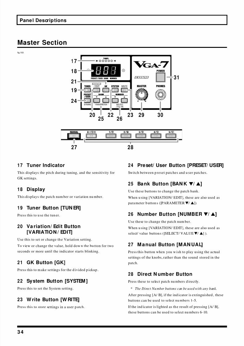
8/3/2019 VGA-7 Guitar Amplifier User's Manual
http://slidepdf.com/reader/full/vga-7-guitar-amplifier-users-manual 34/56
34
Panel Descriptions
Master Section
fig.103
17 Tuner Indicator
This displays the pitch during tuning, and the sensitivity for
GK settings.
18 Display
This displays the patch num ber or variation nu mber.
19 Tuner Button [TUN ER]
Press this to u se the tun er.
20 Va riation/ Edit Button[VARIATION / EDIT]
Use this to set or change th e Variation setting.
To view or change the value, hold dow n the bu tton for two
seconds or more until the indicator starts blinking.
21 GK Button [GK]
Press this to m ake settings for the d ivided p ickup .
22 System Button [SYSTEM ]
Press this to set the System setting.
23 W rite Button [W RITE]
Press this to store settings in a user p atch.
24 Preset/ User Button [PRESET/ USER]
Switch between p reset patches and u ser patches.
25 Bank Button [BAN K w/ v]
Use these buttons to change the patch bank.
When u sing [VARIATION/ EDIT], these are also used as
para meter b utton s ([PARAMETERw / v]).
26 Number Button [NUMBER w/ v]
Use these to change the patch num ber.
When u sing [VARIATION/ EDIT], these are also used as
select/ value button s ([SELECT/ VALUEw / v] ).
27 M anual Button [MAN UAL]
Press this button when you w ish to play using the actual
settings of the knobs, rather than the sound stored in the
patch.
28 Direct N umber Button
Press these to select patch nu mbers d irectly.
* The Direct Nu mber buttons can be used with any bank.
After pressing [A/ B], if the ind icator is extinguished , these
buttons can be used to select nu mbers 1–5.
If the ind icator is lighted as th e result of pressing [A/ B],
these buttons can be used to select nu mbers 6–10.
25 26
19
24
22 2320
21
18
17
29 30
31
27 28

8/3/2019 VGA-7 Guitar Amplifier User's Manual
http://slidepdf.com/reader/full/vga-7-guitar-amplifier-users-manual 35/56
35
Panel Descriptions
29 Master Knob [MASTER]
Adjust the speaker volume or headp hone volume of the
VGA-7.
* The setting of the master knob is not memorized.
30 Headphones Jack (PHONES)
Head phon es are plugged in here.
* When headphones are connected, sound will not be output
from the speaker of the VGA-7.
* Before connecting or disconnecting headphones, you must set
[MAS TER] to 0.
31 Pow er Sw itch [POW ER]
Turns the power on/ off.
* Before turning the power switch on/off, you must set
[MAS TER] to 0.
Rear Panel
fig.41
32 Line Out Jacks(LIN E OUT L (MON O)/ R)
These outp ut the sound of the pre-amp, including the effect
section.
External devices such as a m ixer can be connected h ere.
When using m ono outpu t, make the connection to the L
(MONO) jack.
33 EXT Input Jacks(EXT IN L (MO N O)/ R)
These are stereo external inpu t jacks.
External devices such as a gu itar synthesizer can be
connected here.
The sound that is inpu t will be outpu t from the internal
speaker and from the h eadph ones and line out jacks.
You can u se the Master knob to adjust the volume.
When using m ono input, make the connection to the L
(MONO) jack.
34 FOOT CON TROL
* If the plug is connected or disconnected while the power is on,
the effect on/off, patch, or manual/memory settings may change.
* When connecting the FS-5U/FS-5L (sold separately) to the
FOOT SW jack, set the polarity switch as shown below.
fig.91
Ex pression Peda l Jack (EXP PEDAL)
A separ ately available expression p edal (e.g., Roland EV-5 or
BOSS FV-300L) can be connected here.
The expression p edal can be u sed as a volum e ped al to adjust
the v olum e of the VGA-7. How ever if the EFFECTS sectionINSERT type is set to WAH , the ped al will fun ction as a wah
pedal.
Rear Panel
32333435
Polarity switch

8/3/2019 VGA-7 Guitar Amplifier User's Manual
http://slidepdf.com/reader/full/vga-7-guitar-amplifier-users-manual 36/56
36
Panel Descriptions
s Turning the Effects On and Off
With the FS-5L connected, you can check the ind icator
on th e FS-5L to see w hether the effect is on or off.
The indicator is lit wh en th e effect is on; the light g oes
out w hen th e effect is turned off.
* The VGA -7’s panel controls cannot be used to turn the effects
on and off while the FS-5L is connected.
EFX Jack (EFX)
Separately sold foot sw itches (e.g., BOSS FS-5U or FS-5L) can
be connected here to turn effects on/ off.
Delay Jack (DELAY)By u sing a sep arately ava ilable connection cable (Roland
PCS-31) to connect tw o foot switches, you can use th e foot
switches in the following ways.
fig.42
TIP (w hite): DELAY
The delay effect will be turned on/ off.
RIN G (red): TAP/ HOLDUse for tap-inpu t of the delay tim e. If the delay typ e is set to
HOLD, this will function as the sw itch to start/ stop
recording.
Connect a momentary-type foot switch (BOSS FS-5U: sold
separately).
* If only one foot switch is connected, it will turn delay on/off.
Chorus Jack (CHO RUS)
You can connect a separately available foot switch (BOSS FS-
5U or FS-5L) to turn choru s on/ off.
Reverb Jack (REVERB)
You can connect a separately available foot switch (BOSS FS-
5U or FS-5L) to tur n reverb on/ off.
s Sw itching M anua l/ M emory and Patches
When the Foot Switch Type (p. 39) in the System settings
is set to “3 PROGRAM,” Manual and Memory are
switched with a foot switch connected to the EFX jack,while you can switch Patches when the foot switch is
connected to the DELAY, CHORUS, or REVERB jack.
Connect a momentary-type foot switch (BOSS FS-5U: sold
separately).
fig.104
EFX Jack
Switches between Manual m ode an d the currently selected
Patch (Memory).
DELAY Jack
* Connect tw o foot switches using the optional connection cord
(Roland PCS-31).
TIP (w hite)
Each time the foot switch is pressed, the Patch bank number
rises to the next highest in the series of num bers.
RING (red)
Each time the foot switch is pressed, the Patch bank number
decreases to the next lowest in the series of nu mber s.
CHORUS Jack
The Patch num ber decreases in sequ ence each time the foot
switch is pressed.
REVERB Jack
The Patch num ber increases in sequ ence each time the foot
switch is pressed.
Connection cable:PCS-31 (sold separately)
RING (Red)TIP (White)
Tap Tempo(Hold)
DelayOn/Off
Switching banksSwitching numbers SwitchingManual/Memory
RING(Red)
TIP(White)

8/3/2019 VGA-7 Guitar Amplifier User's Manual
http://slidepdf.com/reader/full/vga-7-guitar-amplifier-users-manual 37/56
37
Panel Descriptions
35 MIDI
MIDI IN Connector
By connecting a sepa rately ava ilable MIDI foot controller
(e.g., Roland FC-200) you can u se your feet to switch p atches.
This connector is also used to receive data from an extern al
MIDI device.
M IDI O UT Connector
This connector is used to tra nsmit VGA-7 da ta to an external
MIDI device.
* Depending on the system sett ings, this connector can also be
used as a MIDI THR U connector which re-transmits t he data
received at M IDI IN without change. (p. 42)

8/3/2019 VGA-7 Guitar Amplifier User's Manual
http://slidepdf.com/reader/full/vga-7-guitar-amplifier-users-manual 38/56
38
System setting
Procedure
fig.82 1. Press [SYSTEM], getting the indicator to light.
2. Press [PARAMETERw / v] to select the pa ram eter
number.
3. Press [SELECT/ VALUEw / v] to inpu t the value.
4. Once you’ve finished making settings, press [SYSTEM]
again, extinguishing its indicator.
The setting will be saved .
A list of system p aram eters is given on th e plate located on the top right of the cabinet.
fig.81
TUN ER
Parameter Number: 1 PITCH
Specify the standard pitch.
Display Setting
35 –45 435 –445 Hz
* With the factory settings, this is set to “440 Hz.”
Parameter Number: 2 LEVEL
Specify the outpu t level of the tun ing sound .
Display Setting
0 –10 0 (MUTE: sound will not be outpu t while tuning) –
10
* With the factory settings, this is set to “0.”
N OISE SUPRESSOR
This effect reduces the noise and hu m p icked u p by guitar
pickup s. Since it sup presses the noise in synchronization
with the envelope of the guitar sound (the way in wh ich the
guitar sou nd decays over tim e), it has very little effect on th e
guitar sound, and does not harm the natural character of the
sound.
Parameter Number: 3 THRESHOLD
Adjust this parameter as app ropriate for the volum e of the
noise. If the n oise level is high, a high er setting is
app ropr iate. If the noise level is low, a lower setting is
approp riate. Adjust this value until the d ecay of the guitar
sound is as natural as possible.
This can be tu rned off by setting the va lue to 0.
Display Setting
0 –10 0 (OFF)–10
* With the factory settings, this is set to “4.”
* High sett ings for the threshold parameter may result in there
being no sound when you play with your guitar volume
turned down.
2
1,4
3

8/3/2019 VGA-7 Guitar Amplifier User's Manual
http://slidepdf.com/reader/full/vga-7-guitar-amplifier-users-manual 39/56
39
System setting
Foot Sw itch (FOOT SW )
Specify the operat ion of the foot switches conn ected to the
EFX–REVERB jacks.* You cannot change the settings for each individual jack.
Parameter Number: 4 TYPE
Display Setting
1 EFFECTS (MOMENTARY):
The effect on/ off state specified by the p atch
will be reversed . If the effect is on, it will be
switched off → on → off → on... when the
switch is pressed. If the effect is off, it will be
switched on→
off →
on→
off... wh en th eswitch is pressed.
* Connect a momentary-type foot switch
(sold separately: BOSS FS-5U).
2 EFFECTS (LATCH):
The foot switch’s current status is the one used,
regard less of the Patch’s effects status (on/ off).
* When this setting is selected, the effects cannot be
turned on and off with the buttons on the front panel.
* Connect a latch-type foot switch (sold separately:
BOSS-FS-5L). Be sure to connect the FS-5U to the
DELAY jack’s RING.
3 PROGRAM:
Manual and Memory are switched u sing a foot
switch conn ected to th e EFX jack, while you can
switch Patches wh en the foot switch is
conn ected to th e DELAY, CHORUS, or REVERB
jack.
* Connect a momentary-type foot switch
(sold separately: BOSS FS-5U).
* With the factory settings, this is set to
“1 EFFECTS (MOM ENTA RY).”
Ex pression Pedal (EXP PEDAL)
Specify how the expression p edal w ill behave wh en the
patch is changed.
Parameter Number: 5 PEDAL HOLD
Display Setting
1 ON:
When the p atch is changed , the volume w ill be
as specified by the p osition of the p edal.
2 OFF:
When the p atch is changed , the volume w ill be
as specified by th e [VOLUME] setting of the
COSM amp lifier, regardless of the p osition of the pedal.
* With the factory settings, this is set to “1 ON.”
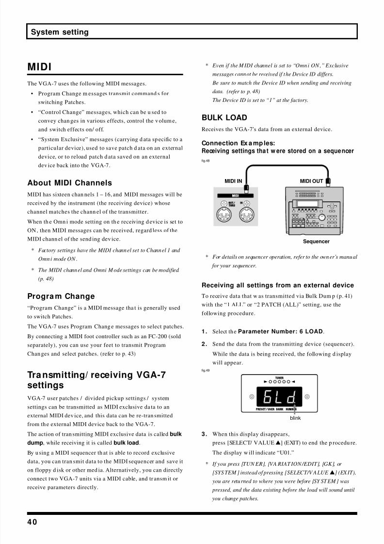
8/3/2019 VGA-7 Guitar Amplifier User's Manual
http://slidepdf.com/reader/full/vga-7-guitar-amplifier-users-manual 40/56
40
System setting
MIDI
The VGA-7 uses the following MIDI messages.
• Program Change m essages transmit command s forswitching Patches.
• “Control Change” messages, which can be u sed to
convey chan ges in various effects, control the v olum e,
and switch effects on/ off.
• “System Exclusive” messages (carrying d ata sp ecific to a
particular device), used to save patch d ata on an external
device, or to reload patch d ata saved on an external
dev ice back into the VGA-7.
About MIDI Channels
MIDI has sixteen chan nels 1 – 16, and MIDI messages will be
received by the instrument (the receiving device) whose
channel matches the chann el of the transmitter.
When th e Omn i mode setting on th e receiving d evice is set to
ON , then MIDI messages can be received, regard less of the
MIDI chann el of the send ing dev ice.
* Factory settings have the MIDI channel set to Channel 1 and
Omni mode ON .
* The MIDI channel and Omni Mode settings can be modified.
(p. 48)
Progra m Change
“Program Change” is a MIDI message tha t is generally used
to switch Patches.
The VGA-7 uses Program Chang e messages to select patches.
By connecting a MIDI foot controller such as an FC-200 (sold
separately), you can use your feet to transmit Program
Chan ges and select patches. (refer to p. 43)
Transmitting/ receiving VGA-7settings
VGA-7 user patches / divided pickup settings / system
settings can be transmitted as MIDI exclusive da ta to an
external MIDI dev ice, and this data can be re-tran smitted
from th e external MIDI device back to the VGA-7.
The action of tran smitting MIDI exclusive data is called bulk
dump, while receiving it is called bulk load.
By u sing a MIDI sequencer th at is able to record exclusive
data, you can tran smit data to the MIDI sequencer and save it
on floppy d isk or other med ia. Alternatively, you can directly
connect two VGA-7 units via a MIDI cable, and tr ansm it or
receive parameters directly.
* Even if the MIDI channel is set to “Omni ON,” Exclusive
messages cannot be received if the Device ID differs.
Be sure to match the Device ID when sending and receiving
data. (refer to p. 48)
The Device ID is set to “1” at the factory.
BULK LOAD
Receives the VGA-7’s data from an external device.
Connection Ex amples:Receiving settings tha t w ere stored on a sequencer
fig.48
* For details on sequencer operation, refer to the owner’s manual
for your sequencer.
Receiving all settings from an external deviceTo receive data that w as transmitted via Bulk Dum p (p. 41)
with the “1 ALL” or “2 PATCH (ALL)” setting, use the
following procedure.
1. Select the Parameter Number: 6 LOAD.
2. Send the data from the transmitting device (sequencer).
While the data is being received, the following d isplay
will appear.
fig.49
3. When this display disappears,
press [SELECT/ VALUEv] (EXIT) to end the p rocedu re.
The display w ill indicate “U01.”
* If you press [TUN ER], [VA RIATION/EDIT], [GK], or
[SYS TEM ] instead of pressing [SELECT/V ALUE v] (EXIT),
you are returned to where you were before [SY STEM] was
pressed, and the data existing before the load will sound until
you change patches.
MIDI OUT
Sequencer
MIDI IN
blink

8/3/2019 VGA-7 Guitar Amplifier User's Manual
http://slidepdf.com/reader/full/vga-7-guitar-amplifier-users-manual 41/56
41
System setting
Receiving only one patch
* You cannot operate this procedure in Manual mode.
To receive data that w as transmitted via Bulk Dum p (p. 41)
with the “3 PATCH (ONE)” setting, use the followingprocedure.
1 . Use [BAN Kw / v], [NUMBERw / v] ([PRESET/ USER])
to select the user p atch that you wish to receive.
2 . Select the Parameter Number: 6 LOAD.
* You can use the direct number buttons to change the number
of the patch to be received.
3 . Send the d ata (one patch) from the transmitted d evice
(sequencer).
While the data is being received, the following d isplay
will appear.
fig.49
4 . When this display disappears,
press [SELECT/ VALUEv] (EXIT) to end the p rocedu re.
The user pa tch you selected in step 1 will be displayed .
* If you press [TUN ER], [VA RIATION/EDIT], [GK], or
[SYS TEM] instead of pressing [SELECT/V ALUE v] (EXIT),
you are returned to where you were before [SY STEM] was
pressed, and the data existing before the load will sound until
you change patches.
BULK DUM P
Send s MIDI messages to an external dev ice.
* It is not possible to transmit the data being edited. Use the
Write operation to save the data before transmitting it.
Connection Ex amples:Saving da ta on a sequencer
Prepare your sequencer to receive exclusive data.
fig.52
If par ameter n um ber 8 FUN CTION is set to “2 THRU,”
the MIDI OUT connector w ill function as a MIDI THRU
connector. However, wh en d ata is being transmitted, it
will temp orarily function as a MIDI OUT connector, and
will then revert to th e MIDI THRU function wh en
transm ission is finished .
* For details on sequencer operation, refer to the owner’s manual
for your sequencer.
Transmitting data
1. Select the Para meter Number: 7 DUM P.
2 . Press [SELECT/ VALUEw / v] to select the data t hat w ill
be transmitted.
Display Setting
1 ALL:
All settings (all user patches / divided pickup
settings / system settings) will be transmitted.
2 PATCH (ALL):
Data for all user p atches will be transmitted.
3 PATCH (ONE):
Data for the currently selected user pa tch will be
transmitted. You can use the direct number
buttons to select the num ber of the patch that
will be transmitted.
* You cannot select this setting in Manual mode.
* With the factory settings, this is set to “1 ALL.”
blink
If Bulk Load cannot b e executed correctly, an error
message a pp ears, and the [SYSTEM] ind icator flashes.
Take the app ropriate action according to th e m essage
displayed.
* Press [SY STEM ] to restore the Bulk Load to previous
status.
fig.88a
Reason: A large amount of MIDI data was received
in a short time and could n ot be processed.
Action : Check that the transm itting d evice is not
transm itting excessive amou nts of MIDI data.
MIDI IN
Sequencer
MIDI OUT

8/3/2019 VGA-7 Guitar Amplifier User's Manual
http://slidepdf.com/reader/full/vga-7-guitar-amplifier-users-manual 42/56
42
System setting
3 . Press [WRITE] to send the d ata.
The following display w ill app ear wh ile the da ta is being
transmitted.
fig.53
* When A LL/PATCH (A LL) is selected, it takes approximately
40 seconds to complete transmission of the data.
4 . When the transmit data selection display reapp ears,
press [SYSTEM] to end the p rocedu re.
Sending Only the Divided Pickup Settings andSystem Settings
1 . While holding dow n [GK] and [SYSTEM], turn on th e
pow er switch.
[WRITE] ind icator will blink, the following w ill appear
in the d isplay.
fig.98
* To cancel transmission, press either [TUN ER],
[VARIATION /EDIT], [GK], or [SYST EM].
2 . Press [WRITE] to send the d ata.
The following display w ill app ear wh ile the da ta is being
transmitted.
fig.99
When transm ission is finished, the p atch or man ual
mod e that w as selected at the time th e POWER switch
wa s turn ed off will be selected.
M IDI OUT
Parameter Number: 8 FUNCTION
Here’s how to chan ge the function of the MIDI OUT
connector to MIDI THRU.
* At the factory settings, this is set to “MIDI OUT .”
Display Setting
1 OUT:
The connector w ill fun ction as MIDI OUT.
2 THRU:
The connector w ill fun ction as MIDI THRU.
MIDI messages received at MIDI IN will be re-
transmitted without change.
blink
blink

8/3/2019 VGA-7 Guitar Amplifier User's Manual
http://slidepdf.com/reader/full/vga-7-guitar-amplifier-users-manual 43/56
43
Opera ting the VGA-7 w ith the FC-200
With the optiona l FC-200 MIDI Foot Controller, you can u se ped al opera tions to control the VGA-7.
Initializing the FC-2 00 fromthe VGA-7
Provide the FC-200 with th e VGA-7’s settings by sending the
da ta from the VGA-7.
At the same time that the FC-200 is in itialized , the
VGA-7 will also be set to settings suitable for the FC-
200.
For the se ttings that wil l be changed, refer to p. 48.
1 . Use a M IDI cable to conn ect the VGA-7’s MIDI OUT and
the FC-200’s MIDI IN connectors.
fig.84
2 . While Holding d own [VARIATION/ EDIT] and turn on
the VGA-7’s POWER switch.
“FC” an d “200” app ear alternately in th e display, and
the [WRITE] indicator flashes.
* To cancel the operation, press either [TUNER],
[VARIATION /EDIT], [GK], or [SYST EM].
3 . After confirming th at th e FC-200’s pow er switch is on,
pr ess [WRITE].
During transmission, “–” appears, moving from left to
right across the display.
When transmission is finished, the unit returns to the
status in effect before the last time the p ower w as turn ed
off.
This completes initialization of the FC-200.
* Immediately after initialization, the VGA-7 w ill be in
Program Change mode (p. 44 ).
Connecting the VGA-7 andthe FC-200
fig.90
Set the VGA-7’s MIDI channel to “OMNI ON” or to the
same channel set for the FC-200 (p. 48).
* This is set at the factory to “OMN I ON.”
With an optiona l FS-5U foot switch connected to the FC-
200’s Mode jack, you can use th e setup to sw itch
between Program Change m ode, used for switching
Patches, and Control Change mod e, in w hich Control
Change m essages are sent.
* When connecting the FS-5U (sold separately) to the FOOT
SW jack, set the polarity switch as shown below.
fig.91
FC-200MIDI IN
MIDI OUT
FC-200
MIDI OUT
MIDI IN
Polarity switch

8/3/2019 VGA-7 Guitar Amplifier User's Manual
http://slidepdf.com/reader/full/vga-7-guitar-amplifier-users-manual 44/56
44
Operating the VGA-7 w ith the FC-200
Functions That Can BeControlled w ith the FC-200
In Program Change Modefig.95
Sw itching Betw een Preset Patches andUser Patches
* Distinctions between Preset and User Patches follow the
VGA -7 settings.
Sw itching Bank s
Each time the Bank (UP/ DOWN) ped al is pressed, the bank
is switched, and the Bank is ind icated on th e FC-200’sdisplay.
Press “UP” to rise through th e bank nu mbers in sequence;
press “DOWN” to descend throu gh th e sequence of Bank
numbers.
Sw itching Numbers
Press the Nu mber ped als (1–10) to select the nu mbers. The
selected nu mber indicator lights, and the p rogram nu mber is
switched.
When switching to a Patch of a different num ber within the
same Bank, reselection of the Bank is un necessary.
When in Control Change mode, you can use the UP bank
pedal to switch betw een Preset and User Patches.
Turning the Tuner On and Off
Each time the control ped al is pressed , the informa tion
controlled w ith the p edal is sent from th e FC-200 as a Control
Chan ge message (Controller Nu mber 80).
These messages can be used to tu rn the VGA-7’s tuner on
and off.
Controlling the Volume (W ah)
When the expression pedal is used, the information
controlled w ith the p eda l is sent from th e FC-200 as a Control
Change message (Controller Number 7).
These messages can be used to control the VGA-7’s volum e
level.
When EFX in the EFFECTS section is on , with the TYPE set to
“WAH,” you can u se the expression ped al as a wah p edal.
In Control Change M ode
In Control Change m ode, the various pedals are used to send
the Control Change messages shown below.
These messages can be used to control the VGA-7’s d ifferent
functions.
fig.97
Sw itching Preset and User Patches
Each time th e UP Bank p edal is pressed, the information
controlled w ith the p eda l is sent from th e FC-200 as a Control
Change message (Controller Number 75).
These messages can be used to switch between Preset and
User Patches.
Turning the Capo Function On and Off
Each time Number pedal 6 is pressed, the information
controlled w ith the p eda l is sent from th e FC-200 as a ControlChange message (Controller Number 70).
These messages can be u sed to turn the Capo function on and
off.
Switching BanksSwitching Numbers
Turning the Tuner On and Off Controlling theVolume (Wah)
Turning the Capo FunctionOn and Off (#70)
Switching Preset andUser Patches (#75)
Turning the EFX On and Off (#65)
Turning the Delay On and Off (#66)
Turning the Chorus On and Off (#67)
Turning the Reverb On and Off (#68)
Delay Time Tap Input (#69);When “HOLD” is selected as the Delay type,this is used to start and stop recording.
Switching BetweenManual and Memory (#76)
Controlling the
Volume (Wah) (#7)Turning theTuner On and Off (#80)
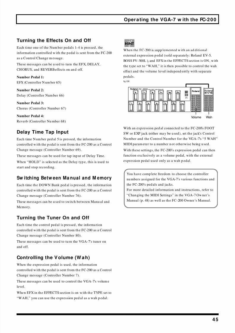
8/3/2019 VGA-7 Guitar Amplifier User's Manual
http://slidepdf.com/reader/full/vga-7-guitar-amplifier-users-manual 45/56
45
Operating the VGA-7 w ith the FC-200
Turning the Effects On and Off
Each time one of the Num ber pedals 1–4 is pressed , the
information controlled w ith the p edal is sent from the FC-200
as a Control Change m essage.
These messages can be u sed to turn the EFX, DELAY,
CHORUS, and REVERB effects on an d off.
Number Pedal 1:
EFX (Controller N um ber 65)
Number Pedal 2:
Delay (Controller Num ber 66)
Number Pedal 3:
Chorus (Controller Number 67)
Number Pedal 4:Reverb (Controller Nu mber 68)
Delay Time Tap Input
Each time N um ber ped al 5 is pressed, the informa tion
controlled w ith the p edal is sent from th e FC-200 as a Control
Change message (Controller Number 69).
These messages can be used for tap inp ut of Delay Time.
When “HOLD” is selected as the Delay typ e, this is used to
start and stop recording.
Sw itching Betw een Ma nual and M emory
Each time th e DOWN Bank ped al is pressed , the informa tion
controlled w ith the p edal is sent from th e FC-200 as a Control
Change message (Controller Number 76).
These messages can be u sed to switch between Manu al and
Memory.
Turning the Tuner On and Off
Each time the control ped al is pressed , the informa tion
controlled w ith the p edal is sent from th e FC-200 as a Control
Change message (Controller Number 80).
These messages can be used to tu rn the VGA-7’s tuner on
and off.
Controlling the V olume (W ah)
When the expression pedal is used, the information
controlled w ith the p edal is sent from th e FC-200 as a Control
Change message (Controller Number 7).
These messages can be used to control the VGA-7’s volum e
level.
When EFX in th e EFFECTS section is on with th e TYPE set to
“WAH,” you can use the expression ped al as a wah p edal.
When the FC-200 is supp lemented w ith an ad ditional
external expression p edal (sold sep arately: Roland EV-5,
BOSS FV-300L ), and EFX in the EFFECTS section is ON , with
the type set to “WAH,” it is then possible to control the wah
effect and the volume level independ ently with separate
pedals.
fig.108
With an exp ression ped al connected to th e FC-200’s FOOT
SW or EXP jack (either ma y be u sed), set the jack ’s Control
Nu mber and the Control Nu mber for the VGA-7’s “5 WAH”
MIDI param eter to a number n ot otherwise being u sed.
With th ese settings, the FC-200’s expression pedal can then
function exclusively as a volume pedal, with the external
expression pedal used only as a wah p edal.
Volume Wah
You h ave comp lete freedom to choose the controllernu mbers assigned for the VGA-7’s various functions and
the FC-200’s ped als and jacks.
For more detailed information and instructions, refer to
“Chan ging the MIDI Settings” in the VGA-7 Ow ner ’s
Manual (p. 48) as well as th e FC-200 Owner ’s Manual.

8/3/2019 VGA-7 Guitar Amplifier User's Manual
http://slidepdf.com/reader/full/vga-7-guitar-amplifier-users-manual 46/56
46
Appendices
If You Think There Might Be a Problem (Troubleshooting)
This section explains some things that m ight go wrong wh en using the VGA-7, and what needs to be d one to correct the
problem.If you think there may be something wrong with your VGA-7, please check through the following first.If these suggestions d on’t fix the problem, then go ah ead an d contact the store you bou ght it from, or your nearest Roland Service
Station.
s Trouble w ith the Sound
The sound isn’t right.
q Is the divided pickup setting correctly?
→ Check the divided pickup setting. (p. 15–19)
q Is the selector switch on the GK pickup set to“GUITAR”?
→ Set the select switch to a setting other th an “GUITAR.”
There is no sound w hen the guitar isplayed.
q Is the divided pickup connecting correctly?
→ Check the conn ections are correct. (p. 12)
q Is the SYNTH VOL on the GK-2A set to “0”?
→Raise the volume to an app ropriate level.
q Are [MASTER], [GAIN], or [VOLUME] on the VGA-
7 set to “0”?
→ Raise the volume to an app ropriate level.
q Are [BASS], [MIDDLE], and [TREBLE] all set to
“0”?
→ Depending on the amp type (p. 28), there m ay be no
sound if you set th e [BASS], [MIDDLE], and [TREBLE]
equa lizer settings all to 0.
q Are you using the expression pedal?→ If the expression pedal is returned (toward yourself),
there may be no soun d. Advan ce the pedal (away from
yourself).
The pitch isn’t right.
q Is the guitar in tune?
→ Tune the gu itar. (p. 21)
q Is the VGA-7 out of tune with other instruments?
→ Adjust the Standard pitch setting. (p. 20)
q Have you set TUNING or CAPO for the COSM GUITAR?
→ Set the TUNING of the COSM GUITAR to NORMAL,
and turn CAPO off.
The volume fluctuates from one stringto another.
q Are the Sensitivity settings for all strings correct?→ Ad just th e settings if necessary. (p. 17)
Onboa rd effects are not applied.
q Is the effect turned “OFF”?
→ If an effect is turn ed “OFF,” that effect will not be
app lied. Turn the effect “ON .”
q Are the effect levels high enough?
→ An effect is not app lied and on ly the original soun d is
heard wh en th e effect level is at the lowest setting. Set
the effect level to an app ropr iate value.
Depending on the guitar being used,hum may be audible.
q Is the output jack on your guitar connected to the
NORMAL GUITAR input jack on the GK-2A?
→ You shou ld be sure to m ake this connection even if the
guitar sound is not to be outpu t. For more d etails, see the
Owner’s Manu al for the GK-2A.
s Other Problems
“ ” is display ed w hen the pow eris sw itched on.
→ The internal battery for saving Patch and system
parameters is almost out of power. Replace the battery
soon to prevent parameters from being lost. Contact
your n earest Roland Service Station or the store w here
you bought the VGA-7.

8/3/2019 VGA-7 Guitar Amplifier User's Manual
http://slidepdf.com/reader/full/vga-7-guitar-amplifier-users-manual 47/56
47
Appendices
Patches aren’t sw itched w hen aProgram Change is received from anex ternal device.
q Are Program Change messages being transmitted on
a channel other than the selected MIDI channel?
→ Send th e Program Change m essages on the same channel
as the one set with MIDI Chann el (p. 48).
Data can’t be sent or received w ithBulk Dump.
q Have you made settings to allow bulk dump
transmission?
→ In the System settings, select para meter n um ber 7:
DUMP, specify the data to be transmitted, and then
execute bulk du mp .
q Is the MIDI sequencer you are using able to record
exclusive data?
→ Use a MIDI sequencer th at can record SysEx messages.
We recomm end that you use the Roland MC-80.
The volume level of the instrumentconnected to EXT IN is too low .
q Could you be using a connection cable thatcontains a resistor?
→ Use a connection cable that d oes not contain a r esistor.
Restoring the Factory Settings
You can restore the VGA-7 to its factory setting s. This
operation is called “Factory Reset.”
Once you carry ou t a Factory Reset, all of the existing
data that you’ve created w ill be lost.
If there is any imp ortant data that you wish to keep, use
Bulk Dum p (p. 41) to save the d ata on an extern al MIDI
device (such as a sequencer) beforehand.
1. While holding d own [WRITE], turn on the POWER
switch.
The [WRITE] indicator flashes, and the followingmessages alternate repeatedly in the d isplay.
fig.89a
s Restoring All Settings to the Va lues Set a tthe Factory
2. Press [WRITE].
Factory Reset is executed .
During the operation, “–” appears, moving from left to
right across the display.
When Factory Reset is finished, “U01” app ears in the
display.
1.
s Restoring Only the User Patches to theFactory Settings
2. Press [PRESET/ USER].
The following messages alternate repeatedly in the
display.fig.89b
3. Press [WRITE].
Factory Reset is executed .
During the operation, “–” appears, moving from left to
right across the display.
When Factory Reset is finished, “U01” app ears in the
display.

8/3/2019 VGA-7 Guitar Amplifier User's Manual
http://slidepdf.com/reader/full/vga-7-guitar-amplifier-users-manual 48/56
48
Appendices
Changing the MIDI Settings
When u sing MIDI to control the VGA-7, you can chan ge the settings for the MIDI par ameters as need ed.
1 . While holding dow n [SYSTEM], turn on the POWER switch.
2 . Use [PARAMETERw / v] to select MIDI param eters.
3 . Press [SELECT/ VALUEw / v] to set the value.
4 . Press eith er [TUNER], [VARIATION/ EDIT], [GK], or [SYSTEM] to stop th e operation .
* If two or all of “6 TUN ER,” “d PRESET/USER,” and “E MA NUA L/MEMORY ” are set to the same controller number, control will be
given priority in the order of 1: 6 TUNER, 2: E MANUA L/MEM ORY , and 3: d PRESET/USER, and control of the remaining
parameter(s) will be disabled.
With the foot volume an d th e WAH controller nu mber both set to the same num ber, you can use a single expression p edal to
control both the volum e and the wah effect, the pedal acting as a wah pedal w hen the WAH effect is on, and as a volume
ped al when the w ah effect is off.
Parameter No. ValueFactory
Setting
Setting
for FC-200
1 MIDI CH (Sett ing for MIDI channel) 1–16 1 1
2 OMNI (Setting for Omni mode) On, OFF On On
3 D EVICE ID (Settin g fo r Dev ice ID ) 1–32 1 1
4 Foot Volume (Controller No.) 1–31, 64–95 7 7
5 WAH (Controller No.) 1–31, 64–95 7 7
6 TUNER (Controller No.) 1–31, 64–95 80 80
7 EFX (Controller No.) 1–31, 64–95 65 65
8 DELAY (Controller No.) 1–31, 64–95 66 66
9 CHORUS (Controller No.) 1–31, 64–95 67 67
A REVERB (Controller No.) 1–31, 64–95 68 68
b TAP (Controller No.) 1–31, 64–95 69 69
c CAPO (Controller No.) 1–31, 64–95 70 70
d USER/ PRESET (Controller No.) 1–31, 64–95 75 75
E MANUAL/ MEMORY (Controller N o.) 1–31, 64–95 64 76
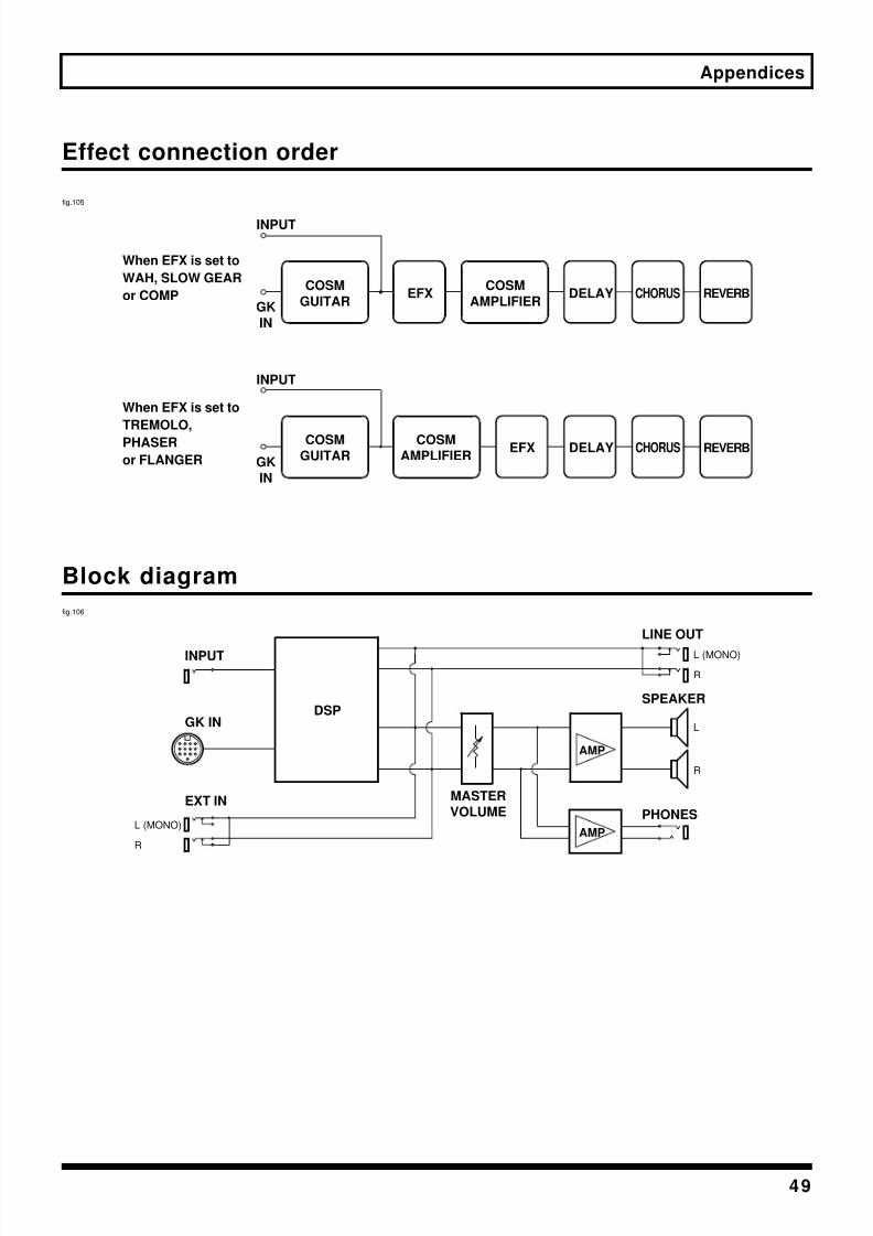
8/3/2019 VGA-7 Guitar Amplifier User's Manual
http://slidepdf.com/reader/full/vga-7-guitar-amplifier-users-manual 49/56
49
Appendices
Effect connection order
fig.105
Block diagram
fig.106
COSM
GUITAREFX
COSM
AMPLIFIERDELAY CHORUS REVERB
COSM
GUITAREFX
COSM
AMPLIFIERDELAY CHORUS REVERB
When EFX is set to
WAH, SLOW GEAR
or COMP
When EFX is set to
TREMOLO,
PHASER
or FLANGER
INPUT
GK
IN
INPUT
GK
IN
DSP
MASTER
VOLUME
AMP
AMP
LINE OUT
SPEAKER
PHONESEXT IN
GK IN
INPUT
L (MONO)
R
L (MONO)
R
L
R

8/3/2019 VGA-7 Guitar Amplifier User's Manual
http://slidepdf.com/reader/full/vga-7-guitar-amplifier-users-manual 50/56
50
Appendices
MIDI Implementation Chart
Function...
Basic
Channel
Mode
Note
Number :
Velocity
After
Touch
Pitch Bend
Control
Change
Prog
Change
System Exclusive
System
Common
System
Real Time
Aux
Message
Notes
Transmitted Recognized Remarks
Default
Changed
Default
Messages
Altered
True Voice
Note ON
Note OFF
Key's
Ch's
0, 32
1 – 31
64 – 95
: True #
: Song Pos
: Song Sel: Tun e
: Clock
: Comman d
: All sound off : Local ON/ OFF: All Notes OFF: Active Sense: Reset
1 – 16
1 – 16
X
X
XX
X
**************
X
X
X
X
X
X
O
O
O
*1
*2
*2
X
X
O
X
XX
X
X
XXXXX
1 – 16
1 – 16
OMNI ON/OFF
X
XX
X
X
X
X
O
0 – 79
O
X
XX
X
X
XXXXX
Bank Select
* 1 This ignores the LSB.
* 2 This recognize the message set for “Parameters realtime control.”
* 3 Bulk data can be transmitted only when the MIDI Bulk Dump screen is displayed.
* 4 Bulk data can be received only when the MIDI Bulk Load screen is displayed.
Model VGA-7
Date : Aug. 1, 2000
Version : 1.00MIDI Implementation Chart
**************
Mode 1 : OMNI ON, POLY
Mode 3 : OMNI OFF, POLY
Mode 2 : OMNI ON, MONO
Mode 4 : OMNI OFF, MONO
O : Yes
X : No
Program Number
Memorized
V-GUITAR AMPLIFIER
Memorized
*3 *4
A separate pu blication titled “MIDI Implementation” is also available. It p rovides comp lete details concerning th e way MIDI has been
implemen ted on this un it. If you shou ld require this pu blication (such as when you intend to carry out byte-level program ming), please contact
the nearest Roland Service Center or auth orized Roland d istributor.
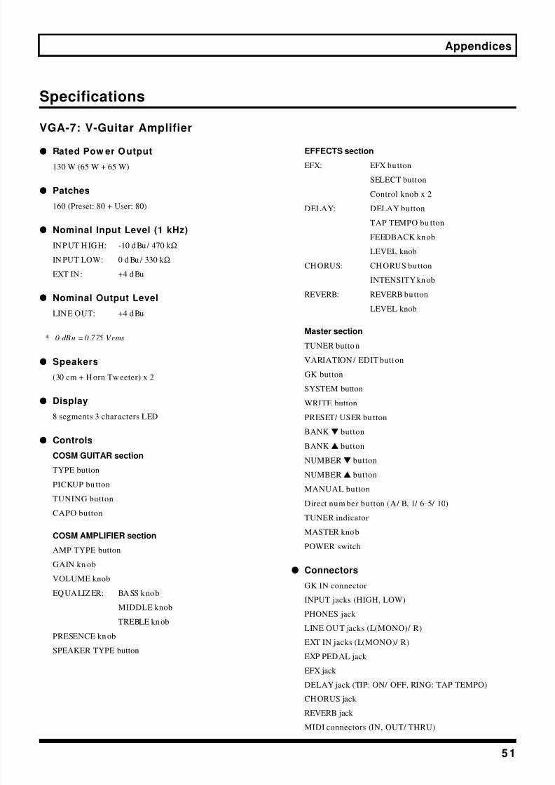
8/3/2019 VGA-7 Guitar Amplifier User's Manual
http://slidepdf.com/reader/full/vga-7-guitar-amplifier-users-manual 51/56
51
Appendices
Specifications
VGA-7: V-Guitar Amplifier
q Rated Pow er O utput
130 W (65 W + 65 W)
q Patches
160 (Preset: 80 + User: 80)
q Nominal Input Level (1 kHz)
INPUT HIGH: -10 dBu/ 470 k Ω
IN PUT LOW: 0 d Bu / 330 k Ω
EXT IN: +4 dBu
q Nominal Output Level
LINE OUT: +4 dBu
* 0 dBu = 0.775 Vrms
q Speakers
(30 cm + H orn Tw eeter) x 2
q Display
8 segments 3 char acters LED
q Controls
COSM GUITAR section
TYPE button
PICKUP bu tton
TUNING button
CAPO button
COSM AMPLIFIER section
AMP TYPE button
GAIN kn ob
VOLUME knob
EQUALIZER: BASS knob
MIDDLE knob
TREBLE kn ob
PRESENCE kn ob
SPEAKER TYPE button
EFFECTS section
EFX: EFX button
SELECT button
Control knob x 2
DELAY: DELAY button
TAP TEMPO bu tton
FEEDBACK knob
LEVEL knob
CHORUS: CHORUS button
INTENSITY knob
REVERB: REVERB button
LEVEL knob
Master section
TUNER butto n
VARIATION / EDIT butt on
GK button
SYSTEM button
WRITE button
PRESET/ USER bu tton
BANKw button
BANKv button
NUMBERw button
NUMBERv button
MANUAL button
Direct num ber button (A/ B, 1/ 6–5/ 10)
TUNER indicator
MASTER knob
POWER switch
q Connectors
GK IN connector
INPUT jacks (HIGH, LOW)
PHONES jack
LINE OU T jacks (L(MONO)/ R)
EXT IN jacks (L(MONO)/ R)
EXP PEDAL jack
EFX jack
DELAY jack (TIP: ON/ OFF, RING: TAP TEMPO)CHORUS jack
REVERB jack
MIDI connectors (IN, OUT/ THRU)

8/3/2019 VGA-7 Guitar Amplifier User's Manual
http://slidepdf.com/reader/full/vga-7-guitar-amplifier-users-manual 52/56
52
Appendices
q Pow er Supply
AC 117 V, 230 V or 240 V
qPow er Consumption160 W (117 V, 230 V, 240 V)
q Dimensions
770 (W) x 300 (D) x 640 (H) mm
30 - 3/ 8 (W) x 11-13/ 16 (D) x 25 - 1/ 4 (H) inches
(Includ e casters)
q Weight
37.6 kg / 82 lbs 15 oz
q Accessories
GK Connecting Cable: C-13A (5 m)
Casters (x4)
Owner’s Manual
Preset Patch List
q Options
Divided Pickup: GK-2A
Unit Selector: U S-20
Expression Pedal: EV-5, FV-300L (BOSS)
Foot Switch: FS-5U (BOSS), FS-5L (BOSS)
MIDI Foot Con troller: FC-200
In the interest of prod uct imp rovem ent, the specifications
and/ or app earance of this unit are subject to change
without prior notice.

8/3/2019 VGA-7 Guitar Amplifier User's Manual
http://slidepdf.com/reader/full/vga-7-guitar-amplifier-users-manual 53/56
53
Index
Numerics
12 STRING ...................................................................... 26
1-12” OPEN .................................................................... 30
2-12” OPEN .................................................................... 304-10” OPEN .................................................................... 30
4-12” CLOSED ............................................................... 30
A
A/ B .................................................................................. 22
ACOUSTIC ..................................................................... 26
ATTACK ......................................................................... 31
B
BANK ........................................................................ 22, 34BASS ................................................................................ 29
BULK DUMP ................................................................. 41
BULK LOAD .................................................................. 40
C
CAPO .............................................................................. 27
CH ORUS .................................................................. 33, 36
CLEAN ........................................................................... 28
COMP ............................................................................. 31
COSM ................................................................................ 7
COSM AMPLIFIER ....................................................... 28
COSM GUITAR ............................................................. 25
CRUNCH ........................................................................ 28
D
DELAY ...................................................................... 32, 36
DIRECTION ................................................................... 15
E
EFFECTS ......................................................................... 30
EFX ............................................................................ 30, 36
EQUALIZER .................................................................. 29
EXP PEDAL .................................................................... 35
EXT IN ............................................................................ 35
F
FEEDBACK .................................................................... 32
FLANGER ...................................................................... 32
FOOT CONTROL .......................................................... 35
FOOT SW ........................................................................ 39
FULL RANGE ................................................................ 29
FUNCTION .................................................................... 42
G
GAIN ............................................................................... 29
GK .............................................................................. 14, 34
GK IN .............................................................................. 25GK TYPE ......................................................................... 15
H
HOLLOW ....................................................................... 25
I
INPUT ............................................................................. 28
INTENSITY .............................................................. 31–33
L
LEAD ............................................................................... 28
LEVEL ..................................................... 19–20, 32–33, 38
LINE OUT ....................................................................... 35
LP ..................................................................................... 25
M
MANUAL ................................................................. 24, 34
MASTER ......................................................................... 35
MIDDLE .......................................................................... 29
MIDI .......................................................................... 40, 50
MIDI IN ........................................................................... 37
MIDI OUT ................................................................ 37, 42
N
NASHVILLE .................................................................. 27
NOISE SUPRESSOR ...................................................... 38
NORMAL ....................................................................... 26
NUMBER .................................................................. 22, 34
O
OPEN TYPE ................................................................... 26
ORIGINAL ..................................................................... 30
P
PEDAL ............................................................................ 31
PEDAL HOLD ............................................................... 39
PHASE ............................................................................ 18
PHASER .......................................................................... 32
PHONES ......................................................................... 35
PICKUP ........................................................................... 26
PICKUP-BRIDGE .......................................................... 16PITCH ....................................................................... 20, 38
POWER ........................................................................... 35
8/3/2019 VGA-7 Guitar Amplifier User's Manual
http://slidepdf.com/reader/full/vga-7-guitar-amplifier-users-manual 54/56
54
Index
PRESENCE ..................................................................... 29
PRESET/ USER ........................................................ 22, 34
RRATE ......................................................................... 31–32
REVERB .................................................................... 33, 36
RISE TIME ...................................................................... 31
S
S1/ S2 ............................................................................... 19
SCALE ............................................................................. 16
SENS .......................................................................... 17, 31
SLOW GEAR .................................................................. 31
SPECIAL ................................................................... 26, 29
ST ..................................................................................... 25
STRING ..................................................................... 17, 27
SUSTAIN ........................................................................ 31
SYSTEM .............................................................. 20, 34, 38
T
TAP TEMPO ............................................................ 32–33
TEL .................................................................................. 25
THRESHOLD ................................................................. 38
TREBLE ........................................................................... 29
TREMOLO ...................................................................... 31
TUNER ................................................................ 21, 34, 38
TUNING ................................................................... 26–27
TYPE .............................................................. 25, 28–29, 39
U
USER ............................................................................... 27
V
VARIATION ............................................................ 11, 23
VARIATION / EDIT .......................................... 23, 27, 34
VOLUME ........................................................................ 29
W
WAH ............................................................................... 31
WRITE ....................................................................... 24, 34

8/3/2019 VGA-7 Guitar Amplifier User's Manual
http://slidepdf.com/reader/full/vga-7-guitar-amplifier-users-manual 55/56
For the USA
FEDERAL COMMUNICATIONS COMMISSIONRADIO FREQUENCY INTERFERENCE STATEMENT
This equipment has been tested and found to comply with the limits for a Class B digital device, pursuant to Part 15 of theFCC Rules. These limits are designed to provide reasonable protection against harmful interference in a residentialinstallation. This equipment generates, uses, and can radiate radio frequency energy and, if not installed and used inaccordance with the instructions, may cause harmful interference to radio communications. However, there is no guarantee
that interference will not occur in a particular installation. If this equipment does cause harmful interference to radio ortelevision reception, which can be determined by turning the equipment off and on, the user is encouraged to try to correct theinterference by one or more of the following measures:
– Reorient or relocate the receiving antenna. – Increase the separation between the equipment and receiver. – Connect the equipment into an outlet on a circuit different from that to which the receiver is connected. – Consult the dealer or an experienced radio/TV technician for help.
Unauthorized changes or modification to this system can void the users authority to operate this equipment.This equipment requires shielded interface cables in order to meet FCC class B Limit.
This product complies with the requirements of European Directives EMC 89/336/EEC and LVD 73/23/EEC.
For EU Countries
For EU Countries
Apparatus containing
Lithium batteries
ADVARSEL!Lithiumbatteri - Eksplosionsfare vedfejlagtig håndtering.Udskiftning må kun ske med batteri afsamme fabrikat og type.Levér det brugte batteri tilbage til
leverandøren.
VARNINGExplosionsfara vid felaktigt batteribyte.Använd samma batterityp eller enekvivalent typ som rekommenderas avapparattillverkaren.Kassera använt batteri enligt
fabrikantens instruktion.
CAUTIONDanger of explosion if battery is
incorrectly replaced.Replace only with the same orequivalent type recommended by themanufacturer.
Discard used batteries according to themanufacturer’s instructions.
ADVARSELEksplosjonsfare ved feilaktig skifte avbatteri.Benytt samme batteritype eller en
tilsvarende type anbefalt avapparatfabrikanten.Brukte batterier kasseres i henhold tilfabrikantens instruks joner.
VAROITUSParisto voi rä jähtää, jos se onvirheellisesti asennettu.Vaihda paristo ainoastaan
laitevalmistajan suosittelemaantyyppiin. Hävitä käytetty paristovalmistajan ohjeiden mukaisesti.
For Canada
This Class B digital apparatus meets all requirements of the Canadian Interference-Causing Equipment Regulations.
Cet appareil numérique de la classe B respecte toutes les exigences du Règlement sur le matériel brouilleur du Canada.
NOTICE
AVIS

8/3/2019 VGA-7 Guitar Amplifier User's Manual
http://slidepdf.com/reader/full/vga-7-guitar-amplifier-users-manual 56/56
InformationWhen you need rep air service, call your nearest Roland Service Center or authorized Roland d istributor in your country asshown below.
ARGEN TIN AInstrumentos Musicales S.A.Florida 656 2nd Floor
Office Number 206A
Buenos Aires
ARGENTINA, CP1005
TEL: (54-11) 4- 393-6057
BRAZILRoland Brasil Ltda.R. Coronel Octaviano d a Silveira
203 05522-010
Sao Paulo BRAZIL
TEL: (011) 3743 9377CANADARoland Canada Music Ltd.(Head Office)5480 Parkwood Way RichmondB. C., V6V 2M4 CANADA
TEL: (0604) 270 6626
Roland Canada Music Ltd.
(Toronto Office)Unit 2, 109 Woodbine Downs
Blvd, Etobicoke, ON
M9W 6Y1 CANADA
TEL: (0416) 213 9707
MEXICOCasa Veerkamp, s.a. de c.v.Av. Toluca No. 323, Col. Olivar
de los Pad res 01780 Mexico D.F.MEXICO
TEL: (525) 668 04 80
PANAMASUPRO MUND IAL, S.A.Boulevard An drews, Albrook,
Panama City,
REP. DE PANAMA
TEL: (507) 315-0101
U. S. A.Roland Corporation U.S.5100 S. Eastern Aven ue
Los Angeles, CA 90040-2938,
U. S. A.
TEL: (323) 890 3700
VENEZU ELAMusicland Digi tal C.A.Av. Francisco de Miranda,
Centro Parque de Cristal, Nivel
C2 Local 20 Caracas
VENEZUELA
TEL: (02) 285 9218
AUSTRALIA Roland Corporation
Australia Pty., Ltd.38 Campbell Avenue
Dee Why West. N SW 2099AUSTRALIA
TEL: (02) 9982 8266
N EW ZEALAN DRoland Corporation (NZ) Ltd.97 Mt. Eden Road, Mt. Eden,Auckland 3, NEW ZEALAND
TEL: (09) 3098 715
HONG KONGTom Lee Music Co., Ltd.
Service Division22-32 Pun Shan Street, Tsuen
Wan, New Territories,
HONG KONG
TEL: 2415 0911
CHINABeijing Xinghai Musical
Instruments Co., Ltd.6 Huangmu chang Chao Yang
District, Beijing, CH INA
TEL: (010) 6774 7491
INDIARivera Dig itec (India) Pvt. Ltd.409, Nirman Kendra Mahalaxmi
Flats Compoun d Off. Dr. EdwinMoses Road, Mumb ai-400011,
INDIA
TEL: (022) 498 3079
INDONESIAPT Citra IntiRamaJ1. Cideng Timur No. 15J-150Jakarta Pusat
INDONESIA
TEL: (021) 6324170
MALAYSIA
Bentley Music SDN BHD140 & 142, Jalan Bukit Bintang55100 Kuala Lump ur, MALAYSIA
TEL: (03) 2443333
PHILIPPIN ESG.A. Yupangco & Co. Inc.339 Gil J. Puyat Avenu e
Makati, Metro M anila 1200,
PHILIPPINES
TEL: (02) 899 9801
SINGAPORESwee Lee Company150 Sims Dr ive,
SINGAPORE 387381
TEL: 748-1669
TAIWANROLAND TAIWAN
ENTERPRISE CO., LTD.Room 5, 9fl. No. 112 Chung Shan
N.Road Sec.2, Taipei, TAIWAN,
R.O.C.
TEL: (02) 2561 3339
THAILAN D
Theera Musi c Co. , Ltd.330 Verng NakornKasem, Soi 2,
Bangkok 10100, THAILAND
TEL: (02) 2248821
BAHRAINMoon StoresBab Al Bahrain Road,
P.O. Box 20077
State of BAHRAIN
TEL: 211 005
VIETN AMSaigon Music138 Tran Qu ang Khai St.,
District 1
Ho Chi Minh City
VIETNAM
TEL: (08) 844-4068
ISRAEL
JORDANAMMAN Trading AgencyPrince Mohammed St. P.O. Box
825 Amman 11118 JORDAN
TEL: (06) 4641200
KUWAITEasa Husain Al-YousifiAbdullah Salem Street,
Safat KUWAITTEL: 5719499
LEBAN ONA. Chahine & FilsP.O. Box 16-5857 Gergi Zeid an St.
Chahine Building, Achrafieh
Beirut, LEBANON
TEL: (01) 335799
QATARBadie Studio & StoresP.O. Box 62,
DOHA QATAR
TEL: 423554
SAUDI ARABIAaDawliah UniversalElectronics APLP.O. Box 2154 ALKHOBAR 31952,
SAUDI ARABIA
TEL: (03) 898 2081
SYRIATechnical Light & Sound
CenterKhaled Ibn Al Walid St.
P.O. Box 13520
Damascus - SYRIA
TEL: (011) 2235 384
TURKEYBarkat muzik aletleri ithalat
ve ihracat Ltd StiSiraselviler cad.Guney is han i 84-
86/ 6, Taksim. Istanbul. TURKEY
TEL: (0212) 2499324
U.A.E.Zak Electronics & Musical
Instruments Co. L.L.C.Zabeel Road, Al Sherooq Bldg.,
No. 14, Grand Floor DUBAIU.A.E.
TEL: (04) 3360715
EGYPTAl Fanny Trading OfficeP.O. Box 2904,
El Horrieh Heliopolos, Cairo,
EGYPT
TEL: (02) 4185531
REUN IONMaison FO - YAM Marcel25 Rue Jules Merma n, ZLChaud ron - BP79 97491
Ste Clotilde REUNION
TEL: 28 29 16
SOUTH AFRICAThat Other Music Shop
(PTY) Ltd.11 Melle Street (Cnr M elle and
Juta Street)
Braamfontein, 2001,
Republic of SOUTH A FRICA
TEL: (011) 403 4105
Paul Bothner (PTY) Ltd.17 Werdmuller Centre Claremont
7700
Republic of SOUTH A FRICA
P.O. Box 23032
Claremont, Cape TownSOUTH AFRICA, 7735
TEL: (021) 64 4030
CYPRUSRadex Sound Equipment Ltd.17 Diagorou St., P.O. Box 2046,
Nicosia CYPRUS
TEL: (02) 453 426
DENMARKRoland Scandinavia A/SNordhavnsvej 7, Postbox 880,
DK-2100 Copenh agenDENMARK
TEL: (039)16 6200
FRAN CERoland France SA4, Rue Paul Henri SPAAK,
Parc de l'Esplana de, F 77 462 St.Thibault, Lagny Cedex FRANCE
TEL: 01 600 73 500
FINLANDRoland Scandinavia As,
Filial FinlandLauttasaarentie 54 B
Fin-00201 Helsinki, FINLAN D
TEL: (9) 682 4020
GERMANY Roland ElektronischeMusikinstrumente HmbH.Oststrasse 96, 22844 Norderstedt,
GERMANYTEL: (040) 52 60090
GREECESTOLLAS S.A.Music Sound Light155, New National Road
26422 Patras, GREECE
TEL: 061-435400
HUNGARYIntermusica Ltd.Warehouse Area ‘DEPO’ Pf.83
H-2046 Torokbalint, HUNGARY
TEL: (23) 511011
IRELAN D
ITALYRoland Italy S. p. A.Viale delle Industrie 8,
20020 Ares e, Milan o, ITALY
TEL: (02) 937-78300
NORWAYRoland Scandinavia Avd.
Kontor NorgeLilleakerveien 2 Post boks 95
Lilleaker N-0216 OsloNORWAY
TEL: 273 0074
POLAN DP. P. H. BrzostowiczUL. Gibraltarska 4.
PL-03664 Warszawa POLAND
TEL: (022) 679 44 19
PORTUGALTecnologias Musica e Audio,
Roland Portugal, S.A.RUA DE SANTA CARARINA
131/ 133, 4000-450 PORTO
PORTUGAL
TEL: (022) 208 4456
RUSSIASlami Music CompanySadojava-Triumfalnaja st., 16
103006 Moscow, RUSSIA
TEL: 095 209 2193
SPAINRoland Electronics
de España, S. A.Calle Bolivia 239, 08020
Barcelona, SPAIN
TEL: (93) 308 1000
SWI TZERLAN D
Roland (Switzerland) AGMusitronic AGGerberstrasse 5, CH-4410 Liestal,SWITZERLAND
TEL: (061) 921 1615
SWEDENRoland Scandinavia A/S
SWEDISH SALES OFFICEDanvik Cent er 28, 2 tr.
S-131 30 Nacka SWEDEN
TEL: (08) 702 0020
UKRAINETIC-TACMira Str. 19/ 108
P.O. Box 180
295400 Munkachevo, UKRAINE
TEL: (03131) 414-40
UNITED KINGDOMRoland (U.K.) Ltd.Atlantic Close, Swansea
Enterprise Park, SWANSEA
SA7 9FJ,
UNITED KINGDOM
TEL: (01792) 700139
KOREACosmos Corporation1461-9, Seocho-Dong,
Seocho Ku, Seoul, KOREA
TEL: (02) 3486-8855
AUSTRIARoland Austria GES.M.B.H.Siemensstrasse 4, P.O. Box 74,
A-6063 RUM, AUSTRIA
TEL: (0512) 26 44 260
BELGIUM / HOLLAND/LUX EM BOURGRoland Benelux N. V.Hou tstraat 3, B-2260, Oevel
(Westerlo) BELGIUM
TEL: (014) 575811
AFRICA
CHILEComercial Fancy S.A.Avenida Rancagua #0330
Providencia Santiago, CHILE
TEL: 56-2-373-9100
URUGUAYTodo Musica S.A.Cuareim 1844, Montevideo,
URUGUAY
TEL: 5982-924-2335
EUROPE
AUSTRALIA/
N EW ZEALAN D
ASIA
CEN TRAL/ LATIN
AM ERICA
N ORTH AM ERICA
M IDDLE EAST
AFRICA
EL SALVADOROMNI MUSIC
75 Avenida Notre YY Alameda,Juan Pablo 2, N o. 4010
San Salvador, EL SALVADOR
TEL: (503) 262-0788
ROMANIAFBS LINESPlata Libertatii 1.
RO-4200 Cheorgh eni
TEL: (066) 164-609
PARAGUAYDistribuidora De
Instrumentos MusicalesJ.E. Olear y ESQ. ManduviraEdeficio, El Dorad o Planta Baja
Asuncion PARAGUAY
TEL: 595-21-492147
PERUVIDEO Broadcast S.A.Portinari 199 (ESQ. H ALS),
San Borja, Lima 41,
REP. OF PERU
TEL: 51-14-758226
La Casa Wagner de
Guadalajara s.a. de c.v.Av. Coron a No. 202 S.J.
Guad alajara, Jalisco MexicoC P 44100 MEXICO
COSTA RICAJUAN Bansbach
Instrumentos MusicalesAve.1. Calle 11, Apartad o 10237,
San Jose, COSTA RICA
TEL: (506)258-0211