vespa lxv 50 (en)
DESCRIPTION
This Service Manual describes the technical features and servicing procedures for the Vespa LXV 50TRANSCRIPT
SERVICE STATION MANUAL633860 IT- 633861 EN - 633862 FR - 633863 DE -633864 ES - 633865 PT - 633866 NL - 633867 EL
Vespa LXV 50

SERVICE STATIONMANUAL
Vespa LXV 50
The descriptions and illustrations given in this publication are not binding. While the basic specificationsas described and illustrated in this manual remain unchanged, PIAGGIO-GILERA reserves the right, at
any time and without being required to update this publication beforehand, to make any changes tocomponents, parts or accessories, which it considers necessary to improve the product or which are
required for manufacturing or construction reasons.Not all versions/models shown in this publication are available in all countries. The availability of single
versions should be checked at the official Piaggio sales network."© Copyright 2007 - PIAGGIO & C. S.p.A. Pontedera. All rights reserved. Reproduction of this publication
in whole or in part is prohibited."PIAGGIO & C. S.p.A. - After-Sales
V.le Rinaldo Piaggio, 23 - 56025 PONTEDERA (Pi)

SERVICE STATION MANUALVespa LXV 50
This workshop manual has been drawn up by Piaggio & C. Spa to be used by the workshops of Piaggio-Gilera dealers. This manual is addressed to Piaggio service mechanics who are supposed to have abasic knowledge of mechanics principles and of vehicle fixing techniques and procedures. Any importantchanges made to the vehicles or to specific fixing operations will be promptly reported by updates to thismanual. Nevertheless, no fixing work can be satisfactory if the necessary equipment and tools areunavailable. It is therefore advisable to read the sections of this manual relating to specific tools, alongwith the specific tool catalogue.
N.B. Provides key information to make the procedure easier to understand and carry out.
CAUTION Refers to specific procedures to carry out for preventing damages to the vehicle.
WARNING Refers to specific procedures to carry out to prevent injuries to the repairer.
Personal safety Failure to completely observe these instructions will result in serious risk of personalinjury.
Safeguarding the environment Sections marked with this symbol indicate the correct use of the vehicleto prevent damaging the environment.
Vehicle intactness The incomplete or non-observance of these regulations leads to the risk of seriousdamage to the vehicle and sometimes even the invalidity of the guarantee.
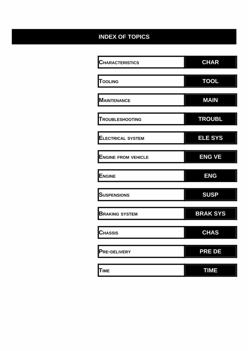
INDEX OF TOPICS
CHARACTERISTICS CHAR
TOOLING TOOL
MAINTENANCE MAIN
TROUBLESHOOTING TROUBL
ELECTRICAL SYSTEM ELE SYS
ENGINE FROM VEHICLE ENG VE
ENGINE ENG
SUSPENSIONS SUSP
BRAKING SYSTEM BRAK SYS
CHASSIS CHAS
PRE-DELIVERY PRE DE
TIME TIME

INDEX OF TOPICS
CHARACTERISTICS CHAR
Rules
This section describes general safety rules for any maintenance operations performed on the vehicle.
Safety rules
- If work can only be done on the vehicle with the engine running, make sure that the premises are well-
ventilated, using special extractors if necessary; never let the engine run in an enclosed area. Exhaust
fumes are toxic.
- The battery electrolyte contains sulphuric acid. Protect your eyes, clothes and skin. Sulphuric acid is
highly corrosive; in the event of contact with your eyes or skin, rinse thoroughly with abundant water
and seek immediate medical attention.
- The battery produces hydrogen, a gas that can be highly explosive. Do not smoke and avoid sparks
or flames near the battery, especially when charging it.
- Fuel is highly flammable and it can be explosive given some conditions. Do not smoke in the working
area, and avoid naked flames or sparks.
- Clean the brake pads in a well-ventilated area, directing the jet of compressed air in such a way that
you do not breathe in the dust produced by the wear of the friction material. Even though the latter
contains no asbestos, inhaling dust is harmful.
Maintenance rules
- Use original PIAGGIO spare parts and lubricants recommended by the Manufacturer. Non-original or
non-conforming spares may damage the vehicle.
- Use only the appropriate tools designed for this vehicle.
- Always use new gaskets, sealing rings and split pins upon refitting.
- After removal, clean the components using non-flammable or low flash-point solvents. Lubricate all
the work surfaces, except tapered couplings, before refitting these parts.
- After refitting, make sure that all the components have been installed correctly and work properly.
- For removal, overhaul and refit operations use only tools with metric measures. Metric bolts, nuts and
screws are not interchangeable with coupling members with English sizes. Using unsuitable coupling
members and tools may damage the scooter.
- When carrying out maintenance operations on the vehicle that involve the electrical system, make
sure the electric connections have been made properly, particularly the ground and battery connections.
Vespa LXV 50 Characteristics
CHAR - 7

Vehicle identification
VEHICLE IDENTIFICATIONSpecification Desc./QuantityEngine prefix C381M ÷ 1001Chassis prefix ZAPC38102 ÷ 1001
Dimensions and mass
WEIGHTS AND DIMENSIONSSpecification Desc./QuantityKerb weight 98 ± 5 kg
Overall height 1180 mmWheelbase 1280 mm
Length 1800 mmWidth 740 mm
Characteristics Vespa LXV 50
CHAR - 8
Engine
ENGINESpecification Desc./QuantityEngine type Two-stroke, single cylinder Piaggio Hi-PER2
Bore x stroke 40 X 39.3 mmCubic capacity 49.40 cc
Compression ratio 9.9 ±0.5 : 1Carburettor DELL'ORTO PHVA 17.5
Air filter Sponge impregnated with fuel mixture (50% SELENIA air filteroil and 50% unleaded petrol).
Engine idle speed ~ 1800 ± 100 rpmStarting system electric starter/kickstarter
Lubrication With blend and variable oil variable according to the enginerevolutions and the throttle valve opening by means of a pump
controlled by the driving shaft with toothed belt.Fuel supply Gravity feed, with unleaded petrol (with a minimum octane rat-
ing of 95) with carburettor.Cooling Forced air circulation.
Transmission
TRANSMISSIONSpecification Desc./QuantityTransmission With automatic expandable pulley variator, torque server, V
belt, automatic clutch, gear reduction unit.
Capacities
CAPACITYSpecification Desc./QuantityRear hub oil Quantity: approx. 85 ccoil mixer tank Plastic, capacity ~ 1.2 l
Fuel tank capacity ~ 8.5 l (2 l of which is reserve)
Electrical system
ELECTRICAL SYSTEMSpecification Desc./Quantity
Type of ignition Capacitive discharge type electronic ignition, with incorporatedhigh voltage coil
Ignition advance (before TDC) Fixed 17° ± 1Recommended spark plug CHAMPION RN2C
Battery 12V-4AhMain fuse 7.5 AGenerator In alternate current with three output sections
Frame and suspensions
FRAME AND SUSPENSIONSSpecification Desc./Quantity
Type Unitised body made of stamped plate
Vespa LXV 50 Characteristics
CHAR - 9
Specification Desc./QuantityFront suspension Single arm suspension with swinging arm articulated to the
steering tube. Hydraulic double-acting shock absorber and co-axial spring
Front suspension stroke 70 mmTrail (suspension rebounded/compressed) 71/68 mm
Rear suspension Single hydraulic double-acting shock absorber, helicoidal co-axial spring. Chassis engine support with swinging arm.
Rear suspension travel: 83.5 mm
Brakes
BRAKESSpecification Desc./QuantityFront brake Disc brake (Ø 200 mm) with hydraulic control (lever on the far
right of the handlebar) and fixed calliper.Rear brake Ø110 mm drum brake
Wheels and tyres
WHEELS AND TYRESSpecification Desc./QuantityFront tyre size 110/70"-11"Rear tyre size 120/70-10"
Front tyre pressure 1.6 barRear tyre pressure: 2 bar
Light alloy rims (Front rim) 2.50" x 11"Light alloy rims (rear rim) 3.00 x 10"
N.B.
CHECK AND ADJUST TYRE PRESSURE WITH TYRES AT AMBIENT TEMPERATURE. ADJUSTPRESSURE ACCORDING TO THE WEIGHT OF RIDER AND ACCESSORIES.
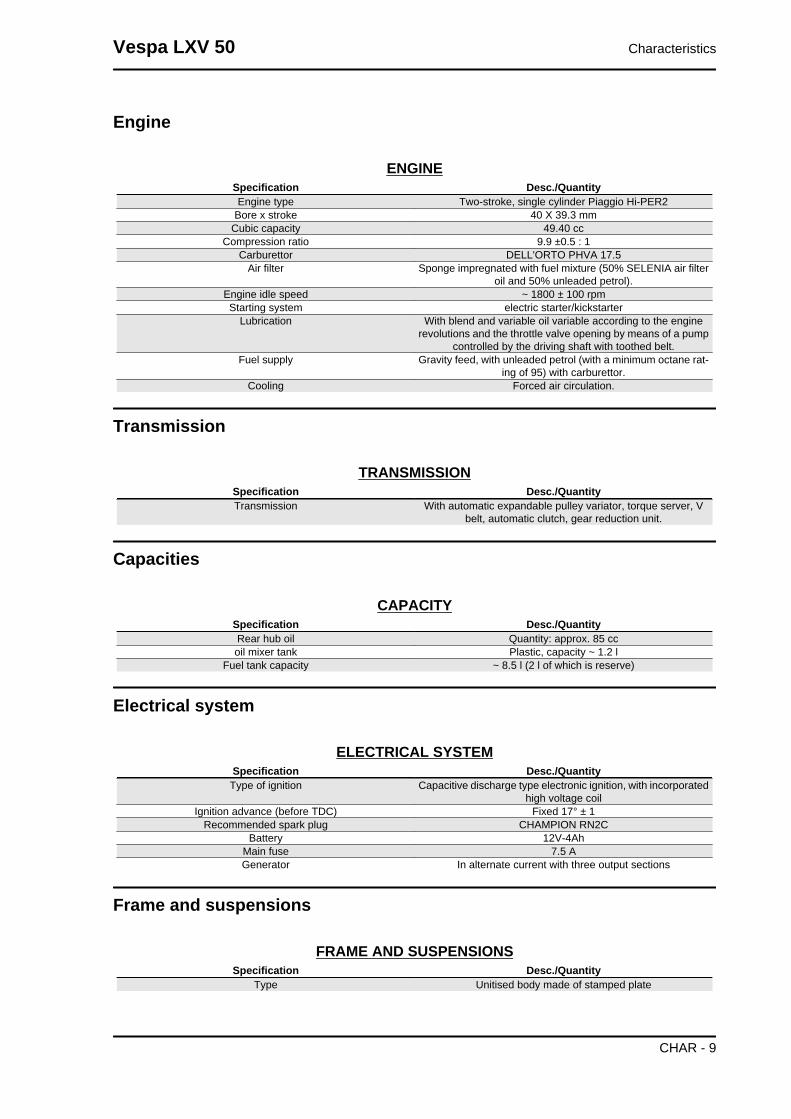
Secondary air
Follow these steps to clean the sponge filters of
the secondary air system:
1) Remove the snap-on plastic cover (1) on the
transmission cover using a small screwdriver as a
lever on the retaining tongues in order to insert one
of the three slots found on that cap.
2) Wash the polyurethane sponge with water and
soap, dry all components with compressed air and
refit to place. Refit the intake cap respecting the
angle reference.
3) Undo the two fixing screws (2) on the aluminium
cover of the secondary air housing in order to
reach the polyurethane sponge inside that hous-
ing; clean as indicated in point 2) and refit all
Characteristics Vespa LXV 50
CHAR - 10
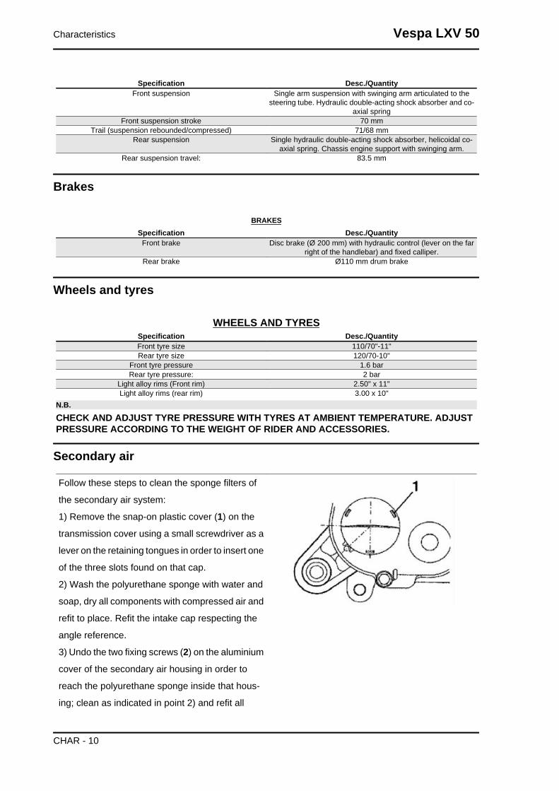
elements after checking the steel tab is not de-
formed and/or does not guarantee correct tight-
ness at its fitting; replace if necessary.N.B.UPON REFITTING, MAKE SURE TO CORRECTLY FIT THETAB IN ITS FITTING ON THE TWO PLASTIC AND ALUMI-NIUM COVERS.CAUTIONWHILE CARRYING OUT OPERATION 3), ALWAYS CHECKTHE TWO RUBBER COUPLINGS (3) ON ONE END OF THESECONDARY AIR PIPE FOR CORRECT TIGHTNESS ANDCONTINUITY; IF NECESSARY, REPLACE THEM AND USENEW CLAMPS TO FIX THEM.
Carburettor
50cc Version
Dell'Orto
DELLORTO CARBURETTORSpecification Desc./Quantity
Type PHVA 17.5 RDDiffuser diameter Ø 17.5
Regulation reference number 8444Maximum nozzle: 53
Maximum air nozzle (on the body): Ø 1.5Tapered pin stamped code: A22
Pin position (notches from above): 1Diffuser: 209 HA
Minimum nozzle: 32Minimum air nozzle (on the body): FreeInitial minimum mix screw opening: 1 1/2
Starter jet 50Starter air nozzle (on the body): Ø 1.5
Stroke of starter pin: 11 mmGasoline inlet hole Ø 1.5
Tightening Torques
FRONT BRAKEName Torque in Nm
Brake fluid pump-hose fitting 8 ÷ 12Brake fluid pipe-calliper fitting 20 ÷ 25
Screw tightening calliper to the support 20 ÷ 25Brake disc screw 5 ÷ 6.5
Oil bleed valve (on the calliper) 10 ÷ 12Handlebar pump 7 ÷ 10
FRONT SUSPENSIONName Torque in Nm
Shock absorber upper nut 20 ÷ 30Front wheel axle nut 75 ÷ 90
Shock absorber upper bracket bolts 20 ÷ 25
Vespa LXV 50 Characteristics
CHAR - 11

Name Torque in NmWheel rim screws 20 ÷ 25
Shock absorber lower bolts (°) 20 ÷ 27
STEERING ASSEMBLYName Torque in Nm
Steering upper ring nut 35 ÷ 40Steering lower ring nut 8 ÷ 10Handlebar fixing screw 50 ÷ 55
ENGINE ASSEMBLYName Torque in Nm
Clutch bell nut (**) 40 ÷ 44Clutch lock ring nut 55 ÷ 60
Nut locking driving pulley on crankshaft (**) 40 ÷ 44 NmStart-up lever screw 12 ÷ 13
Flywheel nut (**) 40 ÷ 44Flywheel fan screws 3 ÷ 4
Half-crank case joint bolts 12 ÷ 13Bolts holding exhaust pipe to the crankcase 22 ÷ 24
Screws holding the filter box to the crank case 4 ÷ 5Head nuts 10 ÷ 11
Starter screws 12 ÷ 13Ignition spark plug 25 ÷ 30
Hub oil drainage cap 3 ÷ 5Oil hub level dipstick ManualRear hub cap screws 12 ÷ 13
Transmission cover screws 12 ÷ 13Inlet manifold screws 8 ÷ 9
Flywheel hood fixing screws 1 ÷ 2Cylinder hood fixing screws 3.5 ÷ 5
Stator clamping screws 3 ÷ 4Pick-Up clamping screw 4 ÷ 5Mixer clamping screws 3 ÷ 4
Screw fixing brake lever to the journal on the engine 12 ÷ 13
FRAME ASSEMBLYName Torque in Nm
Swinging arm - engine pin* 33 ÷ 41Swinging arm pin - frame 44 ÷ 52
Shock absorber - chassis nut (*) 20 to 25 NmSwinging arm - frame plate 33 ÷ 41
shock absorber - engine pin (*) 33 to 41 N·mRear wheel nut 137 ÷ 152
Side stand fixing screw 12 ÷ 20Side stand bracket fixing screw 15 ÷ 20
Overhaul data
Assembly clearances
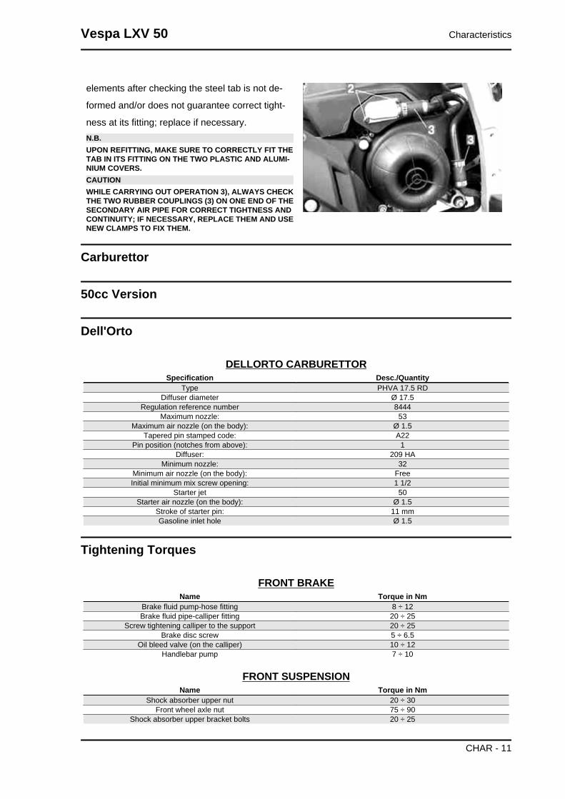
Cylinder - piston assy.
COUPLING BETWEEN PISTON AND CYLINDERName Initials Cylinder Piston Play on fitting
Standard coupling M 40.005 - 40.012 39.943 - 39.95 0.055 - 0.069Standard coupling N 40.012 - 40.019 39.95 - 39.957 0.055 - 0.069Standard coupling O 40.019 - 40.026 39.957 - 39.964 0.055 - 0.069Standard coupling P 40.026 - 40.033 39.964 - 39.971 0.055 - 0.069
Characteristics Vespa LXV 50
CHAR - 12
Name Initials Cylinder Piston Play on fittingcoupling 1st oversize M1 40.205 - 40.212 40.143 - 40.15 0.055 - 0.069coupling 1st oversize N1 40.212 - 40.219 40.15 - 40.157 0.055 - 0.069coupling 1st oversize O1 40.219 - 40.226 40.157 - 40.164 0.055 - 0.069coupling 1st oversize P1 40.226 - 40.233 40.164 - 40.171 0.055 - 0.069
Coupling 2nd oversize M2 40.405 - 40.412 40.343 - 40.35 0.055 - 0.069Coupling 2nd oversize N2 40.412 - 40.419 40.35 - 40.357 0.055 - 0.069Coupling 2nd oversize O2 40.419 - 40.426 40.357 - 40.364 0.055 - 0.069Coupling 2nd oversize P2 40.426 - 40.433 40.364 - 40.371 0.055 - 0.069
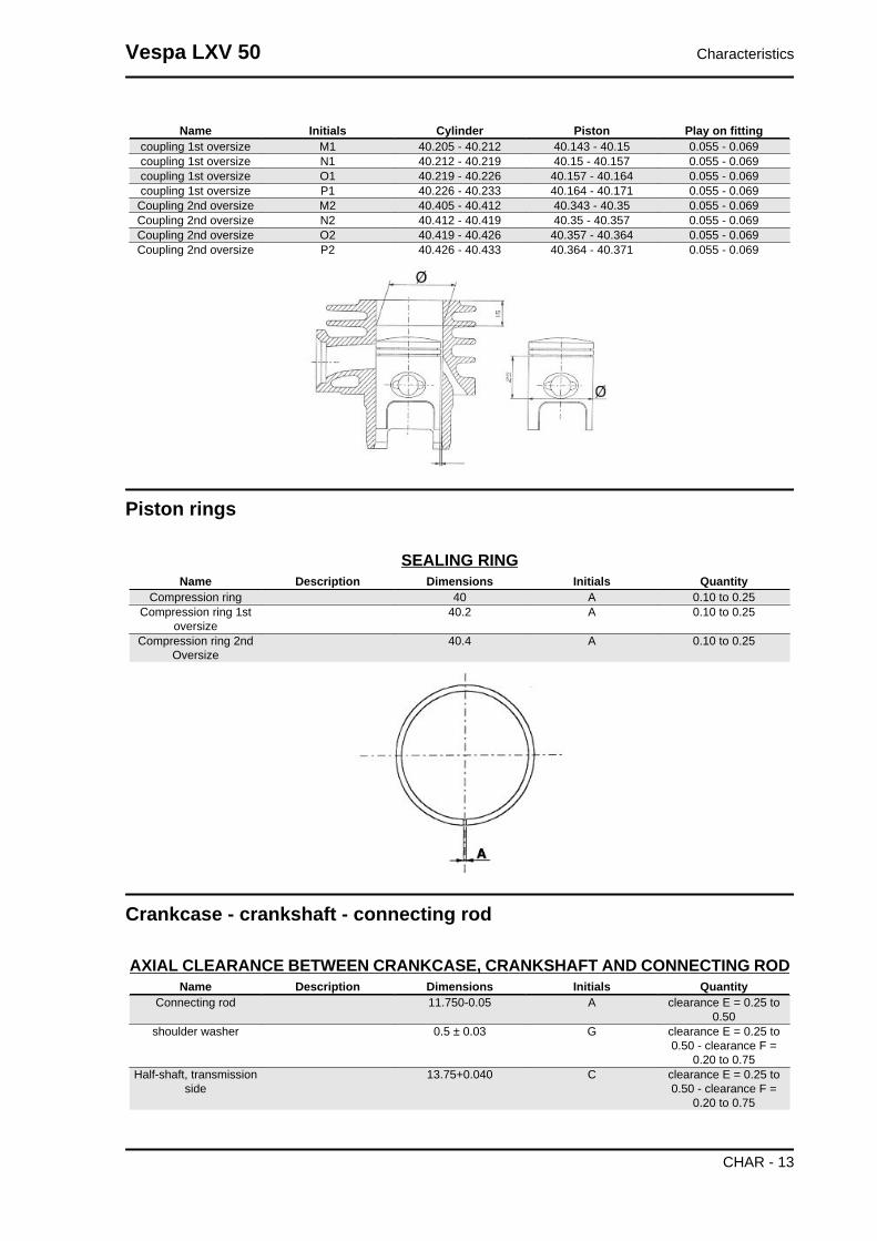
Piston rings
SEALING RINGName Description Dimensions Initials Quantity
Compression ring 40 A 0.10 to 0.25Compression ring 1st
oversize40.2 A 0.10 to 0.25
Compression ring 2ndOversize
40.4 A 0.10 to 0.25
Crankcase - crankshaft - connecting rod
AXIAL CLEARANCE BETWEEN CRANKCASE, CRANKSHAFT AND CONNECTING RODName Description Dimensions Initials Quantity
Connecting rod 11.750-0.05 A clearance E = 0.25 to0.50
shoulder washer 0.5 ± 0.03 G clearance E = 0.25 to0.50 - clearance F =
0.20 to 0.75Half-shaft, transmission
side13.75+0.040 C clearance E = 0.25 to
0.50 - clearance F =0.20 to 0.75
Vespa LXV 50 Characteristics
CHAR - 13
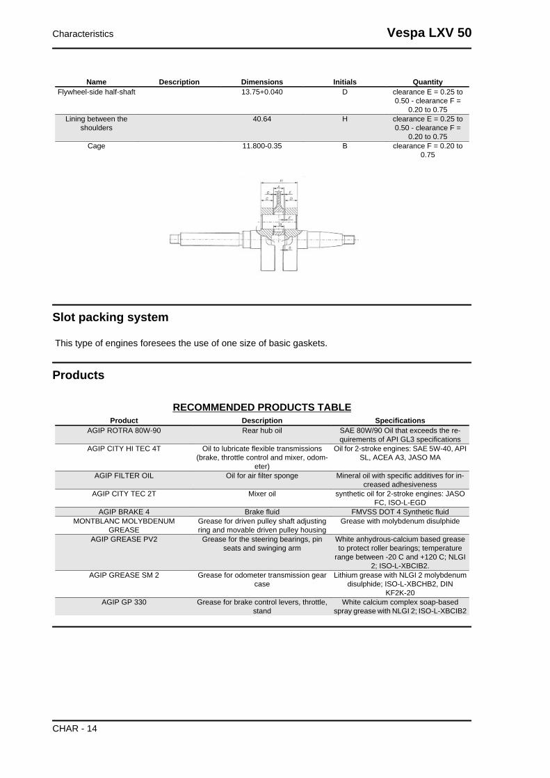
Name Description Dimensions Initials QuantityFlywheel-side half-shaft 13.75+0.040 D clearance E = 0.25 to
0.50 - clearance F =0.20 to 0.75
Lining between theshoulders
40.64 H clearance E = 0.25 to0.50 - clearance F =
0.20 to 0.75Cage 11.800-0.35 B clearance F = 0.20 to
0.75
Slot packing system
This type of engines foresees the use of one size of basic gaskets.
Products
RECOMMENDED PRODUCTS TABLEProduct Description Specifications
AGIP ROTRA 80W-90 Rear hub oil SAE 80W/90 Oil that exceeds the re-quirements of API GL3 specifications
AGIP CITY HI TEC 4T Oil to lubricate flexible transmissions(brake, throttle control and mixer, odom-
eter)
Oil for 2-stroke engines: SAE 5W-40, APISL, ACEA A3, JASO MA
AGIP FILTER OIL Oil for air filter sponge Mineral oil with specific additives for in-creased adhesiveness
AGIP CITY TEC 2T Mixer oil synthetic oil for 2-stroke engines: JASOFC, ISO-L-EGD
AGIP BRAKE 4 Brake fluid FMVSS DOT 4 Synthetic fluidMONTBLANC MOLYBDENUM
GREASEGrease for driven pulley shaft adjustingring and movable driven pulley housing
Grease with molybdenum disulphide
AGIP GREASE PV2 Grease for the steering bearings, pinseats and swinging arm
White anhydrous-calcium based greaseto protect roller bearings; temperature
range between -20 C and +120 C; NLGI2; ISO-L-XBCIB2.
AGIP GREASE SM 2 Grease for odometer transmission gearcase
Lithium grease with NLGI 2 molybdenumdisulphide; ISO-L-XBCHB2, DIN
KF2K-20AGIP GP 330 Grease for brake control levers, throttle,
standWhite calcium complex soap-based
spray grease with NLGI 2; ISO-L-XBCIB2
Characteristics Vespa LXV 50
CHAR - 14

INDEX OF TOPICS
TOOLING TOOL

TOOLSStores code Description
001330Y Tool for fitting steering seats
001467Y006 Pliers to extract 20 mm bearings
001467Y009 Driver for OD 42-mm bearings
001467Y013 Pliers to extract ø 15-mm bearings
001467Y014 Pliers to extract ø 15-mm bearings
001467Y017 Bell for bearings, OD 39 mm
002465Y Pliers for circlips
Tooling Vespa LXV 50
TOOL - 16

Stores code Description006029Y Punch for fitting fifth wheel seat on steer-
ing tube
020004Y Punch for removing fifth wheels fromheadstock
020055Y Wrench for steering tube ring nut
020150Y Air heater support
020151Y Air heater
020162Y Flywheel extractor
020163Y Crankcase splitting plate
Vespa LXV 50 Tooling
TOOL - 17

Stores code Description020166Y Pin lock fitting tool
020261Y Starter spring fitting
020265Y Bearing fitting base
020325Y Brake-shoe spring calliper
020329Y MityVac vacuum-operated pump
020330Y Stroboscopic light to check timing
Tooling Vespa LXV 50
TOOL - 18
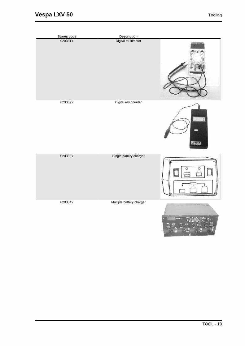
Stores code Description020331Y Digital multimeter
020332Y Digital rev counter
020333Y Single battery charger
020334Y Multiple battery charger
Vespa LXV 50 Tooling
TOOL - 19
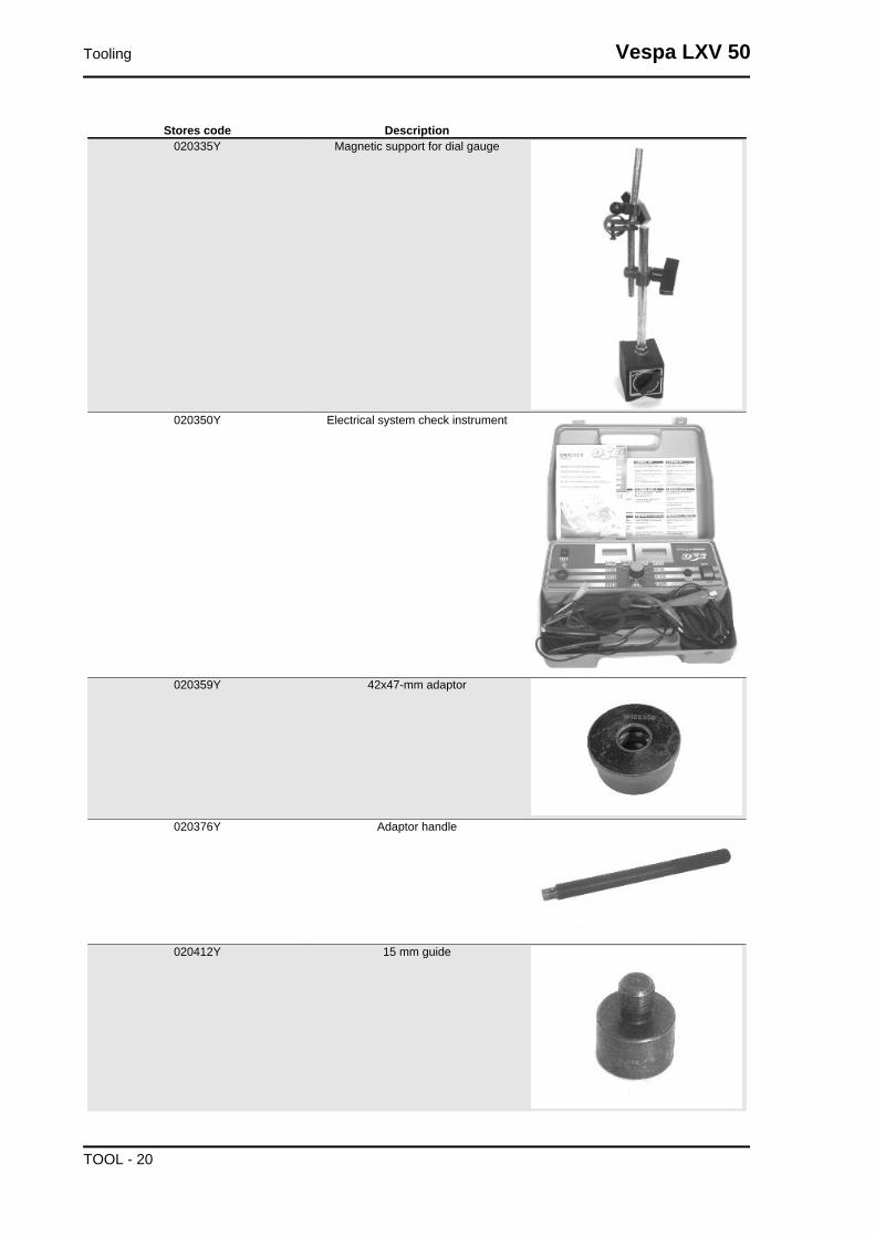
Stores code Description020335Y Magnetic support for dial gauge
020350Y Electrical system check instrument
020359Y 42x47-mm adaptor
020376Y Adaptor handle
020412Y 15 mm guide
Tooling Vespa LXV 50
TOOL - 20
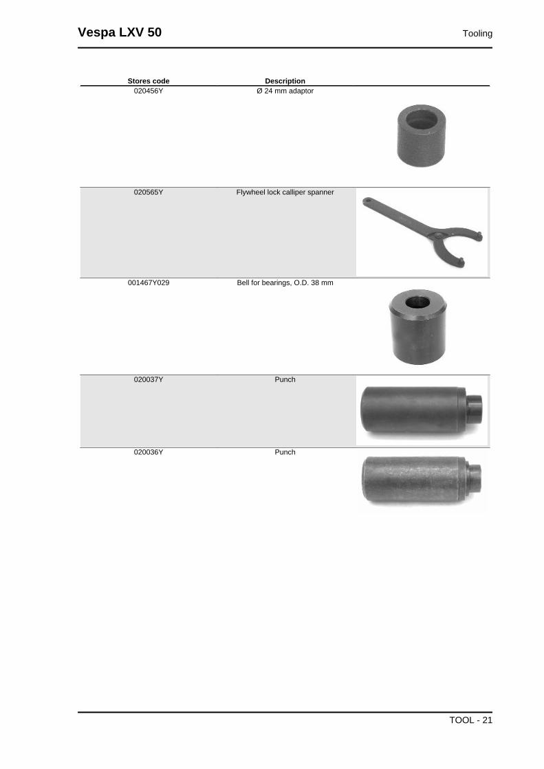
Stores code Description020456Y Ø 24 mm adaptor
020565Y Flywheel lock calliper spanner
001467Y029 Bell for bearings, O.D. 38 mm
020037Y Punch
020036Y Punch
Vespa LXV 50 Tooling
TOOL - 21

Stores code Description020021Y Front suspension service tool
020038Y Punch
020074Y Support base for checking crankshaftalignment
004499Y001 Bearing extractor bell
004499Y006 Bearing extractor ring
Tooling Vespa LXV 50
TOOL - 22
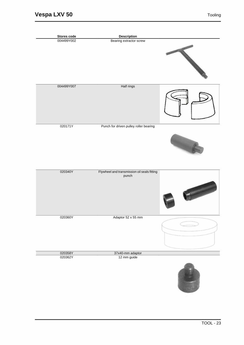
Stores code Description004499Y002 Bearing extractor screw
004499Y007 Half rings
020171Y Punch for driven pulley roller bearing
020340Y Flywheel and transmission oil seals fittingpunch
020360Y Adaptor 52 x 55 mm
020358Y 37x40-mm adaptor020362Y 12 mm guide
Vespa LXV 50 Tooling
TOOL - 23

Stores code Description020363Y 20 mm guide
020365Y 22 mm guide
020439Y 17 mm guide
020441Y 26 x 28 mm adaptor
020452Y Tube for removing and refitting the drivenpulley shaft
Tooling Vespa LXV 50
TOOL - 24

Stores code Description020451Y Starting ring gear lock
020444Y Tool for fitting/ removing the driven pulleyclutch
Vespa LXV 50 Tooling
TOOL - 25

INDEX OF TOPICS
MAINTENANCE MAIN

Maintenance chart
EVERY 2 YEARSAction
Brake fluid - change
AFTER 1000 KM50'
ActionHub oil - changeOil mixer/throttle linkage - adjustmentOdometer gear - greasingSteering - adjustmentBrake control levers - greasingBrake fluid level - checkSafety locks - checkElectrical system and battery - checkTyre pressure and wear - checkVehicle and brake test - road test
AFTER 5000 KM, 25000 KM, 35000 KM AND 55000 KM40'
ActionHub oil level - checkSpark plug/electrode gap - replacementAir filter - cleanOil mixer/throttle linkage - adjustmentBrake control levers - greasingBrake pads - check condition and wearBrake fluid level - checkElectrical system and battery - checkTyre pressure and wear - checkVehicle and brake test - road test
AFTER 10000 KM, 50000 KM95'
ActionHub oil - changeSpark plug/electrode gap - replacementAir filter - cleanIdle speed - adjustmentOil mixer/throttle linkage - adjustmentVariable speed rollers - replacementOdometer gear - greasingDriving belt - checkingSteering - adjustmentBrake control levers - greasingBrake pads - check condition and wearBrake fluid level - checkTransmission elements - lubricationSafety locks - checkSuspensions - checkElectrical system and battery - checkHeadlight - adjustmentTyre pressure and wear - checkVehicle and brake test - road test
AFTER 15000 KM AND 45000 KM
65'
Vespa LXV 50 Maintenance
MAIN - 27
ActionHub oil level - checkSpark plug/electrode gap - replacementAir filter - cleaningOil mixer/throttle linkage - adjustmentDriving belt - replacementBrake control levers - greasingBrake pads - check condition and wearBrake fluid level - checkElectrical system and battery - checkTyre pressure and wear - checkSAS box (sponge) (**) - cleaningVehicle and brake test - road test
(**) See regulations in the «Secondary air system» section
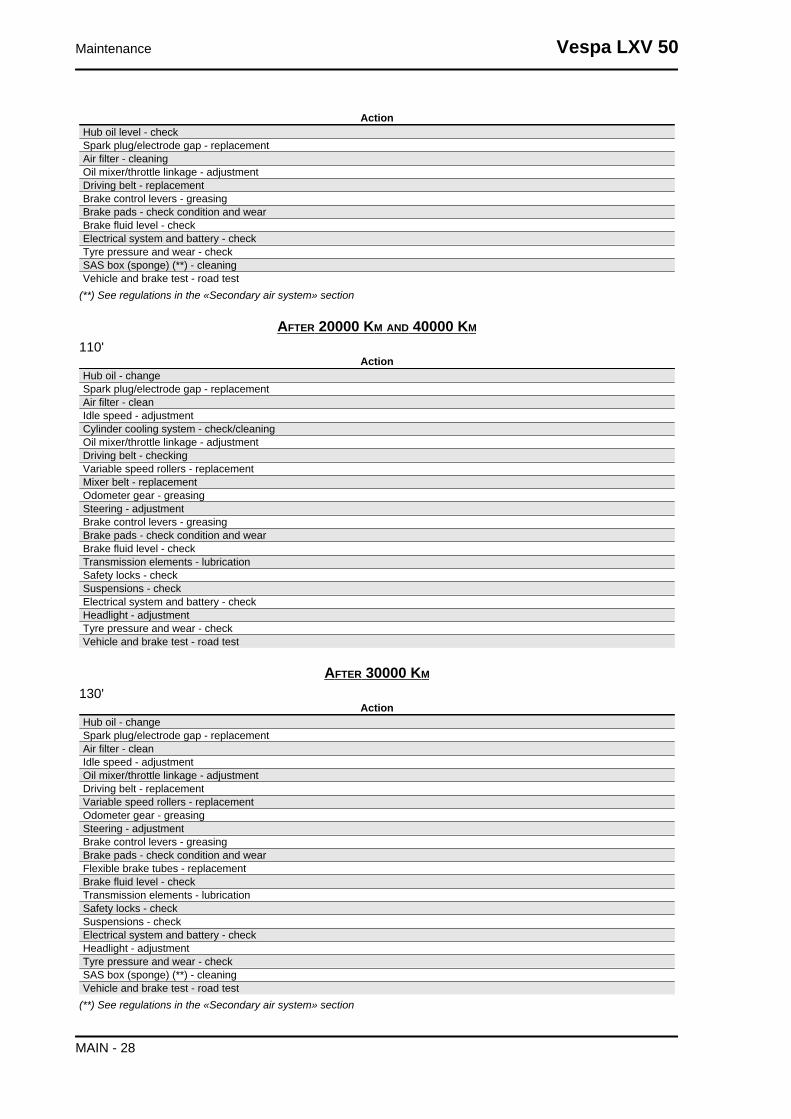
AFTER 20000 KM AND 40000 KM
110'Action
Hub oil - changeSpark plug/electrode gap - replacementAir filter - cleanIdle speed - adjustmentCylinder cooling system - check/cleaningOil mixer/throttle linkage - adjustmentDriving belt - checkingVariable speed rollers - replacementMixer belt - replacementOdometer gear - greasingSteering - adjustmentBrake control levers - greasingBrake pads - check condition and wearBrake fluid level - checkTransmission elements - lubricationSafety locks - checkSuspensions - checkElectrical system and battery - checkHeadlight - adjustmentTyre pressure and wear - checkVehicle and brake test - road test
AFTER 30000 KM
130'Action
Hub oil - changeSpark plug/electrode gap - replacementAir filter - cleanIdle speed - adjustmentOil mixer/throttle linkage - adjustmentDriving belt - replacementVariable speed rollers - replacementOdometer gear - greasingSteering - adjustmentBrake control levers - greasingBrake pads - check condition and wearFlexible brake tubes - replacementBrake fluid level - checkTransmission elements - lubricationSafety locks - checkSuspensions - checkElectrical system and battery - checkHeadlight - adjustmentTyre pressure and wear - checkSAS box (sponge) (**) - cleaningVehicle and brake test - road test
(**) See regulations in the «Secondary air system» section
Maintenance Vespa LXV 50
MAIN - 28

AFTER 60000 KM
150'Action
Hub oil - changeSpark plug/electrode gap - replacementAir filter - cleanIdle speed - adjustmentCylinder cooling system - check/cleaningOil mixer/throttle linkage - adjustmentDriving belt - replacementVariable speed rollers - replacementMixer belt - replacementOdometer gear - greasingSteering - adjustmentBrake control levers - greasingBrake pads - check condition and wearFlexible brake tubes - replacementBrake fluid level - checkTransmission elements - lubricationSafety locks - checkSuspensions - checkElectrical system and battery - checkHeadlight - adjustmentTyre pressure and wear - checkSAS box (sponge) (**) - cleaningVehicle and brake test - road test
(**) See regulations in the «Secondary air system» section
Carburettor
- Disassemble the carburettor in its parts, wash all
of them with solvent, dry all body grooves with
compressed air to ensure adequate cleaning.
- Check carefully that the parts are in good condi-
tion.
-The throttle valve should move freely in the
chamber. Replace valve in case of wear due to
excessive clearance.
- If there are wear marks in the chamber causing
inadequate tightness or a free valve slide (even if
it is new), replace the carburettor.
- It is advisable to replace the gaskets at every refit.WARNINGPETROL IS HIGHLY EXPLOSIVE ALWAYS REPLACE THEGASKETS TO AVOID PETROL LEAKS
1. Automatic starter - 2. Idle air set screw - 3. Idle speed set screw - 4. Throttle valve spring - 5. Throttle
valve tapered pin - 6. Throttle valve - 7. Carburettor body - 8. Pin - 9. Min. jet - 10. Float - 11. Max. jet
- 12. Float chamber
Vespa LXV 50 Maintenance
MAIN - 29

Checking the spark advance
-Check to be made at over 4000 rpm with strobo-
scopic gun. The advanced ignition measured must
be 17° before the TDC.
- This value is correct when the reference mark on
the flywheel hood is aligned with the reference
mark on the cooling fan and the phase shifter on
the stroboscopic gun is set on 17°.N.B.IN CASE OF MALFUNCTION, CARRY OUT THE CHECKSPROVIDED FOR IN THE ELECTRICAL SYSTEM CHAPTER.CAUTIONBEFORE CARRYING OUT THE ABOVE CHECKS, CHECKTHE CORRECT KEYING OF THE FLYWHEEL ON THECRANKSHAFT.
Specific tooling020330Y Stroboscopic light to check timing
Spark plug
Place the vehicle on its central stand
- Remove the central cover, indicated in the figure,
by undoing the 2 fixing screws;
- Disconnect spark plug HV wire hood;
-Undo the spark plug using the socket wrench;
-Examine the condition of the spark plug, check
that the insulating material is whole and measure
the distance between the electrodes using a thick-
ness gauge.
-Adjust the distance if necessary by bending the
side electrode very carefully.
In the case of defects, replace the spark plug with
one of the specified type;
- Engage the spark plug with the due inclination
and screw it right down by hand, then do it up with
the wrench at the prescribed torque;
-Put the hood on the sparking plug as far as it will
go;
Maintenance Vespa LXV 50
MAIN - 30

- Refit the central flap.CAUTIONTHE SPARK PLUG MUST BE REMOVED WHEN THE MO-TOR IS COLD. THE SPARK PLUG MUST BE REPLACEDEVERY 5000 KM. USE OF STARTERS NOT CONFORMINGOR SPARK PLUGS NOT THOSE DESCRIBED CAN SERI-OUSLY DAMAGE THE ENGINE.
CharacteristicRecommended spark plugCHAMPION RN2C
Electric characteristicElectrode gap0.6 to 0.7 mm.
Locking torques (N*m)Spark plug 25 - 30 Nm
Hub oil
Check
Do the following to check the correct level:
1) Stand the vehicle on the centre-stand on flat
ground;
2) Remove the dipstick «A», and dry it with a clean
cloth. Reinsert it, screwing it in all the way;
3) Remove the stick and check that the oil level is
slightly over the second notch starting from the
lower end;
4) Screw the dipstick back in, checking that it is
locked in place.
Recommended productsAGIP ROTRA 80W-90 Rear hub oilSAE 80W/90 Oil that exceeds the requirements of
API GL3 specifications
Vespa LXV 50 Maintenance
MAIN - 31

Replacement
-Remove the oil cap «A».
- Unscrew the oil drainage cap "B" and drain out
all the oil.
- Screw on the drainage plug and fill up the hub
with oil (about 85 cc)
Air filter
-Remove the cap of the purifier, unscrewing the six
clamping screws and removing the filter.
Cleaning:
-Wash with water and neutral soap.
- Dry with a clean cloth and short blasts of com-
pressed air.
-Saturate with a 50% mixture of gasoline and oil.
-Drip dry the filter and then squeeze it between the
hands without wringing.
-Let it dry and refit it again.CAUTIONNEVER RUN THE ENGINE WITHOUT THE AIR FILTER,THIS WOULD RESULT IN AN EXCESSIVE WEAR OF THEPISTON AND CYLINDER.
Recommended productsAGIP FILTER OIL Oil for air filter spongeMineral oil with specific additives for increased ad-
hesiveness
Maintenance Vespa LXV 50
MAIN - 32
Checking the ignition timing
- Adjust the control cables:
Mix cable: see procedure indicated in "Mixer tim-
ing".
Throttle cable: adjust the set screw on the carbu-
rettor in such a way that the sheath has no back-
lash.
Splitter control cable: adjust set screw on the throt-
tle control to the handlebar in such a way that there
is no backlash on the throttle control.
Adjust all transmissions in such a way that their
sheathings show no sign of backlash.
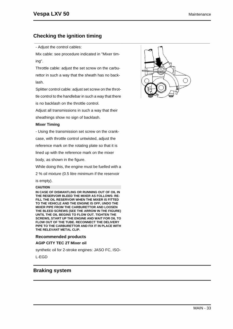
Mixer Timing
- Using the transmission set screw on the crank-
case, with throttle control untwisted, adjust the
reference mark on the rotating plate so that it is
lined up with the reference mark on the mixer
body, as shown in the figure.
While doing this, the engine must be fuelled with a
2 % oil mixture (0.5 litre minimum if the reservoir
is empty).CAUTIONIN CASE OF DISMANTLING OR RUNNING OUT OF OIL INTHE RESERVOIR BLEED THE MIXER AS FOLLOWS: RE-FILL THE OIL RESERVOIR WHEN THE MIXER IS FITTEDTO THE VEHICLE AND THE ENGINE IS OFF, UNDO THEMIXER PIPE FROM THE CARBURETTOR AND LOOSENTHE BLEED SCREWS (SEE THE ARROW IN THE FIGURE)UNTIL THE OIL BEGINS TO FLOW OUT. TIGHTEN THESCREWS, START UP THE ENGINE AND WAIT FOR OIL TOFLOW OUT OF THE TUBE. RECONNECT THE DELIVERYPIPE TO THE CARBURETTOR AND FIX IT IN PLACE WITHTHE RELEVANT METAL CLIP.
Recommended productsAGIP CITY TEC 2T Mixer oilsynthetic oil for 2-stroke engines: JASO FC, ISO-
L-EGD
Braking system
Vespa LXV 50 Maintenance
MAIN - 33

Level check
Proceed as follows:
- Rest the vehicle on its centre stand with the han-
dlebars perfectly horizontal;
- Check the level of liquid with the related warning
light «A».
A certain lowering of the level is caused by wear
on the pads.
Top-up
Proceed as follows:
- Remove the tank cap by loosening the two
screws, remove the gasket and top up using only
the liquid specified without exceeding the maxi-
mum level.CAUTIONONLY USE DOT 4-CLASSIFIED BRAKE FLUID.CAUTION
AVOID CONTACT OF THE BRAKE FLUID WITH YOUREYES, SKIN, AND CLOTHING. IN CASE OF ACCIDENTALCONTACT, WASH WITH WATER.CAUTIONBRAKING CIRCUIT FLUID IS HIGHLY CORROSIVE; MAKESURE THAT IT DOES NOT COME INTO CONTACT WITHTHE PAINTWORK.CAUTIONTHE BRAKE FLUID IS HYGROSCOPIC, IN OTHER WORDS,IT ABSORBS MOISTURE FROM THE SURROUNDING AIR.IF THE CONTENT OF MOISTURE IN THE BRAKING FLUIDEXCEEDS A CERTAIN VALUE, BRAKING WILL BE INEF-FICIENT.NEVER USE BRAKE LIQUID IN OPEN OR PARTIALLYUSED CONTAINERS.UNDER NORMAL CLIMATIC CONDITIONS, THE FLUIDMUST BE CHANGED EVERY 20,000 KM OR ANYWAY EV-ERY TWO YEARS.N.B.SEE THE BRAKING SYSTEM CHAPTER WITH REGARD TOTHE CHANGING OF BRAKE FLUID AND THE BLEEDINGOF AIR FROM THE CIRCUITS.
Recommended productsAGIP BRAKE 4 Brake fluidFMVSS DOT 4 Synthetic fluid
Maintenance Vespa LXV 50
MAIN - 34

Headlight adjustment
Proceed as follows:
1. Place the vehicle in running order and with the
tyres inflated to the prescribed pressure, on a flat
surface 10 m away from a white screen situated in
a shaded area, making sure that the longitudinal
axis of the scooter is perpendicular to the screen;
2. Turn on the headlight and check that the bor-
derline of the projected light beam on the screen
is not lower than 9/10 of the distance from the
ground to the centre of vehicle headlamp and high-
er than 7/10;
3. If it is, loosen the headlight support fixing screws
and adjust the headlight direction.N.B.THE ABOVE PROCEDURE COMPLIES WITH THE EURO-PEAN STANDARDS REGARDING MAXIMUM AND MINI-MUM HEIGHT OF LIGHT BEAMS. REFER TO THE STATU-TORY REGULATIONS IN FORCE IN EVERY COUNTRYWHERE THE vehicle IS USED.
SAS filters inspection and cleaning
Remove the right side fairing by undoing the 2
screws marked «B» indicated in the figure.
Remove the two screws «A» from the aluminium
SAS cover. Release the metal tube from the rub-
ber housing on the cover without extracting the
tube from the cover/sleeve. Remove the tab and
plastic cover, extract the sponge and wash it in
water and soap. Dry it with compressed air before
refitting it, making sure to correctly fit the tab in the
housing on the two plastic and aluminium covers.
Every time you disassemble the filter, replace the
O-ring seal located in the cover.
Vespa LXV 50 Maintenance
MAIN - 35

INDEX OF TOPICS
TROUBLESHOOTING TROUBL
This section makes it possible to find the solutions to use in troubleshooting.
For each breakdown, a list of the possible causes and respective interventions is given.
Engine
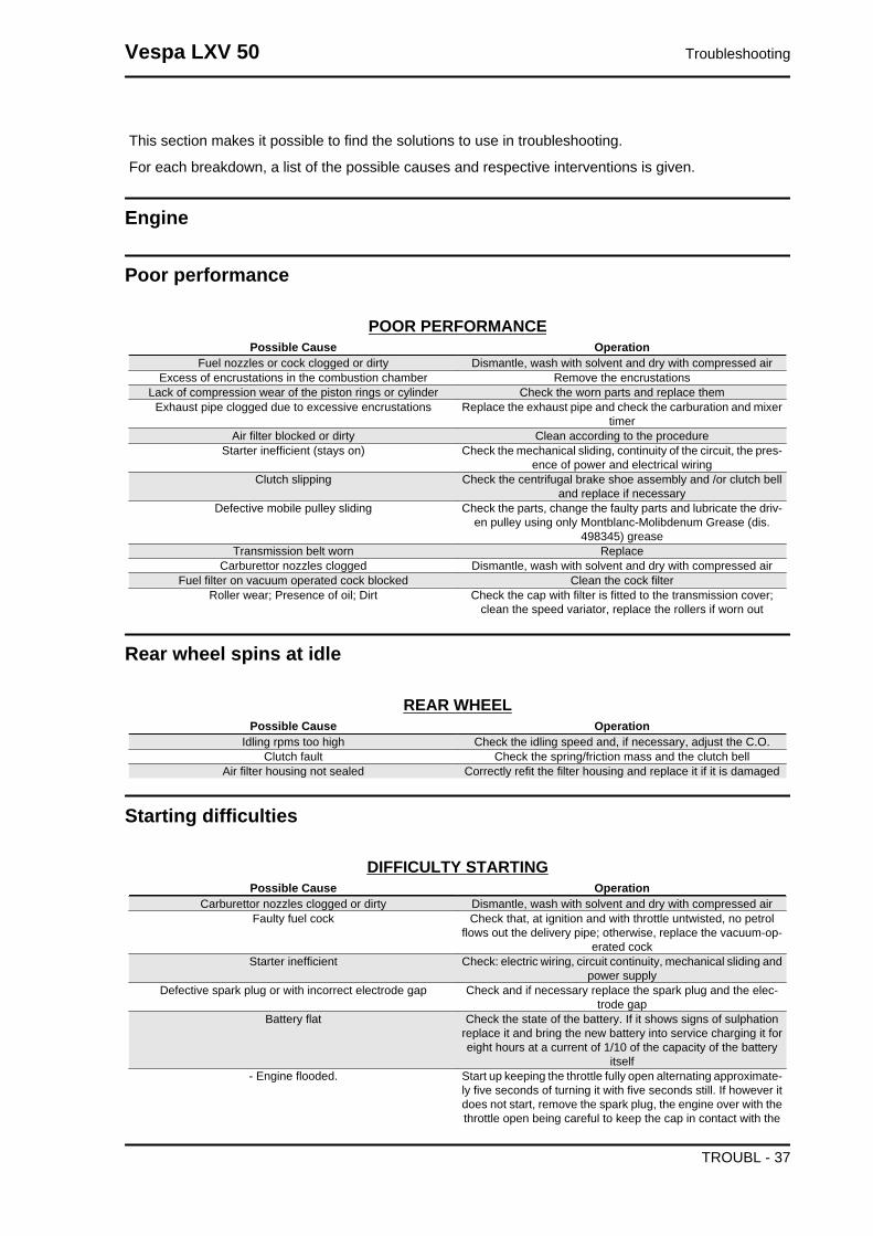
Poor performance
POOR PERFORMANCEPossible Cause Operation
Fuel nozzles or cock clogged or dirty Dismantle, wash with solvent and dry with compressed airExcess of encrustations in the combustion chamber Remove the encrustations
Lack of compression wear of the piston rings or cylinder Check the worn parts and replace themExhaust pipe clogged due to excessive encrustations Replace the exhaust pipe and check the carburation and mixer
timerAir filter blocked or dirty Clean according to the procedure
Starter inefficient (stays on) Check the mechanical sliding, continuity of the circuit, the pres-ence of power and electrical wiring
Clutch slipping Check the centrifugal brake shoe assembly and /or clutch belland replace if necessary
Defective mobile pulley sliding Check the parts, change the faulty parts and lubricate the driv-en pulley using only Montblanc-Molibdenum Grease (dis.
498345) greaseTransmission belt worn Replace
Carburettor nozzles clogged Dismantle, wash with solvent and dry with compressed airFuel filter on vacuum operated cock blocked Clean the cock filter
Roller wear; Presence of oil; Dirt Check the cap with filter is fitted to the transmission cover;clean the speed variator, replace the rollers if worn out
Rear wheel spins at idle
REAR WHEELPossible Cause Operation
Idling rpms too high Check the idling speed and, if necessary, adjust the C.O.Clutch fault Check the spring/friction mass and the clutch bell
Air filter housing not sealed Correctly refit the filter housing and replace it if it is damaged
Starting difficulties
DIFFICULTY STARTINGPossible Cause Operation
Carburettor nozzles clogged or dirty Dismantle, wash with solvent and dry with compressed airFaulty fuel cock Check that, at ignition and with throttle untwisted, no petrol
flows out the delivery pipe; otherwise, replace the vacuum-op-erated cock
Starter inefficient Check: electric wiring, circuit continuity, mechanical sliding andpower supply
Defective spark plug or with incorrect electrode gap Check and if necessary replace the spark plug and the elec-trode gap
Battery flat Check the state of the battery. If it shows signs of sulphationreplace it and bring the new battery into service charging it foreight hours at a current of 1/10 of the capacity of the battery
itself- Engine flooded. Start up keeping the throttle fully open alternating approximate-
ly five seconds of turning it with five seconds still. If however itdoes not start, remove the spark plug, the engine over with thethrottle open being careful to keep the cap in contact with the
Vespa LXV 50 Troubleshooting
TROUBL - 37
Possible Cause Operationspark plug and the spark plug grounded but away from its hole.
Refit a dry spark plug and start the vehicle.Altered fuel characteristics Drain off the fuel no longer up to standard; then, refill
Faulty spark plug Remove the encrustation, restore the plug gap or replace beingsure to use the types of spark plug recommended at all times.Bear in mind that many problems engines have, derive from
the use of the wrong spark plugIntake joint cracked or with a bad seal Replace intake joint and check for correct sealing on the head
Purifier-carburettor fitting damaged Replace
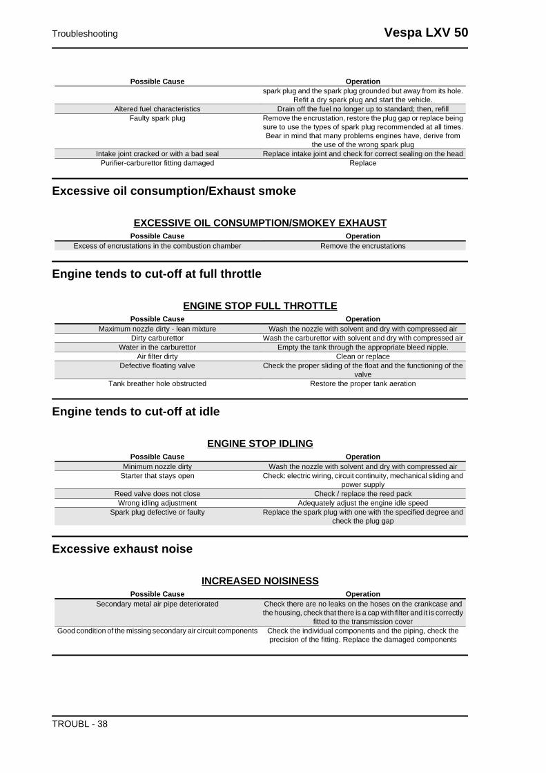
Excessive oil consumption/Exhaust smoke
EXCESSIVE OIL CONSUMPTION/SMOKEY EXHAUSTPossible Cause Operation
Excess of encrustations in the combustion chamber Remove the encrustations
Engine tends to cut-off at full throttle
ENGINE STOP FULL THROTTLEPossible Cause Operation
Maximum nozzle dirty - lean mixture Wash the nozzle with solvent and dry with compressed airDirty carburettor Wash the carburettor with solvent and dry with compressed air
Water in the carburettor Empty the tank through the appropriate bleed nipple.Air filter dirty Clean or replace
Defective floating valve Check the proper sliding of the float and the functioning of thevalve
Tank breather hole obstructed Restore the proper tank aeration
Engine tends to cut-off at idle
ENGINE STOP IDLINGPossible Cause Operation
Minimum nozzle dirty Wash the nozzle with solvent and dry with compressed airStarter that stays open Check: electric wiring, circuit continuity, mechanical sliding and
power supplyReed valve does not close Check / replace the reed packWrong idling adjustment Adequately adjust the engine idle speed
Spark plug defective or faulty Replace the spark plug with one with the specified degree andcheck the plug gap
Excessive exhaust noise
INCREASED NOISINESSPossible Cause Operation
Secondary metal air pipe deteriorated Check there are no leaks on the hoses on the crankcase andthe housing, check that there is a cap with filter and it is correctly
fitted to the transmission coverGood condition of the missing secondary air circuit components Check the individual components and the piping, check the
precision of the fitting. Replace the damaged components
Troubleshooting Vespa LXV 50
TROUBL - 38

High fuel consumption
HIGH FUEL CONSUMPTIONPossible Cause Operation
Air filter blocked or dirty. Clean according to the procedureStarter inefficient Check: electric wiring, circuit continuity, mechanical sliding and
power supply
SAS malfunctions
SLACKENING OF THE RUBBER JOINT OF THE SECONDARY AIR PIPE ON THE MUF-FLER
Possible Cause OperationSecondary air reed blocking ReplaceSecondary air filter clogging Clean the filter and the housing
Blockage of the secondary air fitting on the muffler Remove the encrustations from the joint being careful not to letthe debris fall into the muffler
Transmission and brakes
Clutch grabbing or performing inadequately
CLUTCH BRAKESPossible Cause Operation
Slippage or irregular functioning Check that the masses open and return normallyCheck that there is no grease on the masses
Check that the clutch masses' contact surface with the clutchbell is mainly in the middle with characteristics equivalent on
the three massesCheck that the clutch bell is not scored or worn abnormally
Never operate the engine without the clutch bellCheck the cap with filter is fitted to the transmission cover
Insufficient braking
BRAKING SYSTEM MALFUNCTIONPossible Cause Operation
Poor braking The rear (drum type) brake is adjusted by regulating the specialadjustment (on the wheel) bearing in mind that, with the control
levers in the rest position, the wheels must turn freely.The braking action should begin when the brake levers are
pressed by about a third.Check the brake pad wear.
If it is not possible to remove any problems by simply adjustingthe transmissions, check the brake pads and front brake disc,the brake shoes and the rear drum. If you encounter excessive
wear or scoring, make the necessary replacements.Air bubbles inside the hydraulic braking system Carefully bleed the hydraulic braking system, (there must be
no flexible movement of the brake lever).Fluid leakage in hydraulic braking system Elastic fittings, piston seals or brake pump breakdown, replace
The brake fluid has lost its properties Replace the front brake fluid and top up to the correct level inthe pump
Defective sliding of the cables in their sheathes Lubricate or substituteBrake noise Check the wear of the brake pads and/or shoes
Vespa LXV 50 Troubleshooting
TROUBL - 39

Brakes overheating
BRAKES OVERHEATINGPossible Cause Operation
Defective piston sliding Check calliper and replace any damaged part.Brake disc or drum deformed Using a dial gauge, check the planarity of the disk with the
wheel correctly fitted or the concentricity of the rear drum.
Electrical system
Battery
BATTERYPossible Cause Operation
Battery The battery is the electrical device in the system that requiresthe most frequent inspections and thorough maintenance. If thevehicle is not used for some time (1 month or more) the battery
needs to be recharged periodically. The battery runs downcompletely in the course of 5 ÷ 6 months. If the battery is fittedon a motorcycle, be careful not to invert the connections, keep-
ing in mind that the black ground wire is connected to thenegative terminal while the red wire is connected to the terminalmarked+. Follow the instructions in the ELECTRICAL SYSTEM
chapter for the recharging of the batteries.
Steering and suspensions
Heavy steering
STEERING HARDENINGPossible Cause Operation
Torque not conforming Check the tightening of the top and bottom ring nuts.If irregularities continue in turning the steering even after mak-ing the above adjustments, check the seats in which the ball
bearings rotate: replace if they are recessed.
Excessive steering play
EXCESSIVE STEERING CLEARANCEPossible Cause Operation
EXCESSIVE STEERING CLEARANCE Check the tightening of the top and bottom ring nuts.If irregularities continue in turning the steering even after mak-ing the above adjustments, check the seats in which the ball
bearings rotate: replace if they are recessed.
Noisy suspension
NOISY SUSPENSIONPossible Cause Operation
NOISY SUSPENSION If the front suspension is noisy, check: the efficiency of the frontshock absorbers; the condition of the ball bearings and relevant
Troubleshooting Vespa LXV 50
TROUBL - 40
Possible Cause Operationlock-nuts, the limit switch rubber buffers and the movement
bushings.
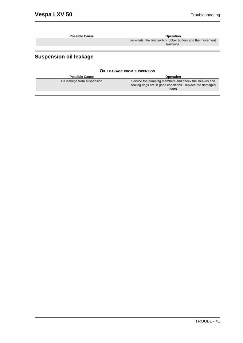
Suspension oil leakage
OIL LEAKAGE FROM SUSPENSIONPossible Cause Operation
Oil leakage from suspension Service the pumping members and check the sleeves andsealing rings are in good conditions. Replace the damaged
parts
Vespa LXV 50 Troubleshooting
TROUBL - 41
INDEX OF TOPICS
ELECTRICAL SYSTEM ELE SYS

KEY:
1. Electronic ignition device
2. Spark plug
3. Magneto flywheel
4. Voltage regulator
5. Main fuse
6. Key switch
7. Battery
8. Starter motor
9. Starter remote control
10. Starter button
11. STOP button on front brake
12. STOP button on rear brake
13. Horn button
14. Horn
15. Left turn rear indicator lamp
16. Rear headlight assembly with tail light and stop light bulbs
17. Turn indicator switch
18. Right turn rear indicator lamp
19. Left turn front indicator lamp
Vespa LXV 50 Electrical system
ELE SYS - 43

20. Front headlight assembly with high- and low-beam bulb
A. Tail light bulb
B. Low-/high-beam light bulb
21. Right turn front indicator lamp
22. Light switch
23. High-beam light flash switch
24. Fuel level warning light control
25. Instrument panel
A. turn indicator warning light
B. Fuel level warning light
C. Oil mix level warning light
D. fuel gauge
E. Instrument panel lighting
F. High-beam warning light
G. headlight warning light
H. turn indicator warning light
26. Low oil warning light control
27. Automatic starter
28. Carburettor heater
29. Carburettor heater control device
Ar = Orange, Az = Sky Blue, Bi = White, Bl = Blue, Gi = Yellow, Gr = Grey, Ma = Brown, Ne = Black,
Ro = Pink, Rs = Red, Ve = Green, Vi = Purple
Conceptual diagrams
Electrical system Vespa LXV 50
ELE SYS - 44

Ignition
KEY:
1. Electronic ignition device
2. Spark plug
3. Magneto flywheel
6. Key switch
Vespa LXV 50 Electrical system
ELE SYS - 45

Headlights and automatic starter section
KEY:
3. Magneto flywheel
4. Voltage regulator
5. Main fuse
6. Key switch
7. Battery
16. Rear headlight assembly with tail light and stop light bulbs
20. Front headlight assembly with high- and low-beam bulb
A. Tail light bulb
B. Low-/high-beam light bulb
22. Light switch
23. High-beam light flash switch
25. Instrument panel
A. turn indicator warning light
B. Fuel level warning light
C. Oil mix level warning light
D. fuel gauge
E. Instrument panel lighting
Electrical system Vespa LXV 50
ELE SYS - 46
F. High-beam warning light
G. headlight warning light
H. turn indicator warning light
27. Automatic starter
28. Carburettor heater
29. Carburettor heater control device
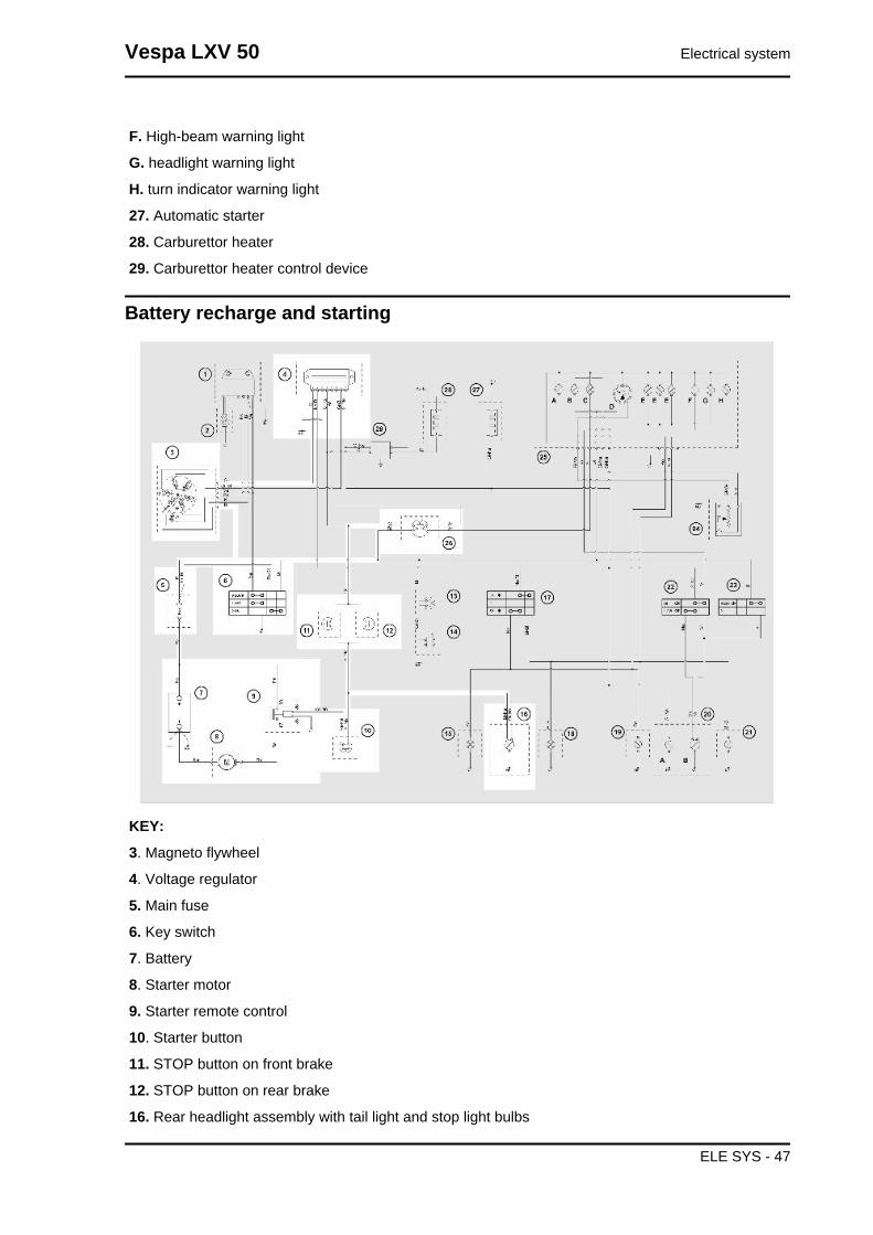
Battery recharge and starting
KEY:
3. Magneto flywheel
4. Voltage regulator
5. Main fuse
6. Key switch
7. Battery
8. Starter motor
9. Starter remote control
10. Starter button
11. STOP button on front brake
12. STOP button on rear brake
16. Rear headlight assembly with tail light and stop light bulbs
Vespa LXV 50 Electrical system
ELE SYS - 47
26. Low oil warning light control
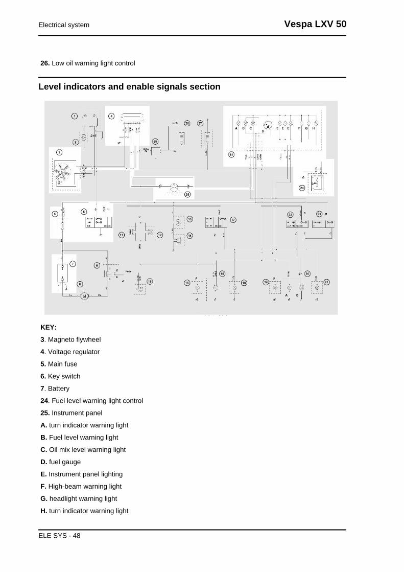
Level indicators and enable signals section
KEY:
3. Magneto flywheel
4. Voltage regulator
5. Main fuse
6. Key switch
7. Battery
24. Fuel level warning light control
25. Instrument panel
A. turn indicator warning light
B. Fuel level warning light
C. Oil mix level warning light
D. fuel gauge
E. Instrument panel lighting
F. High-beam warning light
G. headlight warning light
H. turn indicator warning light
Electrical system Vespa LXV 50
ELE SYS - 48
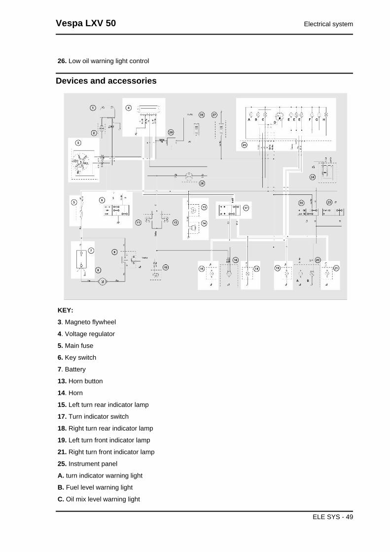
26. Low oil warning light control
Devices and accessories
KEY:
3. Magneto flywheel
4. Voltage regulator
5. Main fuse
6. Key switch
7. Battery
13. Horn button
14. Horn
15. Left turn rear indicator lamp
17. Turn indicator switch
18. Right turn rear indicator lamp
19. Left turn front indicator lamp
21. Right turn front indicator lamp
25. Instrument panel
A. turn indicator warning light
B. Fuel level warning light
C. Oil mix level warning light
Vespa LXV 50 Electrical system
ELE SYS - 49

D. fuel gauge
E. Instrument panel lighting
F. High-beam warning light
G. headlight warning light
H. turn indicator warning light
Checks and inspections
All the control operations of the system that entail disconnecting cables (to check connections and the
devices making up the ignition circuit) must be done with the engine off: if this is not done, the controls
might be irreparably damaged.
Ignition circuit
1) Check the condition of the spark plug (clean it
with a metal brush, remove deposits,
blast it with a jet of compressed air and replace it
if necessary).
2) Without removing the stator, carry out the fol-
lowing checks:
After visually checking the electrical wiring, per-
form measurements on the loading coil, the pickup
and the continuity using the appropriate tester.
If checks on the loading reel, pickup and continuity
show abnormalities, replace the stator; otherwise
replace the central unit.
Remember that disconnections due to replace-
ment of the central unit must be done with the
engine off.
Specific tooling020331Y Digital multimeter
PICK-UP CHECKSpecification Desc./Quantity
1 Red cable (1) and White cable (2) 90 ÷ 140 Ohm
RELOADING COIL CHECKSpecification Desc./Quantity
1 Red cable (3) and Green cable (4) 800 ÷ 1100 Ohm
Electrical system Vespa LXV 50
ELE SYS - 50

CONTINUITY CHECKSpecification Desc./Quantity
1 White cable - Engine Continuity2 White cable - Frame Continuity
Voltage regulator check
Voltage regulator
The malfunctioning of the voltage regulator might
cause the following problems depending on the
type of fault:
1) Lighting system bulbs burn out.
2) Lighting system is not working.
3) Battery overcharges (the main fuse blows).
4) Battery not recharging.
5) Turn indicators not working.
6) Oil and fuel check warning light not working.
Remedies
FAULT 1: Bulbs burn out
Check that the control voltage is between 13V and
14.5V at 5000 rpm with the lights on.
Check that the control voltage is <16V at 5000 rpm
with the lights off.
Replace the voltage regulator if control voltages
are over >16V.
FAULT 2: Lighting system not working
a) Check that voltage to stator is correctly sup-
plied: disconnect the regulator connector and
place the tester to detect alternating voltages be-
tween the connection of the grey-blue cable (2)
and the black cable (6) to check that the voltage
supplied at 3000 r/1' is within 25 - 30 V as indicated
in the figure. If faults are detected, replace the sta-
tor.
b) If no faults are detected with these controls, re-
place the regulator.
c) If functioning is still not correct even when the
regulator has been replaced, check the connec-
tions of the electrical system.
Vespa LXV 50 Electrical system
ELE SYS - 51
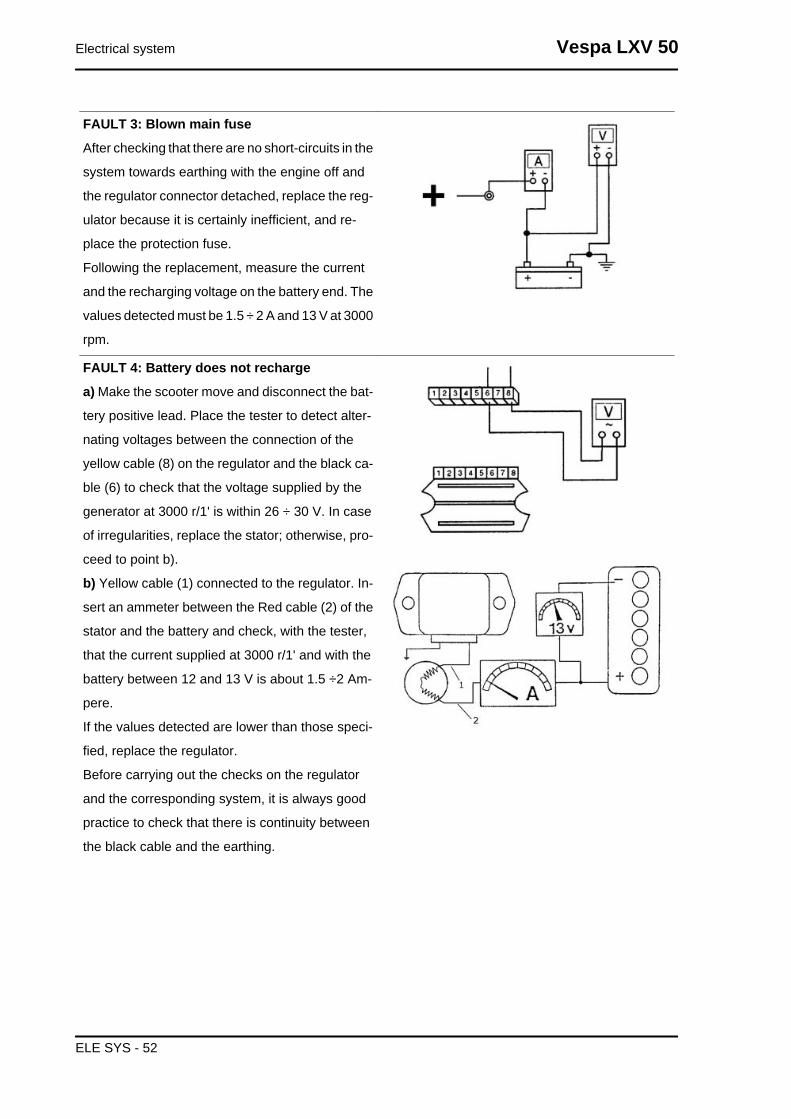
FAULT 3: Blown main fuse
After checking that there are no short-circuits in the
system towards earthing with the engine off and
the regulator connector detached, replace the reg-
ulator because it is certainly inefficient, and re-
place the protection fuse.
Following the replacement, measure the current
and the recharging voltage on the battery end. The
values detected must be 1.5 ÷ 2 A and 13 V at 3000
rpm.
FAULT 4: Battery does not recharge
a) Make the scooter move and disconnect the bat-
tery positive lead. Place the tester to detect alter-
nating voltages between the connection of the
yellow cable (8) on the regulator and the black ca-
ble (6) to check that the voltage supplied by the
generator at 3000 r/1' is within 26 ÷ 30 V. In case
of irregularities, replace the stator; otherwise, pro-
ceed to point b).
b) Yellow cable (1) connected to the regulator. In-
sert an ammeter between the Red cable (2) of the
stator and the battery and check, with the tester,
that the current supplied at 3000 r/1' and with the
battery between 12 and 13 V is about 1.5 ÷2 Am-
pere.
If the values detected are lower than those speci-
fied, replace the regulator.
Before carrying out the checks on the regulator
and the corresponding system, it is always good
practice to check that there is continuity between
the black cable and the earthing.
Electrical system Vespa LXV 50
ELE SYS - 52

FAULT 5: Turn indicators not working
If the turn indicators do not work, do the following:
Remove the regulator connector, and insert the
ends of the tester between contact 5 (yellow) and
the earthing.
- Turn the key switch to ON and check that the
battery is getting voltage. If no voltage is detected,
check the wiring and the contacts on the key
switch and on the battery.
Repeat the same procedure with the ends of the
tester inserted between contact 5 (yellow) and 6
(black) and check there is voltage in the battery
with the key switch set to ON. If there is no voltage,
check the cable harness.
If the above tests have positive results, jump the
contacts 5 (yellow) and 7 (blue black) on the con-
nector, set the key switch to ON and turn the turn
indicator switch left and right to see when the lights
are steadily on (as they are powered directly from
the battery). If even after this operation the turn
indicators fail to turn on, check the wiring is not
damaged and switch works properly; If these last
two tests have a positive result, replace the regu-
lator because it is certainly not functioning proper-
ly.
FAULT 6:Oil reserve check warning light not
working
Disconnect the voltage regulator connector.
- Supply 12V to the terminal marked with number
5; with a digital tester check that the terminal num-
ber 4 has a similar output (12V) for about 5 sec-
onds.
- If no voltage is detected for terminal number 4,
replace the regulator.
Vespa LXV 50 Electrical system
ELE SYS - 53
- If there is voltage for terminal number 4, check
both the cable harness and the bulb of the oil
warning light.
Specific tooling020331Y Digital multimeter
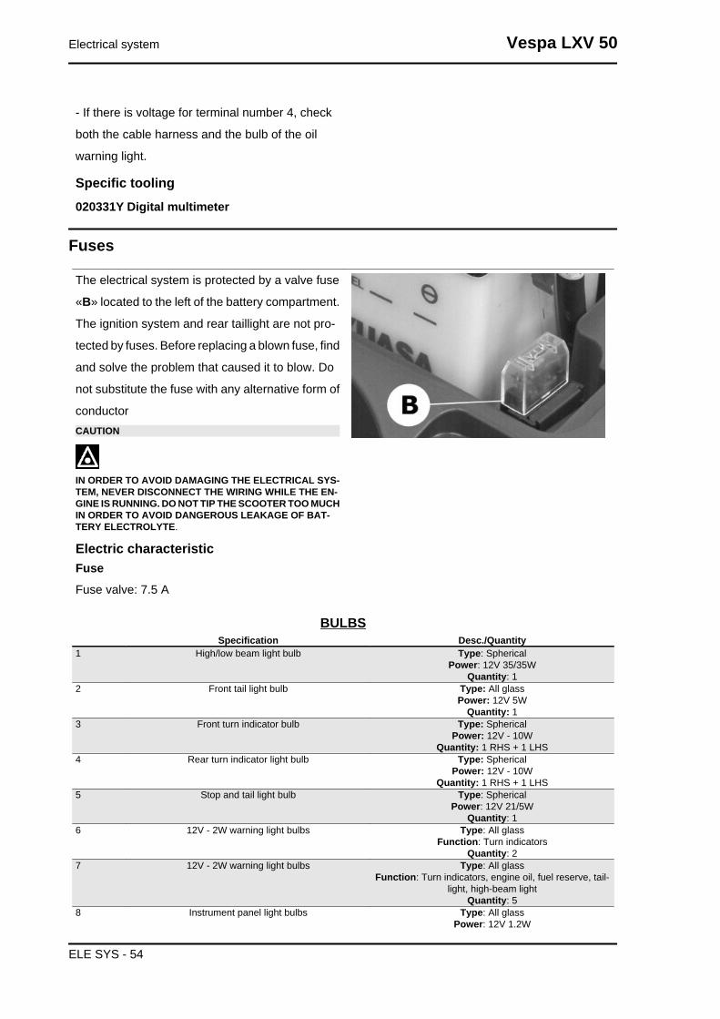
Fuses
The electrical system is protected by a valve fuse
«B» located to the left of the battery compartment.
The ignition system and rear taillight are not pro-
tected by fuses. Before replacing a blown fuse, find
and solve the problem that caused it to blow. Do
not substitute the fuse with any alternative form of
conductorCAUTION
IN ORDER TO AVOID DAMAGING THE ELECTRICAL SYS-TEM, NEVER DISCONNECT THE WIRING WHILE THE EN-GINE IS RUNNING. DO NOT TIP THE SCOOTER TOO MUCHIN ORDER TO AVOID DANGEROUS LEAKAGE OF BAT-TERY ELECTROLYTE.
Electric characteristicFuseFuse valve: 7.5 A
BULBSSpecification Desc./Quantity
1 High/low beam light bulb Type: SphericalPower: 12V 35/35W
Quantity: 12 Front tail light bulb Type: All glass
Power: 12V 5WQuantity: 1
3 Front turn indicator bulb Type: SphericalPower: 12V - 10W
Quantity: 1 RHS + 1 LHS4 Rear turn indicator light bulb Type: Spherical
Power: 12V - 10WQuantity: 1 RHS + 1 LHS
5 Stop and tail light bulb Type: SphericalPower: 12V 21/5W
Quantity: 16 12V - 2W warning light bulbs Type: All glass
Function: Turn indicatorsQuantity: 2
7 12V - 2W warning light bulbs Type: All glassFunction: Turn indicators, engine oil, fuel reserve, tail-
light, high-beam lightQuantity: 5
8 Instrument panel light bulbs Type: All glassPower: 12V 1.2W
Electrical system Vespa LXV 50
ELE SYS - 54
Specification Desc./QuantityQuantity: 4
Sealed battery
INSTRUCTIONS FOR REFRESHING THE STOCK CHARGE OF AN OPEN CIRCUIT
1) Voltage check
Before installing the battery on the vehicle, check the open circuit voltage with a normal tester.
- If the voltage exceeds 12.60 V, the battery may be installed without any renewal recharge.
- If voltage is below 12.60 V, a renewal recharge is required as explained in 2).
2) Constant voltage battery charge mode
-Constant voltage equal to 14.40÷14.70V
-Initial charge voltage equal to 0.3÷0.5 for nominal capacity
-Duration of the charge: 10 to 12 h recommended
Minimum 6 h
Maximum 24 h
3) Constant current battery charge mode
-Charge current equal to 1/10 of the nominal capacity of the battery
-Duration of the charge: 5 hWARNING
-WHEN THE BATTERY IS REALLY FLAT (WELL BELOW 12.6V) IT MIGHT BE THAT 5 HOURS OFRECHARGING ARE NOT ENOUGH TO ACHIEVE OPTIMAL PERFORMANCE.IN THESE CONDITIONS IT IS HOWEVER ESSENTIAL NOT TO EXCEED EIGHT HOURS OF CON-TINUOUS RECHARGING SO AS NOT TO DAMAGE THE BATTERY ITSELF.
Dry-charge batteryWARNING
- Battery electrolyte is toxic and it may cause serious burns. It contains sulphuric acid. Avoid contactwith eyes, skin and clothing. In case of contact with eyes or skin, flush abundantly with water for about15 minutes and seek immediate medical attention.In the event of accidental ingestion of the fluid, immediately drink large quantities of water or milk. Followwith milk of magnesia, beaten egg or vegetable oil. Seek immediate medical attentionBatteries produce explosive gases; keep clear of free flames, sparks or cigarettes; ventilate the areawhen recharging the battery indoors.Always protect your eyes when working close to batteries.Keep out of the reach of children.
Vespa LXV 50 Electrical system
ELE SYS - 55

The battery is an electrical device which requires
careful monitoring and diligent maintenance. The
maintenance rules are:
1) Check the level of the electrolyte
The electrolyte level must be checked frequently
and must reach the upper level. Only use distilled
water, to restore this level.
If it is necessary to add water too frequently, check
the vehicle's electrical system: the battery works
overcharged and is subject to quick wear.
2)Load status check
After restoring the electrolyte level, check its den-
sity using an appropriate densitometer (see the
figure).
When the battery is charged, you should detect a
density of 30 to 32 Bé corresponding to a specific
weight of 1.26 to 1.28 at a temperature of no lower
than 15° C.
A density reading of less than 20° Bé indicates that
the battery is completely flat and it must therefore
be recharged.
After charging the battery, check each element
electrolyte level and density. If the scooter is not
used for a given time (1 month or more) it will be
necessary to periodically recharge the battery.
The battery runs down completely in the course of
three months.
If it is necessary to refit the battery in the vehicle,
be careful not to reverse the connections, remem-
bering that the earth wire (black) marked (-) must
be connected to the - negative terminal while the
other two red wires marked (+) must be connected
to the terminal marked with the + positive sign.
Regular bench charging must be carried out with
the specific battery charger, (single) or (multiple),
setting the battery charger selector to the type of
battery to be recharged. Connections to the power
Electrical system Vespa LXV 50
ELE SYS - 56

supply source must be implemented by connect-
ing the corresponding poles (+ to+ and - to -).
4) Cleaning the battery
The battery should always be kept clean, espe-
cially on its top side, and the terminals should be
coated with Vaseline.WARNING- Before recharging the battery, remove the plugs of each cell.Keep the battery away from naked flames or sparks whencharging.Remove the battery from the vehicle removing the negativeclamp first.CAUTIONNEVER USE FUSES WITH A CAPACITY HIGHER THANTHAT RECOMMENDED.USING A FUSE OF UNSUITABLE RATING MAY SERIOUS-LY DAMAGE THE VEHICLE OR EVEN CAUSE A FIRE.CAUTIONDRINKING WATER CONTAINS MINERALS THAT CAN BEEXTREMELY HARMFUL TO THE BATTERY: USE DISTIL-LED WATER ONLY.CAUTIONTO ENSURE MAXIMUM PERFORMANCE THE BATTERYMUST BE CHARGED BEFORE USE.INADEQUATE CHARGING OF THE BATTERY WITH A LOWELECTROLYTE LEVEL BEFORE IT IS FIRST USEDSHORTENS THE LIFE OF THE BATTERY.
Specific tooling020333Y Single battery charger
020334Y Multiple battery charger
1)- Remove the short closed tube and the caps, then pour sulphuric acid into the cells using the type
specified for batteries, with a specific gravity of 1.26, corresponding to 30° Bé, at a minimum temperature
of 15°C until the upper level is reached.
2) - Leave to rest for at least 2 hours; then, restore the level with sulphuric acid.
3)- Within the following 24 hours, recharge with the specific battery charger (single) or (multiple) at a
density of about 1/10 of the battery nominal capacity and until the acid density is about 1.27, corre-
sponding to 31º Bé, and these values are stabilised.
4) - Once the charge is over, level the acid (by adding distilled water). Close and clean carefully.
5)- Once the above operations have been performed, install the battery in the vehicle ensuring the
connections between the wiring and the battery terminals are correct.WARNING- ONCE THE BATTERY HAS BEEN INSTALLED IN THE VEHICLE IT IS NECESSARY TO REPLACETHE SHORT TUBE (WITH CLOSED END) NEAR THE + POSITIVE TERMINAL WITH THE CORRE-SPONDING LONG TUBE (WITH OPEN END), THAT YOU FIND FITTED TO THE VEHICLE, TOENSURE THAT THE GASES THAT FORM CAN ESCAPE PROPERLY.
Specific tooling020333Y Single battery charger
Vespa LXV 50 Electrical system
ELE SYS - 57

020334Y Multiple battery charger
Electrical system Vespa LXV 50
ELE SYS - 58

INDEX OF TOPICS
ENGINE FROM VEHICLE ENG VE
Removal of the engine from the vehicleRemoving the engine from the chassis
-Disconnect the battery.
-Remove the muffler assembly.
- Remove the rear wheel.
- Remove the mechanical transmission of the rear brake.
-Disconnect the electric terminals.
- Remove the throttle grip and mixer transmissions.
- Disconnect the hoses (petrol-oil-vacuum-operated cock control).WARNING
Be very careful when handling fuel.CAUTION
When installing the battery, first attach the positive cable and then the negative cable.WARNING
Wear safety goggles when using hitting tools.
Engine from vehicle Vespa LXV 50
ENG VE - 60
INDEX OF TOPICS
ENGINE ENG

Automatic transmission
Transmission cover
- Loosen the 15 screws and remove the transmis-
sion cover with the aid of a mallet.N.B.THE CRANKCASE IS SLIGHTLY BLOCKED BY THE TIGHTFIT BETWEEN THE SHAFT OF THE DRIVEN HALF-PULLEYAND THE BEARING HOUSED ON THE CRANKCASE.
Kickstart
- Remove the screws shown in the figure and re-
move the engine starting lever.
- For the assembly, work in reverse and tighten the
screws to the prescribed torque..
Locking torques (N*m)Starter lever replacement 12 to 13 Nm
- Upon refitting, apply the recommended grease to
the bushing, to the spring and along the toothed
sector.
- Use the special tool for the charging of the spring,
as shown in the figure.
- Refit the seeger ring after checking that it is in
good condition.
Specific tooling020261Y Starter spring fitting
Recommended productsAGIP GREASE MU3 Grease for odometertransmission gear caseSoap-based lithium grease with NLGI 3; ISO-L-
XBCHA3, DIN K3K-20
Engine Vespa LXV 50
ENG - 62
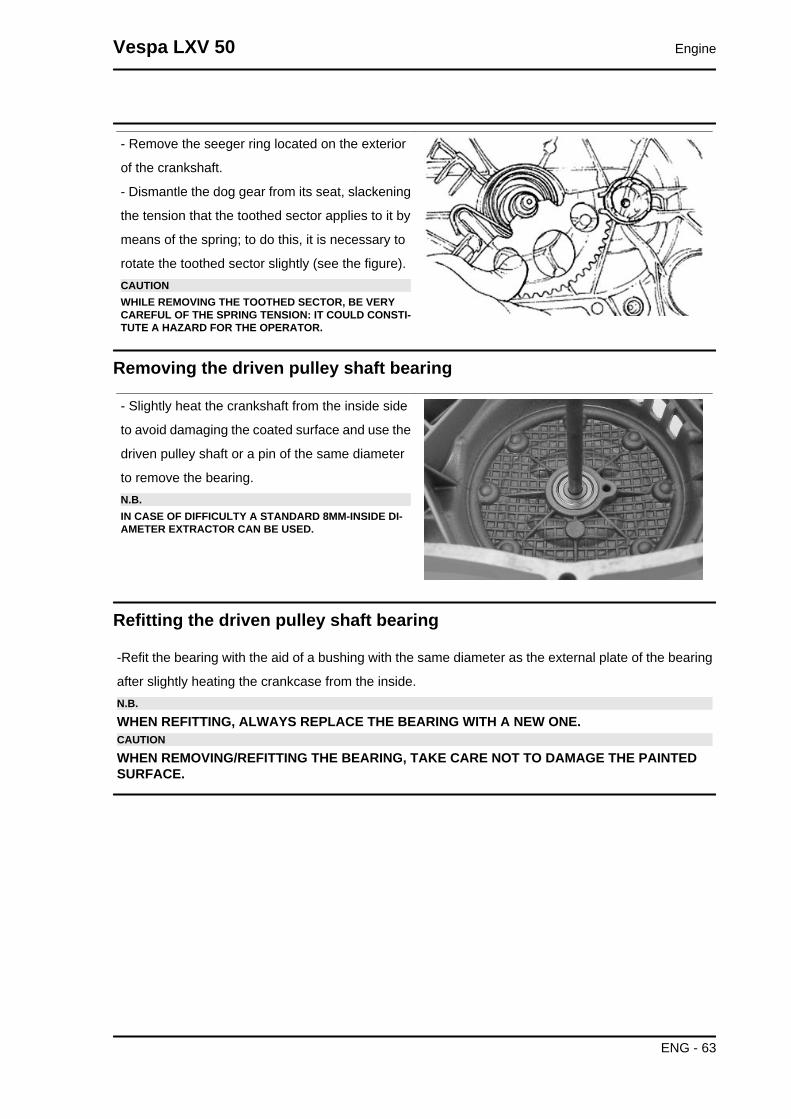
- Remove the seeger ring located on the exterior
of the crankshaft.
- Dismantle the dog gear from its seat, slackening
the tension that the toothed sector applies to it by
means of the spring; to do this, it is necessary to
rotate the toothed sector slightly (see the figure).CAUTIONWHILE REMOVING THE TOOTHED SECTOR, BE VERYCAREFUL OF THE SPRING TENSION: IT COULD CONSTI-TUTE A HAZARD FOR THE OPERATOR.
Removing the driven pulley shaft bearing
- Slightly heat the crankshaft from the inside side
to avoid damaging the coated surface and use the
driven pulley shaft or a pin of the same diameter
to remove the bearing.N.B.IN CASE OF DIFFICULTY A STANDARD 8MM-INSIDE DI-AMETER EXTRACTOR CAN BE USED.
Refitting the driven pulley shaft bearing
-Refit the bearing with the aid of a bushing with the same diameter as the external plate of the bearing
after slightly heating the crankcase from the inside.N.B.
WHEN REFITTING, ALWAYS REPLACE THE BEARING WITH A NEW ONE.CAUTION
WHEN REMOVING/REFITTING THE BEARING, TAKE CARE NOT TO DAMAGE THE PAINTEDSURFACE.
Vespa LXV 50 Engine
ENG - 63
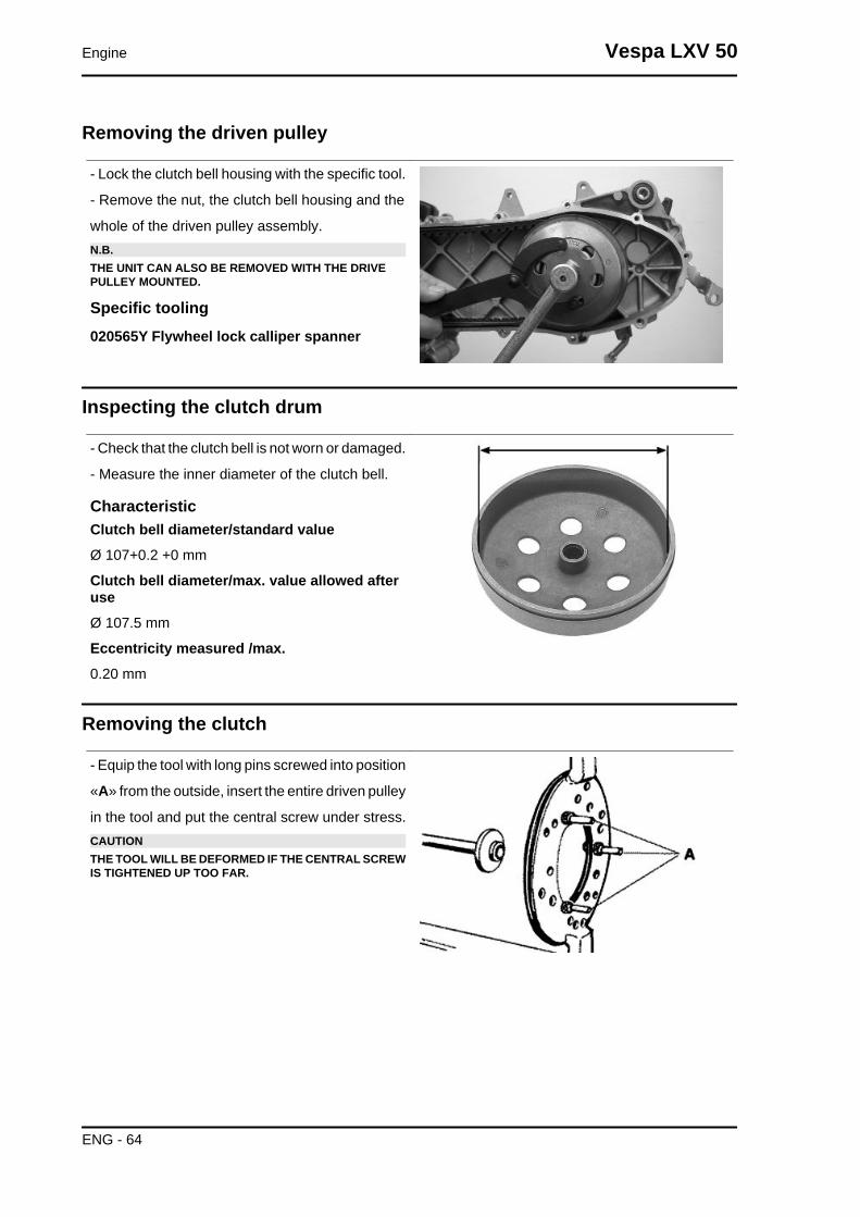
Removing the driven pulley
- Lock the clutch bell housing with the specific tool.
- Remove the nut, the clutch bell housing and the
whole of the driven pulley assembly.N.B.THE UNIT CAN ALSO BE REMOVED WITH THE DRIVEPULLEY MOUNTED.
Specific tooling020565Y Flywheel lock calliper spanner
Inspecting the clutch drum
- Check that the clutch bell is not worn or damaged.
- Measure the inner diameter of the clutch bell.
CharacteristicClutch bell diameter/standard valueØ 107+0.2 +0 mm
Clutch bell diameter/max. value allowed afteruseØ 107.5 mm
Eccentricity measured /max.0.20 mm
Removing the clutch
- Equip the tool with long pins screwed into position
«A» from the outside, insert the entire driven pulley
in the tool and put the central screw under stress.CAUTIONTHE TOOL WILL BE DEFORMED IF THE CENTRAL SCREWIS TIGHTENED UP TOO FAR.
Engine Vespa LXV 50
ENG - 64

- Using a 34 mm socket wrench remove the clutch
locking nut.
- Loosen the central screw thereby undoing the
driven pulley unit
- Separate the components.
Specific tooling020444Y Tool for fitting/ removing the drivenpulley clutch
Inspecting the clutch
- Check the thickness of the clutch mass friction
material.
- The masses must not show traces of lubricants;
otherwise, check the driven pulley unit seals.N.B.UPON RUNNING-IN, THE MASSES MUST EXHIBIT A CEN-TRAL CONTACT SURFACE AND MUST NOT BE DIFFER-ENT FROM ONE ANOTHER.VARIOUS CONDITIONS CAN CAUSE THE CLUTCH TOTEAR.CAUTIONDO NOT OPEN THE MASSES USING TOOLS TO PREVENTA VARIATION IN THE RETURN SPRING LOAD.
CharacteristicCheck minimum thickness1 mm
Pin retaining collar
- Remove the collar with the aid of 2 screwdrivers.
Vespa LXV 50 Engine
ENG - 65

- Remove the three guide pins and the mobile half
pulley.
Removing the driven half-pulley bearing
- Remove the roller bearing with the special ex-
tractor inserted from the bottom of the fixed half-
pulley.CAUTIONPOSITION THE HOLDING EDGE OF THE EXTRACTION PLI-ERS BETWEEN THE END OF THE BEARING AND THEBUILT IN SEALING RING.
Specific tooling001467Y029 Bell for bearings, O.D. 38 mm
- Remove the ball bearing retention snap ring.
- Expel the ball bearing from the side of the clutch
housing by means of the special tool.N.B.PROPERLY SUPPORT THE HALF-PULLEY SO AS NOT TODEFORM THE SLIDING SURFACE OF THE DRIVING BELT
Specific tooling020376Y Adaptor handle
020363Y 20 mm guide
Inspecting the driven fixed half-pulley
- Check that there are no signs of wear on the work
surface of the belt. If there are, replace the half-
pulley..
- Make sure the bearings do not show signs of un-
usual wear.
- Measure the external diameter of the pulley bush-
ing.
Characteristic
Engine Vespa LXV 50
ENG - 66

Stationary driven half-pulley/Standard diame-terØ 33.965 to 33.985 mm
Stationary driven half-pulley / Minimum diam-eter admitted after useØ 33.96 mm
Inspecting the driven sliding half-pulley
- Remove the 2 inner sealing rings and the two O-
rings.
- Measure the inside diameter of the mobile half-
pulley bushing.
CharacteristicMobile driven half-pulley/ Maximum diameterallowedØ 34.08 mm
- Check the belt contact surfaces.
- Insert the new oil seal and O-rings on the mobile
half-pulley.
- Fitting the half-pulley on the bushing.
Recommended productsAGIP GREASE SM 2 Grease for the tone wheelrevolving ringSoap-based lithium grease containing NLGI 2 Mo-
lybdenum disulphide; ISO-L-XBCHB2, DIN
KF2K-20
- Make sure the pins and collar are not worn, reassemble the pins and collar.
- Use a greaser with a curved spout to lubricate the driven pulley unit with around 6 gr. of grease. This
operation must be done through one of the holes inside the bushing until grease comes out of the
opposite hole. This procedure is necessary to prevent the presence of grease beyond the O-ring.
Recommended productsAGIP GREASE SM 2 Grease for the tone wheel revolving ring
Soap-based lithium grease containing NLGI 2 Molybdenum disulphide; ISO-L-XBCHB2, DIN KF2K-20
Vespa LXV 50 Engine
ENG - 67
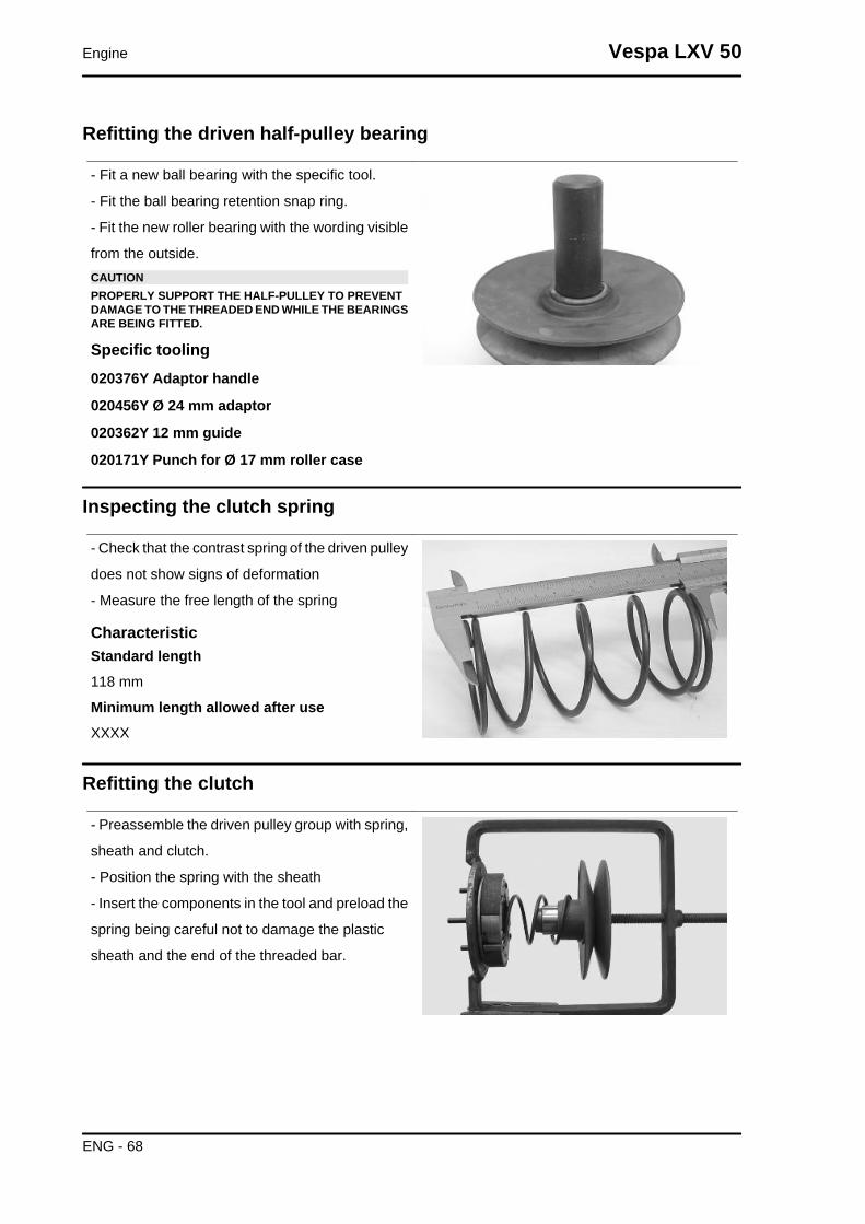
Refitting the driven half-pulley bearing
- Fit a new ball bearing with the specific tool.
- Fit the ball bearing retention snap ring.
- Fit the new roller bearing with the wording visible
from the outside.CAUTIONPROPERLY SUPPORT THE HALF-PULLEY TO PREVENTDAMAGE TO THE THREADED END WHILE THE BEARINGSARE BEING FITTED.
Specific tooling020376Y Adaptor handle
020456Y Ø 24 mm adaptor
020362Y 12 mm guide
020171Y Punch for Ø 17 mm roller case
Inspecting the clutch spring
- Check that the contrast spring of the driven pulley
does not show signs of deformation
- Measure the free length of the spring
CharacteristicStandard length118 mm
Minimum length allowed after useXXXX
Refitting the clutch
- Preassemble the driven pulley group with spring,
sheath and clutch.
- Position the spring with the sheath
- Insert the components in the tool and preload the
spring being careful not to damage the plastic
sheath and the end of the threaded bar.
Engine Vespa LXV 50
ENG - 68
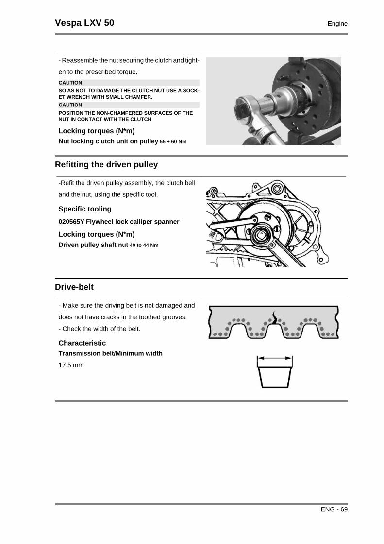
- Reassemble the nut securing the clutch and tight-
en to the prescribed torque.CAUTIONSO AS NOT TO DAMAGE THE CLUTCH NUT USE A SOCK-ET WRENCH WITH SMALL CHAMFER.CAUTIONPOSITION THE NON-CHAMFERED SURFACES OF THENUT IN CONTACT WITH THE CLUTCH
Locking torques (N*m)Nut locking clutch unit on pulley 55 ÷ 60 Nm
Refitting the driven pulley
-Refit the driven pulley assembly, the clutch bell
and the nut, using the specific tool.
Specific tooling020565Y Flywheel lock calliper spanner
Locking torques (N*m)Driven pulley shaft nut 40 to 44 Nm
Drive-belt
- Make sure the driving belt is not damaged and
does not have cracks in the toothed grooves.
- Check the width of the belt.
CharacteristicTransmission belt/Minimum width17.5 mm
Vespa LXV 50 Engine
ENG - 69
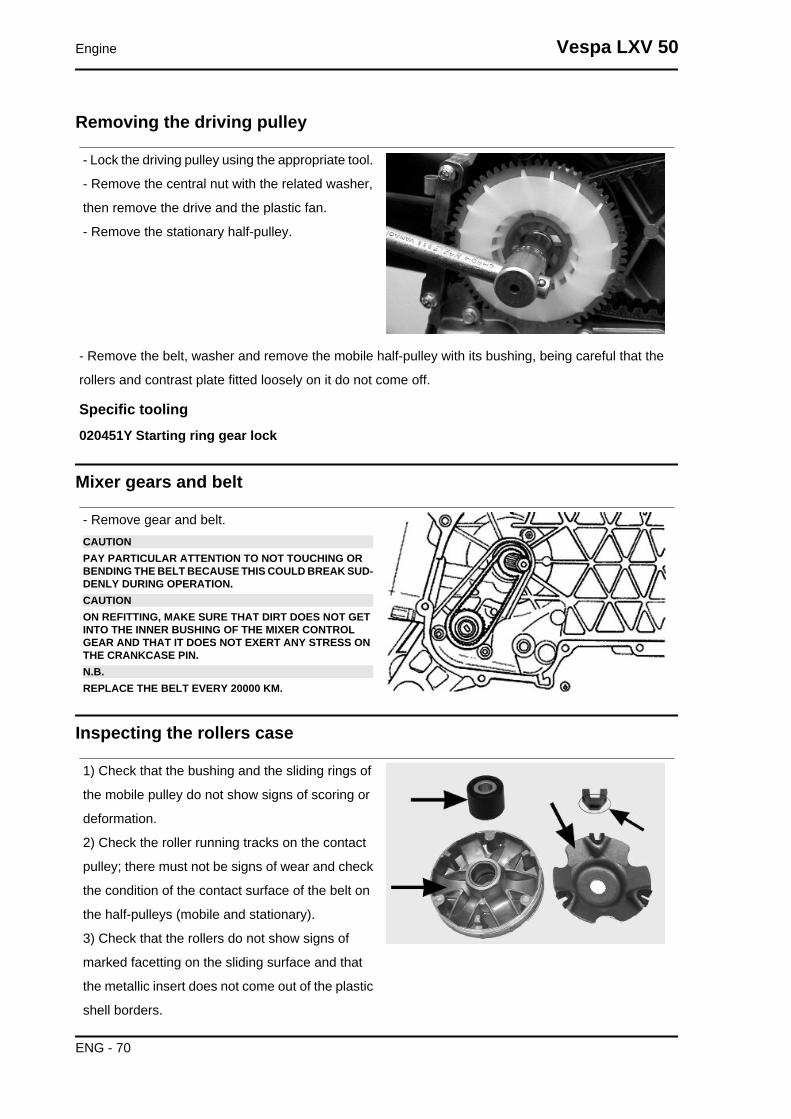
Removing the driving pulley
- Lock the driving pulley using the appropriate tool.
- Remove the central nut with the related washer,
then remove the drive and the plastic fan.
- Remove the stationary half-pulley.
- Remove the belt, washer and remove the mobile half-pulley with its bushing, being careful that the
rollers and contrast plate fitted loosely on it do not come off.
Specific tooling020451Y Starting ring gear lock
Mixer gears and belt
- Remove gear and belt.CAUTIONPAY PARTICULAR ATTENTION TO NOT TOUCHING ORBENDING THE BELT BECAUSE THIS COULD BREAK SUD-DENLY DURING OPERATION.CAUTIONON REFITTING, MAKE SURE THAT DIRT DOES NOT GETINTO THE INNER BUSHING OF THE MIXER CONTROLGEAR AND THAT IT DOES NOT EXERT ANY STRESS ONTHE CRANKCASE PIN.N.B.REPLACE THE BELT EVERY 20000 KM.
Inspecting the rollers case
1) Check that the bushing and the sliding rings of
the mobile pulley do not show signs of scoring or
deformation.
2) Check the roller running tracks on the contact
pulley; there must not be signs of wear and check
the condition of the contact surface of the belt on
the half-pulleys (mobile and stationary).
3) Check that the rollers do not show signs of
marked facetting on the sliding surface and that
the metallic insert does not come out of the plastic
shell borders.
Engine Vespa LXV 50
ENG - 70
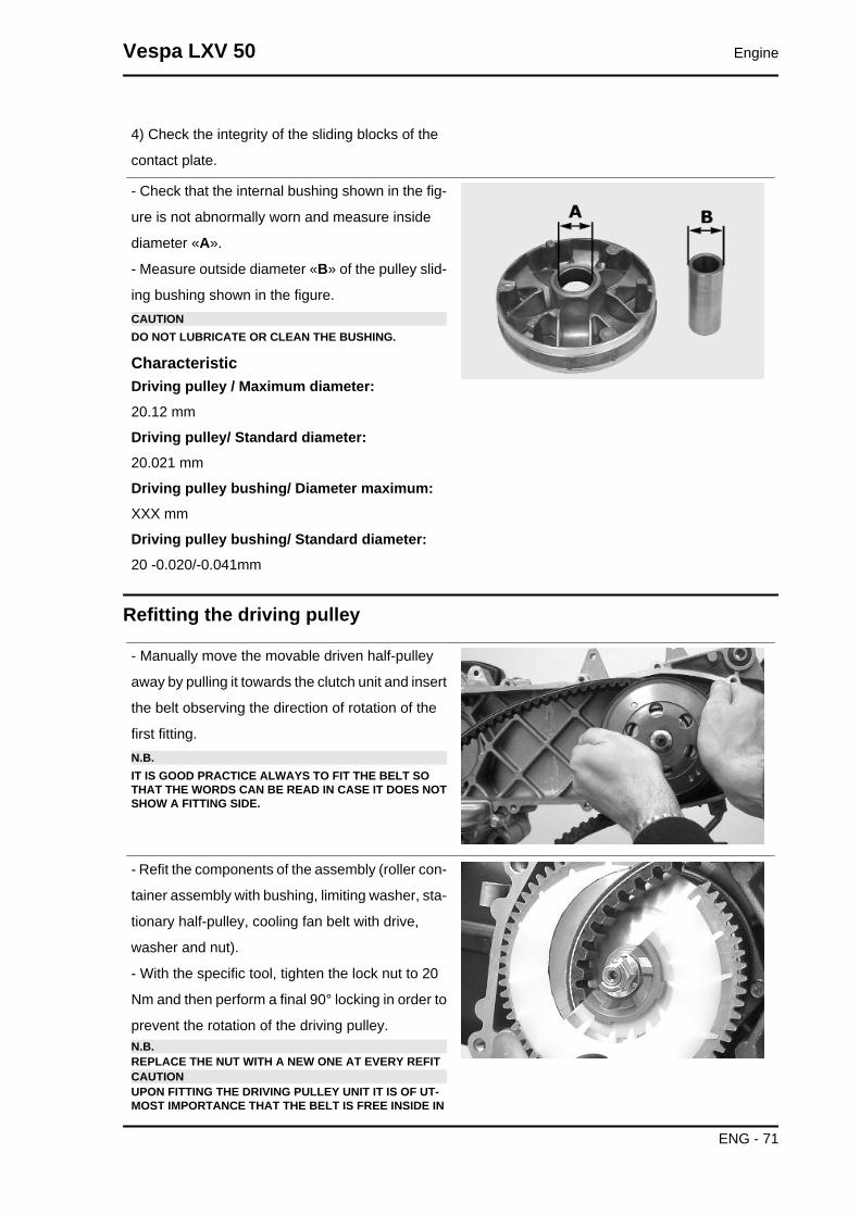
4) Check the integrity of the sliding blocks of the
contact plate.
- Check that the internal bushing shown in the fig-
ure is not abnormally worn and measure inside
diameter «A».
- Measure outside diameter «B» of the pulley slid-
ing bushing shown in the figure.CAUTIONDO NOT LUBRICATE OR CLEAN THE BUSHING.
CharacteristicDriving pulley / Maximum diameter:20.12 mm
Driving pulley/ Standard diameter:20.021 mm
Driving pulley bushing/ Diameter maximum:XXX mm
Driving pulley bushing/ Standard diameter:20 -0.020/-0.041mm
Refitting the driving pulley
- Manually move the movable driven half-pulley
away by pulling it towards the clutch unit and insert
the belt observing the direction of rotation of the
first fitting.N.B.IT IS GOOD PRACTICE ALWAYS TO FIT THE BELT SOTHAT THE WORDS CAN BE READ IN CASE IT DOES NOTSHOW A FITTING SIDE.
- Refit the components of the assembly (roller con-
tainer assembly with bushing, limiting washer, sta-
tionary half-pulley, cooling fan belt with drive,
washer and nut).
- With the specific tool, tighten the lock nut to 20
Nm and then perform a final 90° locking in order to
prevent the rotation of the driving pulley.N.B.REPLACE THE NUT WITH A NEW ONE AT EVERY REFITCAUTIONUPON FITTING THE DRIVING PULLEY UNIT IT IS OF UT-MOST IMPORTANCE THAT THE BELT IS FREE INSIDE IN
Vespa LXV 50 Engine
ENG - 71

ORDER TO AVOID WRONG TIGHTENING AND CONSE-QUENTLY DAMAGING THE CRANKSHAFT KNURLING.
Specific tooling020451Y Starting ring gear lock
Locking torques (N*m)Crankshaft pulley nut 18 to 20 + 90° Nm
For 25 km/h engine type versions, the limit washer is 5.5 mm thick
End gear
Removing the hub cover
• Remove the transmission cover
• Remove the clutch assembly
• Discharge the rear hub oil.
• Remove the 5 screws indicated in the figure.
• Remove the hub cover with driven pulley shaft.
See alsoRefitting the clutch
Removing the wheel axle
- Remove the intermediate gear and the complete
gear wheel axle.
- When removing the intermediate gear pay atten-
tion to the various shim adjustments.
Engine Vespa LXV 50
ENG - 72

Removing the wheel axle bearings
- Remove the oil seal and the seeger ring.
- Remove the bearing by pushing from the outside
towards the inside of the gear compartment, using
the appropriate punch.
Specific tooling020363Y 20 mm guide
020376Y Adaptor handle
020358Y 37x40-mm adaptor
Removing the driven pulley shaft bearing
- Remove the seeger ring inside the cover.
- Remove the oil seal from the outside.
- Remove the centring dowels and position the
cover on a plane.
- Position the special tool on the internal track of
the bearing and remove said bearing with the aid
of a press.
Specific tooling020452Y Tube for removing and refitting thedriven pulley shaft
- Position the special tube on the internal raceway
of the bearing and from the shaft toothed side as
indicated in the figure. Expel the driven pulley shaft
with the aid of a press.
Specific tooling020452Y Tube for removing and refitting thedriven pulley shaft
Vespa LXV 50 Engine
ENG - 73
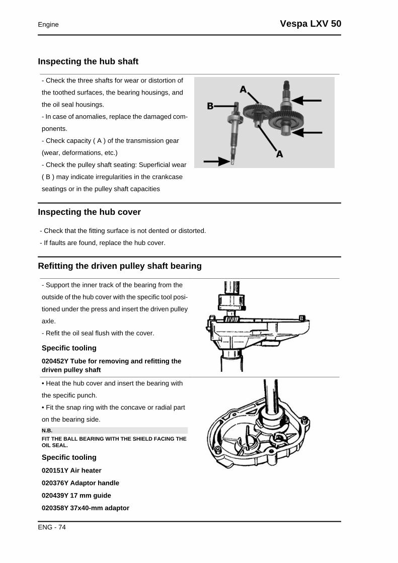
Inspecting the hub shaft
- Check the three shafts for wear or distortion of
the toothed surfaces, the bearing housings, and
the oil seal housings.
- In case of anomalies, replace the damaged com-
ponents.
- Check capacity ( A ) of the transmission gear
(wear, deformations, etc.)
- Check the pulley shaft seating: Superficial wear
( B ) may indicate irregularities in the crankcase
seatings or in the pulley shaft capacities
Inspecting the hub cover
- Check that the fitting surface is not dented or distorted.
- If faults are found, replace the hub cover.
Refitting the driven pulley shaft bearing
- Support the inner track of the bearing from the
outside of the hub cover with the specific tool posi-
tioned under the press and insert the driven pulley
axle.
- Refit the oil seal flush with the cover.
Specific tooling020452Y Tube for removing and refitting thedriven pulley shaft
• Heat the hub cover and insert the bearing with
the specific punch.
• Fit the snap ring with the concave or radial part
on the bearing side.N.B.FIT THE BALL BEARING WITH THE SHIELD FACING THEOIL SEAL.
Specific tooling020151Y Air heater
020376Y Adaptor handle
020439Y 17 mm guide
020358Y 37x40-mm adaptor
Engine Vespa LXV 50
ENG - 74

Refitting the wheel axle bearing
- Heat the half crankcase on the transmission side
using a thermal gun.
- After lubricating its outer strip, insert the bearing
with the special adapter with the aid of a hammer.
- Refit the seeger ring and the oil seal using the 42
x 47 mm adapter and the handle.
Specific tooling020151Y Air heater
020376Y Adaptor handle
020363Y 20 mm guide
020359Y 42x47-mm adaptor
Refitting the ub cover
- Refit the whole wheel axle.
- Refit the intermediate gear paying attention to the
two shim thicknesses.
- Apply LOCTITE 510 for surfaces to the hub cov-
ers and refit the same with driven pulley shaft.
- Refit the 5 screws and tighten them to the speci-
fied torque.N.B.CLEAN THE CONTACT SURFACES OF THE HUB COVERAND THE HALF CRANKCASE OF RESIDUE FROM PREVI-OUS GASKETS BEFORE APPLYING A NEW ONE.
Locking torques (N*m)Locking torque: 11 to 13 Nm
Flywheel cover
Vespa LXV 50 Engine
ENG - 75

Cooling hood
- Remove the four fixings shown in the figure.
- Remove the fan cover
- Remove the oil piping retention band from the
hood
- Remove the 2 screws shown in the figure
Cooling fan
- Remove the cooling fan by acting on the three
fixings indicated in the figure.
Engine Vespa LXV 50
ENG - 76
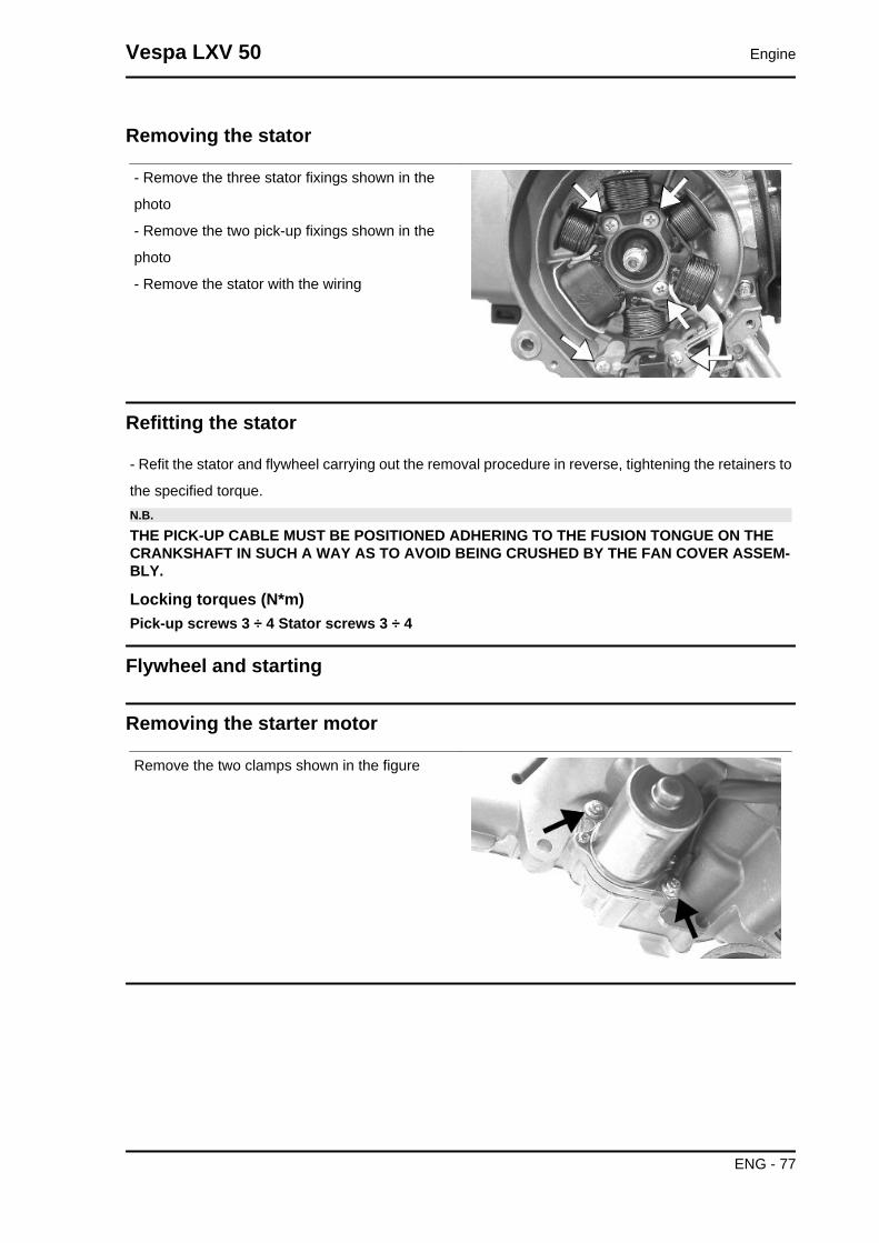
Removing the stator
- Remove the three stator fixings shown in the
photo
- Remove the two pick-up fixings shown in the
photo
- Remove the stator with the wiring
Refitting the stator
- Refit the stator and flywheel carrying out the removal procedure in reverse, tightening the retainers to
the specified torque.N.B.
THE PICK-UP CABLE MUST BE POSITIONED ADHERING TO THE FUSION TONGUE ON THECRANKSHAFT IN SUCH A WAY AS TO AVOID BEING CRUSHED BY THE FAN COVER ASSEM-BLY.
Locking torques (N*m)Pick-up screws 3 ÷ 4 Stator screws 3 ÷ 4
Flywheel and starting
Removing the starter motor
Remove the two clamps shown in the figure
Vespa LXV 50 Engine
ENG - 77

Removing the flywheel magneto
- Lock the rotation of the flywheel using the calliper
spanner.
- Remove the nut.CAUTIONTHE USE OF A CALLIPER SPANNER OTHER THAN THEONE SUPPLIED COULD DAMAGE THE STATOR COILS
- Extract the flywheel with the extractor.
Specific tooling020565Y Flywheel lock calliper spanner
020162Y Flywheel extractor
Inspecting the flywheel components
- Check the condition of the flywheel and any dis-
tortions that might cause rubbing on the stator and
on the Pick-Up.
Refitting the flywheel magneto
- Fit the flywheel being careful to insert the key
properly.
- Lock the flywheel nut at the prescribed torque
- Check the Pick-Up air gap.
- The air gap may not be modified in the fitting of
the Pick-Up.
- Other values derive from deformations visible on
the Pick-Up support.
Engine Vespa LXV 50
ENG - 78
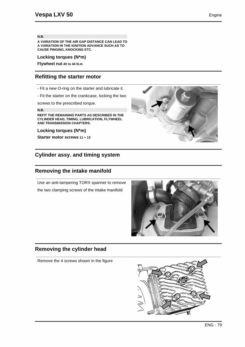
N.B.A VARIATION OF THE AIR GAP DISTANCE CAN LEAD TOA VARIATION IN THE IGNITION ADVANCE SUCH AS TOCAUSE PINGING, KNOCKING ETC.
Locking torques (N*m)Flywheel nut 40 to 44 N.m
Refitting the starter motor
- Fit a new O-ring on the starter and lubricate it.
- Fit the starter on the crankcase, locking the two
screws to the prescribed torque.N.B.REFIT THE REMAINING PARTS AS DESCRIBED IN THECYLINDER HEAD, TIMING, LUBRICATION, FLYWHEELAND TRANSMISSION CHAPTERS.
Locking torques (N*m)Starter motor screws 11 ÷ 13
Cylinder assy. and timing system
Removing the intake manifold
Use an anti-tampering TORX spanner to remove
the two clamping screws of the intake manifold
Removing the cylinder head
Remove the 4 screws shown in the figure
Vespa LXV 50 Engine
ENG - 79

Removing the cylinder - piston assy.
Remove the cylinder very carefully
Remove the snap rings and remove the pinCAUTIONAFTER EACH REMOVAL OPERATION REPLACE THE PINRETENTION SNAP RINGS
Inspecting the small end
- Measure the internal diameter of the small end
using an internal micrometer.N.B.IF THE DIAMETER OF THE ROD SMALL END EXCEEDSTHE MAXIMUM DIAMETER ALLOWED, SHOWS SIGNS OFWEAR OR OVERHEATING REPLACE THE CRANKSHAFTAS DESCRIBED IN THE "CRANKCASE AND CRANK-SHAFT" CHAPTER".
CharacteristicRod small end: standard diameter17 +0.011-0.001
Rod small end: maximum allowable diameter17,060 mm
Engine Vespa LXV 50
ENG - 80
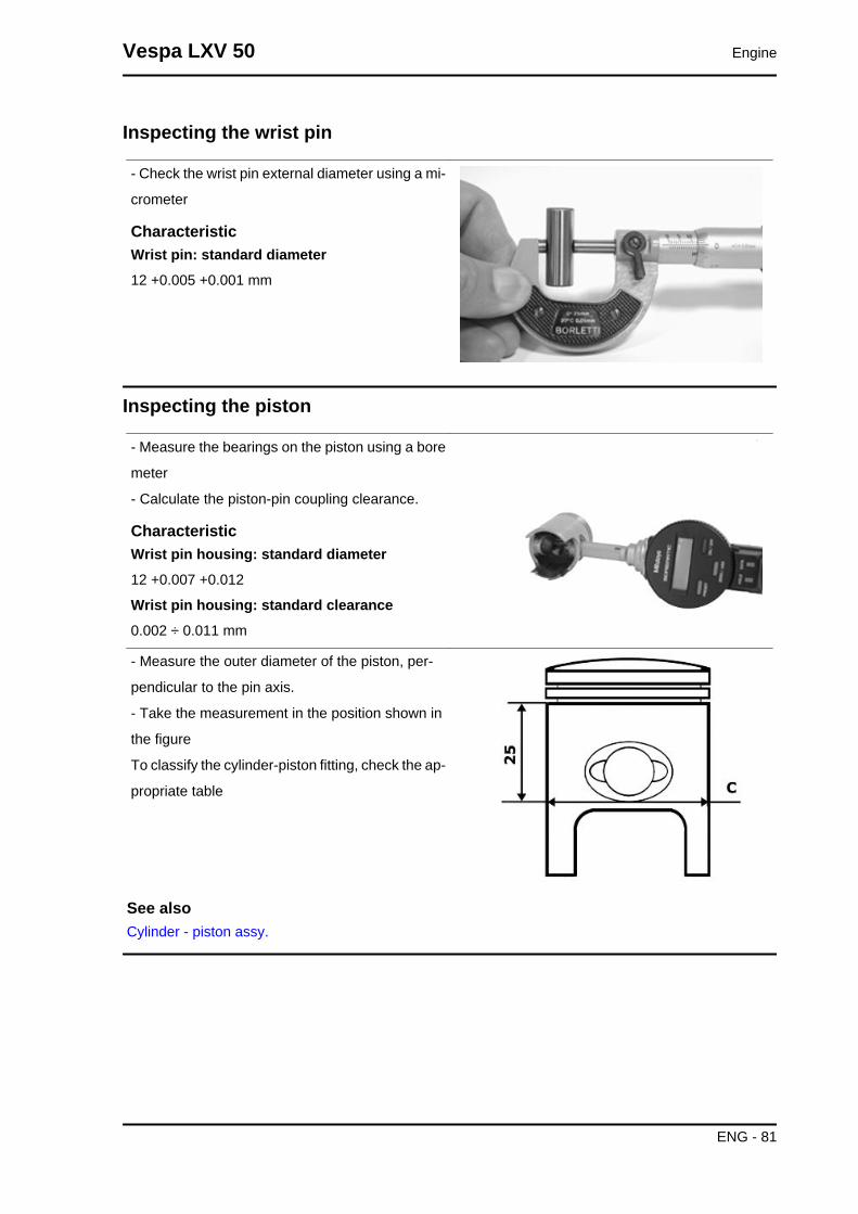
Inspecting the wrist pin
- Check the wrist pin external diameter using a mi-
crometer
CharacteristicWrist pin: standard diameter12 +0.005 +0.001 mm
Inspecting the piston
- Measure the bearings on the piston using a bore
meter
- Calculate the piston-pin coupling clearance.
CharacteristicWrist pin housing: standard diameter12 +0.007 +0.012
Wrist pin housing: standard clearance0.002 ÷ 0.011 mm
- Measure the outer diameter of the piston, per-
pendicular to the pin axis.
- Take the measurement in the position shown in
the figure
To classify the cylinder-piston fitting, check the ap-
propriate table
See alsoCylinder - piston assy.
Vespa LXV 50 Engine
ENG - 81

Inspecting the cylinder
- Check that the cylinder does not show seizures.
Otherwise, replace it or adjust it respecting the al-
lowable increases
- Measure the internal diameter of the cylinder with
a bore meter, according to the directions given in
the figure
- Check that the fitting surface with the head is not
dented or distorted.
To classify the cylinder-piston fitting, check the ap-
propriate table
See alsoCylinder - piston assy.
Inspecting the piston rings
- Alternatively insert the two sealing rings in the
cylinder
Using the piston, insert the seals perpendicularly
to the cylinder axis.
- Measure the opening of the sealing rings using a
thickness gauge as shown in the photograph
- If the values are higher than the values prescri-
bed in the chart, substitute the rings
Removing the piston
- Position the snap ring in detail 1 with the opening straddling the arrow printed on the tool.
-Push detail 2 into detail 1 until the stop and extract detail 2.
- Insert detail 3 into detail 1, position the assembly in the snap ring assembly area, and push detail 3
all the way in.N.B.
REFIT THE REMAINING PARTS FOLLOWING THE OPERATIONS IN REVERSE ORDER FROMTHE REMOVAL OPERATIONS
Specific tooling020166Y Pin lock fitting tool
Locking torques (N*m)Locking head nuts: 10 to 11 N·m
Engine Vespa LXV 50
ENG - 82

- Use new wrist pin snap rings.
- Use new cylinder base gasket.
- Before refitting carefully clean all the surfaces.
- Use oil to be mixed during the fitting of the piston
and the cylinder.CAUTIONPOSITION THE ARROW PRINTED ON THE PISTONCROWN TOWARDS THE EXHAUST OPENING.THE WRIST PIN SNAP RINGS MUST BE POSITIONED ONTHE PISTON WITH THE SPECIFIC TOOL
Recommended productsAGIP CITY TEC 2T OilRecommended oil
Vespa LXV 50 Engine
ENG - 83
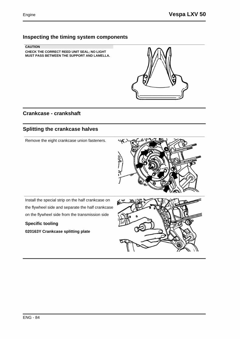
Inspecting the timing system componentsCAUTIONCHECK THE CORRECT REED UNIT SEAL; NO LIGHTMUST PASS BETWEEN THE SUPPORT AND LAMELLA.
Crankcase - crankshaft
Splitting the crankcase halves
Remove the eight crankcase union fasteners.
Install the special strip on the half crankcase on
the flywheel side and separate the half crankcase
on the flywheel side from the transmission side
Specific tooling020163Y Crankcase splitting plate
Engine Vespa LXV 50
ENG - 84

Removing the crankshaft
- Install the specific tool on the half crankcase on
the transmission side using four M6 screws of an
adequate length.
- Remove the crankshaft from the transmission
side half crankcase
Specific tooling020163Y Crankcase splitting plate
Removing the crankshaft bearings
The bearings can stay on either the half crankcase
or the crankshaft indifferently
- Using the special tool, remove any bearings that
have been left on the crankshaftN.B.The half rings must be inserted on the bearings with a few mal-let blows.
Specific tooling004499Y001 Bearing extractor bell
004499Y006 Bearing extractor ring
004499Y002 Bearing extractor screw
004499Y007 Half rings
- Using the specific tool remove any bearings left
on the half crankcase
Specific tooling001467Y007 Driver for OD 54 mm bearing
001467Y006 Pliers to extract 20 mm bearings
Vespa LXV 50 Engine
ENG - 85
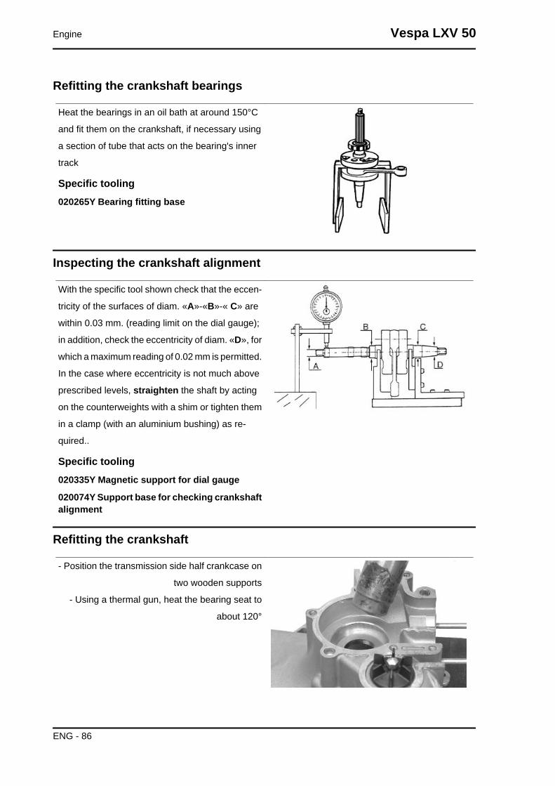
Refitting the crankshaft bearings
Heat the bearings in an oil bath at around 150°C
and fit them on the crankshaft, if necessary using
a section of tube that acts on the bearing's inner
track
Specific tooling020265Y Bearing fitting base
Inspecting the crankshaft alignment
With the specific tool shown check that the eccen-
tricity of the surfaces of diam. «A»-«B»-« C» are
within 0.03 mm. (reading limit on the dial gauge);
in addition, check the eccentricity of diam. «D», for
which a maximum reading of 0.02 mm is permitted.
In the case where eccentricity is not much above
prescribed levels, straighten the shaft by acting
on the counterweights with a shim or tighten them
in a clamp (with an aluminium bushing) as re-
quired..
Specific tooling020335Y Magnetic support for dial gauge
020074Y Support base for checking crankshaftalignment
Refitting the crankshaft
- Position the transmission side half crankcase on
two wooden supports
- Using a thermal gun, heat the bearing seat to
about 120°
Engine Vespa LXV 50
ENG - 86

- Firmly insert the crankshaft until the bearing rea-
ches the end-of-stroke stop
- Let the temperature of the half crankcase settle
at the temperature of the crankshaft.
- Again install the special crankcase separation
plate NOT installing the crankshaft protection
- During the assembly phase keep the central
thrust screw loose.
- Take the four clamping screws to the end of the
stroke and loosen them again with the same angle
(e.g. 90°)
- When the temperature has settled, preload the
thrust screw of the tool manually until the ball bear-
ing clearance is cancelled out.
Specific tooling020163Y Crankcase splitting plate
Refitting the crankcase halves
- Prepare the coupling surface with LOCTITE 510
applying a thin layer of it after degreasing the sur-
face using a suitable solvent (e.g. trichloroethy-
lene)
- Heat the flywheel-side half crankcase with a ther-
mal gun.
Recommended productsLoctite 510 Liquid sealantGasket
Vespa LXV 50 Engine
ENG - 87

- Keeping the half crankcase on the transmission
side, insert the flywheel side half crankcase with a
clean precise movement
- Insert at least three clamping screws and tighten
up rapidly
- Insert the other 5 screws and tighten them to the
specified torque.
Locking torques (N*m)crankcase coupling screws 11 - 13
- Move the crankcase separation plate in a position
back from the one indicated in the figure
- Install the special magnetic support with dial
gauge at the end of the crankshaft
- Check the axial clearance of the crankcase
If this is not within the maximum limit allowed, re-
peat the crankcase coupling procedure
Specific tooling020335Y Magnetic support for dial gauge
CharacteristicAxial clearance with warm crankcase0.10 ÷ 0.12 mm
Axial clearance with cold crankcase0.06 to 0.08 mm
Limit value with cold crankcase0.02 ÷ 0.03 mm
Lubrication
Crankshaft oil seals
Engine Vespa LXV 50
ENG - 88

Refitting
- Install a new flywheel-side oil seal only with the
special tool's punch
The flywheel-side oil seal is recognised by its
smaller diameterN.B.THE USE OF THE SPECIFIC TOOL IS NOT COMPATIBLEWITH THE FITTED WRENCH
Specific tooling020340Y Flywheel and transmission oil sealsfitting punch
- Install a new transmission side oil seal using the
special tool with adapter ring.
The transmission-side oil seal is recognised by the
larger diameter
Specific tooling020340Y Flywheel and transmission oil sealsfitting punch
Oil pump
Removal
- Remove the 2 screws shown in the figure
Vespa LXV 50 Engine
ENG - 89
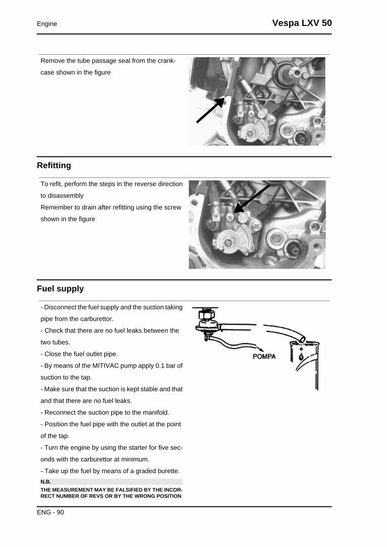
Remove the tube passage seal from the crank-
case shown in the figure
Refitting
To refit, perform the steps in the reverse direction
to disassembly
Remember to drain after refitting using the screw
shown in the figure
Fuel supply
- Disconnect the fuel supply and the suction taking
pipe from the carburettor.
- Check that there are no fuel leaks between the
two tubes.
- Close the fuel outlet pipe.
- By means of the MITIVAC pump apply 0.1 bar of
suction to the tap.
- Make sure that the suction is kept stable and that
and that there are no fuel leaks.
- Reconnect the suction pipe to the manifold.
- Position the fuel pipe with the outlet at the point
of the tap.
- Turn the engine by using the starter for five sec-
onds with the carburettor at minimum.
- Take up the fuel by means of a graded burette.N.B.THE MEASUREMENT MAY BE FALSIFIED BY THE INCOR-RECT NUMBER OF REVS OR BY THE WRONG POSITION
Engine Vespa LXV 50
ENG - 90
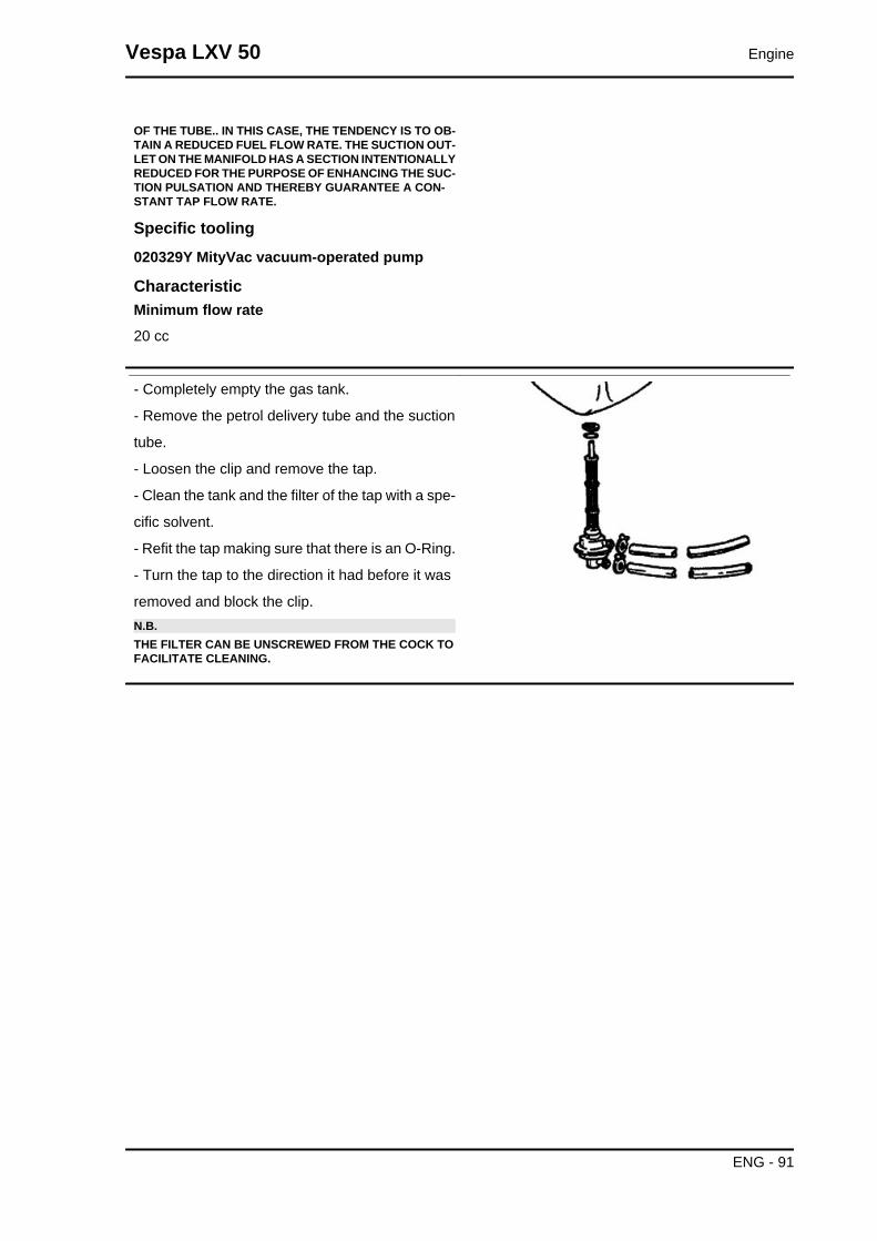
OF THE TUBE.. IN THIS CASE, THE TENDENCY IS TO OB-TAIN A REDUCED FUEL FLOW RATE. THE SUCTION OUT-LET ON THE MANIFOLD HAS A SECTION INTENTIONALLYREDUCED FOR THE PURPOSE OF ENHANCING THE SUC-TION PULSATION AND THEREBY GUARANTEE A CON-STANT TAP FLOW RATE.
Specific tooling020329Y MityVac vacuum-operated pump
CharacteristicMinimum flow rate20 cc
- Completely empty the gas tank.
- Remove the petrol delivery tube and the suction
tube.
- Loosen the clip and remove the tap.
- Clean the tank and the filter of the tap with a spe-
cific solvent.
- Refit the tap making sure that there is an O-Ring.
- Turn the tap to the direction it had before it was
removed and block the clip.N.B.THE FILTER CAN BE UNSCREWED FROM THE COCK TOFACILITATE CLEANING.
Vespa LXV 50 Engine
ENG - 91

INDEX OF TOPICS
SUSPENSIONS SUSP

This section is devoted to operations that can be carried out on the suspension.
Front
Removing the front wheel
- Remove the five Allen screws that fix the wheel
to the hub.N.B.BEFORE REMOVING THE WHEEL HUB, REMOVE THEBRAKE CALLIPER.
Front wheel hub overhaul
- Remove the ball bearing check seeger ring indi-
cated in the photograph
Extract the ball bearing using the specific tool
Specific tooling001467Y014 Pliers to extract ø 15-mm bearings
001467Y017 Bell for bearings, OD 39 mm
Vespa LXV 50 Suspensions
SUSP - 93

- Remove the oil seal on the roller bearing side
using a screwdriver.
- Remove the roller bearing using the specific tool
Specific tooling020376Y Adaptor handle
020456Y Ø 24 mm adaptor
020363Y 20 mm guide
- Heat the roller bearing seat with a heat gun
- Use the specific tool to introduce and push the
bearing until it stops, with the shielded side facing
out
- Refit the ball bearing check seeger ring
Specific tooling020151Y Air heater
020376Y Adaptor handle
020359Y 42x47-mm adaptor
020412Y 15 mm guide
- Use the specific tool to fit and push the roller cas-
ing until it stops
- Refit the oil seal on the roller bearing side
- Lubricate the area between the roller bearing and
the ball bearing
Specific tooling020038Y Punch
Recommended productsAGIP GREASE MU3 Grease for odometertransmission gear case
Suspensions Vespa LXV 50
SUSP - 94
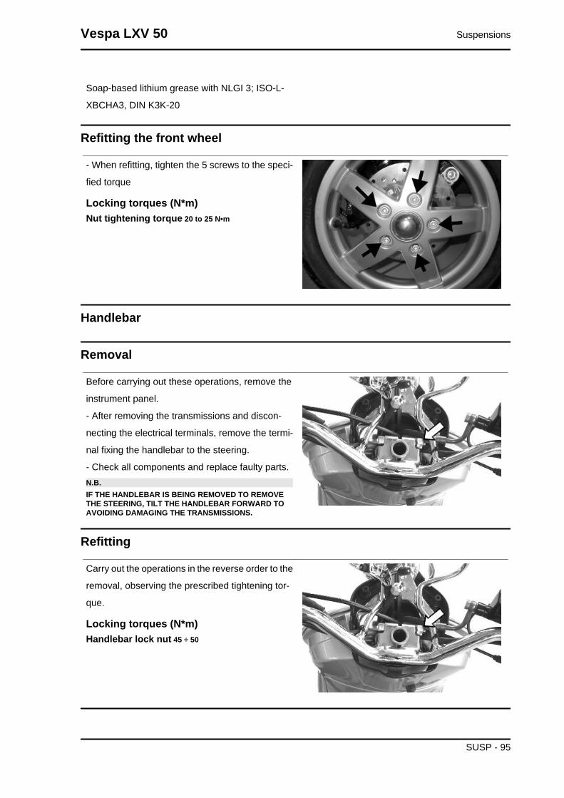
Soap-based lithium grease with NLGI 3; ISO-L-
XBCHA3, DIN K3K-20
Refitting the front wheel
- When refitting, tighten the 5 screws to the speci-
fied torque
Locking torques (N*m)Nut tightening torque 20 to 25 N•m
Handlebar
Removal
Before carrying out these operations, remove the
instrument panel.
- After removing the transmissions and discon-
necting the electrical terminals, remove the termi-
nal fixing the handlebar to the steering.
- Check all components and replace faulty parts.N.B.IF THE HANDLEBAR IS BEING REMOVED TO REMOVETHE STEERING, TILT THE HANDLEBAR FORWARD TOAVOIDING DAMAGING THE TRANSMISSIONS.
Refitting
Carry out the operations in the reverse order to the
removal, observing the prescribed tightening tor-
que.
Locking torques (N*m)Handlebar lock nut 45 ÷ 50
Vespa LXV 50 Suspensions
SUSP - 95

Steering column
Removal
After removing the upper seat, lean the vehicle on
one side and extract the steering tube completely
from the fork.
Specific tooling020055Y Wrench for steering tube ring nut
Overhaul
Use the tool fitted with parts 3 and 4, as indicated
to fit the pin, and press operating the handgrip,
until wedging the washers on the swinging hub.
- Remove the spacers, part 17, fill with grease the
area between the steering tube and the swinging
hub, and place the dust guard rings in that place.
* Supplied with the toolN.B.ASSEMBLE THE LOWER HOUSING ON HE STEERINGTUBE WITH A TUBE SECTION OF AN ADEQUATE DIAME-TER.
Specific tooling020021Y Front suspension service tool
001330Y Tool for fitting steering seats
Recommended productsAGIP GREASE PV2 Grease for control leverson the engineWhite anhydrous-calcium based grease to protect
roller bearings; temperature range between -20 °
C and +120 °C; NLGI 2; ISO-L-XBCIB2
Suspensions Vespa LXV 50
SUSP - 96

- Lubricate the sealing rings with mineral oil and
half-fill the roller casings with grease.
- Insert the seal ring on the pin and the roller bush-
ing with wedging washers at the same time.
- Remove the specific tool, then the part 5 (guiding)
partially ejected in the previous assembly stage;
leave part 4* always fitted.
- Replace part 3 with part 16* on the stem.
- Push, from the handgrip, the wedging washer -
roller casing - seal ring unit, placing part 16 until it
stops on the swinging hub
- Repeat the operation described above using the
tool fitted with part 16 and part 22* instead of part
4 on the stem, on the side opposite the one shown
in the figure to refit the second wedging washer -
roller casing - sealing ring unit.
* Supplied with the tool
Specific tooling020021Y Front suspension service tool
Recommended productsAGIP GREASE PV2 Grease for control leverson the engineWhite anhydrous-calcium based grease to protect
roller bearings; temperature range between -20 °
C and +120 °C; NLGI 2; ISO-L-XBCIB2
- Fit both dust guard rings «C» on the swinging hub
as shown in the detail drawing «A».
- Connect the swinging hub to the steering tube
with the guide pin, part 5*.
- Use the specific tool fitted with part 3* on its stem
and with part 4 at the bottom of the tool.
- Insert the previously greased pin on the swinging
hub and with the tool handgrip, move part 3 until it
stops on the steering tube.
- After fitting the pin, insert the two spacers, part
17*, slightly hitting with the mallet.
Vespa LXV 50 Suspensions
SUSP - 97
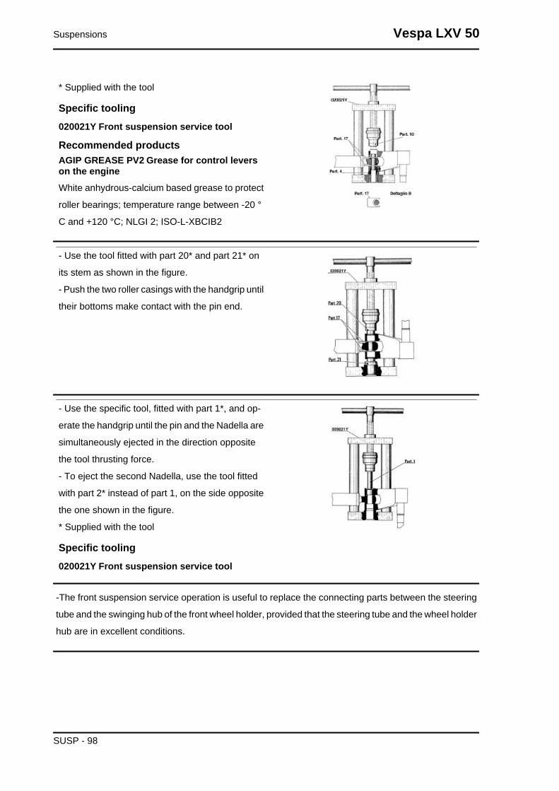
* Supplied with the tool
Specific tooling020021Y Front suspension service tool
Recommended productsAGIP GREASE PV2 Grease for control leverson the engineWhite anhydrous-calcium based grease to protect
roller bearings; temperature range between -20 °
C and +120 °C; NLGI 2; ISO-L-XBCIB2
- Use the tool fitted with part 20* and part 21* on
its stem as shown in the figure.
- Push the two roller casings with the handgrip until
their bottoms make contact with the pin end.
- Use the specific tool, fitted with part 1*, and op-
erate the handgrip until the pin and the Nadella are
simultaneously ejected in the direction opposite
the tool thrusting force.
- To eject the second Nadella, use the tool fitted
with part 2* instead of part 1, on the side opposite
the one shown in the figure.
* Supplied with the tool
Specific tooling020021Y Front suspension service tool
-The front suspension service operation is useful to replace the connecting parts between the steering
tube and the swinging hub of the front wheel holder, provided that the steering tube and the wheel holder
hub are in excellent conditions.
Suspensions Vespa LXV 50
SUSP - 98
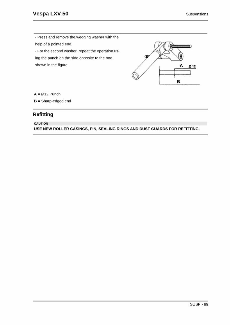
- Press and remove the wedging washer with the
help of a pointed end.
- For the second washer, repeat the operation us-
ing the punch on the side opposite to the one
shown in the figure.
A = Ø12 Punch
B = Sharp-edged end
RefittingCAUTION
USE NEW ROLLER CASINGS, PIN, SEALING RINGS AND DUST GUARDS FOR REFITTING.
Vespa LXV 50 Suspensions
SUSP - 99

When fitting the fork, lubricate with the steering
bearing tracks with the recommended grease.
Tighten the lower ring nut "A" and the upper ring
nut "B" to the specified torque
Recommended productsAGIP GREASE PV2 Grease for the steeringbearings, pin seats and swinging armWhite anhydrous-calcium based grease to protect
roller bearings; temperature range between -20 C
and +120 C; NLGI 2; ISO-L-XBCIB2.
Locking torques (N*m)Steering lower ring nut 8 ÷ 10 Steering upperring nut 35 ÷ 40
Front shock absorber
Suspensions Vespa LXV 50
SUSP - 100
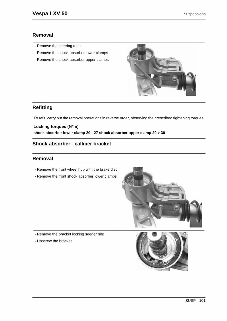
Removal
- Remove the steering tube
- Remove the shock absorber lower clamps
- Remove the shock absorber upper clamps
Refitting
To refit, carry out the removal operations in reverse order, observing the prescribed tightening torques.
Locking torques (N*m)shock absorber lower clamp 20 - 27 shock absorber upper clamp 20 ÷ 30
Shock-absorber - calliper bracket
Removal
- Remove the front wheel hub with the brake disc
- Remove the front shock absorber lower clamps
- Remove the bracket locking seeger ring
- Unscrew the bracket
Vespa LXV 50 Suspensions
SUSP - 101

- Before refitting the bracket in the wheel axle,
place the O-ring as shown in the photograph so
that it is correctly placed after fitting the bracket.
- Refit the washer and the Seeger ring.
- Refit the lower screws fixing the shock absorber
to the bracket and tighten at the prescribed torque
Locking torques (N*m)Lower shock absorber clamp 20 ÷ 27
Overhaul
- The bracket for the shock absorber -calliper at-
tachment has two roller bearings separated one
from the other as shown in the photograph
- Remove the two roller bearings from the bracket
with the specific tool operating on the shock ab-
sorber attachment side as shown in the photo-
graph
Specific tooling020376Y Adaptor handle
020441Y 26 x 28 mm adaptor
020365Y 22 mm guide
- Remove the oil seal on the wheel hub side with
the screwdriver as shown in the photograph
Suspensions Vespa LXV 50
SUSP - 102

- Suitably hold the brake calliper - shock absorber
attachment bracket
- Fit a new oil seal and move it until it stops using
the specific tool
Specific tooling020376Y Adaptor handle
020360Y Adaptor 52 x 55 mm
- Assemble a new roller bearing on the shock ab-
sorber side and move it until it stops using the
specific tool
Specific tooling020036Y Punch
- Suitably hold the brake calliper - shock absorber
attachment bracket
- Assemble a new roller bearing on the wheel hub
side and move it until it stops using the specific tool
Specific tooling020037Y Punch
Steering bearing
Removal
- Use the specific tool both to remove the lower seat of the upper bearing and to remove the upper seat
of the lower bearing fitted on the chassis.N.B.
TO REMOVE THE LOWER SEAT OF THE LOWER STEERING BEARING JUST USE A SCREW-DRIVER AS A LEVER BETWEEN THE SEATING AND THE SLEEVE.
Specific tooling020004Y Punch for removing fifth wheels from headstock
Vespa LXV 50 Suspensions
SUSP - 103
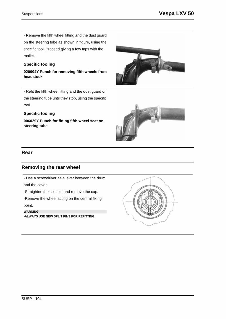
- Remove the fifth wheel fitting and the dust guard
on the steering tube as shown in figure, using the
specific tool. Proceed giving a few taps with the
mallet.
Specific tooling020004Y Punch for removing fifth wheels fromheadstock
- Refit the fifth wheel fitting and the dust guard on
the steering tube until they stop, using the specific
tool.
Specific tooling006029Y Punch for fitting fifth wheel seat onsteering tube
Rear
Removing the rear wheel
- Use a screwdriver as a lever between the drum
and the cover.
-Straighten the split pin and remove the cap.
-Remove the wheel acting on the central fixing
point.WARNING-ALWAYS USE NEW SPLIT PINS FOR REFITTING.
Suspensions Vespa LXV 50
SUSP - 104
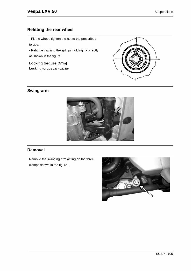
Refitting the rear wheel
- Fit the wheel, tighten the nut to the prescribed
torque.
- Refit the cap and the split pin folding it correctly
as shown in the figure.
Locking torques (N*m)Locking torque 137 ÷ 152 Nm
Swing-arm
Removal
Remove the swinging arm acting on the three
clamps shown in the figure.
Vespa LXV 50 Suspensions
SUSP - 105

Refitting
For rifting, respect the locking torques
Locking torques (N*m)Part C 33 ÷ 41 Part B 44 ÷ 52 Part A 33 ÷ 41
Shock absorbers
Suspensions Vespa LXV 50
SUSP - 106

Removal
- To replace the shock absorber remove the bat-
tery access flap to reach and remove the shock
absorber/ frame anchoring nut. Then remove the
shock absorber/engine anchorage nut.
- When refitting, tighten the shock absorber/chas-
sis anchoring nut and the shock absorber/engine
pin to the prescribed torque.
Locking torques (N*m)Shock absorber/engine pin torque 33 to 41 N·mShock absorber/frame nut torque 20 to 25 Nm
Vespa LXV 50 Suspensions
SUSP - 107
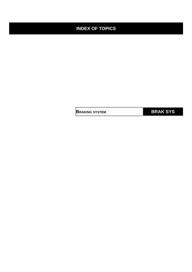
INDEX OF TOPICS
BRAKING SYSTEM BRAK SYS

1. Tank cover.
2 - Pump body.
3 - Brake lever.
4 - Pump plunger.
5- Oil delivery hose.
6 - Protection cap for air bleed screw.
7- Calliper.
8- Dust guard
9- Piston sealing ring.
10- Piston.
11 - Brake pad.
12 - Brake disc.
Front brake calliper
Removal
- Detach the oil brake hose from calliper, pouring
the fluid inside a container.
- Remove the mountings indicated in the figure.
- When refitting, tighten the nuts to the prescribed
torque.
- Bleed the system.
Locking torques (N*m)Calliper tightening screw 20 ÷ 25 Nm Brake fluidtube calliper 20 ÷ 25 Nm
Overhaul
- Remove the calliper assembling bolts and take out the internal bodies and components. If necessary,
in order to make it easier to take out the plungers, inject (shorts blasts of) compressed air through the
brake fluid pipe.
- Check that the cylinders of the internal and external body of the calliper do not show scratches or signs
of erosion; otherwise, replace the entire calliper.CAUTIONALL THE INTERNAL COMPONENTS MUST BE REPLACED EVERY TIME THE CALLIPER ISSERVICED.Fit to the calliper body:
- the sealing rings (1-2);
- the plungers (3);
Vespa LXV 50 Braking system
BRAK SYS - 109
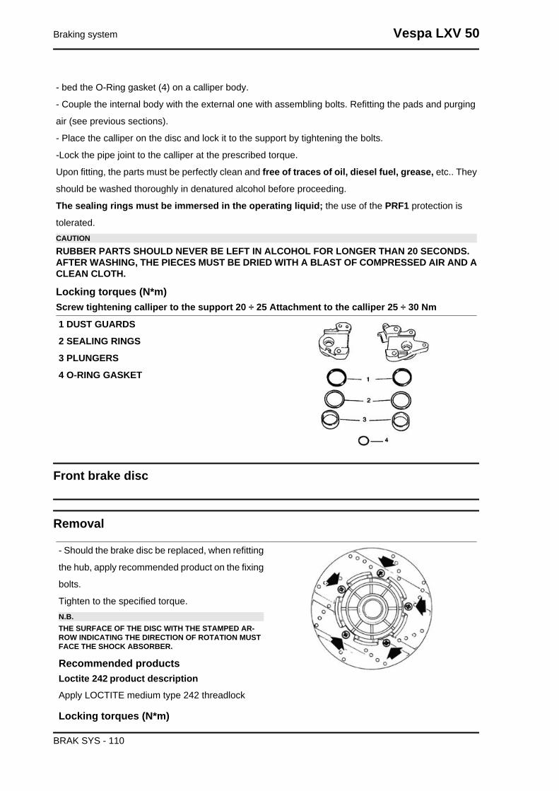
- bed the O-Ring gasket (4) on a calliper body.
- Couple the internal body with the external one with assembling bolts. Refitting the pads and purging
air (see previous sections).
- Place the calliper on the disc and lock it to the support by tightening the bolts.
-Lock the pipe joint to the calliper at the prescribed torque.
Upon fitting, the parts must be perfectly clean and free of traces of oil, diesel fuel, grease, etc.. They
should be washed thoroughly in denatured alcohol before proceeding.
The sealing rings must be immersed in the operating liquid; the use of the PRF1 protection is
tolerated.CAUTION
RUBBER PARTS SHOULD NEVER BE LEFT IN ALCOHOL FOR LONGER THAN 20 SECONDS.AFTER WASHING, THE PIECES MUST BE DRIED WITH A BLAST OF COMPRESSED AIR AND ACLEAN CLOTH.
Locking torques (N*m)Screw tightening calliper to the support 20 ÷ 25 Attachment to the calliper 25 ÷ 30 Nm
1 DUST GUARDS
2 SEALING RINGS
3 PLUNGERS
4 O-RING GASKET
Front brake disc
Removal
- Should the brake disc be replaced, when refitting
the hub, apply recommended product on the fixing
bolts.
Tighten to the specified torque.N.B.THE SURFACE OF THE DISC WITH THE STAMPED AR-ROW INDICATING THE DIRECTION OF ROTATION MUSTFACE THE SHOCK ABSORBER.
Recommended productsLoctite 242 product descriptionApply LOCTITE medium type 242 threadlock
Locking torques (N*m)
Braking system Vespa LXV 50
BRAK SYS - 110

tightening torque 5 ÷ 6.5 Nm
Disc Inspection
Specific tooling020335Y Magnetic support for dial gauge
CharacteristicMax oscillation allowed0.1 mm.
Front brake pads
Removal
- Pads must be replaced when the friction material
thickness reaches the wear limit.
- To replace:
remove the protection cover, the bolt and the leaf
spring. Slide off the pads and replace them once
the plungers are down. Carry out these operations
in reverse order to fit.CAUTIONBEFORE USING THE BRAKE, OPERATE THE LEVER AFEW TIMES.
Front
-Once the bleed valve is closed, fill the system with
brake liquid to the maximum level.
-Undo the bleed screw.
-Apply the tube of the special tool to the bleed
screws.
When bleeding it is necessary to fill the oil tank in
continuation while working with a MITYVAC pump
on the bleed screws until no more air comes out of
the system.
Vespa LXV 50 Braking system
BRAK SYS - 111

The operation is finished when just oil comes out
of the bleed screws.
-Do up the bleed screw.
-When the operation is over, tighten up the oil
bleed screw to the prescribed torque.N.B.IF AIR CONTINUES TO COME OUT DURING PURGING, EX-AMINE ALL THE FITTINGS:IF SAID FITTINGS DO NOT SHOW SIGNS OF BEING FAUL-TY, LOOK FOR THE AIR INPUT AMONG THE VARIOUSSEALS ON THE PUMP AND CALLIPER PISTONS.CAUTION- DURING THE OPERATIONS, THE VEHICLE MUST BE ONTHE STAND AND LEVEL.N.B.DURING PURGING FREQUENTLY CHECK THE LEVEL TOPREVENT AIR GETTING INTO THE SYSTEM THROUGHTHE PUMP.WARNING- BRAKING CIRCUIT FLUID IS HYGROSCOPIC. IT AB-SORBS HUMIDITY FROM THE SURROUNDING AIR.IF THE LEVEL OF HUMIDITY IN THE BRAKING FLUID EX-CEEDS A GIVEN VALUE, BRAKING EFFICIENCY WILL BEREDUCED.THEREFORE, ALWAYS USE FLUID FROM SEALED CON-TAINERS.UNDER NORMAL DRIVING AND CLIMATIC CONDITIONSYOU SHOULD CHANGE THIS LIQUID EVERY TWO YEARS.IF THE BRAKES ARE USED INTENSELY AND/OR INHARSH CONDITIONS, CHANGE THE FLUID MORE FRE-QUENTLY.CAUTIONWHEN CARRYING OUT THE OPERATION, BRAKE FLUIDMAY LEAK FROM BETWEEN THE BLEED SCREW AND ITSSEAT ON THE CALLIPER.CAREFULLY DRY THE CALLIPER AND DEGREASE THEDISC SHOULD THERE BE OIL ON IT.
Specific tooling020329Y MityVac vacuum-operated pump
Recommended productsAGIP BRAKE 4 Brake fluidFMVSS DOT 4 Synthetic fluid
Locking torques (N*m)Oil bleed screw 7 ÷ 10
Front brake pump
Braking system Vespa LXV 50
BRAK SYS - 112

Rear drum brake
Once the muffler and the wheel have been re-
moved, follow these steps:
1.Remove the shoe spring using the specific span-
ner.
2. Remove the shoe with the aid of a lever.
3. Refit the new shoes giving a few taps with the
mallet.
4. Attach the spring using the specific pliers.
Specific tooling020325Y Brake-shoe spring calliper
Vespa LXV 50 Braking system
BRAK SYS - 113

INDEX OF TOPICS
CHASSIS CHAS
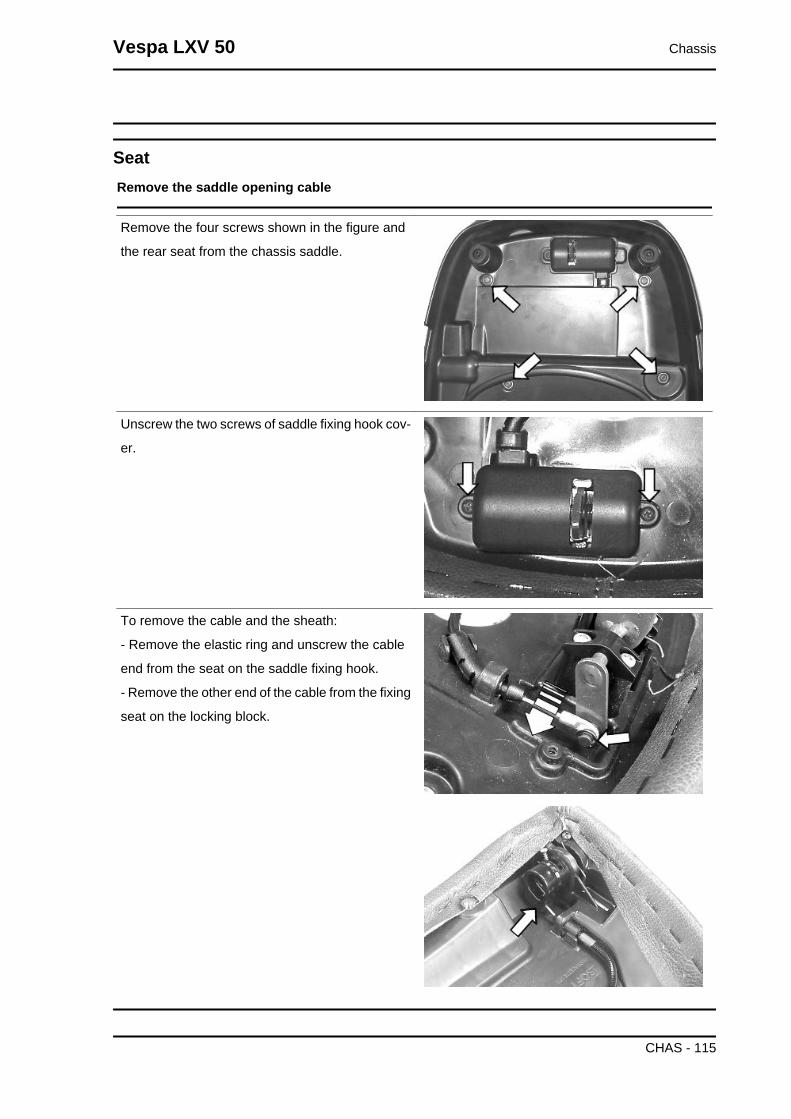
SeatRemove the saddle opening cable
Remove the four screws shown in the figure and
the rear seat from the chassis saddle.
Unscrew the two screws of saddle fixing hook cov-
er.
To remove the cable and the sheath:
- Remove the elastic ring and unscrew the cable
end from the seat on the saddle fixing hook.
- Remove the other end of the cable from the fixing
seat on the locking block.
Vespa LXV 50 Chassis
CHAS - 115

Instrument panel
- Remove the front grille
- Remove the shield back plate
- Remove the two fixing screws of the instrument
panel.
- Remove the odometer cable.
- Remove the connector of the electric connections
from the instrument panel
Instrument panel lower shell
- Remove the instrument panel
- Remove the handlebar
- Remove the two screws indicated in the figure.
- Remove the screw indicated in the figure, placed
under the handlebar light fitting
Chassis Vespa LXV 50
CHAS - 116

Headlight assy.
- Remove the four fixing screws from the light sup-
port.
Knee-guard
- Unscrew the 2 screws shown in the figure placed
under the front grille.
- Remove the 3 screws shown in the figure, placed
inside the glove-box; they can be reached after
opening the glove-box door.
Vespa LXV 50 Chassis
CHAS - 117

Footrest
- Operate on the 3 screws shown in the figure once
the glove-box and fairing have been removed.
Air filter
- Remove the helmet compartment.
- after removing the side fairing, remove the 2
screws fixing the filter box to the engine, indicated
in the figure.
- Remove the two clamps indicated in the figure
Chassis Vespa LXV 50
CHAS - 118
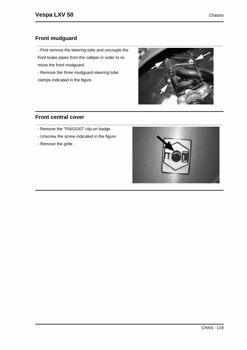
Front mudguard
- First remove the steering tube and uncouple the
front brake pipes from the calliper in order to re-
move the front mudguard
- Remove the three mudguard-steering tube
clamps indicated in the figure
Front central cover
- Remove the "PIAGGIO" clip-on badge
- Unscrew the screw indicated in the figure
- Remove the grille
Vespa LXV 50 Chassis
CHAS - 119

INDEX OF TOPICS
PRE-DELIVERY PRE DE
Aesthetic inspection
Appearance check:
- Paintwork
- Fitting of plastics
- Scratches
- Dirt
Tightening torques inspection
Lock check
- Safety locks
- clamping screws
Safety locks
Rear shock absorber upper fixing
Rear shock absorber lower fixing
Front wheel axle nut
Wheel hub nut
Frame - swinging arm bolt *
Swinging arm bolt - Engine
Engine arm pin - Frame arm
Handlebar lock nut
Steering lower ring nut
Upper steering ring nut
Electrical system
Electrical system:
- Main switch
- Headlamps: high-beam lights, low-beam lights, tail and parking lights and their warning lights
- Adjusting the headlights according to the regulations currently in force
- Rear light, parking light, stop light
- Front and rear stop light switches
- Turn indicators and their warning lights
- Instrument panel lights
- Instrument panel: fuel gauge
- Instrument panel warning lights
- Horn
- Starter
Vespa LXV 50 Pre-delivery
PRE DE - 121

CAUTION
TO ENSURE MAXIMUM PERFORMANCE, THE BATTERY MUST BE CHARGED BEFORE USE.INADEQUATE CHARGING OF THE BATTERY WITH A LOW LEVEL OF ELECTROLYTE BEFOREIT IS FIRST USED SHORTENS BATTERY LIFE.WARNING
BEFORE RECHARGING THE BATTERY, REMOVE THE CAPS OF EACH CELL.KEEP THE BATTERY AWAY FROM NAKED FLAMES OR SPARKS WHILE IT IS CHARGED.REMOVE THE BATTERY FROM THE SCOOTER, DISCONNECTING THE NEGATIVE TERMINALFIRST.CAUTION
WHEN INSTALLING THE BATTERY, ATTACH THE POSITIVE LEAD FIRST AND THEN THE NEG-ATIVE LEAD.WARNING
BATTERY ELECTROLYTE IS TOXIC AND IT MAY CAUSE SERIOUS BURNS. IT CONTAINS SUL-PHURIC ACID. AVOID CONTACT WITH EYES, SKIN AND CLOTHING.IN CASE OF CONTACT WITH EYES OR SKIN, RINSE WITH ABUNDANT WATER FOR ABOUT 15MINUTES AND SEEK MEDICAL ATTENTION AT ONCE.IF IT IS SWALLOWED, IMMEDIATELY DRINK LARGE QUANTITIES OF WATER OR VEGETABLEOIL. SEEK IMMEDIATE MEDICAL ATTENTION.BATTERIES PRODUCE EXPLOSIVE GAS; KEEP THEM AWAY FROM NAKED FLAMES, SPARKSAND CIGARETTES. IF THE BATTERY IS CHARGED IN A CLOSED PLACE, TAKE CARE TO EN-SURE ADEQUATE VENTILATION. ALWAYS PROTECT YOUR EYES WHEN WORKING CLOSE TOBATTERIES.KEEP OUT OF THE REACH OF CHILDRENCAUTION
NEVER USE FUSES WITH A CAPACITY HIGHER THAN THE RECOMMENDED CAPACITY. USINGA FUSE OF UNSUITABLE RATING MAY SERIOUSLY DAMAGE THE VEHICLE OR EVEN CAUSEA FIRE.
Levels check
Level check:
- Hydraulic braking system fluid level.
- Rear hub oil level
- Engine coolant level.
Road test
Test ride
- Cold start
- Instrument operations
- Response to the throttle control
- Stability on acceleration and braking
- Rear and front brake efficiency
- Rear and front suspension efficiency
- Abnormal noise
Pre-delivery Vespa LXV 50
PRE DE - 122

Static test
Static control after the test ride:
- Starting when warm
- Starter operation
- Minimum hold (turning the handlebar)
- Uniform turning of the steering
- Possible leaksCAUTION
CHECK AND ADJUST TYRE PRESSURE WITH TYRES AT AMBIENT TEMPERATURE.CAUTION
NEVER EXCEED THE RECOMMENDED INFLATION PRESSURES OR TYRES MAY BURST.
Functional inspection
Functional check up:
Braking system (hydraulic)
- Lever travel
Braking system (mechanical)
- Lever travel
Clutch
- Proper functioning check
Engine
- Throttle travel check
Others
- Check documentation
- Check the frame and engine numbers
- Tool kit
- License plate fitting
- Check locks
- Check tyre pressures
- Installation of mirrors and any accessories
Vespa LXV 50 Pre-delivery
PRE DE - 123
INDEX OF TOPICS
TIME TIME
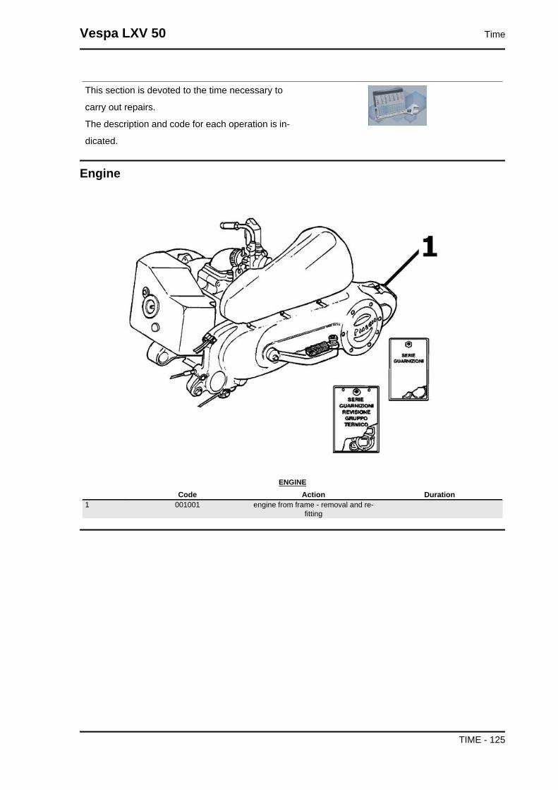
This section is devoted to the time necessary to
carry out repairs.
The description and code for each operation is in-
dicated.
Engine
ENGINECode Action Duration
1 001001 engine from frame - removal and re-fitting
Vespa LXV 50 Time
TIME - 125

Crankcase
CRANKCASECode Action Duration
1 001133 Engine crankcase - Replacement
Time Vespa LXV 50
TIME - 126
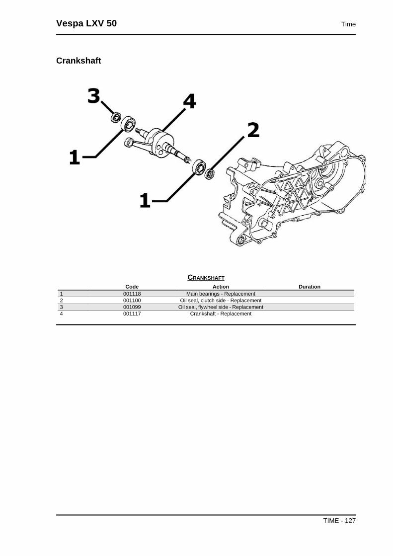
Crankshaft
CRANKSHAFTCode Action Duration
1 001118 Main bearings - Replacement2 001100 Oil seal, clutch side - Replacement3 001099 Oil seal, flywheel side - Replacement4 001117 Crankshaft - Replacement
Vespa LXV 50 Time
TIME - 127

Cylinder assy.
CYLINDER- PISTONCode Action Duration
1 001002 Cylinder-Piston - Replacement2 001107 Cylinder / piston - Inspection / clean-
ing
Time Vespa LXV 50
TIME - 128

Cylinder head assy.
HEADCode Action Duration
1 001097 Cooling hood - Replacement2 001093 Spark plug - Replacement3 001126 Head - Replacement4 001013 Intake manifold - Replacement5 001178 Disc pack - Replacement
Vespa LXV 50 Time
TIME - 129
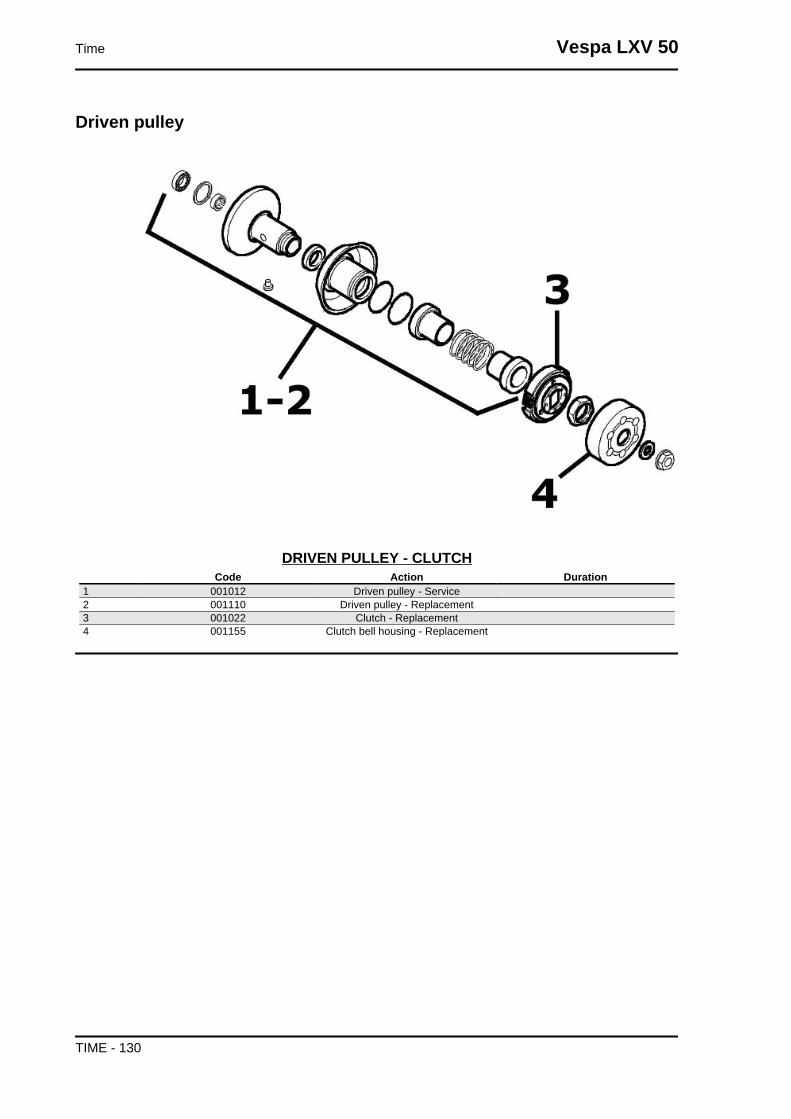
Driven pulley
DRIVEN PULLEY - CLUTCHCode Action Duration
1 001012 Driven pulley - Service2 001110 Driven pulley - Replacement3 001022 Clutch - Replacement4 001155 Clutch bell housing - Replacement
Time Vespa LXV 50
TIME - 130

Oil pump
OIL PUMPCode Action Duration
1 001028 Mix movement gear socket - Re-placement
2 001019 Mixer belt - replacement3 001018 Mixer - Replacement
Vespa LXV 50 Time
TIME - 131
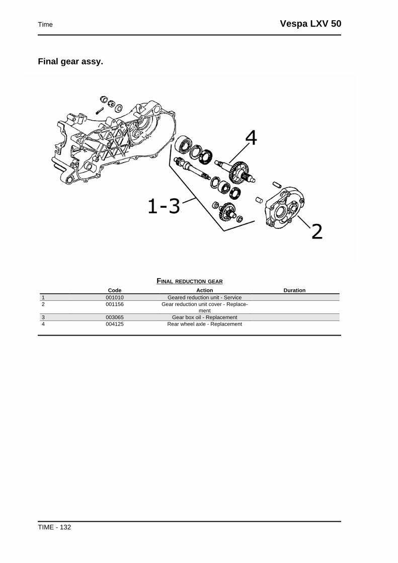
Final gear assy.
FINAL REDUCTION GEARCode Action Duration
1 001010 Geared reduction unit - Service2 001156 Gear reduction unit cover - Replace-
ment3 003065 Gear box oil - Replacement4 004125 Rear wheel axle - Replacement
Time Vespa LXV 50
TIME - 132
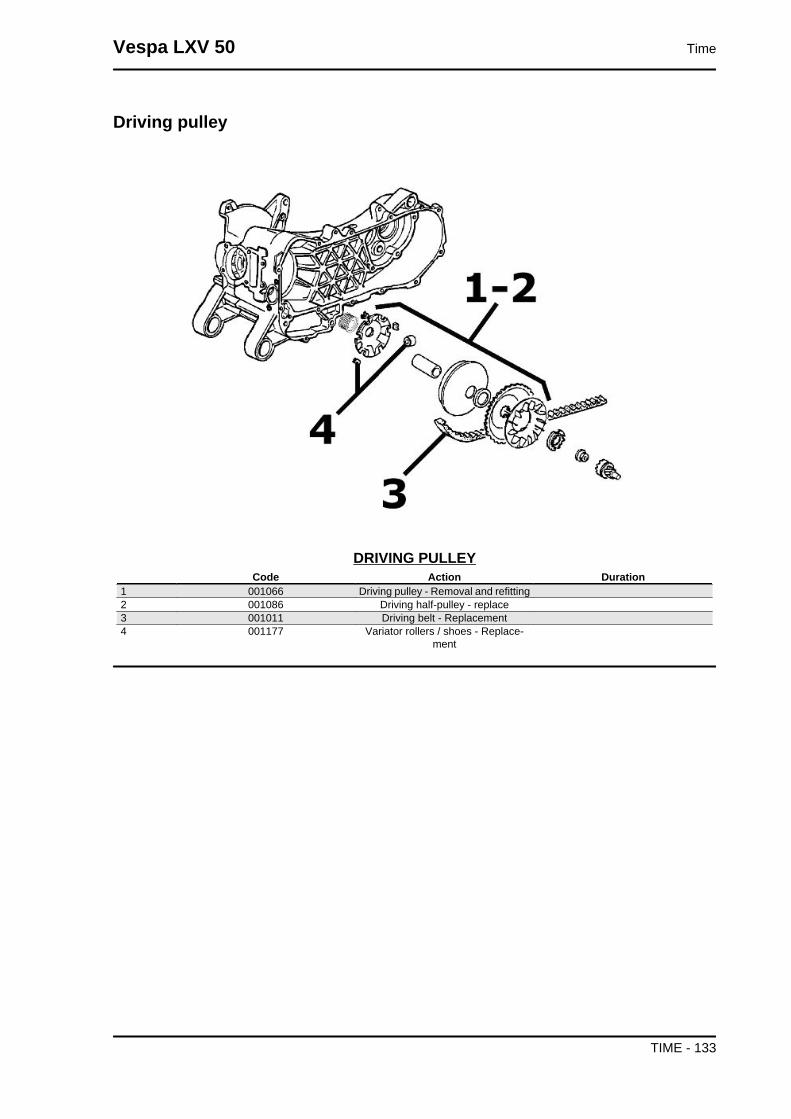
Driving pulley
DRIVING PULLEYCode Action Duration
1 001066 Driving pulley - Removal and refitting2 001086 Driving half-pulley - replace3 001011 Driving belt - Replacement4 001177 Variator rollers / shoes - Replace-
ment
Vespa LXV 50 Time
TIME - 133
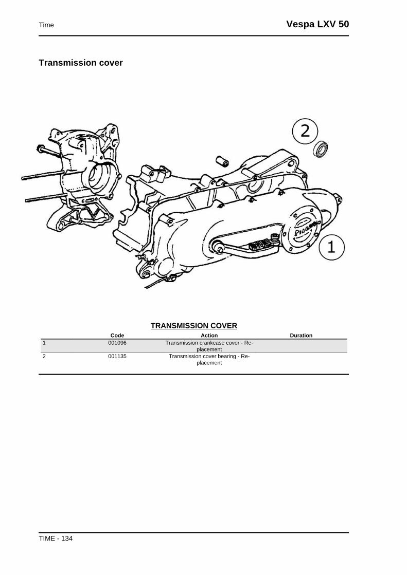
Transmission cover
TRANSMISSION COVERCode Action Duration
1 001096 Transmission crankcase cover - Re-placement
2 001135 Transmission cover bearing - Re-placement
Time Vespa LXV 50
TIME - 134
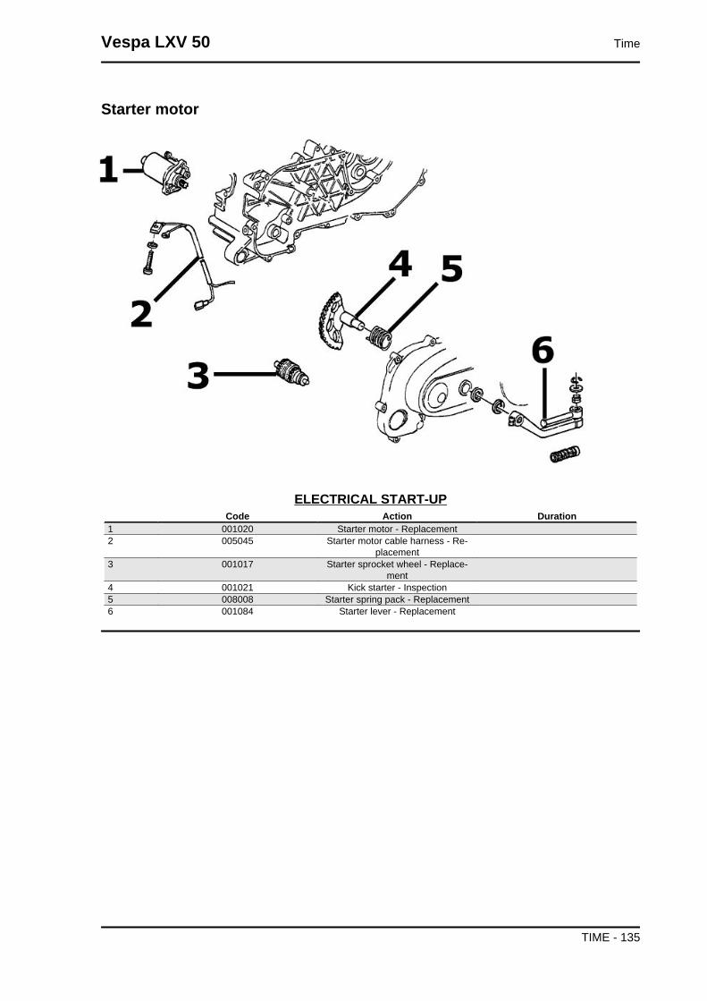
Starter motor
ELECTRICAL START-UPCode Action Duration
1 001020 Starter motor - Replacement2 005045 Starter motor cable harness - Re-
placement3 001017 Starter sprocket wheel - Replace-
ment4 001021 Kick starter - Inspection5 008008 Starter spring pack - Replacement6 001084 Starter lever - Replacement
Vespa LXV 50 Time
TIME - 135

Flywheel magneto
MAGNETO FLYWHEELCode Action Duration
1 001109 Cooling fan - Replacement2 001173 Rotor - Replacement3 001067 Stator - Fitting and Refitting4 001058 Flywheel - Replacement5 001087 Flywheel cover - Replacement
Time Vespa LXV 50
TIME - 136

Carburettor
CARBURETTORCode Action Duration
1 001008 Carburettor - Inspection2 001063 Carburettor - Replacement3 007020 Carburettor heating tubing - replace-
ment4 001081 Automatic choke - Replacement5 001082 Carburettor heating resistor - Re-
placement6 003058 Carburettor - Adjustment7 004177 Heating hood - Replacement
Vespa LXV 50 Time
TIME - 137

Exhaust pipe
MUFFLERCode Action Duration
1 001009 Muffler - Replacement2 001095 Muffler guard - Replacement
Time Vespa LXV 50
TIME - 138

Air cleaner
AIR CLEANERCode Action Duration
1 004122 Air cleaner carburettor fitting - Re-placement
2 001014 Air filter - Replacement / cleaning3 001015 Air filter box - Replacement
Vespa LXV 50 Time
TIME - 139
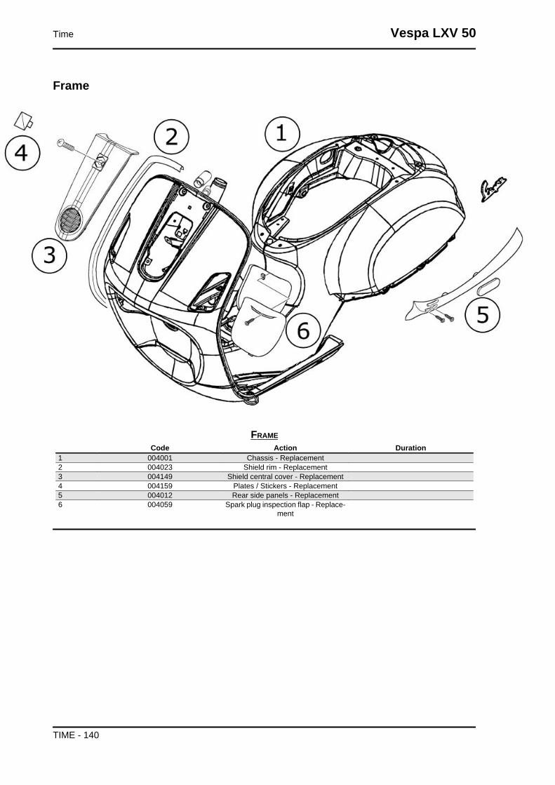
Frame
FRAMECode Action Duration
1 004001 Chassis - Replacement2 004023 Shield rim - Replacement3 004149 Shield central cover - Replacement4 004159 Plates / Stickers - Replacement5 004012 Rear side panels - Replacement6 004059 Spark plug inspection flap - Replace-
ment
Time Vespa LXV 50
TIME - 140

Centre-stand
STANDCode Action Duration
1 004004 Stand - Replacement2 004171 Stand support plate - Replacement
Vespa LXV 50 Time
TIME - 141
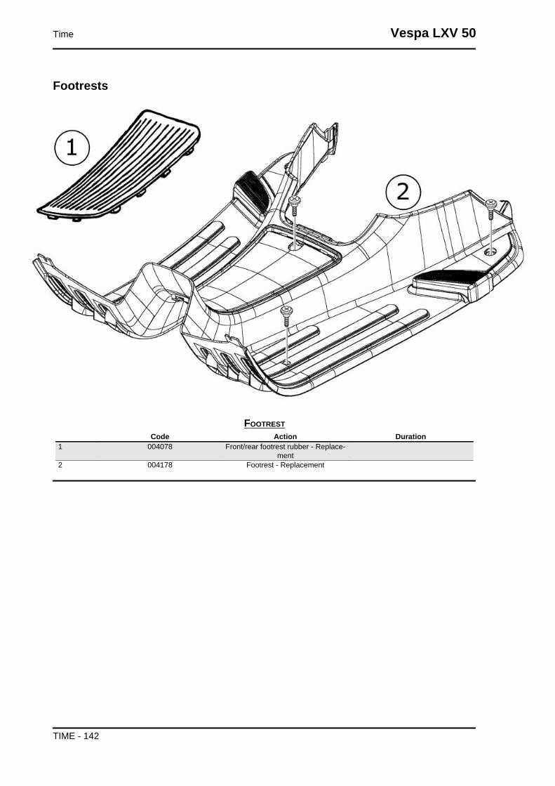
Footrests
FOOTRESTCode Action Duration
1 004078 Front/rear footrest rubber - Replace-ment
2 004178 Footrest - Replacement
Time Vespa LXV 50
TIME - 142
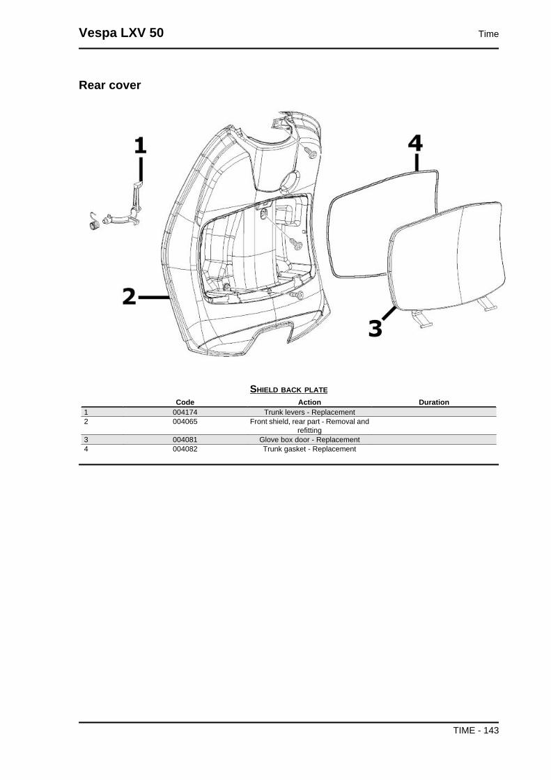
Rear cover
SHIELD BACK PLATECode Action Duration
1 004174 Trunk levers - Replacement2 004065 Front shield, rear part - Removal and
refitting3 004081 Glove box door - Replacement4 004082 Trunk gasket - Replacement
Vespa LXV 50 Time
TIME - 143

Underseat compartment
HELMET COMPARTMENTCode Action Duration
1 004016 Helmet compartment - Replacement2 005046 Battery cover - change3 004011 Central chassis cover - Replacement4 004071 Battery compartment - replacement
Time Vespa LXV 50
TIME - 144

Plate holder
LICENSE PLATE HOLDERCode Action Duration
1 004136 License plate support - Replacement2 005048 Licence plate holder - Replacement3 005032 Licence plate light glass - Replace-
ment
Vespa LXV 50 Time
TIME - 145
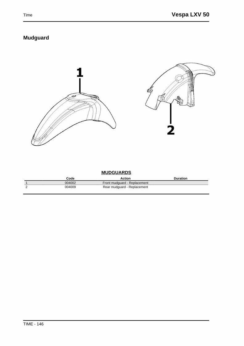
Mudguard
MUDGUARDSCode Action Duration
1 004002 Front mudguard - Replacement2 004009 Rear mudguard - Replacement
Time Vespa LXV 50
TIME - 146
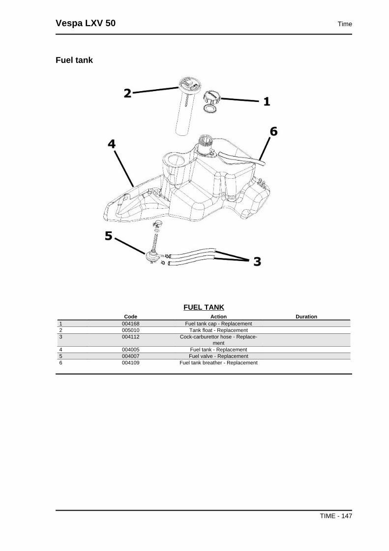
Fuel tank
FUEL TANKCode Action Duration
1 004168 Fuel tank cap - Replacement2 005010 Tank float - Replacement3 004112 Cock-carburettor hose - Replace-
ment4 004005 Fuel tank - Replacement5 004007 Fuel valve - Replacement6 004109 Fuel tank breather - Replacement
Vespa LXV 50 Time
TIME - 147

Tank oil
OIL RESERVOIRCode Action Duration
1 005018 Oil reservoir float - Replacement2 004017 Oil reservoir - Replacement3 004095 Oil reservoir cock - Replacement4 004091 Oil reservoir hose - Replacement
Rear shock-absorber
Time Vespa LXV 50
TIME - 148
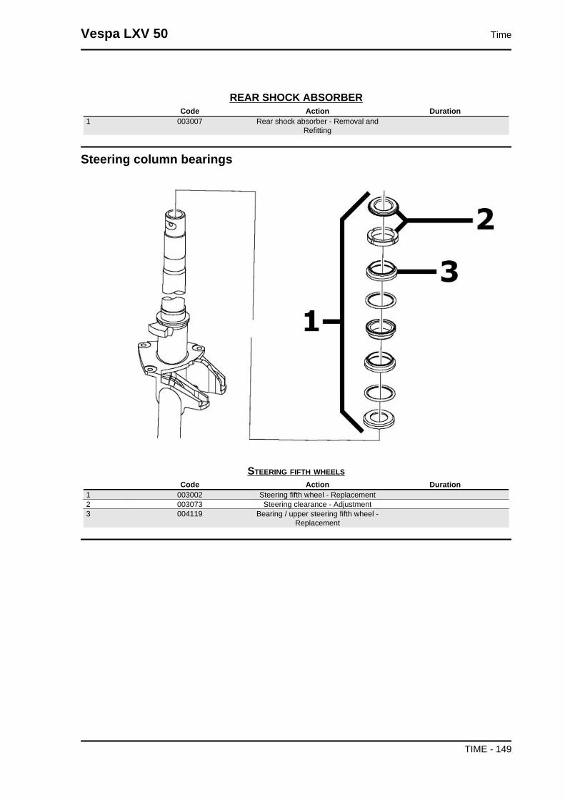
REAR SHOCK ABSORBERCode Action Duration
1 003007 Rear shock absorber - Removal andRefitting
Steering column bearings
STEERING FIFTH WHEELSCode Action Duration
1 003002 Steering fifth wheel - Replacement2 003073 Steering clearance - Adjustment3 004119 Bearing / upper steering fifth wheel -
Replacement
Vespa LXV 50 Time
TIME - 149
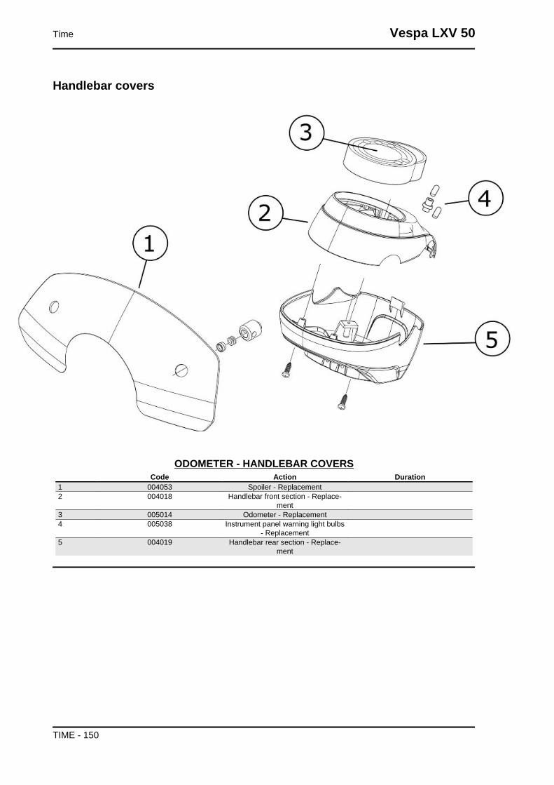
Handlebar covers
ODOMETER - HANDLEBAR COVERSCode Action Duration
1 004053 Spoiler - Replacement2 004018 Handlebar front section - Replace-
ment3 005014 Odometer - Replacement4 005038 Instrument panel warning light bulbs
- Replacement5 004019 Handlebar rear section - Replace-
ment
Time Vespa LXV 50
TIME - 150

Handlebar components
HANDLEBAR COMPONENTSCode Action Duration
1 004066 Driving mirror - Replacement2 002037 Brake or clutch lever - Replacement3 002071 Left hand grip - Replacement4 003001 Handlebar - Replacement5 005017 Stop switch - Replacement6 002024 Front brake pump - Removal and Re-
fitting7 002054 Throttle or splitter transmission com-
plete - Replacement8 002060 Complete throttle control - Replace-
ment9 004162 Mirror support and/or brake pump fit-
ting U-bolt - Replacement10 002059 Right hand grip - Replacement
Vespa LXV 50 Time
TIME - 151
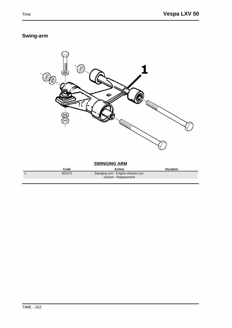
Swing-arm
SWINGING ARMCode Action Duration
1 001072 Swinging arm - Engine-chassis con-nection - Replacement
Time Vespa LXV 50
TIME - 152

Seat
SADDLECode Action Duration
1 004003 Saddle - Replacement2 004008 Luggage rack - Replacement
Vespa LXV 50 Time
TIME - 153

Turn signal lights
TURN INDICATOR LIGHTSCode Action Duration
1 005002 Front headlamp - Replacement2 005012 Front turn indicator - Replacement3 005067 Front turn indicator bulb - Replace-
ment4 005008 Front headlamp bulbs - Replacement5 005005 Taillight - Replacement6 005066 Rear light bulbs - Replacement7 005022 Rear turn indicators - Replacement8 005068 Rear turn indicator bulb - Replace-
ment
Time Vespa LXV 50
TIME - 154
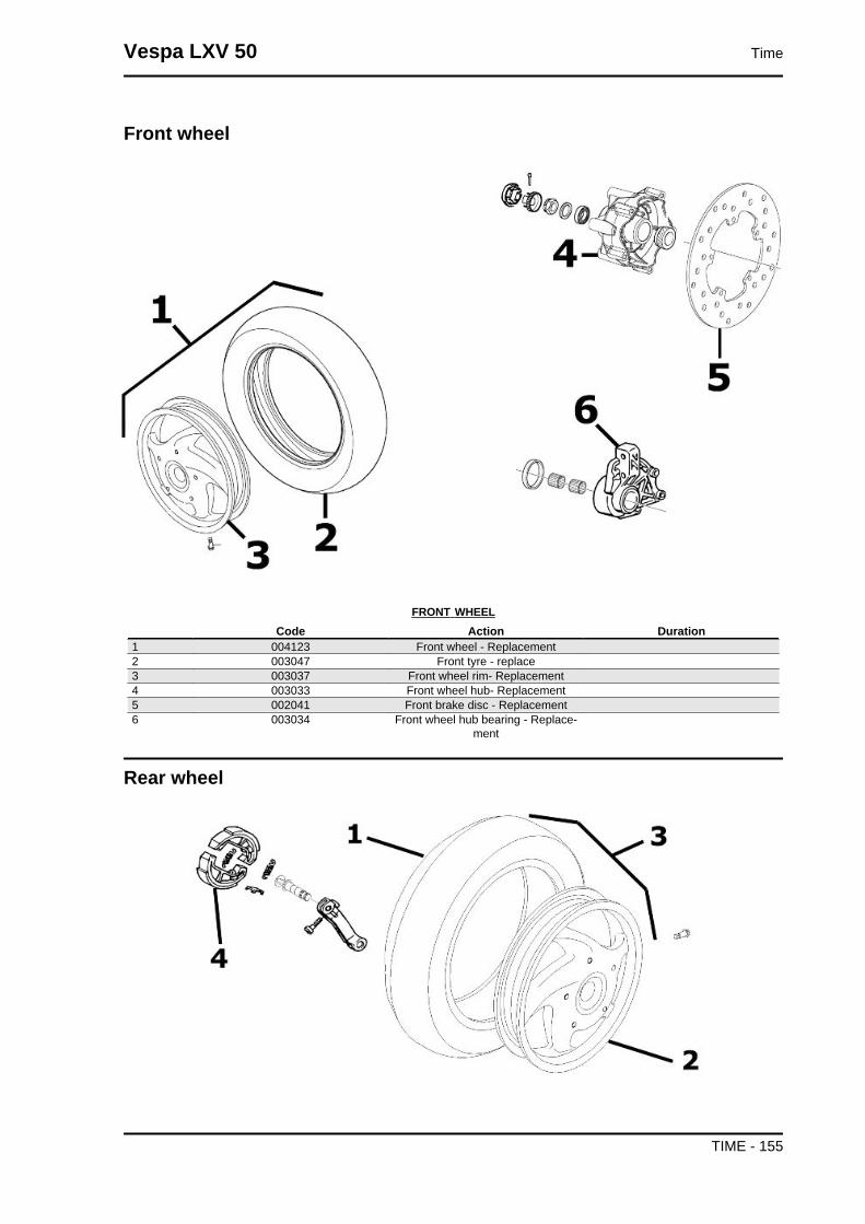
Front wheel
FRONT WHEELCode Action Duration
1 004123 Front wheel - Replacement2 003047 Front tyre - replace3 003037 Front wheel rim- Replacement4 003033 Front wheel hub- Replacement5 002041 Front brake disc - Replacement6 003034 Front wheel hub bearing - Replace-
ment
Rear wheel
Vespa LXV 50 Time
TIME - 155

REAR WHEELCode Action Duration
1 004126 Rear wheel tyre - Replacement2 001071 Rear wheel rim - Removal and Refit-
ting3 001016 Rear wheel - Replacement4 002002 Rear brake pads/shoes - Replace-
ment
Electric devices
ELECTRICAL COMPONENTSCode Action Duration
1 005001 Electrical system - Replacement2 005011 Start-up remote control switch - Re-
placement3 005009 Voltage regulator - Replacement4 005007 Battery - Replacement5 005052 Fuse (1) - Replacement6 001023 Control unit - Replacement7 001094 Spark plug cap - Replacement8 005054 Fuse block (1) - Replacement
Time Vespa LXV 50
TIME - 156
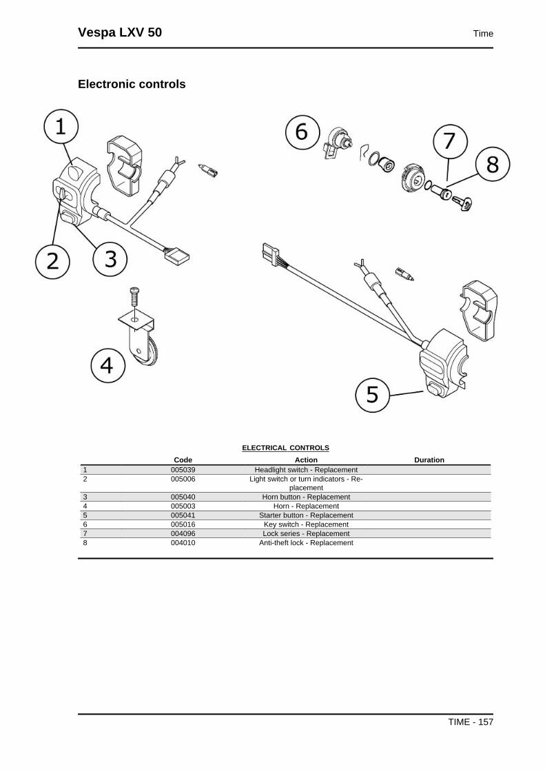
Electronic controls
ELECTRICAL CONTROLSCode Action Duration
1 005039 Headlight switch - Replacement2 005006 Light switch or turn indicators - Re-
placement3 005040 Horn button - Replacement4 005003 Horn - Replacement5 005041 Starter button - Replacement6 005016 Key switch - Replacement7 004096 Lock series - Replacement8 004010 Anti-theft lock - Replacement
Vespa LXV 50 Time
TIME - 157

Transmissions
TRANSMISSIONCode Action Duration
1 002051 Odometer transmission assembly -Replacement
2 002012 Splitter - Replacement3 002057 Carburettor / splitter transmission
complete - Replacement4 002058 Mix / splitter transmission complete -
Replacement5 002053 Rear brake transmission complete -
Replacement6 002049 Odometer cable - Replacement7 003061 Accelerator transmission - Adjust-
ment
Time Vespa LXV 50
TIME - 158

Brake callipers
CALLIPERCode Action Duration
1 002021 Front brake hose - Remov. and Re-fitt.
2 002007 Front brake shoes/pads - Remov.and Refitt
3 002039 Front brake calliper - Removal andRefitting
4 002047 Front brake fluid and air bleedingsystem - Replacement
Vespa LXV 50 Time
TIME - 159

Front suspension
FRONT SUSPENSIONCode Action Duration
1 003045 Steering tube - Replacement2 003010 Front suspension - Service3 003035 Shock absorber support and brake
calliper - Replacement4 001064 Odometer reel - Replacement5 003044 Shock absorber cover - Replace-
ment6 003038 Front wheel axle - Removal and Re-
fit.
Time Vespa LXV 50
TIME - 160
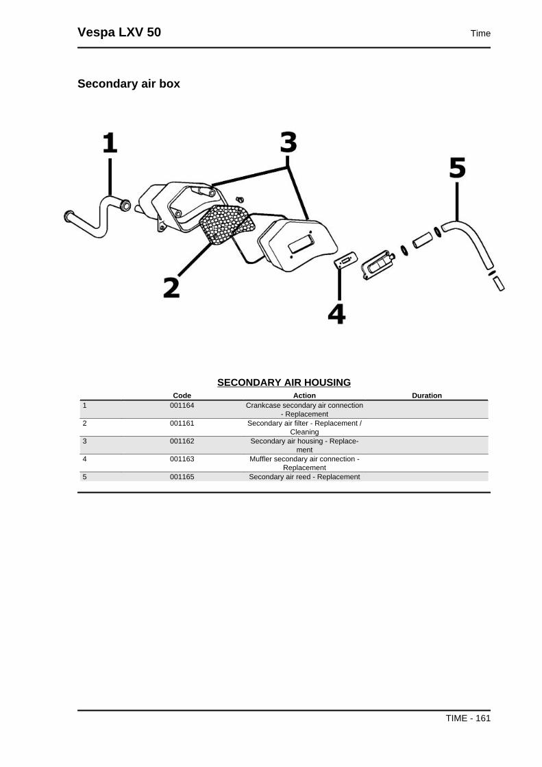
Secondary air box
SECONDARY AIR HOUSINGCode Action Duration
1 001164 Crankcase secondary air connection- Replacement
2 001161 Secondary air filter - Replacement /Cleaning
3 001162 Secondary air housing - Replace-ment
4 001163 Muffler secondary air connection -Replacement
5 001165 Secondary air reed - Replacement
Vespa LXV 50 Time
TIME - 161

AAir filter: 32, 118
BBattery: 40, 47, 55Brake: 109–113, 159
CCarburettor: 11, 29, 137
EEngine stop:
FFuel: 39, 90, 147Fuses: 54
HHeadlight: 35, 117Hub oil: 31
IIdentification: 8Instrument panel: 116
MMaintenance: 7, 27
OOdometer:
SSaddle: Shock absorbers: 106Spark plug: 30Stand: Start-up:
TTank: 147, 148Transmission: 9, 39, 62, 134Tyres: 10