version 8.8 linked capacity plus - support.smartptt.com · mototrbo equipment programming 3 linked...
TRANSCRIPT

Configuration Guide
Linked Capacity Plus
February 2016
Version 8.8

Table of Contents
Linked Capacity Plus 8.8 Configuration Guide
Table of Contents
Linked Capacity Plus
2MOTOTRBO Equipment Programming
4MOTOTRBO Repeater Programming
14MOTOTRBO Radio Programming
22MNIS and DDMS Client Configuration
26SmartPTT Radioserver Configuration
32SmartPTT Dispatcher Configuration

2
Configuration GuideLinked Capacity Plus 8.8
Linked Capacity Plus
To configure Linked Capacity Plus (LCP) system consisting of 3 sites with 2 repeaters on each site, see the
following network scheme:
Each radio ID, either subscriber radio ID or repeater ID should be unique in the radio system. In this example you
can see 2 repeaters with ID's 11 and 12 on Site 1, 2 repeaters with ID's 21 and 22 on Site 2, and 2 repeaters with
ID's 31 and 32 on Site 3. The repeater with ID=31 is a Master.
MOTOTRBO Equipment ProgrammingTo program MOTOTRBO equipment you will need MOTOTRBO Customer Programming Software (CPS).
1. Connect your device to the PC via a programming cable and launch MOTOTRBO CPS.

3MOTOTRBO Equipment Programming
Configuration GuideLinked Capacity Plus 8.8
2. Switch on the device and check its settings by clicking the Read button on the menu bar.
3. In the View menu select Expert to gain access to all the setting parameters.
4. In the Device Information tab make sure that firmware version is no older than:
R01.12.11 or R02.30.10 for mobile or portable radios;
R02.30.12 for repeaters.
Otherwise, contact the supplier to request firmware upgrade.

4MOTOTRBO Equipment Programming
Configuration GuideLinked Capacity Plus 8.8
Note: It is recommended to use the same or compatible firmware versions for all MOTOTRBO equipment on
the same network.
5. To apply the changes in the settings, click Write.
MOTOTRBO Repeater Programming
Note: Only repeaters with 32 MB of internal memory (e.g., DR 3000 or MTR3000) can support the LCP
configuration. Also, make sure that the repeater supports such features as Network Application Interface
Voice, Network Application Interface Data and Capacity Plus (Linked).
First of all, configure the Master repeater parameters. Each LCP system needs one repeater to act as a Master.
The Master repeater has a static IP address, while other repeaters can have either static or dynamic IP
addresses. All the repeaters in the LCP configuration register with the Master using the static IP address of the
Master.

5MOTOTRBO Equipment Programming
Configuration GuideLinked Capacity Plus 8.8
1. In the General Settings tab specify Radio ID and Site ID. In our case Radio ID=31 and Site ID=3.

6MOTOTRBO Equipment Programming
Configuration GuideLinked Capacity Plus 8.8
2. Add parameters in the Network tab.
In the Link Type field select Master.
In the Master IP and Master UDP Port specify the IP address and port number of the Master repeater.
Do not select DHCP. Master IP address should be static.
In the Ethernet IP field specify the IP address of the Master repeater, the same as in the Master IP field.
In the Gateway IP field specify the gateway IP address for the repeater.
In the Gateway Netmask field specify the gateway netmask address for the repeater.

7MOTOTRBO Equipment Programming
Configuration GuideLinked Capacity Plus 8.8
In the UDP Port field specify the UDP port of the repeater. The default value is set to 50000.
3. In the same Network tab specify Rest Channel/Site IP and Rest Channel/Site UDP Port.
Rest Channel/Site IP is a virtual IP address that is required for correct operation of the LCP system. As the Rest
Channel rotates through the channel pool of a site, this virtual IP address is associated with a different physical
repeater only for the duration for which one of its slots is the Rest Channel. This IP address must be the same for
all repeaters at the same site. Rest Channel/Site IP address should be at the same sub network as all repeaters
of this site. No other device should use this IP address.
In the LCP system Rest Channel/Site UDP Port allows the user to configure the UDP port of site for
communication with other sites connected within the LCP system.

8MOTOTRBO Equipment Programming
Configuration GuideLinked Capacity Plus 8.8
4. In the Sites tab set up the site map. In this example we have 3 sites (see the network scheme above). Site 1
has only one neighbor – Site2. Site 2 has 2 neighbors – Site 1 and Site 3. And Site 3 has only one neighbor –
Site 2.
In the Reserved Wide Area ChanneIs column you can specify how many channels are to be reserved for a wide
group call per site, if necessary.
5. In the Talkgroups tab, specify wide groups and sites on which these groups are available. You do not need to
add local groups which are available only on one site.
In our example we have only two wide groups. Group 1 is a wide group which is available on all sites. So when a
subscriber initiates a call to Group 1, this call will be transmitted on all sites. Group 2 is also a wide group and is
available on Site 2 and Site 3.
6. Set up channels. Click on Channels, right-click on Zone, select Add and then Capacity Plus Voice Channel
(Linked) or Capacity Plus Data Channel (Linked). Please remember that both repeater channels will be
used for one and the same purpose. In LCP, a Data Revert Channel can be configured either as a local Data

9MOTOTRBO Equipment Programming
Configuration GuideLinked Capacity Plus 8.8
Revert Channel, or as a wide area Data Revert Channel. In our configuration all repeaters will be used for voice,
that is why in the Master repeater settings we add Capacity Plus Voice Channel (Linked).
7. Specify Color Code and Slot Channel ID.
The color code is used to identify radio systems. Therefore, different color codes are used to identify different
systems. Channels may have the same or different color codes. However, a repeater can only have one color
code. Radios will ignore any channel activity not containing the matching color code for the system. Repeaters
using the same frequency can be associated with different color codes.
Slot 2 Channel ID is set up automatically.
10MOTOTRBO Equipment Programming
Configuration GuideLinked Capacity Plus 8.8
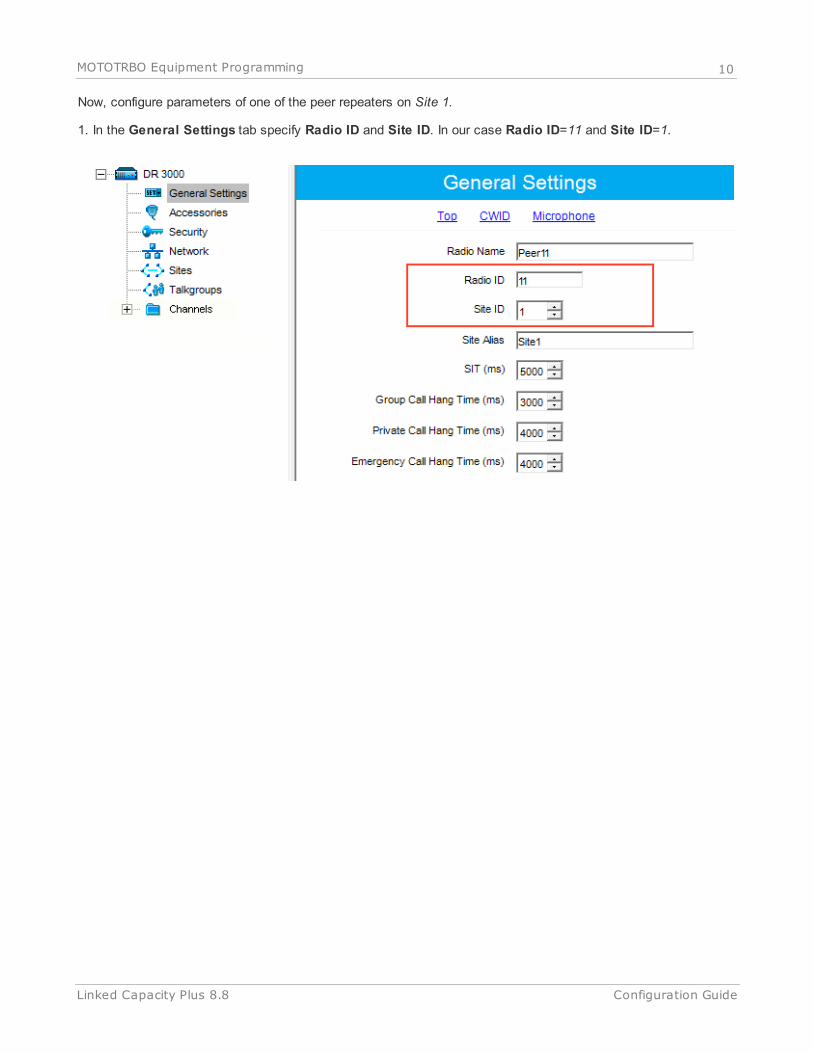
Now, configure parameters of one of the peer repeaters on Site 1.
1. In the General Settings tab specify Radio ID and Site ID. In our case Radio ID=11 and Site ID=1.

11MOTOTRBO Equipment Programming
Configuration GuideLinked Capacity Plus 8.8
2. In the Network tab configure network settings.
In the Link Type field select Peer.
In the Master IP and Master UDP Port specify the IP address and port number of the Master repeater.
Do not select DHCP.
In the Ethernet IP field specify the IP address of the repeater. Master IP address (Site 3) and Peer
repeater IP address (Site 1) will be in different sub networks, because each site should be located in
different sub network.
In the Gateway IP field specify the gateway IP address for the repeater.
In the Gateway Netmask field specify the gateway netmask address for the repeater.
In the UDP Port field specify the UDP port of the repeater. The default value is set to 50000.

12MOTOTRBO Equipment Programming
Configuration GuideLinked Capacity Plus 8.8
3. In the same Network tab specify Rest Channel/Site IP and Rest Channel/Site UDP Port.
Rest Channel/Site IP is configured in each repeater. Repeaters from the same site will have the same Rest
Channel IP address.

13MOTOTRBO Equipment Programming
Configuration GuideLinked Capacity Plus 8.8
4. Add channels. Click on Channels, right-click on Zone, select Add and then Capacity Plus Voice Channel
(Linked). Specify Color Code and Slot Channel ID for each channel.
The Color Code must match the color code set for other repeaters.
When configuring a new site, you need to start numeration with Slot 1 Channel ID=1.
Example:
Site 3 (with Master): 1-2-Master ID=31, 3-4-Peer ID=32,
Site 1: 1-2-Peer ID=11, 3-4-Peer ID=12,
Site 2: 1-2-Peer ID=21, 3-4-Peer ID=22.
Other peer repeaters are configured likewise. When configuring, please keep in mind that:
All repeaters from the same site should be in the same LAN.
Each repeater must have Master IP Address/Port and Rest Channel/Port.

14MOTOTRBO Equipment Programming
Configuration GuideLinked Capacity Plus 8.8
MOTOTRBO Radio Programming
1. In the General Settings specify Radio ID.
Select GPS, if you need to track the subscriber location (only for radios with GPS support DP/DM 3401, 3601,
4401, 4601, DP 4801, SL4010).
Select Private Calls, if radio subscriber needs to transmit private calls. If Private Call is not selected, radio
subscriber won’t be able to initiate a private call, but the user can continue to receive and respond to private calls,
and is still able to initiate call alerts.

15MOTOTRBO Equipment Programming
Configuration GuideLinked Capacity Plus 8.8
2. In the Network tab configure the necessary settings.
In the Forward to PC field select Disabled.
If you plan to work with SmartPTT application specify ARS Radio ID and TMS Radio ID. Remember that
the ARS Radio ID and TMS Radio ID should match the MNIS Radio ID in the MOTOTRBO MNIS
application and Slot ID in SmartPTT Radioserver Configurator. In our case, ARS Radio ID=TMS Radio
ID=Slot ID=MNIS ID=1.

16MOTOTRBO Equipment Programming
Configuration GuideLinked Capacity Plus 8.8
3. In the Contacts tab right-click on the Capacity Plus system to add necessary contacts (Private Call, Group
Call, All Call) to subscriber’s contact list. When configuring the Master repeater, we added 2 groups as wide
groups in the Talkgroups tab. Group 1 with ID=1 is available for all sites, Group 2 with ID=2 is available for
Site 2 and Site 3. Local groups should be added in the radio settings. In this example we will add 4 groups:
Group 1, Group 2 – as wide groups, Group 3 and Group 4 as local groups, and other necessary contacts.
Also, add Dispatcher Call for transmitting data to SmartPTT Radioserver and PC Call to be able to initiate calls
to SmartPTT Dispatcher. Make sure that the IDs of these calls equal Slot ID in SmartPTT Radioserver
Configurator (see SmartPTT Radioserver configuration).

17MOTOTRBO Equipment Programming
Configuration GuideLinked Capacity Plus 8.8
4. Add these groups to the RX List. In our example we use the same RX list for all sites. That is why the RX List
contains all the groups.
5. Add all repeaters, which are in the LCP system, to the Channel Pool. The color code should equal the color
code specified for repeaters. In our case Color Сode=1. Define the RX and TX frequencies. They must
correspond to the frequencies set in the repeater, but RX of the radio must correspond to TX of the repeater and
TX of the radio must correspond to RX of the repeater.

18MOTOTRBO Equipment Programming
Configuration GuideLinked Capacity Plus 8.8
6. Create Voice lists and Data lists according to the amount of sites. As all of our repeaters are Trunk repeaters
(transmit voice and data), create only Voice lists. When adding new Voice list, under the Available list you
can see all the channels which were added to the Channel Pool. So, for Site 1 add a Voice list (LCP Site 1)
and add LCP Site 1-11 and LCP Site 1-12 to this list.
Please note that IDs in the Members list should correspond to Slot 1 ID Channel and Slot 2 ID Channel
specified in repeater settings.
7. Create Voice lists for Site 2 and Site 3 accordingly.

19MOTOTRBO Equipment Programming
Configuration GuideLinked Capacity Plus 8.8
8. Configure Sites lists. If you do not use roaming, create several site lists and add only one site per list.
Since in this example there are three Sites, add three Sites lists.
For each Site configure:
Site ID – ID of the site to which the subscriber radio is connected.
Site Alias – name of the site to which the subscriber radio is connected.
Voice List – Voice Channel List which the subscriber radio will use to make voice calls when on the site.
Data List – Data Channel List which the subscriber radio will use to make data calls when on the site.
RX Group List – RX Group List which the subscriber radio will use to receive group calls when on the site.

20MOTOTRBO Equipment Programming
Configuration GuideLinked Capacity Plus 8.8
If subscriber roams between different sites, one site list will contain several sites.
In our case a subscriber with Radio ID=100 can roam between all three sites, so we created one Sites list with
all the sites.

21MOTOTRBO Equipment Programming
Configuration GuideLinked Capacity Plus 8.8
9. Add LCP Personalities. To do this, right-click on Zone and add Capacity Plus Personality (linked).
For each channel specify:
ARS – select On System/Site Change. ARS feature provides an automatic radio registration. When the
radio powers up, the radio automatically registers with the server. This feature is also used with Text
Messaging or Location Services.
Auto Roam – select Auto Roam if the radio is to roam between sites in the LCP system. If disabled, the

22MOTOTRBO Equipment Programming
Configuration GuideLinked Capacity Plus 8.8
radio subscriber won’t be able to roam to another LCP site when moving from one site to another.
For each channel select appropriate Sites list. The subscriber radio can roam to the sites listed in the
Sites list.
Select Contact Name which defines the call that may be initiated on the channel by pressing the PTT
button, when there are no active calls on the channel.
Select Private Call Confirmed and clear Data Call Confirmed.
MNIS and DDMS Client ConfigurationIn order to process data packets, ARS, Call Alerts, GPS, TMS, it is obligatory to have MOTOTRBO Network
Interface Service Configuration Utility (MNIS) and MOTOTRBO DDMS Administrative Client properly installed and
configured.
Let's start with MOTOTRBO Network Interface Service Configuration Utility (MNIS).
Note: Before configuring, make sure the firmware versions of the repeaters and MOTOTRBO Network Interface
Service are compatible (please find compatibility information in MNIS Release Notes).
1. In the General section in the System Operation Mode field select network type. In our case, it is Linked
Capacity Plus.

23MNIS and DDMS Client Configuration
Configuration GuideLinked Capacity Plus 8.8
2. In the Linked Capacity Plus section set up Master IP Address and Master UDP Port fields. These values
should correspond to the same values in MOTOTRBO CPS and in SmartPTT Radioserver Configurator, which
you will set up later.

24MNIS and DDMS Client Configuration
Configuration GuideLinked Capacity Plus 8.8
3. It is recommended to clear the Data Call Confirmed field in the Advanced section and to specify the identifier
in the MNIS LE ID field explicitly. Make sure MNIS LE ID does not match Peer ID of any repeaters in the
system.
Note: In the Firewall settings add MNIS into the exception list.
DDMS operation is closely connected to MNIS for data exchange (MNIS serves as DDMS Watcher). DDMS filters
ARS packets, received by the repeater, and information on the radio presence in the network is sent to all
systems for further processing.

25MNIS and DDMS Client Configuration
Configuration GuideLinked Capacity Plus 8.8
Therefore, when you configure DDMS settings, make sure that:
1. The PortWatcher field in MOTOTRBO DDMS Administrative Client matches the WatcherPort field in MNIS
settings (Advanced > Network).
2. The PORT SU field (Interfaces > ARS Settings) in MOTOTRBO DDMS Administrative Client matches the
ARS UDP Port field in MOTOTRBO Network Interface Service Configuration Utility (Advanced > Networks).

26SmartPTT Radioserver Configuration
Configuration GuideLinked Capacity Plus 8.8
SmartPTT Radioserver Configuration1. Run SmartPTT Radioserver Configurator, which you have downloaded and installed, as described in SmartPTT
Software Installation.
2. In the setting tree on the left, right-click on NAI Systems, point to Add and click NAI - Linked Capacity Plus.
3. In the opened window specify the following settings of the future LCP network.

27SmartPTT Radioserver Configuration
Configuration GuideLinked Capacity Plus 8.8
Name – add network name.
Network ID – specify unique ID of the network. The network ID must not match any ID of the other
SmartPTT Radioserver networks.
Peer ID – enter unique ID of the virtual repeater in the network. The virtual repeater ID must not match any
of the other repeater IDs in this network.
Interface – specify the IP address of the PC where SmartPTT Radioserver is installed.
Port – set up port number of SmartPTT Radioserver. It should differ from the corresponding ports in other
networks.
Master repeater address (host:port) – specify IP address and port number of the Master repeater (see
Master IP and Master UDP Port in MOTOTRBO CPS). In this example it is 10.150.0.20:50000.
Click Test to check connection between the virtual and Master repeaters.
Authentication Key – enter repeater authorization key (to be equal to the Authentication Key in the
repeater settings in MOTOTRBO CPS). In this example we are not setting any authentication keys.
Voice transmission can be carried out in two ways: via repeaters and via control stations. To transmit
voice via control stations, configure control station parameters and profiles for making private calls. To
transmit voice via repeaters, configure virtual control station channels and talkgroups of the channel. The
number of channels depends on the network type. To ensure data packets transmission over the network,
configure the DDMS and MNIS services. To transmit CSBK commands use control stations for voice
transfer. To transmit data and monitoring data select the corresponding check boxes (Data transmission
and Monitoring). If Data transmission is not selected, all data packets will be gray and no data type
differentiation will be applied in the Monitoring panel in SmartPTT Dispatcher. If Data transmission is
selected, the data packets addressed to you will be defined, and other data packets, not addressed to
you, will be gray.
28SmartPTT Radioserver Configuration
Configuration GuideLinked Capacity Plus 8.8
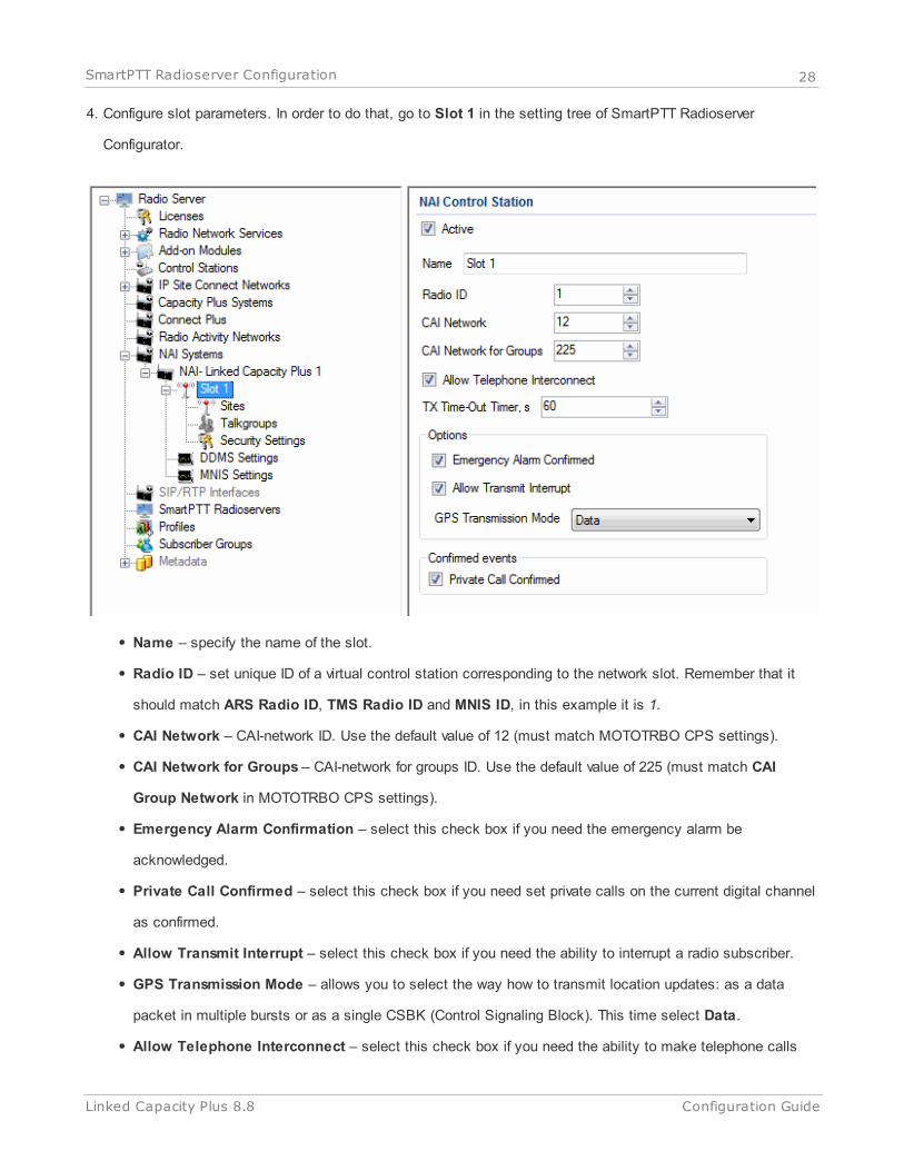
4. Configure slot parameters. In order to do that, go to Slot 1 in the setting tree of SmartPTT Radioserver
Configurator.
Name – specify the name of the slot.
Radio ID – set unique ID of a virtual control station corresponding to the network slot. Remember that it
should match ARS Radio ID, TMS Radio ID and MNIS ID, in this example it is 1.
CAI Network – CAI-network ID. Use the default value of 12 (must match MOTOTRBO CPS settings).
CAI Network for Groups – CAI-network for groups ID. Use the default value of 225 (must match CAI
Group Network in MOTOTRBO CPS settings).
Emergency Alarm Confirmation – select this check box if you need the emergency alarm be
acknowledged.
Private Call Confirmed – select this check box if you need set private calls on the current digital channel
as confirmed.
Allow Transmit Interrupt – select this check box if you need the ability to interrupt a radio subscriber.
GPS Transmission Mode – allows you to select the way how to transmit location updates: as a data
packet in multiple bursts or as a single CSBK (Control Signaling Block). This time select Data.
Allow Telephone Interconnect – select this check box if you need the ability to make telephone calls

29SmartPTT Radioserver Configuration
Configuration GuideLinked Capacity Plus 8.8
on the slot.
5. Configure talkgroup parameters. To do that, click Talkgroups. Parameters of wide area and local groups are
set in the Control Station Talkgroups window. In order to display wide area talkgroups by the SmartPTT
Dispatcher application, add necessary talkgroups in SmartPTT Radioserver Configurator, define group identifiers
which correspond to the identifiers of the wide area groups in the repeater MOTOTRBO CPS settings and
select Wide in the Site Number field. In this example we have two wide area talkgroups and two local
talkgroups, so we add them into SmartPTT Radioserver Configurator.
Talkgroups not specified in the repeater settings are regarded as local groups. Local group call does not go
beyond the site on which the call was initiated.
To add local talkgroups, just add them in SmartPTT Radioserver Configurator, define their identifiers and select
site number from the list in the Site Number field.
Note: Wide area and local talkgroup identifiers must differ.
6. Configure MNIS and DDMS settings for data transmission under MNIS Settings and DDMS Settings.
30SmartPTT Radioserver Configuration
Configuration GuideLinked Capacity Plus 8.8
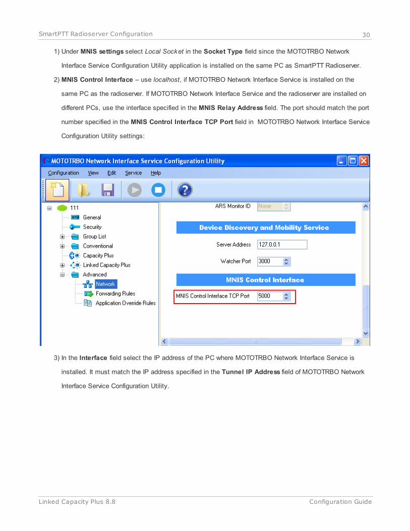
1) Under MNIS settings select Local Socket in the Socket Type field since the MOTOTRBO Network
Interface Service Configuration Utility application is installed on the same PC as SmartPTT Radioserver.
2) MNIS Control Interface – use localhost, if MOTOTRBO Network Interface Service is installed on the
same PC as the radioserver. If MOTOTRBO Network Interface Service and the radioserver are installed on
different PCs, use the interface specified in the MNIS Relay Address field. The port should match the port
number specified in the MNIS Control Interface TCP Port field in MOTOTRBO Network Interface Service
Configuration Utility settings:
3) In the Interface field select the IP address of the PC where MOTOTRBO Network Interface Service is
installed. It must match the IP address specified in the Tunnel IP Address field of MOTOTRBO Network
Interface Service Configuration Utility.

31SmartPTT Radioserver Configuration
Configuration GuideLinked Capacity Plus 8.8
4) In the MNIS ID field set up the Common Air Interface (CAI) ID of the MNIS in the radio network. The ID is
used by other calling radios when addressing MOTOTRBO Network Interface Service. Make sure MNIS ID
matches the MNIS Application ID field in the General tab in MOTOTRBO Network Interface Service
Configuration Utility. It is also recommended that MNIS ID should match Radio ID in the radioserver slot
settings.
5) In the TMS Port, Telemetry Port and Location Port fields specify ports where the radioserver will expect
text messages, telemetry and GPS data. The ports should match the ports set in the TMS UDP PORT,
Telemetry UDP Port, Location Server UDP Port fields in MOTOTRBO Network Interface Service
Configuration Utility (Advanced > Network).
6) Under DDMS settings specify Server Address, i.e., IP address of the PC with the MOTOTRBO DDMS
Administrative Client application installed, and port number of the DDMS server. In this case the DDMS
server is installed on the same PC as the radioserver. The port number in this field must match the port
number in the PortWatcher field of the MOTOTRBO DDMS Administrative Client (Interfaces > Watcher
Settings).

32SmartPTT Radioserver Configuration
Configuration GuideLinked Capacity Plus 8.8
7. Save changes by clicking Save . To cancel the changes made, click the Restore button . All the
changes, made after the last save, will be restored.To apply the saved changes you must restart the service.
The service is managed using the following buttons: Start , Stop and Restart .
SmartPTT Dispatcher ConfigurationIn this topic you will learn how to configure general settings of the SmartPTT Dispatcher console. The general
configuration in the scope of the LCP or Connect Plus network implies that operators will be able to communicate
with radio subscribers and the radio subscribers will be able to communicate with each other.
The general configuration of the SmartPTT Dispatcher console includes the following steps:
1. License installation
2. Database creation
3. Radioserver configuration
4. Audio setting configuration
5. Registration of radio subscribers
The description of the steps is given below:
1. Expand the Settings menu in the Main Menu bar of the SmartPTT Dispatcher window and click Licenses.
Install the required license. After uploading the license, click Finish to apply.
2. Expand the Settings menu in the Main Menu bar of the SmartPTT Dispatcher window and click Database. In
the opened window create the new database and then connect to it.
To create a new database, fill in the Database Server Name and click Create New Database. For a database
server installed together with the SmartPTT dispatcher application enter the name using the format: Name of PC
\SQLExpress (for example, MYCOMP\SQLExpress).
In the window that opened enter the name of the new database and click Save.

33SmartPTT Dispatcher Configuration
Configuration GuideLinked Capacity Plus 8.8
If creation was successful, a message about successful database creation is displayed. If the database is not
created, the reason will be displayed at the bottom of the window.
Authorization Mode – allows you to select authorization mode with the database.
SQL Server Authorization – you must have the login and password of the account which has access to the
SQL server.
Windows NT Authorization – the user who has logged into the Windows system, must be listed in the SQL
server’s list of users to make connection.
After you have finished, click Finish to save the changes. You will need to restart SmartPTT Dispatcher to apply

34SmartPTT Dispatcher Configuration
Configuration GuideLinked Capacity Plus 8.8
the changes.
3. In the Settings menu click Radioservers to add the radioserver and configure it properly.
Click Add to open the window for adding radioservers to the list.

35SmartPTT Dispatcher Configuration
Configuration GuideLinked Capacity Plus 8.8
Enter the name of the radioserver in the Name field. The name will be displayed in the SmartPTT Dispatcher
console.
In the Address and Port fields enter the radioserver IP address and port number to connect with the dispatcher.
To find out the radioserver IP run the ipconfig command on the PC where the radioserver is installed. The default
radioserver port number is 8888.
Select the Active check box to enable the radioserver.
For more information about the radioserver settings see Help in the SmartPTT Dispatcher application.
4. Audio setting configuration is required to give the operator the ability to communicate with the radio
subscribers. Expand the Settings menu in the Main Menu bar of the SmartPTT Dispatcher window and click
Sound.

36SmartPTT Dispatcher Configuration
Configuration GuideLinked Capacity Plus 8.8
Audio Input – audio device to which the microphone is connected.
Input Line – audio mixer line used to connect a microphone.
Audio Output – audio device to which headsets or speakers are connected.
Codec – audio stream compression method.
Bitrate – audio stream sampling frequency.
VoIP Port – audio stream receive port.
Specifications of the codec format 8000 Hz, 20 ms, 64 (86) kbps:
8000Hz – the sampling rate.
20 ms – the frame size.
64 kbps – the voice data bit rate.
86 kbps – a full bit rate (required network bandwidth).
For more information see Help in the SmartPTT Dispatcher application.
5. Register radio subscribers. Unregistered radio subscribers are displayed in italics in the Radio Fleet window
and are not recorded into the database.

37SmartPTT Dispatcher Configuration
Configuration GuideLinked Capacity Plus 8.8
To register the radio subscriber, right-click on the radio subscriber, enter the name and click Save.