version 1 - avery weigh-tronix · pdf filegse model 355, 465 and 562 check weighers users...
TRANSCRIPT

GSE
Model 355, 465 and 562 Check Weighers
Users Guide Version 1.0


GSE Check Weighers
Users Guide
Version 1.0


SPX GSE Check Weighers Users Guide Copyright © 2006 GSE Scale Systems. All rights reserved. Published by: SPX GSE 1525 Fairlane Circle, Suite 300 Allen Park, MI 48101 USA Information in this Users Guide is subject to change without notice due to correction or enhancement. The information described in this manual is solely the property of GSE. No part of this manual may be reproduced or transmitted in any form or by any means, electronic or mechanical, including photocopying and recording and sold for any monetary figure without the express written permission of GSE. GSE Locations SPX GSE 1525 Fairlane Circle, Suite 300 Allen Park, MI 48101 U.S.A. Phone: (800) 755-7875 www.gse-inc.com SPX GSE AMPROBE EUROPE GMBH Phone: +49 (0) 2161-59906-11 Fax: +49 (0) 2161-59906-20


i
Table of Contents
CHAPTER 1: INTRODUCTION ......................................................... 1 SPECIFICATIONS ................................................................................... 1
CHAPTER 2: INSTALLATION.......................................................... 3 OUT OF BOX SETUP .............................................................................. 3 STACK LIGHT OPTION INSTALLATION .................................................. 3
Model 355 Installation.................................................................... 4 Wiring the Stack Light .................................................................... 6 Model 465 Installation.................................................................... 7 Model 562 Installation.................................................................... 9
CHAPTER 3: MODEL 355 SETUP ................................................... 11 INTRODUCTION................................................................................... 11
Display.......................................................................................... 11 Keypad .......................................................................................... 12
CHECKWEIGHING METHOD EXAMPLES .............................................. 12 SETUP................................................................................................. 16
Access Checkweighing Methods ................................................... 16 Enter Target and Limits in the Setup Mode .................................. 16 Save the Changes .......................................................................... 16 Enter Target Value and Limits From the Weigh Mode................. 17
PARTS COUNTING............................................................................... 17 Enable Count Mode (Quantity)..................................................... 18 Save the Changes .......................................................................... 18 Counting Methods......................................................................... 18
CHAPTER 4: MODEL 465 SETUP ................................................... 19 Display.......................................................................................... 19 Keypad .......................................................................................... 19
CHECKWEIGHING METHOD CHOICES.................................................. 20 Fixed Limit.................................................................................... 20 % of Targ ...................................................................................... 20
STATUS INDICATION........................................................................... 21 OPERATING MODE CHOICES............................................................... 22
NET MODE................................................................................... 22 GROSS MODE.............................................................................. 22 COUNT MODE............................................................................. 22
SETUP (F1) ......................................................................................... 23 View Method and Operating Mode............................................... 23

ii
Set Method and Operating Mode ..................................................23 SET TARGET AND LIMITS (TARGET) ...................................................24
Enter a Known Target Value.........................................................24 SET A PASSWORD CODE......................................................................25 PRODUCT ID .......................................................................................25
Quick Recall by ID Number: .........................................................25 Recall by Product ID or Product Name: .......................................26
CHAPTER 5: MODEL 562 SETUP....................................................27 DISPLAY .............................................................................................27 KEYPAD ..............................................................................................27 PARAMETER MAP ...............................................................................28 SET TARGET (F1) ................................................................................29
Enter a Known Target Value.........................................................29 SETUP MODE (F2)...............................................................................30
Operating Mode (1).......................................................................30 Over / Under Target (2) ................................................................32 Display Style (3) ............................................................................33 Based On (4)..................................................................................34
PRODUCT ID (F3)................................................................................35 Access an Existing Product ID ......................................................36
SET TARGET OR UNDER/OVER LIMITS................................................37 SET A PASSWORD CODE......................................................................37
CHAPTER 6: CALIBRATION ...........................................................39 MODEL 355 CHECKWEIGHER ..............................................................39
Access Calibration ........................................................................39 Performing Calibration.................................................................39 Establishing Zero ..........................................................................39 First Zero ......................................................................................40 Last Zero .......................................................................................40 False Zero .....................................................................................41 Only Zero.......................................................................................42 Reset Calibration...........................................................................43 Exiting Calibration........................................................................44
MODEL 465 AND 562 CHECKWEIGHER................................................46 Performing Calibration.................................................................46 Establishing Zero ..........................................................................46 New Zero .......................................................................................46 Last Zero .......................................................................................47 Temp Zero? ...................................................................................48 Only Zero?.....................................................................................48 Cal Reset .......................................................................................49 Exiting Calibration........................................................................50

iii
CHAPTER 7: ERROR CODES ......................................................... 51 MODEL 355 ........................................................................................ 51 MODEL 465 AND 562.......................................................................... 55

1
CHAPTER 1: INTRODUCTION
The Model 355, 465 and 562 Checkweighers are an alliance between high quality, reliable GSE indicators and the Model 4700 scale base.
This manual contains information on the setup and operation of the Model 355, 465 and 562 checkweighers.
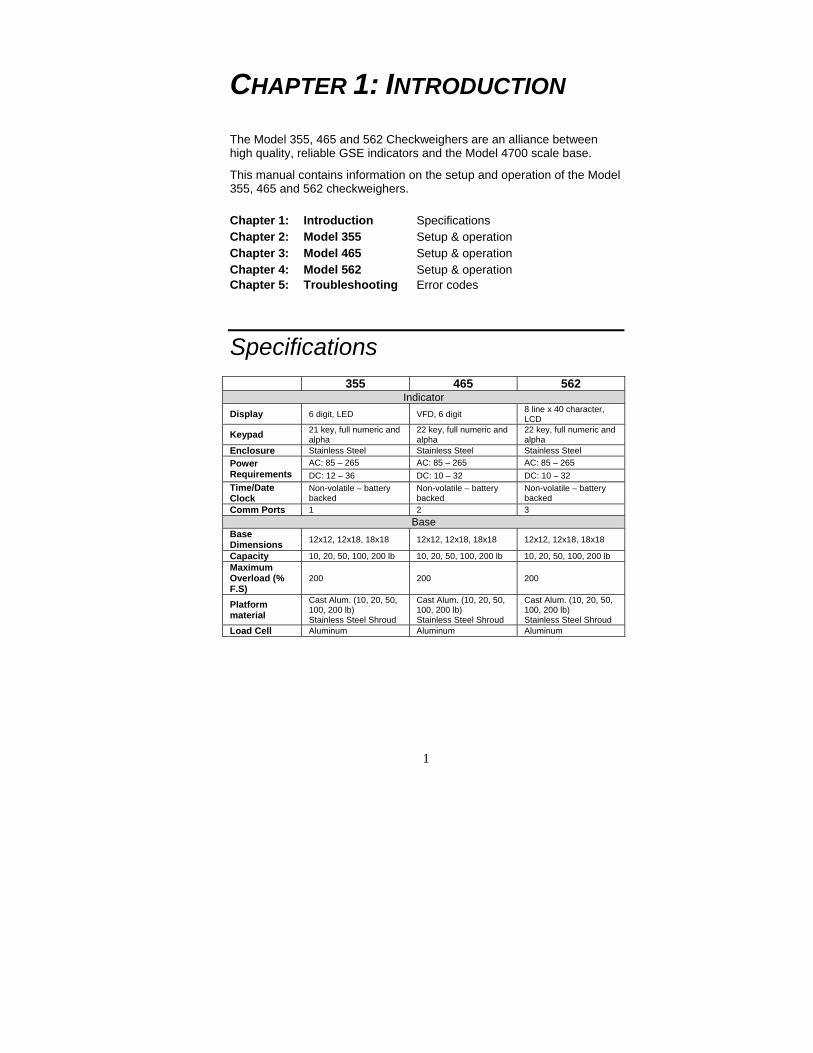
Specifications 355 465 562
Indicator Display 6 digit, LED VFD, 6 digit 8 line x 40 character,
LCD
Keypad 21 key, full numeric and alpha
22 key, full numeric and alpha
22 key, full numeric and alpha
Enclosure Stainless Steel Stainless Steel Stainless Steel AC: 85 – 265 AC: 85 – 265 AC: 85 – 265 Power
Requirements DC: 12 – 36 DC: 10 – 32 DC: 10 – 32 Time/Date Clock
Non-volatile – battery backed
Non-volatile – battery backed
Non-volatile – battery backed
Comm Ports 1 2 3 Base
Base Dimensions 12x12, 12x18, 18x18 12x12, 12x18, 18x18 12x12, 12x18, 18x18
Capacity 10, 20, 50, 100, 200 lb 10, 20, 50, 100, 200 lb 10, 20, 50, 100, 200 lb Maximum Overload (% F.S)
200 200 200
Platform material
Cast Alum. (10, 20, 50, 100, 200 lb) Stainless Steel Shroud
Cast Alum. (10, 20, 50, 100, 200 lb) Stainless Steel Shroud
Cast Alum. (10, 20, 50, 100, 200 lb) Stainless Steel Shroud
Load Cell Aluminum Aluminum Aluminum
Chapter 1: Introduction Specifications Chapter 2: Model 355 Setup & operation Chapter 3: Model 465 Setup & operation Chapter 4: Model 562 Setup & operation Chapter 5: Troubleshooting Error codes


3
CHAPTER 2: INSTALLATION
Out of Box Setup The checkweigher is fully assembled at GSE. Simply take the checkweigher out of the box and start using it. Refer to the rest of the manual for operating your GSE checkweigher.
Stack Light Option Installation The Stack Light Option is offered for enhanced status visibility.
If the Stack Light Option is ordered with the checkweigher, the option is installed by GSE. Otherwise, follow the instructions in this section for setpoint board installation and wiring.
Before installing the Stack Light Option read the warning below.
The GSE indicators contain components which could be damaged by Electrostatic Discharge (ESD) if serviced improperly. Use proper ESD precautions (wear a wrist strap connected to ground, use grounded work stations, etc.) when opening the enclosure. High voltages may exist within the enclosure! To prevent the risk of electrical shock, ALWAYS unplug the indicator when opening the enclosure. Installation and servicing of the indicator should be performed by authorized and qualified service personnel only.
Never connect or disconnect option board cables while the indicator is powered. Doing so may result in circuit board damage.

4
MODEL 355 INSTALLATION
INSTALLING THE SETPOINT BOARD 1. Open the indicator by removing the eight screws from the back of
the unit. 2. Locate the option mounting holes by lining up the option card with
the four holes to the left of the power supply section on the main board. Refer to Figure 1.
3. Install (4) nylon standoffs supplied with the option kit into the thru-holes on the main board.
4. Place the option card on the (4) nylon standoffs installed in step 3. 5. Fasten the option card to the standoffs with the (4) nylon nuts
supplied with the option kit. 6. Tighten the stand-offs gently with a 8 mm hex nut driver. 7. If this is the only option card being installed, attach the loose end of
the cable on the option card to the serial I/O connector (J3) on the main board. J3 is a 10-pin polarized connector. Skip ahead to step 8. ~ OR ~ If a second option is being installed, locate the option mounting holes surrounding the A/D can on the main board. Follow steps 3 - 5 to install the second option card. Connect the loose end of the cable of the second option card to (J3) of the main board. Connect the loose end of the cable of the first option card to J1 of the second option card.
8. The cable from the stack light will need to be connected. Refer to the instructions for stack light installation and wiring on the following pages.
9. Leave the back panel off of the indicator and proceed to the instructions for Installing the Stack Light.
Figure 1: Model 355 Option Installation
5
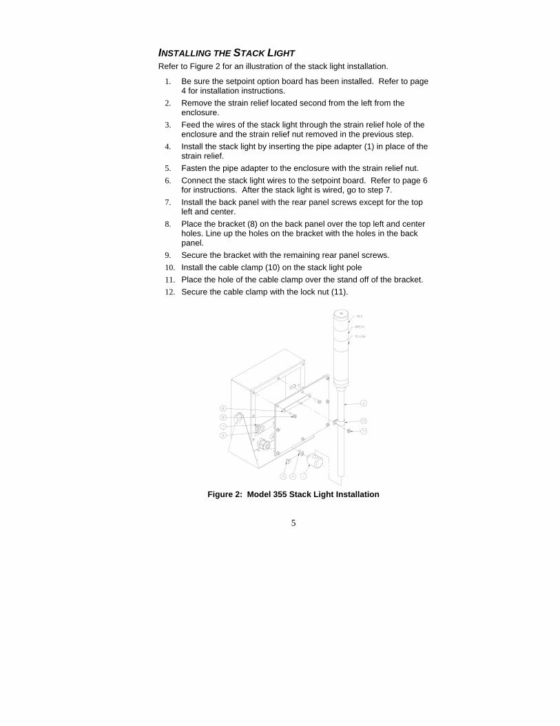
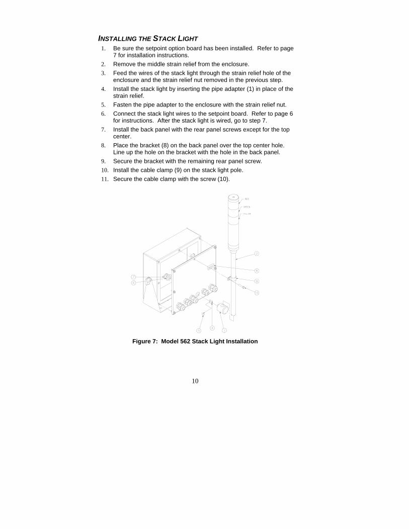
INSTALLING THE STACK LIGHT Refer to Figure 2 for an illustration of the stack light installation.
1. Be sure the setpoint option board has been installed. Refer to page 4 for installation instructions.
2. Remove the strain relief located second from the left from the enclosure.
3. Feed the wires of the stack light through the strain relief hole of the enclosure and the strain relief nut removed in the previous step.
4. Install the stack light by inserting the pipe adapter (1) in place of the strain relief.
5. Fasten the pipe adapter to the enclosure with the strain relief nut. 6. Connect the stack light wires to the setpoint board. Refer to page 6
for instructions. After the stack light is wired, go to step 7. 7. Install the back panel with the rear panel screws except for the top
left and center. 8. Place the bracket (8) on the back panel over the top left and center
holes. Line up the holes on the bracket with the holes in the back panel.
9. Secure the bracket with the remaining rear panel screws. 10. Install the cable clamp (10) on the stack light pole 11. Place the hole of the cable clamp over the stand off of the bracket. 12. Secure the cable clamp with the lock nut (11).
Figure 2: Model 355 Stack Light Installation

6
WIRING THE STACK LIGHT The stack light is wired to the setpoint option board to control the lights. Refer to page 4 for setpoint option board installation instructions. The setpoint option must be installed before connecting the wires.
1. Insert the red stack light wire into the 1+ position of the setpoint board connector.
2. Insert the green stack light wire into the 2+ position of the setpoint board connector.
3. Insert the orange stack light wire into the 3+ position of the setpoint board connector.
4. Connect the black wire from the connector to 1- of the setpoint board connector.
5. Connect the black jumper wires between 1- to 2- and 2- to 3-. Refer to Figure 3.
6. Connect the two pin connector to J3 (Model 355), J10 (Model 465) or J13 (Model 562) on the main board.
Figure 3: Stack Light Wiring
Wire Color Connection Setpoint Setpoint
Position Red Red light 1 +
Green Green Light 2 + Orange Yellow Light 3 +
7
MODEL 465 INSTALLATION
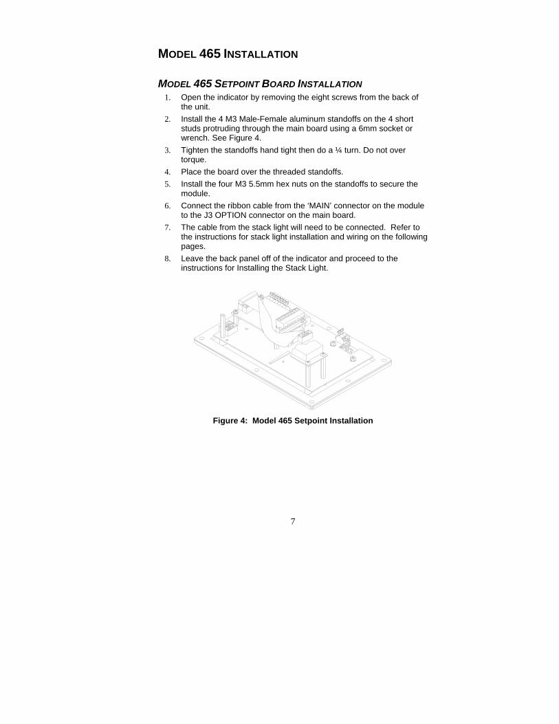
MODEL 465 SETPOINT BOARD INSTALLATION 1. Open the indicator by removing the eight screws from the back of
the unit. 2. Install the 4 M3 Male-Female aluminum standoffs on the 4 short
studs protruding through the main board using a 6mm socket or wrench. See Figure 4.
3. Tighten the standoffs hand tight then do a ¼ turn. Do not over torque.
4. Place the board over the threaded standoffs. 5. Install the four M3 5.5mm hex nuts on the standoffs to secure the
module. 6. Connect the ribbon cable from the ‘MAIN’ connector on the module
to the J3 OPTION connector on the main board. 7. The cable from the stack light will need to be connected. Refer to
the instructions for stack light installation and wiring on the following pages.
8. Leave the back panel off of the indicator and proceed to the instructions for Installing the Stack Light.
Figure 4: Model 465 Setpoint Installation

8
INSTALLING THE STACK LIGHT 1. Be sure the setpoint option board has been installed. Refer to page
7 for installation instructions. 2. Remove the middle strain relief from the enclosure. 3. Feed the wires of the stack light through the strain relief hole of the
enclosure and the strain relief nut removed in the previous step. 4. Install the stack light by inserting the pipe adapter (1) in place of the
strain relief. 5. Fasten the pipe adapter to the enclosure with the strain relief nut. 6. Connect the stack light wires to the setpoint board. Refer to page 6
for instructions. After the stack light is wired, go to step 7. 7. Install the back panel with the rear panel screws except for the top
center. 8. Place the bracket (8) on the back panel over the top center hole.
Line up the hole on the bracket with the hole in the back panel. 9. Secure the bracket with the remaining rear panel screw. 10. Install the cable clamp (10) on the stack light pole. 11. Secure the cable clamp with the screw (9).
Figure 5: Model 465 Stack Light Installation
9
MODEL 562 INSTALLATION
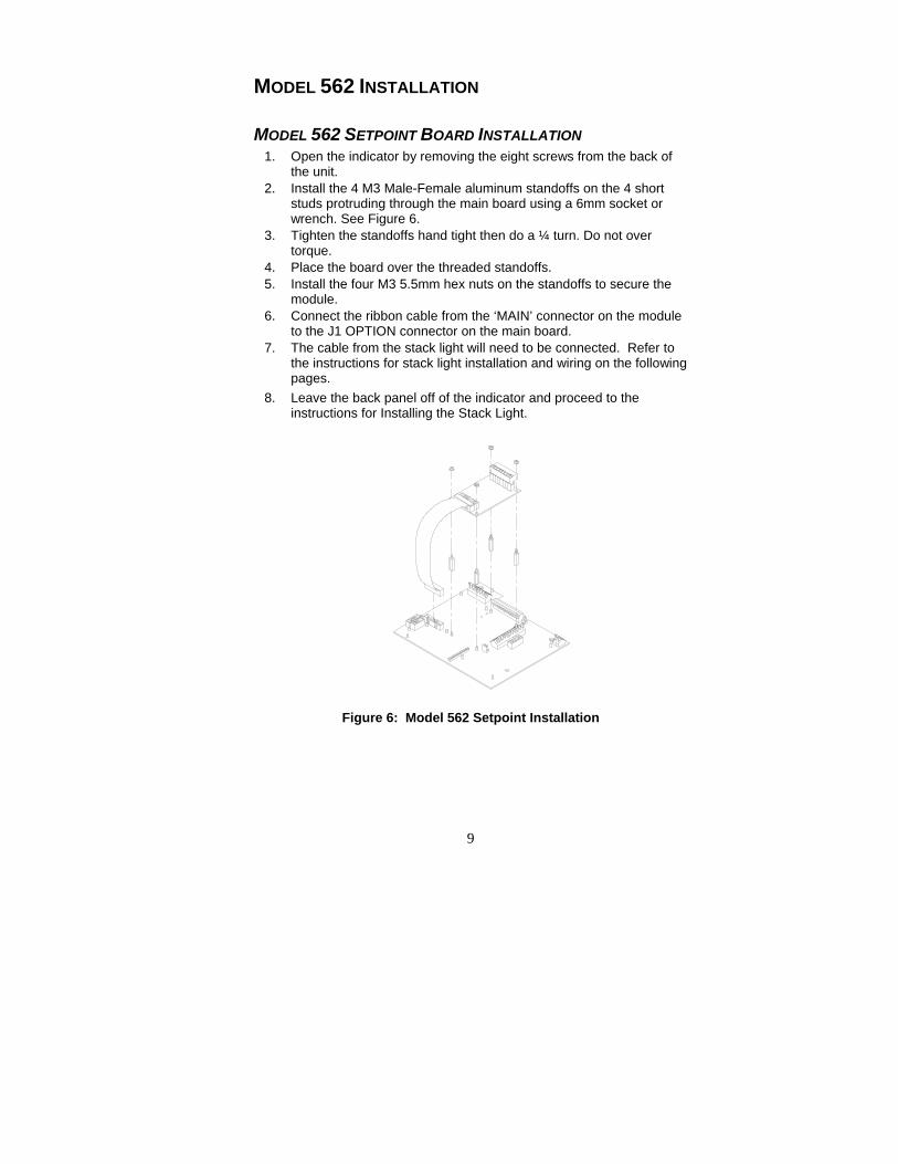
MODEL 562 SETPOINT BOARD INSTALLATION 1. Open the indicator by removing the eight screws from the back of
the unit. 2. Install the 4 M3 Male-Female aluminum standoffs on the 4 short
studs protruding through the main board using a 6mm socket or wrench. See Figure 6.
3. Tighten the standoffs hand tight then do a ¼ turn. Do not over torque.
4. Place the board over the threaded standoffs. 5. Install the four M3 5.5mm hex nuts on the standoffs to secure the
module. 6. Connect the ribbon cable from the ‘MAIN’ connector on the module
to the J1 OPTION connector on the main board. 7. The cable from the stack light will need to be connected. Refer to
the instructions for stack light installation and wiring on the following pages.
8. Leave the back panel off of the indicator and proceed to the instructions for Installing the Stack Light.
Figure 6: Model 562 Setpoint Installation
10
INSTALLING THE STACK LIGHT 1. Be sure the setpoint option board has been installed. Refer to page
7 for installation instructions. 2. Remove the middle strain relief from the enclosure. 3. Feed the wires of the stack light through the strain relief hole of the
enclosure and the strain relief nut removed in the previous step. 4. Install the stack light by inserting the pipe adapter (1) in place of the
strain relief. 5. Fasten the pipe adapter to the enclosure with the strain relief nut. 6. Connect the stack light wires to the setpoint board. Refer to page 6
for instructions. After the stack light is wired, go to step 7. 7. Install the back panel with the rear panel screws except for the top
center. 8. Place the bracket (8) on the back panel over the top center hole.
Line up the hole on the bracket with the hole in the back panel. 9. Secure the bracket with the remaining rear panel screw. 10. Install the cable clamp (9) on the stack light pole. 11. Secure the cable clamp with the screw (10).
Figure 7: Model 562 Stack Light Installation

11
CHAPTER 3: MODEL 355 SETUP
Introduction The Model 355 CheckWeigher is an integrated indicator and scale base. The Model 355 indicator has three different checkweighing methods to choose from to accommodate most checkweighing needs (see page 12 for examples).
DISPLAY Model 355 checkweigher is available with a 6 digit, 7-segment green LED display. The Model 355 will display alphanumeric data, but due to the nature of 7-segment LEDs and the limitation of six digits, some information is abbreviated.
All segments and annunciators are illuminated for a brief display test upon power up. The current gross weight is then displayed in default units.
ANNUNCIATORS Annunciators provide mode and status information. When illuminated, they indicate the following conditions:
SP1 (Red) Current weight is over the high limit tolerance. SP2 (Green) Current weight is within tolerance. SP3 (Yellow) Current weight is under the low limit tolerance.
0 Displayed weight is at center-of-zero (± ¼ display graduation).
Motion Scale is in motion. Motion inhibited transmits will be delayed until motion ceases.
lb The displayed value is represented in pounds. oz The displayed value is represented in ounces kg The displayed value is represented in kilograms g The displayed value is represented in grams lb oz When both the lb and oz annunicators are lit the
displayed value is represented in lb oz.

12
KEYPAD The Model 355 keypad performs different functions in the weigh mode, the setup mode, and the calibration mode. The integrated [TARGET] and number keys make entering a target or over/under value easy.
1 2 3
CLRNO
STOP
START
TARGET
TARE
ZERO
ENTERYES
0SAMPLE
UNITS
SELECT
7 8
4 5
9
6
Checkweighing Method Examples The Model 355 Checkweigher offers ease of operation with built in status annunciators. Refer to Table 1 for examples of each checkweighing method.
Entering target and tolerance values is simply done by pressing the [TARGET] key from the weigh mode.
Below in Table 1 are examples of the different checkweighing methods available. The operation of the Model 355 depends on the method chosen. The Checb (Fixed Deviation) method is set as the factory default.
Table 1: Checkweighing Method Examples Choice Type Description Page
ChecP Percentage deviation
Hi/lo limits are used as a percentage deviation. Example: Target = 20, Hi Limit = 5, Lo Limit = 5 20 + 5% = 21 and 20 – 5% = 19 Accept Window = 19 to 21
13
ChecA Fixed limits
The values are fixed limits, Target is not used. Example: TargH = 21.3, TargL = 19.8 Accept Window = 19.8 to 21.3
14
Checb
Fixed deviation
Hi/lo limits are used as a fixed deviation. Example: Target = 20, Hi limit = .8, Lo Limit= .5 20 + .8 = 20.8 and 20 - .5 = 19.5 Accept Window = 19.5 to 20.8
15

13
PERCENT OF TARGET METHOD (ChecP) After a target weight is entered, over and under limits are entered as a percentage of the target which sets an accept window. The accept window is automatically calculated according to the percentages entered. Refer to page 12 for examples of each checkweighing method. Refer to page 16 to access and change the checkweighing method, tolerance limits and target.
The desired target may be based on gross weight, net weight or quantity (if counting is enabled). Refer to page 18 to enable the quantity mode and to use the parts counting feature.
The annunciators will light on the indicator to display the status.
Refer to the 350/355 Technical Reference Manual for more advanced settings and configurations.
Table 2: Percent of Target Setup Parameters Parameter Choice Description
P5100.1 ChecP Percentage deviation method. P5101.-- Targ1 Absolute target value. P5102.-- PctLo Low acceptance percentage. P5103.-- PctHi High acceptance percentage. P5104.0 Based Select from Net, Gross or Count (Quantity).
STATUS INDICATION In order for the annunciators to activate, the displayed value must be at least five graduations above zero. As weight is applied one of the status annunciators will light depending whether the weight is over or under the target window or within it.
14
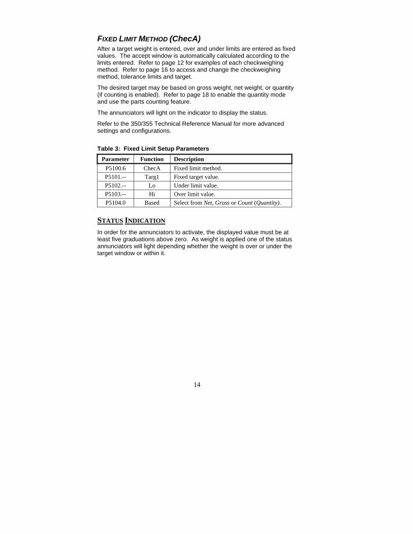
FIXED LIMIT METHOD (ChecA) After a target weight is entered, over and under limits are entered as fixed values. The accept window is automatically calculated according to the limits entered. Refer to page 12 for examples of each checkweighing method. Refer to page 16 to access and change the checkweighing method, tolerance limits and target.
The desired target may be based on gross weight, net weight, or quantity (if counting is enabled). Refer to page 18 to enable the quantity mode and use the parts counting feature.
The annunciators will light on the indicator to display the status.
Refer to the 350/355 Technical Reference Manual for more advanced settings and configurations.
Table 3: Fixed Limit Setup Parameters Parameter Function Description
P5100.6 ChecA Fixed limit method. P5101.-- Targ1 Fixed target value. P5102.-- Lo Under limit value. P5103.-- Hi Over limit value. P5104.0 Based Select from Net, Gross or Count (Quantity).
STATUS INDICATION In order for the annunciators to activate, the displayed value must be at least five graduations above zero. As weight is applied one of the status annunciators will light depending whether the weight is over or under the target window or within it.
15
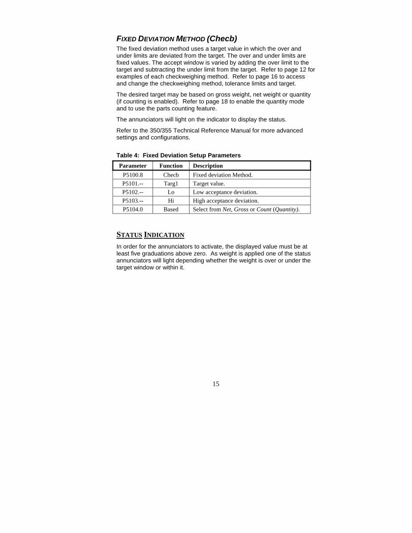
FIXED DEVIATION METHOD (Checb) The fixed deviation method uses a target value in which the over and under limits are deviated from the target. The over and under limits are fixed values. The accept window is varied by adding the over limit to the target and subtracting the under limit from the target. Refer to page 12 for examples of each checkweighing method. Refer to page 16 to access and change the checkweighing method, tolerance limits and target.
The desired target may be based on gross weight, net weight or quantity (if counting is enabled). Refer to page 18 to enable the quantity mode and to use the parts counting feature.
The annunciators will light on the indicator to display the status.
Refer to the 350/355 Technical Reference Manual for more advanced settings and configurations.
Table 4: Fixed Deviation Setup Parameters Parameter Function Description
P5100.8 Checb Fixed deviation Method. P5101.-- Targ1 Target value. P5102.-- Lo Low acceptance deviation. P5103.-- Hi High acceptance deviation. P5104.0 Based Select from Net, Gross or Count (Quantity).
STATUS INDICATION In order for the annunciators to activate, the displayed value must be at least five graduations above zero. As weight is applied one of the status annunciators will light depending whether the weight is over or under the target window or within it.
16
Setup
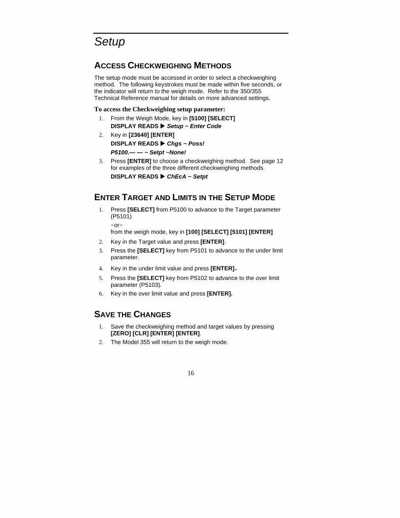
ACCESS CHECKWEIGHING METHODS The setup mode must be accessed in order to select a checkweighing method. The following keystrokes must be made within five seconds, or the indicator will return to the weigh mode. Refer to the 350/355 Technical Reference manual for details on more advanced settings.
To access the Checkweighing setup parameter: 1. From the Weigh Mode, key in [5100] [SELECT]
DISPLAY READS Setup ~ Enter Code 2. Key in [23640] [ENTER]
DISPLAY READS Chgs ~ Poss! P5100.— — ~ Setpt ~None!
3. Press [ENTER] to choose a checkweighing method. See page 12 for examples of the three different checkweighing methods. DISPLAY READS ChEcA ~ Setpt
ENTER TARGET AND LIMITS IN THE SETUP MODE 1. Press [SELECT] from P5100 to advance to the Target parameter
(P5101) ~or~ from the weigh mode, key in [100] [SELECT] [5101] [ENTER]
2. Key in the Target value and press [ENTER]. 3. Press the [SELECT] key from P5101 to advance to the under limit
parameter.
4. Key in the under limit value and press [ENTER]. 5. Press the [SELECT] key from P5102 to advance to the over limit
parameter (P5103). 6. Key in the over limit value and press [ENTER].
SAVE THE CHANGES 1. Save the checkweighing method and target values by pressing
[ZERO] [CLR] [ENTER] [ENTER]. 2. The Model 355 will return to the weigh mode.

17
ENTER TARGET VALUE AND LIMITS FROM THE WEIGH MODE A target value may be entered in one of two ways. Through the setup mode or weigh mode.
From the setup mode refer to Enter Target and Limits in the setup mode on page 16.
From the weigh mode:
3. Press [TARGET] to view the current target. DISPLAY READS Targ1 ~ 0.00 4. Key in the new target value and press [ENTER]. Example [10]
[ENTER] DISPLAY READS Targ1 ~ 10.00 5. Press [ENTER] to access the under tolerance parameter. This
parameter does not have to be changed. Go to step 5 to change the under tolerance or press [SELECT] to accept the value and go to the weigh mode or press [ENTER] to view the over tolerance, go to step 6.
DISPLAY READS Lo ~ 2 6. Set the under tolerance to a specific value. For example press [1]
[ENTER] to set the under tolerance to 1. DISPLAY READS Lo ~ 1 7. Press [ENTER] to access the over tolerance setting. This
parameter does not have to be changed. Go to step 7 to change the over tolerance or press [SELECT] to accept the value and to go to the weigh mode.
DISPLAY READS Hi ~ 3 8. Set the over tolerance to a specific value. For example press [2]
[ENTER] to set the over tolerance to 2. DISPLAY READS Hi ~ 2 9. Press [SELECT] to display the current gross weight.
DISPLAY READS 15.12
Parts Counting The counting parameter must be enabled before the quantity mode is available. Refer to the following instructions to enable the count mode and save the change.

18
ENABLE COUNT MODE (QUANTITY) To access the Counting setup parameter:
1. From the Weigh Mode, key in [179] [SELECT] DISPLAY READS Setup ~ Enter Code
2. Key in [23640] [ENTER] DISPLAY READS Chgs ~ Poss! P179.— — ~ Count ~diSbl
3. Press [ENTER] to enable the count (quantity) mode. See the instructions below for using the counting feature. DISPLAY READS Count ~Enbld
SAVE THE CHANGES 1. To save the change, press [ZERO] [CLR] [ENTER] [ENTER]. 2. The Model 355 will return to the weigh mode.
COUNTING METHODS
To sample using selectable fixed counts: 1. Press [SELECT] until the QTY annunciator is lit. 2. Press [TARE] to perform an auto-tare. The scale prompts to add 10
pieces. DISPLAY READS Add ~ 10
3. Press [UNITS] to toggle sample amounts between 5, 10, 20, 50 and 100. DISPLAY READS Add ~ 20
4. Add the pieces to be sampled to the scale and press [ENTER] to sample and display the current quantity.
DISPLAY READS 20
To sample using variable counts: 1. Press [SELECT] until the QTY annunciator is lit. 2. Press [TARE] to perform an auto-tare. The scale prompts to add 10
pieces. DISPLAY READS Add ~ 10
3. Add the pieces to be sampled to the scale, key in the number of pieces added to the scale (example: 36), then press [ENTER] to sample the pieces and display the current quantity. DISPLAY READS Add ~ 36

19
CHAPTER 4: MODEL 465 SETUP
The Model 465 CheckWeigher provides flexibility along with a brightly lit vacuum fluorescent display.
DISPLAY The Model 465 display is a 6-digit, 7-segment VF display (0.75”; 19mm high digits) with 2X5 prompting area.
KEYPAD The 465 uses a 22-key front panel keypad. The Model 465 keypad performs different functions in the weigh mode, the setup mode, and the calibration mode. The integrated [TARGET] and number keys make entering a target or over/under value easy.
PRINT TARGET
ID
UNITS
ENTER
TARE
SCALESELECTZERO SELECTF1
YES
321
- # :,%
PQRS
7
4GHI
CLR0 NO
8TUV WXYZ
9
5JKL
6MNO
ABC DEF
ALPHAGSE 465

20
Checkweighing Method Choices
FIXED LIMIT The Fixed Limit method uses the Over and Under tolerances as an accept window. The accept window is the value between the limits set. The over and under limits are entered as absolute values.
The Fixed Limit method is based on the gross weight, net weight, or count mode.
ACCEPT WINDOW The Accept window is between the Over and Under targets
Example: Low limit = 5.49, High Limit= 5.99
Accept Window = 5.49 to 5.99
% OF TARG The Percentage of Target method deviates the over and under limits from the target value in terms of a percentage. After a target weight is entered, Over and Under tolerances are entered as a percentage of the target. The Over and Under tolerance values are automatically calculated according to the percentages entered.
The Percentage of Target method is based on the gross weight, net weight, or count mode.
ACCEPT WINDOW The Accept window is between the Over and Under targets
Example: Target = 5.74, Over target = 2%, Under target = 2%
High Limit: 5.74 + 2% = 5.85 Low Limit: 5.74 – 2% = 5.63
Accept Window = 5.63 to 5.85

21
FIXED DEV. The Fixed Deviation method uses a target value in which the over and under tolerances are deviated from the target. The Over and Under tolerances are fixed values. The accept window is varied by adding the Over tolerance to the target and subtracting the Under tolerance from the target.
The Fixed Deviation method is based on the gross weight, net weight, or count mode.
ACCEPT WINDOW The Accept window is between the Over and Under targets
Example: Target = 5.74, Over target = 0.5, Under target = 0.25
High Limit: 5.74 + 0.5 = 6.24 Low Limit: 5.74 - 0.25 = 5.49
Accept Window = 5.49 to 6.24 Under = Below 5.49 Over = Above 6.24
Status Indication The display will show the status with one of the following:
Over
Good
Under
22
Operating Mode Choices
NET MODE The net weight can be used to determine the weight of product in a container if the tare weight of the container has been established.
NET = GROSS - TARE
The displayed net weight is rounded to the nearest display division size while the value stored in the Net parameter remains as the internally calculated net weight.
GROSS MODE The gross weight parameter represents the total live weight on the scale since the last time a zero reference was established by pressing [ZERO] or through zero tracking. The gross weight is calculated internally and its value cannot be changed by any other means.
When displaying the gross weight, the internally calculated value is rounded to the nearest display division size. However, the gross weight stored in Gross parameter remains the same as the internally calculated value, a value of greater precision than the displayed value.
COUNT MODE The quantity parameter is an active weight parameter that represents a number of pieces on the scale. The quantity is calculated by dividing the net weight by the average piece weight (APW):
QUANTITY = NET / APW
The quantity can be established by two methods:
• Performing a piece sample. • Assigning a value to the average piece weight parameter.
If an APW has not been established, the prompt “Must Sampl” will be displayed when attempting to access the quantity mode. Press [ENTER] to tare the scale and begin the sampling routine. Add pieces to be counted to the scale and press [ENTER].
When the display shows a quantity greater than zero (0), you can change the quantity by keying in the correct value and pressing [ENTER]. The APW will be recalculated accordingly and the newly entered quantity will be displayed.

23
Setup (F1) Press [F1] from the weigh mode to change the checkweighing method and/or the operating mode.
By default, Fixed Deviation is enabled using the Net mode. Follow the instructions below to set the checkweighing method, operating mode, target and limits.
VIEW METHOD AND OPERATING MODE Press [F1] from the weigh mode. The operating mode will be displayed on the left hand portion of the display and the checkweigh method will be shown on the right hand side of the display.
If no keys are pressed, the display will return to the weigh mode after 2.5 seconds.
SET METHOD AND OPERATING MODE Set the checkweighing method and operating mode that will be used.
CHECKWEIGH METHOD Press [F1] from the weigh mode. The checkweighing method will be displayed on the right hand side.
Press [F1] again to change the checkweighing method (see page 20 for details on the three different methods offered). If the current method is acceptable do not press any keys, the display will return to the weigh mode after 2.5 seconds.
OPERATING MODE Press [F1] from the weigh mode. The operating mode will be displayed on the left hand portion of the display
Press [TARGET] to change the operating mode (see page 22 for details on the three different operating modes offered). If the current mode is acceptable do not press any keys, the display will return to the weigh mode after 2.5 seconds.

24
Set Target and Limits (TARGET) A target value can either be entered as a value or accepted with the target weight on the scale.
Pressing [F1] while entering a target or limit value will enter a negative (-) sign.
ENTER A KNOWN TARGET VALUE Enter the desired target value and press [ENTER].
The lower limit or percent will be displayed next. If the lower value is acceptable press [ENTER], otherwise key in the desired value and press [ENTER].
The upper limit or percent will be displayed next. If the upper value is acceptable press [ENTER], otherwise key in the desired value and press [ENTER]. The display will return to the weight mode.
NOTE: The FIXED LIMIT method of checkweighing is not based on a target value so only the lower and upper limits or percent will be displayed.
ACCEPT A WEIGHT AS THE TARGET VALUE (FAST TARGET) Add the weight of the desired target value to the scale and press [TARGET]. The target will be updated to the weight applied.
The lower and upper limits or percent will not be automatically updated. To change the limits or percent, return the weight to zero and press [TARGET]. Press [ENTER] to access the limits.
The lower limit or percent will be displayed next. If the lower value is acceptable press [ENTER], otherwise key in the desired value and press [ENTER].
The upper limit or percent will be displayed next. If the upper value is acceptable press [ENTER], otherwise key in the desired value and press [ENTER]. The display will return to the weight mode.
NOTE: The FIXED LIMIT method of checkweighing is not based on a target and the weight applied will not be accepted as a target. Instead, the lower limit or percentage will be displayed.
25
Set a Password Code In order to prevent accidental configuration changes, it may be necessary to assign a password code. If a password code is enabled, the [F1], [TARGET], and [ID] will be protected. The password code may be strictly numeric or consist of alpha and numeric characters.
The password code should be allocated and kept by an administrator.
How to set a password code: 1. From the weigh mode key in [80.10] [SELECT]. If a password
code already exists it will be displayed, otherwise the display will be blank.
2. Key in the desired pass code and press [ENTER].
Accessing a password protected parameter: 1. Press the key corresponding with the desired function (F1,
TARGET or ID). 2. The display will prompt “Enter Code”. Key in the password code
and press [ENTER]. If the wrong code was entered “Wrong Code” will be displayed for 1 second and the display will return to weigh mode.
Product ID Up to 20 different products can be configured with exclusive settings.
A new product ID is entered from the weigh mode and a unique product name can also be entered. Only five characters of the name will be displayed.
QUICK RECALL BY ID NUMBER: Key in the desired product ID# 1 - 20 and press [ID]. The product number will be shown in the large portion of the display and the name (if the product was named) in the small section of the display will remain for 1.5 seconds. The target and limits will also be recalled.
If a number larger than 20 is entered “Not Found” will be display briefly

26
RECALL BY PRODUCT ID OR PRODUCT NAME: Press the [ID] key and the current ID and product number will be shown.
Recall by ID#: Key in the desired product ID# 1 – 20 and press [ENTER].
Recall by Product Name: Key in the name of the desired product and press [ENTER]. If the name entered is found, it will recall that product from the database. If not found, the name entered will be assigned to the current product ID.

27
CHAPTER 5: MODEL 562 SETUP
The Model 562 CheckWeigher provides flexibility along with an easy to read graphic display. Two different choices are offered for displaying the UNDER, ACCEPT AND OVER status.
Display The Model 562 comes standard with an 8 line x 40 character graphic display. The display provides easy to read operator interface with large Over, Accept and Under annunciators.
Keypad The Model 562 Checkweigher uses a 22-key front panel keypad. The Model 562 keypad performs different functions in the weigh mode, the setup mode, and the calibration mode. The integrated function keys and number keys make entering a target or over/under value easy.
UNITSPRINT
ID
STOP
ENTER
TARE
SELECTSCALEZERO
STARTSELECT
F3
F2
F1
654TUV
87- # :,%
0
PQRS
9
CLR
WXYZ
ABC
JKLGHI
1 2 3MNO
DEF
NOYESALPHA
GSE 560
28
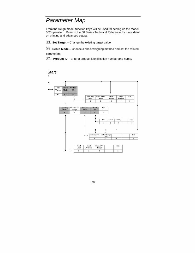
Parameter Map From the weigh mode, function keys will be used for setting up the Model 562 operation. Refer to the 60 Series Technical Reference for more detail on printing and advanced setups.
Set Target – Change the existing target value.
Setup Mode – Choose a checkweighing method and set the related
parameters.
Product ID – Enter a product identification number and name.
Set Target
Setup Mode
Product ID
F1 F2 F3
Fixed Limit
Fixed Deviation
Percent Of Target
Exit
1 2 3 5
Add New Product
Add/ChangeName
Setup Values
Delete Product
Exit
1 2 3 4 5
Operating Mode
Over/Under Target
Display Style
Based On
Exit
1 2 3 4 5
<<Accept>>
Under/AcceptOver
Exit
1 2 3 5
Net Gross Count Exit
1 2 3 5
Start

29
Set Target (F1) A target value can either be entered as a value or accepted with the target weight on the scale.
ENTER A KNOWN TARGET VALUE Make sure the displayed weight reads zero and press [F1]. Enter the desired target value and press [ENTER].
ACCEPT A WEIGHT AS THE TARGET VALUE Place the desired target weight on the scale and press [F1]. The target and over/under limits will be automatically adjusted. If the over/under limits need to be reset, see page 37.

30
Setup Mode (F2) Three different modes of operation are offered with the Model 562 CheckWeigher (Fixed Deviation, Fixed Limit and Percentage of Target).
Press [F2] from the weigh mode to access the setup mode for choosing a checkweighing method and customizing that method.
By default, the Fixed Deviation method is enabled. Follow the instructions below to set the checkweighing method, target and limits.
To set which checkweighing method that will be used, press [1] to access the operating mode setup.
OPERATING MODE (1)
1) FIXED DEVIATION Press [1] to select the Fixed Deviation checkweighing method.
The Fixed Deviation method uses a target value in which the over and under tolerances are deviated from the target. The Over and Under tolerances are fixed values. The accept window is varied by adding the Over tolerance to the target and subtracting the Under tolerance from the target.
The Fixed Deviation method is based on the gross weight, net weight, or count mode.
After the Fixed Deviation method is chosen, the OVER/UNDER TARGET window will be displayed.
Key in the Under target and press [ENTER]. If the Under target value displayed is acceptable, press [ENTER] to move the cursor to the Over target.
Key in the Over target and press [ENTER]. If the Over target value displayed is acceptable, press [ENTER] to accept.
31
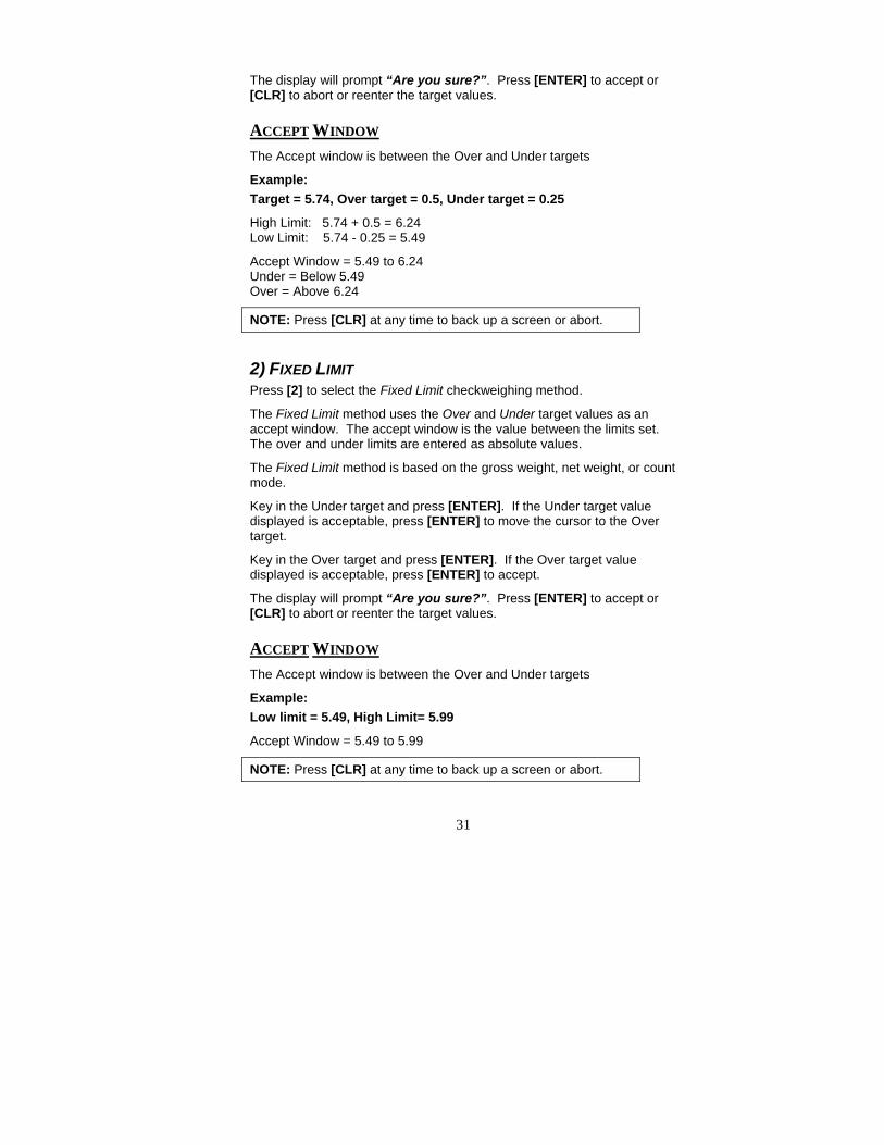
The display will prompt “Are you sure?”. Press [ENTER] to accept or [CLR] to abort or reenter the target values.
ACCEPT WINDOW The Accept window is between the Over and Under targets
Example: Target = 5.74, Over target = 0.5, Under target = 0.25
High Limit: 5.74 + 0.5 = 6.24 Low Limit: 5.74 - 0.25 = 5.49
Accept Window = 5.49 to 6.24 Under = Below 5.49 Over = Above 6.24
NOTE: Press [CLR] at any time to back up a screen or abort.
2) FIXED LIMIT Press [2] to select the Fixed Limit checkweighing method.
The Fixed Limit method uses the Over and Under target values as an accept window. The accept window is the value between the limits set. The over and under limits are entered as absolute values.
The Fixed Limit method is based on the gross weight, net weight, or count mode.
Key in the Under target and press [ENTER]. If the Under target value displayed is acceptable, press [ENTER] to move the cursor to the Over target.
Key in the Over target and press [ENTER]. If the Over target value displayed is acceptable, press [ENTER] to accept.
The display will prompt “Are you sure?”. Press [ENTER] to accept or [CLR] to abort or reenter the target values.
ACCEPT WINDOW The Accept window is between the Over and Under targets
Example: Low limit = 5.49, High Limit= 5.99
Accept Window = 5.49 to 5.99
NOTE: Press [CLR] at any time to back up a screen or abort.
32
3) PERCENT OF TARGET Press [3] to select the Percentage of Target checkweighing method.
The Percentage of Target method deviates the over and under limits from the target value in terms of a percentage. After a target weight is entered, Over and Under tolerances are entered as a percentage of the target. The Over and Under tolerance values are automatically calculated according to the percentages entered.
The Percentage of Target method is based on the gross weight, net weight, or count mode.
Key in the Under target and press [ENTER]. If the Under target value displayed is acceptable, press [ENTER] to move the cursor to the Over target.
Key in the Over target and press [ENTER]. If the Over target value displayed is acceptable, press [ENTER] to accept.
The display will prompt “Are you sure?”. Press [ENTER] to accept or [CLR] to abort or reenter the target values.
NOTE: Press [CLR] at any time to back up a screen or abort.
ACCEPT WINDOW The Accept window is between the Over and Under targets
Example: Target = 5.74, Over target = 2%, Under target = 2%
High Limit: 5.74 + 2% = 5.85 Low Limit: 5.74 – 2% = 5.63
Accept Window = 5.63 to 5.85
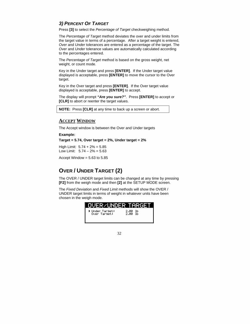
OVER / UNDER TARGET (2) The OVER / UNDER target limits can be changed at any time by pressing [F2] from the weigh mode and then [2] at the SETUP MODE screen.
The Fixed Deviation and Fixed Limit methods will show the OVER / UNDER target limits in terms of weight in whatever units have been chosen in the weigh mode.
33
The Percentage method will show the OVER / UNDER target limits in terms of a percent.
SET UNDER AND OVER TARGET LIMITS Set the Over / Under target limits by pressing [2].
Key in the Under target limit and press [ENTER]. If the Under target value displayed is acceptable, press [ENTER] to move the cursor to the Over target.
Key in the Over target limit and press [ENTER]. If the Over target value displayed is acceptable, press [ENTER] to accept.
The display will prompt “Are you sure?”. Press [ENTER] to accept or [CLR] to abort or reenter the target values.
NOTE: Press [CLR] at any time to back up a screen or abort.
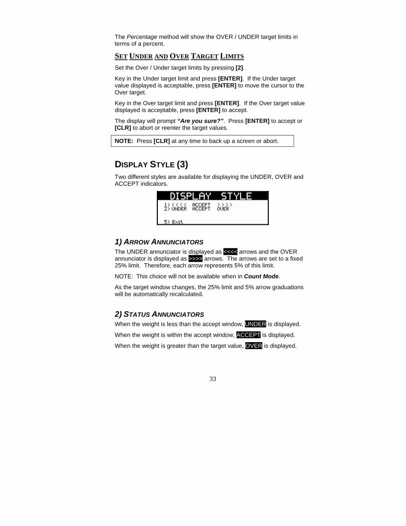
DISPLAY STYLE (3) Two different styles are available for displaying the UNDER, OVER and ACCEPT indicators.
1) ARROW ANNUNCIATORS The UNDER annunciator is displayed as <<<< arrows and the OVER annunciator is displayed as >>>> arrows. The arrows are set to a fixed 25% limit. Therefore, each arrow represents 5% of this limit.
NOTE: This choice will not be available when in Count Mode.
As the target window changes, the 25% limit and 5% arrow graduations will be automatically recalculated.
2) STATUS ANNUNCIATORS When the weight is less than the accept window, UNDER is displayed.
When the weight is within the accept window, ACCEPT is displayed.
When the weight is greater than the target value, OVER is displayed.
34
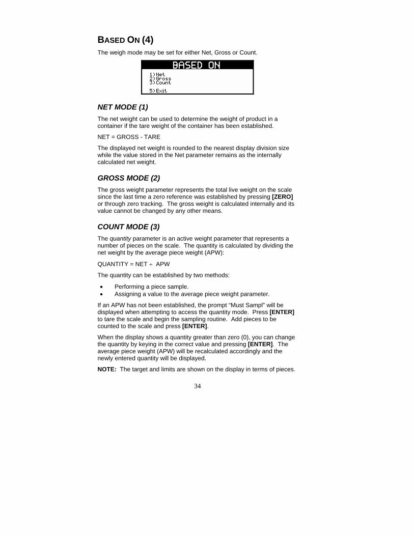
BASED ON (4) The weigh mode may be set for either Net, Gross or Count.
NET MODE (1) The net weight can be used to determine the weight of product in a container if the tare weight of the container has been established.
NET = GROSS - TARE
The displayed net weight is rounded to the nearest display division size while the value stored in the Net parameter remains as the internally calculated net weight.
GROSS MODE (2) The gross weight parameter represents the total live weight on the scale since the last time a zero reference was established by pressing [ZERO] or through zero tracking. The gross weight is calculated internally and its value cannot be changed by any other means.
COUNT MODE (3) The quantity parameter is an active weight parameter that represents a number of pieces on the scale. The quantity is calculated by dividing the net weight by the average piece weight (APW):
QUANTITY = NET ÷ APW
The quantity can be established by two methods:
• Performing a piece sample. • Assigning a value to the average piece weight parameter.
If an APW has not been established, the prompt “Must Sampl” will be displayed when attempting to access the quantity mode. Press [ENTER] to tare the scale and begin the sampling routine. Add pieces to be counted to the scale and press [ENTER].
When the display shows a quantity greater than zero (0), you can change the quantity by keying in the correct value and pressing [ENTER]. The average piece weight (APW) will be recalculated accordingly and the newly entered quantity will be displayed.
NOTE: The target and limits are shown on the display in terms of pieces.

35
Product ID (F3) Up to 20 different products can be configured with unique settings.
A new product ID number can be entered from the weigh mode in two different ways.
From the weigh mode: 1. Key in the ID number and press [F3/ID]. “NOT FOUND ~ NEW
ID?” will be displayed if the ID number does not exist in the database.
2. Press [ENTER] to accept the new product ID number or [CLR] to abort the entry. The settings will be the same as the product that is currently accessed.
3. Configure the name and settings through the Product ID menu.
If the product ID was found in the database, it will be selected.
Press the [SELECT] key from the weigh mode to view the currently selected product ID number and name.
From the Product ID menu:
1) ADD NEW PRODUCT Press [1] to access the Add New Product screen. Key in the product identification number and press [ENTER]. The display will prompt “Are you sure?”. Press [ENTER] to accept or [CLR] to abort or reenter the Product ID.
After the Product ID is entered the screen will return to the Product ID screen. At this point the product ID can be named or set values specific to the product ID.
2) ADD / CHANGE NAME Press [2] to access the Add/Change Name screen. Key in the product name associated with the product identification number entered in the previous step. The numeric keys are also used for alpha characters.
NOTE: This option will not be displayed if no product ID number was entered previously.
36
Keys [2] – [9] have uppercase and lowercase alphabetic characters assigned to them. The [ . ] key scrolls through the remaining characters. The [0] is used for inserting a space. Press the [CLR] + [0] keys simultaneously to backspace one character.
To enter characters, press the corresponding number key on the keypad. The first character in the sequence will appear first. Continue pressing the key before the timeout occurs to scroll through the characters for that key.
3) SETUP VALUES Press [3] to access the Setup Values screen. When the setup values screen is chosen, the display goes to the SETUP MODE screen (refer to page 30).
The checkweighing method, targets and display style settings are saved to the product identification number and are unique to that number.
4) DELETE PRODUCT To delete a product ID it must first be selected. Do so by keying in the product ID number and press [F3 / ID] while in the weigh mode. Press [F3 / ID] and then [4] to access the Delete Product screen. The display will prompt “Are you sure?” and show the currently selected Product ID number and name. Press [ENTER] to accept or [CLR] to cancel deleting the Product ID.
ACCESS AN EXISTING PRODUCT ID After a product ID has been saved it is possible to access that ID and its’ settings. From the weigh mode key in the number and press [F3 / ID].
To view which product ID number is currently being used press [SELECT] from the weigh mode. The ID number and name will be displayed. Press [SELECT] again to return to the target and limit view.
37
Set Target or Under/Over Limits SET TARGET Set a target by applying the target weight and press [F1]. ~ OR ~ The target can also be set with the weight at zero and press [F1]. Key in the desired target weight and press [ENTER].
SET UNDER AND OVER LIMITS Set the Over / Under targets by pressing [2] from the SETUP MODE screen.
Set a Password Code In order to prevent accidental configuration changes, it may be necessary to assign a password code. If a password code is enabled, the [F1], [F2], and [F3/ID] will be protected. The password code may be strictly numeric or consist of alpha and numeric characters.
The password code should be allocated and kept by an administrator.
How to set a password code: 1. From the weigh mode key in [80.10] [SELECT]. If a password
code already exists it will be displayed, otherwise the display will be blank.
2. Key in the desired pass code and press [ENTER].
Accessing a password protected parameter: 1. Press the key corresponding with the desired function (F1, F2 or
F3/ID). 2. The display will prompt “Enter Code”. Key in the password code
and press [ENTER].
If the wrong code was entered “Wrong Code” will be displayed for 1 second and the display will return to weigh mode.

39
CHAPTER 6: CALIBRATION
Model 355 Checkweigher
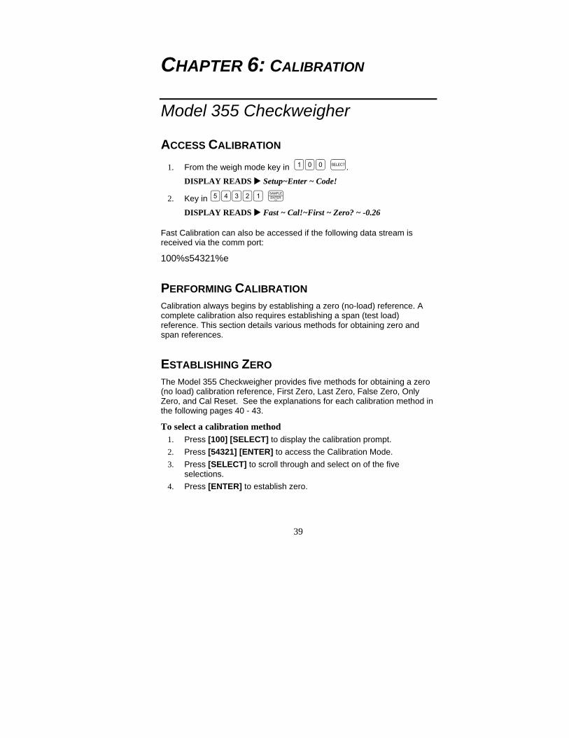
ACCESS CALIBRATION 1. From the weigh mode key in . DISPLAY READS Setup~Enter ~ Code!
2. Key in
DISPLAY READS Fast ~ Cal!~First ~ Zero? ~ -0.26
Fast Calibration can also be accessed if the following data stream is received via the comm port:
100%s54321%e
PERFORMING CALIBRATION Calibration always begins by establishing a zero (no-load) reference. A complete calibration also requires establishing a span (test load) reference. This section details various methods for obtaining zero and span references.
ESTABLISHING ZERO The Model 355 Checkweigher provides five methods for obtaining a zero (no load) calibration reference, First Zero, Last Zero, False Zero, Only Zero, and Cal Reset. See the explanations for each calibration method in the following pages 40 - 43.
To select a calibration method 1. Press [100] [SELECT] to display the calibration prompt. 2. Press [54321] [ENTER] to access the Calibration Mode. 3. Press [SELECT] to scroll through and select on of the five
selections. 4. Press [ENTER] to establish zero.

40
FIRST ZERO The most common zeroing procedure, First Zero is used to establish a new zero (no load) calibration reference before proceeding to span the Model 355 Checkweigher. Use this method for first-time calibration and complete recalibration.
First Zero Calibration Method Example 1. From the Weigh Mode key in [100] [SELECT]. DISPLAY READS Setup 2. Key in [54321] [ENTER].
DISPLAY READS Fast ~ Cal~First ~ Zero? ~ -0.26 3. Remove any load on the scale.
DISPLAY READS First ~ Zero? ~ -0.42 4. Press [ENTER] to establish zero.
DISPLAY READS 0.00 5. Pause for motion delay.
DISPLAY READS Enter ~ Load ~ 0.00 6. Place a 100lb test weight on scale.
DISPLAY READS Enter ~ Load ~ 99.66 7. Enter [100]. DISPLAY READS 100 8. Press [ENTER] to establish span.
DISPLAY READS 100.00 9. Pause for motion delay.
DISPLAY READS Cal ~ Good? ~ 100.00 10. Press [ENTER] to accept calibration.
DISPLAY READS Enter ~ =Stor 11. Press [ENTER] to save calibration.
DISPLAY READS Enter ~ =End 12. Press [ENTER] to exit calibration.
DISPLAY READS 100.00 13. Remove the calibration weight.
DISPLAY READS 0.00
LAST ZERO The Last Zero procedure allows recalibration of the weighing device using an existing test load. This is especially beneficial when checking high capacity applications such as tank weighing to minimize the task of placing and removing test weights.

41
Establish gross zero before entering setup or calibration!
Last Zero Calibration With Weight Already Applied Example
1. Remove any load on the scale. DISPLAY READS 10.
2. Press [ZERO] to zero the scale. DISPLAY READS 00.
3. Apply a 10000 lb test weight to verify calibration. DISPLAY READS 9970.
4. Press [100] [SELECT]. DISPLAY READS Setup
5. Press [54321] [ENTER]. DISPLAY READS Fast ~ Cal~First ~ Zero? ~ 9930.
6. Press [SELECT]. DISPLAY READS Last ~ Zero? ~9930.
7. Press [ENTER] to use last zero. DISPLAY READS Enter ~ Load? ~ 9970.
8. Enter [10000]. DISPLAY READS 10000
9. Press [ENTER] to establish span. DISPLAY READS 10000.
10. Pause for motion delay. DISPLAY READS Cal ~ Good? ~ 10000.
11. Press [ENTER] to accept calibration. DISPLAY READS Enter ~ =Stor
12. Press [ENTER] to save calibration. DISPLAY READS Enter ~ =End
13. Press [ENTER] to exit calibration. DISPLAY READS 10000.
14. Remove the calibration weight. DISPLAY READS 00.
FALSE ZERO False Zero calibrates the Model 355 Checkweigher without removing the current gross weight. This is particularly useful in tank weighing

42
applications where it may be both time consuming and costly to completely empty the tank. This operation is achieved by establishing a false (temporary zero) zero reference. Test weights may then be added to verify calibration. The zero reference determined during the last calibration is not affected.
False Zero Calibration Without Removing Existing Load Example 1. Press [100] [SELECT].
DISPLAY READS Setup 2. Press [54321] [ENTER].
DISPLAY READS Fast ~ Cal~First ~ Zero? ~ 5075. 3. Press [SELECT] [SELECT].
DISPLAY READS False ~ Zero? ~5075. 4. Press [ENTER] to establish false (temporary) zero.
DISPLAY READS Units ~ =lb 5. Pause to display calibration units.
DISPLAY READS Enter ~ Load? ~ 00. 6. Place a 2500lb test weight on scale.
DISPLAY READS Enter ~ Load? ~ 2510. 7. Enter [2500].
DISPLAY READS 2500 8. Press [ENTER] to establish span.
DISPLAY READS 2500. 9. Pause for motion delay.
DISPLAY READS Cal ~ Good? ~ 2500. 10. Press [ENTER] to accept calibration.
DISPLAY READS Enter ~ =Stor 11. Press [ENTER] to save calibration.
DISPLAY READS Enter ~ =End 12. Press [ENTER] to exit calibration.
DISPLAY READS 5055. 13. Remove the calibration weight.
DISPLAY READS 00.
ONLY ZERO Only Zero is used to establish a new calibration zero without affecting the span. This is useful for correcting changes to the scale’s dead load, for example adding safety rails to a truck scale platform.
43
Only Zero Calibration Example 1. From the Weigh Mode, press [100] [SELECT].
DISPLAY READS Setup 2. Press [54321] [ENTER].
DISPLAY READS Fast ~ Cal~First ~ Zero? ~2640. 3. Press [SELECT] [SELECT] [SELECT].
DISPLAY READS Only ~ Zero? ~ 2640. 4. Remove any load on the scale.
DISPLAY READS Only ~ Zero? ~ 2620. 5. Press [ENTER] to establish zero.
DISPLAY READS 00. 6. Pause for motion delay.
DISPLAY READS Cal ~ Good? ~ 00. 7. Press [ENTER] to accept calibration.
DISPLAY READS Enter ~ =Stor 8. Press [ENTER] to save calibration.
DISPLAY READS Enter ~ =End 9. Press [ENTER] to exit calibration.
DISPLAY READS 00.
RESET CALIBRATION Cal Reset may be necessary when an over-load or under-load condition exists, preventing the completion of the calibration process. Calibration Reset adjusts the zero and gain factors of the A/D amplifier to factory default values for maximum sensitivity. After performing a calibration reset, a complete recalibration is required. The effects of a calibration reset do not take effect until the Model 355 Checkweigher recalibrated and calibration information has been saved.
If Code 02 (under-load) or Code 03 (over-load) is displayed during
calibration, press to perform a calibration reset.
Reset Calibration Gain Factors Example
1. Press [100] [SELECT]. DISPLAY READS Setup
2. Press [54321] [ENTER]. DISPLAY READS Fast ~ Cal~First ~ Zero? ~ xx.xx

44
3. Remove any load on the scale. DISPLAY READS First ~ Zero? ~ xx.xx
4. Press [ENTER] to establish zero. DISPLAY READS Enter ~ Load? ~ 0.00
5. Place a 100lb test weight on scale. DISPLAY READS Code03
6. Press [ZERO]. DISPLAY READS First ~ Zero? ~ -0.26
7. Remove any load on the scale. DISPLAY READS First ~ Zero? ~ -0.42
8. Press [ENTER] to establish zero. DISPLAY READS 0.00
9. Pause for motion delay. DISPLAY READS Enter ~ Load ~ 0.00
10. Place a 100lb test weight on scale. DISPLAY READS Enter ~ Load ~ xx.xx
11. Enter [100]. DISPLAY READS 100
12. Press [ENTER] to establish span. DISPLAY READS 100.00
13. Pause for motion delay. DISPLAY READS Cal ~ Good? ~ 100.00
14. Press [ENTER] to accept calibration. DISPLAY READS Enter ~ =Stor 15. Press [ENTER] to save calibration.
DISPLAY READS Enter ~ =End 16. Press [ENTER] to exit calibration.
DISPLAY READS 100.00 17. Remove the calibration weight.
DISPLAY READS 0.00
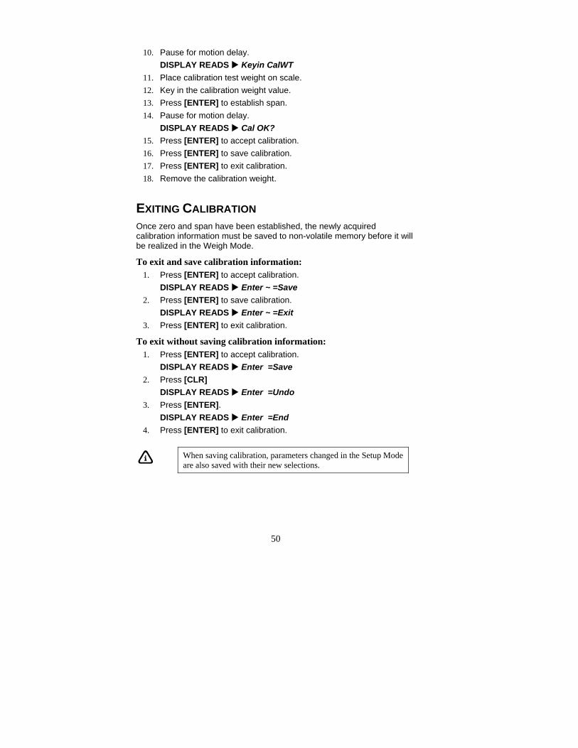
EXITING CALIBRATION Once zero and span have been established, the newly acquired calibration information must be saved to non-volatile memory before it will be realized in the Weigh Mode.
To exit and save calibration information: 1. Press [ENTER] to accept calibration.
DISPLAY READS Enter ~ =Stor

45
2. Press [ENTER] to save calibration. DISPLAY READS Enter ~ =End
3. Press [ENTER] to exit calibration. DISPLAY READS 100.00
To exit without saving calibration information: 4. Press [ENTER] to accept calibration.
DISPLAY READS Enter ~ =Stor 5. Press [CLR]
DISPLAY READS Enter ~ =Undo 6. Press [ENTER].
DISPLAY READS Enter ~ =End 7. Press [ENTER] to exit calibration.
DISPLAY READS 99.66
When saving calibration, parameters changed in the Setup Mode are also saved with their new selections.

46
Model 465 and 562 Checkweigher
PERFORMING CALIBRATION Calibration always begins by establishing a zero (no-load) reference. A complete calibration also requires establishing a span (test load) reference. This section details various methods for obtaining zero and span references.
ESTABLISHING ZERO The Model 465 AND 562 checkweighers provide five methods for obtaining a zero (no load) calibration reference, New Zero, Last Zero, Temp Zero, Only Zero, and Cal Reset.
To access calibration From the weigh mode press
1. Press [100] [SELECT] [5 4 3 2 1] [ID] [ENTER] DISPLAY READS New Zero?.
2. Press [SELECT] to scroll through and select on of the five selections.
3. Press [ENTER] to establish zero.
NEW ZERO The most common zeroing procedure, New Zero is used to establish a new zero (no load) calibration reference before proceeding to span the Model 465 and 562 Checkweighers. Use this method for first-time calibration and complete recalibration.
First Zero Calibration Method Example 1. From the Weigh Mode key in [100] [SELECT]. DISPLAY READS Setup 2. Key in [54321] [ID] [ENTER].
DISPLAY READS New Zero?. 3. Remove any load on the scale. 4. Press [ENTER] to establish zero.
DISPLAY READS 0.00 5. Pause for motion delay.
DISPLAY READS Keyin CalWt

47
6. Place a test weight on scale. For example 100 lb. DISPLAY READS Add CalWt ~ 99.66
7. Enter the value of the weight applied. Example [100]. DISPLAY READS 100 8. Press [ENTER] to establish span.
DISPLAY READS 100.00 9. Pause for motion delay.
DISPLAY READS Cal OK? ~ 100.00 10. Press [ENTER] to accept calibration. 11. Press [ENTER] to save calibration. 12. Press [ENTER] to exit calibration. 13. Remove the calibration weight.
LAST ZERO The Last Zero procedure allows recalibration of the weighing device using an existing test load. This is especially beneficial when checking high capacity applications such as tank weighing to minimize the task of placing and removing test weights.
1. Remove any load on the scale. 2. Press [ZERO] to establish zero.
DISPLAY READS 0.00 3. Place calibration test weight on scale. 4. Press [100] [SELECT].
DISPLAY READS Setup 5. Press [54321] [ENTER].
DISPLAY READS New Zero? 6. Press [SELECT].
DISPLAY READS Last Zero? 7. Key in the calibration weight value in terms of the default calibration
units and press [ENTER]. 8. Press [ENTER] to establish span.
DISPLAY READS 10000. 9. Pause for motion delay.
DISPLAY READS Cal OK? 10. Press [ENTER] to accept calibration. 11. Press [ENTER] to save calibration. 12. Press [ENTER] to exit calibration. 13. Remove the calibration weight.
48
TEMP ZERO? Temp Zero is used to recalibrate without establishing a new zero. In some applications you might want to perform a calibration without removing the currently applied load. This is particularly useful in tank weighing applications where it is both time-consuming and costly to drain the tank being weighed.
During the calibration procedure, at the Temp Zero? prompt you press [ENTER]. This action causes the controller to zero the displayed weight temporarily so additional weight can be added to assure system calibration. The zero determined during the previous calibration is not affected.
Temporary Zero Calibration Without Removing Existing Load Example
1. Press [100] [SELECT] to access the calibration mode. DISPLAY READS Setup
2. Press [54321] [ENTER]. DISPLAY READS New Zero?
3. Press [SELECT] [SELECT]. DISPLAY READS Temp Zero?
4. Press [ENTER] to establish temporary zero. The displayed value will zero out.
5. Apply the calibration weight. 6. Key in the value of the calibration weight and press [ENTER]. 7. Pause for motion delay.
DISPLAY READS Cal OK? 8. Press [ENTER] to accept calibration. 9. Press [ENTER] to save calibration. 10. Press [ENTER] to exit calibration. 11. Remove the calibration weight.
ONLY ZERO? Only Zero is used to establish a new calibration zero without affecting the span. This is useful for correcting changes to the scale’s dead load, for example in tank weighing applications where the re-zero parameter (P118) is set very low in order to prevent inadvertent re-zeroing. A build-up of sludge can be zeroed out in this manner.
Only Zero Calibration Example 1. Remove all weight from the scale 2. From the Weigh Mode, press [100] [SELECT].

49
DISPLAY READS Setup 3. Press [54321] [ENTER].
DISPLAY READS Fast ~ Cal~First ~ Zero? ~2640. 4. Press [SELECT] [SELECT] [SELECT].
DISPLAY READS Only Zero? 5. Press [ENTER] to establish zero. 6. Pause for motion delay.
DISPLAY READS Cal OK? 7. Press [ENTER] to accept calibration. 8. Press [ENTER] to save calibration. 9. Press [ENTER] to exit calibration.
CAL RESET Cal Reset may be necessary when an over-load or under-load condition exists, preventing the completion of the calibration process. Calibration Reset adjusts the zero and gain factors of the A/D amplifier to factory default values for maximum sensitivity. After performing a calibration reset, a complete recalibration is required. The effects of a calibration reset do not take effect until the indicator is recalibrated and calibration information has been saved.
Reset Calibration Gain Factors Example
1. Press [100] [SELECT]. DISPLAY READS Setup
2. Press [54321] [ENTER]. DISPLAY READS New Zero?
3. Press [SELECT] [SELECT] [SELECT] [SELECT]. DISPLAY READS Cal Reset
4. Press [ENTER] to select Cal Reset. DISPLAY READS New Zero?
5. Press [ENTER] to establish zero. 6. Place calibration test weight on scale.
DISPLAY READS Code03 7. Press [ZERO].
DISPLAY READS New Zero? 8. Remove any load on the scale. 9. Press [ENTER] to establish zero.
50
10. Pause for motion delay. DISPLAY READS Keyin CalWT
11. Place calibration test weight on scale. 12. Key in the calibration weight value. 13. Press [ENTER] to establish span. 14. Pause for motion delay.
DISPLAY READS Cal OK? 15. Press [ENTER] to accept calibration. 16. Press [ENTER] to save calibration. 17. Press [ENTER] to exit calibration. 18. Remove the calibration weight.
EXITING CALIBRATION Once zero and span have been established, the newly acquired calibration information must be saved to non-volatile memory before it will be realized in the Weigh Mode.
To exit and save calibration information: 1. Press [ENTER] to accept calibration.
DISPLAY READS Enter ~ =Save 2. Press [ENTER] to save calibration.
DISPLAY READS Enter ~ =Exit 3. Press [ENTER] to exit calibration.
To exit without saving calibration information: 1. Press [ENTER] to accept calibration.
DISPLAY READS Enter =Save 2. Press [CLR]
DISPLAY READS Enter =Undo 3. Press [ENTER].
DISPLAY READS Enter =End 4. Press [ENTER] to exit calibration.
When saving calibration, parameters changed in the Setup Mode are also saved with their new selections.

51
CHAPTER 7: ERROR CODES This chapter contains error messages and information parameters, as well as information on setup parameter selections and A/D Calibration.
Model 355 The Model 355 utilizes the following types of error messages: Operational Errors, Setup Mode Errors, Hardware Errors, Calibration Errors, Communication Errors, and Miscellaneous Errors.
OPERATIONAL ERRORS Code02 Under Load. Input signal is less than negative full
scale. Check load cell wiring. Code03 Over Load. Input signal is greater than positive full
scale. Use same checks as “under load” above. Funct ~ Disbl Attempted to perform a function disabled in the Setup
Mode. Code 04 The digits on the display have exceed the six digit
display capacity. Code 05 Zero attempted beyond that allowed by P118. Code 08 Input signal greatly exceeds the valid range. Check the
load cell connection. Tare ~ Error Negative tare attempted when disabled (P440 enabled). Tare ~ GT FS Tare value greater than full scale capacity. Delay Indicates that a motion delay is in effect (zero, tare,
etc.). Delay ~ Abort Acknowledges that a motion delayed function was
aborted. Print ~ Abort Acknowledges that a motion delayed print request was
aborted. Add ~ Load! If displayed after performing a count sample, this
message indicates that a larger sample size is required. Out of ~ Range Attempted to enter a value beyond the allowable range.
52
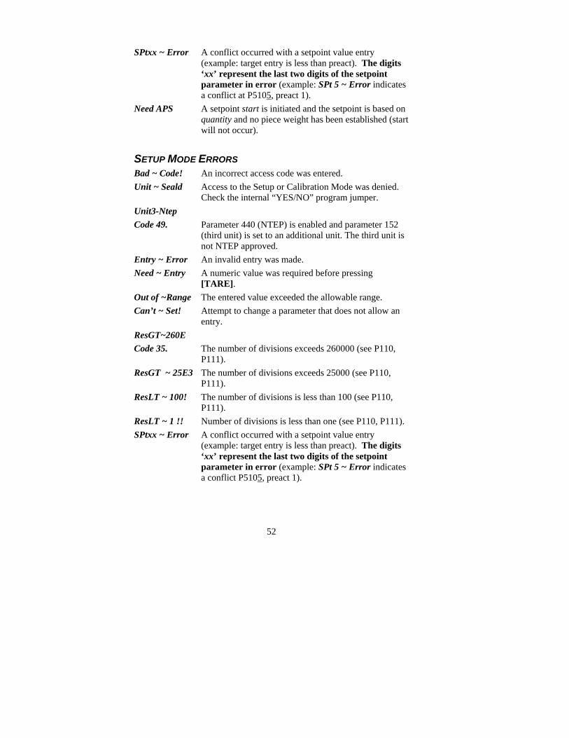
SPtxx ~ Error A conflict occurred with a setpoint value entry (example: target entry is less than preact). The digits ‘xx’ represent the last two digits of the setpoint parameter in error (example: SPt 5 ~ Error indicates a conflict at P5105, preact 1).
Need APS A setpoint start is initiated and the setpoint is based on quantity and no piece weight has been established (start will not occur).
SETUP MODE ERRORS Bad ~ Code! An incorrect access code was entered. Unit ~ Seald Access to the Setup or Calibration Mode was denied.
Check the internal “YES/NO” program jumper. Unit3-Ntep Code 49. Parameter 440 (NTEP) is enabled and parameter 152
(third unit) is set to an additional unit. The third unit is not NTEP approved.
Entry ~ Error An invalid entry was made. Need ~ Entry A numeric value was required before pressing
[TARE]. Out of ~Range The entered value exceeded the allowable range. Can’t ~ Set! Attempt to change a parameter that does not allow an
entry. ResGT~260E Code 35. The number of divisions exceeds 260000 (see P110,
P111). ResGT ~ 25E3 The number of divisions exceeds 25000 (see P110,
P111). ResLT ~ 100! The number of divisions is less than 100 (see P110,
P111). ResLT ~ 1 !! Number of divisions is less than one (see P110, P111). SPtxx ~ Error A conflict occurred with a setpoint value entry
(example: target entry is less than preact). The digits ‘xx’ represent the last two digits of the setpoint parameter in error (example: SPt 5 ~ Error indicates a conflict P5105, preact 1).

53
Prtcl ~ Error Existing protocol is invalid. The following are not allowed: P201 = 7 data bits, P202 = no parity, P203 = 1 stop bit P201 = 8 data bits, P202 = even parity, P203 = 2 stop bits P201 = 8 data bits, P202 = odd parity, P 203 = 2 stop bits
HARDWARE ERRORS Code00 A Flash memory problem detected during power-up (U2).
A-D ~ Bad! Or Code17
Problem with A/D chip detected. Disconnect any options installed and re-power the unit. Options are connected to the same serial lines as the A/D so they may prevent it from working properly.
Deflt ~ A-D Bad A/D calibration values. Recalibrate A/D (see 350/355 Technical Reference Manual).
Re- ~ Boot! FRAM data could not be read. Attempting power-up reset.
Chec ~ E2 FRAM data error (U4). Deflt ~ Setup An error occurred when reading setup data from the FRAM
during power-up. All parameters are set to factory default. Ch.XXXX A checksum error occurred during power-up. All
anunciators are lit. The FRAM integrity test failed or is improperly seated.
E2 ~ Full! The FRAM setup exceeds the memory capacity. NoSpc ~ Free!
The current setup exceeds the setup RAM capacity.
CALIBRATION ERRORS F.S. ~ TooHi The entered calibration weight will result in an over-
capacity condition at full scale. Verify that the full scale (P110) and calibration weight value are correct.
F.S. ~ TooLo The entered calibration weight will result in a full scale input signal less than the minimum allowed. Verify that the full scale (P110) and entered weight value are correct.
Add ~ Load! The calibration weight is less than 0.1% of capacity. More weight is required.

54
ReCal ~ ??? Repeat the cal. procedure for accuracy. This prompt appears when the calibration weight is less than 5% of capacity, or when the A/D coarse gain is adjusted.
Entry ~ Error An invalid entry was made.
COMMUNICATION ERRORS Par-Er The selected parity (P202) does not match that of the
connected device. Buf-Er The receive buffers capacity was exceeded. This
indicates a handshaking problem. Check P204 and verify proper communication port connections.
Bit-Er The stop bit of a received character did not occur when expected. Verify that protocol (P200 – P204) matches that of the connected device.
TrHold Data transmission is inhibited due to a deasserted
handshake. Press [CLR] to abort transmission. Check P204.
MISCELLANEOUS ERRORS T.X.YYYY If catastrophic errors occur in the software, a trap error
may occur and freeze the display with address information. (X = bank number and YYYY = the address of the trap error. Press any key five seconds after viewing message to reboot the unit).

55
Model 465 and 562
OPERATIONAL ERRORS MESSAGE Description
Code02 Under Load!
Input signal less than negative full scale. If this is due to excessive loading, reduce the load. Otherwise check the load cell connections. If a 4 wire load cell cable is being used, check that the sense jumpers are in place. Verify that the capacity selection P110 is correct. Use the information parameters, especially P61103 and P61104, to check the setup and input signal.
CoDE03 Over-Load!
Input signal is greater than positive full scale. Use same check as for underload.
CoDE04 #>
Dsply
Number to be displayed will not fit within 6 digits. This will not normally occur for the Gross, Net or Tare Weights but may result while displaying the accumulated totals if the amount exceeds 999,999. Either clear the totals or settle for only being able to transmit the totals.
CoDE05 Zero>
Max.!
An attempt was made to zero out more than allowed per P118 selection. Use the [TARE] key for subtracting off container weights or if large dead-load is always to be present, apply this dead-load during the No Load? prompt during calibration to permanently eliminate the offset.
CoDE06 Tare>
F.S.! Tare entry was greater than full scale. Most likely the entered tare value was incorrect.
CoDE07 Tare<
0!
Negative tare attempted, but not allowed per P162. For auto-tares, the GROSS Weight must be greater than zero unless P162 is changed to allow negative tares.
CoDE08 Check
Conn
The signal into the A/D is greater than +/- 2 times the expected full scale signal. For example if the full scale capacity at P110 is 100, then the error message will be displayed at +/- 208 taking into consideration the 4% overload. This error usually indicates a defective or incorrectly wired load cell.
56
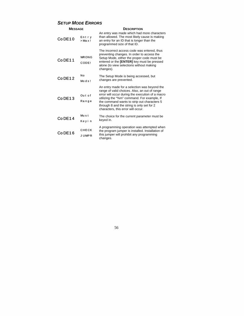
SETUP MODE ERRORS MESSAGE DESCRIPTION
CoDE10 Entry
>Max!
An entry was made which had more characters than allowed. The most likely cause is making an entry for an ID that is longer than the programmed size of that ID.
CoDE11 WRONG
CODE!
The incorrect access code was entered, thus preventing changes. In order to access the Setup Mode, either the proper code must be entered or the [ENTER] key must be pressed alone (to view selections without making changes).
CoDE12 No
Mods! The Setup Mode is being accessed, but changes are prevented.
CoDE13 Outof
Range
An entry made for a selection was beyond the range of valid choices. Also, an out of range error will occur during the execution of a macro utilizing the “%m” command. For example, If the command wants to strip out characters 5 through 8 and the string is only set for 2 characters, this error will occur.
CoDE14 Must
Keyin The choice for the current parameter must be keyed in.
CoDE16 CHECK
JUMPR
A programming operation was attempted when the program jumper is installed. Installation of this jumper will prohibit any programming changes.
57
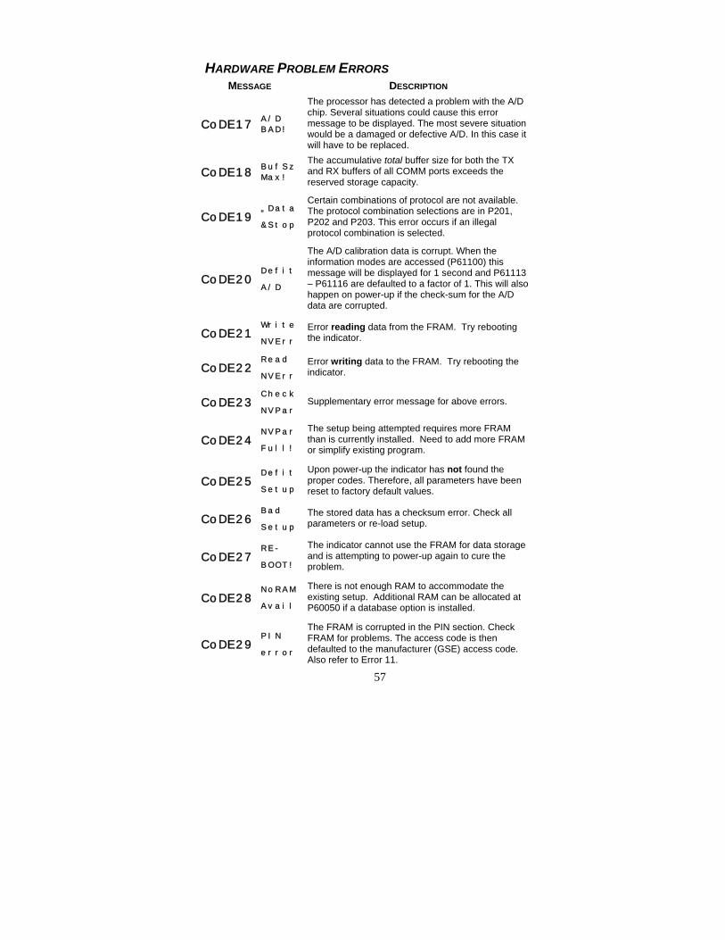
HARDWARE PROBLEM ERRORS MESSAGE DESCRIPTION
CoDE17 A/D
BAD!
The processor has detected a problem with the A/D chip. Several situations could cause this error message to be displayed. The most severe situation would be a damaged or defective A/D. In this case it will have to be replaced.
CoDE18 BufSz
Max!
The accumulative total buffer size for both the TX and RX buffers of all COMM ports exceeds the reserved storage capacity.
CoDE19 „Data
&Stop
Certain combinations of protocol are not available. The protocol combination selections are in P201, P202 and P203. This error occurs if an illegal protocol combination is selected.
CoDE20 Defit
A/D
The A/D calibration data is corrupt. When the information modes are accessed (P61100) this message will be displayed for 1 second and P61113 – P61116 are defaulted to a factor of 1. This will also happen on power-up if the check-sum for the A/D data are corrupted.
CoDE21 Write
NVErr Error reading data from the FRAM. Try rebooting the indicator.
CoDE22 Read
NVErr Error writing data to the FRAM. Try rebooting the indicator.
CoDE23 Check
NVPar Supplementary error message for above errors.
CoDE24 NVPar
Full!
The setup being attempted requires more FRAM than is currently installed. Need to add more FRAM or simplify existing program.
CoDE25 Defit
Setup
Upon power-up the indicator has not found the proper codes. Therefore, all parameters have been reset to factory default values.
CoDE26 Bad
Setup The stored data has a checksum error. Check all parameters or re-load setup.
CoDE27 RE-
BOOT!
The indicator cannot use the FRAM for data storage and is attempting to power-up again to cure the problem.
CoDE28 NoRAM
Avail
There is not enough RAM to accommodate the existing setup. Additional RAM can be allocated at P60050 if a database option is installed.
CoDE29 PIN
error
The FRAM is corrupted in the PIN section. Check FRAM for problems. The access code is then defaulted to the manufacturer (GSE) access code. Also refer to Error 11.

58
CALIBRATION ERRORS MESSAGE DESCRIPTION
CoDE30 F.S.>
MAX!
The entered calibration weight, together with the currently applied signal, indicates that the full scale signal will be greater than the allowed maximum of the indicator. Verify that correct entries have been made for the capacity, P110, and for the calibration weight.
CoDE31 F.S.<
.1mVv
The entered calibration weight, together with the currently applied signal, indicates that the full scale signal will be less than the allowed minimum of the indicator. Verify the proper entries for the capacity, P110, and for the calibration weight.
CoDE32 ADD
MORE! The applied weight during calibration was less than 0.1% of capacity. More weight than this is required. Refer to P61100 if this is incorrect.
CoDE33 ReCAL
Req'd
The just completed calibration is insufficient to guarantee accurate results due to either the cal weight being less than 5% of capacity or this was the first calibration of this platform to this indicator and, therefore, the coarse gain was adjusted by the indicator.
CoDE34 RES>
25K!
The current combination of capacity P110 and increment P111 result in a resolution greater than 25,000 graduations. This is simply a warning in case this was not intended.
CoDE35 RES>
100K!
The current combination of capacity P110 and increment P111 result in a resolution greater than 100,000 graduations. This is not allowed and the indicator will jump back into the setup mode to parameter P110. The settings will be verified after any key is pressed.
CoDE36 RES<
100!
The current combination of capacity P110 and increment P111 result in a resolution less than 100 graduations. This is simply a warning in case this was not intended.
CoDE37 RES<
1!!
The current combination of capacity P110 and increment P111 result in a resolution less than 1 graduation (for example, the increment is greater than capacity). This is not allowed and as soon as any key is pressed the indicator will jump back into the Setup Mode to parameter P110 to verify the settings.
CoDE38 Range
Error
In the multi-range setup, the low range exceeds the full scale capacity, or the middle range is less than the low range. Pressing any key will automatically select the parameter and allow it to be corrected.
CoDE39 „A/D˜
Cal
The A/D calibration values for one of the scales (shown as an inverse digit) have not been entered. Refer to Restoring A/D Calibration Values in the 60 Series Technical Reference Manual.

59
GENERAL ERRORS
MESSAGE DESCRIPTION
CoDE42 Check
Setup
A sample operation was performed with a sample size of “0” at parameter P34. The sample size must be > 0.
CoDE43 dbNOT
SETUP
An attempt to access an undefined database occurred. Make sure the intended database is configured beginning at P699. This error could also indicate that the database option has not yet been initialized at P65010.
CoDE48 E2Typ
Error
Both FRAM and standard EERPOM are installed in U27 & U28. Memory types cannot be intermixed. Power down and install one or two FRAM chips or one or two EEPROM chips and power up.
CoDE51 Too
Small
The sample placed on the platform is too small to accurately compute the piece weight. Increase the sample size.
CoDE52 Can't
Count
There is an insufficient quantity on the platform to perform an accurate count. Add more pieces.
CoDE53 Accy<
Req'D
The accuracy is less than required. The accuracy requirements specified at P183 has not been achieved. Increase the sample size.
CoDE54 Scale
Disbl
An attempt to select a disabled scale was made. Make sure the intended scale is enabled and properly configured beginning at P108.
CoDE56 dbNOTINIT
The database option has not initialized at 65010. This should not happen unless the indicator is powered down in the middle of a optional RAM test.
CoDE57 dbOpt Error
The FRAM database is corrupt (valid signature, invalid checksum). Contact GSE.
CoDE58 NewDb Opt'n
Database format has changed. This is most likely the result of upgrading to a new FLASH with a new database definition.
CoDE60 New
FLASH
A new FLASH file has been uploaded via the ReFlash or BDM flash utilities in order to upgrade the firmware. Press any key to acknowledge. Initialize database at P65010.
CoDE61 Need
Code
The setup mode access code has not been entered prior to attempting to change the configuration of a setup parameter. Key in the access code (i.e. 100 [SELECT] 23640 [ID] [ENTER] ).

60
MESSAGE DESCRIPTION
CoDE62 Comm#
Error
An entry error occurred at the “EnterCOMM#” prompt. This message appears during a setup download (P64000, P64001), database download, database print, etc. if the COMM port number was omitted or invalid.
CoDE71 TxNot
Exist
The specified custom transmit does not exist. An invalid custom transmit was entered at the “Which Tx#?” prompt or incorrectly specified with a %Q macro command. Make sure the intended custom transmit is configured beginning at P989.
CoDE72 ConTx
>Max! The maximum number of continuous transmits have been exceeded (16 for the 562 controller; 4 for the 465 indicator).
CoDE73 TxNot
Cont
A request was made to disable a continuous custom transmit using the D%Q command for a transmit that was not currently being continuously transmitted.
CoDE74 TxRat
>Max! A request was made to set the continuous transmit interval larger than the maximum value using the I%Q macro command.
CoDE75 Tx is
Cont.
A request was made to enable a continuous custom transmit using the C%Q command for a transmit that was currently being continuously transmitted.

61
SETUP ERRORS MESSAGE DESCRIPTION
Code92 „Stpt
Setup
A parameter entry is required for a setpoint’s Activation Limit, Deactivation Limit, or Compare parameter. Pressing any key will automatically select the offending parameter and allow you to correct it.
CoDE95 SyErrNvRam
The FRAM size is too small to allocate the database requested. Add additional FRAM to U28 on the Model 562 only.
CoDE95 SyErrHSR00
An error occurred at startup or during operation. Contact GSE.
CoDE95 SyErrTyp04
An error occurred at startup. Contact GSE.
Code96 EraseBoot!
An attempt was made to enter an indicator serial number or board serial number with the flash already programmed.
CoDE99 Can't
Set!
An attempt to enter a value for a parameter which is not field changeable, such as the serial numbers or the audit trail counter results in this message.
P___ InvldMode!
An attempt was made to access a non-existent parameter. Key in a valid parameter and press [SELECT], or press only [SELECT] or [SCALE SELECT] to proceed to the nearest valid parameter.
Mode <100!
An attempt was made to access a weigh mode parameter from within the setup mode. Valid setup mode parameters contain three or more digits. Key in a number > 100.
Press Enter
The [SELECT] key was pressed at a “pick instance” prompt. You must press [ENTER] to select an instance, or [CLR] to abort the instance entry.
Okay?#####
This is not an error. Press [ENTER] to acknowledge your entry, or [CLR] to re-enter.
Cksum
error
Upon each power-up, the indicator tests the integrity of its firmware. If the result is not correct this message is displayed and the indicator is not usable. ReFlash the indicator.
MdBus Max!
An attempt was made to modify the modbus parameter map past its limit of P6999.

62
COMMUNICATION MESSAGES MESSAGE DESCRIPTION
prtyX
error
The parity of a received character did not match the parity specified in the setup mode at P202. This could also result if the baud rate (P200) or the number of data bits (P201) are incorrect.
ovrnX
error
An overrun error occurred where additional characters were received while the receive buffer was full. The additional characters will be lost. The baud rate may need to be lowered or use a line delay in the terminal window software.
frmgX
error
The stop bit of a received character did not occur when it was expected. This could be the result of an incorrect baud rate (P200), incorrect number of data bits (P201), or incorrect parity setting (P202).
portX
error
The indicator did not check its receive data register in time, thus missing a character. To prevent the problem, try reducing the baud rate (P200).
NoTxX
Allow
Associated with Modbus. This is selected at P205. This message indicates that a transmission out the specified port was attempted. This is not acceptable if the port is set for Modbus.
tx on
hold
Occurs if a data transmission is held up for two seconds of more due to a deasserted handshake. Refer to the description of parameter P206 in the 60 Series Technical Reference Manual for more information.
tx
abort
Occurs if the [CLR] key is pressed when the tx on hold error message is shown or if P209 is set for abort and the transmit buffer becomes full.
tx
Con'd
Appear briefly when the handshake is re-asserted after the tx on hold message occurs.
BadTx
Port
Appears briefly after an attempt was made to put a byte in an invalid comm port receive buffer.
Wrong
Comm#
An invalid communication port number was specified.
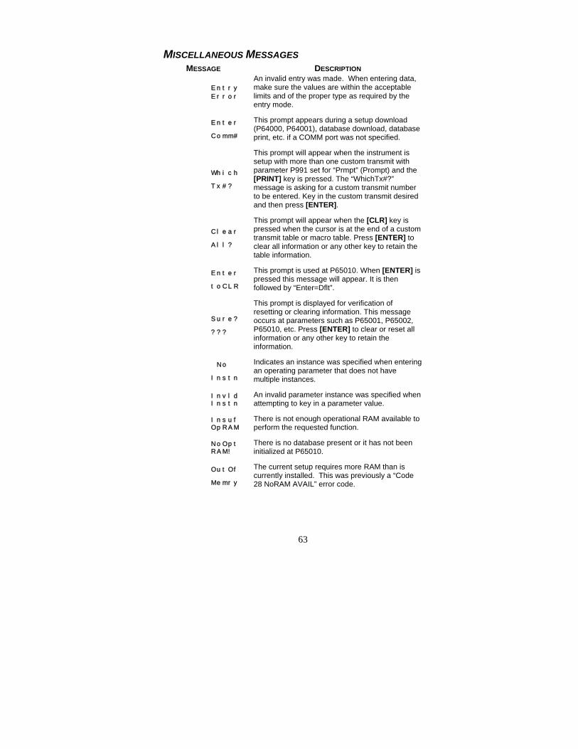
63
MISCELLANEOUS MESSAGES MESSAGE DESCRIPTION
Entry
Error
An invalid entry was made. When entering data, make sure the values are within the acceptable limits and of the proper type as required by the entry mode.
Enter
Comm#
This prompt appears during a setup download (P64000, P64001), database download, database print, etc. if a COMM port was not specified.
Which
Tx#?
This prompt will appear when the instrument is setup with more than one custom transmit with parameter P991 set for “Prmpt” (Prompt) and the [PRINT] key is pressed. The “WhichTx#?” message is asking for a custom transmit number to be entered. Key in the custom transmit desired and then press [ENTER].
Clear
All?
This prompt will appear when the [CLR] key is pressed when the cursor is at the end of a custom transmit table or macro table. Press [ENTER] to clear all information or any other key to retain the table information.
Enter
toCLR
This prompt is used at P65010. When [ENTER] is pressed this message will appear. It is then followed by “Enter=Dflt”.
Sure?
???
This prompt is displayed for verification of resetting or clearing information. This message occurs at parameters such as P65001, P65002, P65010, etc. Press [ENTER] to clear or reset all information or any other key to retain the information.
No
Instn
Indicates an instance was specified when entering an operating parameter that does not have multiple instances.
InvldInstn
An invalid parameter instance was specified when attempting to key in a parameter value.
InsufOpRAM
There is not enough operational RAM available to perform the requested function.
NoOptRAM!
There is no database present or it has not been initialized at P65010.
OutOf
Memry
The current setup requires more RAM than is currently installed. This was previously a “Code 28 NoRAM AVAIL” error code.


39-10-43401 GSE CheckWeighers
Users Guide Version 1.0