versa-spray ii ips electrostatic manual powder...
TRANSCRIPT
Versa-Spray� II IPS ElectrostaticManual Powder Spray Gun
Customer Product ManualPart 107017J
Issued 5/06
NORDSON CORPORATION AMHERST, OHIO USA
For parts and technical support, call the Industrial CoatingSystems Customer Support Center at (800) 433-9319 or
contact your local Nordson representative.
This document is subject to change without notice.Check http://emanuals.nordson.com for the latest version.

Part 107017J � 2006 Nordson Corporation
Table of ContentsSafety 1-1. . . . . . . . . . . . . . . . . . . . . . . . . . . . . . . . . . . .Introduction 1-1. . . . . . . . . . . . . . . . . . . . . . . . . . . . . . .Qualified Personnel 1-1. . . . . . . . . . . . . . . . . . . . . . . .Intended Use 1-1. . . . . . . . . . . . . . . . . . . . . . . . . . . . . .Regulations and Approvals 1-1. . . . . . . . . . . . . . . . . .Personal Safety 1-2. . . . . . . . . . . . . . . . . . . . . . . . . . .Fire Safety 1-2. . . . . . . . . . . . . . . . . . . . . . . . . . . . . . . .Grounding 1-3. . . . . . . . . . . . . . . . . . . . . . . . . . . . . . . .Action in the Event of a Malfunction 1-3. . . . . . . . . .Disposal 1-3. . . . . . . . . . . . . . . . . . . . . . . . . . . . . . . . . .Safety Labels 1-4. . . . . . . . . . . . . . . . . . . . . . . . . . . . .
Description 2-1. . . . . . . . . . . . . . . . . . . . . . . . . . . . . . .Introduction 2-1. . . . . . . . . . . . . . . . . . . . . . . . . . . . . . . .
Versions 2-2. . . . . . . . . . . . . . . . . . . . . . . . . . . . . . . .Operation 2-2. . . . . . . . . . . . . . . . . . . . . . . . . . . . . . . . .Options 2-3. . . . . . . . . . . . . . . . . . . . . . . . . . . . . . . . . . .
Nozzles and Deflectors 2-3. . . . . . . . . . . . . . . . . . .Lance Extensions 2-3. . . . . . . . . . . . . . . . . . . . . . . .Feed Hoses and Adapters 2-3. . . . . . . . . . . . . . . .Purge Adapters 2-3. . . . . . . . . . . . . . . . . . . . . . . . . .Upgrade Kits 2-4. . . . . . . . . . . . . . . . . . . . . . . . . . . .Ion Collector Kits 2-4. . . . . . . . . . . . . . . . . . . . . . . .
Specifications 2-4. . . . . . . . . . . . . . . . . . . . . . . . . . . . . .
Installation 3-1. . . . . . . . . . . . . . . . . . . . . . . . . . . . . . . .
Operation 4-1. . . . . . . . . . . . . . . . . . . . . . . . . . . . . . . . .Startup 4-1. . . . . . . . . . . . . . . . . . . . . . . . . . . . . . . . . . .Shutdown 4-2. . . . . . . . . . . . . . . . . . . . . . . . . . . . . . . . .Maintenance 4-3. . . . . . . . . . . . . . . . . . . . . . . . . . . . . . .
Daily Maintenance 4-3. . . . . . . . . . . . . . . . . . . . . . .Weekly Maintenance 4-3. . . . . . . . . . . . . . . . . . . .
Troubleshooting 5-1. . . . . . . . . . . . . . . . . . . . . . . . . .Continuity and Resistance Checks 5-3. . . . . . . . . . . .
Multiplier/Resistor Assembly Resistance Check 5-3. . . . . . . . . . . . . . . . . . . . . . .Resistor Resistance Check 5-4. . . . . . . . . . . . . . . .Nozzle Extension Resistor Resistance Check 5-5Gun Cable Continuity Checks 5-6. . . . . . . . . . . . .
Repair 6-1. . . . . . . . . . . . . . . . . . . . . . . . . . . . . . . . . . . .Multiplier Replacement 6-1. . . . . . . . . . . . . . . . . . . . .Cable Replacement 6-2. . . . . . . . . . . . . . . . . . . . . . . . .Resistor Replacement 6-4. . . . . . . . . . . . . . . . . . . . . .Contact Tip Replacement 6-5. . . . . . . . . . . . . . . . . . . .Nozzle Extension Resistor Replacement 6-6. . . . . .
Parts 7-1. . . . . . . . . . . . . . . . . . . . . . . . . . . . . . . . . . . . .Introduction 7-1. . . . . . . . . . . . . . . . . . . . . . . . . . . . . . .
Using the Illustrated Parts List 7-1. . . . . . . . . . . .Versa-Spray II IPS Manual Spray Gun Parts Lists 7-2
Spray Gun Part Number Reference Chart 7-2. . .Guns without Air 7-2. . . . . . . . . . . . . . . . . . . . . . . .Guns with Air 7-4. . . . . . . . . . . . . . . . . . . . . . . . . . .
Service Kits 7-6. . . . . . . . . . . . . . . . . . . . . . . . . . . . . . . .Service Kit Reference Chart − Versa-Spray II IPS Manual Spray Gun 7-6. . . . .Multiplier Service Kits 7-6. . . . . . . . . . . . . . . . . . . .Resistor Service Kit 7-6. . . . . . . . . . . . . . . . . . . . . .Cable Service Kits 7-7. . . . . . . . . . . . . . . . . . . . . . .Handle Service Kit 7-8. . . . . . . . . . . . . . . . . . . . . . .Trigger Service Kit 7-8. . . . . . . . . . . . . . . . . . . . . . .Nozzle Extension and Resistor Service Kits 7-9.
Recommended Spare Parts 7-10. . . . . . . . . . . . . . . . .Shorting Plug 7-10. . . . . . . . . . . . . . . . . . . . . . . . . . .Powder Feed Hose and Air Tubing 7-10. . . . . . . . .
Options 8-1. . . . . . . . . . . . . . . . . . . . . . . . . . . . . . . . . . .Options Reference Chart 8-1. . . . . . . . . . . . . . . . . . . .Purge Adapter Kits 8-2. . . . . . . . . . . . . . . . . . . . . . . . .
Purge Adapter Kit for Non-Metallic Powder Coatings 8-2. . . . . . . . . . . . .Purge Adapter Kit for Metallic Powder Coatings 8-3. . . . . . . . . . . . . . . . .
Gun Air Kits 8-4. . . . . . . . . . . . . . . . . . . . . . . . . . . . . . .Versa-Spray II Control Unit Gun Air Kit 8-4. . . . . .Versa-Spray Control Unit Gun Air Kit 8-5. . . . . . .
Ion Collector Kits 8-6. . . . . . . . . . . . . . . . . . . . . . . . . . .Miscellaneous Options 8-7. . . . . . . . . . . . . . . . . . . . . .
Low-Flow Hose Adapter 8-7. . . . . . . . . . . . . . . . . .Versa-Spray Control Unit and Manual Gun Upgrade Kit 8-8. . . . . . . . . . . . . . . . . .
Contact UsNordson Corporation welcomes requests for information, comments, andinquiries about its products. General information about Nordson can befound on the Internet using the following address:http://www.nordson.com.Address all correspondence to:
Nordson CorporationAttn: Customer Service300 Nordson DriveAmherst, OH 44001
NoticeThis is a Nordson Corporation publication which is protected by copyright.Original copyright date 1995. No part of this document may bephotocopied, reproduced, or translated to another language without theprior written consent of Nordson Corporation. The information containedin this publication is subject to change without notice.
Trademarks
Cross-Cut, Nordson, the Nordson logo, and Versa-Spray are registeredtrademarks of Nordson Corporation.
Tivar is a registered trademark of Poly-Hi Corporation.

Safety 1-1
Part 107017J� 2006 Nordson Corporation
Section 1Safety
Introduction Read and follow these safety instructions. Task- and equipment-specificwarnings, cautions, and instructions are included in equipmentdocumentation where appropriate.
Make sure all equipment documentation, including these instructions, isaccessible to all persons operating or servicing equipment.
Qualified Personnel Equipment owners are responsible for making sure that Nordson equipmentis installed, operated, and serviced by qualified personnel. Qualifiedpersonnel are those employees or contractors who are trained to safelyperform their assigned tasks. They are familiar with all relevant safety rulesand regulations and are physically capable of performing their assignedtasks.
Intended Use Use of Nordson equipment in ways other than those described in thedocumentation supplied with the equipment may result in injury to personsor damage to property.
Some examples of unintended use of equipment include
� using incompatible materials
� making unauthorized modifications
� removing or bypassing safety guards or interlocks
� using incompatible or damaged parts
� using unapproved auxiliary equipment
� operating equipment in excess of maximum ratings
Regulations and Approvals Make sure all equipment is rated and approved for the environment in whichit is used. Any approvals obtained for Nordson equipment will be voided ifinstructions for installation, operation, and service are not followed.
All phases of equipment installation must comply with all federal, state, andlocal codes.
Safety1-2
Part 107017J � 2006 Nordson Corporation
Personal Safety To prevent injury follow these instructions.
� Do not operate or service equipment unless you are qualified.
� Do not operate equipment unless safety guards, doors, or covers areintact and automatic interlocks are operating properly. Do not bypass ordisarm any safety devices.
� Keep clear of moving equipment. Before adjusting or servicing anymoving equipment, shut off the power supply and wait until theequipment comes to a complete stop. Lock out power and secure theequipment to prevent unexpected movement.
� Relieve (bleed off) hydraulic and pneumatic pressure before adjusting orservicing pressurized systems or components. Disconnect, lock out,and tag switches before servicing electrical equipment.
� Obtain and read Material Safety Data Sheets (MSDS) for all materialsused. Follow the manufacturer’s instructions for safe handling and useof materials, and use recommended personal protection devices.
� To prevent injury, be aware of less-obvious dangers in the workplacethat often cannot be completely eliminated, such as hot surfaces, sharpedges, energized electrical circuits, and moving parts that cannot beenclosed or otherwise guarded for practical reasons.
Fire Safety To avoid a fire or explosion, follow these instructions.
� Do not smoke, weld, grind, or use open flames where flammablematerials are being used or stored.
� Provide adequate ventilation to prevent dangerous concentrations ofvolatile materials or vapors. Refer to local codes or your material MSDSfor guidance.
� Do not disconnect live electrical circuits while working with flammablematerials. Shut off power at a disconnect switch first to preventsparking.
� Know where emergency stop buttons, shutoff valves, and fireextinguishers are located. If a fire starts in a spray booth, immediatelyshut off the spray system and exhaust fans.
� Clean, maintain, test, and repair equipment according to the instructionsin your equipment documentation.
� Use only replacement parts that are designed for use with originalequipment. Contact your Nordson representative for parts informationand advice.

Safety 1-3
Part 107017J� 2006 Nordson Corporation
Grounding WARNING: Operating faulty electrostatic equipment is hazardous and cancause electrocution, fire, or explosion. Make resistance checks part of yourperiodic maintenance program. If you receive even a slight electrical shockor notice static sparking or arcing, shut down all electrical or electrostaticequipment immediately. Do not restart the equipment until the problem hasbeen identified and corrected.
Grounding inside and around the booth openings must comply with NFPArequirements for Class 2, Division 1 or 2 Hazardous Locations. Refer toNFPA 33, NFPA 70 (NEC articles 500, 502, and 516), and NFPA 77, latestconditions.
� All electrically conductive objects in the spray areas shall be electricallyconnected to ground with a resistance of not more than 1 megohm asmeasured with an instrument that applies at least 500 volts to the circuitbeing evaluated.
� Equipment to be grounded includes, but is not limited to, the floor of thespray area, operator platforms, hoppers, photoeye supports, andblow-off nozzles. Personnel working in the spray area must begrounded.
� There is a possible ignition potential from the charged human body.Personnel standing on a painted surface, such as an operator platform,or wearing non-conductive shoes, are not grounded. Personnel mustwear shoes with conductive soles or use a ground strap to maintain aconnection to ground when working with or around electrostaticequipment.
� Operators must maintain skin-to-handle contact between their hand andthe gun handle to prevent shocks while operating manual electrostaticspray guns. If gloves must be worn, cut away the palm or fingers, wearelectrically conductive gloves, or wear a grounding strap connected tothe gun handle or other true earth ground.
� Shut off electrostatic power supplies and ground gun electrodes beforemaking adjustments or cleaning powder spray guns.
� Connect all disconnected equipment, ground cables, and wires afterservicing equipment.
Action in the Event of a Malfunction If a system or any equipment in a system malfunctions, shut off the systemimmediately and perform the following steps:
� Disconnect and lock out electrical power. Close pneumatic shutoffvalves and relieve pressures.
� Identify the reason for the malfunction and correct it before restarting theequipment.
Disposal Dispose of equipment and materials used in operation and servicingaccording to local codes.
Safety1-4
Part 107017J � 2006 Nordson Corporation
Safety Labels Table 1-1 contains the text of the safety label on this equipment. The safetylabel is provided to help you operate and maintain your equipment safely.
Table 1-1 Safety Label
Item Part Description
1. 244664
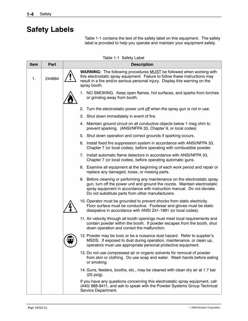
WARNING: The following procedures MUST be followed when working withthis electrostatic spray equipment. Failure to follow these instructions mayresult in a fire and/or serious personal injury. Display this warning on thespray booth.
1. NO SMOKING. Keep open flames, hot surfaces, and sparks from torchesor grinding away from booth.
2. Turn the electrostatic power unit off when the spray gun is not in use.
3. Shut down immediately in event of fire.
4. Maintain ground circuit on all conductive objects below 1 meg ohm toprevent sparking. (ANSI/NFPA 33, Chapter 9, or local codes)
5. Shut down operation and correct grounds if sparking occurs.
6. Install fixed fire suppression system in accordance with ANSI/NFPA 33,Chapter 7 (or local codes), before operating with combustible powder.
7. Install automatic flame detectors in accordance with ANSI/NFPA 33,Chapter 7 (or local codes), before operating automatic guns.
8. Examine all equipment at the beginning of each work period and repair orreplace any damaged, loose, or missing parts.
9. Before cleaning or performing any maintenance on the electrostatic spraygun, turn off the power unit and ground the nozzle. Maintain electrostaticspray equipment in accordance with instruction manual. Do not deviate.Do not substitute parts from other manufacturers.
10. Operator must be grounded to prevent shocks from static electricity.Floor surface must be conductive. Footwear and gloves must be staticdissipative in accordance with ANSI Z41-1991 (or local codes).
11. Air velocity through all booth openings must meet local requirements andcontain powder within the booth. If powder escapes from the booth, shutdown operation and correct the malfunction.
12. Powder may be toxic or be a nuisance dust hazard. Refer to supplier’sMSDS. If exposed to dust during operation, maintenance, or clean up,operators must use appropriate personal protective equipment.
13. Do not use compressed air or organic solvents for removal of powderfrom skin or clothing. Do use soap and water. Wash hands before eatingor smoking.
14. Guns, feeders, booths, etc., may be cleaned with clean dry air at 1.7 bar(25 psig).
If you have any questions concerning this electrostatic spray equipment, call (440) 988-9411, and ask to speak with the Powder Systems Group TechnicalService Department.

Description 2-1
Part 107017J� 2006 Nordson Corporation
Section 2Description
IntroductionThe Versa-Spray II integral power supply (IPS) manual powder spray gunelectrostatically charges and sprays organic powder coatings. The integralpower supply (multiplier) is user-replaceable. The spray gun is used with aVersa-Spray II three-gauge IPS control unit and a standard or low-flowpowder pump.
1400164A
1 2 3 4 5 6
7
8
9
10
1213
11
Figure 2-1 Versa-Spray II IPS Manual Powder Spray Gun with Gun Air Option
1. Hanger2. Extension3. Powder inlet body4. Nozzle extension (gun air only)5. Nozzle6. Deflector7. Electrode
8. Gun air tubing9. Feed hose adapter
10. Feed hose11. Trigger12. Feed hose bracket13. Cable

Description2-2
Part 107017J � 2006 Nordson Corporation
VersionsSee Figure 2-1.
The spray gun is available with a positive or negative multiplier and a 4-, 8-,or 12-meter, low-voltage power and control cable (13). All versions comewith a standard conical nozzle (5) with 19-mm deflector (6). They can alsobe ordered with a nozzle extension (4) with electrode cleaning air (gun air).Gun air flows through the nozzle extension and out around the electrode (7)to prevent some powder coatings such as metallics from building up onthe electrode.
OperationThe Versa-Spray II control unit supplies low-voltage dc power to the voltagemultiplier housed in the spray gun’s extension and body. The multipliergenerates the high electrostatic voltage needed for powder coating. Thevoltage generates a high-strength electrostatic field between the spray gunand the grounded part in front of the spray gun. The electrostatic fieldproduces a corona discharge around the electrode. A resistor in the spraygun between the multiplier and the electrode limits the current output tosafe levels.
Compressed air pumps the powder from the feed hopper, conveys itthrough the feed hose to the spray gun, and propels it toward theworkpieces. As the powder particles are sprayed through the corona, theypick up an electrostatic charge and are attracted to the workpieces.
The spray pattern is controlled by the shape of the nozzle used, the speedof the powder-conveying air as it exits the nozzle, and the electrostatic fieldgenerated between the electrode and the grounded workpiece. There areno controls on the spray gun except the trigger. The voltage controls andthe powder pump flow rate and atomizing air pressure regulators arehoused in the IPS control unit. A non-adjustable restrictor on the controlunit rear panel controls the gun air pressure. The pump and gun air startflowing when the trigger is pulled.

Description 2-3
Part 107017J� 2006 Nordson Corporation
OptionsRefer to the Options section in this manual for part numbers and illustrationsfor the options listed below. Contact your Nordson representative for moreinformation about these options.
Nozzles and DeflectorsNozzles and deflectors are available in the following sizes andconfigurations:
� 32- and 45-mm conical nozzles
� 14-, 16-, 19-, and 26-mm deflectors for conical nozzles
� 2.5-, 3-, 4-, and 6-mm Tivar and GFT (glass-filled PTFE) flat spraynozzles for organic powders
� 60� and 90� Cross-Cut nozzles
� castle nozzle (six radial slots)
Lance ExtensionsLance extensions are used to extend the length of the powder path to helpspray powder into recesses and interior corners. The extensions areequipped with 26-mm conical nozzles and are available in 150-, 300-, and450-mm (6-, 12-, and 18-in.) lengths.
Feed Hoses and AdaptersThe spray gun is equipped with a feed hose adapter for a 1/2-in. ID powderfeed hose. A low-flow hose adapter can be ordered for use with a low-flowhose (3/8-in. ID).
Purge AdaptersTwo purge adapters are available, one for non-metallic powders and one formetallic powders. The purge adapter is used to clean accumulated powderfrom the powder inlet body and nozzle. The purge adapter replaces thestandard feed hose adapter. The feed hose connects directly to the purgeadapter.
Description2-4
Part 107017J � 2006 Nordson Corporation
Upgrade KitsUpgrade kits are available to add a nozzle extension to a Versa-Spray IIspray gun. A fitting kit is available that connects to the air input port of aVersa-Spray control unit and delivers air at the proper pressure to the spraygun. A kit is also available that upgrades a Versa-Spray control unit andmanual spray gun by adding the AFC function to the control unit and theVersa-Spray II conical nozzle and deflector to the spray gun.
Ion Collector KitsThe ion collector can improve the smoothness and appearance of curedpowder coatings. It collects ions emitted from the spray gun’s chargingelectrode instead of allowing them to deposit on the part. This can reducethe rate of charge buildup in the powder deposited on the part, which mayreduce defects in the cured coating such as pinholing and orange peel.
Three kits are available: one for standard spray guns with or without nozzleextensions; and two for guns with 150- or 300-mm lance extensions, with orwithout nozzle extensions.
SpecificationsMaximum rated output voltage at the electrode: 80,000 volts 10 %
Maximum rated output current at the electrode: 0.180 mA 10 %
This equipment is rated for use in an explosive environment (Class II,Division I).
Installation 3-1
Part 107017J� 2006 Nordson Corporation
Section 3Installation
WARNING: Allow only qualified personnel to perform the following tasks.Follow the safety instructions in this document and all other relateddocumentation.
WARNING: All electrically conductive equipment in the spray area must begrounded. Ungrounded or poorly grounded equipment can store anelectrostatic charge which can give personnel a severe shock or arc andcause a fire or explosion.
See Figure 3-1.
1. Connect the feed hose (2) from the powder pump (3) outlet to the hoseadapter on the underside of the powder inlet body. Pinch the hose andsnap it into the hose bracket at the base of the gun handle.
NOTE: Keep the powder feed hose as short as possible, no more than12 m (39 ft) long if using 1/2-in. ID hose, or 4 m (13 ft) long if using 3/8-in. IDhose. Longer lengths may cause uneven powder flow.
2. To prevent the feed hose from kinking and cutting off the flow of powder,wrap spiral-cut tubing around the feed hose at the pump outlet and anyother place necessary. Use spiral-cut tubing to bundle together the feedhose, cable, and air tubing below the gun handle.
3. Connect the gun cable (9) to the GUN OUTPUT receptacle at the rear ofthe IPS control unit (10). Secure the cable to the control unit with theretaining nut on the cable end.
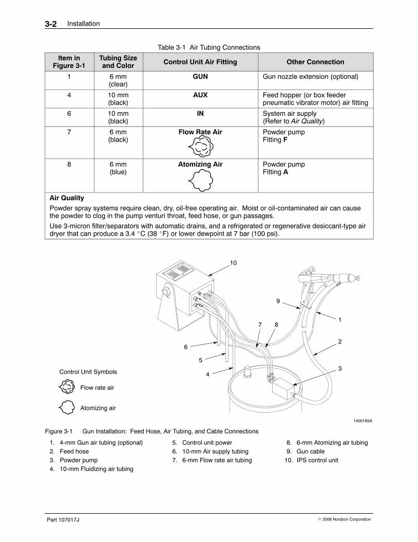
4. Connect the air tubing to the control unit, feed hopper, and spray gun asdescribed in Table 3-1.
NOTE: If you are installing gun air tubing, remove the plug from the controlunit GUN port. Wrap the restrictor threads with PTFE tape. Install therestrictor and connector that is shipped with the spray gun or included in thegun air kit in the GUN port.
5. Establish a path for the feed hose, air tubing, and gun cable. Make surethe hose and cable cannot be abraded, cut, or run over byheavy equipment.
Installation3-2
Part 107017J � 2006 Nordson Corporation
Table 3-1 Air Tubing Connections
Item inFigure 3-1
Tubing Sizeand Color Control Unit Air Fitting Other Connection
1 6 mm(clear)
GUN Gun nozzle extension (optional)
4 10 mm(black)
AUX Feed hopper (or box feederpneumatic vibrator motor) air fitting
6 10 mm(black)
IN System air supply(Refer to Air Quality)
7 6 mm(black)
Flow Rate Air Powder pumpFitting F
8 6 mm(blue)
Atomizing Air Powder pumpFitting A
Air Quality
Powder spray systems require clean, dry, oil-free operating air. Moist or oil-contaminated air can causethe powder to clog in the pump venturi throat, feed hose, or gun passages.
Use 3-micron filter/separators with automatic drains, and a refrigerated or regenerative desiccant-type airdryer that can produce a 3.4 �C (38 �F) or lower dewpoint at 7 bar (100 psi).
1400165A
Flow rate air
Atomizing air
Control Unit Symbols
6
10
5
4
9
1
2
3
7 8
Figure 3-1 Gun Installation: Feed Hose, Air Tubing, and Cable Connections
1. 4-mm Gun air tubing (optional)2. Feed hose3. Powder pump4. 10-mm Fluidizing air tubing
5. Control unit power6. 10-mm Air supply tubing7. 6-mm Flow rate air tubing
8. 6-mm Atomizing air tubing9. Gun cable
10. IPS control unit
Operation 4-1
Part 107017J� 2006 Nordson Corporation
Section 4Operation
WARNING: Allow only qualified personnel to perform the following tasks.Follow the safety instructions in this document and all other relateddocumentation.
WARNING: This equipment can be dangerous unless it is used inaccordance with the rules laid down in this manual.
Startup WARNING: Do not operate the spray gun if the resistor and multiplierresistances are not within the ranges specified in this manual. Failure toobserve this warning may result in personal injury, fire, and propertydamage.
Before turning on the IPS control unit, make sure that the
� booth exhaust fan is on,
� powder recovery system is operating, and
� powder supply in the feed hopper is adequately fluidized.
Refer to the appropriate equipment manuals for startup procedures.
1. Make sure the cable, feed hose, and air tubing are correctly connectedto the spray gun, powder pump, and IPS control unit.
2. Turn the IPS control unit main power switch to the on position.
3. Adjust the control unit air pressure regulators:
NOTE: The pressures given are average starting points. Pressures willvary according to required film build, line speed, and part configuration.Adjust the pressures to obtain the desired results.
Air Pressure Typical Setting Description
Flow rate 1.4 bar (20 psi) Controls the volume of thepowder delivered to the spraygun.
Atomizing 2.1 bar (30 psi) Controls the velocity anddensity (powder-to-air ratio)of the powder.
Gun (optional) Fixed Prevents powder frombuilding up on the electrode.

Operation4-2
Part 107017J � 2006 Nordson Corporation
Startup (contd)
WARNING: The operator must maintain skin contact with the the gunhandle. If wearing gloves, cut away the palm. Failure to observe thiswarning could result in a shock.
4. Point the spray gun into the booth, pull the trigger, and test the spraypattern. Adjust the flow rate and atomizing air pressures until you obtainthe desired pattern.
NOTE: The following steps describe electrostatic voltage settings made ona Versa-Spray II control unit that includes AFC controls. A Versa-Spray IIgun can be used with older Versa-Spray control units without AFC controls.Only the kV mode will be available unless the optional current limit kit isinstalled. Refer to the control unit manual for specific instructions.
5. Use the control unit’s kV/AFC dial to select an operating mode:
� kV Mode: Push the dial in. Rotate it fully clockwise for maximumvoltage.
� AFC Mode: Pull the dial out. Rotate it to position 4, whichrepresents approximately 40 A (microamps).
6. Set the control unit’s kV/A switch to view the desired output value onthe digital display.
NOTE: When a spray gun is first put into service, set the kV/AFC dial tothe kV mode. Turn the dial to the maximum setting and record the Aoutput with no parts in front of the spray gun. Monitor the A outputdaily under the same conditions. A significant increase in A outputindicates a probable short in the spray gun resistor. A significantdecrease indicates a failing resistor or voltage multiplier.
7. Coat a part and adjust the voltage settings (kV or AFC) and airpressures to achieve the desired results.
Shutdown
WARNING: Turn off the electrostatic voltage and ground the gun electrodebefore making adjustments to the spray gun or nozzle.
1. Turn the control unit main power switch to the off position. Ground thegun electrode to discharge any residual voltage.
2. Perform the Daily Maintenance procedure.
For information on the operation of other components of your powder spraysystem, refer to their manuals.

Operation 4-3
Part 107017J� 2006 Nordson Corporation
Maintenance
WARNING: Turn off the electrostatic voltage and ground the gun electrodebefore performing the following tasks. Failure to observe this warning couldresult in a severe shock.
Daily Maintenance 1. Disconnect the powder feed hose from the pump. Point the spray gun
into the booth and blow the powder out of the hose and spray gun withlow-pressure compressed air. Never blow air through the powder feedhose from the spray gun into the pump.
2. See Figure 4-1. Remove the nozzle parts (items 4−7) from the spraygun.
3. Loosen the set screw (8) and pull the powder inlet body (3) straight offthe gun.
4. Clean the parts with a low-pressure air gun. Wipe the parts with aclean, dry cloth.
5. Blow powder off the resistor probe (2) and extension (1). Wipe themwith a clean, dry cloth. Carefully remove fused powder from the partswith a wooden or plastic dowel or similar tool. Do not use tools that willscratch the plastic. Powder will build up and impact-fuse on anyscratches.
NOTE: If necessary, use a cloth dampened with isopropyl or ethylalcohol to clean the powder path parts. Remove the O-rings first. Donot immerse the spray gun in alcohol. Do not use any other solvents.
6. Inspect the powder path parts for wear. Replace worn parts.
7. Assemble the spray gun. Rotate items (4), (6), (7), and (9) at least 30�from their previous position to prevent uneven wear and lopsidedpatterns.
Weekly Maintenance Check the resistance of the multiplier/resistor probe assembly with amegohmmeter, as described in the Troubleshooting section. Replace themultiplier, resistor, or both, if the resistance readings do not fall within thespecified ranges.

Operation4-4
Part 107017J � 2006 Nordson Corporation
Weekly Maintenance (contd)
1400171A
3
4
2
1
896
7
5
Figure 4-1 Daily Maintenance
1. Extension2. Resistor probe3. Powder inlet body
4. Wear sleeve5. Nozzle adapter6. Conical nozzle
7. Deflector8. Set screw9. Hose adapter
Note: Item 4 is used only on guns without air. Item 5 is used only on guns with air.

Troubleshooting 5-1
Part 107017J� 2006 Nordson Corporation
Section 5Troubleshooting
WARNING: Allow only qualified personnel to perform the following tasks.Follow the safety instructions in this document and all other relateddocumentation.
This section contains troubleshooting procedures. These procedures coveronly the most common problems that you may encounter. If you cannotsolve the problem with the information given here, contact your localNordson representative for help.
If you are having problems with the electrostatic components of the spraygun, check their continuity and resistance with the procedures at the end ofthis section.
� multiplier/resistor assembly continuity and resistance
� resistor continuity and resistance
� nozzle extension resistor continuity and resistance
� gun cable continuity
No. Problem Page
1. Uneven pattern; unsteady or inadequate powder flow 5-1
2. Voids in powder pattern 5-2
3. Loss of wrap; poor transfer efficiency 5-2
4. No kV output from spray gun 5-2
Problem Possible Cause Corrective Action
1. Uneven pattern;unsteady orinadequate powderflow
Blockage in spray gun, feed hose,or pump
Disconnect the feed hose from thepump. Blow out the hose withcompressed air. Disassemble thespray gun and pump and clean them.Replace the hose if it is clogged withfused powder.
Deflector or nozzle worn, affectingpattern
Remove the deflector and nozzle.Clean and inspect them. Replaceworn parts. If excessive wear orimpact-fusion is a problem, reducethe flow rate and atomizing airpressures.
Damp powder Check the powder supply, air filters,and dryer. Replace the powdersupply if it is contaminated.
Continued...

Troubleshooting5-2
Part 107017J � 2006 Nordson Corporation
Problem Possible Cause Corrective Action
1. Uneven pattern;unsteady orinadequate powderflow (contd)
Low atomizing or flow rate airpressure
Increase the atomizing and/or flowrate air pressures.
Improper fluidization of powder inhopper
Increase the fluidizing air pressure.Remove the powder from hopper andclean or replace the fluidizing plate, ifcontaminated.
2. Voids in powderpattern
Worn nozzle or deflector Remove the deflector and nozzle.Inspect and replace them if worn.
Plugged powder path Remove the nozzle parts and powderpath from the spray gun and cleanthem.
3. Loss of wrap; poortransfer efficiency
Low electrostatic voltage Increase the electrostatic voltage.
Resistor or IPS control unit failure Check the multiplier/resistor probeassembly with a megohmmeter for195−270 megohms at 500 volts. Ifthe reading is out-of-range, check theresistor probe separately.
Poorly grounded parts Check the conveyor chain, rollers,and part hangers for powder buildup.The resistance between the partsand ground must be 1 megohm orless. For best results, 500 ohms orless is recommended.
Failed nozzle extension resistor Check the resistor with amegohmmeter for 18−22 megohmsat 500 volts.
4. No kV output fromspray gun
Malfunctioning trigger switch Check for continuity between pins 1and 2 (control unit end of cable) withthe switch actuated. If no continuityis found, replace the cable.
Damaged gun cable Check the continuity of the cablewires, from pin to pin. Replace thecable if any opens or shorts found.
Malfunctioning voltage multiplier Use the optional shorting plug and amegohmmeter to check the continuityand resistance of themultiplier/resistor assembly for195−270 megohms at 500 volts. Noburn-throughs or arc tracks should bevisible on any parts.
Failed gun resistor Check the resistor with amegohmmeter for153−187 megohms at 500 volts.
Malfunctioning IPS control unit Check for 21 Vdc between pins 2 and3 (spray gun end of cable) with thetrigger depressed.
Failed nozzle extension resistor Check the resistor with amegohmmeter for 18−22 megohmsat 500 volts.
Troubleshooting 5-3
Part 107017J� 2006 Nordson Corporation
Continuity and Resistance Checks
WARNING: Turn off the electrostatic voltage and ground the gun electrodebefore performing the following tasks. Failure to observe this warning couldresult in a severe shock.
NOTE: All three pins in the multiplier connector must be shorted together tocheck the continuity and resistance of the multiplier or multiplier/resistorassembly, or the multiplier could be damaged. The optional shorting plugmakes these tasks easy. Refer to the Options section for the part number.
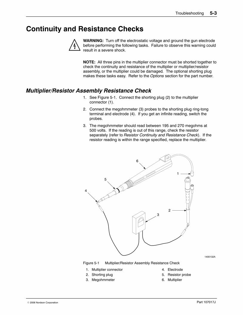
Multiplier/Resistor Assembly Resistance Check1. See Figure 5-1. Connect the shorting plug (2) to the multiplier
connector (1).
2. Connect the megohmmeter (3) probes to the shorting plug ring-tongterminal and electrode (4). If you get an infinite reading, switch theprobes.
3. The megohmmeter should read between 195 and 270 megohms at500 volts. If the reading is out of this range, check the resistorseparately (refer to Resistor Continuity and Resistance Check). If theresistor reading is within the range specified, replace the multiplier.
1400132A
4
5
6
1
23
Figure 5-1 Multiplier/Resistor Assembly Resistance Check
1. Multiplier connector2. Shorting plug3. Megohmmeter
4. Electrode5. Resistor probe6. Multiplier

Troubleshooting5-4
Part 107017J � 2006 Nordson Corporation
Resistor Resistance Check1. Perform steps 1 through 3 in the Multiplier/Resistor Assembly Continuity
and Resistance Check procedure.
2. See Figure 5-2. Unscrew the resistor probe (2) from the multiplier (4).
3. Check the resistor with a megohmmeter. The megohmmeter shouldread between 153 and 187 megohms at 500 volts. If the reading is outof this range, replace the resistor probe.
1400133A
1
2
3
4
Figure 5-2 Resistor Resistance Check
1. Electrode2. Resistor probe
3. Resistor spring 4. Multiplier

Troubleshooting 5-5
Part 107017J� 2006 Nordson Corporation
Nozzle Extension Resistor Resistance Check1. See Figure 5-3. Remove the resistor holder/spider/wear sleeve/
assembly (1, 2, 3) from the nozzle adapter (4).
2. Unscrew the resistor holder (1) from the spider/wear sleeveassembly (3) and remove the resistor (2).
3. Check the resistor with a megohmmeter. The megohmmeter shouldread between 18 and 22 megohms at 500 volts. If the reading is out ofthis range, replace the resistor.
1400196A
3
4
2
1
Figure 5-3 Nozzle Extension Resistor Resistance Check
1. Resistor holder2. Resistor
3. Spider/wear sleeve 4. Nozzle adapter
Troubleshooting5-6
Part 107017J � 2006 Nordson Corporation
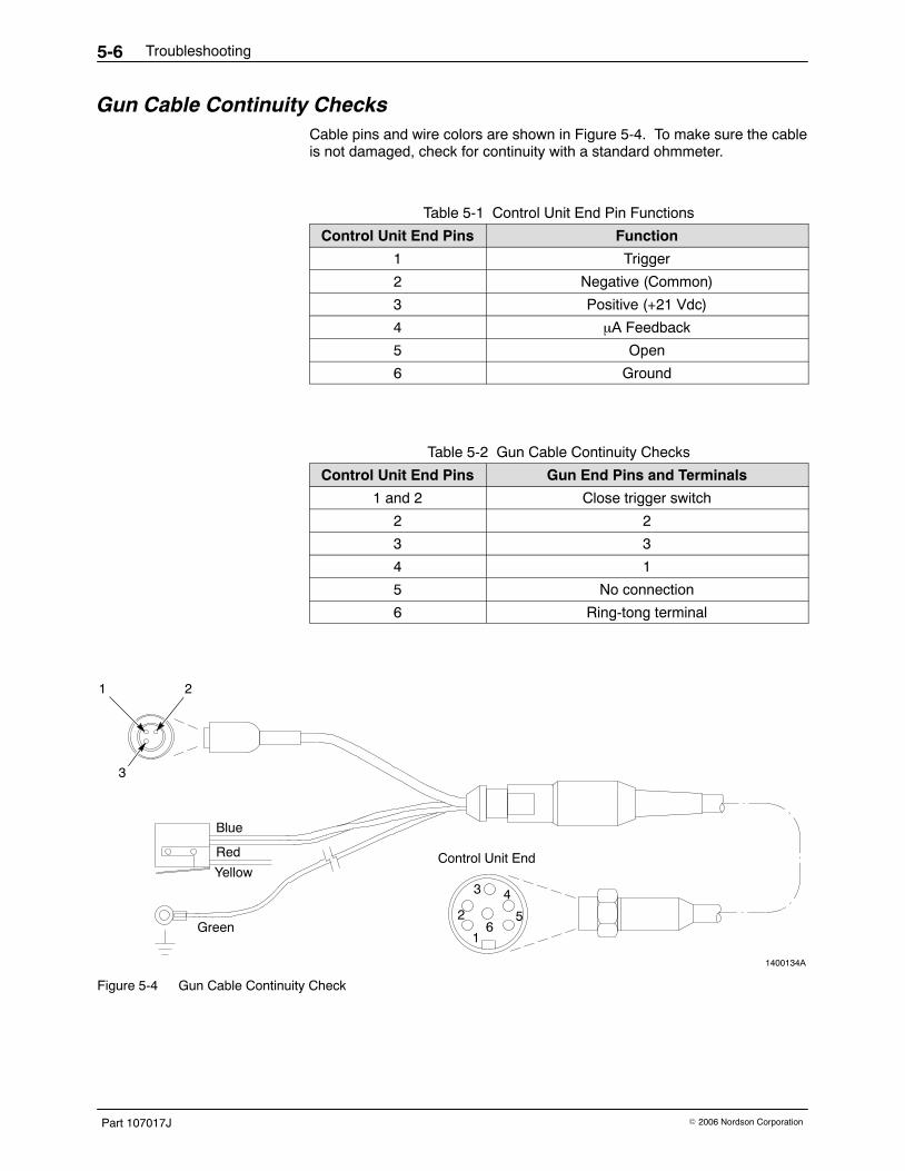
Gun Cable Continuity ChecksCable pins and wire colors are shown in Figure 5-4. To make sure the cableis not damaged, check for continuity with a standard ohmmeter.
Table 5-1 Control Unit End Pin Functions
Control Unit End Pins Function
1 Trigger
2 Negative (Common)
3 Positive (+21 Vdc)
4 A Feedback
5 Open
6 Ground
Table 5-2 Gun Cable Continuity Checks
Control Unit End Pins Gun End Pins and Terminals
1 and 2 Close trigger switch
2 2
3 3
4 1
5 No connection
6 Ring-tong terminal
1400134A
Green1
2
3 4
56
Control Unit End
Blue
Red
Yellow
1 2
3
Figure 5-4 Gun Cable Continuity Check

Repair 6-1
Part 107017J� 2006 Nordson Corporation
Section 6Repair
WARNING: Allow only qualified personnel to perform the following tasks.Follow the safety instructions in this document and all other relateddocumentation.
Multiplier Replacement Multiplier service kits contain a new multiplier/resistor probe assembly andextension. Follow the steps below to replace your old multiplier with a newmultiplier/resistor probe assembly.
1. Remove and clean the powder path parts as described in the DailyMaintenance procedure in the Operation section of this manual.
2. See Figure 6-1. Loosen the three captive screws (8) in the cover (7).The O-rings (6) hold the screws in the cover. Lift the cover off thehandle (1).
3. Remove the screw (15) securing the multiplier heat sink bracket to thehanger (17). Remove the cable ground wire.
4. Loosen the connector swivel nut and disconnect the cable (13) from themultiplier connector (14).
5. Remove the extension (3) and multiplier/resistor probe assembly (16)from the handle.
6. Loosen and remove the cable nut (4). Use a wrench if necessary.
7. Remove the multiplier/resistor probe assembly from the extension.
8. If you are replacing the old extension with the new one included in thekit, remove the two screws (5) that secure the hanger (17) to theextension and remove the hanger. Install the hanger on thenew extension.
9. Perform the disassembly steps in reverse to install the newmultiplier/resistor probe assembly in your spray gun.
Repair6-2
Part 107017J � 2006 Nordson Corporation
Cable Replacement1. Remove the cover from the handle and disconnect the cable from the
multiplier as described in the Multiplier Replacement procedure.
2. See Figure 6-1. Remove the two screws (9), lock washers (10) and flatwashers (11). Remove the trigger switch and actuator (12) from thehandle (1).
3. Rotate the hose bracket (2) slightly and release the cable. Note how thecable fits into the hose bracket.
4. Fit the new cable into the hose bracket and route the ground wirearound the end of the multiplier. Secure the ground wire to thehanger (17) with the screw (15).
5. Connect the cable to the multiplier connector (14). Arrange the wiringso that it will not be pinched between the handle and the cover when thecover is installed.
6. The cable service kit includes new screws (9), washers (10, 11), and anactuator (12). Install the actuator on the trigger switch. Secure both tothe two threaded inserts in the handle with the screws and washers.
7. Install the cover (7) on the handle.

Repair 6-3
Part 107017J� 2006 Nordson Corporation
1400135A
1
2
4
3
5
6
7
8
13 910
11
12
17
15
14
16
Figure 6-1 Multiplier and Cable Replacement
1. Handle2. Hose bracket3. Extension4. Cable nut5. Screws (2)6. O-rings (3)
7. Cover8. Captive screws (3)9. Screws (2)
10. Lock washers (2)11. Flat washers (2)12. Actuator
13. Cable14. Multiplier connector15. Screw (1)16. Multiplier/resistor probe
assembly17. Hanger

Repair6-4
Part 107017J � 2006 Nordson Corporation
Resistor Replacement Resistor service kits contain a new resistor, holder, and contact tip. Theyare assembled, greased, and ready to be installed on a multiplier. A 3-ccapplicator filled with dielectric grease is included.
1. Remove the multiplier/resistor probe assembly from the extension asdescribed in the Multiplier Replacement procedure.
2. See Figure 6-2. Unscrew the old resistor probe (2) from themultiplier (4). Clean the multiplier well (5).
3. Remove the shipping container and protective caps from the new probe.
WARNING: All air in the multiplier well, resistor holder, and contact tip mustbe replaced by dielectric grease. High voltage can arc through air pockets,affect electrostatic performance, possibly burn through the spray gun, andcreate a fire or explosion hazard.
4. Inject dielectric grease into the multiplier well (5) until it is completely full.Use the 3-cc applicator supplied with the kit.
5. Fill the new resistor spring (3) and the resistor probe cavity (6)completely with dielectric grease.
6. Unscrew the contact tip (1) from the resistor probe (2).
7. Screw the new resistor probe onto the multiplier. Do not overtighten.
8. Apply dielectric grease to the threads of the new contact tip and into theend of the probe.
9. Screw the contact tip into the resistor probe. Do not overtighten. Wipeexcess grease off the contact tip and multiplier.
10. Install the probe and multiplier into the extension and secure them withthe cable nut. Connect the cable to the multiplier and assemble thespray gun.

Repair 6-5
Part 107017J� 2006 Nordson Corporation
Contact Tip Replacement1. Remove and clean the powder path parts as described in the Daily
Maintenance procedure in the Operation section of this manual. Wipeall powder off the resistor probe.
2. See Figure 6-2. Unscrew the damaged contact tip (1) from the end ofthe resistor probe (2).
3. Apply dielectric grease to the threads of the new contact tip and into theend of the probe.
4. Screw the new contact tip into the resistor probe. Do not overtighten.Wipe excess grease off the contact tip and multiplier.
1400136A
4
3
215
6
Figure 6-2 Resistor and Contact Tip Replacement
1. Contact tip2. Resistor probe
3. Resistor spring4. Multiplier
5. Multiplier well6. Resistor probe cavity
Note: Clean item 5, grease items 1, 3, 5, and 6.

Repair6-6
Part 107017J � 2006 Nordson Corporation
Nozzle Extension Resistor Replacement This resistor in this procedure is only used on spray guns with electrodecleaning air.
1. See Figure 6-3. Remove the nozzle extension (2) from the powder inletbody (1).
2. Remove the deflector (6) and conical nozzle (5).
3. Push the wear sleeve/spider/resistor holder assembly (4) out of thenozzle adapter (3).
4. Unscrew the resistor holder (8) from the spider and remove theresistor (7).
5. Install the new resistor in the holder and screw the resistor holder ontothe spider finger-tight.
6. Align the pin (9) on the spider with the slot (10) in the nozzle adapter.Press the wear sleeve/spider/resistor holder assembly into the nozzleadapter.
7. Finish assembling the nozzle extension and install it onto the powderinlet body.
1400177A
4
3
9
10
7
8
3
4
5
6
1
2
Figure 6-3 Nozzle Extension Resistor Replacement
1. Powder inlet body2. Nozzle extension3. Nozzle adapter4. Wear sleeve/spider/resistor holder
5. Conical nozzle6. Deflector7. Resistor
8. Resistor holder9. Pin
10. Slot
Parts 7-1
Part 107017J� 2006 Nordson Corporation
Section 7Parts
Introduction To order parts, call the Nordson Customer Service Center or your localNordson representative. Use this five-column parts list, and theaccompanying illustration, to describe and locate parts correctly.
Using the Illustrated Parts List Numbers in the Item column correspond to numbers that identify parts inillustrations following each parts list. The code NS (not shown) indicatesthat a listed part is not illustrated. A dash (—) is used when the part numberapplies to all parts in the illustration.
The number in the Part column is the Nordson Corporation part number. Aseries of dashes in this column (- - - - - -) means the part cannot be orderedseparately.
The Description column gives the part name, as well as its dimensions andother characteristics when appropriate. Indentions show the relationshipsbetween assemblies, subassemblies, and parts.
� If you order the assembly, items 1 and 2 will be included.
� If you order item 1, item 2 will be included.
� If you order item 2, you will receive item 2 only.
The number in the Quantity column is the quantity required per unit,assembly, or subassembly. The code AR (As Required) is used if the partnumber is a bulk item ordered in quantities or if the quantity per assemblydepends on the product version or model.
Letters in the Note column refer to notes at the end of each parts list. Notescontain important information about usage and ordering. Special attentionshould be given to notes.
Item Part Description Quantity Note— 0000000 Assembly 11 000000 � Subassembly 2 A2 000000 � � Part 1
Parts7-2
Part 107017J � 2006 Nordson Corporation
Versa-Spray II IPS Manual Spray Gun Parts Lists
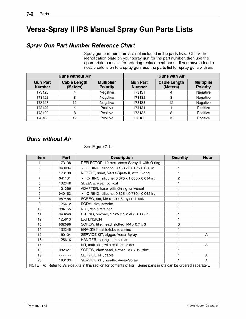
Spray Gun Part Number Reference ChartSpray gun part numbers are not included in the parts lists. Check theidentification plate on your spray gun for the part number, then use theappropriate parts list for ordering replacement parts. If you have added anozzle extension to a spray gun, use the parts list for spray guns with air.
Guns without Air Guns with Air
Gun PartNumber
Cable Length(Meters)
MultiplierPolarity
Gun PartNumber
Cable Length(Meters)
MultiplierPolarity
173125 4 Negative 173131 4 Negative173126 8 Negative 173132 8 Negative173127 12 Negative 173133 12 Negative173128 4 Positive 173134 4 Positive173129 8 Positive 173135 8 Positive173130 12 Positive 173136 12 Positive
Guns without Air See Figure 7-1.
Item Part Description Quantity Note1 173138 DEFLECTOR, 19 mm, Versa-Spray II, with O-ring 12 940084 � O-RING, silicone, 0.188 x 0.312 x 0.063 in. 13 173139 NOZZLE, short, Versa-Spray II, with O-ring 14 941181 � O-RING, silicone, 0.875 x 1.063 x 0.094 in. 25 132348 SLEEVE, wear, conical 16 134386 ADAPTER, hose, with O-ring, universal 17 940163 � O-RING, silicone, 0.625 x 0.750 x 0.063 in. 18 982455 SCREW, set, M6 x 1.0 x 8, nylon, black 19 125612 BODY, inlet, powder 110 984165 NUT, cable retainer 111 940243 O-RING, silicone, 1.125 x 1.250 x 0.063 in. 112 125613 EXTENSION 113 982098 SCREW, fillet head, slotted, M4 x 0.7 x 6 314 132345 BRACKET, cable/tube retaining 115 160104 SERVICE KIT, trigger, Versa-Spray 1 A16 125616 HANGER, handgun, modular 117 - - - - - - KIT, multiplier, with resistor probe 1 A18 982327 SCREW, chez head, slotted, M4 x 12, zinc 119 - - - - - - SERVICE KIT, cable 1 A20 160103 SERVICE KIT, handle, Versa-Spray 1 A
NOTE A: Refer to Service Kits in this section for contents of kits. Some parts in kits can be ordered separately.

Parts 7-3
Part 107017J� 2006 Nordson Corporation
1400178A
20
14
9
13
13
19
18
16
17
12
1110
6 7 8
20
15
5
3
21
4
Figure 7-1 Versa-Spray II Guns without Air
Parts7-4
Part 107017J � 2006 Nordson Corporation
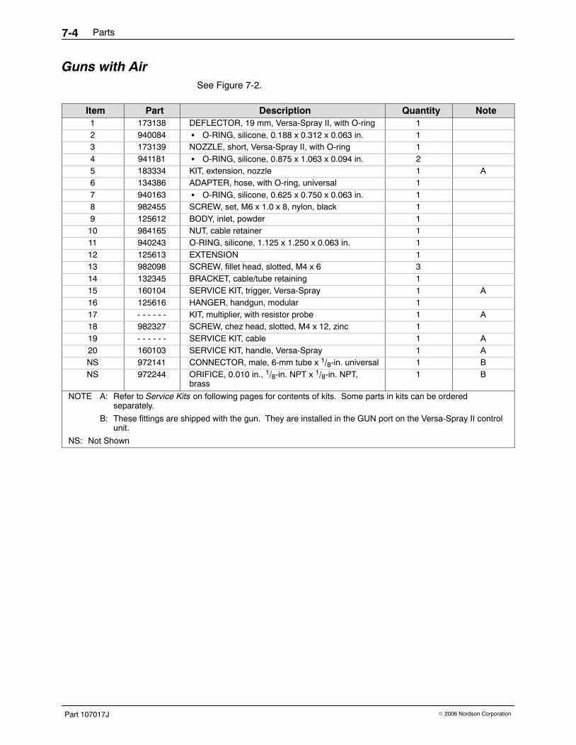
Guns with Air See Figure 7-2.
Item Part Description Quantity Note1 173138 DEFLECTOR, 19 mm, Versa-Spray II, with O-ring 12 940084 � O-RING, silicone, 0.188 x 0.312 x 0.063 in. 13 173139 NOZZLE, short, Versa-Spray II, with O-ring 14 941181 � O-RING, silicone, 0.875 x 1.063 x 0.094 in. 25 183334 KIT, extension, nozzle 1 A6 134386 ADAPTER, hose, with O-ring, universal 17 940163 � O-RING, silicone, 0.625 x 0.750 x 0.063 in. 18 982455 SCREW, set, M6 x 1.0 x 8, nylon, black 19 125612 BODY, inlet, powder 110 984165 NUT, cable retainer 111 940243 O-RING, silicone, 1.125 x 1.250 x 0.063 in. 112 125613 EXTENSION 113 982098 SCREW, fillet head, slotted, M4 x 6 314 132345 BRACKET, cable/tube retaining 115 160104 SERVICE KIT, trigger, Versa-Spray 1 A16 125616 HANGER, handgun, modular 117 - - - - - - KIT, multiplier, with resistor probe 1 A18 982327 SCREW, chez head, slotted, M4 x 12, zinc 119 - - - - - - SERVICE KIT, cable 1 A20 160103 SERVICE KIT, handle, Versa-Spray 1 ANS 972141 CONNECTOR, male, 6-mm tube x 1/8-in. universal 1 BNS 972244 ORIFICE, 0.010 in., 1/8-in. NPT x 1/8-in. NPT,
brass1 B
NOTE A: Refer to Service Kits on following pages for contents of kits. Some parts in kits can be orderedseparately.
B: These fittings are shipped with the gun. They are installed in the GUN port on the Versa-Spray II controlunit.
NS: Not Shown

Parts 7-5
Part 107017J� 2006 Nordson Corporation
1400179A
20
14
9
13
13
19
18
16
17
12
1110
6 7 8
20
15
5
3
21
4
Figure 7-2 Versa-Spray II Guns with Air

Parts7-6
Part 107017J � 2006 Nordson Corporation
Service KitsService kits are used to replace parts on the Versa-Spray II IPS manualspray guns. Refer to the Guns Used On and Note columns in the SprayGun Part Number Reference Chart before ordering.
Service Kit Reference Chart − Versa-Spray II IPS Manual Spray Gun Part Description Guns Used On Note
1014039 POSITIVE MULTIPLIER service kit, 80 kV, with resistor probe Positive polarity A1014038 NEGATIVE MULTIPLIER service kit, 80 kV, with resistor
probeNegative polarity A
134376 RESISTOR WITH HOLDER service kit All B133716 4-METER CABLE, IPS All C133715 8-METER CABLE, IPS All C163408 12-METER CABLE, IPS All C160103 HANDLE service kit, Versa-Spray All160104 TRIGGER service kit, Versa-Spray All183334 NOZZLE EXTENSION service kit, Versa-Spray II with air only183645 RESISTOR WITH HOLDER service kit, Versa-Spray II
(nozzle extension)with air only
183646 RESISTOR service kit, nozzle extension, Versa-Spray II with air onlyNOTE A: Check multiplier polarity before ordering. Compare part number on gun label with part number and
description in the Spray Gun Part Number Reference Chart. Gun polarity can be switched by changingmultiplier.
B: Replaces the multiplier resistor.
C: Order cable service kit according to length of cable desired.
Multiplier Service KitsMultiplier kits include the resistor, multiplier, and extension. If replacing justthe resistor, order the Resistor Service Kit.
Part Description Note1014038 SERVICE KIT, negative multiplier, 80 kV, with resistor probe1014039 SERVICE KIT, positive multiplier, 80 kV, with resistor probe125613 � EXTENSION134376 � SERVICE KIT, holder, resistor- - - - - - � MULTIPLIER, 80 kV, Versa-Spray

Parts 7-7
Part 107017J� 2006 Nordson Corporation
Resistor Service KitSee Figure 7-3.
Item Part Description Quantity Note— 134376 SERVICE KIT, holder, resistor 11 132748 � CONTACT, cable 12 940117 � O-RING, silicone, 0.312 x 0.438 x 0.063 in. 13 - - - - - - � HOLDER, resistor 14 - - - - - - � RESISTOR 1
NS 245733 � GREASE, dielectric, 3-cc applicator 1NS: Not Shown
1400139A
2 134
Figure 7-3 Resistor Service Kit
Cable Service KitsSee Figure 7-4.
Item Part Description Quantity Note— 133716 4-METER CABLE service kit, IPS 1— 133715 8-METER CABLE service kit, IPS 1— 163408 12-METER CABLE service kit, IPS 11 - - - - - - � CABLE 12 132336 � ACTUATOR, switch 13 1070246 � SCREW, pan head, #2-56 x 0.437 in., slotted,
zinc2
4 983113 � WASHER, lock, e, split, 2, steel, zinc 25 983510 � WASHER, flat, e, 0.094 x 0.188 x 0.025 in.,
brown2
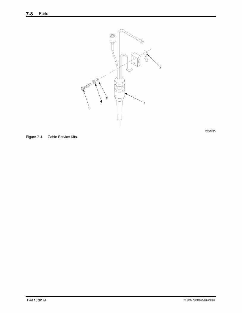
Parts7-8
Part 107017J � 2006 Nordson Corporation
1400138A
3
45
2
1
Figure 7-4 Cable Service Kits

Parts 7-9
Part 107017J� 2006 Nordson Corporation
Handle Service KitSee Figure 7-5.
Item Part Description Quantity Note1 160103 SERVICE KIT, handle, Versa-Spray 1 A2 - - - - - - � HANDLE, gun 13 - - - - - - � HANDLE, cover 14 940060 � O-RING, Viton, 0.125 x 0.250 x 0.063 in. 35 981626 � SCREW, captive, slotted, M4 x 12, black 3
NOTE A: Customer must provide spray gun part number and serial number when ordering.
Trigger Service KitSee Figure 7-5.
Item Part Description Quantity Note6 160104 SERVICE KIT, trigger, Versa-Spray 17 132334 � PIVOT, trigger 18 125617 � TRIGGER, hand gun, modular 19 133783 � SPRING, trigger, return 110 982370 � SCREW, pan head, slotted, M2 x 5 1
1400140A
4
5
3
2
1 6
10
8
9
7
Figure 7-5 Handle and Trigger Service Kits
Parts7-10
Part 107017J � 2006 Nordson Corporation
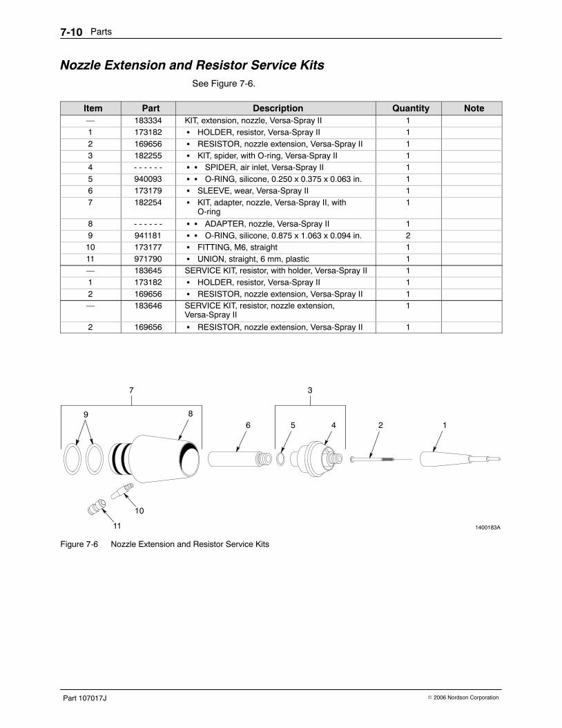
Nozzle Extension and Resistor Service KitsSee Figure 7-6.
Item Part Description Quantity Note— 183334 KIT, extension, nozzle, Versa-Spray II 11 173182 � HOLDER, resistor, Versa-Spray II 12 169656 � RESISTOR, nozzle extension, Versa-Spray II 13 182255 � KIT, spider, with O-ring, Versa-Spray II 14 - - - - - - � � SPIDER, air inlet, Versa-Spray II 15 940093 � � O-RING, silicone, 0.250 x 0.375 x 0.063 in. 16 173179 � SLEEVE, wear, Versa-Spray II 17 182254 � KIT, adapter, nozzle, Versa-Spray II, with
O-ring1
8 - - - - - - � � ADAPTER, nozzle, Versa-Spray II 19 941181 � � O-RING, silicone, 0.875 x 1.063 x 0.094 in. 210 173177 � FITTING, M6, straight 111 971790 � UNION, straight, 6 mm, plastic 1— 183645 SERVICE KIT, resistor, with holder, Versa-Spray II 11 173182 � HOLDER, resistor, Versa-Spray II 12 169656 � RESISTOR, nozzle extension, Versa-Spray II 1— 183646 SERVICE KIT, resistor, nozzle extension,
Versa-Spray II1
2 169656 � RESISTOR, nozzle extension, Versa-Spray II 1
1400183A
86 5 4 2 1
9
11
10
7 3
Figure 7-6 Nozzle Extension and Resistor Service Kits

Parts 7-11
Part 107017J� 2006 Nordson Corporation
Recommended Spare Parts
Shorting PlugSee Figure 7-7.
Item Part Description Quantity Note1 161411 PLUG, shorting, IPS 1
1400149A
1
Figure 7-7 Shorting Plug
Powder Feed Hose and Air TubingThese are bulk part numbers. Order in one-foot increments.
Part Description Note900550 TUBING, Isoprene, 0.469 x 0.208 in.900549 TUBING, Isoprene, 0.348 x 0.208 in.900742 TUBING, polyurethane, 6 mm
Options 8-1
Part 107017J� 2006 Nordson Corporation
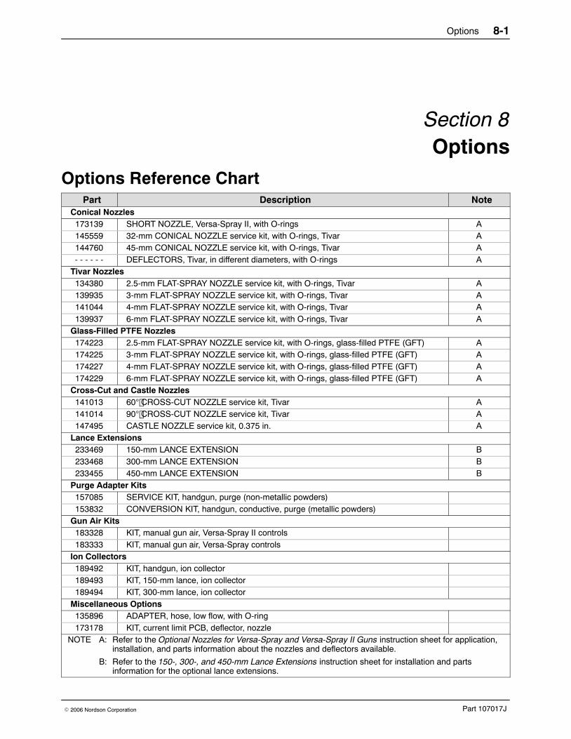
Section 8Options
Options Reference Chart Part Description Note
Conical Nozzles173139 SHORT NOZZLE, Versa-Spray II, with O-rings A145559 32-mm CONICAL NOZZLE service kit, with O-rings, Tivar A144760 45-mm CONICAL NOZZLE service kit, with O-rings, Tivar A- - - - - - DEFLECTORS, Tivar, in different diameters, with O-rings A
Tivar Nozzles134380 2.5-mm FLAT-SPRAY NOZZLE service kit, with O-rings, Tivar A139935 3-mm FLAT-SPRAY NOZZLE service kit, with O-rings, Tivar A141044 4-mm FLAT-SPRAY NOZZLE service kit, with O-rings, Tivar A139937 6-mm FLAT-SPRAY NOZZLE service kit, with O-rings, Tivar A
Glass-Filled PTFE Nozzles174223 2.5-mm FLAT-SPRAY NOZZLE service kit, with O-rings, glass-filled PTFE (GFT) A174225 3-mm FLAT-SPRAY NOZZLE service kit, with O-rings, glass-filled PTFE (GFT) A174227 4-mm FLAT-SPRAY NOZZLE service kit, with O-rings, glass-filled PTFE (GFT) A174229 6-mm FLAT-SPRAY NOZZLE service kit, with O-rings, glass-filled PTFE (GFT) A
Cross-Cut and Castle Nozzles141013 60 CROSS-CUT NOZZLE service kit, Tivar A141014 90 CROSS-CUT NOZZLE service kit, Tivar A147495 CASTLE NOZZLE service kit, 0.375 in. A
Lance Extensions233469 150-mm LANCE EXTENSION B233468 300-mm LANCE EXTENSION B233455 450-mm LANCE EXTENSION B
Purge Adapter Kits157085 SERVICE KIT, handgun, purge (non-metallic powders)153832 CONVERSION KIT, handgun, conductive, purge (metallic powders)
Gun Air Kits183328 KIT, manual gun air, Versa-Spray II controls183333 KIT, manual gun air, Versa-Spray controls
Ion Collectors189492 KIT, handgun, ion collector189493 KIT, 150-mm lance, ion collector189494 KIT, 300-mm lance, ion collector
Miscellaneous Options135896 ADAPTER, hose, low flow, with O-ring173178 KIT, current limit PCB, deflector, nozzle
NOTE A: Refer to the Optional Nozzles for Versa-Spray and Versa-Spray II Guns instruction sheet for application,installation, and parts information about the nozzles and deflectors available.
B: Refer to the 150-, 300-, and 450-mm Lance Extensions instruction sheet for installation and partsinformation for the optional lance extensions.

Options8-2
Part 107017J � 2006 Nordson Corporation
Purge Adapter Kits
Purge Adapter Kit for Non-Metallic Powder CoatingsSee Figure 8-1.
Item Part Description Quantity Note— 157085 SERVICE KIT, handgun, purge, Versa-Spray,
non-conductive1
1 153830 � PANEL, control, purge 12 157094 � ADAPTER, purge, Versa-Spray 13 - - - - - - � � ADAPTER, purge, inlet 14 - - - - - - � � ADAPTER, purge, outlet 15 940163 � � O-RING, silicone, 0.625 x 0.750 x 0.062 in. 16 1021472 � � VALVE, check, 6-mm tube x 6-mm tube 17 900586 � � TUBING, polyurethane, 6-mm OD x
4-mm ID, blueAR
8 183456 � � FITTING, swivel, elbow, 6-mm tubing x1/8-in. BPST
1
AR: As Required
1400192A
1
2
5
3
47
6
8
Figure 8-1 Purge Adapter Kit for Non-Metallic Powder Coatings

Options 8-3
Part 107017J� 2006 Nordson Corporation
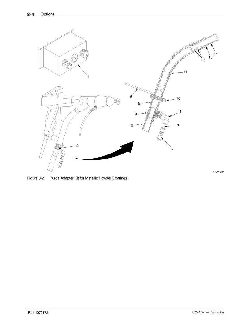
Purge Adapter Kit for Metallic Powder CoatingsSee Figure 8-2.
Item Part Description Quantity Note— 153832 CONVERSION KIT, handgun, purge, Versa-Spray,
conductive1
1 153830 � PANEL, control, purge 12 157094 � ADAPTER, purge, Versa-Spray 13 - - - - - - � � ADAPTER, purge, inlet 14 - - - - - - � � ADAPTER, purge, outlet 15 940163 � � O-RING, silicone, 0.625 x 0.750 x 0.062 in. 16 1021472 � � VALVE, check, 6-mm tube x 6-mm tube 17 900586 � � TUBING, polyurethane, 6-mm OD x
4-mm ID, blueAR
8 183456 � � FITTING, swivel, elbow, 6-mm tubing x1/8-in. BPST
1
9 156204 � BRACKET, hose, purge adapter 110 140290 � CLAMP, tubing, worm drive, 0.906−0.500 in. 111 156203 � TUBE, inlet, conductive PTFE 112 940142 � O-RING, silicone, 0.500 x 0.625 x 0.063 in. 213 940163 � O-RING, silicone, 0.625 x 0.750 x 0.063 in. 114 972368 � ADAPTER, conductive, inlet tube 1
AR: As Required
Options8-4
Part 107017J � 2006 Nordson Corporation
1400193A
1
3
9
8
11
10
13
4
5
14
12
7
62
Figure 8-2 Purge Adapter Kit for Metallic Powder Coatings
Options 8-5
Part 107017J� 2006 Nordson Corporation
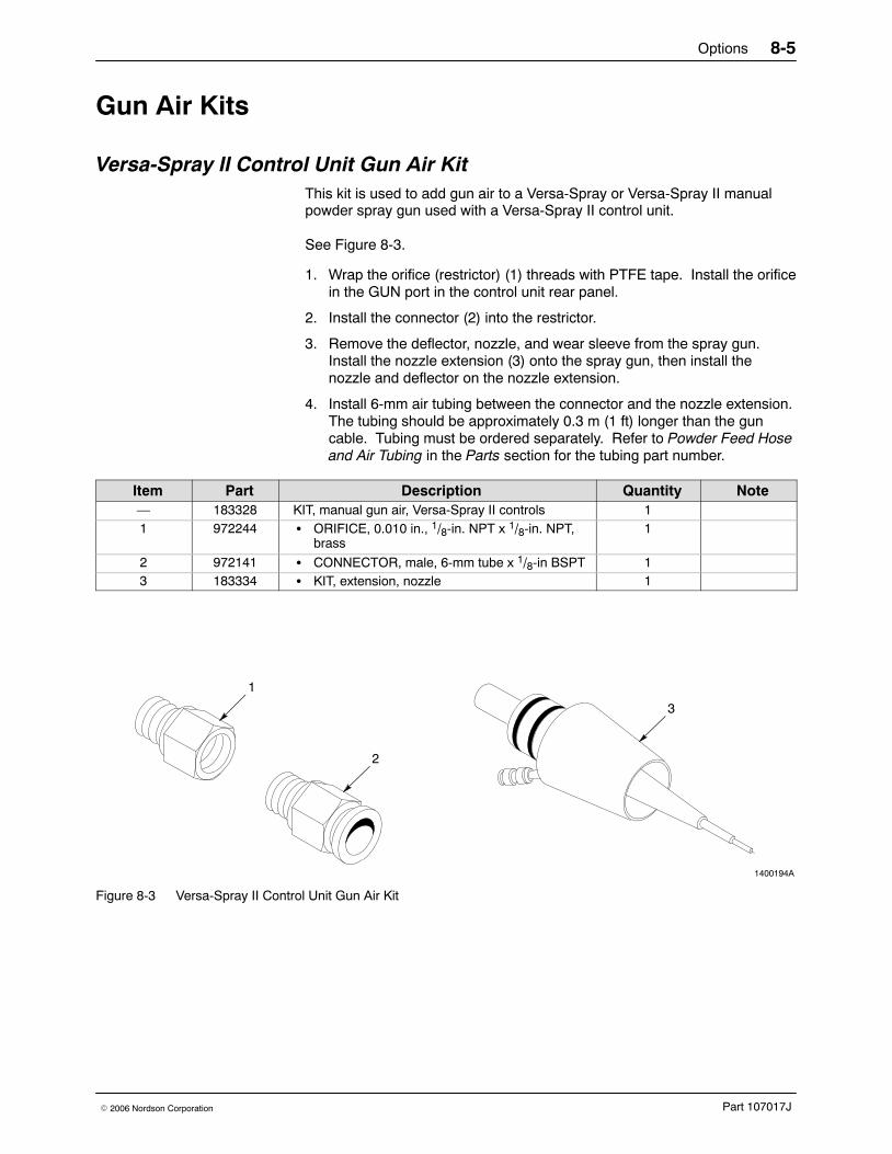
Gun Air Kits
Versa-Spray II Control Unit Gun Air KitThis kit is used to add gun air to a Versa-Spray or Versa-Spray II manualpowder spray gun used with a Versa-Spray II control unit.
See Figure 8-3.
1. Wrap the orifice (restrictor) (1) threads with PTFE tape. Install the orificein the GUN port in the control unit rear panel.
2. Install the connector (2) into the restrictor.
3. Remove the deflector, nozzle, and wear sleeve from the spray gun.Install the nozzle extension (3) onto the spray gun, then install thenozzle and deflector on the nozzle extension.
4. Install 6-mm air tubing between the connector and the nozzle extension.The tubing should be approximately 0.3 m (1 ft) longer than the guncable. Tubing must be ordered separately. Refer to Powder Feed Hoseand Air Tubing in the Parts section for the tubing part number.
Item Part Description Quantity Note— 183328 KIT, manual gun air, Versa-Spray II controls 11 972244 � ORIFICE, 0.010 in., 1/8-in. NPT x 1/8-in. NPT,
brass1
2 972141 � CONNECTOR, male, 6-mm tube x 1/8-in BSPT 13 183334 � KIT, extension, nozzle 1
1400194A
1
3
2
Figure 8-3 Versa-Spray II Control Unit Gun Air Kit
Options8-6
Part 107017J � 2006 Nordson Corporation
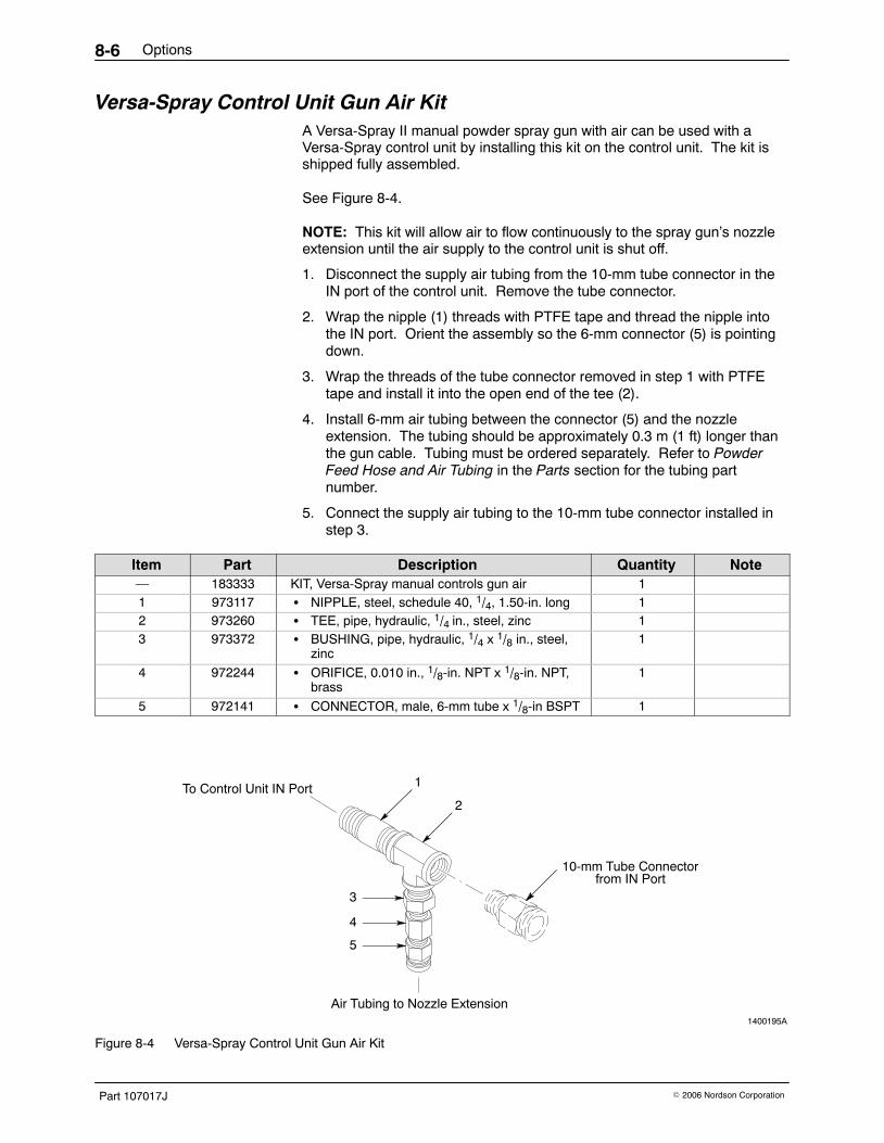
Versa-Spray Control Unit Gun Air Kit A Versa-Spray II manual powder spray gun with air can be used with aVersa-Spray control unit by installing this kit on the control unit. The kit isshipped fully assembled.
See Figure 8-4.
NOTE: This kit will allow air to flow continuously to the spray gun’s nozzleextension until the air supply to the control unit is shut off.
1. Disconnect the supply air tubing from the 10-mm tube connector in theIN port of the control unit. Remove the tube connector.
2. Wrap the nipple (1) threads with PTFE tape and thread the nipple intothe IN port. Orient the assembly so the 6-mm connector (5) is pointingdown.
3. Wrap the threads of the tube connector removed in step 1 with PTFEtape and install it into the open end of the tee (2).
4. Install 6-mm air tubing between the connector (5) and the nozzleextension. The tubing should be approximately 0.3 m (1 ft) longer thanthe gun cable. Tubing must be ordered separately. Refer to PowderFeed Hose and Air Tubing in the Parts section for the tubing partnumber.
5. Connect the supply air tubing to the 10-mm tube connector installed instep 3.
Item Part Description Quantity Note— 183333 KIT, Versa-Spray manual controls gun air 11 973117 � NIPPLE, steel, schedule 40, 1/4, 1.50-in. long 12 973260 � TEE, pipe, hydraulic, 1/4 in., steel, zinc 13 973372 � BUSHING, pipe, hydraulic, 1/4 x 1/8 in., steel,
zinc1
4 972244 � ORIFICE, 0.010 in., 1/8-in. NPT x 1/8-in. NPT,brass
1
5 972141 � CONNECTOR, male, 6-mm tube x 1/8-in BSPT 1
1400195A
To Control Unit IN Port
Air Tubing to Nozzle Extension
10-mm Tube Connectorfrom IN Port
1
2
3
4
5
Figure 8-4 Versa-Spray Control Unit Gun Air Kit
Options 8-7
Part 107017J� 2006 Nordson Corporation
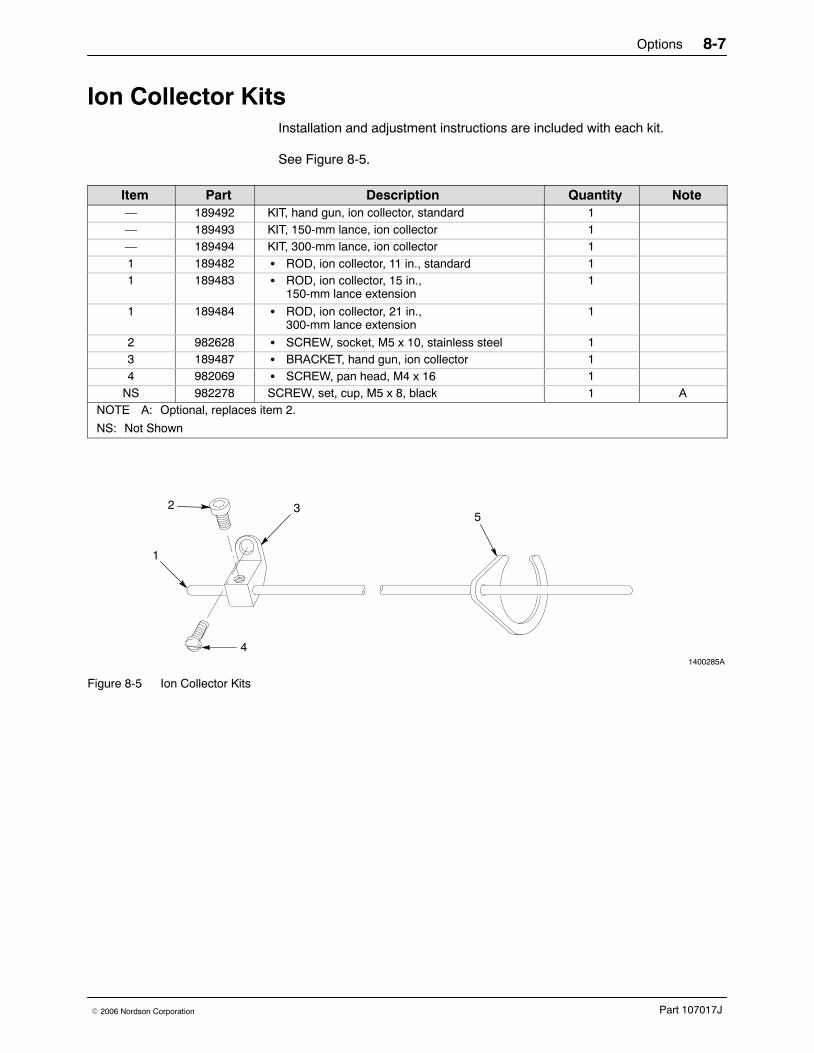
Ion Collector KitsInstallation and adjustment instructions are included with each kit.
See Figure 8-5.
Item Part Description Quantity Note— 189492 KIT, hand gun, ion collector, standard 1— 189493 KIT, 150-mm lance, ion collector 1— 189494 KIT, 300-mm lance, ion collector 11 189482 � ROD, ion collector, 11 in., standard 11 189483 � ROD, ion collector, 15 in.,
150-mm lance extension1
1 189484 � ROD, ion collector, 21 in.,300-mm lance extension
1
2 982628 � SCREW, socket, M5 x 10, stainless steel 13 189487 � BRACKET, hand gun, ion collector 14 982069 � SCREW, pan head, M4 x 16 1
NS 982278 SCREW, set, cup, M5 x 8, black 1 ANOTE A: Optional, replaces item 2.
NS: Not Shown
1400285A
1
25
3
4
Figure 8-5 Ion Collector Kits

Options8-8
Part 107017J � 2006 Nordson Corporation
Miscellaneous Options
Low-Flow Hose Adapter See Figure 8-6.
Item Part Description Quantity Note1 135896 ADAPTER, hose, low flow, with O-ring 12 940163 � O-RING, silicone, 0.625 x 0.750 x 0.063 in. 1
1400198A
1
2
Figure 8-6 Low-Flow Hose Adapter for 3/8-in. ID Hose

Options 8-9
Part 107017J� 2006 Nordson Corporation
Versa-Spray Control Unit and Manual Gun Upgrade KitThis kit is used to upgrade a Versa-Spray control unit and manual powderspray gun. It adds the AFC function to the control unit, and theVersa-Spray II conical nozzle and deflector to the manual powder spraygun.
See Figure 8-7.
Item Part Description Quantity Note— 173178 KIT, current limit PCB, deflector, nozzle 11 - - - - - - � CIRCUIT BOARD, current limit, Versa-Spray,
IPS1
2 173139 � NOZZLE, short, Versa-Spray II, with O-ring 13 173138 � DEFLECTOR, 19 mm, Versa-Spray II, with
O-ring1
NS 108815 � INSTRUCTIONS, AFC control kit installation 1NS: Not Shown
1400199A
12
3
Figure 8-7 Versa-Spray Control Unit and Manual Gun Upgrade Kit