verification of railway interlocking tables using coloured petri nets*
TRANSCRIPT

Verification of Railway Interlocking Tables using ColouredPetri Nets�
Somsak Vanit-Anunchai
School of Telecommunication Engineering
Institute of Engineering, Suranaree University of Technology
Muang, Nakhon Ratchasima 30000, Thailand
Email: [email protected]
Abstract. A functional specification for railway signalling systems called “control table” plays
a vital role in the signalling design and installation processes. Control tables are the tabular
representation specifying the routes, on which the passage of the train is allowed. Associated
with the route, the states and actions of all related signalling equipment are also specified.
Although various software tools are available for generating, editing and checking the control
tables, there are still some drawbacks. Firstly, those tools are usually bound up with the a specific
railway company. Secondly, each railway company has its own operating rules and regulations
that control tables need to comply with. The control tables that are automatically generated and
verified still require manual inspection by the railway signal engineer. This checking process is
very labor intensive and prone to errors. To detect and eliminate errors, we propose to formally
model and analyse the interlocking tables using CPN Tools. Our CPN model comprises two
parts: Signalling Layout model and Interlocking model. We use ML functions on arc inscription
in the Interlocking model. These ML functions can be generated directly from the content of
the control table using Extensible Stylesheet Language Transformations (XSLT). Thus our CPN
model can be easily adapted and reused and CPN models of other control tables can be rapidly
built. Finally some experimental results are discussed to convince us of the correctness of our
CPN model and the control tables.
Keywords: Control Tables, Interlocking Tables, Railway Signalling Systems, Coloured Petri
Nets, State space Analysis
1 Introduction
Currently the State Railway of Thailand (SRT) has been undertaking several railway sig-nalling projects involving either improvement of the existing signalling systems or expansionof the existing railway lines. During the whole process of designing, installing and testing thesignalling system, “Interlocking Tables” or “Control Tables” play a vital role in every stage.The control table is a tabular representation specifying how the trains move together with therequired states and actions of all related equipment. This important document also acts as anagreement between the railway administrators and the contractors. Many signalling contrac-tors have software tools for editing, generating and verifying the control tables. Usually thecontrol table generated by a software tool is bound up with a specific railway company. ButSRT has its own operating regulations, requirements and signalling principles that controltables need to comply with. Thus after the control tables are designed and checked by thecontractors, they need to be rechecked by SRT’s signal engineers. Now SRT signal engineersmanually inspect the submitted control tables without any software tools. Thus the checkingprocess is very slow, labour intensive and prone to errors. In order to assist their inspection,detect and rectify errors rapidly, we propose to formally model and analyze the control ta-bles using CPN Tools [12]. Because SRT’s signalling projects involve hundreds of Interlocking�
Supported by National Research Council of Thailand Grant no. PorKor/2551-153
139

systems, we wish to study how to rapidly re-build the CPN model of the control tables for
other Interlocking systems. Our counter part, SRT’s signal engineers, believe that the signal
engineers should build, maintain and modify the CPN models of control tables themselves
due to the details and complication of the problem. Thus CPN Tools is a good candidate
because its graphical language and the user interface are easy to use.
The contribution of this paper is two folds. Firstly, the Phanthong’s control table is mod-
elled and verified against its desired property. Secondly, we discuss design decision on how
to create a CPN model of a control table that can be easily adapted and reused for other
control tables. In particular, we propose to standardize the format of control tables using
XML and using XSLT to transform the content of the control table to ML functions used in
the CPN model. Thus the signal engineers who follow our methodology do not need to be a
programming expert in C, Java or ML.
The rest of this paper is organised as follows. Section 2 briefly explains the concept of
railway signalling system and control tables. Section 3 discusses related work. Section 4 defines
the scope of work by discussing assumptions, modelling approach and model structure. The
CPN model of Panthong control table is illustrated in Section 5 and 6. Section 7 discusses
our analysis results. Conclusion and Future work are presented in Section 8.
2 Railway Signalling Systems and Control Tables
2.1 Signalling Systems
In general the railway lines are basically divided into sections. To avoid collision, only one
train is allowed in one section at a time. The train can enter or leave the section when the
driver receives authorization from a signalman via a signal indicator. Before the signalman
issues the authorization, he needs to ensure that no object blocks the passage of the train.
SRT’s regulation divides the section into two categories: between two stations and within
the station area. The section between two railway stations, which involves two signalmen,
is called “block section”. Usually railway companies have a strict procedure how to admit
trains into a block section. To prevent human error, which often leads to collisions, the strict
operation on a block section is controlled by an equipment called “Block Instrument”. The
Block Instrument has 3 possible states. It is Normal when there is no train in the block section
and no one requests block possession. It is in Going state when the permission for the block
possession is given to the outgoing train. It is in Coming state when the permission for the
block possession is given to the incoming train.
Figure 1 shows the signalling layout of a small station named “Panthong”. It comprises a
collection of railway tracks and signalling equipment such as track circuits, points and signals.
Main signals are classified into three types:, warner, home and starter signals. SRT defines
that the station area is between two home signals (signal no.3 and signal no.4). Each piece of
signalling equipment has an identification number and holds a certain state as follows.
Track Circuits A track Circuit is an electrical devices used to detect the presence of a train.
A track circuit (e.g. 42T, 2T) is either cleared indicating no train on the track or occupiedindicating the possible1 presence of a train.
1 When the track circuit fails, its state is occupied even if there is no train.
140

1T
3T
9
T
10
3T
24
T
16
T
42
T
41
T2
3T
15
T
10
4T
4T
2T
8T
Fig. 1. Signalling layout of the Panthong Station
141

Warner signals A warner signal (e.g. 1, 2) has two aspects: yellow or green. It informs
drivers about the status of the next signal.
Home signals A home signal (e.g. 3, 4) has three aspects: red or yellow or green.
It displays red when forbidding the train enter the station area.
It displays yellow giving the driver authorities to move the train into the station area and
prepare to stop at the next signal.
It displays green giving the driver authorities to move the train passing the station and
enter the next block section.
Starter signals A starter (e.g. 16, 24, 15, 23) has two aspects: red or green.
It displays red when forbidding the train to enter the block section.
It displays green when giving the driver authorities to move the train into the block section.
Point A point (e.g. 103, 104) or railway switch or turnout is a mechanical installation used
to guide a train from one track to another. A point usually has a straight through track called
main line and a diverging track called loop line. A point is right-hand when a moving train
from a joint track diverges to the right of the straight track. Similarly a left-hand point has
the diverging track on the left of the straight line. When a point diverges the train, it is in
reverse position. When a point lets the train move straight through, it is in normal position.
When the interlocking prevents a point from changing position, the point is locked.
2.2 Control Tables
A collection of track circuits along the reserved section is called “route”. An entry signal shall
be cleared to let the train enter the route. Although the request to clear the entry signal is
issued by the signalman, the route entry permission is decided by the interlocking system
using safety rules and control methods specified in the agreed control tables. Table 1 and 2
are the control tables for Panthong station of which signalling layout is shown in Fig. 1. Data
in the first column, “From”, is the route identifications which are labeled by the entry signal:
3(1); 3(2); 4(1); 4(2); 15; 16; 23 and 24. Each row in the tables represents the requirement
how to set and release each route. For example, route 3(2) comprises the track circuits 3T,
9T, 103T, 16T, 42T, 15T and requires that the points 103 and 104 are in normal position.
Routes 3(1) and 3(2) distinguish that behind signal 3 two routes are possible. Similar rule
applies to routes 4(1) and 4(2).
Different Interlocking systems from different manufacturers may have different control
methods. However there are four basic control methods widely accepted and used among
railway companies.
Route locking Route setting involves a collection of adjacent track circuits, points and
signals. To assure the safety, firstly, the interlocking system verifies that the route does not
conflict with other routes previously set. The column “Requires Route Normal” shows conflict
routes. A route cannot be set if any conflict routes have been set and not yet released. For
route 3(2) the conflict routes are 16, 23, 24, 4(1), 4(2) and 3(1). Secondly, the points along the
route are locked in the correct positions. If the related points are not in the correct positions,
the controller will attempt to set and lock them in the correct positions. Thirdly, the track
142

Table 1. A control table for Panthong station (part 1:Route locking)
TC CLEAR OCC FOR
2 4 Y 4 AT R# 3 AT Y# OR G#G
AT TIME OF CLEARING ONLY
OR TIME
CLEAR
ROUTE
INTERLOCKING CONTROL
REQUIRES TC
ASPECT
# O G#G
SIGNAL AHEAD
REQUIRES
1 3
From To
REQUIRES SET & LOCKS POINTS
NORMALROUTE NORMAL NORMAL REVERSE
KEYLOCK
Y 3 AT R#
103,104
104,103
Y 16 AT R#
BLOCK24T,103T,9T,3T,1T,TOLG24 DOWN
SECTION16,3(1),3(2)
BLOCK103,104
24,3(1),3(2) G 16T,103T,9T,3T,1T,TOLSECTION
23 UP G 23T,104T,8T,4T,2T,TOL15,4(1),4(2)
BLOCK
42 FOR60 sec24T,103T,9T,3T
15 UP G
201,202, Y+JI 24 AT R#
23,4(1),4(2) 15T,104T,8T,4T,2T,TOL203,204
4215,23,3(1),3(2),4(1)4(2) 24
41 41 FORG 16 AT G# 60 sec
15,23,3(1),3(2),4(2)4(1) 1615 AT G#
41 41 FOR103,104
3T,9T,103T,16T,42T,15T,104T,8T,4T 60 sec
4 AT Y# OR G#
203,204103,104
42 42 FOR3T,9T,103T,24T,41T,23T,104T,8T,4T
G
60 sec3(2) 15
16,24,4(1),4(2),3(2)
16,24,4(1),4(2),3(1)
16 DOWN
3(1)
SECTION
BLOCK
23
4T,8T,104T,23T,41T,
104,103
104,103
104,103
4T,8T,104T,15T,42T,16T,103T,9T,3T
201,202, Y+JI 23 AT R#
Y 15 AT R# G
103,104
SECTIONBLOCK
Table 2. A control table for Panthong station (part 2:Approach locking)
WHEN SIGNAL CLEARED &
AND
RELEASEFrom TO
APPROACH LOCKED
ORTC OCC
TC OCC
TC OCC
1 3
& CLEAREmergency
OR
CLEAR REMARKS
AND / OR
AFTER
ROUTE RELEASED BYROUTE
CONTROL
Notes
TC
REPEAT 4
REPEAT 3WARNER
TIME
WARNER2 4
1 DOWN BLOCK NOTSETDOWN XING BOOM DOWN
1 DOWN BLOCK NOTSETDOWN XING BOOM DOWN
2 UP BLOCK NOTSETUP XING BOOM DOWN
2 UP BLOCK NOTSETUP XING BOOM DOWN
42T UP BLOCK SETUP XING BOOM DOWN
41T UP BLOCK SETUP XING BOOM DOWN
42T DOWN BLOCK SET
23 240s41T103T120s
16 DOWN
3(1) 3T,9TREPEAT 4
3(2) 15 3T,9T 103T 42T 240s
4(1) 16 120s 4T,8T 104T
120s
4(2) 24
15 UP 2 240s120s 15T,104T, 4BLOCK 8T
23 UPSECTION
2 240s120s 23T,104T,BLOCK
48T
SECTION240s120s 16T,103T, 3 1
4T,8T 104T 41T 240s120s
42T 240s
DOWN XING BOOM DOWN
41T DOWN BLOCK SETDOWN XING BOOM DOWN
19T
, ,BLOCK 9T
SECTION240s120s 24T,103T, 324 DOWN
BLOCKSECTION
circuits along the required route are all cleared or unoccupied so that nothing obstructs thepassage of the train. Then the entry signal can be cleared (showing yellow or green). Thehome signal will be green if the exit signal of the route shows green too. For example the exit(starter) signal of the route 3(2) is 15. If starter signal 15 shows green and route 3(2) is set,the home signal 3 will show green.
Approach locking After a route is set; the points are locked; and the entry signal is cleared,if the track circuit in front of (approaching) the entry signal is occupied, then the signalmancannot cancel the route and the entry signal by the normal procedure. Approach lockingprevents the train driver from the sudden change of signal aspect from green or yellow to red.
143

Column 3 in Table 2, “APPROACH LOCKED WHEN SIGNAL CLEARED & TC OCC”,presents locking when the approach track circuit is occupied. For example, route 3(2) willbe approach locked if the route is set and track 1T is occupied. The approach locking alsohappens after the signal is cleared longer than 2 minutes.
Route released By the passage of the train, the reserved route is automatically released.Column “Route Released by” in Table 2 presents route released mechanism for the signallinglayout in Fig. 1. Route 3(2) will be released when track 3T, 9T is cleared; track 103T isoccupied and then cleared; and track 42T is occupied. The reserved route can be emergencyreleased but the release action will be delayed for 4 minute after the signalman issues “emer-gency route released” command.
Flank protection The equipments within the surrounding area of the reserved route thatmay cause an accident shall be protected even if no train is expected to pass such a signal orsuch points. For example points should be in such positions that they do not give immediateaccess to the route. The last two columns of Table 2 presents an example of flank protection.For route 3(2), the track 41T, which is not in the route 3(2), shall be unoccupied. If it isoccupied, the object on the track 41T should stand still. This condition is implied if the track41T is occupied longer than 1 minute.
3 Related Work
Fokkink and Hollingshead [7] provided a perspective that can classify the research work re-garding verification of railway signaling systems. According to [7] the railway signalling systemis divided into three layers: infrastructure, interlocking and logistic layers. All layers must pro-vide safety for railway operation. The infrastructure layer involves objects or equipment usedin the yard. The work in this category, for instance [1,3,6,13], ties closely with manufacturer’sproducts. The logistic layer involves human operation and train scheduling which aims at effi-ciency and deadlock free. It involves the operation of whole railway network (e.g. [9,11]) thusthe state explosion problem is often encountered. The interlocking layer provides the interfacebetween the logistic and infrastructure layers. It prevents us from accidents caused by humanerrors or equipment failures. The work in this category such as [10,15,16] models the controltables and verify it against the safety regulations and signalling principles.
Hansen [10] presented a VDM (Vienna Development Method) model of a railway interlock-ing system, and validated it through simulation using ML. The work focuses on the principlesand concepts of Danish systems rather than a particular interlocking system. He also pointedout that Interlocking systems from other countries may be different from the Interlocking de-scribed in [10]. Boralv [1] and Peterson [13] constructed interlocking programs using a speciallanguage called STERNOL, which was developed by ADTranz in Sweden, and verified theinterlocking programs using NP-Tools.
Because relay interlocking and computer interlocking [3] are designed based on ladderlogic diagrams, Fokkink and Hollingshead [7] proposed to convert ladder logic diagrams toBoolean formulae. Then they applied a theorem prover to verify these Boolean formulae.
Winter et al [14] proposed to create two formal models during the design process of in-terlockings. One is the formal model of the Signalling Principles called Principle model. The
144

other is the formal model of the functional specification for a specific track-layout called Inter-locking model. The Control Tables are translated into a Interlocking model and then checkedagainst the Principle model. At first she used CSP (Communicating Sequential Processes) asa modelling language but later found that the CSP models of the interlocking system and thesignalling principle are difficult to understand and validate. Thus [16] used Abstract StateMachine (ASM) [8] notation to model the semantic of control tables. The ASM model wasthen automatically converted to NuSMV code [4] while the safety properties were modeledin CTL (Computation Tree Logic). Finally [15] they modelled the safety properties in ASMand then translated both ASM models into the NP Prover tool [1] in order to compare theperformance between NuSMV and NP-tool. They discovered that if the track layout wasdivided into smaller segments for verification, the NuSMV outperformed the NP-Tool. Ourwork shares the same goal to [1, 7, 13–16] but our tools and signalling principles differ fromtheir.
Hagalisletto et al [9] demonstrated how to construct and refine models of railway using acomponent-oriented approach. They modelled atomic nets, such as track circuits and turnouts,using Coloured Petri Nets. Although atomic nets were created using Design/CPN, the modelswere simulated [2] using Maude [5] due to the state explosion problem. Even though our CPNmodels of each piece of equipment, such as track circuits, was inspired by [9], our work aimsat the interlocking table of one station while [9] involved the logistic layer and the wholerailway network.
4 CPN Model of the Panthong’s Control Table - Overview
Currently SRT has been undertaking track doubling projects which need to verify hundredsof interlocking systems. Thus it is necessary to seek out a modelling approach to rapidlybuild and verify these control tables. An existing control table of a single track station named“Panthong” was selected as a modelling exercise because its new control table with doubletrack is being designed by a contractor. We wish to upgrade our CPN model for the doubletrack station to verify the new control table in the near future.
4.1 Modelling Scope and Assumptions
To reduce the complexity of the model as well as the state explosion problem which has beenreported by a number of researchers [9,16] who investigated the similar problems, we need tomake the following assumptions regarding train movement and signalling operations:
1. We assume that a train has no length and it occupies one track at a time. The trainmoves in only one direction. Train shunting is not considered.
2. We assume the trains running at the same speed.3. Our model does not include the auxiliary signals such as Call-on, Shunting and Junction
indicators.4. Our model does not include timers. However we use time stamps when modelling the
trains moving along the track. This implies moving a train takes longer than other actionsin the system. For example the train must not move through a track circuit so fast that theinterlocking cannot detect the presence of the train.
5. Our model does not include emergency route release, emergency point operation.6. Normally the signalling system provides a safety mechanism when equipment fails. Our
model does not consider when equipment fails.
145

7. Our model does not include level crossings.
8. Our model includes high level abstraction of block systems but we do not model their
operations in detail.
9. Our model does not include flank protections.
10. The train drivers strictly obey the signals.
4.2 Modelling Approach and Model Structure
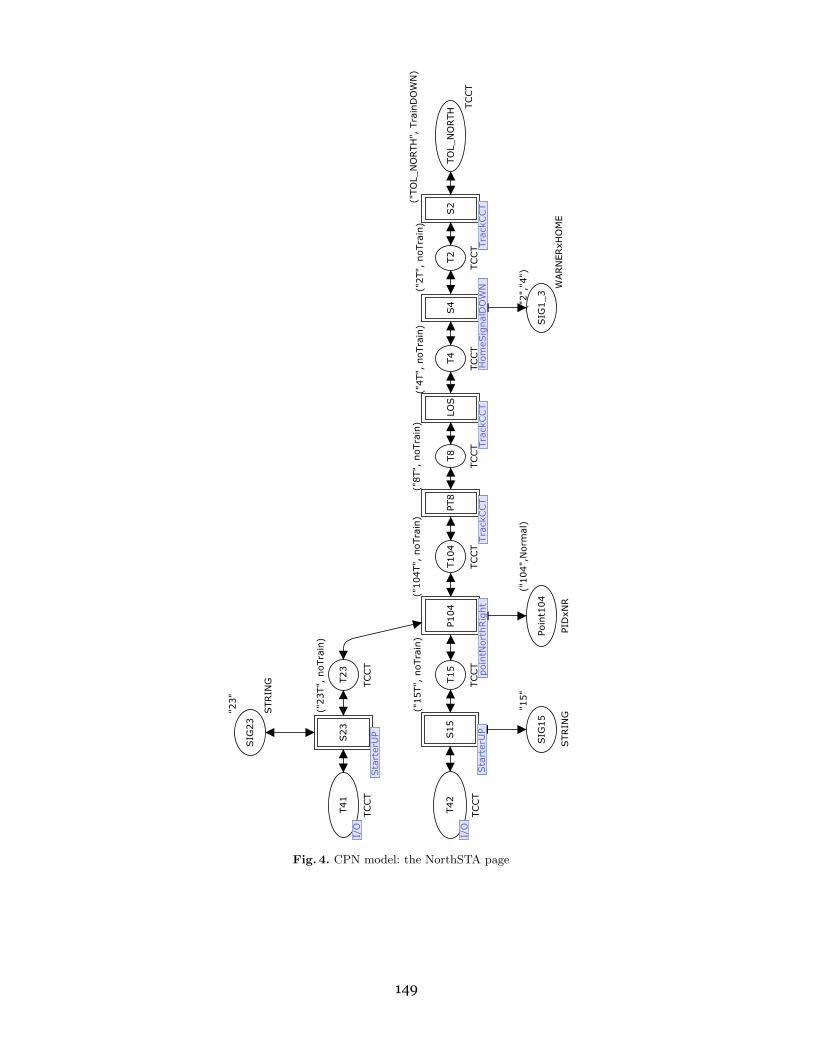
Our CPN model comprises 2 parts: Signalling Layout and Interlocking. The Signalling Layoutpart shown in Fig. 3 and Fig. 4 represents the system we wish to control. The Interlocking part
represents the interlocking controller. CPN models in Fig. 3 and Fig.4 mimic the signalling
plan of Panthong station (Fig.1). It comprises three kinds of CPN modules modelling wayside
equipment of which functions and states are described in Section 2.1. The CPN model in Fig. 3
and Fig. 4 provides not only geographic information how each way side equipment is connected
to each other but also the ability to simulate trains moving along the tracks. Basically our
CPN model includes three kinds of the train movements:
a) Train movement between two consecutive track circuits.
b) Trains passing a signal.
c) Trains passing a point.
Comparing with the signalling layout in Fig.1 our model does not include the third loop
line because no track circuit is installed there. But we model the key lock of manual operating
points and de-railers.
The Interlocking part comprises three CPN pages: UserCommand, RouteSetting (Fig.
6) and RouteReleased. They model point setting, route locking, signal clearing and route
release functions as specified in the control table and described in Section 2.2. Unlike [15] that
does not include the functionality of approach locking (to avoid the state explosion problem),
our CPN model does include the approach locking function. Even though the control table
of each railway station has different contents, the functionalities: route locking; approach
locking; route release; and flank protection are essentially the same. Attempting to create a
generic interlocking model, we extract the content of the control table and code them into ML
functions which are used in arc inscriptions. To model control tables of other railway stations
we simply change the content of the ML functions while using the same CPN models of the
Interlocking part.
Next we attempt to create these ML functions automatically as illustrated in Fig. 2. In
previous projects contractors submitted the control tables in Microsoft-Excel to SRT. Instead
of Excel, we encourage SRT to maintain the control table in XML format. As shown in Fig.
2 the control table in Microsoft-Excel is transformed to XML. Then it is transformed to ML
functions using Extensible Stylesheet Language Transformations (XSLT). All operations are
done using Microsoft-Excel and Microsoft-Word version 7.
5 The CPN Model of the Signalling Layout
The top layer of our CPN model, named SouthSTA (Fig. 3), mimics the signalling layout of
Panthong’s southern section. It comprises a sequence of places, T1, T3, T9, T103, T16, T24,T41 and T42. Each place, typed by TCCT, represents a track circuit storing the track circuit
number and its state. TCCT is defined in line 4 of Listing 1.1 as a product comprising Track
146

Excel XML file WordExcel file
XSTL file
SML file
ControlTable
Transform
MLfunctions
Easy to editXSD file
XMLSchema
Fig. 2. Transformation of the control table to ML functions using XSLT
number and Train Description (TD). Line 2 of Listing 1.1 defines TD as a colour set repre-senting states of a track circuit: unoccupied (noTrain); occupied by a train moving awayfrom Bangkok (TrainUP); and occupied by a train moving toward Bangkok (TrainDOWN).Place TOL SOUTH (Train-on-line) models the track section2 between Panthong and the adja-cent station in the south3. The SouthSTA is linked to NorthSTA page (Fig. 4) which modelsthe northern section of the station. Besides signalling layout, SouthSTA page also includessubstitution transitions UserRequestBlock and UserRequestRoute modelling the actions ofblock setting and route setting by the signalman. When approach locking does not occur, thesignalman can cancel the route setting. This route cancel command is modelled by a token inthe fusion place RouteCancel. Substitution transitions S1, LOS and PT9 linked to TrackCCTmodel the passage of the train between two adjacent track circuits. Substitution transition S3linked to HomeSignalUP page (Fig. 5) models the passage of the train when passing the homesignal no.3. Similarly, substitution transitions S16 and S24, both linked to StarterDOWN pagemodel the passage of the train when passing the starter signals no. 16 and 24. We do notneed to model the train passing a warner signal. Because the warner has no red signal signaland it cannot stop the train. It acts as a repeater of the home signal. Its aspect depends onthe aspect of the home signal. Thus we model warner signal no. 1 together with home signalno. 3 in substitution transition S3. Substitution transition P103, linked to PointSouthLeftpage models the passage of the train when passing the point no. 103. Due to space limit, wechoose to explains a CPN subpage named HomeSignalUP because PointSouthLeft page istoo complex and HomeSignalUP is similar to StarterDOWN and TrackCCT pages.
HomeSignalUP page When a train passes the home signal, two signals’ aspects returnto the normal states. The warner signal returns to yellow and the home signal returns tored. HomeSignalUP page (Fig. 5) models these aspect restorations. The HomeSignalUP page isreused at other locations thus it needs an identification place to identify the signal numbers.For example, place SIG1 3 in Fig. 3 links to place WarnerHome in Fig. 5. Place SIG1 3 andWarnerHome are typed by WARNERxHOME which is defined in line 6 of listing 1.1 as a product oftwo strings that are the numbers of the warner and home signals. Place ApproachLock in Fig.5 is used to ensure that the train will not pass the signal post before the approach lockingtakes place. We defer the explanation about places SIGNAL POOL and TrackPool to section6.1.
2 No track circuit is installed at this location.3 South or down means toward Bangkok, north or up means away from Bangkok.
147

Use
rReq
ues
tsBlo
ck
Blo
ckSet
Nort
hSTA
Nort
hSTA
Key
Lock
4
Key
lock
s
Key
Lock
2
Key
lock
s
Key
Lock
1
Key
lock
s
Key
Lock
3
Key
lock
s
Use
rReq
ues
tRoute
Use
rCom
man
d
PT9
Tra
ckCCT
S16
Sta
rter
Dow
n
S24
Sta
rter
Dow
n
S1
Tra
ckCCT
P103
poin
tSouth
Left
S3
Hom
eSig
nal
UP
SIG
24
"24"
STRIN
G
SIG
16"1
6"
STRIN
G
SIG
1_3("1",
"3")
WARN
ERxH
OM
E
Blo
ckReq
ues
t
BLO
CK
K204
"204"
STRIN
G
K202
"202"
STRIN
G
K201
"201"
STRIN
G
K203
"203"
STRIN
G
Poin
t103
("103",
Norm
al)
PID
xNR
Route
Can
cel
Fusi
on 5
RO
UTE
Route
Req
ues
t
1`"3
(1)"
++
1`"4
(1)"
++
1`"3
(2)"
++
1`"4
(2)"
++
1`"1
6"+
+1`"2
4"+
+1`"1
5"+
+1`"2
3"
RO
UTE
T103
("103T",
noTra
in)
TCCT
T24
("24T",
noTra
in)
TCCT
T16
("16T",
noTra
in)
TCCT
T42
("42T",
noTra
in)
TCCT
T41
("41T",
noTra
in)
TCCT
TO
L_SO
UTH
("TO
L_SO
UTH
", T
rain
UP)
TCCT
T1
("1T",
noTra
in)
TCCT
T3
("3T",
noTra
in)
TCCT
T9
("9T",
noTra
in)
TCCT
Fusi
on 5
Hom
eSig
nal
UP
poin
tSouth
Left
Tra
ckCCT
Sta
rter
Dow
n
Sta
rter
Dow
nTra
ckCCT
Use
rCom
man
d
Key
lock
s
Key
lock
sKey
lock
s
Key
lock
s
Nort
hSTA
Blo
ckSet
LOS
Tra
ckCCT
Tra
ckCCT
Fig. 3. CPN model: the SouthSTA page
148
S2
Tra
ckCCT
S4
Hom
eSig
nal
DO
WN
LOS
Tra
ckCCT
PT8
Tra
ckCCT
P104
poin
tNort
hRig
ht
S15
Sta
rter
UP
S23
Sta
rter
UP
SIG
1_3
("2",
"4")
WARN
ERxH
OM
E
SIG
15
"15"
STRIN
G
SIG
23
"23"
STRIN
G
TO
L_N
ORTH
("TO
L_N
ORTH
", T
rain
DO
WN
)
TCCT
T2
("2T",
noTra
in)
TCCT
T4
("4T",
noTra
in)
TCCT
T8
("8T",
noTra
in)
TCCT
T104
("104T",
noTra
in)
TCCT
Poin
t104
("104",
Norm
al)
PID
xNR
T15
("15T",
noTra
in)
TCCT
T23
("23T",
noTra
in)
TCCT
T42
I/O
TCCT
T41
I/O
TCCT
I/O
I/O
Sta
rter
UP
Sta
rter
UP
poin
tNort
hRig
ht
Tra
ckCCT
Tra
ckCCT
Hom
eSig
nal
DO
WN
Tra
ckCCT
Fig. 4. CPN model: the NorthSTA page
149

Fig. 5. CPN model: the HomeSignalUP Page
Listing 1.1. Declarations1 (∗ Global Dec l a ra t i on s ∗)2 c o l s e t TD = with noTrain | TrainUP | TrainDOWN;
3 var tr ,train_direction:TD;
4 c o l s e t TCCT = product STRING * TD timed;5 c o l s e t TRACK = r eco rd tid:STRING * pos:TD;
6 c o l s e t WARNERxHOME = product STRING * STRING;
7 c o l s e t E = with e;
8 c o l s e t NR = with Normal | Reverse;
9 var pos1:NR;
10 c o l s e t PIDxNR = product STRING * NR;
11 c o l s e t SIG = with G | Y | R;
12 var w,h,s,GYR:SIG;
13 c o l s e t SIGNAL = r eco rd sid:STRING * pos:SIG;
14 var p_id ,tc_id1 ,tc_id2 ,sig_id1 ,sig_id2:STRING;
15 var entry ,dst ,warner ,home ,starter ,block_no:STRING;
16 c o l s e t ROUTE = STRING;
17 var route ,setting_route ,in_route2:ROUTE;
18 c o l s e t ROUTExSIG_ID = product ROUTE * STRING;
19 c o l s e t POINT = r eco rd pid:STRING * pos:NR * lock:BOOL;
20 var point:POINT;
21 c o l s e t BLOCK_POS = with COMING | NORMAL | GOING;
22 var CNG:BLOCK_POS;
23 c o l s e t BLOCK = r eco rd bid:STRING * pos:BLOCK_POS;
24 v a l n =10;
25 var x:BOOL;
26 use "C:/ InitMarkings.sml";
27 use "C:/ FromXSL.sml";
150

The CPN diagrams of HomeSignalDOWN, StarterUP and StarterDOWN pages are very
similar to the HomeSignalUP. We do not fold these pages together because, we think, at the
early stage of the model development, folding will cause confusion. We consider that it is
faster to select and plug in one of the four CPN modules.
6 The CPN Model of the Interlocking
6.1 Fusion Places - Communication channels between the way side equipmentand the interlocking center
This section attempts to explain the CPN model of the interlocking controller according to
the functions specified in the control table. To perform its functions, the controller needs to
know the states of equipment in the system. Five fusion places are used to store the states of
equipment: TrackPool (typed by TRACK - line 5 of of listing 1.1); PointPool (typed by POINT- line 19); SignalPool (typed by SIGNAL - line 13); BlockPool (typed by BLOCK - line 23); and
RouteNormal (typed by ROUTE - line 16). TRACK is defined as a record of track identification
and train description. POINT is defined as record of point identification, its position (Normal
or Reverse) and locking status. SIGNAL is defined as a record of signal identification and
its aspect (green, yellow or red). BLOCK is defined as a record of block identification and its
state (train coming, train going or block normal). Fusion place RouteNormal stores the route
identifications that have not been set.
For example, when a train moves from “TOL SOUTH” to “1T”, substitution transition S1
updates not only place T1 with a token (“1T”, TrainUP) but also place TrackPool with
a token 1‘{tid = “1T”, pos = TrainUP}. It is obvious that the same information has been
stored twice which is bad due to the state explosion problem. A solution to the problem is
that deleting the state of track circuits in each track place (e.g. T1, T3). But we will loose
an ability to view the passage of train in Fig. 3 and 4 which is useful for simulating and
debugging the model. On the other hand, storing a track circuit state twice mimics the real
situation. In the real signalling system, the status of track circuit “1T” is actually kept in
two locations: at a way side box and at the interlocking controller. Putting a token into place
TrackPool can be viewed as the track circuit sending its state to the interlocking center via
the fusion place TrackPool. A similar situation applies to fusion places PointPool.Due to space limit we choose to explain only the RouteSetting page because this page
plays a central role of the interlocking function in the model.
RouteSetting page Figure 6 shows the RouteSetting page which models route setting and
cancelations. Transition SetRoute takes tokens from fusion places TrackPool, PointPool and
RouteNormal, and checks if
1. No conflict route is being set. This models by function require route normal.2. The tracks along the route are unoccupied. This models by function require track clear.3. The related points is set and lock in the required positions. This models by function
require point normal and require point reverse.If all three vital conditions are met, the setting route is reserved. But the signals is not
clear yet, because non-vital conditions such as block status and level crossing booms down
have not yet been proved. At this stage the signalman can cancel the route by putting a route
token into fusion place RouteCancel. The route cancel at this stage is modelled by transition
RouteCancel1. It restores the route identification into fusion place RouteNormal and unlocks
151

Fig. 6. CPN model: the RouteSetting page
related points. Place enable is used to ensure that the interlocking controller will service the
next route request command only after the previous valid command have its route reserved.
After the non-vital conditions are complied, transition ClearSignal clears the related
signals. After route reserved and signal cleared but approach locking has not taken place yet,
the signalman can still cancel the route which is modelled by transition RouteCancel2. This
route cancelation restores the route identification into fusion place RouteNormal, unlocks re-
lated points and returns the state of all related signals to normal. Without route cancellation,
at this stage the interlocking waits for approach locking taking place. This action is modelled
by transition ApproachLock.
6.2 Mapping the Contents in Control Table to ML Functions
The complexity of our CPN model in the Interlocking part does not depend on the number
of possible routes partly because the details are hidden in the ML functions on the arc
inscriptions. The content in each column of the control table can be directly mapped to an
ML function. Due to space limit we can explain only one example of ML functions. Listing
1.2 shows an ML functions representing the column “REQUIRES ROUTE NORMAL”in the
control table (Table 1). When a route is being set, the route identification token is taken
from fusion place RouteNormal in the UserCommand page. When a route is released, the route
identification is restored into fusion place RouteNormal in the RouteReleased page. To set a
route, all conflict routes must be normal (not set) and the route tokens are stored in fusion
place RouteNormal. This condition is checked by transition SetRoute (Fig. 6) using the ML
function, require route normal(route) shown in Listing 1.2.
152

Listing 1.2. Function require route normal(route)1 (∗ Function r equ i r e r ou t e no rma l ( route ) ∗)2 fun rroute(route) = case (route) of3 ("3(1)") => [ "3(1)" , "16" , "24" , "4(1)" , "4(2)" , "15", "3(2)" ]
4 | ("3(2)") => [ "3(2)" , "16" , "24" , "4(1)" , "4(2)" , "23", "3(1)"]
5 | ("4(1)") => [ "4(1)" , "15" , "23" , "3(1)" , "3(2)" , "24", "4(2)" ]
6 | ("4(2)") => [ "4(2)" , "15" , "23" , "3(1)" , "3(2)" , "16", "4(1)" ]
7 | ("15") => [ "15" , "23" , "4(1)" , "4(2)" , "24" ]
8 | ("23") => [ "23" , "15" , "4(1)" , "4(2)" , "16" ]
9 | ("16") => [ "16" , "24" , "3(1)" , "3(2)" , "23" ]
10 | ("24") => [ "24" , "16" , "3(1)" , "3(2)" , "15" ]
11 | _ => [];
12 fun require_route_normal(route) = list_to_ms (rroute(route ));
6.3 Generating the ML Functions using XSLT
Our CPN model uses twelve ML functions that are mapped from the contents of the controltable. In the future hundreds of control tables need to be verify thus manual mapping thecontrol table to the ML functions is tedious, inappropriate and prone to errors. This paperproposes a method to automatically map the content of the control tables to the ML functionsusing XSLT. Listing 1.3 shows the content of the control table for route 3(1) in XML which iscreated from the control table in Excel. We use the XSLT script file in Listing 1.4 transformingListing 1.3 to Listing 1.2.
7 Experimental Results
7.1 Desired Properties
Two basic safety properties that railway signalling must provide are no collision and noderailment. Refer to HomeSignalUP page, notice that moving a train requires a token withnoTrain in the designation place. Thus each track circuit place can contain only one token.Our modelling decision causes two effects. First, two train tokens in the same place are notallowed. Second, train tokens cannot move pass each other. We conclude that two trains havea chance of collision if they are on two consecutive tracks. After generating the state space, weuse ML query functions, in Listing 1.5, searching the entire state space for the markings thathave trains in two consecutive track places. To ensure that our CPN model and the queryfunctions work as we expect. We create a wrong control table by deleting line 31 in Listing1.3. We experiment by attempting to set the route 3(1) and bring the train from 1T into 41Twhich is already occupied by another train. After generating the state space and search for acollision, we found a terminal marking that contain a train at 24T and another train at 41T.
Usually derailment can happen when the point is moved (emergency move) while a trainis passing that point. Our CPN model does not allow this situation. Another possibility ofderailment is when the derailer is in the derail position and a train runs through it. Our modeldoes not include derailers thus checking derailment action is not required in this paper.
7.2 Initial Configurations
We analyse our CPN model using CPN Tools verson 2.2.0 on a AMD9650 2.30 GHz with 3.5GB of RAM. Due to space limit we select to discuss only three analysis cases of which theinitial markings are shown in Table 3. The initial markings are:
153

Listing 1.3. The content in the control table for route 3(1) in XML1 <?xml version ="1.0" encoding ="UTF -8" standalone ="yes"?>
2 <Route xmlns:xsi="http ://www.w3.org /2001/ XMLSchema -instance">
3 <Row >
4 <SignalType >HOME </SignalType >
5 <Entry >3(1) </Entry >
6 <Range >1T:41T</Range >
7 <End >23</End >
8 <RequireRouteNormal >16</ RequireRouteNormal >
9 <RequireRouteNormal >24</ RequireRouteNormal >
10 <RequireRouteNormal >4(1) </ RequireRouteNormal >
11 <RequireRouteNormal >4(2) </ RequireRouteNormal >
12 <RequireRouteNormal >15</ RequireRouteNormal >
13 <RequireRouteNormal >3(2) </ RequireRouteNormal >
14 <RequirePointReverse >103 ,104 </ RequirePointReverse >
15 <RequireKeyLockNormal >201 ,202 ,203 ,204 </ RequireKeyLockNormal >
16 <AspectEntrance1 >Y+JI </ AspectEntrance1 >
17 <AspectEnd1 >23 AT R#</AspectEnd1 >
18 <AppLockbyTcOcc >1T</ AppLockbyTcOcc >
19 <AppLockWhenTime >120s</ AppLockWhenTime >
20 <RouteReleaseByTcClr >3T</ RouteReleaseByTcClr >
21 <RouteReleaseByTcClr >9T</ RouteReleaseByTcClr >
22 <RouteReleaseByTcOccClr >103T</ RouteReleaseByTcOccClr >
23 <RouteReleaseByTcOcc >41T</ RouteReleaseByTcOcc >
24 <EmergencyRelease >240s</ EmergencyRelease >
25 <DetectsPointsNormal >201 ,202 ,203 ,204 </ DetectsPointsNormal >
26 <DetectsPointsReverse >103 ,104 </ DetectsPointsReverse >
27 <RequireTcClear >3T</ RequireTcClear >
28 <RequireTcClear >9T</ RequireTcClear >
29 <RequireTcClear >103T</ RequireTcClear >
30 <RequireTcClear >24T</ RequireTcClear >
31 <RequireTcClear >41T</ RequireTcClear >
32 <RequireTcClear >23T</ RequireTcClear >
33 <RequireTcClear >104T</ RequireTcClear >
34 <RequireTcClear >8T</ RequireTcClear >
35 <RequireTcClear >4T</ RequireTcClear >
36 <ReqTcClr >42T</ReqTcClr >
37 <ReqTcOcc >42T FOR 60 sec </ReqTcOcc >
38 </Row >
Listing 1.4. An example of XSLT transforming the XML control table to the SML file1 <p> fun rroute(route) = case (route) of </p>
2 <xsl:for -each select ="Route/Row">
3 ("<xsl:value - of select =" Entry "/>") => [
4 "<xsl:apply -templates select ="Entry "/>"
5 <xsl:for -each select =" RequireRouteNormal">,
6 "<xsl:apply -templates />"
7 </xsl:for -each >]<p></p> |
8 </xsl:for -each >
9 _ => [];
10 <p> fun require_route_normal(route) = list_to_ms (rroute(route ));</p>
Case A is a dead lock case when two platform track at the station are fully occupiedand one train coming from the south and the other train from the north.
Case B is when two trains coming from the north and south. Another train preparesto depart from platform track no. 41T to Bangkok. The track no. 42T is unoccupied.
Case C is when two trains coming from the north and south and both platform tracks
154

Listing 1.5. Query functions for checking train collisions1 fun getTrackList n =
2 ms_to_list(Mark.Interlocking ’TrackPool 1 n);
3 fun TrainExist (hhh ::[]: LTRACK ): LSTRING =
4 ( i f (#pos(hhh) = TrainUP o r e l s e #pos(hhh) = TrainDOWN)
5 then #tid(hhh )::[] e l s e [])
6 | TrainExist (hhh::ttt:LTRACK ): LSTRING =
7 ( i f (#pos(hhh) = TrainUP o r e l s e #pos(hhh) = TrainDOWN)
8 then #tid(hhh):: TrainExist(ttt) e l s e TrainExist(ttt ));
9 v a l pattern_match:LLSTRING = [[" TOL_SOUTH ","1T"] ,["1T","3T"],
10 ["3T","9T"] ,["9T","103T"] ,["103T","16T"] ,["16T","42T"] ,["24T","41T"],
11 ["103T","24T"] ,["42T","15T"] ,["41T","23T"] ,["15T","104T"],
12 ["23T","104T"] ,["104T","8T"],["8T","4T"] ,["4T","2T"] ,["2T"," TOL_NORTH "]];
13 fun matchCollide(h::[]: LLSTRING , n) =
14 l e t15 v a l xxxx = TrainExist(getTrackList n);
16 i n17 i f contains xxxx h then true e l s e false
18 end19 | matchCollide(h::t:LLSTRING , n) =
20 l e t21 v a l xxxx = TrainExist(getTrackList n);
22 i n23 i f contains xxxx h then true e l s e matchCollide(t, n)
24 end;25 fun eva n = matchCollide(pattern_match , n);
26 v a l result = PredNodes(EntireGraph , eva , NoLimit );
27 v a l _ = print (" Satifies Collide: ");
28 length(result );
are unoccupied.
In all cases other track circuits are unoccupied ; all points are in Normal position andunlocked. The keylocks are always locked. All signals are in normal states. Blocks in bothdirections are in Incoming states. A block request command for the departure train towardBangkok in case A and B are prepared in Place BlockRequest in SouthSTA page. This com-mand cannot be executed unless the block state returns to Normal. Finally the signalmanattempts to set all possible eight routes at once via place RouteRequest in SouthSTA page.Setting all eight routes sounds unrealistic but this will provide a complete test vector to themodel.
Table 3. Initial configurations
Initiial Markings
Case TOL_SOUTH 41T 42T TOL_NORTH
A TrainUP TrainDOWN TrainUP TrainDOWN
B TrainUP TrainDOWN noTrain TrainDOWN
C TrainUP noTrain noTrain TrainDOWN
7.3 Analysis Results
The analysis results for the control table of Panthong station are shown in Table 4 and 5 Wesearched for the train collision condition using the ML query functions (Listing 1.5) and found
155

Table 4. Summary of state space results
Case Nodes Arcs Number of
Terminal Markings A 4 4 1
B 212 524 3
C 960 3,140 8
Table 5. Terminal Markings
Case Node Route Request TOL_SOUTH 1T 41T 42T 2T TOL_NORTH Signal Point 103 Point 104
No. (used)
A 4 none noTrain TrainUP noTrain noTrain TrainDOWN noTrain Normal Normal Normal
Unlock Unlock
B 78 4(1) noTrain TrainUP TrainDOWN TrainDOWN noTrain noTrain Normal Normal Normal
Unlock Unlock
95 3(2),16 noTrain noTrain TrainDOWN TrainUP TrainDOWN noTrain (16,G) Normal Normal
Lock Lock
212 3(2),24,4(2) TrainDOWN noTrain TrainDOWN TrainUP noTrain noTrain Normal Reverse Reverse
Unlock Unlock
C 958 3(1),4(1) noTrain noTrain TrainUP TrainDOWN noTrain noTrain Normal Normal Normal
Unlock Unlock
957 4(2),3(2) noTrain noTrain TrainDOWN TrainUP noTrain noTrain Normal Normal Normal
Unlock Unlock
959 4(1),3(1) noTrain noTrain TrainUP TrainDOWN noTrain noTrain Normal Reverse Reverse
Unlock Unlock
960 3(2),4(2) noTrain noTrain TrainDOWN TrainUP noTrain noTrain Normal Reverse Reverse
Unlock Unlock
891 3(1),3(2) noTrain noTrain TrainUP noTrain TrainDOWN noTrain (3,Y) Normal Normal
Lock Lock
934 3(2),3(1) noTrain noTrain noTrain TrainUP TrainDOWN noTrain (3,Y) Reverse Reverse
lock lock
931 4(1),4(2) noTrain TrainUP noTrain TrainDOWN noTrain noTrain (4,Y) Reverse Reverse
lock lock
890 4(2),4(1) noTrain TrainUP TrainDOWN noTrain noTrain noTrain (4,Y) Normal Normal
Lock Lock
that there was no collision in all cases. Besides the safety properties, the signalling systemshould handle the train movement as we expect. Table 5 shows the terminal markings of allcases.
1. Terminal markings no. 4 in Case A is when route request cannot be executed becauseeither tracks are not clear or block cannot be set to Going state. The only two possible actionsare when TrainUP moves from TOL SOUTH to 1T and TrainDOWN moves from TOL NORTH to2T.
2. Terminal marking no. 78 in Case B is when TrainDOWN from TOL NORTH is brought toplatform track 42T by route no. 4(1). But both trains on platform tracks 41T and 42T cannotleave and route 16 or 24 cannot be set because TrainUP on track 1T obstructs the traffic.After route released, points 103 and 104 are Normal and unlocked.
3. Terminal marking no. 95 in Case B is when TrainUP from TOL SOUTH is brought toplatform track 42T by setting route no. 3(2). Then the signalman sets request block downand route no.16 permitting TrainUP on track 42T going south but the TrainUP plans goingnorth instead. Because route 16 is set, points 103 and 104 are Normal and locked.
4. Terminal marking no. 212 in Case B is when TrainUP from TOL SOUTH is brought toplatform track 42T by setting route no. 3(2). Then, the signalman requests block down set toGoing state and brings TrainDOWN on 41T to TOL SOUTH by setting route no. 24. After that,TrainDOWN from TOL NORTH is brought to 41T by route no.4(2). After route released, points103 and 104 are Reverse and unlocked.
5. There are eight terminal markings in Case C.
156

5.1 Terminal marking no. 958 is when route 3(1) is set and TrainUP from TOL SOUTH is
brought to platform track 41T. Then TrainDOWN from TOL NORTH is brought to platform track
42T by route no. 4(1). After route released, points 103 and 104 are Normal and unlocked.
5.2 Terminal marking no. 957 is when route 4(2) is set and TrainDOWN from TOL NORTH is
brought to platform track 41T. Then TrainUP from TOL SOUTH is brought to platform track
42T by route no. 3(2). After route released, points 103 and 104 are Normal and unlocked.
5.3 Terminal marking no. 959 is when route 4(1) is set and TrainDOWN from TOL NORTH is
brought to platform track 42T. Then TrainUP from TOL SOUTH is brought to platform track
41T by route no. 3(1). After route released, points 103 and 104 are Reverse and unlocked.
5.4 Terminal marking no. 960 is when route 3(2) is set and TrainUP from TOL SOUTH is
brought to platform track 42T. Then TrainDOWN from TOL NORTH is brought to platform track
41T by route no. 4(2). After route released, points 103 and 104 are Reverse and unlocked.
5.5 Terminal marking no. 891 is when route 3(1) is set and TrainUP from TOL SOUTH is
brought to platform track 41T. Then the signalman sets route no. 3(2).
5.6 Terminal marking no. 934 is when route 3(2) is set and TrainUP from TOL SOUTH is
brought to platform track 42T. Then the signalman sets route no. 3(1).
5.7 Terminal marking no. 931 is when route 4(1) is set and TrainDOWN from TOL NORTH is
brought to platform track 42T. Then the signalman sets route no. 4(2).
5.8 Terminal marking no. 890 is when route 4(2) is set and TrainDOWN from TOL NORTH is
brought to platform track 41T. Then the signalman sets route no. 4(1).
According to Panthong’s control table, SRT allows only one passage of the train within
the station area. If the station is so crowded, traffic is obstructed and the number of possible
train movements is small. On the other hand if the station is empty, the number of possible
movements will be large. This behaviour is witnessed by the state space size in Table 4.
Besides no train collision, all terminal markings in Table 5 demonstrate that our CPN model
works as we expect. We do not discover any errors in the Panthong’s control table.
8 Conclusions and Future Work
This paper has outlined an approach for developing a CPN model of SRT’s railway signalling
system. We mainly focus on modelling the control tables and propose an approach such that
the model can be adapted and reused to create other control table models rapidly. We separate
the CPN model into two parts: Signalling Layout and Interlocking. The Signalling Layoutpart comprises net structures which depend on signalling plans. This CPN model mimics the
signalling layout and stores information about how each piece of equipment connects to each
other. Contrast to the Signalling Layout part, the Interlocking part does not depend on the
signalling plan and has the contents of the control tables coded in twelve ML functions. To
assist model development for other CPN models of railway interlocking we propose to use
XSLT transforming the control table in XML to the ML functions.
This paper also demonstrates the analysis of three scenarios. We trace terminal markings
in each scenario and find that our CPN model works as we expect. The generated state
spaces are verified against the desired property that there is no train on two consecutive
track circuits. We search the entire state space in all cases and do not find any marking that
contains trains on two consecutive tracks. These results convince us of the correctness of the
CPN model and the control table.
Although we start with modelling and analysis of a small station, the model development
begins with a lot of assumptions. We would like to relax these assumptions and refine the
157

model in the future. In particular, the assumption that the train occupies one track at a time
is unrealistic and sometimes we need two consecutive tracks occupied in order to trigger an
event.
In the future we wish to directly generate our CPN model from the signalling layouts
and control tables. However nowadays SRT has not yet standardized the file format for the
layouts and control tables. The automatic model generator requires a library of CPN patterns
for signalling equipment and interlocking which need further investigation.
Acknowledgements : The authors are grateful to the reviewers for their comments that
have helped to improve the quality of this paper.
References
1. A. Boralv. Case study: Formal Verification of a Computerized Railway Interlocking. Formal Aspect ofComputing, 10(4):338–360, 1998.
2. J. Bjørk, A. M. Hagalisletto, and P. Enger. Large Scale simulations of Railroad Nets. In Proceedings ofthe Fourth International Workshop on Modelling of Objects, Components and Agents, MOCA’06,Bericht272, FBI-HH-B-272/06, pages 45–101, June 2006.
3. C. Chevilat, D. Carrington, P. Strooper, J. G. Suß, and L. Wildman. Model-Based Generation of In-terlocking Controller Software from Control Tables. In Proceeding of ECMDA-FA 2008, volume 5095 ofLecture Notes in Computer Science, pages 349–360. Springer, Heidelberg, 2008.
4. A. Cimatti, E. E. Clarke, F. Giunchiglia, and M. Roveri. NuSMV: A new symbolic model verifier. InProceedings of International Conference on Computer Aided Verification, CAV’99, volume 1633 of LectureNotes in Computer Science, pages 495–499. Springer Verlag, 1999.
5. M. Clavel, F. Duran, S. Eker, P. Lincoln, N. Mart-Oliet, J. Meseguer, and C. Talcott. Maude Manual.http://maude.cs.uiuc.edu/.
6. K. Czarnecki et al. The Future of Train Signaling. In Proceedings of MoDELS 2008, volume 5301 ofLecture Notes in Computer Science, pages 128–142. Springer Verlag, 2008.
7. W.J. Fokkink and P.R. Hollingshead. Verification of Interlockings: from Control Tables to Ladder LogicDiagrams. In Proceedings of 3rd Workshop on Formal Methods for Industrial Critical Systems (FMICS’98),pages 171–185, Amsterdam, May 1998. Stichting Mathematisch Centrum.
8. Y. Gurevich. Evolving Algebras 1993: Lipari Guide. In E. Borger, editor, Specification and ValidationMethods, pages 9–36. Oxford University Press, 1993.
9. A. M. Hagalisletto, J. Bjørk, I. C. Yu, and P. Enger. Constructing and Refining Large-Scale Railway ModelsRepresented by Petri Nets. IEEE Transactions on Systems, Man, and Cybernetics, Part C, 37(4):444–460,2007.
10. K. M. Hansen. Formalizing Railway Interlocking Systems. In Nordic Seminar on Dependable ComputingSystems, pages 83–94. Department of Computer Science, Technical University of Denmark, 1994.
11. C. W. Janczura. Modelling and Analysis of Railway Network Control Logic using Coloured Petri Nets.PhD thesis, School of Mathematics and Institute for Telecommunications Research, University of SouthAustralia, Adelaide, Australia, August 1998.
12. K. Jensen. Coloured Petri Nets: Basic Concepts, Analysis Methods and Practical Use. Vol. 1, BasicConcepts. Monographs in Theoretical Computer Science. Springer, Heidelberg, 2nd edition, 1997.
13. J. L. Petersen. Automatic Verification of Railway Interlocking Systems: a Case Study. In Proceedings of2nd workshop on Formal methods in software practice (FMSP’98), pages 1–6, New York, 1998. ACM.
14. K. Winter. Model Checking Railway Interlocking Systems. In Proceeding of the 25th Australian ComputerScience Conference (ACSC 2002), volume 24, pages 303–310. Australian Computer Science Communica-tions, 2002.
15. K. Winter, W. Johnston, P. Robinson, P. Strooper, and L. van den Berg. Tool Support for Checking Rail-way Interlocking Designs. In Proceeding of the 10th Australian Workshop on Safety Related ProgrammableSystems (SCS’05), pages 101–107. Australian Computer Science Communications, 2005.
16. K. Winter and N. Robinson. Modelling Large Railway Interlockings and Model Checking Small Ones.In Proceeding of the Australian Cumputer Science Conference (ACSC 2003), volume 25, pages 309–316.AAustralian Computer Science Communications, 2003.
158