verification of oliasoft welldesign
TRANSCRIPT

Verification of Oliasoft WellDesign
TITLE: Verification of Oliasoft WellDesign
DOC. NO.: WE-D-SFTW-01-OLST
APPROVAL
Rev.no Date: Prepared by: Reviewed by: Approved by: Comments:
2.0 14.10.20 J. M. Langelandsvik Updated temperature
analysis.
1.0 21.07.20 J. M. Langelandsvik

Verification Report of Oliasoft WellDesign by Well Expertise AS
July 2020 Page 2 of 49 © Well Expertise Doc.no: WE-D-SFTW-01-OLSFT
Contents
1. Executive Summary ........................................................................................................................................ 3
2. Verification ..................................................................................................................................................... 4
2.1. Project Settings .................................................................................................................................... 4
2.2. Trajectory Design ................................................................................................................................. 4
2.3. Casing Loads ........................................................................................................................................ 5
2.3.1. 30” Conductor Casing Loads ........................................................................................................... 9
2.3.2. 20” Surface Casing Loads .............................................................................................................. 12
2.3.3. 13 3/8” Intermediate Casing Loads .............................................................................................. 16
2.3.4. 9 5/8” Production Casing Loads .................................................................................................... 23
2.3.5. 7” Production Liner Loads ............................................................................................................. 28
2.3.6. 5” Production Tubing Loads .......................................................................................................... 32
2.4. Temperature Analysis ........................................................................................................................ 35
2.4.1. Drilling of the reservoir section .................................................................................................... 35
2.4.2. Displacing the well to completion fluid ........................................................................................ 36
2.4.3. Producing for three days .............................................................................................................. 37
2.4.4. Shut-in well short for 24 hours ..................................................................................................... 39
2.4.5. Steady-state production for 10 years ........................................................................................... 40
2.4.6. Late stage production for one year .............................................................................................. 41

Verification Report of Oliasoft WellDesign by Well Expertise AS
July 2020 Page 3 of 49 © Well Expertise Doc.no: WE-D-SFTW-01-OLSFT
1. Executive Summary
WE, Well Expertise AS, has carried out a methodology to verify all modules in the software
from Oliasoft, namely WellDesign, which is a software tool used to optimise and digitalize
well planning and enabling a more efficient structure and flow through the whole well planning
process.
In the following, a practical Verification & Validation (V&V) is proposed for the calculation
engine behind the Oliasoft WellDesign well engineering software. This project has had a span
over several weeks, with help from drilling engineers at WE and professors at the University
of Stavanger.
Since the Landmark software Compass, StressCheck, WellCat and Wellplan is a well-known
product within the drilling environment world-wide and recognized as a compliant industry
and regulatory tool for designing safe and efficient wells, those software has been used as a
comparison in order to have a safe and professional transition towards the digital drilling
software Oliasoft WellDesign.
The results from this report is summarised below.
ID Clarification Request Summary of Methodology and
Method
Validation
Conclusion
1 Trajectory Design One trajectory is built using the Optimum
Align-option in both software.
Approved and fully
functional
2 Casing Loads Replication of initial conditions, well
design and casing loads for both software.
Approved and fully
functional
3 Temperature Analysis Replication of drilling and production
scenarios for both software.
Tested but with some
degree of deviation
In the following modules for the Oliasoft WellDesign software it was similar and accurate
results, and it is therefore concluded that both software delivers a very precise result that is
satisfactory with the industry standard and theory.

Verification Report of Oliasoft WellDesign by Well Expertise AS
July 2020 Page 4 of 49 © Well Expertise Doc.no: WE-D-SFTW-01-OLSFT
2. Verification
The exact same pore pressures (PP) and fracture gradients (FG) have been used in addition to
duplication of all inputs in order to compare the results in a best possible way.
2.1. Project Settings
Well Configuration: Offshore.
Drilling Unit: Semi-submersible.
Air Gap (RKB/RT): 35 m.
Water Depth: 350 m.
Wellhead Depth: 385 m.
Drill floor Temperature: 3.43°C.
Seabed Temperature: 4.44°C.
Geothermal Gradient: 3.75 °C/100 m.
The PPFG-values and graph used for both software can be seen in appendix A.
2.2. Trajectory Design
The following coordinate system and main drilling site is defined as:
- Geodetic Datum: World Geodetic System 1984 (WGS84)
- Coordinate System: Universal Transverse Mercator (UTM)
- North Reference: Grid North (GN)
- Location UTM:
o Zone: 31
o Easting: 460,000 m
o Northing: 6,800,000 m
- Geomagnetic Model: IGRF, 16/07/2020
One well trajectory is duplicated using the same procedure in both software:
1. A Line TVD from seabed to 800 m.

Verification Report of Oliasoft WellDesign by Well Expertise AS
July 2020 Page 5 of 49 © Well Expertise Doc.no: WE-D-SFTW-01-OLSFT
2. Build to Target is used with Optimum Align-option and DLS1 DLS2. The parameters
DLS1 (3°/30 m), DLS2 (3°/30 m) Inclination (90°), Azimuth (120°) and no Align on
Target. Target is set as custom to reach 3500mTVD at 1200 m N/S and 450 m E/W.
3. Last, a Dogleg Toolface with Inclination (90°), Azimuth (120°) and Measured Depth
of 7500 m to obtain a long horizontal section.
Both Landmark Compass and Oliasoft WellDesign produced the exact same well trajectory.
The produced trajectory for both Compass and WellDesign can be found in appendix B.
2.3. Casing Loads
A well schematic is defined in both software with the same casing size, depths and grades, and
is summarized below.
- Riser:
o OD: 21”
o ID: 19”
o Length: 385 m
- 36” Hole and 30” Conductor casing:
o Hole size: 36”
o Top of casing: 385 m MD/TVD
o Bottom of casing: 490 m MD/TVD
o Top of cement: 385 m MD/TVD
o Mud Weight at Shoe: 1.031 sg
o Mud Type: SW
o Cement Volume (only Oliasoft WellDesign calculates this): 21.1 m3
o Float Depth: 490 m MD/TVD
o Hole Depth: 490 m MD/TVD
o Displacement Fluid: 1.20 sg
o Lead Slurry Density: 1.87 sg
o Tail Slurry Length: 0 m
o Tail Slurry Density: N/A
o Cement Type: Default Cement
o Temperature Profile: Geothermal
o String Details:
▪ OD: 30”
▪ Weight: 309.7 ppf
▪ Grade: X-56
▪ Connection: SL-60
o Design Factors: NORSOK D-010

Verification Report of Oliasoft WellDesign by Well Expertise AS
July 2020 Page 6 of 49 © Well Expertise Doc.no: WE-D-SFTW-01-OLSFT
- 26” Hole and 20” Surface casing:
o Hole size: 26”
o Top of casing: 385 m MD/TVD
o Bottom of casing: 765 m MD/TVD
o Top of cement: 385 m MD/TVD
o Mud Weight at Shoe: 1.20 sg
o Mud Type: Default WBM
o Cement Volume: 60.4 m3
o Float Depth: 765 m MD/TVD
o Hole Depth: 765 m MD/TVD
o Displacement Fluid: 1.10 sg
o Lead Slurry Density: 1.87 sg
o Tail Slurry Length: 0 m
o Tail Slurry Density: N/A
o Cement Type: Default Cement
o Temperature Profile: Geothermal
o String Details:
▪ OD: 20”
▪ Weight: 133 ppf
▪ Grade: X-56
▪ Connection: Tenaris ER casing
o Design Factors: NORSOK D-010
- 17 ½” Hole and 13 3/8” Intermediate casing:
o Hole size: 17 ½”
o Top of casing: 385 m MD/TVD
o Bottom of casing: 3760/3322 m MD/TVD
o Top of cement: 2500/2264 m MD/TVD
o Mud Weight at Shoe: 1.20 sg
o Mud Type: Default WBM
o Cement Volume: 81.3 m3
o Float Depth: 3760/3322 m MD/TVD
o Hole Depth: 3760/3322 m MD/TVD
o Displacement Fluid: 1.35 sg
o Lead Slurry Density: 1.87 sg
o Tail Slurry Length: 300 m
o Tail Slurry Density: 1.90 sg
o Cement Type: Default Cement
o Temperature Profile: Geothermal
o String Details:
▪ OD: 13 3/8”
▪ Weight: 72 ppf
▪ Grade: P-110
▪ Connection: VAM TOP
o Design Factors: NORSOK D-010

Verification Report of Oliasoft WellDesign by Well Expertise AS
July 2020 Page 7 of 49 © Well Expertise Doc.no: WE-D-SFTW-01-OLSFT
- 12 ¼” Hole and 9 5/8” Production casing:
o Hole size: 12 ¼”
o Top of casing: 385 m MD/TVD
o Bottom of casing: 5500/3500 m MD/TVD
o Top of cement: 3500/3119 m MD/TVD
o Mud Weight at Shoe: 1.40 sg
o Mud Type: Default WBM
o Cement Volume: 58.5 m3
o Float Depth: 5500/3500 m MD/TVD
o Hole Depth: 5500/3500 m MD/TVD
o Displacement Fluid: 1.40 sg
o Lead Slurry Density: 1.87 sg
o Tail Slurry Length: 200 m
o Tail Slurry Density: 1.90 sg
o Cement Type: Default Cement
o Temperature Profile: Geothermal
o String Details:
▪ OD: 9 5/8”
▪ Weight: 53.5 ppf
▪ Grade: 385-3500 m MD Q-125, 3500-5500 m MD L-80
▪ Connection: VAM TOP
o Design Factors: NORSOK D-010
- 8 ½” Hole and 7” Production liner:
o Hole size: 8 ½”
o Top of liner: 385 m MD/TVD
o Bottom of liner: 7500/3500 m MD/TVD
o Top of cement: 5350/3500 m MD/TVD
o Mud Weight at Shoe: 1.20 sg
o Mud Type: Default WBM
o Cement Volume: 25.4 m3
o Float Depth: 7500/3500 m MD/TVD
o Hole Depth: 7500/3500 m MD/TVD
o Displacement Fluid: 1.20 sg
o Lead Slurry Density: 1.87 sg
o Tail Slurry Length: 200 m
o Tail Slurry Density: 1.90 sg
o Cement Type: Default Cement
o Temperature Profile: Geothermal
o String Details:
▪ OD: 7”
▪ Weight: 32 ppf
▪ Grade: P-110
▪ Connection: VAM TOP
o Design Factors: NORSOK D-010

Verification Report of Oliasoft WellDesign by Well Expertise AS
July 2020 Page 8 of 49 © Well Expertise Doc.no: WE-D-SFTW-01-OLSFT
- 5” Production tubing:
o Top of tubing: 0 meters
o Bottom of tubing: 7500/3500 m MD/TVD
o Mud Type: Default WBM
o Completion Fluid: 1.10 sg
o Packer Depth: 5500/3500 m MD/TVD
o Plug Depth: 7500/3500 m MD/TVD
o String Details:
▪ OD: 5”
▪ Weight: 23.2 ppf
▪ Grade: Q-125
▪ Connection: VAM TOP
o Design Factors: NORSOK D-010
A sub-chapter for each specific casing/liner/tubing section will be presented below. There will
be a description of each load and its inputs and results in both StressCheck and WellDesign.

Verification Report of Oliasoft WellDesign by Well Expertise AS
July 2020 Page 9 of 49 © Well Expertise Doc.no: WE-D-SFTW-01-OLSFT
2.3.1. 30” Conductor Casing Loads
Burst Load (30” Conductor Casing):
The Drill Ahead Burst inputs for the 30” casing is:
Drill Ahead (Burst Load):
- Internal Profile:
o MW next section: 1.10 sg
o ECD: 0.036 sg
- External Profile:
o Fluid Gradients w/ PP (Burst)
o FG above TOC: 1.20 sg
o FG below TOC: 1.00 sg
- Temperature Profile:
o Geothermal Temperature
The inputs above yield an internal and external pressure profile, capitulating in the differential
pressure results from StressCheck and WellDesign, which is summarised in the tables below.
There is seen zero error in the outputs at top of the string, but a small error in the output at TD
for the different software.
Verification Report of Oliasoft WellDesign by Well Expertise AS
July 2020 Page 10 of 49 © Well Expertise Doc.no: WE-D-SFTW-01-OLSFT
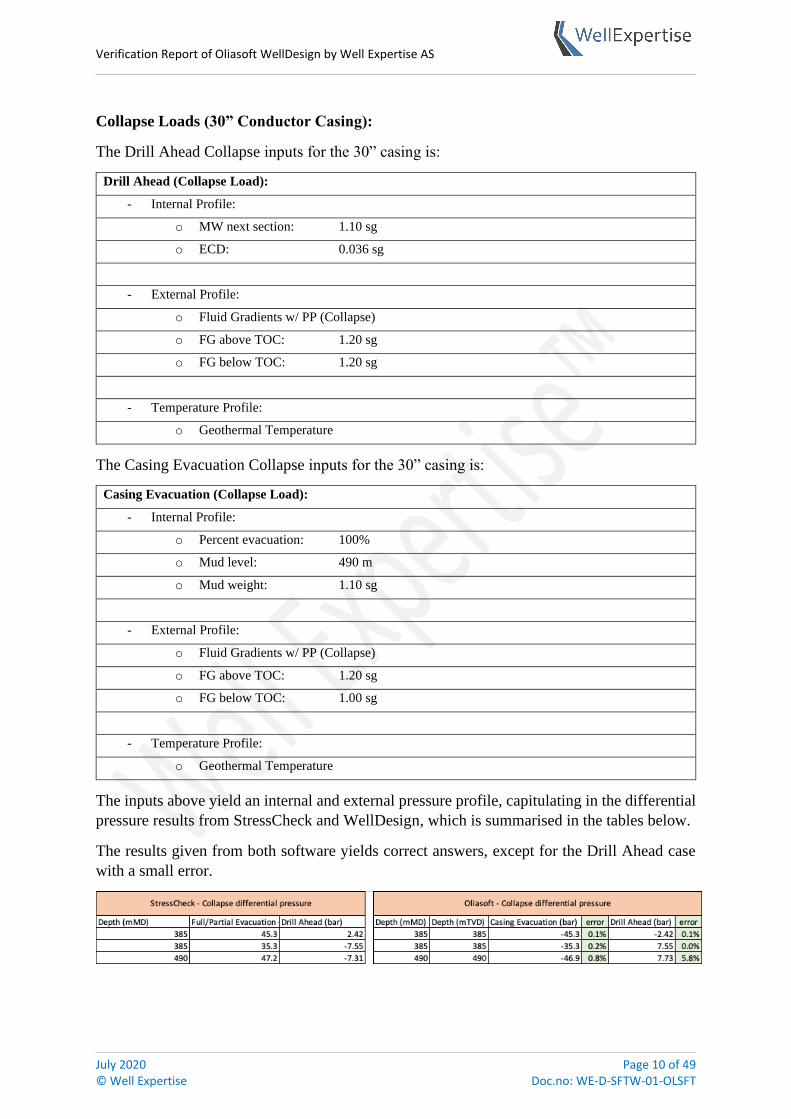
Collapse Loads (30” Conductor Casing):
The Drill Ahead Collapse inputs for the 30” casing is:
Drill Ahead (Collapse Load):
- Internal Profile:
o MW next section: 1.10 sg
o ECD: 0.036 sg
- External Profile:
o Fluid Gradients w/ PP (Collapse)
o FG above TOC: 1.20 sg
o FG below TOC: 1.20 sg
- Temperature Profile:
o Geothermal Temperature
The Casing Evacuation Collapse inputs for the 30” casing is:
Casing Evacuation (Collapse Load):
- Internal Profile:
o Percent evacuation: 100%
o Mud level: 490 m
o Mud weight: 1.10 sg
- External Profile:
o Fluid Gradients w/ PP (Collapse)
o FG above TOC: 1.20 sg
o FG below TOC: 1.00 sg
- Temperature Profile:
o Geothermal Temperature
The inputs above yield an internal and external pressure profile, capitulating in the differential
pressure results from StressCheck and WellDesign, which is summarised in the tables below.
The results given from both software yields correct answers, except for the Drill Ahead case
with a small error.

Verification Report of Oliasoft WellDesign by Well Expertise AS
July 2020 Page 11 of 49 © Well Expertise Doc.no: WE-D-SFTW-01-OLSFT
Installation Loads (30” Conductor Casing):
The Running in Hole Installation inputs for the 30” casing is:
Running in Hole (Installation Load):
- Internal Profile:
o Running speed: 1.00 m/s
- Temperature Profile:
o Bottom hole Circulating Temperature
The Overpull Installation inputs for the 30” casing is:
Overpull (Installation Load):
- Internal Profile:
o Overpull force: 50 MT
o Mud level: 0.00 sg
o Mud weight: 1.10 sg
- Temperature Profile:
o Geothermal Temperature
Inputs from the two above installation tables are used to make an axial profile through the depth
of the casing and is summarised in the table below.
There is seen a larger error in the software outputs regarding the installation loads. This is
reported to both WE and Oliasoft personnel and will further be compiled.

Verification Report of Oliasoft WellDesign by Well Expertise AS
July 2020 Page 12 of 49 © Well Expertise Doc.no: WE-D-SFTW-01-OLSFT
2.3.2. 20” Surface Casing Loads
Burst Load (20” Conductor casing):
The Lost Returns w/ Water Burst inputs for the 20” casing is:
Lost Returns w/ Water (Burst Load):
- Internal Profile:
o Mud/Water interface: 756 m
o Frac. Margin of err.: 0.00
o MW in hole: 1.35 sg
- External Profile:
o Fluid Gradients w/ PP (Burst)
o FG above TOC: 1.10 sg
o FG below TOC: 1.00 sg
- Temperature Profile:
o Geothermal Temperature
The inputs above yield an internal and external pressure profile, capitulating in the differential
pressure results from StressCheck and WellDesign, which is summarised in the tables below.
As seen from the table below, the burst loads in both software coincides well.

Verification Report of Oliasoft WellDesign by Well Expertise AS
July 2020 Page 13 of 49 © Well Expertise Doc.no: WE-D-SFTW-01-OLSFT
Collapse Loads (20” Conductor Casing):
The Cementing Collapse inputs for the 20” casing is:
Cementing (Collapse Load):
- Internal Profile:
o Mud weight: 1.20 sg
- External Profile:
o Mud and Cement Slurry
- Temperature Profile:
o Geothermal Temperature
The Drill Ahead Collapse inputs for the 20” casing is:
Drill Ahead (Collapse Load):
- Internal Profile:
o MW next section: 1.35 sg
o ECD: 0.036 sg
- External Profile:
o Fluid Gradients w/ PP (Collapse)
o FG above TOC: 1.20 sg
o FG below TOC: 1.20 sg
- Temperature Profile:
o Geothermal Temperature
The Casing Evacuation inputs for the 20” casing is:
Casing Evacuation (Collapse Load):
- Internal Profile:
o Percent evacuation: -
o Mud level: 765 m
o Mud weight: 1.20 sg
- External Profile:
o Fluid Gradients w/ PP (Collapse)
o FG above TOC: 1.20 sg
o FG below TOC: 1.20 sg
- Temperature Profile:
o Geothermal Temperature

Verification Report of Oliasoft WellDesign by Well Expertise AS
July 2020 Page 14 of 49 © Well Expertise Doc.no: WE-D-SFTW-01-OLSFT
The inputs above yield an internal and external pressure profile, resulting in the differential
pressure results from StressCheck and WellDesign, which is summarised in the tables below.
As seen from the table below, the collapse loads in both software coincides well.

Verification Report of Oliasoft WellDesign by Well Expertise AS
July 2020 Page 15 of 49 © Well Expertise Doc.no: WE-D-SFTW-01-OLSFT
Installation Loads (20” Conductor Casing):
The Overpull Installation inputs for the 20” casing is:
Overpull (Installation Load):
- Internal Profile:
o Overpull force: 24 MT
- Temperature Profile:
o Geothermal Temperature
The Running in Hole Installation inputs for the 20” casing is:
Running in Hole (Installation Load):
- Internal Profile:
o Running speed: 1.00 m/s
- Temperature Profile:
o Bottomhole Circulating Temperature
Inputs from the two above installation tables are used to make an axial profile through the depth
of the casing and is summarised in the tables below.
There is seen a larger error in the software outputs regarding the installation loads. This is
reported to both WE and Oliasoft personnel and will further be compiled.
Apparent (w/Bending) Actual (w/o Bending) Apparent (w/Bending) Actual (w/o Bending)
385 219 219 88 88
490 201 201 70 70
600 183 183 52 52
685 169 169 37 37
700 166 166 35 35
765 155 155 24 24
Depth (mMD)Running in Hole (tonne) Overpull Force (tonne)
StressCheck - Axial/Installation loads
Apparent (w/Bending) error Actual (w/o Bending) error Apparent (w/Bending) error Actual (w/o Bending) error
385 385 219 0.1% 219 0.1% 89 1.0% 89 1.0%
490 490 202 0.1% 202 0.1% 71 1.2% 71 1.2%
600 600 183 0.1% 183 0.1% 52 0.0% 52 0.0%
685 685 169 0.1% 169 0.1% 37 0.0% 37 0.0%
700 700 166 0.1% 166 0.1% 35 0.0% 35 0.0%
765 765 155 0.1% 155 0.1% 24 0.0% 24 0.0%
Depth (mMD) Depth (mTVD)Overpull Force (tonne)Running in Hole (tonne)
Oliasoft - Axial/Installation loads

Verification Report of Oliasoft WellDesign by Well Expertise AS
July 2020 Page 16 of 49 © Well Expertise Doc.no: WE-D-SFTW-01-OLSFT
2.3.3. 13 3/8” Intermediate Casing Loads
Burst Loads (13 3/8” Intermediate Casing):
The Displacement to Gas Burst inputs for the 13 3/8” casing is:
Displacement to Gas (Burst Load):
- Internal Profile:
o Influx depth: 5500 m
o Mud/gas interface: 0 m
o Mud weight: 1.40 sg
o Gas gradient: 0.230666
o Limit frac @ shoe: No
o Frac. Margin of err.: 0.00 sg
- External Profile:
o Fluid Gradients w/ PP (Burst)
o FG above TOC: 1.35 sg
o FG below TOC: 1.00 sg
- Temperature Profile:
o Geothermal Temperature
The Drill Ahead Burst load inputs for the 13 3/8” casing is:
Drill Ahead (Burst Load):
- Internal Profile:
o MW next section: 1.40 sg
o ECD: 0.036 sg
- External Profile:
o Fluid Gradients w/ PP (Burst)
o FG above TOC: 1.35 sg
o FG below TOC: 1.00 sg
- Temperature Profile:
o Geothermal Temperature
The Frac @ Shoe /GG Above Burst inputs for the 13 3/8” casing is:
Frac @ Shoe /GG Above (Burst Load):
- Internal Profile:
o Gas Gradient Above: 0.230666 sg
o Frac. Margin of err.: 0.00 sg

Verification Report of Oliasoft WellDesign by Well Expertise AS
July 2020 Page 17 of 49 © Well Expertise Doc.no: WE-D-SFTW-01-OLSFT
- External Profile:
o Fluid Gradients w/ PP (Burst)
o FG above TOC: 1.35 sg
o FG below TOC: 1.00 sg
- Temperature Profile:
o Geothermal Temperature
The Gas Over Mud Ratio Burst inputs for the 13 3/8” casing is:
Gas Over Mud Ratio (Burst Load):
- Internal Profile:
o Influx depth: 5500 m
o Gas gradient: 0.2307 sg
o Frac. Margin of err.: 0.00 sg
o Mud @ Shoe Next: 1.40 sg
o Gas percent: 50%
o Depth reference 385 m
o MASP/MAWP to frac @ shoe: No
o Limit to frac @ shoe: No
- External Profile:
o Fluid Gradients w/ PP (Burst)
o FG above TOC: 1.35 sg
o FG below TOC: 1.00 sg
- Temperature Profile:
o Geothermal Temperature
The Lost Returns w/ Water Burst inputs for the 13 3/8” casing is:
Lost Returns w/ Water (Burst Load):
- Internal Profile:
o Mud/Water interface: 3760 m
o Frac. Margin of err.: 0.00
o MW in hole: 1.40 sg
- External Profile:
o Fluid Gradients w/ PP (Burst)
o FG above TOC: 1.35 sg
o FG below TOC: 1.00 sg

Verification Report of Oliasoft WellDesign by Well Expertise AS
July 2020 Page 18 of 49 © Well Expertise Doc.no: WE-D-SFTW-01-OLSFT
- Temperature Profile:
o Geothermal Temperature
The Pressure Test Burst inputs for the 13 3/8” casing is:
Pressure Test (Burst Load):
- Internal Profile:
o Test Pressure: 300 bar
o Fluid density: 1.35 sg
- External Profile:
o Fluid Gradients w/ PP (Burst)
o FG above TOC: 1.35 sg
o FG below TOC: 1.00 sg
- Temperature Profile:
o Geothermal Temperature
The Gas Kick Profile Burst inputs for the 13 3/8” casing is:
Gas Kick Profile (Burst Load):
- Internal Profile:
o Influx depth: 5500 m
o Kick volume: 5 m3
o Kick intensity: 0.06 sg
o Max mud weight: 1.30 sg
o Kick gas density: 0.7
o Fracture MoE: 385 m
o DP OD: 5.5”
o DC OD: 6.5”
o DC length: 150 m
o Limit frac. @ shoe: No
- External Profile:
o Fluid Gradients w/ PP (Burst)
o FG above TOC: 1.35 sg
o FG below TOC: 1.00 sg
- Temperature Profile:
o Geothermal Temperature

Verification Report of Oliasoft WellDesign by Well Expertise AS
July 2020 Page 19 of 49 © Well Expertise Doc.no: WE-D-SFTW-01-OLSFT
The inputs above yield an internal and external pressure profile, capitulating in the differential
pressure results from StressCheck and WellDesign, which is summarised in the tables below.
As seen from the table below, the burst loads in both software coincides well.

Verification Report of Oliasoft WellDesign by Well Expertise AS
July 2020 Page 20 of 49 © Well Expertise Doc.no: WE-D-SFTW-01-OLSFT
Collapse Loads (13 3/8” Intermediate Casing):
The Casing Evacuation Collapse inputs for the 13 3/8” casing is:
Casing Evacuation (Collapse Load):
- Internal Profile:
o Percent evacuation: -
o Mud level: 3760 m
o Mud weight: 1.40 sg
- External Profile:
o Fluid Gradients w/ PP (Collapse)
o FG above TOC: 1.35 sg
o FG below TOC: 1.35 sg
- Temperature Profile:
o Geothermal Temperature
The Cementing Collapse inputs for the 13 3/8” casing is:
Cementing (Collapse Load):
- Internal Profile:
o Mud weight: 1.20 sg
- External Profile:
o Mud and Cement Slurry
- Temperature Profile:
o Geothermal Temperature
The Lost Return w/ Mud Drop Collapse inputs for the 13 3/8” casing is:
Lost Returns w/ Mud Drop (Collapse Load):
- Internal Profile:
o Lost return depth: 5500 m
o Pore pressure override: -
o MW in hole: 1.35 sg
- External Profile:
o Fluid Gradients w/ PP (Collapse)
o FG above TOC: 1.30 sg
o FG below TOC: 1.30 sg
- Temperature Profile:
o Geothermal Temperature

Verification Report of Oliasoft WellDesign by Well Expertise AS
July 2020 Page 21 of 49 © Well Expertise Doc.no: WE-D-SFTW-01-OLSFT
The inputs above yield an internal and external pressure profile, capitulating in the differential
pressure results from StressCheck and WellDesign, which is summarised in the tables below.
The results given from both software yields correct answers, except for the Lost Returns with
Mud Drop case with a small error. This can be explained with the dissimilar depth values
corresponding to the pressure values. Especially, for Lost Returns-case the values are sensitive
due to the low differential pressure and large changes in them for depth-to-depth. For the depth-
values that is similar, it is seen the exact same differential pressure, ref. depths from 385 meters
to 2,500 meters.
Depth (mMD) Depth (mTVD) Casing Evacuation (bar) error Cementing (bar) error Lost Returns With Mud Drop (bar) error
385 385 -51 0.0% 6 0.0% -18 20.0%
765 765 -101 0.1% 11 0.0% -16 21.9%
800 800 -106 0.1% 12 0.0% -16 22.1%
901 900 -119 0.1% 13 0.1% -15 22.6%
1004 1000 -132 1.4% 15 1.4% -15 22.9%
1128 1110 -147 0.1% 16 0.0% -14 23.9%
2500 2264 -300 0.1% 33 0.0% -11 17.1%
3152 2812 -393 0.1% 5 29.1% -40 5.9%
3254 2900 -392 0.1% 1 41.1% -28 8.5%
3366 3000 -397 0.2% -4 6.7% -20 6.9%
3479 3100 -398 0.1% -9 10.4% -7 28.8%
3500 3119 -401 0.2% -10 4.3% -8 13.8%
3597 3200 -414 1.0% -15 8.7% -10 3.9%
3728 3300 -427 0.3% -20 1.5% -10 9.4%
3760 3323 -427 0.1% -21 0.0% -7 12.1%
Oliasoft - Collapse differential pressure
Depth (MD) (m) Full/Partial Evacuation (bar) Cementing (bar) Lost Returns (bar)
385 51 -6 22
765 101 -11 20
800 106 -12 20
900 119 -13 20
1020 134 -15 19
1128 147 -16 19
2500 299 -33 13
3180 392 -4 38
3240 392 -1 31
3360 397 4 21
3460 398 8 10
3510 402 11 9
3570 410 14 11
3720 426 20 11
3760 427 21 8
StressCheck - Collapse differential pressure

Verification Report of Oliasoft WellDesign by Well Expertise AS
July 2020 Page 22 of 49 © Well Expertise Doc.no: WE-D-SFTW-01-OLSFT
Installation Loads (13 3/8” Intermediate Casing):
The Overpull Installation inputs for the 13 3/8” casing is:
Overpull (Installation Load):
- Internal Profile:
o Overpull force: 109 MT
- Temperature Profile:
o Geothermal Temperature
The Running in Hole Installation inputs for the 13 3/8” casing is:
Running in Hole (Installation Load):
- Internal Profile:
o Running speed: 1.00 m/s
- Temperature Profile:
o Bottomhole Circulating Temperature
Inputs from the two above installation tables are used to make an axial profile through the depth
of the casing and is summarised in the tables below.
There is seen a minor error in the software outputs regarding the installation loads.
Apparent (w/Bending) error Actual (w/o Bending) error Apparent (w/Bending) error Actual (w/o Bending) error
385 385 357 1.7% 357 1.7% 383 1.6% 383 1.6%
765 765 329 2.1% 329 2.1% 355 2.0% 355 2.0%
800 800 384 1.8% 326 2.0% 410 1.7% 352 1.9%
901 900 377 1.7% 317 1.6% 403 1.6% 343 1.5%
1004 1000 370 2.0% 309 2.0% 395 1.9% 335 1.9%
1128 1110 359 1.4% 299 1.3% 385 1.3% 324 1.2%
2186 2000 278 0.3% 217 1.9% 303 0.3% 242 1.6%
2500 2264 254 1.4% 193 0.2% 279 1.3% 218 0.2%
3152 2812 203 1.8% 139 3.2% 228 1.7% 165 2.7%
3254 2900 194 0.3% 129 0.6% 220 0.2% 155 0.4%
3366 3000 186 0.1% 119 0.2% 211 0.0% 145 0.2%
3479 3100 179 0.1% 109 1.9% 204 0.1% 135 1.5%
3500 3119 177 1.6% 107 1.2% 203 1.4% 133 1.1%
3597 3200 169 0.3% 98 2.1% 194 0.2% 124 1.6%
3728 3300 157 0.6% 86 0.8% 183 0.5% 112 0.5%
3760 3323 154 1.0% 83 0.1% 179 0.6% 109 0.0%
Depth (mMD) Depth (mTVD)Running in Hole (tonne) Overpull Force (tonne)
Oliasoft - Axial/Installation load
Apparent (w/Bending) Actual (w/o Bending) Apparent (w/Bending) Actual (w/o Bending)
385 351 351 377 377
765 322 322 348 348
800 377 320 403 345
900 371 312 396 338
1020 362 303 388 329
1128 354 295 379 321
2118 279 221 304 246
2500 250 192 276 218
3180 199 135 225 161
3240 195 130 220 155
3360 186 119 211 145
3450 179 111 205 137
3510 174 106 200 131
3570 169 100 195 126
3720 156 87 182 113
3760 153 83 178 109
Depth (MD) (m)Running in Hole (tonne) Overpull Force (tonne)
StressCheck - Axial/Installation load

Verification Report of Oliasoft WellDesign by Well Expertise AS
July 2020 Page 23 of 49 © Well Expertise Doc.no: WE-D-SFTW-01-OLSFT
2.3.4. 9 5/8” Production Casing Loads
Burst Loads (9 5/8” Production Casing):
The Displacement to Gas Burst inputs for the 9 5/8” casing is:
Displacement to Gas (Burst Load):
- Internal Profile:
o Influx depth: 5500 m
o Mud/gas interface: 0 m
o Mud weight: 1.30 sg
o Gas gradient: 0.2307
o Limit frac @ shoe: No
o Frac. Margin of err.: 0.00 sg
- External Profile:
o Fluid Gradients w/ PP (Burst)
o FG above TOC: 1.40 sg
o FG below TOC: 1.00 sg
- Temperature Profile:
o Geothermal Temperature
The Pressure Test Burst inputs for the 9 5/8” casing is:
Pressure Test (Burst Load):
- Internal Profile:
o Test Pressure: 300 bar
o Fluid density: 1.40 sg
- External Profile:
o Fluid Gradients w/ PP (Burst)
o FG above TOC: 1.40 sg
o FG below TOC: 1.00 sg
- Temperature Profile:
o Geothermal Temperature
The Tubing Leak Burst inputs for the 9 5/8” casing is:
Tubing Leak (Burst Load):
- Internal Profile:
o Perforation Depth: 7500 m
o Packer Depth: 5500 m

Verification Report of Oliasoft WellDesign by Well Expertise AS
July 2020 Page 24 of 49 © Well Expertise Doc.no: WE-D-SFTW-01-OLSFT
o Packer fluid: 1.031 sg
o Gas gravity: 0.7
- External Profile:
o Fluid Gradients w/ PP (Burst)
o FG above TOC: 1.40 sg
o FG below TOC: 1.00 sg
- Temperature Profile:
o Production temp.: 121.25°C
The inputs above yield an internal and external pressure profile, capitulating in the differential
pressure results from StressCheck and WellDesign, which is summarised in the tables below.
As seen from the table below, the burst loads in both software coincides well. The only
deviation seen is when the corresponding depths and differential pressures does not match
perfectly, resulting in a higher/lower pressure.

Verification Report of Oliasoft WellDesign by Well Expertise AS
July 2020 Page 25 of 49 © Well Expertise Doc.no: WE-D-SFTW-01-OLSFT
Collapse Loads (9 5/8” Production Casing):
The Above/Below Packer Collapse inputs for the 9 5/8” casing is:
Above/Below Packer (Collapse Load):
- Internal Profile:
o Perforation Depth: 7500 m
o Packer Depth: 5500 m
o Density above packer: 1.031 sg
o Density below packer: 0.00 sg
o Fluid drop above packer: No
- External Profile:
o Fluid Gradients w/ PP (Collapse)
o FG above TOC: 1.40 sg
o FG below TOC: 1.40 sg
- Temperature Profile:
o Production Temperature: 121.25°C
The Casing Evacuation Collapse inputs for the 9 5/8” casing is:
Casing Evacuation (Collapse Load):
- Internal Profile:
o Percent evacution: -
o Mud level: 5500 m
o Mud weight: 1.20 sg
- External Profile:
o Fluid Gradients w/ PP (Collapse)
o FG above TOC: 1.40 sg
o FG below TOC: 1.40 sg
- Temperature Profile:
o Geothermal Temperature
The Lost Returns w/ Mud Drop Collapse inputs for the 9 5/8” casing is:
Lost Returns w/ Mud Drop (Collapse Load):
- Internal Profile:
o Lost return depth: 5500 m
o Pore pressure override: 1.29 sg
o MW in hole: 1.20 sg
- External Profile:
o Fluid Gradients w/ PP (Collapse)
o FG above TOC: 1.35 sg

Verification Report of Oliasoft WellDesign by Well Expertise AS
July 2020 Page 26 of 49 © Well Expertise Doc.no: WE-D-SFTW-01-OLSFT
o FG below TOC: 1.35 sg
- Temperature Profile:
o Geothermal Temperature
The Gas Migration Collapse inputs for the 9 5/8” casing is:
Gas Migration (Collapse Load):
- Internal Profile:
o Packer fluid: 1.031 sg
- External Profile:
o Gas Migration External Gradient
o Fluid density: 1.40 sg
o Limit to frac @ shoe: Yes
- Temperature Profile:
o Production Temperature: 121.25°C
The inputs above yield an internal and external pressure profile, capitulating in the differential
pressure results from StressCheck and WellDesign, which is summarised in the tables below.
As seen from the table below, the burst loads in both software coincides well.

Verification Report of Oliasoft WellDesign by Well Expertise AS
July 2020 Page 27 of 49 © Well Expertise Doc.no: WE-D-SFTW-01-OLSFT
Installation Loads (9 5/8” Production Casing):
The Overpull Installation inputs for the 9 5/8” casing is:
Overpull (Installation Load):
- Internal Profile:
o Overpull force: 158 MT
- Temperature Profile:
o Geothermal Temperature
The Running in Hole Installation inputs for the 9 5/8” casing is:
Running in Hole (Installation Load):
- Internal Profile:
o Running speed: 1.00 m/s
- Temperature Profile:
o Bottom hole Circulating Temperature
Inputs from the two above installation tables are used to make an axial profile through the depth
of the casing and is summarised in the tables below.
There is seen a minor error in the software outputs regarding the installation loads.
Apparent (w/Bending) Actual (w/o Bending) Apparent (w/Bending) Actual (w/o Bending)
385 292 292 388 388
800 292 292 388 388
900 292 292 388 388
1020 292 292 388 388
1128 292 292 388 388
3180 227 201 322 297
3240 223 198 319 293
3360 217 191 312 287
3450 212 186 307 282
3500 209 183 304 279
3570 205 180 301 275
3720 197 171 292 267
3760 195 169 290 265
3900 187 161 282 257
4260 167 141 263 237
5500 96 62 192 158
Overpull Force (tonne)
StressCheck - Axial/Installation load
Running in Hole (tonne)Depth (MD) (m)
Apparent (w/Bending) error Actual (w/o Bending) error Apparent (w/Bending) error Actual (w/o Bending) error
385 385 292 0.1% 292 0.1% 388 0.0% 388 0.0%
800 800 292 0.1% 292 0.1% 388 0.0% 388 0.0%
901 900 292 0.1% 292 0.1% 388 0.0% 388 0.0%
1004 1000 292 0.1% 292 0.1% 388 0.0% 388 0.0%
1128 1110 292 0.1% 292 0.1% 388 0.0% 388 0.0%
3152 2812 228 0.7% 202 0.3% 324 0.6% 298 0.5%
3254 2900 222 0.5% 195 1.2% 318 0.3% 291 0.7%
3366 3000 216 0.3% 189 1.0% 312 0.1% 285 0.6%
3479 3100 210 0.9% 183 1.8% 306 0.5% 279 1.1%
3500 3119 208 0.2% 182 0.9% 304 0.0% 278 0.5%
3597 3200 203 0.9% 176 1.8% 299 0.5% 272 1.0%
3728 3300 196 0.4% 169 1.2% 292 0.2% 265 0.7%
3760 3323 194 0.2% 167 1.0% 290 0.0% 263 0.5%
3888 3400 187 0.1% 160 0.6% 283 0.2% 256 0.3%
4252 3500 167 0.1% 140 1.0% 262 0.1% 236 0.5%
5500 3500 96 0.3% 62 0.5% 192 0.0% 158 0.0%
Overpull Force (tonne)
Oliasoft - Axial/Installation load
Depth (mMD) Depth (mTVD)Running in Hole (tonne)

Verification Report of Oliasoft WellDesign by Well Expertise AS
July 2020 Page 28 of 49 © Well Expertise Doc.no: WE-D-SFTW-01-OLSFT
2.3.5. 7” Production Liner Loads
Burst Loads (7” Production Liner):
The Tubing Leak Burst inputs for the 7” liner is:
Tubing Leak (Burst Load):
- Internal Profile:
o Perforation Depth: 7500 m
o Packer Depth: 5500 m
o Packer fluid: 1.031 sg
o Gas gravity: 0.7
- External Profile:
o Fluid Gradients w/ PP (Burst)
o FG above TOC: 1.20 sg
o FG below TOC: 1.00 sg
- Temperature Profile:
o Production temp.: 121.25°C
The Green Cement Pressure Test Burst inputs for the 7” liner is:
Green Cement Pressure Test (Burst Load):
- Internal Profile:
o Test Pressure: 300 bar
o Fluid density: 1.40 sg
- External Profile:
o Mud and Cement Slurry
- Temperature Profile:
o Geothermal Temperature
The Cementing Collapse inputs for the 7” liner is:
Cementing (Collapse Load):
- Internal Profile:
o Mud weight: 1.20 sg
- External Profile:
o Mud and Cement Slurry
- Temperature Profile:
o Geothermal Temperature

Verification Report of Oliasoft WellDesign by Well Expertise AS
July 2020 Page 29 of 49 © Well Expertise Doc.no: WE-D-SFTW-01-OLSFT
The inputs above yield an internal and external pressure profile, capitulating in the differential
pressure results from StressCheck and WellDesign, which is summarised in the tables below.
As seen from the table below, the Green Cement Pressure Test burst load coincides well. For
the Tubing Leak load, it is seen a large error. The root of the problem will be discussed with
Oliasoft.

Verification Report of Oliasoft WellDesign by Well Expertise AS
July 2020 Page 30 of 49 © Well Expertise Doc.no: WE-D-SFTW-01-OLSFT
Collapse Loads (7” Production Liner):
The Casing Evacuation Collapse inputs for the 7” liner is:
Casing Evacuation (Collapse Load):
- Internal Profile:
o Percent evacuation: 100%
o Mud level: -
o Mud weight: 1.20 sg
- External Profile:
o Fluid Gradients w/ PP (Collapse)
o FG above TOC: 1.20 sg
o FG below TOC: 1.20 sg
- Temperature Profile:
o Geothermal Temperature
The Above/Below Packer Collapse inputs for the 7” liner is:
Above/Below Packer (Collapse Load):
- Internal Profile:
o Perforation Depth: 7500 m
o Packer Depth: 5500 m
o Density above packer: 1.031 sg
o Density below packer: 0.00 sg
o Fluid drop above packer: Yes
- External Profile:
o Fluid Gradients w/ PP (Collapse)
o FG above TOC: 1.20 sg
o FG below TOC: 1.20 sg
- Temperature Profile:
o Production Temperature: 121.25°C
The inputs above yield an internal and external pressure profile, capitulating in the differential
pressure results from StressCheck and WellDesign, which is summarised in the tables below.
As seen from the table below, all the collapse loads in both software coincides well.

Verification Report of Oliasoft WellDesign by Well Expertise AS
July 2020 Page 31 of 49 © Well Expertise Doc.no: WE-D-SFTW-01-OLSFT
Installation Loads (7” Production Liner):
The Overpull Installation inputs for the 7” liner is:
Overpull (Installation Load):
- Internal Profile:
o Overpull force: 215 MT
- Temperature Profile:
o Geothermal Temperature
The Running in Hole Installation inputs for the 7” liner is:
Running in Hole (Installation Load):
- Internal Profile:
o Running speed: 1.00 m/s
- Temperature Profile:
o Bottom hole Circulating Temperature
Inputs from the two above installation tables are used to make an axial profile through the depth
of the casing and is summarised in the tables below.
There is seen a minor error in the software outputs regarding the installation loads.

Verification Report of Oliasoft WellDesign by Well Expertise AS
July 2020 Page 32 of 49 © Well Expertise Doc.no: WE-D-SFTW-01-OLSFT
2.3.6. 5” Production Tubing Loads
Burst Load (5” Production Tubing):
The Pressure Test Burst inputs for the 5” tubing is:
Pressure Test (Burst Load):
- Internal Profile:
o Test Pressure: 345 bar
o Fluid density: 1.031 sg
- External Profile:
o Fluid Gradients w/ PP (Burst)
o FG above TOC: -
o FG below TOC: 1.00 sg
- Temperature Profile:
o Geothermal Temperature
…

Verification Report of Oliasoft WellDesign by Well Expertise AS
July 2020 Page 33 of 49 © Well Expertise Doc.no: WE-D-SFTW-01-OLSFT
Collapse Load (5” Production Tubing):
The Casing Evacuation Collapse inputs for the 5” tubing is:
Casing Evacuation (Collapse Load):
- Internal Profile:
o Percent evacution: 100%
o Mud level: -
o Mud weight: 1.031 sg
- External Profile:
o Fluid Gradients w/ PP (Collapse)
o FG above TOC: 1.031 sg
o FG below TOC: 1.031 sg
- Temperature Profile:
o Geothermal Temperature
The inputs above yield an internal and external pressure profile, capitulating in the differential
pressure results from StressCheck and WellDesign, which is summarised in the tables below.
As seen from the table below, the Collapse load coincides well with both software. The small
amount of error from the table is due to comparing depths with minor increments between the
points.

Verification Report of Oliasoft WellDesign by Well Expertise AS
July 2020 Page 34 of 49 © Well Expertise Doc.no: WE-D-SFTW-01-OLSFT
Installation Loads (5” Production Tubing):
The Overpull Installation inputs for the 5” tubing is:
Overpull (Installation Load):
- Internal Profile:
o Overpull force: 100 MT
- Temperature Profile:
o Geothermal Temperature
The Running in Hole Installation inputs for the 5” tubing is:
Running in Hole (Installation Load):
- Internal Profile:
o Running speed: 1.00 m/s
- Temperature Profile:
o Bottom hole Circulating Temperature
Inputs from the two above installation tables are used to make an axial profile through the depth
of the casing and is summarised in the tables below.
There is seen a minor error in the software outputs regarding the installation loads.

Verification Report of Oliasoft WellDesign by Well Expertise AS
July 2020 Page 35 of 49 © Well Expertise Doc.no: WE-D-SFTW-01-OLSFT
2.4. Temperature Analysis
Six well operational procedures have been chosen as comparison; one drilling and five
production scenarios. The first drilling scenario is drilling into the reservoir, i.e. the last hole
to be drilling. While the other loads are more towards production, whereas first is to displace
the well to the completion fluid followed by a test-scenario with three days of production and
shut-in the well for a short period of 24 hours, then a steady-state production scenario for 10
years and finally a late stage production where the reservoir is depleted, meaning low flow
rates. Each scenario will be described in more detail and the data output will be presented to
compare below.
2.4.1. Drilling of the reservoir section
Drilling the last section, a 2000 m 8 ½” open hole, from a depth of 5500/3500 m MD/TVD to
7500/3500 m MD/TVD. This section only consists of horizontal drilling, meaning a 90° inclination.
Initial conditions: Geothermal temperature
Section: 8 ½” OH
Drillpipe/BHA: 5 ½”
Depth: 7500 m
Drilling mud: Default WBM (1.20 sg)
Circulation rate: 4000 L/min
Pump pressure: 25 bar
Volume: 20 m3
Ambient temperature: 3.43°C
ROP: 40 m/h
Drill power: 4590 kW
These settings will yield the following temperature behaviour in WellCat and Oliasoft.

Verification Report of Oliasoft WellDesign by Well Expertise AS
July 2020 Page 36 of 49 © Well Expertise Doc.no: WE-D-SFTW-01-OLSFT
2.4.2. Displacing the well to completion fluid
After completion of the drilling, the well will be displaced to the completion fluid. A 1.20 sg
WBM mud is used as the completion fluid in this case. The following values was used.
Operation type: Circulate
Initial conditions: Geothermal temperature
Section: 8 ½” OH
Sequence: Before/while casing installation
Drillpipe/BHA: 5 ½”
Depth: 7500 m
Circulation fluid: Default WBM (1.20 sg)
Circulation rate: 2500 L/min
Volume: 250 m3
Ambient temperature: 3.43°C
Simulation time: 24 hours
These settings will yield the following results in a table.

Verification Report of Oliasoft WellDesign by Well Expertise AS
July 2020 Page 37 of 49 © Well Expertise Doc.no: WE-D-SFTW-01-OLSFT
2.4.3. Producing for three days
This production behaviour is a short temperature build up for three days. The production rate
is set to 15,000 barrels per day.
Operation type: Production
Initial conditions: Geothermal temperature
Production flow path: Inside tubing
Wellhead pressure: 50 bar
Inflow depth: 7500 m
Inlet temperature: 121°C
Production fluid: Oil 24 API

Verification Report of Oliasoft WellDesign by Well Expertise AS
July 2020 Page 38 of 49 © Well Expertise Doc.no: WE-D-SFTW-01-OLSFT
PVT model: Peng Robinson
Multiphase model: Zhang
Production rate: 15,000 bpd
Water cut: 0%
Flow behaviour: Transient

Verification Report of Oliasoft WellDesign by Well Expertise AS
July 2020 Page 39 of 49 © Well Expertise Doc.no: WE-D-SFTW-01-OLSFT
2.4.4. Shut-in well short for 24 hours
In this temperature model, the well is shut-in for a short time right after having produced for
three days. Following inputs are used.
Operation type: Shut-in
Initial conditions: Production for 3 days
Simulation time: 24 hours

Verification Report of Oliasoft WellDesign by Well Expertise AS
July 2020 Page 40 of 49 © Well Expertise Doc.no: WE-D-SFTW-01-OLSFT
2.4.5. Steady-state production for 10 years
After a transient flow, it is assumed a steady-state behaviour for 10 years and the fluid
temperature analysis is done based on the following inputs.
Operation type: Production
Initial conditions: Shut-in well short for 24 hours
Production flow path: Inside tubing
Riser: Installed
Wellhead pressure: 20 bar
Inflow depth: 7500 m
Inlet temperature: 121°C
Production fluid: Oil 31 API
PVT model: Peng Robinson
Multiphase model: Beggs & Brill
Production rate: 15,000 bpd
Water cut: 0%
Flow behaviour: Steady-State
Simulation time: 10 years
Verification Report of Oliasoft WellDesign by Well Expertise AS
July 2020 Page 41 of 49 © Well Expertise Doc.no: WE-D-SFTW-01-OLSFT
2.4.6. Late stage production for one year
This production case simulates temperature behaviour for the last couple of years with a lower
production rate and depleted reservoir. The following inputs are used.
Operation type: Production
Initial conditions: Production for 10 years
Production flow path: Inside tubing
Wellhead pressure: 850.89 bar
PVT model: Peng Robinson
Multiphase model: Beggs & Brill
Production rate: 3,000 bpd
Water cut: 0%
Flow behaviour: Pseudo Steady-State
Simulation time: 365 days

Verification Report of Oliasoft WellDesign by Well Expertise AS
July 2020 Page 42 of 49 © Well Expertise Doc.no: WE-D-SFTW-01-OLSFT

Verification Report of Oliasoft WellDesign by Well Expertise AS
July 2020 Page 43 of 49 © Well Expertise Doc.no: WE-D-SFTW-01-OLSFT
Pore Pressure- & Fracture Gradient values
Depth (mTVD)
Pore Pressure (sg)
PP Pressure (bar)
Fracture Gradient (sg)
FG Pressure (bar)
385 0.94 35 1.64 62
600 1.02 60 1.65 97
685 0.98 66 1.62 109
700 1.04 71 1.68 115
800 1.03 81 1.68 132
900 1.06 93 1.72 152
1000 1.06 104 1.73 170
1100 1.08 116 1.66 179
1200 1.21 142 1.80 212
1300 1.22 156 1.82 232
1400 1.23 169 1.84 253
1500 1.22 179 1.84 271
1600 1.18 185 1.81 284
1700 1.18 197 1.82 303
1800 1.19 210 1.71 302
1900 1.21 225 1.72 320
2000 1.31 257 1.84 361
2100 1.30 268 1.84 379
2200 1.31 283 1.86 401
2300 1.31 295 1.87 422
2400 1.35 318 1.92 452
2500 1.34 329 1.92 471
2600 1.41 360 1.87 477
2700 1.42 376 1.89 500
2800 1.43 393 1.91 524
2900 1.38 392 1.87 532
3000 1.35 397 1.85 544
3100 1.31 398 1.82 553
3200 1.32 414 1.84 577
3300 1.32 427 1.85 599
3400 1.28 427 1.82 607
3500 1.29 443 1.84 632
3600 1.37 484 1.83 646
3700 1.40 508 1.87 679
3800 1.42 529 1.89 704
3900 1.41 539 1.91 731
4000 1.40 549 1.98 777

Verification Report of Oliasoft WellDesign by Well Expertise AS
July 2020 Page 44 of 49 © Well Expertise Doc.no: WE-D-SFTW-01-OLSFT
Trajectory output
Compass Trajectory
Oliasoft Trajectory
Data-Entry Mode MD (m) INC (°) AZ (°)
TVD (m) MD (m) Inc (°) Azi (°) TVD (m)
MD-INC-AZ 0 0 0 0 0 0 0 0
MD-INC-AZ 30 0 0 30 30 0 0 30
MD-INC-AZ 60 0 0 60 60 0 0 60
MD-INC-AZ 90 0 0 90 90 0 0 90
MD-INC-AZ 120 0 0 120 120 0 0 120
MD-INC-AZ 150 0 0 150 150 0 0 150
MD-INC-AZ 180 0 0 180 180 0 0 180
MD-INC-AZ 210 0 0 210 210 0 0 210
MD-INC-AZ 240 0 0 240 240 0 0 240
MD-INC-AZ 270 0 0 270 270 0 0 270
MD-INC-AZ 300 0 0 300 300 0 0 300
MD-INC-AZ 330 0 0 330 330 0 0 330
MD-INC-AZ 360 0 0 360 360 0 0 360
MD-INC-AZ 390 0 0 390 390 0 0 390
MD-INC-AZ 420 0 0 420 420 0 0 420
MD-INC-AZ 450 0 0 450 450 0 0 450
MD-INC-AZ 480 0 0 480 480 0 0 480
MD-INC-AZ 510 0 0 510 510 0 0 510
MD-INC-AZ 540 0 0 540 540 0 0 540
MD-INC-AZ 570 0 0 570 570 0 0 570
MD-INC-AZ 600 0 0 600 600 0 0 600
MD-INC-AZ 630 0 0 630 630 0 0 630
MD-INC-AZ 660 0 0 660 660 0 0 660
MD-INC-AZ 690 0 0 690 690 0 0 690
MD-INC-AZ 720 0 0 720 720 0 0 720
MD-INC-AZ 750 0 0 750 750 0 0 750
MD-INC-AZ 780 0 0 780 780 0 0 780
MD-INC-AZ 800 0 0 800 800 0 0 800
MD-INC-AZ 810 1 350.88 810 810 1 -9.1174 810
MD-INC-AZ 840 4 350.88 840 840 4 -9.1174 840
MD-INC-AZ 870 7 350.88 870 870 7 -9.1174 870
MD-INC-AZ 900 10 350.88 899 900 10 -9.1174 899
MD-INC-AZ 930 13 350.88 929 930 13 -9.1174 929
MD-INC-AZ 960 16 350.88 958 960 16 -9.1174 958
MD-INC-AZ 990 19 350.88 987 990 19 -9.1174 987
MD-INC-AZ 1020 22 350.88 1015 1020 22 -9.1174 1015
MD-INC-AZ 1050 25 350.88 1042 1050 25 -9.1174 1042
MD-INC-AZ 1080 28 350.88 1069 1080 28 -9.1174 1069
MD-INC-AZ 1110 31 350.88 1095 1110 31 -9.1174 1095
MD-INC-AZ 1127.68 32.77 350.88 1110 1127.68 32.768 -9.1174 1110

Verification Report of Oliasoft WellDesign by Well Expertise AS
July 2020 Page 45 of 49 © Well Expertise Doc.no: WE-D-SFTW-01-OLSFT
MD-INC-AZ 1140 32.77 350.88 1120 1140 32.768 -9.1174 1120
MD-INC-AZ 1170 32.77 350.88 1146 1170 32.768 -9.1174 1146
MD-INC-AZ 1200 32.77 350.88 1171 1200 32.768 -9.1174 1171
MD-INC-AZ 1230 32.77 350.88 1196 1230 32.768 -9.1174 1196
MD-INC-AZ 1260 32.77 350.88 1221 1260 32.768 -9.1174 1221
MD-INC-AZ 1290 32.77 350.88 1247 1290 32.768 -9.1174 1247
MD-INC-AZ 1320 32.77 350.88 1272 1320 32.768 -9.1174 1272
MD-INC-AZ 1350 32.77 350.88 1297 1350 32.768 -9.1174 1297
MD-INC-AZ 1380 32.77 350.88 1322 1380 32.768 -9.1174 1322
MD-INC-AZ 1410 32.77 350.88 1348 1410 32.768 -9.1174 1348
MD-INC-AZ 1440 32.77 350.88 1373 1440 32.768 -9.1174 1373
MD-INC-AZ 1470 32.77 350.88 1398 1470 32.768 -9.1174 1398
MD-INC-AZ 1500 32.77 350.88 1423 1500 32.768 -9.1174 1423
MD-INC-AZ 1530 32.77 350.88 1448 1530 32.768 -9.1174 1448
MD-INC-AZ 1560 32.77 350.88 1474 1560 32.768 -9.1174 1474
MD-INC-AZ 1590 32.77 350.88 1499 1590 32.768 -9.1174 1499
MD-INC-AZ 1620 32.77 350.88 1524 1620 32.768 -9.1174 1524
MD-INC-AZ 1650 32.77 350.88 1549 1650 32.768 -9.1174 1549
MD-INC-AZ 1680 32.77 350.88 1575 1680 32.768 -9.1174 1575
MD-INC-AZ 1710 32.77 350.88 1600 1710 32.768 -9.1174 1600
MD-INC-AZ 1740 32.77 350.88 1625 1740 32.768 -9.1174 1625
MD-INC-AZ 1770 32.77 350.88 1650 1770 32.768 -9.1174 1650
MD-INC-AZ 1800 32.77 350.88 1675 1800 32.768 -9.1174 1675
MD-INC-AZ 1830 32.77 350.88 1701 1830 32.768 -9.1174 1701
MD-INC-AZ 1860 32.77 350.88 1726 1860 32.768 -9.1174 1726
MD-INC-AZ 1890 32.77 350.88 1751 1890 32.768 -9.1174 1751
MD-INC-AZ 1920 32.77 350.88 1776 1920 32.768 -9.1174 1776
MD-INC-AZ 1950 32.77 350.88 1802 1950 32.768 -9.1174 1802
MD-INC-AZ 1980 32.77 350.88 1827 1980 32.768 -9.1174 1827
MD-INC-AZ 2010 32.77 350.88 1852 2010 32.768 -9.1174 1852
MD-INC-AZ 2040 32.77 350.88 1877 2040 32.768 -9.1174 1877
MD-INC-AZ 2070 32.77 350.88 1902 2070 32.768 -9.1174 1902
MD-INC-AZ 2100 32.77 350.88 1928 2100 32.768 -9.1174 1928
MD-INC-AZ 2130 32.77 350.88 1953 2130 32.768 -9.1174 1953
MD-INC-AZ 2160 32.77 350.88 1978 2160 32.768 -9.1174 1978
MD-INC-AZ 2190 32.77 350.88 2003 2190 32.768 -9.1174 2003
MD-INC-AZ 2220 32.77 350.88 2029 2220 32.768 -9.1174 2029
MD-INC-AZ 2250 32.77 350.88 2054 2250 32.768 -9.1174 2054
MD-INC-AZ 2280 32.77 350.88 2079 2280 32.768 -9.1174 2079
MD-INC-AZ 2310 32.77 350.88 2104 2310 32.768 -9.1174 2104
MD-INC-AZ 2340 32.77 350.88 2130 2340 32.768 -9.1174 2130
MD-INC-AZ 2370 32.77 350.88 2155 2370 32.768 -9.1174 2155
MD-INC-AZ 2400 32.77 350.88 2180 2400 32.768 -9.1174 2180
MD-INC-AZ 2430 32.77 350.88 2205 2430 32.768 -9.1174 2205
MD-INC-AZ 2460 32.77 350.88 2230 2460 32.768 -9.1174 2230
MD-INC-AZ 2490 32.77 350.88 2256 2490 32.768 -9.1174 2256
MD-INC-AZ 2520 32.77 350.88 2281 2520 32.768 -9.1174 2281

Verification Report of Oliasoft WellDesign by Well Expertise AS
July 2020 Page 46 of 49 © Well Expertise Doc.no: WE-D-SFTW-01-OLSFT
MD-INC-AZ 2550 32.77 350.88 2306 2550 32.768 -9.1174 2306
MD-INC-AZ 2580 32.77 350.88 2331 2580 32.768 -9.1174 2331
MD-INC-AZ 2610 32.77 350.88 2357 2610 32.768 -9.1174 2357
MD-INC-AZ 2640 32.77 350.88 2382 2640 32.768 -9.1174 2382
MD-INC-AZ 2670 32.77 350.88 2407 2670 32.768 -9.1174 2407
MD-INC-AZ 2700 32.77 350.88 2432 2700 32.768 -9.1174 2432
MD-INC-AZ 2730 32.77 350.88 2457 2730 32.768 -9.1174 2457
MD-INC-AZ 2760 32.77 350.88 2483 2760 32.768 -9.1174 2483
MD-INC-AZ 2790 32.77 350.88 2508 2790 32.768 -9.1174 2508
MD-INC-AZ 2820 32.77 350.88 2533 2820 32.768 -9.1174 2533
MD-INC-AZ 2850 32.77 350.88 2558 2850 32.768 -9.1174 2558
MD-INC-AZ 2880 32.77 350.88 2584 2880 32.768 -9.1174 2584
MD-INC-AZ 2910 32.77 350.88 2609 2910 32.768 -9.1174 2609
MD-INC-AZ 2940 32.77 350.88 2634 2940 32.768 -9.1174 2634
MD-INC-AZ 2970 32.77 350.88 2659 2970 32.768 -9.1174 2659
MD-INC-AZ 3000 32.77 350.88 2684 3000 32.768 -9.1174 2684
MD-INC-AZ 3030 32.77 350.88 2710 3030 32.768 -9.1174 2710
MD-INC-AZ 3060 32.77 350.88 2735 3060 32.768 -9.1174 2735
MD-INC-AZ 3090 32.77 350.88 2760 3090 32.768 -9.1174 2760
MD-INC-AZ 3120 32.77 350.88 2785 3120 32.768 -9.1174 2785
MD-INC-AZ 3152.09 32.77 350.88 2812 3152.088 32.768 -9.1174 2812
MD-INC-AZ 3180 31.27 355.32 2836 3180 31.2681 -4.6757 2836
MD-INC-AZ 3210 29.84 0.52 2862 3210 29.8417 0.5185 2862
MD-INC-AZ 3240 28.64 6.15 2888 3240 28.6361 6.1454 2888
MD-INC-AZ 3270 27.68 12.17 2915 3270 27.6804 12.1743 2915
MD-INC-AZ 3300 27 18.54 2941 3300 27.0011 18.5397 2941
MD-INC-AZ 3330 26.62 25.14 2968 3330 26.6197 25.1401 2968
MD-INC-AZ 3360 26.55 31.84 2995 3360 26.549 31.8449 2995
MD-INC-AZ 3390 26.79 38.51 3022 3390 26.7915 38.5098 3022
MD-INC-AZ 3420 27.34 45 3048 3420 27.3388 44.9956 3048
MD-INC-AZ 3450 28.17 51.19 3075 3450 28.1731 51.1863 3075
MD-INC-AZ 3480 29.27 57 3101 3480 29.2697 57 3101
MD-INC-AZ 3510 30.6 62.39 3127 3510 30.6003 62.3908 3127
MD-INC-AZ 3540 32.14 67.34 3153 3540 32.1356 67.3447 3153
MD-INC-AZ 3570 33.85 71.87 3178 3570 33.8475 71.8713 3178
MD-INC-AZ 3600 35.71 76 3203 3600 35.7104 75.9958 3203
MD-INC-AZ 3630 37.7 79.75 3227 3630 37.7015 79.7517 3227
MD-INC-AZ 3660 39.8 83.18 3250 3660 39.8014 83.176 3250
MD-INC-AZ 3690 41.99 86.31 3273 3690 41.9933 86.3058 3273
MD-INC-AZ 3720 44.26 89.18 3295 3720 44.2632 89.176 3295
MD-INC-AZ 3750 46.6 91.82 3316 3750 46.5993 91.8188 3316
MD-INC-AZ 3780 48.99 94.26 3336 3780 48.9918 94.263 3336
MD-INC-AZ 3810 51.43 96.53 3355 3810 51.4322 96.5343 3355
MD-INC-AZ 3840 53.91 98.66 3373 3840 53.9136 98.6551 3373
MD-INC-AZ 3870 56.43 100.65 3390 3870 56.43 100.6451 3390
MD-INC-AZ 3900 58.98 102.52 3406 3900 58.9765 102.5218 3406
MD-INC-AZ 3930 61.55 104.3 3421 3930 61.5487 104.3002 3421

Verification Report of Oliasoft WellDesign by Well Expertise AS
July 2020 Page 47 of 49 © Well Expertise Doc.no: WE-D-SFTW-01-OLSFT
MD-INC-AZ 3960 64.14 105.99 3435 3960 64.143 105.9937 3435
MD-INC-AZ 3990 66.76 107.61 3447 3990 66.756 107.6142 3447
MD-INC-AZ 4020 69.38 109.17 3459 4020 69.385 109.1722 3459
MD-INC-AZ 4050 72.03 110.68 3469 4050 72.0275 110.6772 3469
MD-INC-AZ 4080 74.68 112.14 3477 4080 74.6813 112.1377 3477
MD-INC-AZ 4110 77.34 113.56 3484 4110 77.3443 113.5615 3484
MD-INC-AZ 4140 80.01 114.96 3490 4140 80.0147 114.9558 3490
MD-INC-AZ 4170 82.69 116.33 3495 4170 82.6908 116.3274 3495
MD-INC-AZ 4200 85.37 117.68 3498 4200 85.371 117.6827 3498
MD-INC-AZ 4230 88.05 119.03 3500 4230 88.0538 119.0277 3500
MD-INC-AZ 4251.7 90 120 3500 4251.7 90 120 3500
MD-INC-AZ 4260 90 120 3500 4260 90 120 3500
MD-INC-AZ 4290 90 120 3500 4290 90 120 3500
MD-INC-AZ 4320 90 120 3500 4320 90 120 3500
MD-INC-AZ 4350 90 120 3500 4350 90 120 3500
MD-INC-AZ 4380 90 120 3500 4380 90 120 3500
MD-INC-AZ 4410 90 120 3500 4410 90 120 3500
MD-INC-AZ 4440 90 120 3500 4440 90 120 3500
MD-INC-AZ 4470 90 120 3500 4470 90 120 3500
MD-INC-AZ 4500 90 120 3500 4500 90 120 3500
MD-INC-AZ 4530 90 120 3500 4530 90 120 3500
MD-INC-AZ 4560 90 120 3500 4560 90 120 3500
MD-INC-AZ 4590 90 120 3500 4590 90 120 3500
MD-INC-AZ 4620 90 120 3500 4620 90 120 3500
MD-INC-AZ 4650 90 120 3500 4650 90 120 3500
MD-INC-AZ 4680 90 120 3500 4680 90 120 3500
MD-INC-AZ 4710 90 120 3500 4710 90 120 3500
MD-INC-AZ 4740 90 120 3500 4740 90 120 3500
MD-INC-AZ 4770 90 120 3500 4770 90 120 3500
MD-INC-AZ 4800 90 120 3500 4800 90 120 3500
MD-INC-AZ 4830 90 120 3500 4830 90 120 3500
MD-INC-AZ 4860 90 120 3500 4860 90 120 3500
MD-INC-AZ 4890 90 120 3500 4890 90 120 3500
MD-INC-AZ 4920 90 120 3500 4920 90 120 3500
MD-INC-AZ 4950 90 120 3500 4950 90 120 3500
MD-INC-AZ 4980 90 120 3500 4980 90 120 3500
MD-INC-AZ 5010 90 120 3500 5010 90 120 3500
MD-INC-AZ 5040 90 120 3500 5040 90 120 3500
MD-INC-AZ 5070 90 120 3500 5070 90 120 3500
MD-INC-AZ 5100 90 120 3500 5100 90 120 3500
MD-INC-AZ 5130 90 120 3500 5130 90 120 3500
MD-INC-AZ 5160 90 120 3500 5160 90 120 3500
MD-INC-AZ 5190 90 120 3500 5190 90 120 3500
MD-INC-AZ 5220 90 120 3500 5220 90 120 3500
MD-INC-AZ 5250 90 120 3500 5250 90 120 3500
MD-INC-AZ 5280 90 120 3500 5280 90 120 3500
MD-INC-AZ 5310 90 120 3500 5310 90 120 3500

Verification Report of Oliasoft WellDesign by Well Expertise AS
July 2020 Page 48 of 49 © Well Expertise Doc.no: WE-D-SFTW-01-OLSFT
MD-INC-AZ 5340 90 120 3500 5340 90 120 3500
MD-INC-AZ 5370 90 120 3500 5370 90 120 3500
MD-INC-AZ 5400 90 120 3500 5400 90 120 3500
MD-INC-AZ 5430 90 120 3500 5430 90 120 3500
MD-INC-AZ 5460 90 120 3500 5460 90 120 3500
MD-INC-AZ 5490 90 120 3500 5490 90 120 3500
MD-INC-AZ 5520 90 120 3500 5520 90 120 3500
MD-INC-AZ 5550 90 120 3500 5550 90 120 3500
MD-INC-AZ 5580 90 120 3500 5580 90 120 3500
MD-INC-AZ 5610 90 120 3500 5610 90 120 3500
MD-INC-AZ 5640 90 120 3500 5640 90 120 3500
MD-INC-AZ 5670 90 120 3500 5670 90 120 3500
MD-INC-AZ 5700 90 120 3500 5700 90 120 3500
MD-INC-AZ 5730 90 120 3500 5730 90 120 3500
MD-INC-AZ 5760 90 120 3500 5760 90 120 3500
MD-INC-AZ 5790 90 120 3500 5790 90 120 3500
MD-INC-AZ 5820 90 120 3500 5820 90 120 3500
MD-INC-AZ 5850 90 120 3500 5850 90 120 3500
MD-INC-AZ 5880 90 120 3500 5880 90 120 3500
MD-INC-AZ 5910 90 120 3500 5910 90 120 3500
MD-INC-AZ 5940 90 120 3500 5940 90 120 3500
MD-INC-AZ 5970 90 120 3500 5970 90 120 3500
MD-INC-AZ 6000 90 120 3500 6000 90 120 3500
MD-INC-AZ 6030 90 120 3500 6030 90 120 3500
MD-INC-AZ 6060 90 120 3500 6060 90 120 3500
MD-INC-AZ 6090 90 120 3500 6090 90 120 3500
MD-INC-AZ 6120 90 120 3500 6120 90 120 3500
MD-INC-AZ 6150 90 120 3500 6150 90 120 3500
MD-INC-AZ 6180 90 120 3500 6180 90 120 3500
MD-INC-AZ 6210 90 120 3500 6210 90 120 3500
MD-INC-AZ 6240 90 120 3500 6240 90 120 3500
MD-INC-AZ 6270 90 120 3500 6270 90 120 3500
MD-INC-AZ 6300 90 120 3500 6300 90 120 3500
MD-INC-AZ 6330 90 120 3500 6330 90 120 3500
MD-INC-AZ 6360 90 120 3500 6360 90 120 3500
MD-INC-AZ 6390 90 120 3500 6390 90 120 3500
MD-INC-AZ 6420 90 120 3500 6420 90 120 3500
MD-INC-AZ 6450 90 120 3500 6450 90 120 3500
MD-INC-AZ 6480 90 120 3500 6480 90 120 3500
MD-INC-AZ 6510 90 120 3500 6510 90 120 3500
MD-INC-AZ 6540 90 120 3500 6540 90 120 3500
MD-INC-AZ 6570 90 120 3500 6570 90 120 3500
MD-INC-AZ 6600 90 120 3500 6600 90 120 3500
MD-INC-AZ 6630 90 120 3500 6630 90 120 3500
MD-INC-AZ 6660 90 120 3500 6660 90 120 3500
MD-INC-AZ 6690 90 120 3500 6690 90 120 3500
MD-INC-AZ 6720 90 120 3500 6720 90 120 3500

Verification Report of Oliasoft WellDesign by Well Expertise AS
July 2020 Page 49 of 49 © Well Expertise Doc.no: WE-D-SFTW-01-OLSFT
MD-INC-AZ 6750 90 120 3500 6750 90 120 3500
MD-INC-AZ 6780 90 120 3500 6780 90 120 3500
MD-INC-AZ 6810 90 120 3500 6810 90 120 3500
MD-INC-AZ 6840 90 120 3500 6840 90 120 3500
MD-INC-AZ 6870 90 120 3500 6870 90 120 3500
MD-INC-AZ 6900 90 120 3500 6900 90 120 3500
MD-INC-AZ 6930 90 120 3500 6930 90 120 3500
MD-INC-AZ 6960 90 120 3500 6960 90 120 3500
MD-INC-AZ 6990 90 120 3500 6990 90 120 3500
MD-INC-AZ 7020 90 120 3500 7020 90 120 3500
MD-INC-AZ 7050 90 120 3500 7050 90 120 3500
MD-INC-AZ 7080 90 120 3500 7080 90 120 3500
MD-INC-AZ 7110 90 120 3500 7110 90 120 3500
MD-INC-AZ 7140 90 120 3500 7140 90 120 3500
MD-INC-AZ 7170 90 120 3500 7170 90 120 3500
MD-INC-AZ 7200 90 120 3500 7200 90 120 3500
MD-INC-AZ 7230 90 120 3500 7230 90 120 3500
MD-INC-AZ 7260 90 120 3500 7260 90 120 3500
MD-INC-AZ 7290 90 120 3500 7290 90 120 3500
MD-INC-AZ 7320 90 120 3500 7320 90 120 3500
MD-INC-AZ 7350 90 120 3500 7350 90 120 3500
MD-INC-AZ 7380 90 120 3500 7380 90 120 3500
MD-INC-AZ 7410 90 120 3500 7410 90 120 3500
MD-INC-AZ 7440 90 120 3500 7440 90 120 3500
MD-INC-AZ 7470 90 120 3500 7470 90 120 3500
MD-INC-AZ 7500 90 120 3500 7500 90 120 3500