verification of design loads for small wind turbines · pdf fileverification of design loads...
TRANSCRIPT
AUGOST 1996 ECN-C--96-O33B
VERIFICATION OF DESIGN LOADSFOR SMALL WIND TURBINES
FINAL REPORTJoule 2 Project CT93-0423
APPENDICES
F,J.L. VAN fl(ILLEP.P. SOULUI~H, SEIFERT*Ch. H[NSCH*P. ZORLOS**
A. DERRICK***P. HOJHOLDT****
* DEWI** CRES*** NEL
**** RISO
AUGUST 1996 FCN-C--96-033 B
VERIFICATION OF DESIGN LOADSFOR SMALL WIND TURBINES
FINAL REPORTJoule 2 Project CT93-0423
APPENDICES
F.J.L VAN HULLEP.P. SO~JLLI~H, SEIFERTCh. HINSCHP. ZORLOSA. DERRICK
P. H~JHOLDT

A~JGLIST 1996 ECN-C--96-033 B
VERIFICATION OF DESIGN LOADSFOR SMALL WIND TURBINES
FINAL REPORTJoule 2 Project CT93-0423
APPENDICES
F.J.L. VAN HULLEP.P. SOULLI~H. SEIFERT*Ch. HIN$CH*P. ZORLOS**
A. DERRICK***P. HC~JHOLDT****
* DEWI** CRES*** NEL
**** RISf~

2ECN-C--96-033 B

CONTENTS
1. Equations of IEC 1400-2 ................................................ 5
2. Data sheet measurements / calculations .......................................9
3. Calibration measured parameters LMW 1003 (CITES) ...........................17
4. Measurements and calculations Inventus 6 (DEWI) ..............................21
5. Measurements LMW 1003 (CRES) ..........................................59
6. Measurements Proven WT 2200 (NEL) .....................................63
7. Comparison Danish method / IEC code (Ris~) ................................75
ECN-C--96-033 B 3

4ECN-C--96-033 B

1. Equations of IEC 1400-2
1. Normal operation Ooad case A)
For the load case normal operation it is assumed that the design load is a fatigue load.To determine the range of the forces and moments in the root of the blades it is assumed that:- the aerodynamic forces act on the blade at 2/3 R and on the z-axis of the blade;- the electrical power output varies cyclically between 1.5 * PR and0.5 * PR , where PR is
the rated electrical power;- the rotor speed varies cyclically between 1.5 * nR and 0.5 * nRThe ranges are to be considered in the fatigue assessment as peak to peak values.
The values for the tip speed ratio ;’R (at rated wind speed) and the rotor torque QR (at rated windspeed) are given by the equations (1)
VR * 30
QR -PR * 30
nR*’g *rI
(1)
where the efficiency rl can be taken as 0.8, if no other value is known.
Loads in the blade root
The range of the centrifugal force in the root of the blades is given in equation (2):
’g ~1RAFt= 2 m~R~N -~
The range of the bending moments in the root of the blades is given by equations (3):
AM~ QR += ~- 2mngRe0a
Loads on the rotor shaft
The range of the thrust force in the rotor shaft is given by equation (4):
3)h~Qe&F,~ -
2R
(2)
(3)
(4)
ECN-C--96-033 B 5

Verification of design loads for small wind turbines
The ranges of the torsion and bending moments in the rotor shaft are given by equations (5):
AMx~~ : Q~
AMy,~all ~ 2 mrglrb + ~ AF~
2. Yawing (load case B)
For the load case yawing the ultimate loads (gyroscopic forces and moments) shall be calculatedassuming the maximum occurring yaw speed t~max. For the yaw speed t~max the design valuesshall be taken. Alteraatively, measured values of the maximum yaw speed may be used, ifavailable. If the design values or measured values for ~Omax are not available, the calculations shallassume a maximum yaw rate of ~max -- 1 rad/s. The simplified calculation assumes a rigid hub.
Loads in the blade root
The maximum bending moment due to yaw motion is given in equation (6):
(6)
The other forces and moments are small and can be assumed as zero.
Load on the rotor shaft
For a two bladed SWTGS the shaft bending moment due to yaw motion is given by equation (7):
4B tOmaxlB ~t n~ R= __ + mr g lrb + -- A Fx~slaaft (7)30 6
For three and more bladed SWTGS, the shaft bending moment due to yaw motion is given by (8):
~t n~ _R (8)M~afl’rax = B~Ora~IB-~-- + mrgl~ +6AFx~l~t
The ether forces and moments during yawing are small or not in phase and can be assumed aszero,
3. Loss of electrical load (load case C)
The maximum possible operational rotor speed nmax at loss of electrical load shall be derived bylinear extrapolation to Vref from the speed of the unloaded rotor measured or calculated at a normalwind speed. If the rotor speed is limited by the actions of the control and protection systems, thisshall be taken into account in the extrapolation.
6 ECN-C--96-033 B

Appendix 1
Loads in the blade root
The centrifugal load in the blade root is given by equation (9):
~ r~ (9)FzB,max = mnRegB ~ff-
Loads on the rotor shaft
The bending moment in the rotor shaft due to rotor unbalance at maximum rotor speed is given bythe equation (10):
]rb(10)
Where er = 0.001R.
3. Shut-down (load case D)
In the case of wind turbines with a braking system in the drive train (mechanical brake, eleclricalbrake), the braking moment can be greater than the maximum driving moment. In these cases, thebraking moment Mbrake must be used in the design calculations of the SWTGS. In general,therefore:
Loads on the rotor shaft
The maximum torsion moment on the shaft during shut-down is calculated by equation (11):
In equation (11) is assumed that the brake is applied while the generator is connected to the load.
Load in the blade root
The edgewise bending moment in the blade root at a mechanical shut-down is given by equation(12):
!Vlx~,m~ - M~s~mx
(12)B
+ mBgRc~
ECN-C--96-033 B 7

Verification of design loads for small wind turbines
4. Parked
The following 2 load cases are to be considered.
4.1 Normally parked (load case E)
In this load case, the wind turbine is parked in the normal favourable way, mostly with minimumwind exposure. The loads on the exposed parts of the SWTGS shall be calculated assuming theextreme wind speed, increased with a gust factor of 1.4.
Load on each component
where:cdAproj
1F = ca ~ p (1.4*Vref)2 Aproj (13)
the drag coefficientthe component area projected on to a plane perpendicn!_ax to the wlmd dL~ection.
4.2 Parked + fault (load case F)
In the case of a failure in the yaw mechanism, the SWTGS can be exposed to the wind from alldirections. So, for design purposes, the attack area corresponding to the most unfavourable yawangle shall be used in the calculations of this load case. The forces on parts of the SWTGS whileparked during extreme wind speeds shall be determined as follows.
Load on each component
where:cdAproj
(14)
the drag coefficientthe component area (in its unfavourable position) projected on to a plane perpendicularto the wind direction.
8 ECN-C--96-033 B

2. Data sheet measurements / calculations
LOAD CASE: A NORMAL OPERATION
BLADEValues measured or derived from measurements
Class from - to Item mean range (20)
m/s N/Nm N/Nm
1 5- 10 FzBMxBMyB
2 10- 15 FzBMxBMyB
3 15 - 20 FzBMxBM,/B
4 20 - Vout FzBMxBMyB
Max 0 - Yout FzBMxBMyB [
(Chapter 4.5.1.1 )
Calculated values
Item range
N/Nm
FzBMxBMyB
ECN-C--96-033 B 9

Verification of design loads for small wind turbines
SHAFTValues measured or derived from measurements
Class from - to Item mean range (2o)
N/Nm N/Nm
1 5- 10 Fx-shaflMx-shaftMy-shaft
2 10 - 15 Fx-shaflMx-shaftMy-shaft
3 15 - 20 Fx-shaftMx-shaftMy-shaft
4 20 - Vout Fx-shaftMx-shaftMy-shaft
Max 0 - Vout Fx-shaftMx-shaft,My-shaft
Calculated values
Item range
N/Nm
Fx-shaftMx-shaftMy-shaft
LOAD CASE: B YAWING
NACELLEValues measured or derived from measurements
Class from - to Item mean max
l~s degr/s degr/s
1 5- 10 Yaw speed
2 10 - 15 Yaw speed
3 15 - 20 Yaw speed
4 20 - Vout Yaw speed
0 - VOUtYaw speed
(Chapter 4.5.1.2)
Calculated values
Item max
degr/s
yaw speed
10 ECN-C--96-033 B

Appendix 2
BLADEValues measured or derived from measurements
Class from - to Item max
m/s Nm
1 5- 10 MvB,max
2 IO- 15 MyB,max
3 15 - 20 MyB,max
4 20 - Vout MyB,max
0 - Voot MvB.max
Calculated values
Item max
Nm
MyB,max
SHAFTValues measured or derived from measurements
Class from - to Item max
m/s Nm
1 5-10 Mb_shaft,max
2 10 - 15 Mb.shaft.max
3 15 - 20 Mb_shaft,max
4 20 - Vout Mb_shaft.max
0 - Voat Mb_
Calculated values
Item range
N/Nm
Mb_shaft,max
ECN-C--96-033 B 11
Verification of design loads for small wind turbines
LOAD CASE: C LOSS OF LOAD (Chapter 4.5.1.3)
ROTORValues measured or derived from measurements
Class at Item max
m/s rpm
1 5+ 1 Rotor speed
2 10-+ 1 Rotor speed
3 15_+ i Rotor speed
4 20_+ I Rotor speed
Vout Rotor speed
Calculated values
Item max
Fpm
Rotor speed
BLADEValues measured or derived from measurements
Class at Item max
m/s N
1 5+ 1
2 10-+ 1FzB,max
3 15_+ 1FzB,max
4 20_+ I FzB.max
Votlt FzB,max
Calculated values
Item max
N
FzB.rnax
SHAFTValues measured or derived from measurements
Class at Item max
m/s Nm
1 5+ 1Mb-shaft,max
2 lO_+ 1Mb-shaft,max
3 15-+ 1Mb-shaft.max
4 20-+ 1Mb-shafl.max
Vout Mb-shaft,max
Calculated values
Item range
N/Nm
Mb-shaft,max
12 ECN-C--96-033 B
Appendix 2
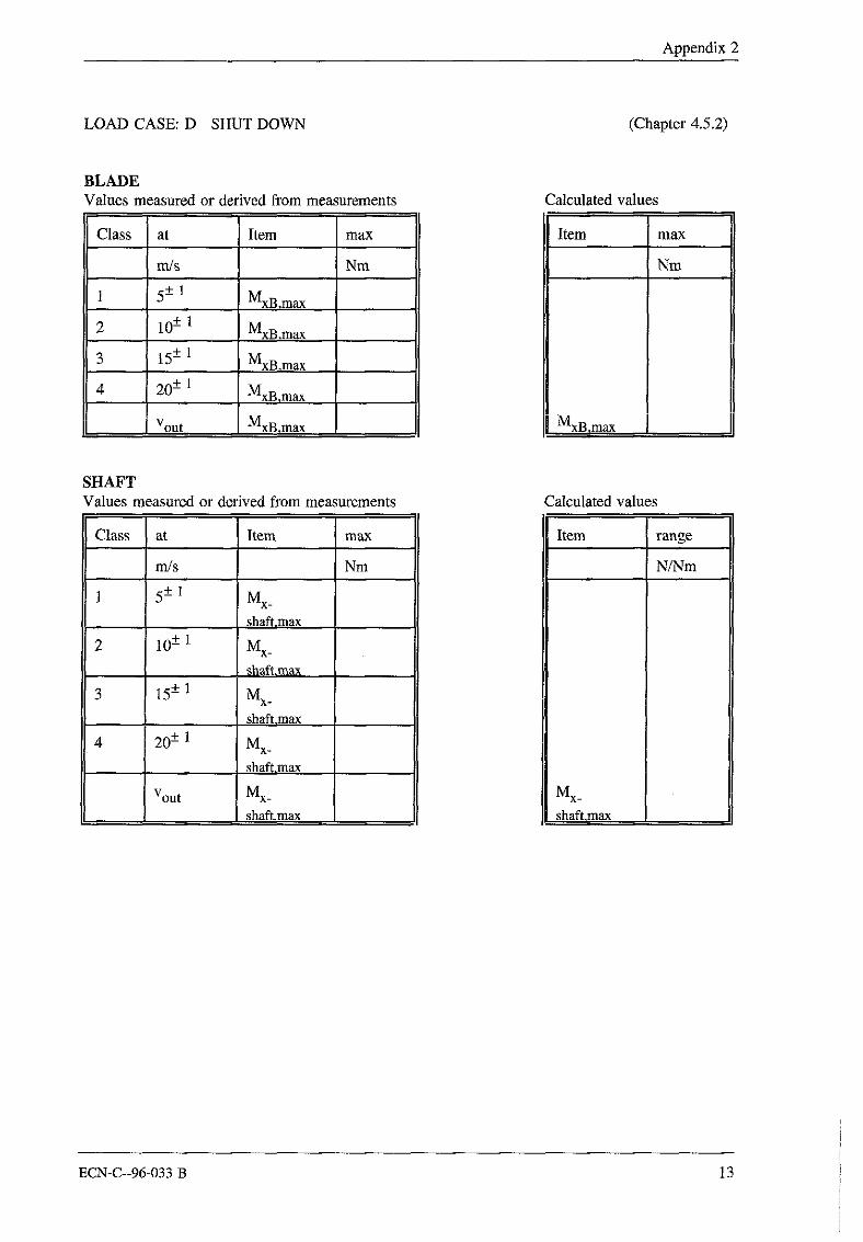
LOAD CASE: D SHUT DOWN (Chapter 4.5.2)
BLADEValues measured or derived from measurements
Class at Item max
m/s Nm
1 5-+ !MxB,max
2 10_+ 1MXB,max
3 15-+ 1MxB,max
4 20_+
Vout MxB,max [
Calculated values
Item max
Sm
MxB,max ]
SHAFTValues measured or derived from measurements
Class at Item max
m!s Nm
1 5+ 1MX_
shaft.max
2 lO+ i MX_
3 15-+ 1 Mx.shaft,max
4 20-+ 1 MX.
Vout MX_
shaft,max
Calculated values
Item range
N/Nm
MX_
ECN-C--96-033 B 13

Verification of design loads for small wind turbines
LOAD CASE: E NORMALLY PARKED (Chapter 4.5.3)
BLADEValues measured or derived from measurements
Class at Item max
m/s Nm
1 5+_ 1 MyB,max
2 10-+ I MvB.max
3 15+ i MyB,max
4 20-+ 1MvB,max
[ ] 1.4 * oo lVXyB,max
Calculated values
Item max
Nm
MyB,max
SHAFTValues measured or derived from measurements
Class from - to Item max
N
1 5-+ 1 Fx-shafLmax
2 10-+ 1 Fx-shafLmax
3 15-+ 1 Fx-shaft,max
4 20± 1Fx-shafLmax
1.4 * 35 Fx-shaft,max
Calculated values
Item max
N
Fx-shafl,max
14 ECN-C--96-033 B

Appendix 2
TOWERValues measured or derived from measurements
Class from- to Item max
m!s Nm
1 5-+ 1 Mb.
bottom,max
2 I0-+ 1 Mb_bottom,max
3 15+ 1 Mb.bottom.max
4 20-+ 1 Mb.bottom.max
1.4 * 35 Mb_bottom,max
Calculated values
Item max
Nm
Mb.bottom.max
LOAD CASE: F PARKED + FAULT
BLADEValues measured or derived from measurements
Class at Item max
Nm
1 5-+ 1 MyB,max
2 10+ 1 MyB,max
3 15_+ 1 MyB ,max
4 20-+ 1 MyB ,max
35 MyB ~max
(Chapter 4.5.3)
Calculated values
Item max
gm
MyB~max
ECN-C--96-033 B 15

Verification of design loads for small wind turbines
SHAFTValues measured or derived from measurements
Class Item max
N
1 5+ 1Fx-shaff,max
2 10+- 1 Fx-shafl,max
3 15+ lFx-shaft,max
4 20+ 1Fx-shafl,max
35 Fx-shaft,max
Calculated values
Item max
N
Fx-shaft,max
TOWERValues measured or derived from measurements
Class at Item max
m/s Nm
1 5+_ 1 Mb_
bottom,max
2 10± 1 Mb_bottom,max
3 15-+ 1 Mb_bottom,max
4 20_+ 1 Mb_bottom.max
35 Mb_bottom.max
Calculated values
Item max
Nm
Mb_bottom.max
16 ECN-C--96-033 B

3. Calibration measured parameters LMW 1003 (CRES)
A1. Blade root bending moment
For the measurement of the blade root flapwise bending moment, a full bridge strain gauge set wasapplied on one of the blades. It was then bolted on the hub and tightened properly so that thetightening remains unchanged during the installation and normal operation.The hub was then mounted in horizontal position and the blade was loaded vertically by moving acertain weight in several distances. The results are shown in Figure 1. This corresponds to a slopeof 0.1 Nrn/mVolt. The offset value was determined setting the blade in vertical position. Both theslope and offset were taken into account in the governing programme of the CR10 data logger.
1 I~01
400
200
000
8OO
600
4OO
I
200 r I r I , 1 , I , I ~
40 60 80 1 O0 120 140 ’~ 61bendlno moment, Nm
Figure 1. Calibration of the blade root bending moment
When the wind turbine was laid down for some necessary repairs, the above procedure wasexecuted once again. The slope was found unchanged, while the offset was significantly different.Therefore, each data set within a relatively short period (some days), should be corrected accordingto the value measured dur’mg calms, when the blade is practically unloaded. This showed to be nota serious problem during data analysis.
ECN-C--96-033 B 17

Verification of design loads for small wind turbines
A2. Tower bottom bending moment
For the tower, the same ~rocedure of the blade calibration was followed as well, while in thebeginning there were plans for on-site calibration using load cells with the tower standing invertical position. The last (bottom) part of the tower was bolted along with it’s steel base plate onthe steel stmctare of the blade test laboratory of CRES. The weight used was 89 kg and thecorresponding results are shown in Figures 2 and 3 for X-fflrecf~on and Y-ff~rection respectively.The latter direction will be set perpendicular to the prevailing wind direction (North) and the toweris expected to be loaded from both sides. Thus, the load was applied to both sides by turning thetower 180 degrees. Negative values of the load distance correspoud to the opposite load’mg. This isnot necessary for the X-direction, since no data from negative loading will be taken into account.
The calculated slopes were 1.60 Nm/mVolt and 1.45 Nm/mVolt in X and Y directions respectively.This was simply taken into account during the data analysis. For the offset on the other hand, asimilar treatment was applied as in the case of blade measurements.
500 :
125O
i 1000
750
1000 1250 1500 1750 2000 2250 250(distance, mm
Figure 2. Tower bending moment calibration in X-direction
18 ECN-C--96-033 B

Appendix 3
1~00
1000
-2000-3000 -2500 -2000 -1500 o1000 -500 0 GO0 1000 t500 2000 ~SO0
distance, mm
Figure 3. Tower bending moment calibration in Y-direction
A3. Yaw position
The yaw position/yaw speed sensor operates on the principle of counting the pulse from a rotaryencoder coupled to the upper part of the W/T. Thus, the number of pulses produced by the rotationencoder is processed by a dedicated microprocessor based converter and two outputs in the form ofan analogue voltage (0-5V) are produced, representing the angle and speed of yawing.
The sensor was calibrated by performing a complete revolution of the upper part of the W/T byhand and noting the maximum output voltage on the position output, just before this outputbecomes zero at the proximity switch. This found to be 2440 mVolts per revolution which is equalto 0.14754 degrees/mV. The above method includes in the calibration the coupling ratio of therotation encoder spindle to the upper part of the wind turbine.
ECN-C--96-033 B 19

Verification of design loads for small wind turbines
20 ECN-C--96-033 B

4. Measurements and calculations Inventus 6 (DEWI).
1. Description of the wind turbine generator system
2. Simplified load calculations according to IEC-TC 88
3. The measurement system
3. i Description of the components for power performance testing1. The Anemometer2. Air temperature sensor3. Measuring transducer module4. The barometer5. Rotational speed6. Data logger
3.2 Description of the components for the load measurement1. Telemetry2. Measurement of yaw angle3. Data acquisition and storing with the MOPS4. Calibration of the wire strain gauges
4. Analysis methods
4.1 Analysis method for power performance testing
4.2 Analysis method for load measurement
5. Measurement results
5.1 Measurement results for power performance testing
5.2 Measurement results for load measurement
5.3 Extrapolation of load measurements
6 Comparison
ECN-C--96-033 B 21

Verification of design loads for small wind turbines
22 ECN-C--96-033 B

Appendix 4
1. Description of the wind turbine generator system
The wind turbine INVENTUS 6 (13) S was built by the manufacturer WENUS Windenergie-Nutzungs-Systeme in D-50374 Erftstadt. It is designed for a rated electrical power of 5 kWat a rated wind speed of 10.5 m/s. The rotor is composed of four blades working with highspeed on the windward side.The wind turbine is working with a rotary current generator system that can be used in twodifferent power stages. The first power stage is layed out for a generator speed of 1000 min"~and produces a maximum electrical power of 1.5 kW. The second power stage is layed outfor a generator speed of 1500 min4 and produces a maximum electrical power of 5 kW.The generator is working as a three-phase asynchronous generator.The control system of the wind turbine is put in place on a board where all important signalscome in.A thauroductor is scanning the generator speed. This signal is evaluated in the control systemso that the generator can be switched into the right power stage. For this steering thefollowing p~,ueters have been chosen:At a generator speed less than 1000 miff1 the machine is running with no load. When thisvalue is stepped over the first power stage is switched. At a generator speed of I084 mifftthe rated power of 1.5 kW in this stage is reached. If the generator speed is increasing about1100 miff~ (10% slip), for longer than 20 seconds, the first power stage is disconnected fromthe net. With no load the generator is running up to 1500 rain1 fastly. At this speed thesecond power stage is switched on. In this power stage a slip of 10% can also be used. So themechanical control system is able to use a generator speed up to 1650 rain"I. The rated powerof the wind turbine is reached at a generator speed of 1556 miff~. If the generator speeddecreases under 1500 min~ for longer than 20 seconds, the second power stage is switchedoff and the first power stage is switched. So the generator speed is reduced to 1000-1100rain"~.The wind turbine has a gearing with a transmission of 1:12,11. According to the rotor speedthe following parameters result:¯ At a rotor speed of 83 rain~ the first power stage is switched on. The INVENTUS 6
reaches this speed at a wind speed of 3.5 m/s.¯ The rated power of 1.5 kW in this power stage is reached at a rotor speed of 89 min~.¯ If the rotor speed surpasses 91 miff~, the first power stage is switched off(at about 7 m/s).¯ At a rotor speed of about 124 raina the second power stage is switched on.* The generator reaches it’ s rated power of 5 kW in the second power stage at 128 mifft (at
about 10.5 m/s).* If the rotor speed decreases under 124 raint the second power stage is switched off and
the first power stage is switched on.
The switching of the both power stages is effected by two rotary current contactors.
The power delimitation of the turbine is effected by the mechanical blade adjustment(passive). This kind of power delimitation is called c~ - regulation. This regulation uses theaerodynamik forces to adjust the blades. To realize this the INVENTUS 6 shows aconstructive peculiarity: In the top view the longitudinal axis is positioned with an acuteangle to the regulation axis of the blade (fig. 1.1). Looking in the sense of rotation theresulting straining point is positioned behind the regulation axis of the blade.Because of this arrangement the aerodynamik forces produce an adjusting moment that turnsthe blades into feathering position. With raising wind speed the lift forces and the resultingadjust moment are reduced through an increasing of the pitch angle of the blade. In contrast
ECN-C--96-033 B 23

Verification of design loads for small wind turbines
to this the driving force and according to this the usable moment and the power of the rotorstay constant.
regulating straining point llne
~*~result’ straining point
regulating systemas a disc cam gear
Fig. 1.1: Constructive conditions for the a - regulation
Fig. 1.2: Mechanical blade adjustment
To rotate the turbine in the wind direction the INVENTUS 6 is equipped with a wind vane.The vane is a sandwich construction, which consists of the natural basic substance straw and
24 ECN-C--96-033 B

Appendix 4
was developped at the Wilhelm-Klauditz-Institute by the work group for wood research. Ithas a surface of 2.34 mz and weighs only about 20 kg.
To protect the wind turbine against large loads caused by vibrations the turbine is equippedwith a contact that reacts on vibrations. This contact is triggered through a verticalsuspended weight that reacts on strong vibrations or rollings of the wind turbine. When theswitch comes into action a defined current activates the fault current breaker which seperatesthe wind turbine generator system from the net. Because of this disconnection the disk brakeis activated. The rotor of the turbine is braked through the braking moment which isadjustable by springs.
weight
~~switcherfastening~--’~o I
~ b"--a~’~ cable ushing
Fig. 1.3: Vibration switch
The brake can only be loosened when the fault current braker is disactivated manually. At theINVENTUS 6 the release position of the brake is hold by air pressure. When the wind turbineis connected to the net a magnetic valve is opened that lets air pressure flow into a cylinder.This cylinder releases the brake linings against the spring pressure from the disk.
The INVENTUS is equipped with a three-parted hot galvanized tower made of steel with adiameter of 168.3 mm. The tower is spannend by four wires made of steel. By means of ahandling winch the wind turbine can be layed down easily. To put the turbine up, more strainis needed because of the high moment of the crank handle. With a stronger handling winchthat was installed this work could be made easier.
ECN-C--96-033 B 25
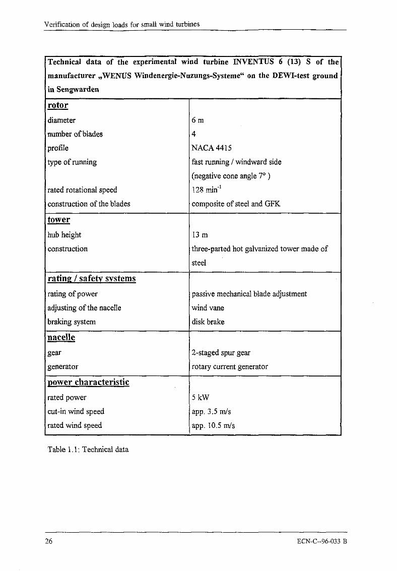
Verification of design loads for small wind turbines
Technical data of the experimental wind turbine INVENTUS 6 (13) S of the
manufacturer ,,WENUS Windenergie-Nuzungs-Systeme" on the DEWI-test ground
in Sengwarden
rotor
diameter 6m
number of blades 4
profile NACA 4415
type of running fast running / windward side
(negative cone angle 7° )
rated rotational speed !28 _m_~nq
construction of the blades composite of steel and GFK
towe._.__E
hub height 13 m
construction three-parted hot galvanized tower made of
steel
rating / safety systems
rating of power passive mechanicalblade a~ustment
adjusting of the nacelle wind vane
braking system diskbrake
nacelle
gear 2-staged spur gear
generator rotary cu~ent generator
power characteristic
rated power 5kW
cut-in wind speed app. 3.5 m/s
rated wind speed app. 10.5 m/s
Table 1.1: Technical data
26 ECN-C--96-033 B

Appendix 4
2. Simplified load calculations according to IEC-TC 88
The loads which are effective on the INVENTUS 6 are calculated according to the IEC-TC88 method. The necessary entry data are taken from the manufacturers manual, if notmentioned otherwise.
Entry data ( based on the manufacturer’s manual )
B
M~k¢
Cd,hood
Aproj,h
Cdcotor
Cd~vane
Bf
rotor radius 3 mrotor speed at rated wind speed (stage 1 / 2) 89/128 rpmrated wind speed 10.5 m/srated power 5 kWefficiency (assumed value) 0.8mass of one blade 12 kgdistance from the center of gravity of a blade to theblade root - hub junction 0.986 mnumber of blades 4distance from rotor center of gravity to first beating 0.15 mmaximum angular rate of yawing (assumed value) 1 rad/sdistance between rotor and tower centre 0.7 mblade moment of inertia 26 kg* m2
maximum speed of the rotor 179 rpmmass of the rotor 75 kgdistance from the center of gravity of the rotor to therotation axisnominal torque of mechanical brakedensity of airreference 50 years wind speed at hub heightdrag coefficient of the hoodhood section area projected on a plane perpendicular tothe wind direction 0.14 m2drag coefficient of the rotor 1.5rotor section area projected on a plane perpendicular tothe wind direction 4 * 0.69 mzdrag coefficient of the tower 0.7diameter of the tower 168.3 mmtower section area projected 0n a plane perpendicular tothe wind direction, 2.184 m2
section area of the vane (crosswise to the winddirection)2.335 m2drag coefficient of the vane (crosswise to the winddir. )1.5
section area of the vane der Fahne (in wind dir.) 0.192 mdrag coefficient of the vane (in wind dir.) 0.01 4)gust factor 1.4
0.003 m1816.5 Nm ~1.225 kgim3
1.4 * 35 rrds1.3
this value is related to the measurement position on the rotorblade, to allow a comparisonto the reference dimension (see the following figures)the real nominal torque of the brake is 150 Nm. Through the gear ratio of 1:12.tl thistorque is increased to1816.5 Nm.this area results from an average thickness of 89 mm and an average height of 2.15 m.estimated value
ECN-C-o96-033 B 27

Verification of design loads for small wind turbines
The following picture shows the dimensions of the rotorblades, used in the calculations:
Fig. 2.1: Rotorblade with the distances of center of gravity
rotorblade, complete axes blade without axescenter of gravity SG SB Ss
mass mG = 12 kg mB= 2,56 m ms = 9,44 mcenter of gravity r~ = 1,266 m rB = 0,39 m rs = 1,503 mradius
Table 2.1: Masses and distances at the rotor blade
7.27
Fig. 2.2: Measuring position at the blade root
28 ECN-C--96-033 B

Appendix 4
results- results- results- results-manu- measured measured measured
Load location kind of load facturer values 1 values 2 values 3ease (5.0 kW at (4.2 kW at (3.0 kW at (4.8 kW at
10.5 m/s) 15 m/s) 13 m/s) 12 m/s),A 3.83 2.68 3.09 3.35
QR 466 Nm 392 Nm 280 Nm 448 Nmblade root loads 4252 N 4252N 4252N 4252 N
349 Nm 330 Nm 302Nm 344 Nm446Nm 263 Nm 216 Nm 375Nm
rotorshaff loads 893N 525N 433N 750 N466Nm 392 Nm 280Nm 448Nm667Nm 483 Nm 437 Nm 596Nm
B blade root loads 705Nm 705 Nm 705Nm 7O5Nmrotorshaff loads M b-shatl, m~x 1951Nm 1767Nm 1721Nm 1879 Nm
C blade root loads F2~,]I~ 4157 N 4157 N 4157 N 4157 Nrotorshaft loads Mb-~aa, max 122Nm 122Nm 122Nm 122 Nm
D rotorshaft loads M x-shafi, m~x 2283 Nm 2208 Nm 2096 Nm 2264 Nm
blade root loads 687Nm 668Nm 640Nm 682Nm
E hub Fhub(l,4) 268 N 268 N 268 N 268 Nrotor Frotot(1,4) 6088 N 6088N 6088 N 6088Nnacelle Fnae¢lle(l.4) 6356 N 6356 N 6356 N 6356 Ntower Ftow~l,4) 1147 1147N 1147 N 1147Nvane 58 N 58 N 58 N 58 N
F hub Fhub 137 N 137 N 137N 137 Nrotor ~rotor 3106 N 3106 N 3106 N 3106 Nnacelle Fnac¢lle 3243 N 3243 N 3243 N 3243 NtoweF F~owgr 1147 N 1147 N 1147 N 1147 Nvane 1227 N 1227 N 1227 N 1227 N
Tab. 2.2: Calculation results
Stress calculation
¯ In this chapter the stresses are calculated which are resulting from the forces and momentslisted in table 2.2. The calculations are executed for the positions where the measurements ofthe loads are done (except for the rotor shaft).
¯ The tensile strength in the pitch rod can only be measured with the help of the manufacturersdata, because in the international standard IEC 88 no mathematical notations are specified forthis special case. The same problem appears when the mechanical tension of the tower at themeasuring point shall be calculated. The calculation is done with the thrust force in the rotorshaft given from the manufacturer at rated wind speed.
ECN-C--96-033 B 29
Verifiea~lon of design loads for small wind turbines
¯ For the load case A ( normal operation ) no absolute stresses can be calculated, because theIEC-TC 88 outline just gives mathematical formulars for the ranges of the forces / moments.Nevertheless a comparison with the measured values is possible, because the measured timeseries allow to indicate both absolute forces / moments and ranges of the forces / moments.
¯ The loads resulting for load case C ( loss of electrical load ) are not converted into stressesbecause this load case can not appear at the INVENTUS 6 and so a comparison withmeasured values is impossible. In the IEC standard it is assumed for the load case C that themaximum speed of the rotor results when the generator and the rotor are not breaked by thenet anymore. In case of loss of electrical load the brake of the INVENTUS 6 is activatedautomatically. The conclusion is that load case C has the same effect as load case D ( shutdown ).
¯ For the load cases E and F the stresses in the blade root and in the measuring point of thetower are converted from the aerodynamic forces that act on the rotor, the nacelle and thetower ( above the measuring point ).
necessary_ data:
¯ material of the blade root axis:outside diameter D:inside diameter d:cross-sectional area A:section modulus Wb:elastic modulus E:tensile strength I~:material of the rotor shaft:diameter of the rotor shaft D:cross-sectional area A:section modulus Wb:elastic modulus E:tensile strength 1%:
¯ material of the tower:outside diameter D:inside diameter d:cross-sectional area A:section modulus Weelastic modulus E:tensile strength 1%:thrust force in the rotor shall ( at VR )distance nacelle-measuring point 1 at tower:bending moment ( Fr-I )wind force ~tower;,2,82(l,4):
wind force Ftowo~,z82:¯ material of the pitch rod:
cross-sectional area A:maximum force of load F~x:elastic modulus E:tensile strength 1%:
precision steel (DIN 2391) St 3545 mm37mm515 mm24857 mm~2.1-10~ N/mm~330-470 N/ram2C 4555 mm2376 mmz16334 mm32.1-10~ N/ram2
630-780 N/mm2
steel tube R St 37-2168.3 mm160.3 mm2065 mm282839 mm32.1 - 10~ N/mm~
340-470 N/mm21168 N2.82 m3854 Nm489 N ( above measuring point )250 N ( above measuring point )St 3764 mm2945 N (at 10 rrgs )2.1-10~ N/mm~370 N/ram~
30 ECN-C--96-033 B

Appendix 4
Stresses that result from given moments are calculated by the equation
Stresses that result from given forces are calculated by the equationF
Load case A:
Load case location kind of load stressesA blade root AFa = 4252N tensile stress = 8.3 N/mmz
AM~ = 349Nm bending stress = 71.9 N/mm2
L~’v~ = 446Nm bending stress = 91.9 Nimm"rotor shaR AFx_,ha~ = 893N tensile stress = 0.4 N/ramz
AMx_~,,~l, = 466Nm torsional stress = 28.6 N/mm2
AMy_,~ = 667Nm bending stress = 40.9 N/mm2
.’alculated tensions at the blade root and at the rotor sha,~:
Tab. 2.3: Stresses at the blade root and at the rotor shaft ( Load case A )
Calculation of the bending moment at the mast:
A) with values of the manufacturer; at rated wind speedAssumption: the upper part &the spanning does not strengthen the mast strongly.
bending moment:section modulus:
mechanical stress:
Mr, = Fr¯ l = 1168N. 2,82m = 3294Nm
32 D 32 168,3mm
o" ="-~-~ =M~ 3294-82839mm310~Nmm = 39,SN/mm2
B) Calculation with the range of the thrust force in the rotor shaft
bending moment:
mechanical stress:M~ = AF~_~,yt- l = 893N. 2,82m = 2519Nm
~y = M~W~ = 2519.82839mm310~Nmm = 30,4N/ram~
Calculation of the tensile stress in the pitch rod (at rated wind speed):
945Ntensile stress: o- = = 14,8N / mm’-64mm’-
ECN-C--96-033 B 31

Verification of desi~ma loads for small wind turbines
Load case B:
In this load case just the largest flapwise bending moment that is caused by yawing is takeninto account. The bending stress in the rotor shaft is converted from the bending moment inthe rotor shall caused by yawing.The other forces are small and can be assumed as zero.The bending stress of the mast is not calculated in this load case because the nacelle does notexert a defined load on the measuring point of the mast.
load case location kind of load stressesB blade root MvB.max=705 Nm bending stress= 145.2 N/mm2
!rotor shaft M~ha~,max=1951 Nm bending stress=119.5 N/mm2
Tab. 2.4: Stresses in the blade root and in the rotor shaft ( load case B )
Load caseD:
In this load case the torsional stress in the rotor shaft is calculated wich results of themaximum braking moment.The bending stress in the blade root is also effected by the braking moment.It is assumed that the other forces and moments are not that important in this load case andcan be neglected.
load case location kind of load stressesD blade root Mx~,m~x=687 Nm bending stress=141.5 N/mm2
rotor shaft Mx-sha~.max=1951 Nm torsional stress= 139.8 N/mmz
Tab. 2.5: Stresses at the blade root and at the rotor shaft ( load case D )
Load case E:
The bending stress at the blade root is calculated from the wind force that effects the wholerotor. In this load case the wind turbine is standing still and so it is assumed that the windforce acting on the rotor is concentrating in the center of area of each blade.The distance from the center of area of one blade to the measuring point is resulting from:
1.35 m - 0.227 m - 0.064 m = 0.949 mThe bending stress of the mast is converted from the the wind forces that act on the hood, thenacelle, the wind vane and the tower ( above the measuring point ). It is assumed again thatthe upper part of the spanning does not strengthen the tower very much.
Calculation of the bending stress at the blade root:
bending moment: 1
1Mb = 6088N.-. 0.949m = 1444.4Nm
4
32 ECN-C--96-033 B

Appendix 4
bending stress:1444.4.103 Nmm
= 298N / mm24857turn3
Calculation of the bending stress at the mast:
bending moment:
bending stress:Mb = (268N + 6088N + 489N + 58N). 2.82m = 19467Nm
~r = A4b - 19467*103Nmm 235N/ram~82839mm3
Load case F:
The bending stress at the blade root is calculated from the wind force that effects the wholerotor. In this load case the wind turbine is standing still and so it is assumed that the windforce acting on the rotor is concentrating in the center of area of each blade.The bending stress of the mast is converted from the the wind forces that act on the hood, thenacelle, the wind vane and the tower ( above the measuring point ). It is assumed again thatthe upper part of the spanning does not strengthen the tower very much.
Calculation of the bending stress at the blade root:
bending moment:
bending stress:
Mb = 3106N---". 0.949m = 736.9Nm4
736.9.103 Nmm= 152N / mm2
4857mm3
Calculation of the bending stress at the mast:
bending moment:
bending stress:
Mb :(Fhub ~-Frotor ~t-Fto~r2.82 +F~..).2.82m
M~ = (137N + 3106N + 250N + 1227N). 2.82m = 13310.4Nm
M~ 13310.4*103Nmm161N /mm~
82839mm3
ECN-C--96-033 B 33
Verification of design loads for small wind turbines
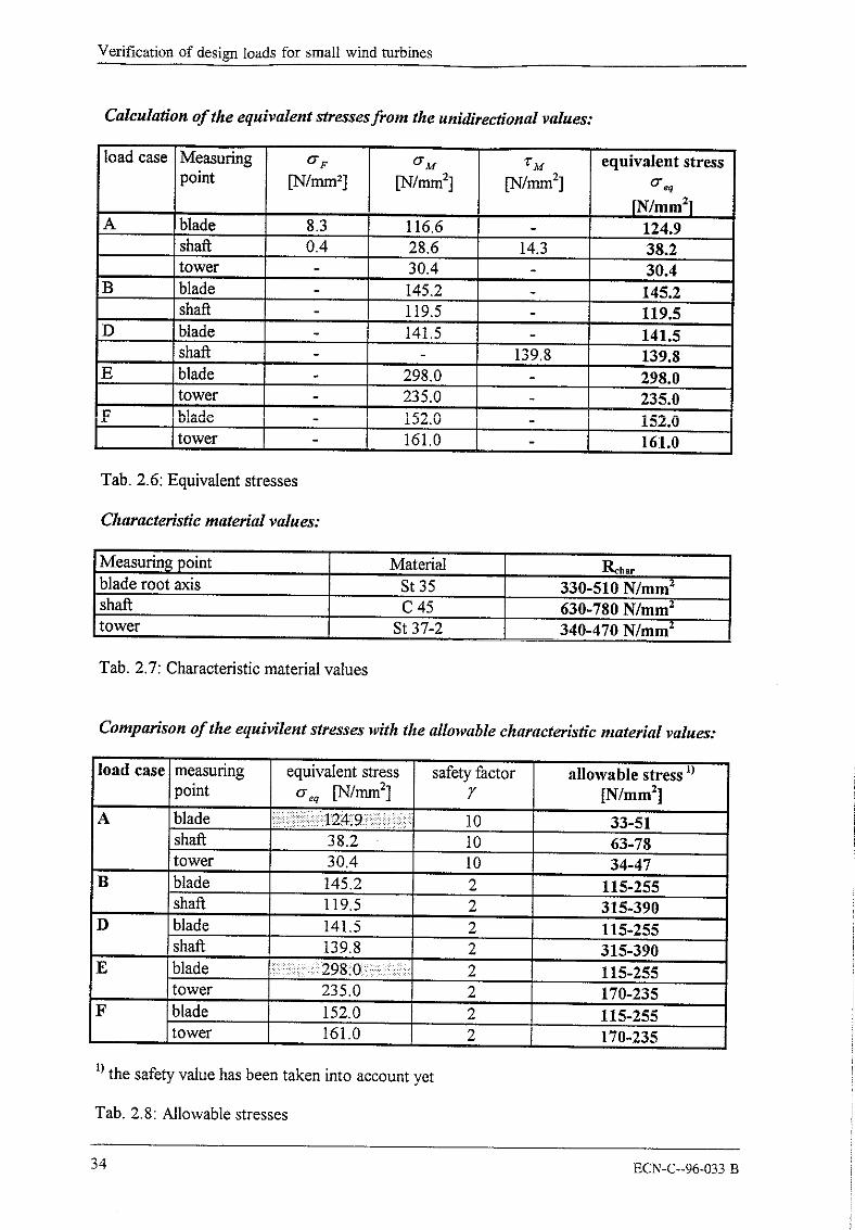
Calculation of the equivalent stresses from the unidirectional values:
load case Measuring O"F O"M TM equivalent stresspoint [~lmm~] 0"2
[N/mm2]A blade 8.3 116.6 124.9
shaft 0.4 28.6 14.3 38.2tower 30.4 30.4
B ! blade 145.2 145.2shaft 119.5 119.5
D blade 141.5 141.5shaft 139.8 139.8
E blade 298.0 298.0tower 235.0 235.0
F blade 152.0 152.0tower 161.0 161.0
Tab. 2.6: Equivalent stresses
Characteristic material values:
Measurin~ point Material Rchar
blade root axis st 35 330-510 N/mmzshaft C 45 630-780N/mm2tower St 37-2 340-470N/mm2
Tab. 2.7: Characteristic material values
Comparison of the equivilent stresses with the allowable characteristic material values:
load case measuring equivalent stress safety factor allowable stresspoint o-eq ~/mm21 7 [N/mm:]
A blade 10 33-51shaft 38.2 10 63-78tower 30.4 10 34-47
B blade 145.2 2 115-255shaft 119.5 2 315-390
D blade 141.5 2 115-255shaft 139.8 2 315-390
E blade 2 115-255tower 235.0 2 170-235
F blade 152.0 2 115-255tower 161.0 2 170-235
1) the safety value has been taken into account yet
Tab. 2.8: Allowable stresses
34 ECN-C--96-033 B

Appendix 4
The table shows that nearly all equivalent stresses are smaller than the allowable stresses,except for the equivalent stresses at the blade root axis in the load cases A and E.But it has to be taken into account that the influence of the pitch rod wich contains a part ofthe flapwise bending moment is not taken into consideration.The equivalent stress at the tower in load case E are placed on the upper level of theallowable stress range.
ECN-C--96-033 B 35

Verification of design loads for small wind turbines
3. The measurement system
3.1 Description of the components for power performance testing
The wind speed at the hub height of 13m is measured with a cup anemometer, constructed bythe firm "A. Thies GmbH & Co". The used anemometer was calibrated in the wind tunnel atthe University of Oldenburg before usage.The wind direction is measured at DEWI’s meteorological tower app. 150m far away fromthe turbine at a height of 40m.The performance data is accuired by a measuring transducer module (C. Thiim) according toIEC 688 and transformed into a current between -213 mA and +20 mA.For air density correction, the temperature was measured at a height of 10m with a sensor ofthe firm "A. Thies GmbH & Co". The alrpressure is measured by a sylphon bellows of theaneroid barometer.All these parameters are recorded by a data logger (Ammonit) with a sample rate of 1 Hz andare stored as 5-minutes-averages, together with maximum, minimum and standard deviationfor wind speed, rotational speed and power. The memory of the data logger can be read outby a computer.
3.1.1 The Anemometer
The wind speed sensor constructed by "A.Thies GmbH & Co" is able to measure wind speedsbetween 0.3 and 40 m/s. It consists of three parts: housing, plug and cups.The cups are put into rotation by the wind and the rotational speed is measured by a opticdevice. According to the wind speed depending rotational speed a electric frequency iscreated (squarewavesignal 0-14 V). Wind speed and frequency have a linear dependance,determined during calibration in the wind tunnel. The minimum wind speed for rotation is 0.3m/s and the maximum windload is 60 m/s. The device weighs one kilo and is allowed to beoperated at temperatures between -35°C and +60°C. It has a heating to avoid freezing of thebearings.
Fig. 3. I: Cup anemometer
36 ECN-C--96-033 B

Appendix 4
3.1.2 Air temperature sensor
The air temperature sensor is capsuled against weather and beams so only the air temperatureis measured. In contrary to uncapsuled sensors this sensor is protected against rain andsunbeams.The implemented temperature depending resistor (PT100) according to DIN 43760 ischanging its resistance according to the actual temperature. It should be used in fourwiresystems to avoid faults because of wire resistances. The device has a weight of 0.8 kg and aprecision of 1/3 DIN permissible variation ( 0.1° C at 0° C ).
Fig. 3.2: Air temperature sensor
3.1.3 Measuring transducer module
Function:The input transformers for voltage and current seperates the inputs galvanlcly from theconverter. The signals are amplified to suitable levels and led to the multiplyer. Themultiplication is made by changing the current signal to a pulse with modulation of a squarewave, and the voltage signal to an amplitude factor for the squarewavesignal, thus giving apulse area equal to the actual momentary power. Using a high frequency for the square pulsesensures an accurate measurement even with a high grade of curve distortion. The results fromthe multiplyer pass an active filter and an output circuit to ensure a low ripple and stableoutput signal. Output signals are shortcirquit and opencircuit proof.Further specifications
Input-nominal voltage:-input resistance:-nominal current:-max input:
110...660 V300 - 500 kOhm1 A (from.../1 A current transformer)inom. x2 constantinom. xl0 for 10 sec.
-input resistance: 50 mr2
ECN-C--96-033 B 37

Verification of design loads for small wind turbines
Output-precision:-linearity:-response time:-supply dependence:-temp. dependence:-ripple:
class 0.5<0,1%< 200 msec.< _+0,01% / % U supply< _+0,02 % / °C<lpp
The output current has to be changed into a voltage, because the used data logger is only ableto read voltage signals (range from 0... 1200 mV; 600 mV means 0 kW).
3.1.4 The barometer
The passive barometer measures the actual air pressure of the surrounding. This measuredvalue is shown on the scale and can be transponded as a electrical signal. The airpressure ismeasured by a sylphon bellows of the aneroid barometer, who’s ai~ressure depending travdis changing the resistance of a potentiometer. This resistance is a quantity for the actual airpressure. The barometer has to be configured to the placeheight through reducing themeasured pressure to sea level. The maximum measurment range is 945... 1052 hPa within areliability of 1.5% of the measuring range. This device weighs 0.7 kilos and is allowed to beoperated at temperatures between -20°C and +60°C.To use this barometer in combination with the data logger, an adaptation mounting had to beconstructed, because this datalogger accepts only active barometers.
Epotentiom~ter
pointer
Fig. 3.3: Barometer
3.1.5 Rotational speed
The rotational speed signal was taken from the thauroduktor signal of the converters controlsystem. The signal is decoupled by a operational amplifier and an optoelectr.onlc coupler toavoid an electrical load. This signal is, together with the two power state signals, decoupledby two relays, lead to the new switch box at the bottom of the turbine and further to theevaluation device.
38 ECN-C--96-033 B
Appendix 4
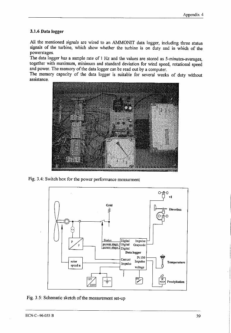
3.1.6 Data logger
All the mentioned signals are wired to an AMMONIT data logger, including three statussignals of the turbine, which show whether the turbine is on duty and in which of thepowerstages.The data logger has a sample rate of 1 Hz and the values are stored as 5-minutes-averages,together with maximum, minimum and standard deviation for wind speed, rotational speedand power. The memory of the data logger can be read out by a computer.The memory capacity of the data logger is suitable for several weeks of duty withoutassistance.
Fig. 3.4: Switch box for the power performance measurment
Grid
Digital ImpulseDigital Cn’aycodeDigital
Data logger
Current ImpulseImpulse
voltage
Temperature
Fig. 3.5: Schematic sketch of the measurement set-up
ECN-C--96-033 B 39

Verification of design loads for small wind turbines
3.2. Description of the components for the load measurement
3.2.1 Telemetry
To make it possible to mn the telemetry in continuous operation a transformation of powersupply into the rotating system had to be realized. Therefore a slip ring mounted on the rotoraxle and a carbon brush mounted on the nacelle were constructed (see figure 3.6). Bothgalvanically seperated from the nacelle and rotor are transporting the current to the telemetry.The cirquit is closed by using the metal rotor bearing and the nacelle. The wiring is realizedby pulling a new cable through the tower which leads to a power pack. This power packdelivers an adjustable direkt current.
Design of the telemetryThe telemetry (Volland telemetry) consists of several modules to guarantee a light weight andsmall volume. It delivers a very stable current for the module supply (temperaturedependency: 0,002 %/°C). This current can be adjusted from +1.5 V to +5 V. During thismeasurement a voltage of 3.5 V was used. The telemetry is supplied by a power supply thatis positioned in the container.
Fig. 3.6: Slip ring with brush
Wire strain gauges amplifierThe amplifier is characterized by its high precision, its small temperature dependency and itssmall power consumption. The module consists of 8 constant voltage strain gauge amplifiers,whose gain factors were adjusted by the manufacturer. But it is possible to choose betweenfour equal ( V = 1000 ) and four different ( V = 100, 200, 400 and 800 ) gain factors. Theconnection of the wire strain gauges is a full bridge.
40 ECN-C--96-033 B

Appendix
Technical values:
Gain factors 100, 200, 400, 800, 4~1000Direct impedance s ME~
Band width 100 kHzTemperature dependency 0.002 % /°C
Nonlinearit~ 0.01%Current consumption 0.4 mA
Tab. 3.1: Technical data of the wire strain gauges amplifier
Front-end filter:The front-end filter is a low-pass with a special characteristic. It is used to limitate the signalfrequencies in multichannel-multiplexer systems as for example PCM-data logger systems. Itis topped on the input amplifier. Its limitting frequency at 3 dB disadvantage of the outputsignal is 37.5 - i200 i-iz ( dependent on the type ). All frequencies higher than the limittingfrequency are extracted,
ControllerThe signal is transformed into impulses by the PCM-controller ( pulse-code-modulation ).Afterwards the height of the impulses is determined by a comparison measurement andconverted into a sequence of binary numbers ( binary code ) which then is transfered. So theheight of the impulse, analogue to the transfered signal, is converted into digital values. Adigital combination of codes in the binary system which consists of two possible states can betransmitted without essential disturbances. In this way errors in the transmission are avoided.The precision of the PCM-controller is 12 bit which means that the signal is parted into 212steps ( 4096 binary steps ). A so called quantification characteristic line results from this.The used PCM-controller has a potentional range of+_ 10,24 V ( AU = 20,48 V ). Using a12-bit scan ( 4096 steps ), every step is coded in 5 mV.The first bit is giving the sign of the voltage. It is formed a frame adress which consists of thevoltage impulse (measurement signal) and the synchronization-word. The decoder issynchronized by the synchronization-word and gets irnformation about data which may belost during the transmission.
HF-transmitterThe I-IF-transmitter was manufactured by Acra Control LTD, DublinType:SAM/RFT/002/433920/0080/010m It is using a data transfer rate of 80 kbit / sec, at atransmitting power of 10 mW. It’s transmitting at a frequency of 433.92 Mhz.
AccumulatorThe 12 V accumulator has a capacity of 2.8 Ah. It is just used as a buffer battery to excludeinfluences caused by fluctuations or ripples of the power supply.
IR-Remote controlDuring this measurements a infrared remote control consisting of the receiving- andtransmitting circuit board ,,IF 529fie 532" of the manufacturer Vielstedter Elektronik wasused to switch the shunts for the calibration procedure. The transmitter, equipped with a lensto expand its range, wa put in place in a hand case. The receiving circuit board is put in placein one of the telemetry boxes together with the accumulator.
ECN-C--96-033 B 41

Verification of design loads for small wind turbines
3.2.2 Measurement of yaw angle
A further innovation was a yaw angle transmitting device mounting, which is in the conditionto equalize the swinging of the nacelle. It has a spring allowing the transmitting device tomove relative to the tower.
Fig. 3.7: Yaw angle transmitting device mounting
The absolute pulse donator for the measurement of the yaw angle was manufacturered byMegatron, Munich and was used at the !NVENTUS 6 for the measuring of the yaw angle.The used device ( type M500 ) is a 12-bit optoelectric pulse donator with gray-code.
resolutionlimiting frequencycode)ower supplyoutput signalmaximum axis loadsoperation temperature
12 bit / 360°100 kHzgray-code+5 V DC (+5 % )squarewave signal ( TTL and CMOS compatible150 N, axial and radial-20° C to +70° C
Tab. 3.2: Technical data of the pulse donator
3.2.3 Data acquisition and storing with the MOPS
All measured data are recorded by the MOPS (MOdular Processor controlled Signalacqusifion device). The MOPS is constructed by CAESAR-Datensysteme. This compactsignal acquisition device is, as the name annouces, made modular, i.e. that it is compoundedfrom various exchangeable modules to be able to adapt it to various demands.The base device consists ofa busboard which offers 10 slots. Three slots are occupied withthe power pack, the CPU and a CTR card (programmable scancontrol unit with pc-interface).
42 ECN-C--96-033 B

Appendix 4
For this measurement the following configuration was used:
MAD card to coilect analogue signals by an input multiplexer with an A/D converter(16 channels per MOPS card)technical data: resolution
error limitlinearity distortionscanning frequencymax excitation voltagemax excitation currentinput range
12 bit< 1 LSB< 0.5 LSBprogrammable, max. 128 kHz+ 15 volts+40 mA+ 10 volts 5 MOhm
¯ DIO card for measuring and outputting of digital states with optic state indication(signallevel TTL or by optoelectronic coupler). There are two channels per card availablewith a resolution of 16 bit
¯ PIM card for the- fast data transfer between PC and MOPS for the nominal data transition- data transfer from an external PCM-interface into the MOPS system, mixingwith other channels
- synchronization of several PCM-Interfaces- elimination of syncloss errors while using telemety or DAT- slave-synchronization of the acquisition- and output devices of the MOPS
¯ VFM-card which allows to filter 4 channels by a analogue low-pass filter whose limitfrequency is programmable. This filter offers various characteristics and can be used forthe limitation of the band width, e.g. to reduce the noise level
¯ lPZ-card which is able to do twocharme! impulse counting
Furthermore three isolating amplifierers for the analogue signals were installed.
The measurement programme was controlled by an integrated PC with a software calledTormrDAC. The data is stored on an external harddisk with a capacity of 2 Gbytes. Notevery time series of 1 minute is stored, but only those which are necessary to fit the matrix oris triggered by a special event, see chapter 4.2.
3.2.4 Calibration of the wire strain gauges
The aim was to calibrate the wire strain gauges without laying down the wind turbine. Asexperience shows, the linearity of the wire strain gauges is not degrading during usage.Therefore only two points have to be determined to get a compensating curve.To get the first point a position has to be defined in which the wire strain gauge is nearly inan mechanical loadfree position. The second point is available through a defined irritation ofthis gauge. To reach this, every gauge gets a shunt, i.e. a very exact calibration resistor,mounted parallel to one of the legs of the gauge, with the possibility to switch it on and off. A1MI2 resistor (0.1% precision) was used. After calibration, the shunts can be switched offand the measurement can start.
ECN-C--96-033 B 43

Verification of design loads for small wind turbines
To switch the shunts on and offa remote control and a receiver board was used, so it was nolonger necessary to lay the wind turbine down during calibration. Each wire strain gauge gotone calibration resistor switched parallel for calibration by each a relay.Because of the special mounting with respect to the rotorblades, the INVENTUS 6 has anegative coning angle of 7°, so the rotor system never takes a place in which the measuredblade is nearly in a mechanical loadfree position.In respect to this two rotor positions were taken, one with the measured blade right up andthe other with the blade hanging right down. For this way of calibration, it was required torelease the brake without starting the operational system (every manual start of theINVENTUS 6 lets the generator work as a motor for a few seconds). Therefore a switchexists in the swiching box at the bottom of the tower, which allows to release the brakes withan external current. So the rotor starts slowly rotating (provided, that there is any wind), andthe brakes can be activated when the correct rotor position is reached. The average value ofboth measurments was treated as an acceptable zero level. In spite of the very calm windconditions during the calibration procedure (v ~ 3 m/s), the nacelle was turned crosswise tothe wind direction to avoid any wind influence. Through this procedure, two mean values(with and without connected shunt) were derived for every primary element and acompensating curve could be described for the three parameters edge- and flapwise momentand force in the pitch rod.
Arrangements for the calibration procedure
The calibration of the measuring points serves to find the relation between the measured andthe real reference dimension. The used principle of shunt calibration fullfills nearly the samepurpose as the calibration done earlier with the help of several weights. The only differenceis, that the needed calibration forces are not caused by weights, but are simulated by theswitched shunts. So there is no need to lay the wind turbine down for calibration.
The following configuration was defined for the sign of the strain direction:
¯ a positive flapwise moment occurs if the rotorblade is bend leewards¯ a positive edgewise moment occurs if the generator moment is also positive¯ the force in the pitch rod is taken positive if there is a tensile strength.¯ the reference dimension for the "north-south" wire strain gauge of the tower gets positive
if the tower is bended northwards.¯ the reference dimension for the "east-west" wire strain gauge of the tower gets positive if
the tower is bended eastwards.
It is important to mention that "N-S" and "E-W" do not correspond to real north direction,but to the following configuration:
44 ECN-C--96-033 B
Appendix 4
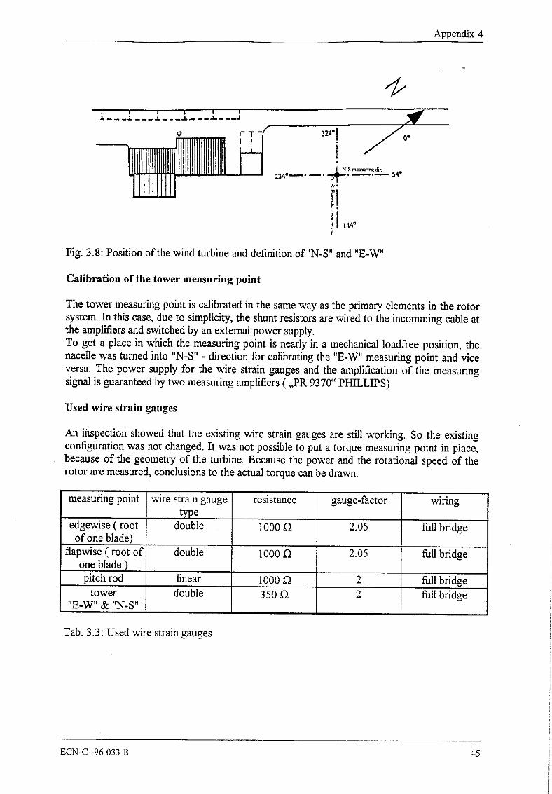
Fig. 3.8: Position of the wind turbine and definition of"N-S" and "E-W"
Calibration of the tower measuring point
The tower measuring point is calibrated in the same way as the primary elements in the rotorsystem. In this case, due to simplicity, the shunt resistors are wired to the incomming cable atthe amplifiers and switched by an external power supply.To get a place in which the measuring point is nearly in a mechanical loadfree position, thenacelle was turned into "N-S" - direction for calibrating the "E-W" measuring point and viceversa. The power supply for the wire strain gauges and the amplification of the measuringsignal is guaranteed by two measuring amplifiers ( ,,PR 9370" PHILLIPS)
Used wire strain gauges
An inspection showed that the existing wire strain gauges are still working. So the existingconfiguration was not changed. It was not possible to put a torque measuring point in place,because of the geometry of the turbine. Because the power and the rotational speed of therotor are measured, conclusions to the actual torque can be drawn.
measuring point wire strain gauge resistance gauge-factor wiringtype
edgewise ( root double 1000~ 2.05 ~llbridgeof one blade)
flapwise ( root of double 1000~ 2.05 ~llbridgeone blade )pitch rod linear 1000~ 2 fullbridge
tower double 350C2 2 ~llbridge"E-W" & "N-S"
Tab. 3.3: Used wire strain gauges
ECN-C--96-033 B 45
Verification of design loads for small wind turbines
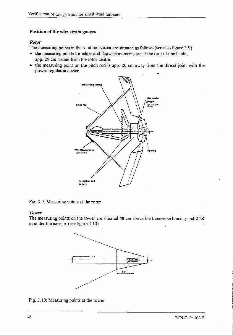
Position of the wire strain gauges
RotorThe measuring points in the rotating system are situated as follows (see also figure 3.9)
the measuring points for edge- and flapwise moments are at the root of one blade,app. 29 cm distant from the rotor centre.
¯ the measuring point on the pitch rod is app. 20 cm away from the thread joint with thepower regulaton device.
Fig. 3.9: Measuring points at the rotor
TowerThe measuring points on the tower are situated 48 cm above the transverse bracing and 2.28m under the nacelle. (see figure 3.10)
Fig. 3.10: Measuring points at the tower
46 ECN-C--96-033 B

Appendix 4
4. Analysis methods
4.1 Analysis method for power performance testing
The determination of power curve and rotor speed characteristic was carried out according tointernational standards as defined in the IEA-recommendation "Recommended Practices forWind Turbine Testing and Evaluation; 1. Power Performance Testing; 2.Edition 1990".
4.2 Analysis method for load measurement
Specifications for the execution of the load measurements for the INVENTUS 6,deviating from the IEC-TC 88 outline
¯ for the measurements within load case A a measurement matrix was developed. The windspeed classes were divided into 2.5 m/s hint and tho tl,rh,,lono,~ ;nto~;tx ol ..... l..÷.-, oz
bins. So a maximum of 40 time series can be recorded in the demanded class I, II, III andIV instead of only 10 time series. During the evaluation attention has to be drawn to thefact that not all the used measuring values for the average value are measured in just onerow of 10 minutes. Furthermore the measured time series should be equally divided overthe whole wind speed range of 5 m/s. These demands can easilier be reached with themore detailed matrix. Fig. 4.1 shows an example of the matrix for one measuring period.
Meas urement-Matdx 18.11 .-22.11.95wind speed rmls]
2.5-50 ~ 50-7.5 75- 100 150- 175 22.5-2500-5% 1~ o
1¢ 1~ 010-15~1~
>2o% 1~
1~
Fig. 4.1: Measurement matrix
During the whole measurement period from 16.11.1995 to 21.02.1996 seven matriceswere recorded by reading the data from the harddisk and reseting the matrix. Because ofproblems with the telemetry signals only some of the measured time series were usable.
Furthermore a file "liste.dat" is created during normal operation, containing informationabout filename of the 1-minute time series, average wind speed, turbulence intensity,average power and maximum yaw speed:
ECN-C--96-033 B 47
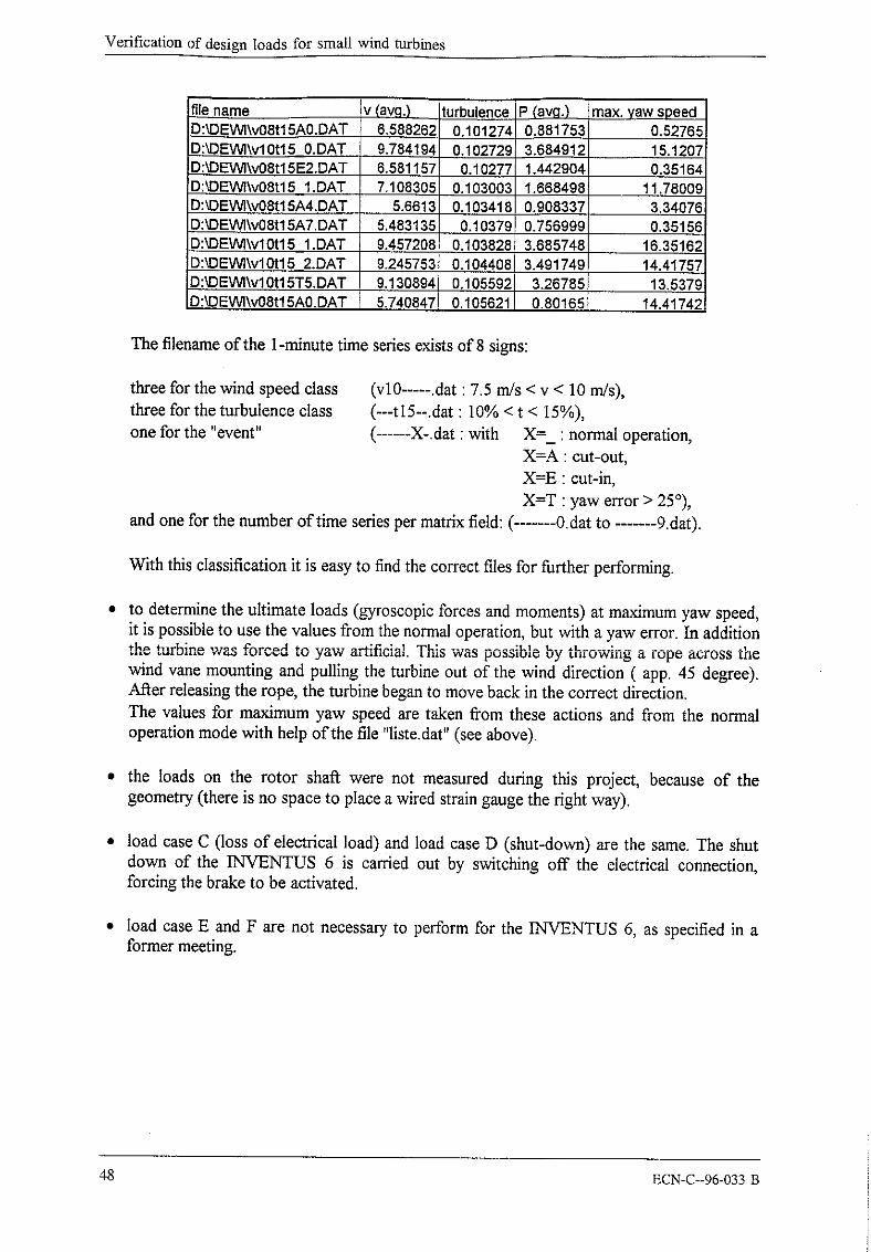
Verification of design loads for small wind turbines
_file name v (avg) turbulence P (av.q.) max. yaw speed):~DEWI\v08tl 5A0.DAT 6.588262 0.101274 0.881753 0.52765D:~DEWl\v10t15 0.DAT 9.78419, 0.102729 3.684912 15.1207DflDEWI\v08t15E2.DAT 6.581157 0.10277 1.442904 0.35164D:kDEWI\v08t15 1.DAT 7.108305 0.103003 1.668498 11.78009D:~OEWI\v08tl 5A4.DAT 5.6613 0.103418 0.908337 3.34076D:~)EWI\v08t15A7.DAT 5.483135 0.10379 0.7569991 0.3515~DflDEW]\v10t15 1.DAT 9.457208 0.103828 3.685748 16.35162DflDEWI~vl 0tl 5 .,2.DAT 9.245753 0.104408 3.491749 14.41757DflDEWI\vl 0tl 5T5.DAT 9.130894 0.105592 3.26785 13.5379DflDEW]\v08tl 5A0,DAT 5.740847 0.105621 0.80165 14.41742
The filename of the 1-minute time series exists of 8 signs:
three for the wind speed classthree for the turbulence classone for the "event"
(vl0 ..... .dat : 7.5 m/s < v < 10 m/s),(---tl5--.dat : 10% < t < 15%),
X-.dat : with X=_ : normal operation,X=A : cut-out,X=E : cut-in,X=T : yaw error > 250),
and one for the number of time series per matrix field: ( .......0.dat to .......9.dat).
With this classification it is easy to find the correct files for further performing.
¯ to determine the ultimate loads (gyroscopic forces and moments) at maximum yaw speed,it is possible to use the values from the normal operation, but with a yaw error. In additionthe turbine was forced to yaw artificial. This was possible by throwing a rope across thewind vane mounting and pulling the turbine out of the wind direction ( app. 45 degree).After releasing the rope, the turbine began to move back in the correct direction.The values for maximum yaw speed are taken from these actions and from the normaloperation mode with help of the file "liste.dat" (see above).
¯ the loads on the rotor shaft were not measured during this project, because of thegeometry (there is no space to place a wired strain gauge the right way).
¯ load case C (loss of electrical load) and load case D (shut-down) are the same. The shutdown of the INVENTUS 6 is carried out by switching off the electrical connection,forcing the brake to be activated.
¯ load case E and F are not necessary to perform for the INVENTUS 6, as specified in aformer meeting.
48 ECN-C--96-033 B
Appendix 4
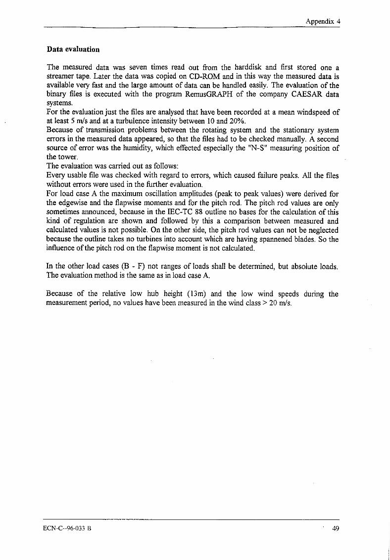
Data evaluation
The measured data was seven times read out from the harddisk and first stored one astreamer tape. Later the data was copied on CD-ROM and in this way the measured data isavailable very fast and the large amount of data can be handled easily. The evaluation of thebinary files is executed with the program RemusGRAPH of the company CAESAR datasystems.For the evaluation just the files are analysed that have been recorded at a mean windspeed ofat least 5 m/s and at a turbulence intensity between 10 and 20%.Because of transmission problems between the rotating system and the stationary systemerrors in the measured data appeared, so that the files had to be checked manually. A secondsource of error was the humidity, which effected especially the "N-S" measuring position ofthe tower.The evaluation was carried out as follows:Every usable file was checked with regard to errors, which caused failure peaks. All the fileswithout errors were used in the further evaluation.For load case A the maximum oscillation amplitudes (peak to peak values) were derived forthe edgewise and the fiapwise moments and for the pitch rod. The pitch rod values are onlysometimes announced, because in the IEC-TC 88 outline no bases for the calculation of thiskind of regulation are shown and followed by this a comparison between measured andcalculated values is not possible. On the other side, the pitch rod values can not be neglectedbecause the outline takes no turbines into account which are having spannened blades. So theinfluence of the pitch rod on the flapwise moment is not calculated.
In the other load cases 03 - F) not ranges of loads shall be determined, but absolute loads.The evaluation method is the same as in load case A.
Because of the relative low hub height (13m) and the low wind speeds during themeasurement period, no values have been measured in the wind class > 20 m/s.
ECN-C--96-033 B 49
Verification of design loads for small wind turbines
5. Measurement results
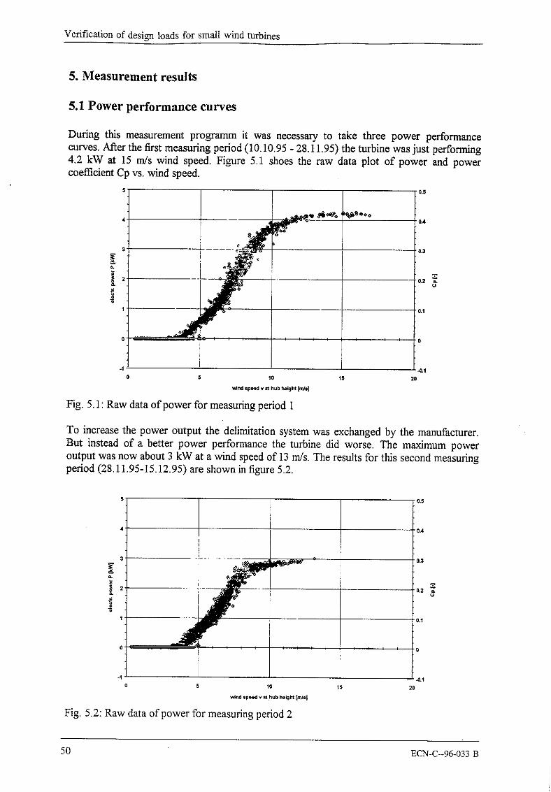
5.1 Power performance curves
During this measurement programm it was necessau¢ to take three power performancecurves. After the first measuring period (10.10.95 - 28.11.95) the turbine was just performing4.2 kW at 15 m/s wind speed. Figure 5.1 shoes the raw data plot of power and powercoefficient Cp vs. wind speed.
0
0.5
0,4
0.3
Fig. 5.1: Raw data of power for measuring period I
To increase the power output the delimitation system was exchanged by the manufacturer.But instead of a better power performance the turbine did worse. The maximum poweroutput was now about 3 kW at a wind speed of 13 m/s. The results for this second measuringperiod (28.11.95-15.12.95) are shown in figure 5.2.
o
0 0
20
Fig. 5.2: Raw data of power for measuring period 2
0.5
0,4
0.$
50 ECN-C--96-033 B
Appendix 4
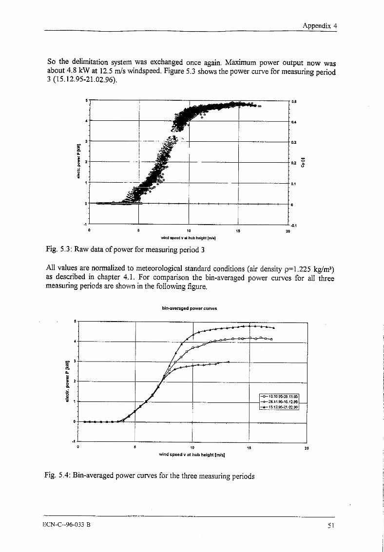
So the delimitation system was exchanged once again. Maximum power output now wasabout 4.8 kW at 12.5 m/s windspeed. Figure 5.3 shows the power curve for measuring period3 (15.12.95-21.02.96).
Fig. 5.3: Raw data of power for measuring period 3
0.5
0.3
All values are normalized to meteorological standard conditions (air density 0=1.225 kg/m3)as described in chapter 4.1. For comparison the bin-averaged power curves for all threemeasuring periods are shown in the following figure.
wind speed v at hub height [mJs]2O
Fig. 5.4: Bin-averaged power curves for the three measuring periods
51

Verification of design loads for small wind turbines
The rotational speed characteristics of the INVENTUS 6 with its two power stages areindependent of the delimitation system, therefore only one plot of rotational speed as afunction of wind speed is shown in the following diagramm.
140
120 ’
100’
[ I I I IIII
10 15 20
wind speed v at hub height [m/s]
Fig. 5.5: Raw data of rotational speed
5.2 Measurement results for load measurement
Results load case A
Loads on the blade root, normal operationwind speed loads number of average range range with calculated
class values value (2 ± 2 ~ valuem/s N/Nm N/Nm N/Nm N/Nm
5- 1088 355 98 257-453
159 102 57-26110 - 15
44 441 97 344-538277 135 142 - 412
15- 209 438 78 359-516
288 97 191-386> 20 AF~ = 4252
AM~ 0 AM~ = 349AMvB AM~ = 446
Tab. 5.1: Results for load case A; loads on the blade root
52 ECN-C--96-033 B
Appendix 4
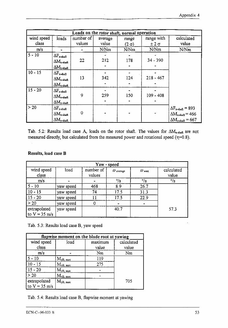
Loads on the rotor shaft, normal o~ ~erationwind speed loads number of average range range with calculated
class values value (2 +2~ valuem/s N/Nm N/Nm N/Nm N/Nm
5- 1022 212 178 34 - 390
z~Vly~a10- 15 AFx-shaft
13 342 124 218-467
15 - 20 !~Fx.shafl.9 259 150 109-408
AMy.~h.ft> 20 !~Fx.shaR AFx~a = 893
0 AMx.~a= 466AIVly~h.a = 667
Tab. 5.2: Results load case A, loads on the rotor shaft. The values for AM~.~e are notmeasured directly, but calculated from the measured power and rotational speed (rl=0.8).
Results, load case B
Yaw - speedwind speed !oad number of calculated
class values valuerrl]s % °/s O/s
5- 10 yaw speed 468 8.9 26.710- 15 yaw speed 74 17.5 31.315- 20 yaw speed 11 17.5 22.9> 20 yaw speed 0extrapolated yaw speed 40.7 57.3to V = 35 m/s
Tab. 5.3: Results load case B, yaw speed
flapwise moment on the blade root at yawingwind speed load maximum calculated
class value valuemrs Nm Nm
5- 10 11910- 15 27515 -20> 20extrapolated 7O5to V = 35 m/s
Tab. 5.4: Results load case B, flapwise moment at yawing
ECN-C--96-033 B 53

Verification of design loads for small wind turbines
Results, load case D
Shut down, edgewise moment on the blade rootwind speed load calculated
class value valuem/s Nm Nm
5-+1 My.B, ranx 43110±1
Mx.B, max 47715-+l
20~
extrapolated 687to V = 35 m/s
5.3. Extrapolation of load measurements
Load Case A:
Edgewise bending moment on the blade root, range AM~
Figure 5.6 shows the single values of the edgewise moment ranges vs. wind speed. Anextrapolation according to: AM~ = -2.11 * vz + 56.73 * v + 66.67 (coefficient of correlation:r = 0.79856) gives a maximum edgewise moment range of AM~,m,x = 448 Nm at v = 13.4m/s. The maximum single value is AM~,~,x = 533 Nm.
Extrapolation ofedgewise bending moment
5 10 15 20
wind speed v ;~t ht/b height
Fig. 5.6: Extrapolation of edgewise moment on the blade root
54 ECN-C--96-033 B

Appendix 4
Flapwise bending moment on the blade root, range &M~
Figure 5.7 shows the single values of the flapwise moment ranges vs. wind speed. Anextrapolation according to: AMrB = -1.75 * v2 + 55.55 * v - 138.44 (coefficient ofcorrelation: r = 0.81737) gives a maximum edgewise moment range Of zM’VIyB,max = 302 Nm atv = 15.9 m/s. The maximum single value is AMy~,,~ = 451 Nm.
t0
wind speed V at hub height [m/s]
Fig. 5.7: Extrapolation of flapwise moment on the blade root
Torsional moment on the rotor shaft, range
The torsional moment on the rotor shaft was not measured directly, but calculated from themeasured electrical power and rotational speed (efficiency = 0.8). Figure 5.8 shows the singlevalues of the torsional moment ranges vs. wind speed. An extrapolation according to:~a = -6.02 * vz + 135.10 * v - 398.17 (coefficient of correlation: r = 0.78778) gives amaximum torsional moment range of AMx-shao,~x = 360 Nm at v = 11.2 m/s. The maximumsingle value is AMx.~a = 459 Nm.
wind speed v at hub height
Fig. 5.8: Extrapolation of torsional moment on the rotor shaR
55

Verification of desi~a loads for small wind turbines
Load case B:
Extrapolation of yaw speed
Figure 5.9 shows the single values of the yaw speed ~o versus the wind speed v. Anextrapolation according to: 0~ = 19.50 * In(v) - 28.59 (coefficient of correlation: r = 0.73014)gives a yaw speed of~0 = 40.7 °/see at v = 35.0 rrds. The maximum single value is ~ = 31.3°/see.
25
Extrapolation ofyaw speed
y = 19.50Ln(x) - 28.59R~ = 0.53
w!nd spsed v at hub he!ght [rids]
Fig. 5.9: Extrapolation of yaw speed
56 ECN-C--96-033 B

Appendix 4
6. Comparison
parameter
Prat~l
measuredvalue4.81283.35448
calculatedvalue
5.0128
3.83466
Load case A: NORMAL OPERATION2dVIm 448AMvB 302
zklVlx~h,~ 360Load case B: YAWING
(om~ 40.7 57.3(275) 705
Load case D: SHUT DOWNM~B,,.~x (477) 687
349446466
dim
kWrpm
Nm
Nm
°/seeNm
Nm
measured /calculated
0.961.0
0.870.96
1.280.680.77
0.71(0.39)
0.69)
ECN-C--96-033 13 57
Verification of design loads for small wind turbines
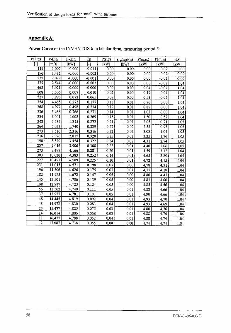
Appendix A:
Power Curve of the INVENTUS 6 in tabular form, measuring period 3:
values v-Bin P-Bin Cp P(si~) sig/sqrt(n) P(max) P(min)[-1 [m!s] [-]
119 1.007 -0.000 -0.011 0.00 0.00 0.00 -.0.02 0.00196 1.482 -0.000 -0.002 0.00 0.00 0.00 -0.02 0.00232 2.029 -0.000 -0.001 0.00 0.00 0.00 -0.02 0.00379 2.544 -0.000 -0,002 0.00 0.00 0.06 -0.02 1.04462 3.021 -0,000 -0.000 0.00 0,00 0.04 -0.02 1.04608 3.506 0.007 0.010 0,02 0.00 0.19 -0.04 1.04527 3.996 0.072 0.065 0.09 0.00 0.53 -0.05 1.04354 4.465 O,273 0.177 0.18 0,01 0.76 0.00 1.04268 4.972 0.498 0.234 0.19 0.01 0.87 0.00 1.04236 5.466 0.766 0,271 0.!4 0.0!~ 1.03 0.00 1.04234 6.001 1.008 0.269 0.15 0.01 1.50 0.57 1.04242 6,535 1.315 0.272 0.21 0.01 i 2.05 0.71 1.05264 7.033 1.740 0.289 0.27 0.02 2,53 0.93 1.05273 7.510 2,316 0.316 0,32 0.02 3.08 1.04 1.05216 7.976 2.815 0.320 0.25 0.02 3.25 1.76 1.05190 8.520 3,454 0.322 0.34 0.02 4.31 2.74 1.05237 9.016 3.906 0.308 0.22 0.01 4.40 3.06 1.05273 9.498 4.166 0.281 0.20 0.01 4.59 3.12 1.04303 10.020 4.383 0.252 0.14 0.01 4,65 3.80 1.04227 10.493 4.509 0.225 0.10 0.01 4,72 4.15 1.04231 11.015 4.571 0.198 0.07 0.00 4.78 4.31 1.04196 11.506 4.626 0.175 0.07 0.01 4.75 4.18 1.04182 11.985 4.672 0.157 0.05 0.00 4.80 4.47 1.04145 12.501 4.706 0.139 0.05 0,00 4.81 4.60 1.04108 12.997 4.723 0.124 0,05 0.00 4.85 4.56 1.0456 13.502 4.749 0.111 0.05 0,01 4.82 4.66 1.0437 13.977 4.781 0.101 0.05 0.01 4.90 4.66 1.0448 14.445 4.819 0.092 0.04 0.01 4.93 4.70 1.0443 14.972 4.830 0.083 0.04 0.01 4.93 4.69 1.0423 15.477 4.825 0.075 0.03 0.01 4.88 4.76 1.0414 16.014 4.806 0.068 0.03 0.01 4,88 4.74 1,0411 16.477 4.788 0.062 0,04 0.01 4,88 4.74 1.04
17.087 4.738 0.055 0.00 0.00 4.74 4.74 1.04
58 ECN-C--96-033 B

5. Measurements LMW 1003 (CRES)
LMW1003 FLAP BENDING MOMENT
00 3 4 6 8 10 12 14 16 18 20
LMW100~ FLAP BENDING MOMENTSDV
oo 4 12 16 20 24
ECN-C--96-033 B 59

Verification of design loads for small wind turbines
LMW 1003 TOWER BENDING MOMENT
00 4
LMW 1003 TOWER BENDING MOMENT
8O00
00 16
60 ECN-C--96-033 B
Appendix 5
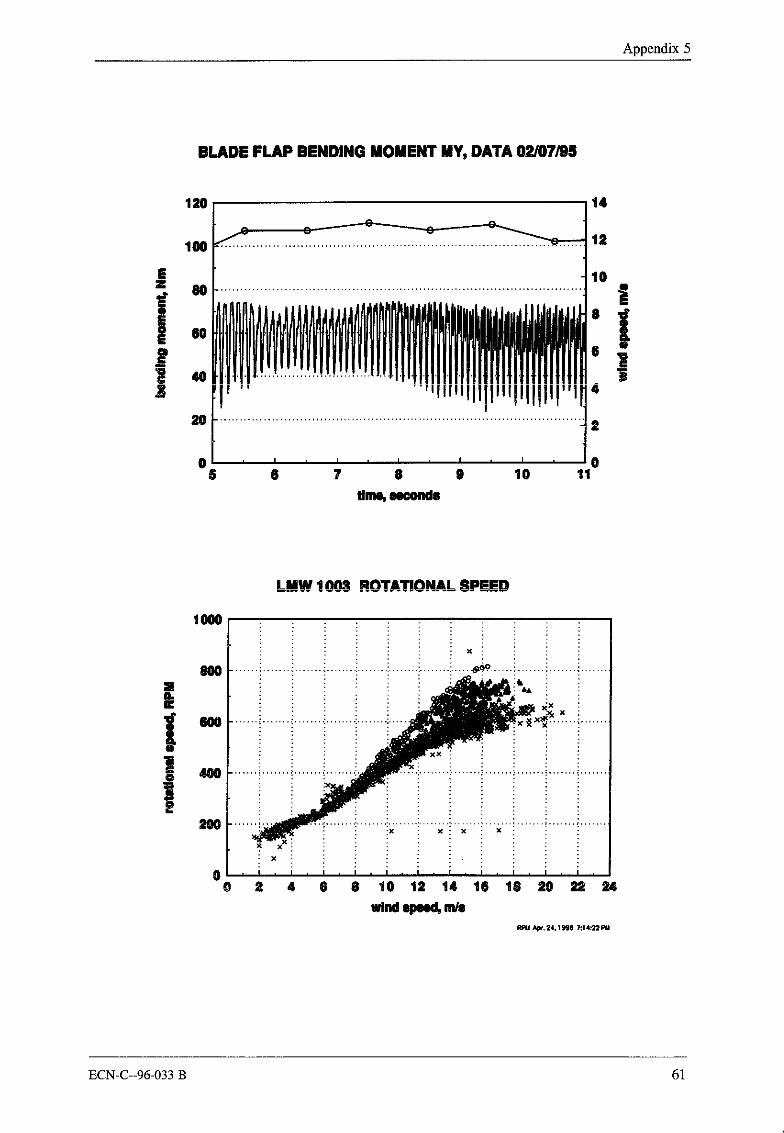
BLADE FLAP BENDING MOMENT MY, DATA 02/07/95
14
12
~/ , I , I , I , I , I , /05 6 ? 8 9 10 11
1000
80O
LMW !00~ ROTATIONAL SPEED
00 2 4 6 8 10 11 14 16 18 20 2~ 24
wind epeed, m/s
ECN-C--96-033 B 61

Verification of design loads for small wind turbines
TIME SERIES SAMPLING RATE 1 60 Hz15
I0
100
8OE 60z 40
20
6ooot5000
E4000z3000
20001000
2
yaw position
3 4 5
tower bending moment
3 4 5time, sec
6
6
62 ECN-C--96-033 B

6. Measurements Proven WT 2200 (NEL)
ECN-C--96-033 B 63

Verification of design loads for small wind turbines
LD05N531
LD05n531 .DATAn average hub-height wind speed of 5 m/s was obtained for the duration of the 64-second measurement. The peak windspeed was 6.5 m/s.]’he load has not cut-in at this wind speed.]’he zebadee transducer (flap/pitch) is broken at this point and should be ignored.
]-he flap transducer is OK.
]-he yaw transducer is not perfectly aligned with the wind direction although the turbine did operate with a slight visual yaw9rror.
The tower excitation after 30-seconds seems to occur because the wind direction changes, but the wind speed is too lowto overcome the friction in the yaw system, seems to be due to a significant change in yaw position.
76.5
g4
3.50 10 20 30 40 50 60
Time (Seconds)
-- Wind_Speed
-- RPM
10 20 30 40 50 60Time (Seconds)
2.52
1.51
0.500 10 20 30 40 50 60
Time (Seconds)
Power
10 20 30 40 50 60Time,Seconds|
Zebadee
Page I
64 ECN-C--96-033 B

Appendix 6
LDO5N531
10 20 30 40Time (Seconds)
50 60
Flap
Torque
10 20 30 40Time (Seconds)
50 60
10 20 30 40Time (Seconds)
50 60
......................YawDireotion
Tower Base Bending-- NS
10 20 30 40Time (_Seconds)
50 60
0 10 20 30 40Time (Seconds)
5O 60
Tower Base Bending-- EW
ECN-C--96-033 B 65

Verification of design loads for small wind turbines
LD10N594
LD10n594.DATAn average hub-height wind speed of 10 m/s was obtained for the duration of the 64-second measurement. The peakwind speed was 11.7 m/s.
The zebadee transducer (flap/pitch) is broken at this point and should be ignored.
The flap transducer is OK.
The yaw transducer is not perfectly aligned with the wind direction although the turbine did operate with a slight visualaw error.
315310
~305300295290285
0
2.52
0
200150
~ 10050
.~ 0-50
~-100-150-200
0
10 20 30 40 50 60Time (Seconds)
10 20 30 40 50Time (_Seconds)
10 20 30 40 50Time (Seconds)
10 20 30 40 50 60Time (Seconds)_
60
60
-- Wind_Speed
-- RPM
Power
Zebadee
Page 1
66 ECN-C--96-033 B

Appendix 6
LD10N594
173172
~171
168167166165
u
-- Flap
10 40Time (Seconds)
50 60
Torque
10 20 30 40Time(Seconds)
50 60
0
654
10 20 30 40Time (Seconds)
50 60
YawDirection
Tower Base Bending-- NS
10 40Time (Seconds)
50 60
Tower BaSeEW Bending
10 20 30 40Time(Seconds)
50 60
Page 2
ECN-C--96-033 B 67

Verification of design loads for small wind turbines
LD15N832
LD15n832.DATAn average hub-height wind speed of 15 m/s was obtained for the duration of the 64-second measurement. The peakwind speed was 19.1 m/s.Note that the RPM and power reduce as the wind speed increases between 20 and 40 seconds.
]-he zebadee transducer (flap/pitch) is broken at this point and should be ignored.
The flap transducer is OK,
]’he yaw transducer is not perfectly aligned with the wind direction although the turbine did operate with a slight visual yaw~rror.
10 20 30 40 50 60Time (Seconds)
-- Wind_Speed
RPM
0 10 20 30 40 50 60Time (Seconds)
2.52
1.51 Power
0.50
0 10 20 30 40 50 60Time (Seconds)
1501005o0
~ -5o~-100
-150-200
0 10 20 30 40 50 60Time ~_Seconds|
Zebedee
Page 1
68 ECN-C--96-033 B

Appendix 6
LD15N832
10 2O 30 40Time (Seconds)
5O 6O
Flap
858075
605550
-- Torque
0 10 20 30 40Time (Seconds)
50 60
100
i90807060
3OI0 20 30 40
Time(seconds)_6O
YawDirection
Tower Base Bending-- NS
10
10
20
2O
30 40Time (SecondsJ
30 40Time (Seconds)
5O
5O
6O
6O
Tower Base Bending-- EW
Page 2
ECN-C--96-033 B 69
Verification of design loads for small wind turbines
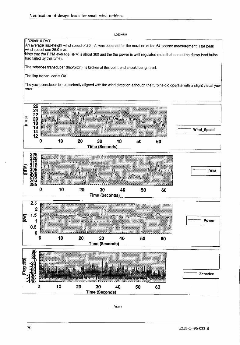
LD20N910
LD20n91 O.DATAn average hub-height wind speed of 20 m/s was obtained for the duration of the 64-second measurement. The peaka4nd speed was 25.0 m/s.Note that the RPM average RPM is about 300 and the the power is well regulated (note that one of the dump load bulbshad failed by this time).
The zebadee transducer (flap/pitch) is broken at this point and should be ignored.
The flap transducer is OK.
The yaw transducer is not perfectly aligned with the wind direction although the turbine did operate with a slight visual yawerror.
2624222018161412
0
325320315310305300295290285
2.52
10 20 30 40 50 60T~
10 20 30 40 50Time(Seconds)
10 20 30 40 50Time(Seconds)
60
6O
Wind_Speed
-- RPM
Power
50Time(Seconds)
6O
Zebadee
70 ECN-C--96-033 B

Appendix 6
LD20N910
10 20 30 40 50 60Time (Seconds)
10 20 30 40 50 60Time (Seconds)
-- Flap
120110100
80
605O
10 20 30,~u"^ 50 60
Torque
Time (Seconds)
YawDirection
0 10 20 30 40 50 60Time (Seconds}_
Tower Base Bending-- NS
Tower Base Bending-- EW
10 20 30 40 50 60Time (Seconds)
Page 2
ECN-C--96-033 B 71

Verification of design loads for small wind turbines
LD25N871
LD25n871 .DATThis 64-second data file represents the highest wind speeds recorded during the measurement campaign with anaverage hub-height wind speed of 25 m/s for the duration of the 64-second measurement. The peak wind speed was34.3 m/s.Note that the RPM remains in the range 290-335 rpm and that the power is well regulated (note that one of the dump loadbulbs had failed by this time).
The zebadee transducer (flap/pitch) is broken at this point and should be ignored.The flap transducer is OK.]-he yaw transducer is not perfectly aligned with the wind direction although the turbine did operate with a slight visualyaw error.The peak tower loads (NS and EW directions) are considerably higher than those obtained from consideration of themean trends.
Wind_Speed
0 10 20 30 40 50 60Time [Seconds)
-- RPM
0 10 20 30 40 50 60Time (Seconds)
2.52
1.51
0.50
Power
0 10 20 30 40 50 60Time,Seconds)_
200150lOO5O
~ o~ -50
-100-150
0 10 20 30 40 50 60Time(Seconds~
Zebadee
Page !
72 ECN-C--96-033 B

Appendix 6
LD25N871
20019519o185180175170165
10 20 30 40Time (Seconds)
0 10 20 30 40 50Time (Seconds)
i160150140130120
~_~11010090
0
Flap
-5-10-15
~-20-25-30-35-40-45
0
5O 6O
50
o5-10-15
-30-35
6O
!0 20 30 40 50Time (Seconds)
Torque
-° -’°--~ Yaw..... Direction
lTower Base BendingNS
10 20 30 40 50Time (Seconds)
6O
Tower Base Bending-- EW
10 20 30 40 50Time (Seconds)
6O
Page 2
ECN-C--96-033 B 73

Verification of design loads for small wind turbines
(.6ep) ell~U,~ del-./
74 ECN-C--96-033 B

Appendix 6
rn
, !
(tUN) ].uetuolR i~u!pue~]
C3
ECN-C--96-033 B 75

Verification of design loads for small wind turbines
76 ECN-C--96-033 B

7. Comparison Danish method / IEC code (Riso)
Characteristic material values assumed in the calculations:
Blades:Wood/Glass fibre ultimate strengthWood/Glass fibre fatigue strengthYoungs modulus for glass fibre
Main shaft:Steel C45 DIN 17200
Steel st37-2 DIN 17100Material without welding
Fillet welding at bottom flange
Rm=40MPaJ200MPaOfat--24MPaJ60MPa (DK)E--20000MPa
Rm=650MPaafat=+195MPa including reduction for 97.5% survival,surface and volume (DK)
Rm=360MPaEuro code 3. detail class 140 corresponding to 104MPa at5"106 (constant amplitude fatigue limit) (DK)
Euro code 3. detail class 71 corresponding to 52MPa at5"106 (constant amplitude fatigue limit) (DK)
Basic assumptions for calculation input:
LMW 1003 INVENTUS 5kW
nrated--700rpmPrated=0-7kWVrated=15.0 m/secClmax=0.4Aswept=7.69 m2
nrated= 124rpmPrated=5.0kWVrated=10.5 m/secClmax=l.2Aswept=28.27 m2
Since the LMW 1003 runs with nearly constant tip speed ratio ~,2/3--5.1 the lift coefficient willbecome rather low. The Inventus machine is pitch regulated but at the moment it is not quite clearhow the pitch angle varies as wind speed, consequently the C! is stipulated to the best of onesjudgement.
It is obvious that the DK rules and the IEC rules are based on quite different philosophy. Calcula-tions with the DK rules cause rather high characteristic loads, taking in account the high de~:ee ofuncertainty in site and operational conditions as well as tack of knowledge on loads and behaviourof this very different turbines. Besides it was a request to use the same safety factors as in DS 472which correspond to the values given in the codes for the relevant materials.The IEC rules seem to cause rather low characteristic loads, on the other hand the safety factors arehigh.
For convenience the material design values in the two codes are compared below.
ECN-C--96-033 B 77
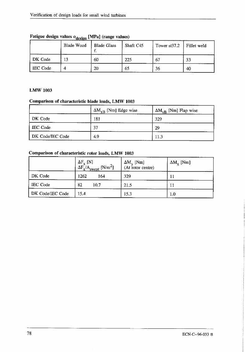
Verification of design loads for small wind turbines
atlgue design values Odesign [MPa] (range values)
Blade Wood Blade Glass Shaft C45 Tower st37.2 Fillet weldf.
DK Code 13 60 225 67 33
IEC Code 4 20 65 36
LMWIO03
Comparison of characteristic blade loads, LMW 1003
AMxB [Nm] Edge wise AMyB [Nm] Flap wise
DK Code 1~1±~ 329
IEC Code 37 29
DK Code/IEC Code 4.9 11.3
Comparison of characteristic rotor loads, LMW 1003
AFx [N] AMx [Nm]AFx/Aswept [N/m2]
AMy [Nm](At rotor centre)
DKCode 1262 164 329 11
IEC Code 82 10.7 21.5 i1
DK Code/IEC Code 15.4 15.3 1.0
78 ECN-C--96-033 B
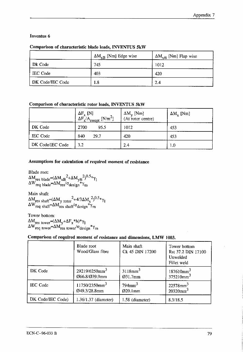
Appendix 7
Inventus 6
Comparison of characteristic blade loads, INVENTUS 5kW
AMxB [Nm] Edge wise AMyB [Nm] Flap wise
Dk Code 745 1012
IEC Code 403 420
DK Code/IEC Code 1.8 2.4
Comparison of characteristic rotor loads, INVENTUS 5kW
AFx [N] AMx [Nm]AFx/Aswept [N/m2]
AMy [Nm]
DK Code 2700 95.5 1012 453
!EC Code 840 29.7 420 453
DK Code/IEC Code 3.2 2.4 1.0
Assumptions for calculation of required moment of resistance
Blade root:
AMres blade=(AMxB2+AMyB2)0"5 *y1AWreq blade=A Mres/~design *Ym
Main shaft:2 2 0.5,
AMres shaft=(AMy rotor +4!3AMx )AWreq shaft--AMres shaft/°design*Ym
Tower bottom:
AMres tow r=(AM +AF *h)*y,e y xAWreq tower=AMres tower/Odesi~a*Ym
Comparison of required moment of resistance and dimensions, LMW 1003.
Blade root Main shaft Tower bottomWood!Glass fibre Ck 45 DIN 17200 Rst 37.2 DIN 17100
UnweldedFillet weld
DK Code 29219/6250mm3 3118mm3 i87610mm3066.8/039.9mm O31.7mm 375210mm3
IEC Code 11750/2350mm3 794mm3 22578mm3O49.3/28.8mm 020.1 mm 20320mm3
DK Code/IEC Code) 1.36/1.37 (diameter) 1.58 (diameter) 8.3/18.5
ECN-C--96-033 B 79
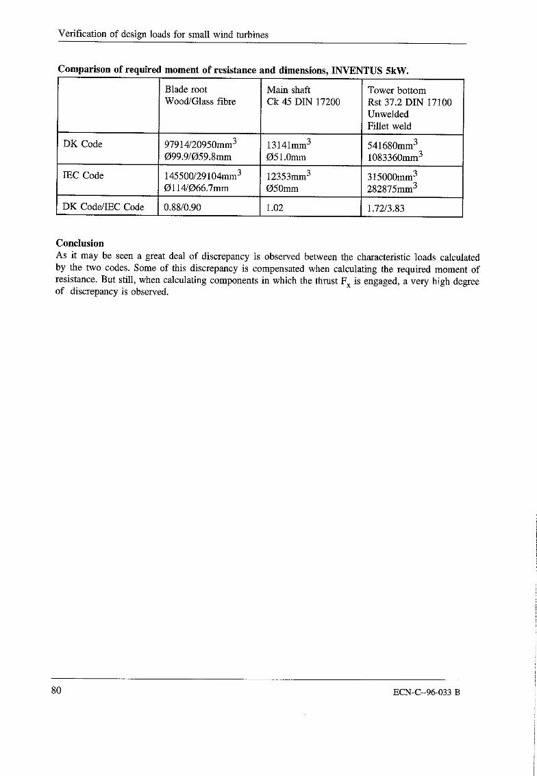
Verification of design loads for small wind turbines
0 * oC mpanson of reqmred moment of resistance and dimensions, INVENTUS 5kW.
Blade root Main shaft Tower bottomWood/Glass fibre Ck 45 DIN 17200 Rst 37.2 DIN 17100
UnweldedFillet weld
DK Code 97914/20950mm3 13141mm3 541680mm3O99.9/O59.8mm 051.0mm 1083360mm3
IEC Code 145500/29104mm3 12353mm3 315000mm30114/066.7mm O50mm 282875mm3
DK Code/IEC Code 0.88/0.90 i .02 1.72/3.83
ConclusionAs it may be seen a great deal of discrepancy is observed between the characteristic loads calculatedby the two codes. Some of this discrepancy is compensated when calculating the required moment ofresistance. But still, when calculating components in which the thrust Fx is engaged, a very high de~eeof discrepancy is observed.
80 ECN-C--96-033 B