ventus - otto bock - produktdokument | rullstolar ... all safety information and instructions in...
TRANSCRIPT

VentusInstructions for use (user) ...................................................................................... 3

2 | Ottobock Ventus

Foreword 1 5.............................................................................................................................................................Product Description2 5............................................................................................................................................Function 2.1 5.............................................................................................................................................Product Overview2.2 6.................................................................................................................................
Safety3 7....................................................................................................................................................................Explanation of Warning Symbols3.1 7.............................................................................................................General safety instructions3.2 7.....................................................................................................................Safety Instructions for Use3.3 7.....................................................................................................................Further information3.4 11..............................................................................................................................Name plate and warning labels3.5 11.............................................................................................................Name plate3.5.1 11.........................................................................................................................................Warning labels3.5.2 11...................................................................................................................................
Delivery4 12...............................................................................................................................................................Scope of Delivery4.1 12................................................................................................................................Standard equipment4.2 12............................................................................................................................Options4.3 12.............................................................................................................................................Storage4.4 12..............................................................................................................................................
Preparation for Use5 12..........................................................................................................................................Assembly5.1 12...........................................................................................................................................
Usage6 14..................................................................................................................................................................Techniques for Using a Wheelchair6.1 14.......................................................................................................Getting into the wheelchair/transfers6.2 14.....................................................................................................Information on use6.3 15..............................................................................................................................Footrests6.3.1 15...........................................................................................................................................Adjusting the footrest (footplate)6.3.1.1 15...........................................................................................................Fastening / removing the calf strap6.3.1.2 15........................................................................................................Seat cushion / backrest upholstery6.3.2 16........................................................................................................Fastening / removing the seat cushion6.3.2.1 16...................................................................................................Fastening / removing the backrest pad6.3.2.2 17..................................................................................................Side panels6.3.3 18........................................................................................................................................Adjusting the armrest height6.3.3.1 18.................................................................................................................Folding down the side panels6.3.3.2 18...............................................................................................................Removing the "Padded" armrest6.3.3.3 19...........................................................................................................Adjusting a Channel Forearm Pad with Swivel Unit6.3.3.4 20.................................................................................Push handles6.3.4 20......................................................................................................................................Adjusting the push handles6.3.4.1 20..................................................................................................................Rear wheels6.3.5 21.......................................................................................................................................Removing / fitting the rear wheels6.3.5.1 21.........................................................................................................Castors / castor forks6.3.6 22..........................................................................................................................Brakes6.3.7 22...............................................................................................................................................Using the knee lever wheel lock6.3.7.1 23............................................................................................................Anti-tipper / tip-assist6.3.8 23...........................................................................................................................Activating / deactivating the anti-tipper6.3.8.1 24...................................................................................................Using the tip-assist6.3.8.2 25..............................................................................................................................Wheelbase extension6.3.9 25...........................................................................................................................Shock absorber system6.3.10 26.......................................................................................................................Headrests and neckrests6.3.11 27.....................................................................................................................Additional options6.3.12 27...............................................................................................................................Disassembly / Transport6.4 27......................................................................................................................Use in a wheelchair accessible vehicle6.5 28..................................................................................................Care6.6 28..................................................................................................................................................Cleaning6.6.1 28............................................................................................................................................Disinfection6.6.2 28........................................................................................................................................
Table of contents
Ottobock | 3Ventus
Table of contents
Maintenance/Repair7 28.........................................................................................................................................Maintenance7.1 28.......................................................................................................................................Maintenance intervals7.1.1 29..........................................................................................................................Scopes of maintenance7.1.2 29........................................................................................................................Repair7.2 29...............................................................................................................................................Inner tube/rim tape/tyre replacement7.2.1 29.....................................................................................................
Disposal8 30.............................................................................................................................................................Disposal Information8.1 30............................................................................................................................
Legal Information9 31..............................................................................................................................................Service Life9.1 31........................................................................................................................................Liability9.2 31..............................................................................................................................................CE Conformity9.3 31....................................................................................................................................Warranty9.4 31............................................................................................................................................Trademarks9.5 31........................................................................................................................................
Technical Data10 31...................................................................................................................................................
4 | Ottobock Ventus
Table of contents

1 Foreword INFORMATION
Date of the last update: 2014-07-23► Please read this document carefully.► Follow the safety instructions.
INFORMATION► You can request this document as a PDF file from the Customer Care Center (CCC) at [email protected] or
from the manufacturer's service department (see inside back cover or back page for addresses).► It is possible to increase the display size of the PDF document.► For further questions about the instructions for use, please contact the authorised personnel who issued the
product to you.
You have purchased a high-quality product which can be put to versatile, daily use at home and outdoors. Please read these instructions for use before you start using the product. Familiarise yourself with the handling,functions and use of the product before using it. Observe all safety information and instructions in order to preventthe possibility of injury. Store these instructions for use in a safe place for future reference.Please note the following in particular:• All users (including children and youths) must be instructed in the use of the product by qualified personnel or
by an attendant using these instructions for use. • Attendants (persons who operate and push the product) must be instructed in the use of the product by quali
fied personnel using these instructions for use.• The product has been adapted to the needs of the user. Further changes may be made only by qualified per
sonnel. We recommend checking the product settings regularly in order to assure an optimum fit over the longterm. For growing children and youths in particular, fitting should be performed every six months.
• If you have any questions or cannot solve a problem, despite reading these instructions for use, please contactthe qualified personnel who fitted the product or the manufacturer's service department (please see insideback cover or back cover for addresses).
• The product may only be combined with the options listed here. The manufacturer assumes no liability for combinations with third-party medical devices and/or accessories not included in the modular system. Please alsoobserve the information in the section "Liability".
• Service and repairs to the product may only be carried out by qualified personnel. If you have any problems,please contact your specialist dealer. This ensures that any necessary repairs will be made exclusively withauthentic Ottobock spare parts.
• Your product may differ from the models shown. In particular, not all the options described in these instructions for use will be installed on your product.
• The manufacturer reserves the right to make technical changes to the model described in these instructions foruse.
2 Product Description2.1 Function The wheelchair is designed solely for individual use by persons who are unable to walk or who have a walkingimpediment, and can be operated either by the patient or by another person.The wheelchair can be used on solid ground both indoors and outdoors.
Ottobock | 5Ventus
Foreword
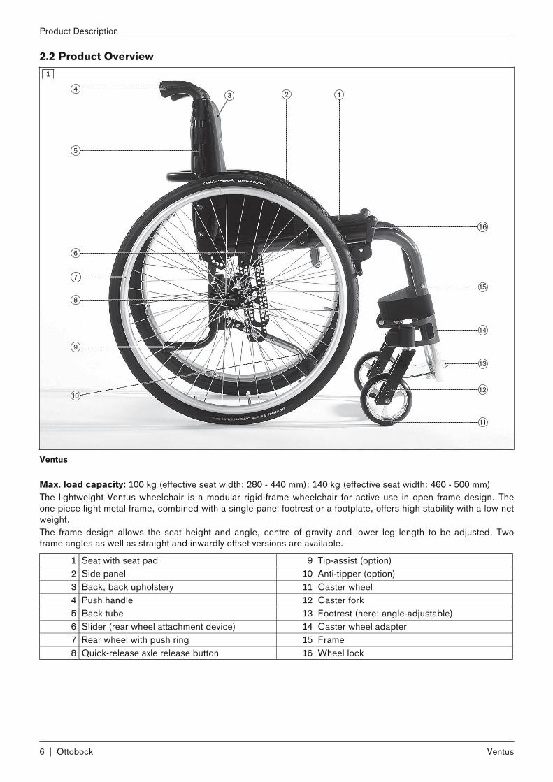
2.2 Product Overview1
Ventus
Max. load capacity: 100 kg (effective seat width: 280 - 440 mm); 140 kg (effective seat width: 460 - 500 mm)The lightweight Ventus wheelchair is a modular rigid-frame wheelchair for active use in open frame design. Theone-piece light metal frame, combined with a single-panel footrest or a footplate, offers high stability with a low netweight. The frame design allows the seat height and angle, centre of gravity and lower leg length to be adjusted. Twoframe angles as well as straight and inwardly offset versions are available.
1 Seat with seat pad 9 Tip-assist (option)2 Side panel 10 Anti-tipper (option)3 Back, back upholstery 11 Caster wheel4 Push handle 12 Caster fork5 Back tube 13 Footrest (here: angle-adjustable)6 Slider (rear wheel attachment device) 14 Caster wheel adapter7 Rear wheel with push ring 15 Frame8 Quick-release axle release button 16 Wheel lock
6 | Ottobock
Product Description
Ventus

3 Safety3.1 Explanation of Warning Symbols
WARNING Warnings regarding possible risks of severe accident or injury.CAUTION Warnings regarding possible risks of accident or injury.
NOTICE Warnings regarding possible technical damage.
3.2 General safety instructions
CAUTIONLack of familiarisation with instructions for useInjuries due to user error► Read the instructions for use before using the product. ► Familiarise yourself with the handling, functions and use of the product before using it. You can compromise
the safety of the user if you do not follow these instructions.
3.3 Safety Instructions for UseHazards during preparation for use
WARNINGIndependent modification of settingsRisk of tipping, falling or malposition► Do not modify the settings established by the qualified personnel. ► In case of problems with the settings (unsatisfactory seating position, caster wheel wobble etc.) please con
tact the qualified personnel who adjusted your product.
WARNINGSettings outside the safety limitsRisk of falling, tipping of the user► In certain versions and with certain settings, the wheelchair tends to tip backwards due to its design. The fea
ture is intentional in order to enable users with the corresponding physical preconditions to manoeuvrequickly and nimbly.
► Users with the necessary physical/psychological preconditions can be supplied with such versions/settings. Ifthe physical/psychological preconditions change, the wheelchair may no longer be used with these settings.In this case inform your dealer immediately.
WARNINGImproper handling of packaging materialsRisk of suffocation► Keep packaging materials away from children.
CAUTIONExposed pinch pointsRisk of crushing or pinching the fingers due to incorrect handling► When folding out the backrest, only grip by the specified components.
CAUTIONIncorrect fitting of the rear wheelsRisk of falling or tipping due to wheels coming loose► After every assembly, check the proper mounting of the rear wheels. The wheel axles must be securely locked
in the fitting.
Ottobock | 7Ventus
Safety
Hazards when getting in
CAUTIONIncorrect handling when getting inRisk of falling, tipping or rolling away due to incorrect handling► Activate the wheel lock each time before you get into or out of or transfer to or from the wheelchair.► Always get into the wheelchair from the side, where possible. ► Never step on the footrests/footplates when getting in and out.
CAUTIONIncorrect caster wheel positioningRisk of falling or tipping when leaning forward in the wheelchair► Prior to activities that require you to bend forward in the wheelchair (e.g. tying your shoes), maximise the sta
bility of the wheelchair. In order to do so, push the wheelchair backwards until the caster wheels turn forward.
Risk of hand injuries
CAUTIONPinching in exposed drive partsRisk of pinching and crushing of the hands► To avoid hand injuries, do not grasp between the rear wheel and the knee lever lock when driving your wheel
chair.► Do not reach between the spokes of the rear wheel.
CAUTIONPinching at componentsRisk of pinching and crushing of the hands► Pay attention not to pinch parts of your body at the wheel lock lever or between the side or frame parts.
CAUTIONHeat development when braking with push ringsRisk of burns to the hands► Wear leather gloves when travelling at high speeds.
Hazards while driving
CAUTIONTravelling without experienceRisk of falling, tipping of the user► Familiarise yourself with the wheelchair by practicing on level, easy terrain first.► Learn with the support of an assistant how the wheelchair reacts to changes in centre of gravity, e.g. down
ward or upward slopes, inclines or when overcoming obstacles.► Always activate the anti-tipper.
CAUTIONWrong centre of gravityRisk of tipping or rolling over► Do not lean too far out of the wheelchair when trying to pick up objects.► Lean well forward with your upper body when climbing gradients, overcoming obstacles on gradients or on
ramps. If users cannot lean their upper body forward, accompanying persons must support the wheelchairfrom behind.
8 | Ottobock
Safety
Ventus

CAUTIONRisky operationThe user may fall or tip over, and may cause accidents with other traffic participants► Push slowly when crossing obstacles (e.g. steps, curbs) and negotiating uphill or downhill slopes and
inclines.► Never cross obstacles at an angle. Always approach obstacles head on (at an angle of 90°).► Raise the front wheels before crossing obstacles.► Avoid collisions with obstacles and dropping off curbs/ledges.► Avoid driving cross-country.
CAUTIONWrong use of the wheel lockRisk of falling with abrupt braking or rolling away of the wheelchair► Do not use the wheel lock when travelling.► Apply the wheel lock to prevent the wheelchair from moving on uneven ground or during transfers (e.g. into a
car).
CAUTIONLack of tipping resistance on public transport Falls, tipping over of the user, damage to the product caused through incorrect positioning of the wheelchair► Always observe currently applicable legal requirements when using public transport.► Always ensure that you are held in place securely when travelling on public transport. To do so, use the
wheelchair areas, wheelchair bays and restraint systems provided. Firmly tighten the wheel locks.► Please note that the anti-tipper, if activated, may be exposed to heavy loads when the public transport vehicle
starts to move. In order to avoid damage, the manufacturer recommends that the wheelchair is positioned at aright angle to the direction of travel if no restraint system for passengers with reduced mobility is available.
CAUTIONDriving in the darkRisk of collisions with other traffic participants due to lack of light► Wear bright clothing or clothing with reflectors. ► Install active lighting on your product. ► Ensure that the reflectors on the product are clearly visible.
Hazards when overcoming obstacles
WARNINGOvercoming steps and obstacles without assistanceUser may fall or tip over► Always have accompanying persons help you negotiate steps and other obstacles. ► Use available facilities (e.g. access ramps or lifts). ► If such facilities are not available, have 2 assistants carry you over the obstacle.
WARNINGWrong lifting by accompanying personsRisk of falling, tipping of the user► Accompanying persons may only lift the wheelchair at permanently installed parts. ► Accompanying persons must ensure that with height-adjustable push handles, the clamping levers are
securely locked.
Ottobock | 9Ventus
Safety
WARNINGWrongly adjusted anti-tipper Risk of falling, tipping of the user► If only 1 accompanying person helps in overcoming steps, the accompanying person must first adjust the anti-
tipper so that it cannot collide with the steps during transport. ► The accompanying person must adjust the anti-tipper again correctly after overcoming the steps.
WARNINGAnti-tipper not activated Risk of falling, tipping to the rear► Ensure that an installed anti-tipper is activated before travelling over obstacles and on inclines. ► The anti-tipper must engage audibly before use. Proper engagement must be checked by the user or an
accompanying person.► The use of an anti-tipper is urgently recommended for persons with legs amputated above the knee.
Hazards due to defective tyres
CAUTIONPoor tyresRisk of accidents/falling due to poor traction, reduced braking effect or poor manoeuvrability► Pay attention to adequate type pressure. The correct air pressure is printed on the sidewall of the tyre. For the
rear wheels, the minimum air pressure is 7 bar.► Ensure that both tyres are inflated to the same pressure.► Ensure that the tyres have sufficient tread depth. ► Pay attention to correct adjustment of the knee lever brake (approx. 5 mm clearance to the tyres, technical
modifications reserved) and adequate inflation pressure.
Hazard in case of broken skin
CAUTIONProlonged contact with broken skinRedness and pressure marks► Check before using the product that the skin is not broken in areas subject to prolonged pressure (e.g., but
tocks, back and rear side of the thighs).► No liability is assumed for injuries caused by the use of the product with broken skin.
Hazards due to fire, heat and cold
CAUTIONSeat cushion or backrest cover may igniteUser may sustain burns► The seat cushion and backrest cover are not highly flammable, but there is a possibility they may catch fire.
Therefore utmost caution is required near open flame.► Keep away from any sources of fire, especially burning cigarettes.
CAUTIONExtreme temperaturesRisk of hypothermia or burns on components, failure of components► Do not expose the product to any extreme temperatures (e.g. direct sunlight, sauna, extreme cold).
Hazards due to improper use of the wheelchair
10 | Ottobock
Safety
Ventus
NOTICEUse in wrong ambient conditionsRisk of damage to the product► Do not use the wheelchair in salty water► Also avoid – if possible – sand or other dirt particles that may damage the wheel bearings.
NOTICEOverloadingDamage to the product through user error► Do not exceed the maximum load capacity (see the section "Technical Data").► Please note that all options and add-on components will reduce the remaining load capacity.
NOTICEImpermissible loading of the folded-in backrestDeformations, problems when unfolding► Never rest heavy objects on the backrest when it is folded in.
NOTICEWear of the seat and backrest coverRisk of damage to the product► Have the seat and backrest cover replaced immediately in the event of damage or wear.
3.4 Further informationINFORMATION
Even in the event of compliance with all applicable guidelines and standards, alarm systems (e.g. in departmentstores) may respond to your product. Should this happen, remove your product from the area where the alarmwas triggered.
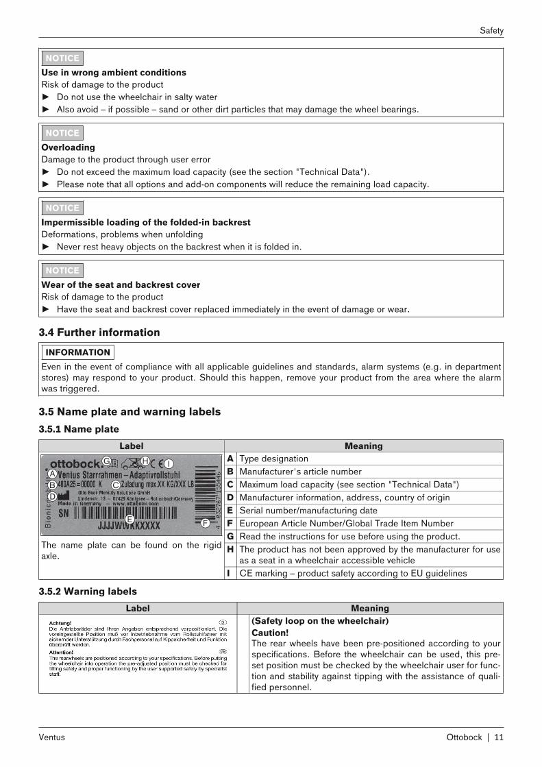
3.5 Name plate and warning labels3.5.1 Name plate
Label MeaningA Type designationB Manufacturer's article numberC Maximum load capacity (see section "Technical Data")D Manufacturer information, address, country of originE Serial number/manufacturing dateF European Article Number/Global Trade Item NumberG Read the instructions for use before using the product.H The product has not been approved by the manufacturer for use
as a seat in a wheelchair accessible vehicleThe name plate can be found on the rigidaxle.
I CE marking – product safety according to EU guidelines
3.5.2 Warning labelsLabel Meaning
(Safety loop on the wheelchair)Caution!The rear wheels have been pre-positioned according to yourspecifications. Before the wheelchair can be used, this preset position must be checked by the wheelchair user for function and stability against tipping with the assistance of qualified personnel.
Ottobock | 11Ventus
Safety
4 Delivery4.1 Scope of DeliveryThe wheelchair is delivered preassembled and with the rear wheels removed packed in a crate.The scope of delivery includes:• Preassembled wheelchair• 2 rear wheels• Footplate• Options according to the order• Instructions for Use (User)
4.2 Standard equipmentThe standard equipment includes:• Aluminium frame (open frame) with castor attachment device• Fold-down back• Single-panel footrest• Aluminium side panels• Calf strap• "Standard" seat upholstery• Rear wheels with quick-release axles• Sliding and clamping rear wheel attachment devices (sliders)• Wheel locks• Castor wheel in castor fork with threaded axle, adjustable castor journal• Push handlesThe seat cushion is not part of the standard equipment.
4.3 OptionsThe standard model can be fitted to the user's personal requirements thanks to a large range of options. For use ofthese options: see Page 14.
4.4 StorageThe wheelchair must be stored dry. The ambient temperature must be maintained between -10°C and +40°C.Wheelchairs with PU tyres should not be stored for prolonged periods with the knee-lever brake applied as thetyres could be deformed.
INFORMATIONTyres contain chemical substances that can react with other chemical substances (such as cleaning agents,acids, etc.).
5 Preparation for Use5.1 Assembly
CAUTIONExposed pinch pointsRisk of crushing or pinching the fingers due to incorrect handling► When folding out the backrest, only grip by the specified components.
12 | Ottobock
Delivery
Ventus

CAUTIONFailure to check that the wheelchair is ready for useRisk of falling, tipping of the user► Before using the wheelchair for the first time, check the pre-settings with the support of the qualified person
nel.► After every assembly, check the proper mounting of the rear wheels. The wheel axles must be securely locked
in the fitting.► Pay attention in particular to the stability against tipping, free running of the rear wheel and correct function of
the brakes.► Check the tyre inflation pressure. The correct air pressure is printed on the sidewall of the tyre. For rear
wheels, the minimum air pressure is 7 bar. Ensure that both tyres are inflated to the same pressure.
INFORMATIONFor details of weights of the individual parts, see the section "Technical Data".For disassembly and transport, see the section "Disassembly/Transport".
A few simple steps are sufficient for preparing the wheelchair for use:1) Fold down the backrest (see fig. 2):
→ Pull the backrest cable until the locking mechanism releases.→ Fold the backrest rearwards until the locking bolts lock in on both sides.
2) Fold out the folded-in side panels:→ Fold the side panels outwards by 90° (see fig. 3). → Fold the side panels downwards into the guides of the side panel supports (see fig. 4).
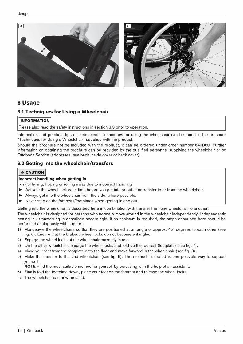
3) Attach the rear wheels to the quick-release axle housings:→ Press in the button on the quick-release axle (see fig. 5). → Attach the rear wheel to the quick-release axle housing and release the button on the quick-release axle.→ The quick-release axles must not be able to be removed after the pushbutton has been released.→ NOTE: For the "lock-release assist" option, see the section "Rear Wheels".
4) If necessary: Fit the seat cushion. The seat cushion is secured against sliding by being pressed on to thehook-and-loop fastener (see Page 16).
5) If necessary: Fasten the calf strap to the frame tube above the castor attachment device (see Page 15).
2 3
Ottobock | 13Ventus
Preparation for Use
4 5
6 Usage6.1 Techniques for Using a Wheelchair
INFORMATIONPlease also read the safety instructions in section 3.3 prior to operation.
Information and practical tips on fundamental techniques for using the wheelchair can be found in the brochure"Techniques for Using a Wheelchair" supplied with the product.Should the brochure not be included with the product, it can be ordered under order number 646D60. Furtherinformation on obtaining the brochure can be provided by the qualified personnel supplying the wheelchair or byOttobock Service (addresses: see back inside cover or back cover).
6.2 Getting into the wheelchair/transfers
CAUTIONIncorrect handling when getting inRisk of falling, tipping or rolling away due to incorrect handling► Activate the wheel lock each time before you get into or out of or transfer to or from the wheelchair.► Always get into the wheelchair from the side, where possible. ► Never step on the footrests/footplates when getting in and out.
Getting into the wheelchair is described here in combination with transfer from one wheelchair to another. The wheelchair is designed for persons who normally move around in the wheelchair independently. Independentlygetting in / transferring is described accordingly. If an assistant is required, the steps described here should beperformed analogously with support:1) Manoeuvre the wheelchairs so that they are positioned at an angle of approx. 45° degrees to each other (see
fig. 6). Ensure that the brakes / wheel locks do not become entangled.2) Engage the wheel locks of the wheelchair currently in use.3) On the other wheelchair, engage the wheel locks and fold up the footrest (footplate) (see fig. 7). 4) Move your feet from the footplate onto the floor and move forward in the wheelchair (see fig. 8).5) Make the transfer to the 2nd wheelchair (see fig. 9). The method illustrated is one possible way to support
yourself.NOTE Find the most suitable method for yourself by practising with the help of an assistant.
6) Finally fold the footplate down, place your feet on the footrest and release the wheel locks. → The wheelchair can now be used.
14 | Ottobock
Usage
Ventus

6 7
8 9
6.3 Information on use6.3.1 FootrestsThe user's feet can be placed on the footrest.The height of the footrest has been adjusted by qualified personnel to the length of the user's lower leg. The angle of the footplate has been set by the qualified personnel so that it allows the ankles to rest in a comfortable position.
6.3.1.1 Adjusting the footrest (footplate)The heights and angles of the "Angle-adjustable" footrest (see fig. 10) and footrest for short lower leg lengths (notpictured) can be adjusted by the qualified personnel. It is also possible to install heel blocks on both sides to stopthe feet from sliding into the area around the castor wheels.The "Fixed" footplate (see fig. 11) can have its height adjusted by the qualified personnel.Subsequent adjustments may be made only by qualified personnel.
10 11
6.3.1.2 Fastening / removing the calf strapThe calf strap offers additional support to the user's legs. It can be removed for cleaning.
Ottobock | 15Ventus
Usage

Fastening the calf strap1) Guide the calf strap around the frame tube above the castor attachment device (see fig. 12, item 1).2) Close the hook-and-loop closure (see fig. 12, item 2).
Removing the calf strap1) Open the hook-and-loop closure. 2) Remove the calf strap from the frame tube.
12
6.3.2 Seat cushion / backrest upholstery
CAUTIONSeat cushion or backrest cover may igniteUser may sustain burns► The seat cushion and backrest cover are not highly flammable, but there is a possibility they may catch fire.
Therefore utmost caution is required near open flame.► Keep away from any sources of fire, especially burning cigarettes.
NOTICEWear of the seat and backrest coverRisk of damage to the product► Have the seat and backrest cover replaced immediately in the event of damage or wear.
The seat cushion and the backrest upholstery ensure pressure relief during use of the wheelchair. They have beenchosen in advance by the qualified personnel according to the needs of the user.
6.3.2.1 Fastening / removing the seat cushionIf the seat upholstery is adjustable the seat cushion and seat pad can be removed for cleaning.1) Remove the seat cushion from the seat pad (see fig. 13).2) Pull the seat pad upwards from the hook-and-loop fastener and remove it (see fig. 14).3) After cleaning:
→ Secure the seat pad to the seat upholstery by means of the hook-and-loop fastener with edges aligned (seefig. 14).
→ Place the seat cushion on the seat pad (see fig. 13). The seat cushion is secured against sliding by beingpressed on to the hook-and-loop fastener.
16 | Ottobock
Usage
Ventus

13 14
6.3.2.2 Fastening / removing the backrest padThe backrest pad (adjustable) can be removed for cleaning.1) Remove the seat cushion.2) Fold the seat pad forwards away from the hook-and-loop fastener (see fig. 15, item 1).3) Pull the flap of the backrest pad off the hook-and-loop fastener (see fig. 15, item 2) and let it hang down. 4) Remove the backrest pad.5) After cleaning:
→ Put the backrest pad back on. Place the kink in the backrest pad at the top. The "V" in the pad (see fig. 16,item 1) shows exactly where the kink is.
→ Pull the backrest pad flap tightly downwards (see fig. 17).→ Pull the part of the flap that can be fastened forwards and fasten tightly to the seat upholstery (see fig. 15,
item 2).INFORMATION: The part of the flap that can be fastened prevents sliding or falling through thegaps between the straps and protects against draughts.
6) Fasten the seat pad (see fig. 15, item 1) and the seat cushion.
15 16
17
Ottobock | 17Ventus
Usage
6.3.3 Side panels
CAUTIONPinching at the side panelsRisk of pinching and crushing of the hands► Pay attention not to pinch parts of your body between the side or frame parts.
The side panels protect the user and his/her clothing from getting dirty. If armrests have been installed on the wheelchair, they offer the user additional support for the forearms.
6.3.3.1 Adjusting the armrest height
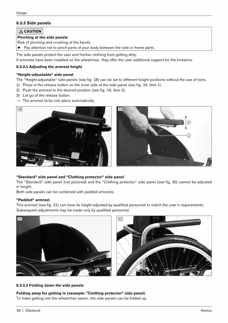
"Height-adjustable" side panelThe "Height-adjustable" side panels (see fig. 18) can be set to different height positions without the use of tools.1) Press in the release button on the inner side of the side panel (see fig. 19, item 1).2) Push the armrest to the desired position (see fig. 19, item 2). 3) Let go of the release button. → The armrest locks into place automatically.
18 19
"Standard" side panel and "Clothing protector" side panelThe "Standard" side panel (not pictured) and the "Clothing protector" side panel (see fig. 20) cannot be adjustedin height. Both side panels can be combined with padded armrests.
"Padded" armrestThis armrest (see fig. 21) can have its height adjusted by qualified personnel to match the user's requirements. Subsequent adjustments may be made only by qualified personnel.
20 21
6.3.3.2 Folding down the side panels
Folding away for getting in (example: "Clothing protector" side panel)To make getting into the wheelchair easier, the side panels can be folded up.
18 | Ottobock
Usage
Ventus

1) Pull the side panels up out of the guides of the side panel supports (see fig. 22).2) Fold the side panels up by 90° (see fig. 23).3) After getting in, fold the side panels down again into the guides of the side panel supports.
22 23
Folding for transport (example: "Standard" side panel)The side panels can be folded in for transport.1) Fold the side panels up out of the side panel supports (see fig. 24).2) Fold the side panels inwards by 90° (see fig. 25).3) After assembling the wheelchair, fold the side panels down again into the guides of the side panel supports.
24 25
6.3.3.3 Removing the "Padded" armrestTo make getting in and transporting the wheelchair easier, the armrests can be folded away or removed.1) Pull the armrests up out of the holders (see fig. 26).2) Fold the armrests away by 90° (see fig. 27) or remove them.3) After getting in, slide the armrests down into the holders again.
26 27
Ottobock | 19Ventus
Usage

6.3.3.4 Adjusting a Channel Forearm Pad with Swivel Unit
INFORMATIONAfter adjusting the swivel unit, please always make sure that the lock pins have safely snapped in place.
The swivel unit allows the support angle and the rotation setting of a channel forearm pad to be adjusted independently.
Adjusting the support angle1) Pull the release button outwards (see fig. 28, item 1).2) Lift up the channel forearm pad at the front end and adjust it to the desired angle (see fig. 28, item 2).3) Let go of the release button. The channel forearm pad will be secured in its position.
Adjusting the rotation setting in 15° steps1) Pull the release button downwards (see fig. 29, item 1).2) Move the channel forearm pad to the desired rotation setting (see fig. 29, item 2).3) Let go of the release button. The channel forearm pad will be secured in its position.
Continuously adjusting the rotation setting1) Pull the release button downwards (see fig. 29, item 1).2) Turn the release button 90° (not pictured). In this position the channel forearm pad can be rotated freely.3) Move the channel forearm pad to the desired rotation setting (see fig. 29, item 2).4) Let go of the release button. The channel forearm pad will be secured in its position.
28 29
6.3.4 Push handlesThe push handles make pushing the wheelchair easier for the attendant. Some of the push handle designs allow the height to be adjusted to suit the needs of the attendant.
6.3.4.1 Adjusting the push handlesThe "standard" push handle (see fig. 30) and the "folding" push handle (not illustrated) cannot be adjusted inheight. The height of the "height-adjustable" (see fig. 31) and "height-adjustable/removable" push handles (not illustrated)can be adjusted for easier pushing by an attendant.1) Release the clamping lever.2) Adjust the height of the push handle.3) Lock the clamping lever securely.
INFORMATION: Both push handles must be adjusted to the same height.
20 | Ottobock
Usage
Ventus

30 31
6.3.5 Rear wheels
CAUTIONHeat development when braking with push ringsRisk of burns to the hands► Wear leather gloves when travelling at high speeds.
CAUTIONPinching in exposed drive partsRisk of pinching and crushing of the hands► To avoid hand injuries, do not grasp between the rear wheel and the knee lever lock when driving your wheel
chair.► Do not reach between the spokes of the rear wheel.
The wheelchair is moved, steered and stopped with the help of the push rings on the rear wheels.To make transport easier, the rear wheels can be taken off the wheelchair.
6.3.5.1 Removing / fitting the rear wheels
Rear wheels with quick-release axles1) Grip the area between the spokes near the hub with your fingers.2) Use your thumb to press the pushbutton on the quick-release axle.3) Pull off / push on the rear wheel. The quick-release axles must not be able to be removed after the pushbutton
has been released.
32
Rear wheels with lock-release assistThe lock-release assist allows the rear wheels to be installed even with heavily restricted movement of the arms andhands.1) Open the lock-release assist according to the grip setting (see fig. 33= push down; see fig. 34 = pull up). The
lock is open when the bar is horizontal (90° position).2) Pull off/push on the rear wheel.
Ottobock | 21Ventus
Usage

3) Close the lock-release assist (see fig. 33, see fig. 34 = pull up or push down).NOTE: The wheels must fit on to the wheel attachments without there being any play after closure.
33 34
6.3.6 Castors / castor forks
CAUTIONIncorrect caster wheel positioningRisk of falling or tipping when leaning forward in the wheelchair► Prior to activities that require you to bend forward in the wheelchair (e.g. tying your shoes), maximise the sta
bility of the wheelchair. In order to do so, push the wheelchair backwards until the caster wheels turn forward.
The combination of castor wheels and castor forks ensures the ability to hold a straight line and navigate curves.The different castor wheels (e.g. light rollers, design rollers, full rubber rollers, skate rollers) or castor forks (e.g.castor forks with or without suspension) have been chosen by the qualified personnel according to the needs of theuser.
35
6.3.7 Brakes
CAUTIONImproper use of the wheel lockFalling due to abrupt braking, rolling away of the wheelchair, crushing the hands► Do not use the knee lever wheel lock as a driving brake.► Always engage the wheel lock on both sides.► When parking on uneven ground or during transfers (e.g. into a car), secure the wheelchair by activating the
knee lever wheel lock.► Do not reach between the rear wheel and the knee lever wheel lock when driving the wheelchair.► Ensure the knee lever wheel lock is properly adjusted (approx. 5 mm gap to the tyres, technical changes
reserved) and the tyre pressure is sufficient.
The wheel locks secure the parked wheelchair against rolling away.
22 | Ottobock
Usage
Ventus

6.3.7.1 Using the knee lever wheel lock
Activating / deactivating the "Standard" / "Upgrade" knee lever wheel lock1) Push the handle of the knee lever wheel lock forward (see fig. 36).
→ The wheel lock bolt secures the wheel.2) Pull the wheel lock lever upwards (see fig. 37).
→ The wheel lock lever releases the wheel.
36 37
Activating / deactivating the scissor wheel lock► Reach under the seat and pull the handle of the scissor wheel lock rearwards from the side (see fig. 38).→ The wheel lock bolt secures the wheel.► Pull the handle of the scissor wheel lock forwards to unfold (see fig. 39).→ The wheel lock bolt releases the wheel.
38 39
6.3.8 Anti-tipper / tip-assist
WARNINGAnti-tipper not activated Risk of falling, tipping to the rear► Ensure that an installed anti-tipper is activated before travelling over obstacles and on inclines. ► The anti-tipper must engage audibly before use. Proper engagement must be checked by the user or an
accompanying person.► The use of an anti-tipper is urgently recommended for persons with legs amputated above the knee.
WARNINGIncorrectly adjusted anti-tipperRisk of falling as a result of incorrectly adjusted anti-tipper.► The anti-tipper may only be adjusted by qualified personnel.
Ottobock | 23Ventus
Usage
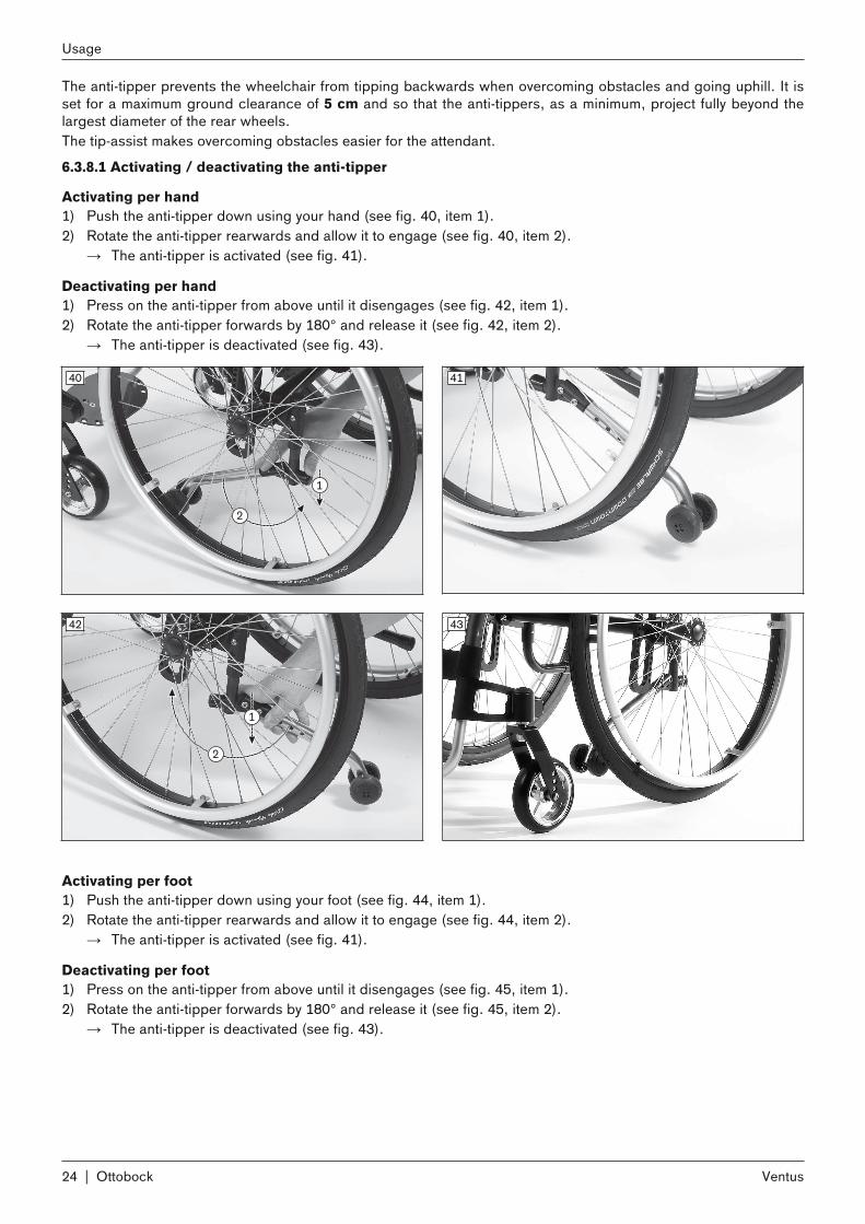
The anti-tipper prevents the wheelchair from tipping backwards when overcoming obstacles and going uphill. It isset for a maximum ground clearance of 5 cm and so that the anti-tippers, as a minimum, project fully beyond thelargest diameter of the rear wheels.The tip-assist makes overcoming obstacles easier for the attendant.
6.3.8.1 Activating / deactivating the anti-tipper
Activating per hand1) Push the anti-tipper down using your hand (see fig. 40, item 1).2) Rotate the anti-tipper rearwards and allow it to engage (see fig. 40, item 2).
→ The anti-tipper is activated (see fig. 41).
Deactivating per hand1) Press on the anti-tipper from above until it disengages (see fig. 42, item 1).2) Rotate the anti-tipper forwards by 180° and release it (see fig. 42, item 2).
→ The anti-tipper is deactivated (see fig. 43).
40 41
42 43
Activating per foot1) Push the anti-tipper down using your foot (see fig. 44, item 1).2) Rotate the anti-tipper rearwards and allow it to engage (see fig. 44, item 2).
→ The anti-tipper is activated (see fig. 41).
Deactivating per foot1) Press on the anti-tipper from above until it disengages (see fig. 45, item 1).2) Rotate the anti-tipper forwards by 180° and release it (see fig. 45, item 2).
→ The anti-tipper is deactivated (see fig. 43).
24 | Ottobock
Usage
Ventus

44 45
6.3.8.2 Using the tip-assist1) At an obstacle, place one foot on the tip-assist (see fig. 46) and push down.2) You can then easily tip the wheelchair slightly by simultaneously pressing down on the push handles.
46
6.3.9 Wheelbase extension
Wheelbase extension for the handbike adaption
CAUTIONInactive wheel lock after adjustment of rear wheelsRisk of falling or collision due to lack of brake functionality► Please note that the wheel locks on the wheelchair no longer function after the rear wheels have been adjus
ted for the wheelbase extension (adjustment for handbike adaption).► Check the braking function of the wheel locks on the handbike each time before using the adapted handbike.
This wheelbase extension option version is intended especially for the adaption of handbikes (see fig. 47). For an adapted handbike the rear wheels must be moved from the front axle (see fig. 48, item 1) to the rear axle(see fig. 48, item 2).After the rear wheels have been moved, the wheel lock on the wheelchair can no longer be used.
INFORMATIONAfter the rear wheels have been moved, the "Clothing protector" side panels can only be slightly folded outagainst the tyres (see fig. 50).
Ottobock | 25Ventus
Usage

47 48
Wheelbase extension for a permanently passive wheelbaseThis wheelbase extension option version offers the user a permanently large wheelbase (see fig. 49). This allowscharacteristics such as a particularly high wheelchair stability for particularly safety-conscious or inexperiencedusers.The wheel lock on the wheelchair has been installed by qualified personnel and can continue to be used.
INFORMATIONAfter the rear wheels have been moved, the "Clothing protector" side panels can only be slightly folded outagainst the tyres (see fig. 50).
49 50
6.3.10 Shock absorber systemThe shock absorber system absorbs loading peaks, for example when driving over steps or curbs or on unevenground.
51
26 | Ottobock
Usage
Ventus

6.3.11 Headrests and neckrestsThe user may adjust the movable blocks of the headrest according to his/her preferences. Adjust the movableblocks into the desired position and tighten the wrench bolts to fix the headrest in place.The option has been preset by the qualified personnel.
6.3.12 Additional optionsThe product may be equipped with additional options.The options are firmly mounted to the product by qualified personnel or the manufacturer and are pre-adjusted byqualified personnel at delivery.
6.4 Disassembly / TransportNOTICE
Impermissible loading of the folded-in backrestDeformations, problems when unfolding► Never rest heavy objects on the backrest when it is folded in.
The wheelchair must be prepared for transport in a passenger vehicle. The small folded size (with the backrest folded) allows the product to be stored in a small vehicle trunk or on thepassenger seat.1) Fold in the side panels (see fig. 52):
→ Fold back the side panels out of the side panel supports.→ Fold the side panels inwards by 90°.
2) Remove the seat cushion from the hook-and-loop fastener.3) Remove the rear wheels:
→ Press in the button on the quick-release axle (see fig. 53). → Pull the rear wheel outwards out of the quick-release axle housing.
NOTE: For the "lock-release assist" option, see the section "Rear Wheels".4) Fold in the backrest (see fig. 54):
→ Pull the backrest cable until the locking mechanism releases.→ Fold the backrest down towards the seat surface and press until the locking bolts lock in on both sides.
5) Place the wheelchair in its folded-up state in the vehicle (see fig. 55).
52 53
Ottobock | 27Ventus
Usage

54 55
6.5 Use in a wheelchair accessible vehicle
WARNINGUnallowable use in a wheelchair accessible vehicleRisk of serious injury when using the product as a seat ► The product has not been approved by the manufacturer for use as a seat in a wheelchair accessible vehicle.► Always use the seats installed in the wheelchair accessible vehicle with the corresponding vehicle restraint
systems.
The product may not be used as a seat in a wheelchair accessible vehicle.
6.6 Care6.6.1 Cleaning1) Clean the padding and upholstery with warm water and a mild detergent. 2) Remove any spots with a sponge or a soft brush. 3) Rinse with clear water and let the components dry.
Important information on cleaning• Do not use any aggressive cleaners, solvents or hard brushes etc. • Clean plastic parts, frame parts and the chassis and wheels with a mild cleaner and a damp cloth. Dry thor
oughly afterwards.• Do not immerse in water. Components are not machine-washable.
6.6.2 Disinfection► Wipe all parts of the wheelchair with a disinfectant.
Important information about disinfecting• Only use water-based disinfectants. Observe the instructions for use provided by the manufacturer.• Thoroughly clean the pads and handles before disinfecting.
7 Maintenance/Repair7.1 MaintenanceThe product bears the CE marking. The manufacturer hereby guarantees that this medical device as a whole conforms to the requirements of the European Directive for Medical Devices 93/42/EEC.• The function of the product should be checked before each use.• If defects are found, especially instability of the product or altered driving characteristics as well as problems
with the user's seating position or the stability of the seat, the product should not be used. The specialist dealer must be contacted promptly in order to correct these defects.
• This also applies if loose, worn, bent or damaged components are identified.• Some maintenance tasks can be carried out to a certain extent by the user at home (see the section "Mainten
ance Tasks").• The manufacturer also recommends regular maintenance every 12 months by an authorised dealer.
28 | Ottobock
Maintenance/Repair
Ventus

• Failure to maintain the product can lead to serious or life-threatening injury to the user of the product.• Service and repairs may only be carried out by authorised dealers or the manufacturer. This will ensure that
only Ottobock spare parts are used for repairs.
7.1.1 Maintenance intervalsThe functions described below must be checked by the user or an attendant at the specified intervals:
Inspection task Before each use Monthly QuarterlyFunctional test of the wheel locks XSagging of seat or backrest upholstery XFootplate stability XVisual inspection of wear parts (e.g. tyres, bearings) XSoiling of bearings XDamage to the push ring XAir pressure (printed on the tyre sidewall) XWear to the folding mechanism of the backrest XCheck of the spoke tension on the rear wheels XCheck of all bolted connections X
7.1.2 Scopes of maintenanceTo ensure smooth operation at all times, users or attendants with some technical skills can maintain some parts ofthe wheelchair:• Hair and dirt frequently collect between the caster fork and the caster wheel and make the caster wheels
harder to manoeuvre as time goes by. Remove the caster wheel and thoroughly clean the fork and caster wheelusing a mild household cleaner.CAUTION: In order to avoid impairing the tip resistance of the product, the caster wheel journal anglemust not be changed during this process.
• The rear wheels are equipped with quick-release axles. To keep this system operational, ensure that no dirtadheres to the quick-release axle or axle housing. Periodically lubricate the quick-release axle very lightly withresin-free sewing machine oil.
• If the wheelchair becomes wet, it should be rubbed dry again.• Bolted connections must be periodically checked for tightness, especially during the initial period of use or
after adjustments have been made to the wheelchair. If a screw connection loosens repeatedly, contact thespecialist dealer promptly.
7.2 Repair7.2.1 Inner tube/rim tape/tyre replacement
INFORMATIONWhen driving outdoors, always carry a repair kit and tyre pump (when using pneumatic tyres) in case of emergency. Suitable tyre pumps are listed on the order form and are supplied with the product. An alternative is tyre foam,which fills your tyre and then hardens (available from bicycle shops etc.).
Repairing flat tyres requires only the necessary tools and minimal technical skills. Users may change tyres themselves if they wish:
Removal and Preparing for Installation1) Carefully remove the tyre from the rim using appropriate tools.
INFORMATION: Take care not to damage the rim or the inner tube.2) Unscrew the valve nut from the valve and remove the tube.3) Repair the tube according to the directions in the repair kit or replace it with a new tube.4) Before fitting the tyre again, inspect the rim bed and tyre inner wall for foreign objects. This could have caused
the puncture. 5) Before installing the tube, check that the rim band is in proper condition. The rim band protects the tube from
being damaged by the ends of the spokes.
Ottobock | 29Ventus
Maintenance/Repair

56 57
Replacing the Rim Band (only when necessary)1) If the rim band needs to be replaced, remove it from the rim.2) Install the new rim band on the inside of the rim, making sure the valve opening is in the right position. 3) Glue the rim band in place if this is intended. Ensure that all spoke ends are covered.
Installing the Tube and Tyre1) Behind the valve, push one side of the tyre over the edge of the rim. 2) Slightly inflate the tube until it starts to assume its round shape. 3) Unscrew the valve nut from the tube and push the valve through the valve opening in the rim.4) Insert the tube into the tyre. 5) Mount the other side of the tyre on the rim, starting from the position across the valve. Ensure that the tube is
not pinched between the tyre and rim during this process.
58 59
Inflating the Tube1) Ensure that the valve is positioned perpendicularly for proper positioning of the tube and tyre in the region of
the valve. 2) Firmly screw on the valve nut.3) Inflate the tube so that the tyre can still be pressed in easily with your thumb.
INFORMATION: If the circumferential lines on the two sides of the tyre are both at an even distancefrom the rim, the tyre is centred. If not, let some air out and realign the tyre.
4) Inflate the tube to the maximum pressure specified by the tyre manufacturer (see information printed on thecasing).
5) Firmly screw the valve cap onto the valve.
8 Disposal8.1 Disposal InformationReturn the product to the specialist dealer for disposal.
30 | Ottobock
Disposal
Ventus

All components of the product must be disposed of properly in accordance with the respective national environmental regulations.
9 Legal InformationAll legal conditions are subject to the respective national laws of the country of use and may vary accordingly.
9.1 Service LifeBased on market observations and the current state of technology, the manufacturer has calculated that theproduct can be used for a period of 4 years, provided that it is used properly and that the service and maintenanceinstructions are observed. Periods of storage at the specialist dealer or with the paying party are not included inthis period. However, we would like to emphasise that the product is reliable far beyond this defined period of time, providedthat it is cared for and maintained properly.If the service life is reached, the user or a responsible attendant should contact the qualified personnel who fittedthe product or the manufacturer's service (see inside rear cover or back page for address).
9.2 LiabilityThe manufacturer will only assume liability if the product is used in accordance with the descriptions and instructions provided in this document. The manufacturer will not assume liability for damage caused by disregard of thisdocument, particularly due to improper use or unauthorised modification of the product.
9.3 CE ConformityThis product meets the requirements of the European Directive 93 / 42 / EEC for medical devices. This product hasbeen classified as a class I device according to the classification criteria outlined in Annex IX of the directive. Thedeclaration of conformity was therefore created by the manufacturer with sole responsibility according to Annex VIIof the directive.
9.4 WarrantyFurther information on the warranty terms and conditions can be obtained from the qualified personnel that has fitted this product or the manufacturer's service (see inside back cover for addresses).
9.5 TrademarksAll product names mentioned in this document are subject without restriction to the respective applicable trademark laws and are the property of the respective owners.All brands, trade names or company names may be registered trademarks and are the property of the respectiveowners.Should trademarks used in this document fail to be explicitly identified as such, this does not justify the conclusionthat the denotation in question is free of third-party rights.
10 Technical DataGeneral information
VentusMaximum load capacity [kg] 100 (for seat width 280 - 440)
140 (for seat width 460 - 500)Weight [kg](for seat width 440 mm; 4" full rubber caster wheels, 24"hollow rim)
approx. 12.51)
Transport weights [kg](for seat width: 440 mm; 4" full rubber caster wheels)
Frame: 7.5 – 8.81)
Rear wheel 24": 3.71)
Seat width [mm] 280 – 440 (max. load capacity 100 kg)280 – 500 (max. load capacity 140 kg)
Seat depth [mm] 300 – 5002)
Max. total height [mm](for rear seat height: 500 mm; back height 500 mm; pushhandle)
1050
Ottobock | 31Ventus
Legal Information
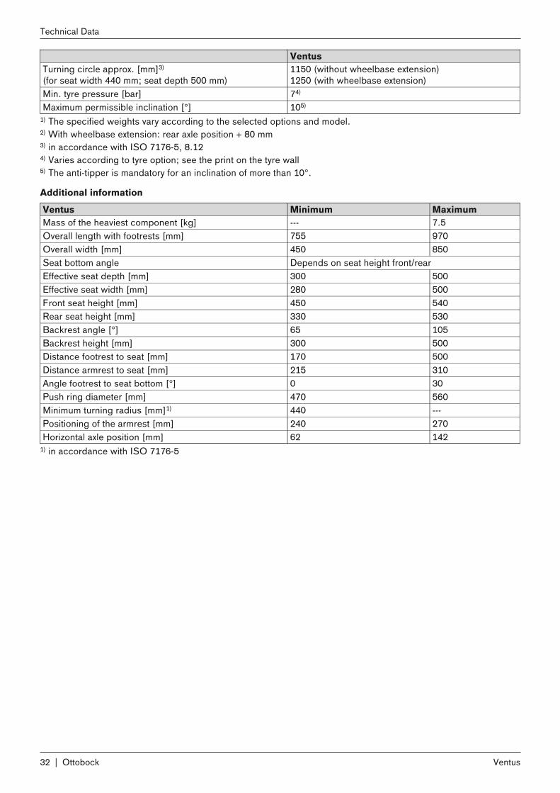
VentusTurning circle approx. [mm]3)
(for seat width 440 mm; seat depth 500 mm) 1150 (without wheelbase extension)1250 (with wheelbase extension)
Min. tyre pressure [bar] 74)
Maximum permissible inclination [°] 105)
1) The specified weights vary according to the selected options and model.2) With wheelbase extension: rear axle position + 80 mm3) in accordance with ISO 7176-5, 8.124) Varies according to tyre option; see the print on the tyre wall5) The anti-tipper is mandatory for an inclination of more than 10°.
Additional information
Ventus Minimum MaximumMass of the heaviest component [kg] --- 7.5Overall length with footrests [mm] 755 970Overall width [mm] 450 850Seat bottom angle Depends on seat height front/rearEffective seat depth [mm] 300 500Effective seat width [mm] 280 500Front seat height [mm] 450 540Rear seat height [mm] 330 530Backrest angle [°] 65 105Backrest height [mm] 300 500Distance footrest to seat [mm] 170 500Distance armrest to seat [mm] 215 310Angle footrest to seat bottom [°] 0 30Push ring diameter [mm] 470 560Minimum turning radius [mm]1) 440 ---Positioning of the armrest [mm] 240 270Horizontal axle position [mm] 62 142
1) in accordance with ISO 7176-5
32 | Ottobock
Technical Data
Ventus

Ottobock | 33Ventus

Ventus34 | Ottobock

Kundenservice/Customer Service
EuropeOtto Bock HealthCare Deutschland GmbHMax-Näder-Str. 15 · 37115 Duderstadt · GermanyT +49 5527 848-3433 · F +49 5527 [email protected] · www.ottobock.de
Otto Bock Healthcare Products GmbHKaiserstraße 39 · 1070 Wien · AustriaT +43 1 5269548 · F +43 1 [email protected] · www.ottobock.at
Otto Bock Adria Sarajevo D.O.O.Omladinskih radnih brigada 571000 Sarajevo · Bosnia-HerzegovinaT +387 33 766200 · F +387 33 [email protected] · www.ottobockadria.com.ba
Otto Bock Bulgaria Ltd.41 Tzar Boris III‘ Blvd. · 1612 Sofia · BulgariaT +359 2 80 57 980 · F +359 2 80 57 [email protected] · www.ottobock.bg
Otto Bock Suisse AGPilatusstrasse 2 · CH-6036 DierikonT +41 41 455 61 71 · F +41 41 455 61 [email protected] · www.ottobock.ch
Otto Bock ČR s.r.o.Protetická 460 · 33008 Zruč-Senec · Czech RepublicT +420 377825044 · F +420 [email protected] · www.ottobock.cz
Otto Bock Iberica S.A.C/Majada, 1 · 28760 Tres Cantos (Madrid) · SpainT +34 91 8063000 · F +34 91 [email protected] · www.ottobock.es
Otto Bock France SNC4 rue de la Réunion - CS 9001191978 Courtaboeuf Cedex · FranceT +33 1 69188830 · F +33 1 [email protected] · www.ottobock.fr
Otto Bock Healthcare plc32, Parsonage Road · Englefield GreenEgham, Surrey TW20 0LD · United KingdomT +44 1784 744900 · F +44 1784 [email protected] · www.ottobock.co.uk
Otto Bock Hungária Kft.Tatai út 74. · 1135 Budapest · HungaryT +36 1 4511020 · F +36 1 [email protected] · www.ottobock.hu
Otto Bock Adria d.o.o.Dr. Franje Tuđmana 14 ·10431 Sveta Nedelja · CroatiaT +385 1 3361 544 · F +385 1 3365 [email protected] · www.ottobock.hr
Otto Bock Italia Srl UsVia Filippo Turati 5/7 · 40054 Budrio (BO) · ItalyT +39 051 692-4711 · F +39 051 [email protected] · www.ottobock.it
Otto Bock Benelux B.V.Ekkersrijt 1412 · 5692 AKSon en Breugel · The NetherlandsT +31 499 474585 · F +31 499 [email protected] · www.ottobock.nl
Industria Ortopédica Otto Bock Unip. Lda.Av. Miguel Bombarda, 21 - 2º Esq.1050-161 Lisboa · PortugalT +351 21 3535587 · F +351 21 [email protected]
Otto Bock Polska Sp. z o. o.Ulica Koralowa 3 · 61-029 Poznań · PolandT +48 61 6538250 · F +48 61 [email protected] · www.ottobock.pl
Otto Bock Romania srlŞos de Centura Chitila - Mogoşoia Nr. 3077405 Chitila, Jud. Ilfov · RomaniaT +40 21 4363110 · F +40 21 [email protected] · www.ottobock.ro
OOO Otto Bock Servicep/o Pultikovo, Business Park „Greenwood“,Building 7, 69 km MKAD143441 Moscow Region/Krasnogorskiy RayonRussian FederationT +7 495 564 8360 · F +7 495 564 [email protected] · www.ottobock.ru
Otto Bock Scandinavia ABKoppargatan 3 · Box 623 · 60114 Norrköping · SwedenT +46 11 280600 · F +46 11 [email protected] · www.ottobock.se
Otto Bock Slovakia s.r.o.Röntgenova 26 · 851 01 Bratislava 5 · Slovak RepublicT +421 2 32 78 20 70 · F +421 2 32 78 20 [email protected] · www.ottobock.sk
Otto Bock Sava d.o.o.Industrijska bb · 34000 Kragujevac · Republika SrbijaT +381 34 351 671 · F +381 34 351 [email protected] · www.ottobock.rs
Otto Bock Ortopedi ve Rehabilitasyon Tekniği Ltd. Şti.Ali Dursun Bey Caddesi · Lati Lokum SokakMeriç Sitesi B Block No: 6/134387 Mecidiyeköy-İstanbul · TurkeyT +90 212 3565040 · F +90 212 [email protected] · www.ottobock.com.tr
AfricaOtto Bock Algérie E.U.R.L.32, rue Ahcène Outaleb - Coopérative les MimosasMackle-Ben Aknoun · Alger · DZ AlgérieT +213 21 913863 · F +213 21 [email protected] · www.ottobock.fr
Otto Bock Egypt S.A.E.28 Soliman Abaza St. Mohandessein - Giza · EgyptT +202 330 24 390 · F +202 330 24 [email protected] · www.ottobock.com.eg
Otto Bock South Africa (Pty) LtdBuilding 3 Thornhill Office Park · 94 Bekker RoadMidrand · Johannesburg · South AfricaT +27 11 312 [email protected]
AmericasOtto Bock Argentina S.A.Av. Belgrano 1477 · CP 1093Ciudad Autônoma de Buenos Aires · ArgentinaT +54 11 5032-8201 / [email protected]
Otto Bock do Brasil Tecnica Ortopédica Ltda.Alameda Maria Tereza, 4036, Bairro Dois CórregosCEP: 13.278-181, Valinhos-São Paulo · Brasil T +55 19 3729 3500 · F +55 19 3269 6061 [email protected] · www.ottobock.com.br
Otto Bock HealthCare Canada5470 Harvester Road Burlington, Ontario, L7L 5N5, CanadaT +1 289 288-4848 · F +1 289 [email protected] · www.ottobock.ca
Otto Bock HealthCare Andina Ltda.Calle 138 No 53-38 · Bogotá · ColombiaT +57 1 8619988 · F +57 1 [email protected] · www.ottobock.com.co
Otto Bock de Mexico S.A. de C.V.Prolongación Calle 18 No. 178-ACol. San Pedro de los PinosC.P. 01180 México, D.F. · MexicoT +52 55 5575 0290 · F +52 55 5575 [email protected] · www.ottobock.com.mx
Otto Bock HealthCareTwo Carlson Parkway North, Suite 100Minneapolis, MN 55447 · USAT +1 763 553 9464 · F +1 763 519 [email protected]
Asia/PacificOtto Bock Australia Pty. Ltd.Suite 1.01, Century Corporate Centre62 Norwest BoulevardeBaulkham Hills NSW 2153 · AustraliaT +61 2 8818 2800 · F +61 2 8814 [email protected] · www.ottobock.com.au
Beijing Otto Bock Orthopaedic Industries Co., Ltd.B12E, Universal Business Park10 Jiuxianqiao Road, Chao Yang DistrictBeijing, 100015, P.R. ChinaT +8610 8598 6880 · F +8610 8598 [email protected]
Otto Bock Asia Pacific Ltd.Unit 1004, 10/F, Greenfield Tower, Concordia Plaza 1 Science Museum Road, Tsim Sha TsuiKowloon, Hong Kong · China T +852 2598 9772 · F +852 2598 7886 [email protected] · www.ottobock.com
Otto Bock HealthCare India Pvt. Ltd.20th Floor, Express TowersNariman Point, Mumbai 400 021 · IndiaT +91 22 2274 5500 / 5501 / [email protected] · www.ottobock.in
Otto Bock Japan K. K.Yokogawa Building 8F, 4-4-44 ShibauraMinato-ku, Tokyo, 108-0023 · JapanT +81 3 3798-2111 · F +81 3 [email protected] · www.ottobock.co.jp
Otto Bock Korea HealthCare Inc.4F Agaworld Building · 1357-74, Seocho-dongSeocho-ku, 137-070 Seoul · KoreaT +82 2 577-3831 · F +82 2 [email protected] · www.ottobockkorea.com
Otto Bock South East Asia Co., Ltd.1741 Phaholyothin RoadKwaeng Chatuchark · Khet ChatucharkBangkok 10900 · ThailandT +66 2 930 3030 · F +66 2 930 [email protected] · www.ottobock.co.th
Other countriesOtto Bock HealthCare GmbHMax-Näder-Straße 15 · 37115 Duderstadt · GermanyT +49 5527 848-1590 · F +49 5527 [email protected] · www.ottobock.com

Template-Version: SB_2014-05-12 · FM483 · SB_210x297
Ottobock has a certified Quality Management System in accordance with ISO 13485.
Ihr Fachhändler | Your specialist dealer
Otto Bock Mobility Solutions GmbHLindenstraße 13 · 07426 Königsee-Rottenbach/Germanywww.ottobock.com
© O
ttobo
ck ·
647G
828=
EN-0
6-14
10