ventilation and safety of long and deep tunnels … · ventilation and safety of long and deep ......
TRANSCRIPT

1
Ventilation and Safety of Long and Deep Tunnels ‐ State of the Art and New Perspectives
Marco Bettelini and Samuel Rigert
Amberg Engineering Ltd., Regensdorf‐Watt, Switzerland
INTRODUCTION AND OBJECTIVES Long rail tunnels require in most cases powerful mechanical ventilations. Besides requirements related
to normal operation and maintenance, operational safety always requires a high level of smoke
management. Identifying the optimum ventilation concept is essential for achieving proper performance
and safety while keeping investment and operational cost at a reasonable level.
For the purpose of the present paper, long tunnels have a length of typically 20 km or more. This is
related to the European classification of trains (TSI 1303/2014), where the maximum distance from the
portals to a firefighting point and between firefighting points is limited to 20 km (only category B
passenger rolling stock allowed) or 5 km (general case). From TSI 1303/2014 it can be concluded, that
tunnels over 20 km require in any case emergency stations with complex mechanical ventilations.
Based on the experience arising from a number of recent projects in the European area, including in
particular Gotthard (GBT), Lötschberg, Lyon‐Tourin (LTF), Brenner (BBT) and Gibraltar, safety‐relevant
issues related to the ventilation of long railways tunnels are reviewed in this paper. Amberg Engineering
is directly involved in these challenging design tasks and can provide first‐hand experience and know‐
how.
As a particular highlight, special attention is devoted to the longest tunnel worldwide, the 57 km
long Gotthard Base Tunnel, which will be commissioned in 2016.
THE GOTTHARD BASE TUNNEL
Overview The Gotthard Base Tunnel will be commissioned in 2016 (official inauguration on the 1st of June and
beginning of regular operation on the 11th of December) and will be the worldwide longest tunnel. Its
complex and powerful ventilation system is very representative for many other long tunnels and is used
as reference in this paper. Therefore, a few key characteristics of the Gotthard Base Tunnel and its
ventilation system will be described in some detail in this initial chapter.
The Gotthard Base Tunnel (GBT) consists of two single‐track tunnel tubes with connecting galleries
every 312 meters. Two so‐called multi‐functional stations (MFS), located at roughly 1/3 and 2/3 of the
tunnel length, host the key equipment for normal and for emergency operation. At these locations,
double crossovers allow trains to switch from one tunnel tube to the other. An emergency station is
2
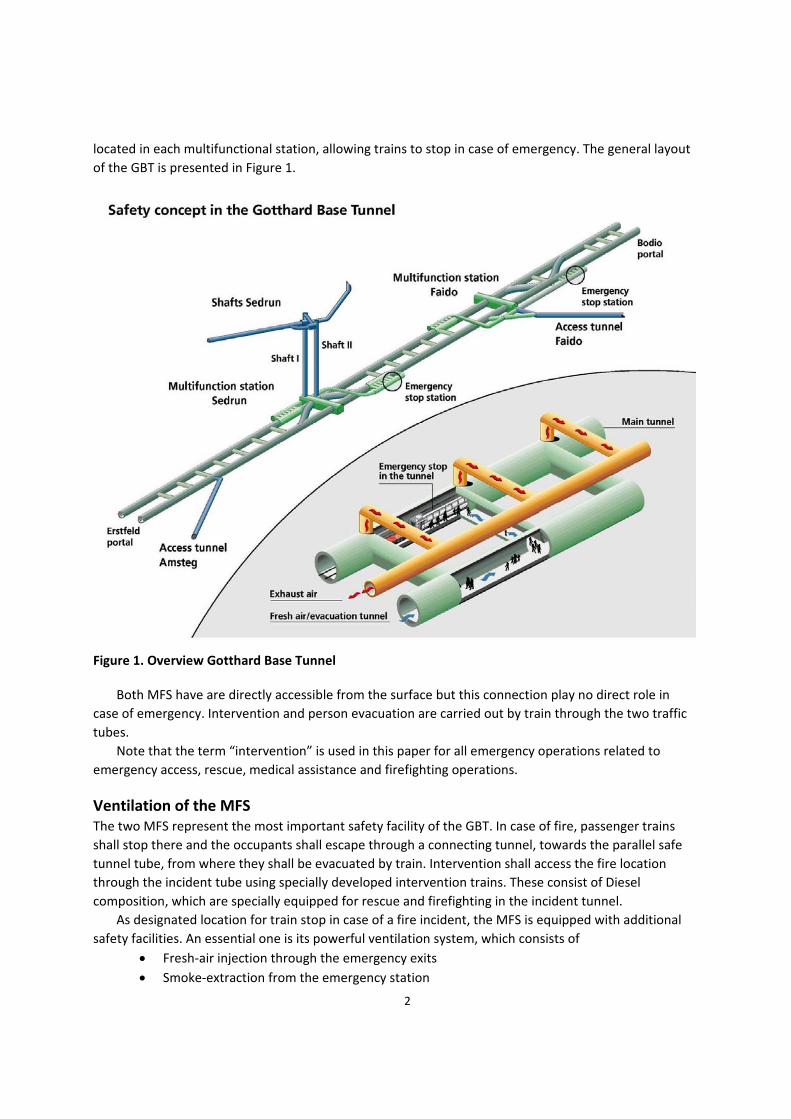
located in each multifunctional station, allowing trains to stop in case of emergency. The general layout
of the GBT is presented in Figure 1.
Figure 1. Overview Gotthard Base Tunnel
Both MFS have are directly accessible from the surface but this connection play no direct role in
case of emergency. Intervention and person evacuation are carried out by train through the two traffic
tubes.
Note that the term “intervention” is used in this paper for all emergency operations related to
emergency access, rescue, medical assistance and firefighting operations.
Ventilation of the MFS The two MFS represent the most important safety facility of the GBT. In case of fire, passenger trains
shall stop there and the occupants shall escape through a connecting tunnel, towards the parallel safe
tunnel tube, from where they shall be evacuated by train. Intervention shall access the fire location
through the incident tube using specially developed intervention trains. These consist of Diesel
composition, which are specially equipped for rescue and firefighting in the incident tunnel.
As designated location for train stop in case of a fire incident, the MFS is equipped with additional
safety facilities. An essential one is its powerful ventilation system, which consists of
Fresh‐air injection through the emergency exits
Smoke‐extraction from the emergency station

3
Fire detection in the emergency station.
In case of fire, 120 m3/s of fresh air are injected and 250 m3/s of exhaust are extracted. The pressuri‐
zation of the safe tube is supported through fresh‐air supply through the second MFS (200 m3/s) and
appropriate jet‐fan operation.
Significantly larger fresh‐air flow rates are required in case of normal operation (150 m3/s for
cooling, in case of excessive temperature in the tunnel tubes) and maintenance (up to 420 m3/s per
MFS). The key data of the MFS ventilation are as follows:
4 fresh‐air and 4 exhaust fans (100% redundancy in case of emergency)
Fan wheel diameter 2.8 m
Power of fresh‐air fans 1.5 MW per unit, supplied at 3.3 kV
Power of exhaust fans 2.4 MW per unit, supplied at 3.3 kV
Peak flow rate 270 m3/s per unit
Peak pressure difference 6’400 Pa.
A dedicated fire‐detection system in the emergency stations allows for accurate fire localization.
Based on this, smoke extraction in the emergency station where the fire is developing can be carried out
in an optimized manner through 7 smoke‐extraction dampers. The fire‐detection system consists of
conventional linear fire‐detection cables (4 cables per emergency station, located in the upper and
lower part of the tunnel cross section), thermal imaging cameras (14 cameras per emergency station)
and smoke detectors (7 smoke detectors per emergency station, installed under the smoke‐extraction
dampers).
Figure 2. Ventilation in case of fire with train stop in the MFS Sedrun (note that the Sedrun shafts are
about 800 m high)
Ventilation of the Tunnel Tubes The tunnel tubes are naturally ventilated because of train motion. The two tunnel tubes are ventilated
independently from each other – the crossovers are closed during normal operation by gates. The
maximum temperature allowed in the tunnel tubes is 40°C and could be exceeded in summer, because
of the combined effect of higher external temperature, heat transfer from the rock (with temperatures
up to 44°C, depending on location) and heat dissipated by the trains. In this case, the MFS located
closest to the end of the tunnel, where the temperature threshold is exceeded, is operated in the so‐

4
called air‐exchange mode: extraction of 150 m3/s tunnel air and injection of 150 m3/s external fresh air.
This provides an effective cooling under all expected conditions.
Jet fans provide a direct control on tunnel airflow in all operating conditions. 6 units are installed in
proximity of each of the four tunnel portals. In case of fire with train stop at any location in the tunnel,
both MFS and jet fans are used for the pressurization of the safe tunnel tube.
Ventilation of the Cross Connections The cross connections play an essential role in case of emergency. Besides this, they host equipment,
which is essential for tunnel safety. The allowable temperature within the cross connections shall there‐
fore not exceed 40°C, whenever possible 35°C. This is achieved by means of the ventilation system pre‐
sented in Figure 3. Cooling air is taken from the cooler of the two tunnel tubes (roughly the first half of
each tunnel tube) and is rejected into the same tunnel tube. Recirculation could be prevented through
appropriate arrangement of the ventilation ports.
In case of fire all cross connections are ventilated through the safe tunnel tube, for preventing
smoke aspiration and failure of the equipment in the cross connection during rescue and firefighting.
Figure 3. Ventilation of cross connections (normal operation)
EXISTING AND NEW LONG AND DEEP TUNNELS An overview of rail tunnels with a length over 20 km is presented in Figure 4 (as per 2010, including
existing tunnel and tunnels at different stages of design and construction). While somewhat outdated,
this list shows a significant number of tunnels over 20 km and 5 tunnels over 50 km. Two tunnels over 50
km are already in operation (Sei‐kan, Japan, since 13.03.1988, and the Eurotunnel, France / England,
since 06.05.2004), three additional tunnels are in construction:
Gotthard Base Tunnel, 56.7 km, Switzerland to be commissioned in 2016 (GBT)
Brenner Base Tunnel, 55 km, Austria / Italy, under construction, to be commissioned in 2026
(BBT)
Lyon‐Turin Ferroviaire, 57.5 km France / Italy, under construction, to be commissioned around
2030 (LTF)

5
Figure 4. Rail tunnels over 20 km (Source: "The World's longest Tunnel Page", updated 2010)
The longest tunnels are mostly located in Europe and cross the Alps, as shown in Figure 5. A general
presentation of these tunnels is provided in a companion paper by Boissonnas and Bettelini (2016). This
paper shall focus specifically on ventilation and safety. Common issues for very long tunnels are:
Long train travel time, which increases the probability of incidents with train stop in the tunnel
Frequently mixed traffic, persons and goods, which greatly complicates the situation in case of
fire or release of dangerous goods
Large distances to the portals, resulting in very long delays for rescue and intervention
High overburden, resulting in high rock temperatures and significant thermal issues.
Figure 5. New Alpine railway corridors (Source: EURAC, 2013)
The most common tunnel concept, which provides an excellent compromise between functionality,
safety and cost, consists of two one‐track tunnel tubes with cross connections at distances of about 300‐

6
350 m. It should be noted that the distance between the emergency exits is significantly lower than the
minimum requirements resulting from the TSI, between 500 and 1’000 m, depending on tunnel concept.
Emergency stations every 20 km or less are also a common characteristic of all new projects. While this
basic tunnel concept is well established in all new long Alpine tunnels, a few important exceptions are
shall be discussed.
The Eurotunnel shows some significant differences with respect to the more recent Alpine tunnels:
It is equipped with a service tunnel with dedicated Service Tunnel Transport System for rapid
access for maintenance and in case of emergency
Because of the service tunnel, there are no emergency stations
The distance between cross connections is 375 m, somewhat higher than the current standard
Piston relief ducts are realized every 250 m
The tunnel, designed for a maximum temperature of 30°C, is equipped with a mechanical
cooling system
4 SAFE stations, equipped with water‐mist fire‐fighting systems, were realized in 2011 – these
stations do not have additional self‐rescue facilities or ventilation systems (smoke extraction).
A tunnel concept analogous to the Eurotunnel was adopted for the 39 km long Gibraltar tunnel,
between Spain and Morocco. In this case, the central gallery is needed mainly because of construction
schedule. Initially only one of the two traffic tubes will be realized, due to the low traffic volume
expected for the first years. Because of the steep ramps (up to 3%), an emergency station is needed in
the central part of the tunnel.
In the Lötschberg tunnel, the eastern tube is fully equipped and operational while the western tube
was only partly built and equipped. This solution was adopted because of traffic forecast and economic
constraints.
Figure 6. Possible tunnel concepts and examples

7
EMERGENCY STATIONS The European TSI require emergency stations (firefighting points) every 20 km or less. This is mainly
related to the requirements on category B rolling stock, which must be designed for 20 km running
capability also in case of fire. From the safety point of view, the key requirements for emergency
stations are:
Optimum conditions for self‐rescue in the incident tube
Optimum conditions for intervention in the incident and in the safe tube
Possibility of evacuating the tunnel users in case of emergency to a (temporary) safe place
Technical measures for mitigation, including a proper level of smoke management.
A powerful ventilation system, with fresh‐air supply and smoke extraction, is a key requirement for
emergency stations. The most common layouts are as follows:
Emergency station with lateral escape galleries (e.g. Lötschberg and GBT, Figure 1)
Emergency stations with central escape gallery (e.g. BBT, LTF’s Modane station and Gibraltar,
Figure 7)
Intermediate solutions (e.g. LTF, Figure 8).
Figure 7. Gibraltar tunnel with its emergency station, to be built under the strait of Gibraltar (the
upper central gallery in the right picture is the exploratory gallery, used for smoke extraction)
The layout with lateral escape galleries imposes longer walking distances for reaching the
evacuation train. Its major advantage is that the incident train is not required to cross a switchboard
before reaching the emergency station. The simpler and more common layout with central escape
gallery was selected for the more recent tunnels. LTF has a main safety station in the central part of the
tunnel (Modane) and three secondary emergency points (Figure 8). Common to the different layouts is a
very powerful ventilation system with smoke extraction and fresh‐air supply.
VENTILATION FOR NORMAL OPERATION All long tunnel considered in this paper are operated exclusively with rolling stock with electrical
traction. Gaseous pollutants do not represent a concern. Particulate, such as brake dust or rail wear,
arising from a number of friction processes, could in principle represent an issue under unfavorable
circumstances, with possible damages to sensitive electronic equipment. Generally, the main issues in
normal operating conditions are related to
Management of the high temperatures and
Pressure fluctuations related to train movement.

8
Figure 8. Layout of Lyon‐Turin Ferroviaire
Excessive temperatures in the tunnel tubes might result on one side because of the high rock
temperature (the peak value observed during the excavation of the GBT was 44°C, but temperature over
56°C were measured during the excavation of the Simplon tunnel). On the other side, train circulation
and technical equipment represent important heat sources. A continuous cooling is provided through
the natural air circulation induced by train motion.
High temperatures during normal operation represent an issue in particular for technical equipment
exposed to the tunnel air, either installed directly in the tunnel tube or in the cross connections (the
failure rate of electronic components rapidly increases with temperatures over about 30°C) and for air
conditioning on the trains. Several solutions were envisaged in the past, depending on local conditions
and on thermal requirements. Representative examples are:
Mechanical cooling (e.g. Eurotunnel)
Air exchange (e.g. GBT)
Heat exchange (e.g. BBT)
Local cooling units (e.g. Lötschberg).
It should be noted that thermal requirements could vary significantly from project to project. The
allowable air temperature inside the Eurotunnel is 30°C, in the GBT 35‐40°C. The peak temperature in
the Lötschberg tunnel in normal operation is 31°C while the maximum rock temperature measured
during excavation was 45°C. The different solutions differ widely in terms of functionality, investment
cost and maintenance requirements. The Eurotunnel solution is expensive, in terms of investment and
energy, and is not common.
Pressure fluctuations can be particularly challenging in long tunnels, frequently characterized by
mixed traffic with a wide range of rolling stock and relatively small tunnel cross sections (typically 41 to
45 m2). As an example, design pressure fluctuations reach ±10’000 Pa in the Gotthard Base Tunnel. This
cyclic load is extremely challenging for many tunnel components, such as separating walls and ceilings in
the ventilation ducts, on technical equipment (in particular fans and other components of the ventila‐
tion system) and doors. Only top‐quality components are acceptable and the testing procedures are
extremely challenging.

9
VENTILATION FOR MAINTENANCE OPERATION Long tunnels are complex technological systems and require substantial maintenance. This ideally
requires the full closure of one tunnel tube. For limiting the loss of tunnel capacity during maintenance,
partial closures are commonly scheduled. In the GBT case, 1/3 of the tunnel is closed during the so‐
called “Joker”‐maintenance and the trains move from one tube to the other through the crossovers
located in the MFS.
Ventilation requirements during maintenance can be extremely challenging in terms of air quality,
depending on the kind of works carried out. Thermal requirements can also vary, typically from about
28°C WBGT (Wet bulb globe temperature) up to 30‐35°C, depending on the duration of the working
shifts). Ventilation during maintenance is mostly based on the same equipment used for emergency
operation. In most cases, requirements due to maintenance are higher than for safety in case of fire. It is
therefore recommended to integrate early on the requirements resulting from maintenance operation
into emergency‐ventilation design.
VENTILATION FOR EMERGENCY OPERATION Ventilation always represents a key element of the safety chain for long tunnel. Fires invariably
represent the major safety issue and smoke management requires large resources. The powerful GBT
ventilation system presented above is entirely representative for state‐of‐the‐art ventilation systems for
long rail tunnels. The major functions required for the safety of emergency stations are:
Fresh‐air injection for protecting the emergency exits (which are usually as well the accesses for
the fire‐fighting teams) and the protected areas against smoke penetration
Concentrated smoke extraction located as close as possible to the fire source, for preventing
uncontrolled smoke propagation
Management of longitudinal air velocity.
Emergency ventilation in case of train stop outside an emergency station is based on:
Management of longitudinal air flow in the incident tube
Pressurization of the safe tube for protecting it against smoke penetration through the cross
connections in case of open doors.
Ventilation goals for fire scenarios with train stop anywhere in tunnel are usually based on mode‐
rate ventilation with low velocity to prevent destabilization of the smoke layer (destratification) during
self‐rescue. This is commonly achieved by means of the combined action of jet fans and the ventilation
installed in the emergency stations. Smoke management during intervention can require entirely diffe‐
rent strategies and additional questions shall be addressed. Is there a special intervention mode for fires
in tunnels, requiring critical velocity and full smoke management? Is the required thrust too high to
design such a system with reasonable means? Further issues are related to how to measure longitudinal
velocity, fire detection in tunnels, command control aspects and many more.
Safety/service tunnels are invariably ventilated and pressurized from the portals. Systems without
emergency stations, such as the Eurotunnel, usually are not equipped with smoke‐extraction systems. A
proper level of pressurization and management of longitudinal air velocity is needed.
The solution adopted for Gibraltar is quite unique. Because of very large geologic uncertainties, an
investigation gallery is required. This was very effectively integrated in the final design as smoke‐
extraction gallery.

10
Figure 9. Jet fans in rail tunnels (Left : Sochi ; Right : GBT)
CONCLUSIONS AND OUTLOOK A number of very long tunnels are under construction in Europe. The Gotthard Base Tunnel, to be
commissioned next year, will be the world’s longest tunnel. This pioneering achievement is ground‐
breaking also from the point of view of ventilation and safety. Many solutions developed for this project
now represent a reference for all new very long tunnels.
The informal review presented herein shows, that ventilation systems play a key role in all operating
conditions. While specific solutions frequently depend on local conditions, a clearly defined state‐of‐the‐
art can be outlined based on the experiences arising from these extremely challenging design tasks.
REFERENCES Bettelini, M., and Rigert, S. 2014. Ventilation of Rail Tunnels – State‐of‐the‐Art and Trends. Proceedings
of the World Tunnel Congress 2014 – Tunnels for a better Life. Foz do Iguaçu, Brazil, 09‐15 May,
2014.
Boissonnas, Y., and Bettelini, M. 2016. Paper presented at the ITA‐AITES WTC 2016, San Francisco, CA,
USA, April 22‐28, 2016.
"The World's longest Tunnel Page", http://www.lotsberg.net/data/rail.html.
TSI 1303/2014. Commission Regulation (EU) No 1303/2014 of 18 November 2014 concerning the
technical specification for interoperability relating to ‘safety in railway tunnels’ of the rail system of
the European Union.
General references:
BBT: www.bbt‐se.com
GBT: https://www.alptransit.ch
LBT: www.bls.ch/d/infrastruktur/neat.php
LTF: www.ltf‐sas.com
Eurotunnel: www.eurotunnel.com