vector measuring system - chief automotive · pdf filevector measuring system limited warranty...
TRANSCRIPT

Measuring SystemVector
Users Manual
© March 2015 by Vehicle Service Group. All rights reserved. CO9326788183
Rev. C 3/6/2015

Table Of ContentsI. INTRODUCTION 1
VECTOR LIMITED WARRANTY AGREEMENTGENERAL OVERVIEW 1
About This Manual 1Training 1
VARIANCES: GRAPHICS / SPECIFICATIONS 2Specifications Versus Vehicle Measurements 2
GENERAL SAFETY INFORMATION 3Controls 3Laser Safety Information 3Federal Communications Commission 4
COPYRIGHT INFORMATION 4Vector Users Manual 4Vector Software 4
VECTOR ASSISTANCE 5
II. VECTOR HARDWARE 6
COMPONENT TERMINOLOGY 6COMPONENT OVERVIEWS 7
Workstation 7Body Scanner and Tray 8Targets 9Target Base 10Attachments / Clips 10Bolt Attachments 11Hole Attachments 11Optional Attachments 12Optional Magnetic Attachments 12Optional Target Extension Rods 13Optional Truck Attachment Package 13Optional Upper Body Bar Assembly 14Spacers and 3 Inch Bolts 16Chief Specifications Data 16Literature 16Diskettes and CDs 17
COMPONENT MAINTENANCE 18COMPONENT TROUBLESHOOTING 20
III. VECTOR PROGRAM 21
STARTING UP VECTOR SYSTEM 21VECTOR TITLE SCREEN - OPENING WINDOW 22VECTOR WINDOWS AND MENUS 23SHUTTING DOWN VECTOR SYSTEM 23WINDOWS 24DIALOG BOXES 26VEHICLE GRAPHICS 28KEYBOARD, AND MOUSE 30SPECIAL KEYS 33HELP TEXT 34HOW TO USE HELP 36VECTOR TUTORIAL 39VECTOR WIZARD 39
VECTOR USERS MANUAL

VECTOR MEASURING SYSTEM LIMITED WARRANTY AGREEMENT
Chief Automotive Technologies, Inc. warrants for one year from date of purchase any components of its Vector Measuring System and 18 months for its Laser Lock Scanner which do not perform satisfactorily due to defect caused by faulty material or workmanship.THE WARRANTY DESCRIBED HEREIN SHALL BE IN LIEU OF ANY OTHER WARRANTY, EXPRESS OR IMPLIED, INCLUDING BUT NOT LIMITED TO, ANY IMPLIED WARRANTY OF MERCHANTABILITY, OF FITNESS FOR A PARTICULAR PURPOSE, OF TITLE, OR OTHER-WISE ON THE PART OF CHIEF AUTOMOTIVE TECHNOLOGIES, THE EQUIPMENT, THE SPECIFICATIONS CONTAINED THEREIN OR ANY UNIT THEREOF. Chief’s obligation under this warranty is limited to the repair or replacement of components which are defective and which have not been misused, carelessly handled, or defaced by the repair or repairs made or attempted by others. Chief Automotive Technologies does not assume responsibility for any injury or property damage resulting from the operator’s misuse of this product. Unless a statement made by any representative of Chief Automotive Technologies is identified as a warranty, any such statements shall not be construed to constitute warranties and do not form part of the basis of the bargain; it being expressly understood that such statements are merely made in the course of the negotiations of the parties. FURTHERMORE, Chief Automotive Technologies specifi-cally excludes or disclaims any warranty, express or implied, based on any sample or model shown by Chief Automotive Technologies to the buyer for demonstration purposes only.
LIMITATION OF REMEDIES. The parties agree that the buyer’s sole and exclusive remedy against Chief Automotive Technologies shall be for the repair or replacement of components which are defective and which have not been misused, carelessly handled, or defaced by the repair or repairs made or attempted by others. The buyer agrees that no other remedy (including, but not limited to, incidental or consequential damages for lost profits, lost sales, injury to person or property, or any other incidental or consequential loss) shall be available to him. This exclusive remedy shall not be deemed as to have failed of its essential purpose so long as Chief Automotive Technologies is willing and able to repair or replace defective parts in the pre- scribed manner.
Prior to the return of any merchandise for a warranty claim, contact the Customer Service Department (800-445-9262) for a Returned Goods Authorization Number and instructions. No goods may be returned without a Returned Goods Authorization Number.
The buyer shall be required to deliver the defective part to Chief Automotive Technologies UNLESS (1) the part was destroyed as a result of its defect or of any defect in any part covered in this warranty, AND (2) Chief is reasonably satisfied that the part was defective at the time of its failure.
DISCLAIMER OF WARRANTYTHE GRAPHICS AND DATA SUPPLIED WITH THE VECTOR MEASURING SYSTEM HAVE BEEN COMPILED FROM AUTHORITATIVE SOURCES. EVERY EFFORT HAS BEEN MADE BY CHIEF AUTOMOTIVE TECHNOLOGIES, TO ASSURE ACCURACY; HOWEVER, MANUFACTURING CHANGES, ERRORS OR OMISSIONS MIGHT OCCUR. CHIEF AUTOMOTIVE TECHNOLOGIES DOES NOT ASSUME RESPONSIBIL-ITY NOR CAN IT BE HELD RESPONSIBLE FOR THE LOSS OR DAMAGE RESULTING FROM VEHICLE MANUFACTURER’S CHANGES, ERRORS, OR OMISSIONS IN THIS SYSTEM.
VECTOR MEASURING SYSTEM WARRANTY REGISTRATION FORMPlease fill out completely and detach from Vector Measuring System Users Manual. Return form to:
Chief Automotive Technologies, 996 Industrial Drive Madison, Indiana 47250
Accepted this day of 20
Serial Numbers:
System Shop Name:
Body Scanner Address:
Computer City, State, Zip:
Monitor By:
Printer Title:
VECTOR USERS MANUAL

VECTOR USERS MANUAL
I. INTRODUCTION
GENERAL OVERVIEW
Whether detecting misalignment in a vehicle’sstructure or verifying repairs have eliminatedthe damage, the Vector computerized measuringsystem can do the job. Vector integrates the pre-cision of laser scanning with a computerizeddata base for unmatched accuracy in collisionrepair and analysis. In addition to showingextent of collision damage, Vector monitorsprogress throughout the repair and verifies thevehicle’s structure is correctly aligned. Printedreports verify the vehicle’s structural conditionby showing overhead diagrams that display cen-terline, datum line and datum height measure-ments.
The Vector system measures on the principle oftriangulation. The system’s electronic BodyScanner houses Laser Lights that reflect off ofrevolving mirrors toward light-reflective Targets(each bearing a unique code) that are suspendedfrom a vehicle’s reference points. The BodyScanner houses photo sensors that identify theangle of revolving laser reflections. This infor-mation is transferred to the computer which per-forms the triangulation and Target identificationfunctions.
1
About This Manual
This manual provides information on basic hard-ware components. It also provides pertinent infor-mation regarding startup/shutdown procedures,examples of on-screen Windows/Dialog Boxesand Vehicle Graphics, Keyboard/Mouse/Pen func-tions, Special Keys, and information on how to usethe Vector Help Text. Pertinent software functionsand parts ordering information appear in theTutorial and the Vector Parts Manual.
Chief Automotive Technologies reserves theright to alter product specifications and/orpackage components without notice. Also, com-ponents shown in this manual may vary slightlyin appearance from those that are actually sup-plied with the Vector computerized measuringsystem.
Training
Chief Automotive Technologies also offers profes-sional training. For maximum productivity andequipment utilization, each person operating aVector computerized measuring system shouldreceive training conducted by Chief TrainingDepartment personnel. For information abouttraining locations and dates, contact ChiefAutomotive Technologies, 996 Industrial DriveMadison, Indiana 47250 tel. 800-445-9262 Option2, Attn: Training DepartmentSchool Coordinator or contact your local representative.

VECTOR USERS MANUAL
VARIANCES: GRAPHICS/SPECIFICATIONS
Graphics
The Graphics displayed by the Vector computer-ized measuring system are of high quality andhave been checked for accuracy, but may notreflect the vehicle’s actual appearance in everydetail. Variances may exist as a result of changesmade by vehicle manufacturers or details omittedas a result of space limitations.
Specifications Versus VehicleMeasurements
A vehicle’s final measurements may vary fromspecifications listed and still be aligned correctly.Variances between vehicle measurements andspecifications result from one or a combination ofthe following conditions:
• Vehicle specifications are compiled from vehi-cle manufacturer’s engineering drawings and/orthe measuring of new (undamaged) vehicles.
• Most vehicle manufacturers control only a smallnumber of reference points on vehicle’s lowerstructure. These reference points are commonlyreferred to as master control points, class onecontrol points, principle locating points, etc.Each of these control points is usually held to atolerance of plus or minus 3mm in three dimen-sions (length, width, height). Other referencepoints have a larger tolerance, but generally, atolerance of plus or minus 5mm in three dimen-sions (length, width, height) is considered ‘nor-mal’according to Chief Automotive Technolog-
2
ies experience. In Arrow Display Mode, referencepoint measurements that exceed tolerance appearin ‘red’ whereas those falling within toleranceappear in ‘blue’.
• Some reference points used for dimensioning thesame make and model of vehicle vary from onemanufacturing plant to another. Also, periodicmanufacturing improvements can affect the loca-tion of points used for dimensioning.
Key points to remember when realigning a vehicle:
• Length and width dimensions on each side of vehi-cle should be within plus or minus 3mm of eachother when control or reference points are sym-metrical. Frequently, the height at front and rear ofvehicle will exceed this tolerance according toChief Automotive Technologies experience.
• When excessive pressure is needed near end ofrealignment process, and when area around spotwelds begins to deform, stop pulling and re-evalu-ate the repair. This situation usually occurs when avehicle’s components were not placed on specifi-cation during manufacture. In this case, continuingto pull in an attempt to achieve an exact specifica-tion may actually damage the vehicle.
• When a vehicle’s dimensions vary beyond ‘nor-mal’ tolerances, it is the repair technician’s respon-sibility to determine if dimensional variances willaffect suspension and steering alignment, the safeoperation and handling of vehicle and alignment ofbody panels.

VECTOR USERS MANUAL
3
GENERAL SAFETY INFORMATION
CAUTION: Use of controls or adjustments or performance of procedures other thanthose specified in this Users Manual mayresult in hazardous radiation exposure. SeeCAUTIONS on Workstation and BodyScanner. (See illustrations on this page.)
IMPORTANT: Make sure the VectorSystem is connected to a live power source.(Dependent upon model, power source mightbe 110-volt, 15 amp or 220-volt, 5 amp — volt-age requirements may vary in some countries.)A single purpose line is recommended. Avoidcircuits with power surges such as from weldersand some power tools. The built-in surge pro-tector may not be sufficient to protect againstcurrent fluctuations that may cause the comput-er to fail. Also avoid metal-to-metal contactbetween all components (i.e. Workstation, BodyScanner, Welder, Vehicle Platform).
Controls
“On”/“Off” switch on Workstation — Allows powerto Computer and other electrical components.
On/off switch on Body Scanner — Allows power toBody Scanner including lasers.
Laser Safety Information
Laser Power Output:2.5 mw @ 4.2 x 10⁻⁴ sec.
Wavelength:650 - 670 n Meters
4
1
WORKSTATION
3
2
NOTE:1. Properly licensed / certified electrician need-
ed to install the appropriate power cord plugend on main Vector power cord set.
2. Vector System is for indoor use only.
1 Body Scanner2 Lasers Emissions3 Laser Reflections4 Always turn scanner off before disconnect-
1 - Workstation2 - Power ‘On’
Indicator
21
CAUTION: Avoid exposure! Laser radiation is emitted from these apertures.
CAUTION:LASER RADIATION - DO NOT STARE INTOBEAM - Class II LaserProduct.

VECTOR USERS MANUAL
General Safety Information (continued)
Federal Communications Commission
The Vector computerized measuring system hasbeen tested and found to comply with: 1) Limitsfor a Class A digital device, pursuant to Part 15of the FCC Rules. 2) CE standards for emissions(EN55011) and Immunity (EN61326). Theselimits are designed to provide reasonable pro-tection against harmful interference whenequipment is operated in a commercial environ-ment. This equipment generates, uses, and canradiate radio frequency energy and, if notinstalled and used in accordance with users andtraining manuals provided, may cause harmfulinterference to radio communications.Operation of this equipment in a residential areais likely to cause harmful interference in whichcase the user will be required to correct theinterference at his own expense.
COPYRIGHT INFORMATION
Vector Users Manual
Vehicle Service Group © 2010. AllRights Reserved. No part of this work coveredby copyrights hereon may be reproduced orcopied in any form or by any means including,
4
but not limited to, graphics, electronic, or mechan-ical, including photocopying, taping, printing orinformation storage and retrieval systems — with-out written permission of Vehicle ServiceGroup, Madison, Indiana , U.S.A. Allinquiries relating to use of this information shouldbe addressed to Chief Automotive Technologies,Tel 800-445-9262 Option 2, Fax 866-275-0173.
Vector Software
Vehicle Service Group © 2010. AllRights Reserved. No part of this work covered bycopyrights hereon may be reproduced or copied inany form or by any means including, but not limit-ed to, graphics, electronic, or mechanical, includ-ing photocopying, taping, printing or informationstorage and retrieval systems — without writtenpermission of Chief Automotive Technologies,Madison, Indiana U.S.A. All inquiries relating touse of this information should be addressed toChief Automotive Technologies, Tel 800-445-9262 Option 2, Fax 866-275-0173.

VECTOR USERS MANUAL
VECTOR ASSISTANCE
Chief Automotive Technologies offers assis-tance to Vector program operators. When con-tacting Chief Automotive Technologies, opera-tors should be prepared to give their name, tele-phone number (including area code), version ofsoftware in use and nature of problem encoun-tered. To identify version of software in use,select ‘About’ from list of items under Helpheading in any Menu Bar. In U.S.A., call tollfree 800-445-9262 Option 2. If outside U.S.A.,contact an authorized Chief AutomotiveTechnologies representative.
Computer Program Updates
Updates and changes to computer programs willbe issued from time to time via computer CDs
5
Explanations of changes and instructions forinstalling them will accompany the CDs.
Specification Updates/Corrections
Annually, and as required, updates and additionsto vehicle specifications (and instructions forinstallation) will be made available for purchase.
Keeping Records of Service and Updates
Owners should keep records of services per-formed and updates provided. These records willbe helpful when placing calls to the toll free sup-port number.

VECTOR USERS MANUAL
II. VECTOR HARDWARE
COMPONENT TERMINOLOGY
Equipment in Chief’s Vector Computerized Measuring System (see Figure 1) is easy to use and pro-vides accurate readings. Its basic components include:
6
Figure 1
CAUTION: Use of controls, adjustments or performance of procedures other than those specified in thismanual may result in a breach of warranty and could result in hazardous radiation exposure. SeeCAUTIONS on Workstation and Body Scanner.
6 4
5
7
1 - Monitor2 - Keyboard3 - Workstation4 - Body Scanner
5 - Tray6 - Targets7 - Attachments / Clips
1
2
3
VECTOR USERS MANUAL
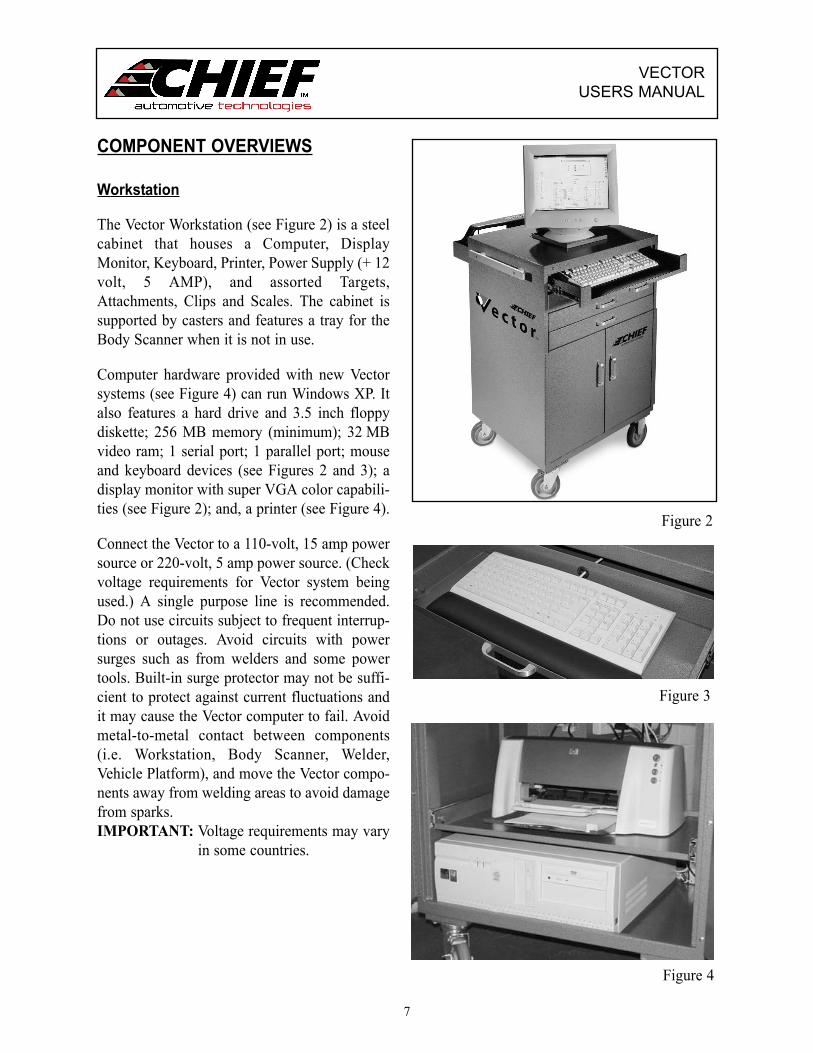
COMPONENT OVERVIEWS
Workstation
The Vector Workstation (see Figure 2) is a steelcabinet that houses a Computer, DisplayMonitor, Keyboard, Printer, Power Supply (+ 12volt, 5 AMP), and assorted Targets,Attachments, Clips and Scales. The cabinet issupported by casters and features a tray for theBody Scanner when it is not in use.
Computer hardware provided with new Vectorsystems (see Figure 4) can run Windows XP. Italso features a hard drive and 3.5 inch floppydiskette; 256 MB memory (minimum); 32 MBvideo ram; 1 serial port; 1 parallel port; mouseand keyboard devices (see Figures 2 and 3); adisplay monitor with super VGA color capabili-ties (see Figure 2); and, a printer (see Figure 4).
Connect the Vector to a 110-volt, 15 amp powersource or 220-volt, 5 amp power source. (Checkvoltage requirements for Vector system beingused.) A single purpose line is recommended.Do not use circuits subject to frequent interrup-tions or outages. Avoid circuits with powersurges such as from welders and some powertools. Built-in surge protector may not be suffi-cient to protect against current fluctuations andit may cause the Vector computer to fail. Avoidmetal-to-metal contact between components(i.e. Workstation, Body Scanner, Welder,Vehicle Platform), and move the Vector compo-nents away from welding areas to avoid damagefrom sparks.IMPORTANT: Voltage requirements may vary
in some countries.
7
Figure 2
Figure 3
Figure 4
VECTOR USERS MANUAL
8
Figure 5
Figure 7
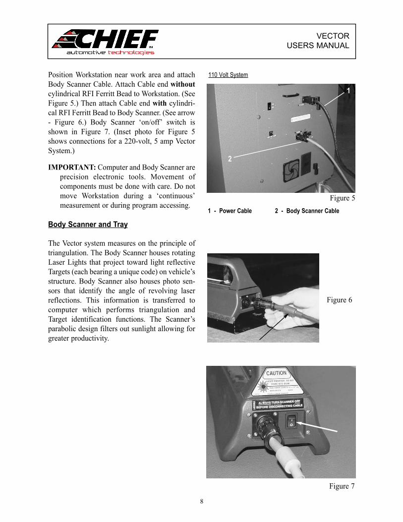
Position Workstation near work area and attachBody Scanner Cable. Attach Cable end withoutcylindrical RFI Ferritt Bead to Workstation. (SeeFigure 5.) Then attach Cable end with cylindri-cal RFI Ferritt Bead to Body Scanner. (See arrow- Figure 6.) Body Scanner ‘on/off’ switch isshown in Figure 7. (Inset photo for Figure 5shows connections for a 220-volt, 5 amp VectorSystem.)
IMPORTANT: Computer and Body Scanner areprecision electronic tools. Movement ofcomponents must be done with care. Do notmove Workstation during a ‘continuous’measurement or during program accessing.
Body Scanner and Tray
The Vector system measures on the principle oftriangulation. The Body Scanner houses rotatingLaser Lights that project toward light reflectiveTargets (each bearing a unique code) on vehicle’sstructure. Body Scanner also houses photo sen-sors that identify the angle of revolving laserreflections. This information is transferred tocomputer which performs triangulation andTarget identification functions. The Scanner’sparabolic design filters out sunlight allowing forgreater productivity.
Figure 6
110 Volt System
1 - Power Cable 2 - Body Scanner Cable
2
1
VECTOR USERS MANUAL
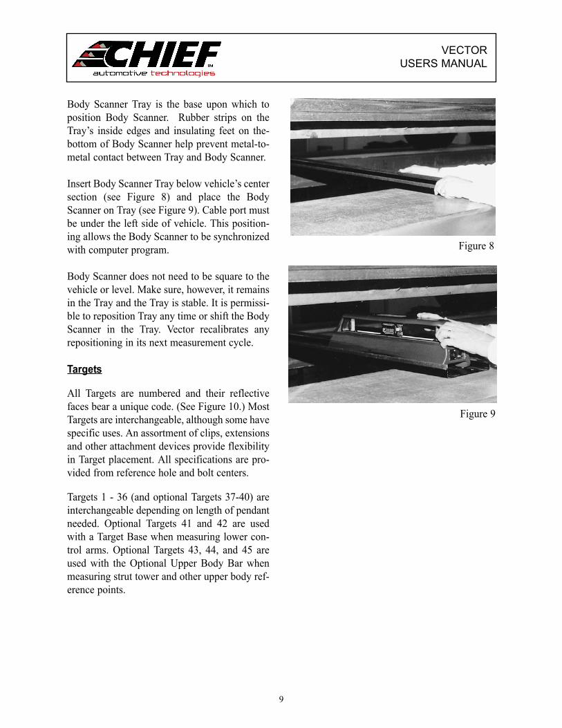
Body Scanner Tray is the base upon which toposition Body Scanner. Rubber strips on theTray’s inside edges and insulating feet on the-bottom of Body Scanner help prevent metal-to-metal contact between Tray and Body Scanner.
Insert Body Scanner Tray below vehicle’s centersection (see Figure 8) and place the BodyScanner on Tray (see Figure 9). Cable port mustbe under the left side of vehicle. This position-ing allows the Body Scanner to be synchronizedwith computer program.
Body Scanner does not need to be square to thevehicle or level. Make sure, however, it remainsin the Tray and the Tray is stable. It is permissi-ble to reposition Tray any time or shift the BodyScanner in the Tray. Vector recalibrates anyrepositioning in its next measurement cycle.
Targets
All Targets are numbered and their reflectivefaces bear a unique code. (See Figure 10.) MostTargets are interchangeable, although some havespecific uses. An assortment of clips, extensionsand other attachment devices provide flexibilityin Target placement. All specifications are pro-vided from reference hole and bolt centers.
Targets 1 - 36 (and optional Targets 37-40) areinterchangeable depending on length of pendantneeded. Optional Targets 41 and 42 are usedwith a Target Base when measuring lower con-trol arms. Optional Targets 43, 44, and 45 areused with the Optional Upper Body Bar whenmeasuring strut tower and other upper body ref-erence points.
9
Figure 8
Figure 9

VECTORUSERS MANUAL
NOTE:1) Although Targets numbered 1 - 36 (and
optional Targets 37-40) are interchangeable,be consistent when placing them at refer-ence points.
2) With the exception of optional Targets 41 -45, Targets can be used on either side of thevehicle. Optional Targets 41 and 42, whichare primarily used to measure ball jointlocations, must be used on the left and rightside of the vehicle respectively. OptionalTargets 43 and 44, which are used to mea-sure strut tower locations, must be installedon the Lower Bar of the Upper Body BarAssembly directly below their respectivePointers. Optional Target 45 must be in thecenter of the Lower Bar.
Target Base
Any Target except optional Targets 43, 44 and45 can be used with the Target Base. (See Figure11.) Target Base sits on platform and Target isprojected upward from it to a reference point.When using Target Base to project a Target to aspecific reference point, the Target Pendantrequires the addition of a Cone Attachment (seeFigure 11) to compensate for absence of anattachment or clip. Optional Targets 41 and 42are used with the Target Base to make compari-son measurements of ball joint locations.
Attachments / Clips
A variety of Attachments, Clips and Extensionsallow Targets to be mounted to practically anyreference hole or bolt. These include BoltAttachments, and Hole Attachments. IMPORTANT: When using different attach
ments than what is suggested in the Point Information Dialog Box, input the correctinformation in the Change AttachmentDialog Box.
10
Figure 10
Figure 11* Cone Attachment
*

VECTOR USERS MANUAL
Bolt Attachments
Bolt attachments work equally well on the bottom ofa structural component or on the side of a structuralcomponent. The nylon base of each attachmentswivels to allow for easy Target adjustments.
Metal Clip Style ‘Bolt Attachments’ have a stronggripping capability and are designed to fit a widerange of bolts (and nuts) used on a vehicle’s struc-ture. The small size grasps bolts/nuts with a 10 to20mm diameter. The medium size grasps bolts/nutswith a 15 to 25mm diameter, and the large sizegrasps bolts/nuts with a 25 to 35mm diameter.(Figure 12 and its inset show an example of a nylonbase bolt attachment.)
Hole Attachments
Hole Attachments snap into all types of referenceholes. Most work equally well on the bottom or side of structural components. The attachments feature a nylonbase or a mounting clip that allows for easy Target adjustments.IMPORTANT: When using Hole Attachments in elon-
gated (oval) reference holes, refer to Point Information Dialog Box for correct positioning.
Aluminum Snap In Attachments - snap into all types of reference holes. They are made of aluminum and are provided in varying sizes ranging from 10 to 32mm in diameter. (Figure 13 and its insets show an example of an aluminum snap-in attachment.)
Bottom Hole Clips - are small metal clips that allow Targets to be mounted to horizontal reference holes measuring 5 to 10mm in diameter. (See Figure 14.)
11
Figure 12
Figure 13
Figure 14

VECTOR USERS MANUAL
Extruded Hole Attachments - mate with both horizon-tal and vertical reference holes. Spring tension holds the attachment within the hole so that Targets can be mounted as shown in Figure 15 and its inset.
Side Hole And Extended Side Hole Clips - are used to mount Targets to vertical reference holes. The looped portion of the attachment hooks inside the reference hole providing the support needed for mounting Targets. (See Figure 16 and its inset.)Extended length side hole clips are provided to help technicians work around obstructions.
Optional Attachments
IMPORTANT: When using different attachmentsthan what is suggested in the Point InformationDialog Box, input the correct information in theChange Attachment Dialog Box.
Optional Magnetic Attachments
Magnetic Attachments (optional) (see Figures 17and 18) are used on bottom of structural memberswhen reference holes or other mounting locationsare not accessible. This attachment, used primarilyfor comparative measurements, should be posi-tioned so that its vertical surface is flush with verti-cal surface of structural member it mounts to. TheTarget can then be mounted in attachment’s clip.
The magnet on the attachment is strong and willmaintain its holding power if cared for properly. AMagnet Keeper (see Figure 18 inset) should be posi-tioned on magnet when the attachment is not in use.IMPORTANT: Never use arc welder or heat near
Magnetic Attachment as this tendsto reduce its holding power.
Figure 15
Figure 16
12
Figure 17
Figure 18

VECTOR USERS MANUAL
Optional Target Extension Rods
Target Extensions (optional) - are available inlengths of 156mm and 256mm. (See Figure 19.) Athird extension is C-shaped for reaching aroundobstructions. The Extensions allow greater flexibili-ty when extra length is needed and when mountingTargets in locations where obstructions prevent nor-mal installation. (See Figures 20 and 21 and Figure20 inset.)
Optional Truck Attachment Package
The Truck Attachment Package (optional) isoccasionally referred to as “Drawer 4”. It consistsof Magnetic Bolt Head Attachments, ThreadedAttachments and extra long Targets. The compo-nents of the package allow the operator to mea-sure the end sections of high ground clearancevehicles.
Magnetic Bolt Head Attachments (optional)- have astrong gripping capability and are designed to fit awide range of bolt heads. (Figure 22 and its insetshow an example of a magnetic bolt head attach-ment.)
Threaded Attachments (optional)- allow operator tothread the attachment onto extruding bolt threads.(Figure 23 and its inset show an example of athreaded attachment.)
Long Targets (optional) - allow operator to mountTargets in the end sections of high ground clearancevehicles. (See Figure 24.) Targets 37, 38, 39 and 40feature longer stems that position the Target’s reflec-tive face on same plane as the body scanner lasers.
1 - 256mm (red)2 - 156mm (blue) 3 - C-Shaped Extension
Figure 19 Figure 20
Figure 21
1 2
3
13
Figure 22
Figure 23
Figure 24

VECTOR USERS MANUAL
Optional Upper Body Bar Assembly
The Upper Body Bar Assembly (optional) con-sists of two horizontal bars joined by a pair ofVertical Scales. (See Figure 25.)
Pointers project from Pointer Housings onUpper Bar to strut tower or other upper bodyreference points. Pointers are provided in ‘cone- shaped’ configurations in lengths of 102mmand 178mm.
Three Targets (Nos. 43, 44, 45) mounted toLower Bar measure height, width (centerline),and length of strut tower or other upper bodyreference points.
In addition to components listed, Bolt Hole Capsand Stud Hole Caps (ranging from 5 to 17mm indiameter) allow the assembly to be mounted toopen bolt holes or studs. (See Figures 26 and27.) The configuration of the cap positions thepointer at center of hole or stud.
14
Bolt Hole Cap Stud Hole Cap
Figure 25
Figure 26
Figure 27

VECTOR USERS MANUAL
Optional Upper Body Bar (continued).........
To install the Upper Body Bar, attach one of theVertical Scales to Upper Bar and place assem-bly’s pointers on reference points. (See Figure28.) Then tighten Pointer Housings (see Figure29); however, if a reference point appears to bemisaligned, do not tighten its Pointer Housing.Next, install Lower Bar (with three Targetsinstalled) and remaining Vertical Scale. If need-ed, adjust height of Lower Bar to enable BodyScanner to view all three Targets.
IMPORTANT:1) Target Number 45 must be in center of Lower
Bar and Target Numbers 43 and 44 must beunder their respective Pointers. (See Figure30.)
2) Body Scanner’s Lasers should strike nearcenter of Target faces.
3) Length of Vertical Scales must be equal, oneside of vehicle to the other.
15
Figure 28
Figure 29
Figure 30

VECTOR USERS MANUAL
Spacers and 3 Inch Bolts
The Vector Measuring System works well withall of Chief’s anchoring systems; however, aslight modification may be required if usingChief’s original Universal Anchoring System.Whenever the anchoring tubes of this systemprevent the mounting of Targets in the rear cor-ners of the vehicle’s center section, operatorsshould offset the clamp bars using the spacersand 3 inch bolts provided. (See Figure 31.) Thespacers and bolts position the rear anchoringstands wider than normal allowing Targets tohang vertically.
Chief Specifications Data
Specifications of domestic and foreign vehiclesare stored in the Vector Computer along withprovisions for periodic updates.
Literature
Literature provided with Vector system includesVector Users Manual, Vector Parts Manual, andVector Assembly Guide. Also included are theusers manuals for the Computer, MicrosoftWindows®; and the Printer.
In addition to this printed literature, the Vectorsystem features an On-Line Help Text and aTutorial (requires optional speakers to listen)that is readily accessible whenever using theprogram. In addition, there is also an On-LineHow To Use Help System. (These Help featuresare addressed in greater detail later in this man-ual.)
16
(Spacers and 3-inch bolts are provid-ed for offsetting clamp bar on someanchoring equipment.)
Spacer
Figure 31

VECTOR USERS MANUAL
Diskettes and CDs
When using diskettes or CDs, handle them cor-rectly. To insert diskette, slide it carefully intothe computer drive slot (label up and slidingdoor first — see Figure 32) until it seats in thedrive. To remove diskette from drive slot, selectEject (from menu options on screen). Graspdiskette at label and slide it from drive slot. Toinsert a CD, open CD Tray, grasp CD by itsedges (see Figure 33) and position CD (label up)in center of tray. Push CD tray into Computeruntil it seats in drive slot. To remove CD, selectEject (from menu options on screen.). Graspedges of CD, and return it to protective case.
Update Diskettes and CDs
The computer provided with the Vector systemcomes fully loaded with operational software,Vehicle Graphics and vehicle specifications.Periodic updates to these are made available asneeded. Updates are sent in CD format. To makeupdates, refer to procedures identified in HelpText and any special instructions mailed with theupdate CD.
Backup Diskettes
Although the computer hard drive stores impor-tant data, it is advisable to store this data onbackup diskettes. (See Figure 34.) Vector opera-tors should maintain a supply of good quality,double-sided, high-density, formatted diskettesand observe the handling rules manufacturerscommonly print on the labels. When makingbackups, label diskettes clearly and carefully asthey are used. To make backups, refer to proce-dures identified in Help Text.
17
Figure 32
Figure 33
Figure 34

VECTOR USERS MANUAL
COMPONENT MAINTENANCE(See also Users Manuals For Computer AndPrinter)
Other than cleaning, factory maintenance byqualified technicians is required for all compo-nents. Be sure system’s power is ‘off’ whilecleaning is performed. In dusty or dirty environ-ments, periodic cleaning is necessary. Specificinstructions for cleaning critical components aredescribed below.
Wipe all parts clean using a lint-free, low-abra-sion cloth using only an ammonia-based glasscleaner. Never use solvents or alcohol-basedcleaners of any kind on any part of the VectorSystem.
Workstation Air Filters
After disconnecting Workstation power source,remove air filters and wash them in warm waterand a mild detergent. Shake off excess water,allow to dry, and reinstall.
Body Scanner Care
Do not plug or unplug cable from Body Scannerunless it is turned off.
18
Keep Body Scanner away from areas being under-coated, primed or painted. Keep heat away fromBody Scanner when using a torch for thermalstress relieving of structural components.
Clean all Body Scanner parts with a lint-free, low-abrasion cloth and a good quality glass or ammoniacleaner. Never use solvents or alcohol-based clean-ers on Body Scanner glass.
Care of Targets
Keep Targets away from areas being undercoated,primed or painted, and away from heat when usinga torch for thermal stress relieving of structuralcomponents.
Use a lint-free, low-abrasion cloth and a goodquality glass or ammonia cleaner to clean Targets.Do not use solvents.
Avoid scratching or gouging the Target’s reflec-tive surface.
VECTOR USERS MANUAL
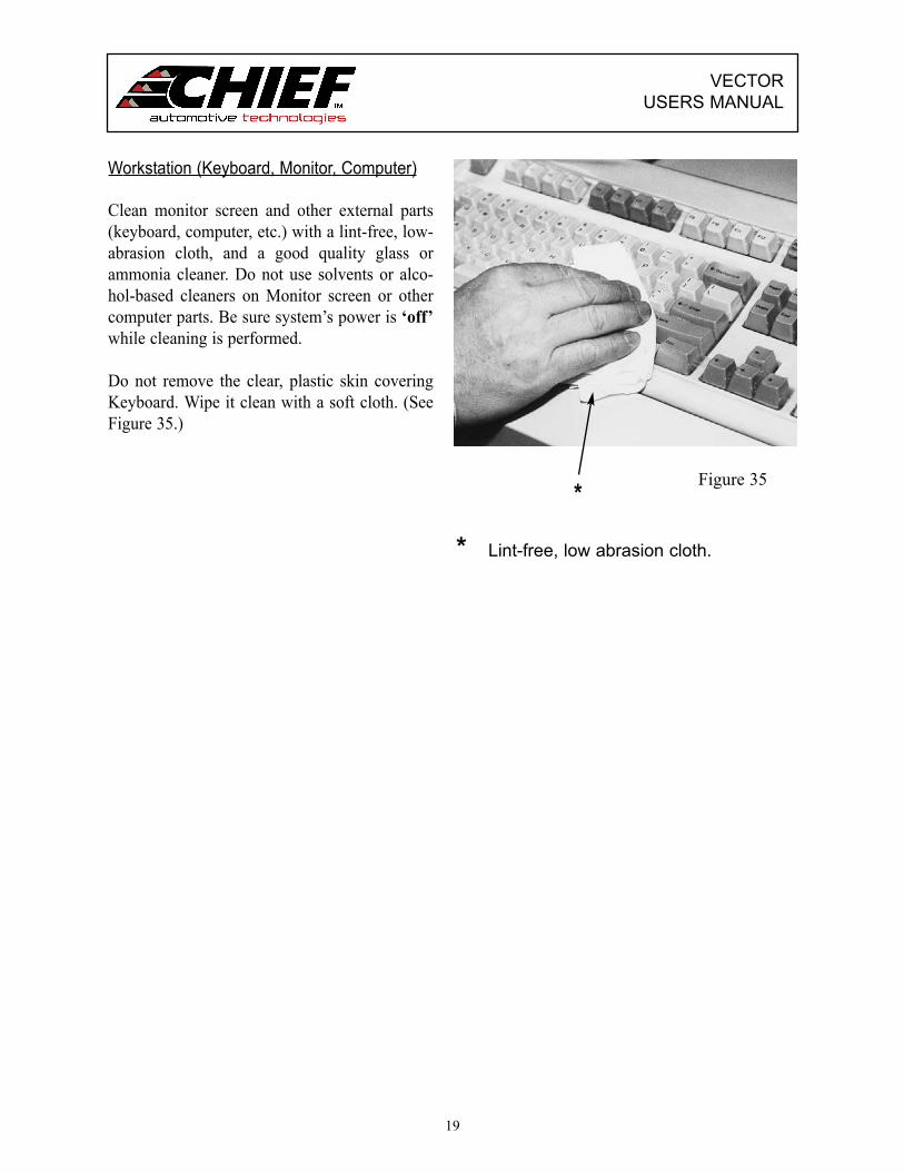
Workstation (Keyboard, Monitor, Computer)
Clean monitor screen and other external parts(keyboard, computer, etc.) with a lint-free, low-abrasion cloth, and a good quality glass orammonia cleaner. Do not use solvents or alco-hol-based cleaners on Monitor screen or othercomputer parts. Be sure system’s power is ‘off’while cleaning is performed.
Do not remove the clear, plastic skin coveringKeyboard. Wipe it clean with a soft cloth. (SeeFigure 35.)
19
* Lint-free, low abrasion cloth.
Figure 35*

VECTOR USERS MANUAL
COMPONENT TROUBLESHOOTING
The Vector computerized measuring systemcontains on-line troubleshooting assistancedesigned to identify and eliminate problems thatarise when using the system. In most instances,troubleshooting problems are signaled by “ErrorMessages” that appear on screen. The VectorHelp Text contains information and possiblesolutions for these “Error Messages”.
There are two methods of accessing trou-bleshooting assistance.
• Press F1 Key on Keyboard when “ErrorMessage” appears. This method accesses aspecific Help Page immediately.
• Access Help Index by Menu selection or ToolBar Icon. Then select Troubleshooting toaccess a specific menu. Each selection madein this process channels the operator to thehelp that’s desired.
Although “Error Messages” identify problemswhen the Vector system is running, they obvi-ously cannot identify problems when the systemis down. The following suggestions are provid-ed when the system’s major components are notfunctioning. In addition to information listedhere and in the Vector Help Text, refer also toUser’s Manuals for the Computer and Printer. Iftroubleshooting problem(s) can not be solvedafter reviewing these sources of information,contact Chief Automotive Technologies forassistance. (See Page 5 for instructions.)
20
No Power To System Components
Computer, Monitor, Keyboard, Mouse, BodyScanner, Printer
• Make sure the Vector system is connected to alive power source. (Dependent upon modelused, power source might be 110-volt, 15 ampor 220-volt, 5 amp.) A single purpose line forthe Vector is recommended. Do not use circuitssubject to frequent interruptions or outages.Also, avoid circuits with power surges, such asfrom welders and some power tools.IMPORTANT: Voltage requirements may vary
in some countries.
• Check all electrical and cable connections (i.e.power source, back of Workstation, insideWorkstation, back of Computer, back of Printer,end of Body Scanner).
• Check fuses on back of Workstation and replaceif blown.
• Inspect all electrical wiring and cable for dam-age or wear.
• Make sure ‘on’/’off’ switches are in ‘on’ posi-tion (Computer, Body Scanner, Printer).

VECTOR USERS MANUAL
III. VECTOR PROGRAM
STARTING UP VECTOR SYSTEM
Turn system power switch ‘on’. (Figure 36shows switch at rear of workstation.)
Computer will examine its circuits and prepareto run the Vector system. This process is called‘booting up the computer’. It takes several sec-onds to complete.
When the Vector ‘Title Screen’ (opening win-dow) is displayed (see Figure 37), the ‘bootingup’ procedure is complete.
NOTE: On computer systems runningWindows XP, Windows 2000,Windows NT 4.0 or higher, theVectorTitle Screen will appear asshown in Figure 37.
21
Figure 37
Figure 36
1 Select a Task 3 Finish Measurement2 Start New Measurement 4 Reacall Measurement
2
1
3
4

VECTOR USERS MANUAL
VECTOR TITLE SCREEN — OPENING WINDOW
The Vector Title Screen allows the operator toeither Start New Measurement, FinishMeasurement, or Recall SavedMeasurement.
When selecting “Start New Measurement”,Dialog Boxes appear allowing the operator toquickly identify the year, make, model andbody style of the vehicle to be measured. Inregard to the input of customer and/or workorder information this can be entered at thesame time vehicle is selected (“advanced”mode) or when the first measurement is saved(“basic” mode). See Preferences — “UserOptions” below.
When selecting “Finish Measurement”, aDialog Box allows the operator to select thedesired vehicle from a list of vehicles thathave not yet been finished.
Figure 38
22
When selecting “Recall Saved Measurement”,a Dialog Box allows the operator to search forthe vehicle by customer name, vehicle descrip-tion or work order number.
PREFERENCES
The Vector Title Screen also allows operators toaccess the system’s Preferences Dialog Box.(See Figure 38.) Tabs within this box allow oper-ators to tailor the program to suit their individualneeds. Through the User Options, Vector Setup,Printer / Reports, Network Setup and QuickEntry Setup “Tabs”, operators may select, forexample, the ‘basic’ or ‘advanced’ mode ofoperation, the items they want to appear onprinted reports, identify computer links, ‘acti-vate’ or ‘deactivate’ tools and determine certain‘default’ settings.
1 2 3 4 5 6
1 General Preferences / Options 3 Vector Setup 5 Network Setup
2 User Options 4 Printer / Reports 6 Quick Entry Setup

VECTOR USERS MANUAL
Vehicle OptionsFileUpdateBack UpRestoreExit
Figure 39
VECTOR WINDOWS ANDMENUS
The Vector software features five operationalWindows. These include: Title Screen —Opening Window; Initial Inspection — BaseReference Entry; Repair; Final Inspection;and, Recall. Each Window features a MenuBar that identifies operations or commandsthat are specific for that Window. See expla-nation of Windows and an example on pages24 and 25. (See also Vector Help Text andTutorial. Optional speakers required to listento Tutorial.
Menu selections appearing below the Menu Barheadings identify tasks the system is ready toperform. To make selections, operators have theoption of using either the Keyboard or Mousedevices or a combination of the two. (Specificinformation on using the devices is covered onPages 30 through 32 of this manual and in theVector Help Text.) Menu selections that appeardimmed are inaccessible.NOTE: Tool Bar Icons (Buttons) provide a
faster way to perform tasks than themenu selection method. (See Tool BarIcons / Buttons in Vector Help Text.)
23
The selection of menu items or tool bar itemsoften prompt the appearance of Dialog Boxeson Screen. Dialog Boxes allow operators to sup-ply additional information to complete a task.Some Dialog Boxes require a selection from alist of options whereas others require theinputting (typing) of information. See explana-tion of dialog Boxes and examples on pages 26and 27. (See also Vector Help Text.)
IMPORTANT:Refer to Help Text for a more detailed descrip-tion of menu selections. Tool Bar Icons(Buttons) and related procedural information.For information on how to use Help, see Pages37-39 or access the How To Use Help System.Refer also to User’s Guide for MicrosoftWindows.
SHUTTING DOWN VECTOR SYSTEM
To shut down the Vector System, first save all nec-essary information if needed. Then select Exitfrom list of items under File heading in menu. (SeeFigure 39.) Then access Start Menu List, selectShut Down and turn off power switch at rear ofWorkstation.

VECTOR USERS MANUAL
WINDOWS
The Vector program is provided in a Windowssoftware format that allows operators to managework easily and efficiently. All work applica-tions appear on Windows which are basicallylarge rectangular areas on screen. MostWindows have certain elements in common, forexample: Title Bar, Menu Bar, etc. Not allWindows, however, have every element.
In addition to elements that appear on a Window,there are other elements that appear along theright side or bottom edge of Window. Such ele-ments vary from one Window to another.
Figure 40 (see next page) identifies some of thebasic elements that appear either directly onWindows or at the right side or bottom edge ofWindows. Elements identified on the illustrationare described below. The illustration displayed isrepresentative of an Initial Inspection Window(Base Reference Entry).
To work within a Window, operators have theop-tion of using the Keyboard or Mouse or a com-bination of the two. Specific information onusing these devices appears on Pages 30 through32 and in Vector on-line Help Text.
Title Bar - Identifies Window. (Located acrosstop of Window.)
Menu Bar - Identifies Menu Headings.(Located across top of page belowTitle Bar.)
24
Menu Headings - Identifies menu lists that areavailable.
Menu List - Identifies tasks computer is ready toperform.
Scroll Bars - Used to expand Window whenenlarged image of Vehicle Graphic exceeds display area.
Tool Bar Icons (Buttons) - Used to perform cer-tain functions quickly. Graphic suggests purpose or identity of function.
Status Bar - Systematically appears at bottom ofWindow to provide on-screen helpthroughout the Vector Program. Brief messageseither instruct the operator as to next course ofaction or describe purpose of menuselections or Tool Bar Icons.
Dialog Box - Box that appears on Window forinputting, viewing or editing information.
Vehicle Graphic - Top view of vehicle’s sub-structure showing reference point locations, vehi-cle measurement, and direction of misalignment.(See additional information on Vehicle Graphicson Pages 28-29.)
Wizard - On screen messages designed to guide the operator through software procedures. Eachmessage allows the accessing of more informa-tion, including photos and videos in some cases,or advancement to the next step.

11Figure 40
25
WINDOW EXAMPLE
VECTOR USERS MANUAL
Vector - Initial Inspection (Base Reference Entry) Chevrolet Cavalier
2 34
98
1
Edit Display Help
Change AttachmentDelete Base TargetDelete All Base TargetsMechanicsMeasureCancel
5
6
10
7
1 Menu Bar 7 Menu Headings2 Title Bar 8 Status Bar3 Point Information 9 Vehicle Graphic
Dialog Box (specifications mode)4 Scanner View Dialog Box 10 Wizard ‘On’ / ‘Off’ 5 Menu List 11 Tool Bar Icons
Turn the Wizard On or Off
VECTOR USERS MANUAL
DIALOG BOXES
Dialog Boxes appear on a Window when opera-tor must supply additional information to com-plete a task or when operator needs to accessinformation. Most Dialog Boxes require selec-tion of options, whereas others require inputting(typing) of information. Most Dialog Boxeshave elements in common, for example: TitleBars, Command Buttons, and Control-MenuSymbol Button. Not all Dialog Boxes haveevery element.
Figures 41-43 identify some of the differentstyles of Dialog Boxes and some of the differentelements within Dialog Boxes. Figure 41 (seepage 27) shows a Customer Data Entry DialogBox; Figure 42 shows a Scanner View DialogBox; and Figure 43 shows a Point InformationDialog Box. Elements that appear in theseDialog Boxes are described below. To workwithin or move a Dialog Box, operators may usethe Keyboard or Mouse device or a combinationthe two. Specific information on the use of thesedevices within Dialog Boxes appears on Pages30-32 and in Vector on-line Help Text.
Title Bar - Identifies Dialog Box. (Locatedacross top of Dialog Box.)
Command Button - Used to perform certainfunctions quickly. Graphic suggests purpose oridentity of function.
26
Field - Specific line for inputting, viewing, editinginformation.
Cursor - Operator controlled indicator thatappears on Windows, Dialog Boxes, and HelpPages. Changes shape as per application.
List Box - Listing of choices that are available.
Close Button - Used to remove Dialog Box fromWindow. (Located in upper right corner of DialogBox.)
Scroll Bars - Used to expand List Box when infor-mation exceeds display area.
Target Numbers - Numbers in Scanner ViewDialog Box represent Targets mounted to vehicleand are displayed as per their positioning relative to the Body Scanner.
Cone (Scanner View) - Identifies Target(s) not seenby the Body Scanner.
Body Scanner - Graphic in Scanner View DialogBox represents Body Scanner. Laser Hubs areidentified as Hub 1 (on left side of vehicle) and Hub 2 (on right side of vehicle.)
Radio Button - Diamond-shaped indicator onDialog Boxes that identifies component in use orcomponent that is suggested.
Control-Menu Symbol - Accesses Menu List forRestore, Move, Size, Minimize, Maximize andClose Functions.

VECTOR USERS MANUAL
27
5
1 43
26 8
2
1
17
12
14
Hub 1 Can’t See Target: 18
15 16
9 1311
Figure 41
Figure 42 Figure 43
10 10
7
DIALOG BOX EXAMPLES
1 Title Bar2 Command Button3 Field4 Down Arrow (accesses
list box with scroll bars.)
5 Customer, Vehicle, WorkOrder Information Sections
6 Customer, Vehicle, WorkOrder Tree
7 Scroll Bar
8 Erase Button9 Body Scanner Hub10 Control-Menu Symbol11 Minimize, Maximize, Close12 Radio Button Indicator
13 Close Button14 Cone15 Target Number16 Error Message17 Camera Icon (photo available)

VECTOR USERS MANUAL
VEHICLE GRAPHICS
Vehicle Graphics are top view drawings of avehicle’s structural components. In the Vectorprogram, they appear on all Vector Windows.Vehicle Graphics match make, model, and yearof vehicle identified in the Vehicle InformationDialog Box. Although each Graphic shows gen-eral shape and location of reference points, pro-gram’s Zoom feature allows operator a closer,more detailed look.
Vector measurements are displayed on VehicleGraphics. (See Figure 44.)
Datum Height Measurements appear in boxesacross the top of Vehicle Graphic with top num-bers representing the right side of vehicle andbottom numbers representing the left side.
28
* Body Zero Line/Plane width measurements appear inside solid box.
R
L
RL
R (right)L (left)
Height
Length
Centerline Width Measurements appear direct-ly on Vehicle Graphic with numbers above center-line representing the right side of vehicle andnumbers below centerline representing the leftside.
Datum Length Measurements appear along thehorizontal line at the bottom of Vehicle Graphicwith numbers above the line representing the rightside of vehicle and numbers below the line repre-senting the left side. Datum length measurementsoriginate at the Body Zero Line/Plane which canbe established at front or rear of vehicle’s centersection. This line/plane is identified by its widthmeasurements that appear inside a solid box.NOTE: Indicator lines link reference points on
Vehicle Graphic to their respective mea-surements.
*
(right)
(left)
(right)(left)
Figure 44

VECTOR USERS MANUAL
Measurements can be displayed in three differ-ent modes: Arrow, Actual Measurements andSpecifications.
Arrow mode shows direction and amount ofmisalignment for each reference point measured.(See Figure 45.) Arrows indicate direction ofmisalignment and numerical references indicateamount of misalignment . . . difference betweenactual measurement and vehicle specification.Whenever amount of misalignment exceedsallowable tolerance, arrow and numerical refer-ence are shown in ‘red’. When it is within allow-able tolerance, they appear in ‘blue’.
Actual Measurements mode shows only cur-rent measurements taken by Vector. (See Figure44 - previous page.) When specifications don’t
29
R
L
RL
RL
Height
LengthFigure 45
exist in the Vector data base, this mode can be used to repair structure through comparisonmeasurements.
Specifications mode shows only a vehicle’spublished specifications as obtained from theVector Data Base. It is for reference purposesonly.
Target Graphics and/or Target Numbers appearon the Vehicle Graphic in certain situations. Forexample: When entering Base ReferenceTargets, or when selecting Make Point, MoveTarget, Freeze or Thaw options. The appearanceof such Targets on the Vehicle Graphic allowsoperator to work with Targets as per the appli-cation.
(right)(left)
(right)
(left)
(right)(left)

KEYBOARD AND MOUSE
The Keyboard and Mouse are used to operate thecomputer program. (See Figures 46 and 47.) Thesystem can be operated using either device or acombination of the two. The most efficientmethod of operation is to use the Mouse in com-bination with the Keyboard. The following infor-mation addresses each device individually pro-viding specific information pertinent to its usewith the Vector program.
KEYBOARD
The following Keyboard procedures relate tospecific Vector applications. For information oncommon Keyboard operations (i.e. typing text,editing text, etc.), refer to Special Keys Sectionof this manual (see Pages 31-32) and readUser’s Guide For Microsoft Windows.
Menus
To select Menu Bar headings on Windows, usea two key combination. Press and hold downone of the Alt Keys and then press underlinedletter in heading. For example: Combination Alt+ F accesses File heading. To select a menuitem below heading, press only underlined letterof the item’s name. Then press Enter Key.NOTE: Menu items below headings can also beselected using Arrow Keys and Enter Key.
Vehicle Graphic
To move Cursor around Vehicle Graphic whenentering Base Reference Point Targets, useArrow Keys.
VECTOR USERS MANUAL
30
Dialog Box
NOTE: The following does not apply toMechanics Dialog Box which requires use ofMouse device.
To work within a Dialog Box:
1. Press Tab Key to access appropriate Fields,Command Buttons, or Control-Menu Symbol.To back track, hold Shift Key down and pressTab Key.
2. Type information in appropriate Fields or scrollfor it when List Boxes appear. Arrow Keysscroll one item at a time and Page Up and PageDown Keys scroll one group of items at a time.
3. Select appropriate Command Button and pressEnter Key.
Figure 46

VECTOR USERS MANUAL
4. In some Dialog Boxes, move indicators usinga two key combination. Press and hold one ofthe Alt Keys and then press underlined letterof the selection.
IMPORTANT: When working in a DialogBox, DO NOT press Enter Key until perti-nent information has been inputted andappropriate Command Button has beenselected. The only exception to this pertainsto Shop Information Dialog Box where it isnecessary to use Enter Key during inputtingprocess.
To “Move”, “Close”, And / Or “Activate”
1. To move a Dialog Box using Keyboard, pressAlt + Space Bar. Then select Move frommenu and press Enter Key. Use Arrow Keysto move Dialog Box to appropriate locationand then press Enter Key again.
2. To close a Dialog Box using Keyboard, accessControl-Menu Symbol (upper left corner) andpress Enter Key. Then use Arrow Keys toselect Close and press Enter Key again.
3. When two Dialog Boxes are displayed at sametime, only one will be activated. To activatethe other, press Alt + F6 Key. Title Bar ofactivated Dialog Box will appear highlighted.
31
To Access “Vector Help Pages”
1. To access Help Index, press F1 Key uponaccessing a Vector Window or select Indexfrom list of items under Help heading in anyMenu Bar.
2. To access specific Help about information dis-played (i.e. highlighted Menu items, DialogBoxes, Vehicle Graphics, Status BarMessages, Error Messages, etc.), press F1Key.
NOTE: In regard to Dialog Boxes, specific Helpcan also be accessed by selecting Help icon which appears in most Dialog Boxes.
To Access “How To Use Help”
To access How To Use Help, first access anyVector Help Page. Then press F1 Key or selectHow To Use Help from list of items under Helpheading in Menu Bar.
To Access “Tutorial”
To access Tutorial, access Help Index and selectVector Tutorial. (See Video Camera Icon.)Optional speakers required to listen to Tutorial.

VECTOR USERS MANUAL
To Access “How To Use Help”
To access How To Use Help, select How To UseHelp from list of items below Help heading at topof any Help Page.
To Access “Tutorial”
To access Tutorial, first select Index from list ofitems under Help heading or select Help iconin Tool Bar at right side of screen. Then selectVector Tutorial. (See Video Camera Icon.)Optional speakers required to listen to Tutorial.
To Access “Wizard”
To access the “Wizard” on-screen help messages(Initial Inspection — Base Reference Windowonly), select the “Guide Me” button in lowerright corner of screen.
32
Figure 47 To operate the Mouse (see Figure 47), move itacross the pad. This action positions the Cursorat desired menu item or Tool Bar Icon (Button)on Window or to desired Field or Command Button in Dialog Box. Toselect (activate) the item chosen, press andrelease (click) left side button on Mouse. Alsouse clicking method to activate Scroll Bars andmake selections from List Boxes.
Dialog Box
1. To move Dialog Box, move Cursor to TitleBar and then press and hold left-side buttonon Mouse while dragging Dialog Box todesired location. Then release.
2. To remove Dialog Box from Window, moveCursor to Control-Menu Symbol (upper leftcorner). Upon accessing List Box, selectClose option.
3. When two Dialog Boxes are displayed at sametime, select non-active Dialog Box by posi-tioning cursor on that box and pressing andreleasing (clicking). Title Bar of activatedDialog Box will appear highlighted.
To Access “Vector Help Pages”
1. To access Help Index, select Index from list ofitems under Help heading or select Help iconin Tool Bar at right side of screen.
2. To access Help page that relates to a specificDialog Box, select Help icon which appearswithin the Dialog Box.
MOUSE

VECTOR USERS MANUAL
F2 — Function Key to save measurements.
F5 — Function Key to measure one time.
F6 — Function Key to start or stop continuousmeasuring.
Home Key — Moves Cursor to beginning of field.
Insert Key — Inserts text without erasing othertext.
Num Lock Key — On/Off Key for cluster of num-ber keys on lower right side of Keyboard.
Number Keys — Two sets of Number Keys avail-able on Keyboard.
Page Down Key — Used for scrolling downwardthrough page when text extends beyond Window.
Page Up Key — Used for scrolling upwardthrough page when text extends beyond Window.
Print Screen Key — Command Key for print-ing current Vector Window.
Shift Key — Serves same function as typewritershift key.
Tab Key — Used to move around in Help and inDialog Box.
Typewriter Keys — Same as typewriter.
33
SPECIAL KEYS
As previously indicated, the Vector program canbe operated using the Keyboard or Mouse or acombination of the two.
When using Keyboard either solely or in combi-nation with the Mouse, operators will use notonly the ‘letter’ and ‘number’ keys, but the spe-
Alt (alternate key) — Two key combinationinvolving Alt Key + another key.
Arrow Keys — Used to move Cursor up or downand right or left, also moves highlighted Cursor insome applications.
Backspace Key — Moves Cursor backwards toerase last character.
Control Key — Two key combination involvingCtrl Key + another key.
Delete Key — Removes one character to right ofCursor or all highlighted areas.
End Key — Moves Cursor to end of field.
Enter Key — Used in Keyboard operation only.Used to select items from menus, close DialogBoxes, access other Dialog Boxes, enter Targets onVehicle Graphic, select Command Buttons, disposeof Help Pop-ups. Serves same function as Mouse but-ton.
Escape Key — Used in Keyboard operation only.Used to back up within Menus and serves same func-tion as Command Button on Dialog Boxes.
Function Keys — Keys marked F1, F2, F5 and F6are Special Keys that perform special functions.
F1 — Function Key for Help.
cialty keys as well. Many of these keys providea more convenient method for moving around inWindows, Dialog Boxes and Help Pages.
Following is a listing of special keys that areused in the Vector Program.
X Cancel

VECTOR USERS MANUAL
34
3
2
VectorHelp System
Figure 48
4
1
1 Control-Menu Symbol 3 Help Pop-Up
2 Help Page 4 Minimize, Maximize, Close Buttons
HELP TEXT
The On-Line Help Text provides assistance onpractically all aspects of Vector computerizedmeasuring system. Information ranges frominstallation of hardware components to softwareutilization.
The Help Text provides all the information need-ed to run the Vector Program. Information is pre-sented in form of Help Pages that providedetailed information on a given subject or HelpPop-Ups which provide concise definitions ofimportant terms or phrases. (See Example —Figure 48.)
The Vector Help Text can be accessed in a vari-ety of ways and is available any time the systemis up and running. Operators have flexibility ofjumping to specific Help Pages or Pop-Ups, orthey can access Index Pages if needing to searchfor a topic. The following information outlinesvarious ways to access Help Text. For informa-tion on using Help Pages, refer to How To UseHelp section of this manual or access on-lineHow To Use Help System. An additional sourceof information is User’s Guide for MicrosoftWindows®.

VECTOR USERS MANUAL
35
23
1
Figure 49
1 Vector Tutorial Icon 2 Title Bar 3 Minimize, Maximize, Close Buttons
To Access Specific Help From Window OrDialog Box
IMPORTANT: See Keyboard and Mouse onPages 30 - 32 for information on moving around(and making selections) in Windows and DialogBoxes. See How To Use Help on Pages 36-38 forinformation on obtaining additional help afteraccessing a Help Page.• Highlight specific menu item and press F1
Key.• Select (Command Button) in active
Dialog Box or press F1 Key when activeDialog Box appears on Window.
• When there are no active Dialog Boxes onWindow, press F1 Key to access definitionsfor that Window’s Menus and Tool Bar Icons.The lone exception is when Title Bar ofWindow indicates Base Reference Entry. The F1 Key then accesses Base Reference Entryprocedures. From this procedures page, oper-ator has option to access definitionsfor Base Reference Entry Menus and Tool Bar
Icons.NOTE:
1. Dialog Boxes are active when Title Bars arehighlighted.
2. When an active Dialog Box appears, removeit from Window prior to pressing F1 Key.
• To access Help Index, select Index from list ofitems under Help heading or select (HelpIcon) from Tool Bar.
NOTE: Upon accessing Help Index (seeFigure 49), operator can select one of sever-al categories listed. Selection of that catego-ry will access a more specific menu. Eachselection made in this process channelsoperator to help that’s desired. Camera Iconat top of Help Index page accesses theVector Tutorial. (Optional speakers requiredto listen to Tutorial.)
?? Help

VECTOR USERS MANUAL
36
used for Initial and Final Inspections , allowle damage. When using Freeze Option, Reference Point Target and then removeval of the Target allows Vectorto measuom the Body Scanner.
used for Initial and Final Inspections, allowle damage. When using Freeze Option, oReference Point Target and moveval of the Target allows Genes measuom the Body Scanner.
HOW TO USE HELP
NOTE: In addition to the following informationon How To Use Help, refer to on-lineHow To Use Help System and User’sGuide for Microsoft Windows®.
Upon accessing a specific Help Page or IndexPage, operators can easily move throughout HelpText to access additional information as needed.As noted in Help Text information on Pages 34-35 , the basic way to do this is by jumping fromone Help Page to another Help Page or to a HelpPop-Up.
Throughout the Help Text, key words or phrasesare highlighted in ‘Green’. When selected, thesekey words or phrases serve as stepping stonesthat access Help Pages or Pop-Ups that relatespecifically to the key words or phrases. If wordis underscored with solid line, the jump goes to aHelp Page; and, if word is underscored with adotted line, the jump goes to a Help Pop-Up.(See Figure 50.)
The method of selecting key words or phrasesIcons) on Help Pages varies dependent upon useof Keyboard or Mouse. If using Keyboard, useTab Key to advance forward from one key word
or phrase (or Icon) to the next. Use Shift + TabKey to move back. Upon reaching desired keyword or phrase (or Icon), press Enter Key. Ifusing the Mouse, position Cursor on Key word orphrase (or Icon) . . . Cursor changes to shape ofhand when correctly positioned. (See Figure 51.)Then select word or phrase (or Icon) by pressingand releasing (clicking) left side button onMouse.
Help Pages and Pop-Ups often feature illustra-tions and/or photos which help clarify proceduresor identify the Vector components. Illustrationsappear directly on respective Help Pages andPop-Ups. Photos do not appear directly on HelpPages and Pop-Ups; however, their availability isindicated by (Camera Icons). To access pho-tos, select Camera Icon in same fashion as select-ing a key word or phrase.
To remove Help Pages from Window, selectClose Button in upper right corner of Help Page.To remove a Help Pop-Up or a photo from theWindow, press any letter key on keyboard orposition Cursor on Window and press and releaseleft side button on Mouse.
Figure 50 Figure 51

VECTOR USERS MANUAL
37
4
56
7
3
Figure 52
1
2
1 Control Menu Symbol 4 Vector Help System Title Bar(accesses Minimize, Maximize, Close options) 5 Menu Bar
2 Accesses Tutorial Demo (require s optional speakers to listen) 6 Command Buttons3 Help Page Title 7 Scroll Bars
Using the Mouse, position Cursor at vertical orhorizontal border or at corner of Help Page . . .Cursor will change to shape of double arrow.Press and hold down left side button on Mouse.Drag Cursor to enlarge or reduce Help Page andthen release.
Using Keyboard, press Alt + Space Bar to accessmenu list below Control-Menu Symbol at leftside of Title Bar. Using Arrow Keys, select Sizeand press Enter Key. Move Cursor (using ArrowKeys) to vertical or horizontal border or to cornerof Help Page. Continue using Arrow Keys to sizethe Help Page. When sized correctly, press EnterKey.
Help Page Features
Each Help Page in the Vector Help Text has cer-tain elements in common. These include a MenuBar, Command Buttons, Scroll Bars, Minimizeand Maximize options and a Close option. (SeeExample — Figure 52.) Scroll Bars exist onsome of pages.
Menu Bar allows operators to access File, Edit,Bookmark, Options and Help Functions.Command Buttons allow operator to accessinformation quickly. Minimize and Maximizefeatures enlarge and reduce Help Page and Closeoption removes it from Window. Scroll Barsallow access to information that does not fit onWindow.Minimize and Maximize options allowonly limited sizing of Help Page.

VECTOR USERS MANUAL
38
Figure 532
1
1 Control-Menu Symbol 2 Control Menu
Help Page Command Buttons
Command Button accesses theVector Help Index.
Command Button accessesDialog Box that allows operatorto do an alphabetical search fordesired Help Topic.
Command Button allows opera-tor to return to previously dis-played Help Page.
Command Button accessesDialog Box that allows operatorto print the Vector Help page dis-played.
NOTE: When accessing on-line How To Use Help System, a CommandButton appears with
and Command Buttons. Selection of the
Button accesses a listing ofcommon terms used in WindowsProgram. Selection of a term from list-
Contents
Search
Back
Glossary
ContentsSearch Back Print
Glossary
ing accesses its definition. To access on-line How To Use Help System, firstaccess a Vector Help Page and do oneof the following: Select How To UseHelp from list of items under Helpheading; or, press F1 Key.
Control-Menu Symbol
List of items under Control-Menu Symbol (seeFigure 53) allows operator to restore Help Pageto normal size; move Help Page to another loca-tion on Window; enlarge or reduce size of HelpPage; close Help Page and return to VectorProgram; or, switch to another active computerprogram.
NOTE: To access this menu, position Cursor onControl-Menu Symbol and press andrelease (click) left side button onMouse. Using Keyboard, press Alt +Space Bar.

VECTOR USERS MANUAL
VECTOR TUTORIAL
NOTE: Optional speakers are required to lis-ten to the tutorial.
The Vector Tutorial covers the basic featuresof the Vector system. The program is designedfor both first time users and for techniciansneeding to review the basic fundamentals ofmeasuring. The Tutorial not only helps techni-cians navigate through the system software butalso covers basic measuring concepts andprinciples.
The Tutorial features narrated text that is com-plemented by detailed illustrations, photos andvideos. The Tutorial is installed on the harddrive of all new Vector Systems and is alsoavailable in CD format.
The Tutorial may be accessed in two ways:from Help Index (Contents) page (click VideoCamera Icon); and, from Start Menu List(click Vector Electronic Measuring and selectVector Tutorial).
Many of the videos contained in the Tutorialare also accessible from related Help Textpages. Clicking the Camera Icon (see Figure54) on these pages accesses the video.
VECTOR HELP WIZARD
The Vector Help Wizard (available on neweroperating systems) is an on-screen guide thatassists the technician during the initial inspec-tion process. (See Figure 55.) Following theend of each Step, the technician may advancethe Wizard to the next Step or seek additionalinformation relating to the Step at hand.
The additional information may appear asadditional text, a video presentation or a stillphoto or illustration. The Wizard messagesare accessible via the Guide Me icon located atthe bottom right hand corner of the screen.(See Figure 56.)
Figure 54
Figure 55
Figure 56
39
*
* Camera Icon(requires optional speakersto listen)
*
* Help Wizard (On Screen Guide)

Chief Automotive Technologies996 Industrial DriveMadison, IN 47250Phone: 800-445-9262Fax: 866-275-0173 www.chiefautomotive.com
Chief reserves the right to alter product specificationsand/or package components without notice.