vector control of squirrel cage induction generator for ...€¦ · vector control of squirrel cage...
TRANSCRIPT

Vector Control of Squirrel Cage InductionGenerator for Wind Power
Jose Luis Domınguez-Garcıa∗, Oriol Gomis-Bellmunt∗†, Lluıs Trilla-Romero∗ and Adria Junyent-Ferre†
Abstract—The paper deals with squirrel cage induction gener-ator connected to the grid through a back-to-back converter,which is driven by vector control. The stator side convertercontrols the generator torque using an indirect vector control.The grid side converter controls the DC Bus voltage and thereactive power. The proposed control strategy is validated bysimulation in Matlab/Simulinkr.
Index Terms—Back-to-back converter, squirrel cage inductiongenerator (SCIG), vector control, wind power generation.
NOMENCLATURESymbols Superscripts
λ Flux linkage ∗ Set pointΓ Torque e synchronism referenceθ Angle Subscriptθ Angular velocity s stators slip l grid-side converterr Resistance z gridL Inductance d d-axisM Mutual inductance q q-axis
I. INTRODUCTION
W IND Power is one of the most promising renewableenergy sources after the progress undergone during
the last decades. In this field, SCIG has been used, specially,as a fixed-speed generator or for micro-generation [1], [2].SCIG control can be done using different approaches: scalaror vector control, direct or indirect field orientation, rotor orstator field orientation [3]–[5], each one have advantages anddisadvantages, for example, scalar control [6]is quite simple toimplement but easily unstable, a better performance is directvector control, which needs estimated and sensed flux valuesto define and control the field orientation references, but itis necessary to use hall-effect sensors, which is problematic,and expensive, in practise [7], [8].It has been chosen an indirect field-orientation method, whichis more sensitive to knowledge of the machine parameters,but it frees from the use of direct sensing [9], [10].This paper proposes an indirect vector control strategy , withthe voltages referred to a q-d synchronous frame aligned withthe rotor flux vector, for the stator-side converter.
∗ Catalonia Institute for Energy Research (IREC), Electrical EngineeringArea, C Josep Pla, 2, edifici B2, Planta Baixa - 08019 Barcelona, Spain (email:[email protected], [email protected], [email protected])† Centre d’Innovacio Tecnologica en Convertidors Estatics i Acciona-
ments (CITCEA-UPC), Departament d’Enginyeria Electrica, UniversitatPolitecnica de Catalunya, ETS d’Enginyeria Industrial de Barcelona, andEU d’Enginyeria Tecnica Industrial de Barcelona, Barcelona - 08028, Spain(email: [email protected], [email protected])
This paper has been organized as follows. In Section II, theglobal system under study has been described and analyzed.The control scheme has been presented in Section III. Insection IV, the proposed control is validated by means of asimulation and discussed. And finally, the conclusions aresummarized in Section V.
II. SQUIRREL CAGE INDUCTION GENERATOR WITH FULLPOWER CONVERTER
The system which it is treated can be seen in Fig.1.The SCIG is attached to the wind turbine by means of agearbox. The SCIG stator windings are connected to a fullpower converter (back to back).
Figure 1. General System Scheme
The wind turbine is the responsible for transforming windpower into kinetic energy. Usefull power can be determinedusing the following equation:
Pwind =1
2· cp · ρ ·A · v3
w (1)
The gearbox provides speed and torque conversions from arotating power source to another device using gear ratios. Inthe analyzed system, it is described through one mass modelwhich complies with:
XIX International Conference on Electrical Machines - ICEM 2010, Rome
978-1-4244-4175-4/10/$25.00 ©2010 IEEE

ddtωg =
Γg−Γ′t
Jtot
Γ′t = Γt
Kgear
ωt = Kgear · ωg
(2)
For the machine equations, assuming the stator and rotor wind-ings are sinusoidally and symmetrically [11], [12], the relationbetween voltage and currents on a synchronous reference qdcan be written as:
vsqvsd00
=
[Ls 0 M 00 Ls 0 MM 0 Lr 00 M 0 Lr
]ddt
isqisdirqird
+
[rs Lsωe 0 Mωe
−Lsωe rs −Mωe 00 sMωe rr sLrωe
−sMωe 0 −sLrωe rr
]isqisdirqird
(3)
Linkage fluxes can be written asλsqλsdλrqλrd
=
Ls 0 M 00 Ls 0 MM 0 Lr 00 M 0 Lr
isqisdirqird
(4)
The torque can be expressed as:
Γm =3
2P ·M (isqird − isdirq) (5)
The active and reactive power yields:
Qs =3
2(vsqisd − vsdisq) (6a)
Ps =3
2(vsqisq + vsdisd) (6b)
The back to back converter is composed by the grid-sideconverter connected to the grid and the stator-side converterconnected to the stator windings (see Fig.2). Both sides arelinked by a DC Bus.The DC Bus voltage can be expressed as
E = E0 +1
C
∫ t
0
iDCEdt = E0 +1
C
∫ t
0
(iDCl− iDCs)dt (7)
The converter set points are established by the so-calledhigh-level controller. It uses the knowledge of the wind speedand the grid reactive power requirements, to determine theoptimum turbine pitch angle and the torque and reactivepower set points referenced to the converter.
Figure 2. Back to Back converter
Figure 3. General Control Scheme
The stator-side converter controls torque, while the grid-side converter controls the dc voltage and grid-side reactivepower.The grid system equations in a synchronous reference framecan be written as:{
vzqvzd
}−{vlqvld
}=
[rl −Llωe
Llωe rr
]{ilqild
}
+
[Ll 00 Ll
]ddt
{ilqild
}(8)
Active and reactive power provided by the grid.side convertercan be expressed as:
Ql =3
2(vzqild − vzdilq) (9a)
Pl =3
2(vzqilq + vzdild) (9b)
III. CONTROL SCHEME
The electrical control of the converter can be achievedusing different kind of current loops [13], for both sides of
the back to back converter the references of the current loopsthrough a vector control. As it have been explained beforethe power converter can be treated separately, as two differentconverters (stator-side and grid-side).For stator-side converter, it is suggested a indirect fieldoriented control. However, for grid-side converter, it is useda common vector control [1], [14]–[16].
A. Stator-Side Converter
In the stator-side converter, the referenced torque and rotorflux determine the current references, which determine thevoltages to be applied in the stator side.
1) Reference calculation: Referencing the voltage to q-dsynchronous frame aligned with the rotor flux vector, theq-component of the rotor flux is null (λqr=0).Then, the d-component of the rotor flux is always themaximum, it can be assure that d
dtλdr and ddtλqr are null.
These hypothesis are important to relate reference values(torque and rotor flux) with the current references.Satisfying the condition for proper orientation and knowingwhich are the reference values, the current references can becalculate as follow:
λe∗dr = M · ie∗ds ≈rr ·M
rr + Lr · s· ie∗ds (10)
Both approaches allow to relate the d-component of the rotorflux with d-component of the stator current. To simplifycalculations have been used the first one. Then, it is foundthe d-component of the stator current reference through thed-component of the rotor flux reference.
ie∗ds =1
M· λe∗dr (11)
The d-component of the rotor flux reference, which is the rotorflux reference, can be determined with the following equation:
λe∗dr =Unominal
fnominal(12)
where the nominal voltage is limited by the DC Bus voltage,and determined by the machine.The torque equation in this orientation can be written as:
T ∗em =3
2· P ·M · λe∗dr · ie∗qs (13)
As the rotor flux and torque are known referenced values, itis possible to determine the q-component of the stator currentfrom:
ie∗qs =2 · Lr
3 · P ·M· T∗em
λe∗dr(14)
The reference torque is determined as the optimum value thatit can be gotten from the turbine. [15]
T ∗em = −Kcp · ω2t (15)
Using the equations introduced before in the d-axis rotorvoltage equation, it is known:
vqr︸︷︷︸=0
= rr · iqr +d
dtλqr︸ ︷︷ ︸
=0
−(ωe − ωr)λdr (16)
Substituting the chosen equation of 10 in 16, it is obtained:
ω∗slip = ωe − ωr =rrLr
·ie∗qsie∗ds
(17)
Making the integration of 17, it is determined the angleof rotation, which will be use it to do and undo the ParkTransformation.
θe =
∫ωedt =
∫(ωr + ωslip) dt = θr + θslip (18)
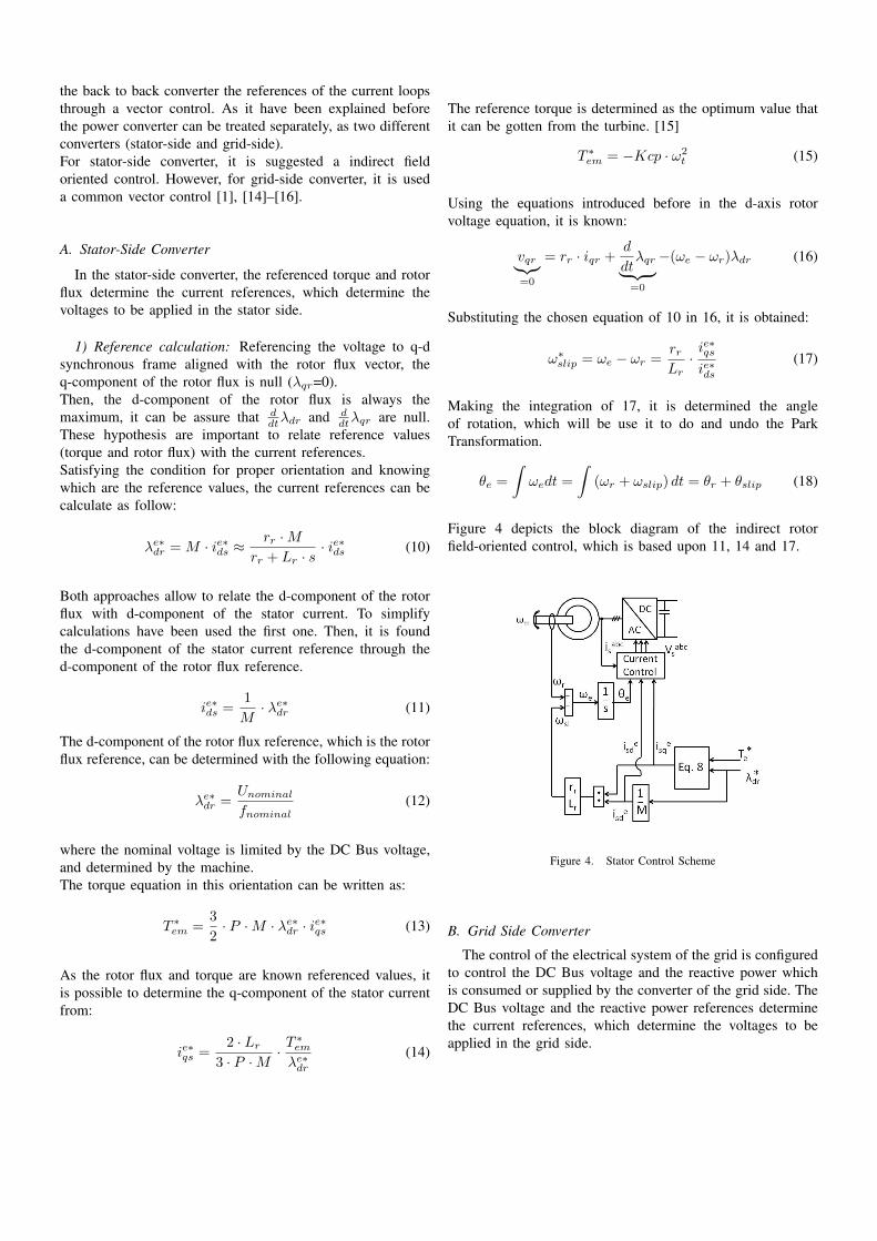
Figure 4 depicts the block diagram of the indirect rotorfield-oriented control, which is based upon 11, 14 and 17.
Figure 4. Stator Control Scheme
B. Grid Side Converter
The control of the electrical system of the grid is configuredto control the DC Bus voltage and the reactive power whichis consumed or supplied by the converter of the grid side. TheDC Bus voltage and the reactive power references determinethe current references, which determine the voltages to beapplied in the grid side.

1) Reference calculation: The q-axis may be aligned to thegrid voltage allowing active and reactive decoupled control.To control the reactive power, a ild reference is computed as:
i∗ld =2 ·Q∗l3 · vzq
(19)
The active power, which is responsible for the evolution ofthe dc bus is controlled by the ilq. A linear controller is usuallydesigned to control the dc bus voltage, and keep it constant.
Figure 5. Grid Control Scheme
Figure 5 depicts the block diagram of grid side control.
2) Current Loops: The current control is done by thefollowing state linearization feedback:
{vlqvld
}=
{−vlq + vzq − Ll · θg · ild
−vld + Ll · θg · ilq
}(20)
where vlq and vld are the voltage control value. Thedecoupling can be described as:
d
dt
{ilqild
}=
[− rl
Ll0
0 − rlLl
]{ilqild
}+
[ 1Ll
0
0 1Ll
]{vlqvld
}(21)
C. Current Controllers Tuning
Controllers have been designed using the so-called internalmodel control (IMC) [17]. The parameters of a PI controllerto obtain a desired bandwidth α, which appear because of alow-pass filter included by the IMC,are:
Kp = α · Lx Ki = α · rx (22)
Table IMECHANICAL PARAMETERS (S.I UNITS)
Jgen Jturb R Kgear
100 5·106 33 92.5
IV. SIMULATION RESULTS
The mechanical parameters and the electrical parameters[18], [19], can be seen in Tables I and II.During the simulation the system has been exposed to a windspeed variation to see the response of the control to these newstates. These variation can be seen in the figure 6.
Table IIELECTRICAL PARAMETERS (S.I UNITS)
rs rr Ls Lr M1.1 ·10−3 1.3 ·10−3 3.0636 ·10−3 3.0686 ·10−3 2.9936 ·10−3
rl Ll C P0.01 5.35 ·10−4 15.3 ·10−3 2
Figure 6. Input wind speed variation
In the Figure 7 is possible to see how the system evolvesfollowing the reference value. This is not constant due to ourfeedback of the rotation speed of the turbine, which either isconstant as it can be observed in Figure 8, make it changeuntil searching the optimum value. Can be observed how thetorque change to a new steady space every wind speed change.
In the Figure 9 is represented the Active Power valueevolution, which is almost constant. This is due to the control,what compensate the torque, which is not constant as can beseen in Figure 7)with the rotation speed turbine.
In the Figure 10 appears represented the difference betweenthe qd currents real values and the qd reference values. As itcan be seen, the system is working with the reference valuesbecause the error is almost zero permanently. There are peaks

Figure 7. System torque evolution
Figure 8. Turbine rotation velocity
Figure 9. Active power system evolution
on the starting point and the where the wind speed is changing.
Figure 10. Current error of the control system
V. CONCLUSION
This paper has presented a control technique to deal withSCIG connected to the grid through a full power converter.Both stator- and grid-side are considered, which detail thecontrol scheme to be used in each converter. The proposedtechnique allow control the stator-side without flux sensor in-side the machine, which assure less mechanical problems. Thecontrol strategy has been validated by means of simulations.
REFERENCES
[1] R. Teodorescu, “Flexible control of small wind turbines with grid failuredetection operating in stand-alone and grid-connected mode,” IEEETransactions on Power Electronics, vol. 19, pp. 1323–1332, 2004.
[2] A. Sikorski and A. Kuzma, “Cooperation of induction squirrel-cagegenerator with grid connected ac/dc/ac converter,” Bulletin of the PolishAcademy of Sciences; Technical Sciences, vol. 57, pp. 317–322, 2009.
[3] M. Imecs, “A survey of speed and flux control structures of squirrel-cage induction motor drives,” Acta Universitatis Sapientiae Electricaland Mechanical Engineering, Tech. Rep., 2009.
[4] J. Holtz, “Sensorless control of induction motor drives,” Proceedings ofthe IEEE, vol. 90, pp. 1359–1394, 2002.
[5] M. Imecs, C. Szabo, and J. J. Incze, “Stator-field-oriented control ofthe variable-excited synchronous motor: Numerical simulation,” in 7thInternational Symposium of Hungarian Researchers on ComputationalIntelligence, Budapest, Hungary, 2006.
[6] V. Vongmanee, “Emulator of wind turbine generator using dual invertercontrolled squirrel-cage induction motor,” in The Eighth InternationalConference on Power Electronics and Drive Systems, Taipei, Taiwan,,2009.
[7] R. Leidhold, G. Garcıa, and M. I. Valla, “Field-oriented controlledinduction generator with loss minimization,” IEEE Transactions onIndustrial Electronics, vol. 49, pp. 147–156, 2002.
[8] J. Faria, E. Margato, and M. Resende, “Self-excited induction generatorfor micro-hydro plants using water current turbines type,” ProceedingsINTELEC’05, pp. 107–112, 2005.
[9] C.-M. Ong, Dynamic Simulation of Electric Machinery using Mat-lab/Simulink. Prentice Hall, 1998.
[10] P. C. Krause, O. Wasynczuk, and S. D. Sudhoff, Analysis of ElectricMachinery and Drive Systems, 2nd ed., M. E. El-Hawary, Ed. IEEEPress, 2002.
[11] P. C. Krause, Analysis of Electric Machinery, S. Rao, Ed. McGraw-Hill,1986.
[12] O. Gomis-Bellmunt, A. Junyent-Ferre, A. Sumper, and J. Bergas-Jane, “Ride-through control of a doubly fed induction generator underunbalanced voltage sags,” IEEE Transactions on Energy Conversion,vol. 23, pp. 1036–1045, 2008.

[13] J. Bergas-Jane, “Control del motor d’induccio considerant els lımits delconvertidor i del motor,” Ph.D. dissertation, Universitat Politecnica deCatalunya, 2000.
[14] B. K. Bose, Modern Power Electronics and AC Drives. Prentice HallPTR, 2001.
[15] A. Junyent-Ferre, “Modelitzacio i control d’un sistema de generacioelectrica de turbina de vent,” Master’s thesis, ETSEIB-UPC, 2007.
[16] M. Molinas, B. Naess, W. Gullvik, and T. Undeland, “Cage inductiongenerators for wind turbines with power electronics converters in thelight of the new grid codes,” in European Conference on PowerElectronics and Applications, 2005.
[17] L. Harnefors and H.-P. Nee, “Model-based current control of ac ma-chines using the internal model control method,” IEEE Transactions onIndustry Applications, vol. 34, no. 1, pp. 133–141, Jan.-Feb. 1998.
[18] J. G. Slootweg, Wind Power in Power Systems. Wiley, 2005, ch.Reduced-order Modelling of Wind Turbines, pp. 555–585.
[19] Y. X. Dafeng Fu, “Study on linear dynamic model and analysis ofoperating characteristics of high-power vscf wind energy conversionsystem,” World Non-Grid-Connected Wind Power on Energy Conference,2009.
Jose Luis Domınguez-Garcıa (M’10) was born in Barcelona, Spain, in 1985.He received the Bs and Ms degrees in industrial engineering from the Schoolof Industrial Engineering of Barcelona (ETSEIB), Technical University ofCatalonia (UPC), Barcelona, Spain, in 2009. He developed his Ms Thesisin Oulun Yliopisto, Oulu, Finland. He is currently student of Ph. D. degreein electrical engineering. His research interest are modelling and control ofelectrical machines and power converters, renewable energy integration inpower systems and dynamic system theory.
Oriol Gomis-Bellmunt (S’05-M’07) received the degree in industrialengineering and the Ph.D. degree in electrical engineering from the Schoolof Industrial engineering of Barcelona (ETSEIB), Universitat Politecnica deCatalunya (UPC), Barcelona, Spain in 2001 and 2007, respectively.In 1999, he joined Engitrol S.L. where as a Project Engineer in theautomation and control industry implementing control and supervisionsystems in several cement, chemical, papel, and transportation industries. In2003, he developed part of his Ph.D. thesis in the DLR (German AerospaceCenter) in Braunschweig, Germany. Since 2004, he has been with theElectrical Engineering Department (DEE) of the UPC, where he is currentlya Lecturer and participates in the CITCEA-UPC research group. Since 2009,he is also with the Catalonia Institute for Energy Research (IREC). Hisresearch interests include the fields linked with smart actuators, electricalmachines, power electronics, renewable energy integration in power systems,industrial automation, and engineering education.
Lluıs Trilla-Romero was born in Barcelona, Spain, in 1981. He received theBs and Ms degrees in industrial engineering from the School of IndustrialEngineering of Barcelona (ETSEIB), Technical University of Catalonia(UPC), Barcelona, Spain, in 2006 and the Ms degree in Automatic Controland Robotics from the UPC in 2009. His current research interest includemodelling and control of electrical machines and power converters, itsapplication renewable generation system and its integration in the powersystem.
Adria Junyent-Ferre (SM’09) was born in Barcelona, Spain, in 1982. Hereceived the Bs and Ms degrees in industrial engineering from the Schoolof Industrial Engineering of Barcelona (ETSEIB), Technical University ofCatalonia (UPC), Barcelona, Spain, in 2007 and the Ms degree in AutomaticControl and Robotics from the UPC in 2009. He has been working on researchprojects as a grant student in the Electrical Engineering Department of theUPC since 2007. His current research interests include the modeling andcontrol of electrical machines and power converters and its use in renewablegeneration systems.