vec-1680k vacuum-tube preamplifier kit vec... · vec-1680k owner’s manual vacuum tube preamp 3...
TRANSCRIPT

VEC-1680K Owner’s Manual Vacuum Tube Preamp
1
INTRODUCTION General Information: If names like Eric Clapton, Jimi Hendrix, and B.B. King have personal meaning for you, you're gonna love this kit! Today's solid-state amps can't match the booming sound of the legendary tube-driven powerhouses built by Fender and Marshall. The key to that magic lies with the electron tube--or "valve"--which has much softer saturation characteristics than the sharply clipped response of transistor amplifiers.
With the VEC-1680K in line, your guitar's magnetic pick-ups are terminated with the true ultra-high impedance load they were designed to feed, which unleashes your instrument's natural full-bodied frequency response. And, when you crank up the gain, each note expands in richness with warm even-order harmonics, unlike the more jolting odd-order harmonics generated by transistors. Virtually every great tube guitar amp ever built used a 12AX7 in its preamplifier stage. When you fire up your VEC-1680K, you'll understand why!
Circuitry: The VEC-1680K uses a 12AX7 twin-triode, which is really two individual tubes packaged in one glass envelope. The first stage runs "wide open", with no manual gain control or negative feedback circuitry to load it down. A Gain (or drive) control then regulates how hard you push the preamp's second stage. Drive it lightly, and you get bell-like clarity. Drive it harder, and you'll introduce progressively more fullness and grit! Most of the preamp's distortion and coloring occurs in the second stage. At the preamp's output, the signal is attenuated back down to "guitar" level. The Output control provides added variable attenuation to set the optimum drive level for your power amp. A built-in relay connected to the audio jacks lets you bypass the preamp, or--with the click of a foot switch bring it on-line.
TOOLS AND SUPPLIES Construction Area: Kit construction requires a clean, smooth, and well-lighted area where you can easily organize and handle small parts without losing them. An inexpensive sheet of white poster board makes an excellent construction surface, while providing protection for the underlying table or desk. Diffused overhead lighting is a plus, and a supplemental high-intensity desk lamp is especially helpful for close-up work. Safety is always important! Use a suitable high-temperature stand for your soldering iron, and keep the work area free of clutter.
Universal Kit-building Tools: No special tools are required to complete this kit beyond common items normally used for bench construction. We recommend the following:
! Soldering Iron (grounded-tip and temperature-controlled preferred)

VEC-1680K Owner’s Manual Vacuum Tube Preamp
2
! High-temperature Iron Holder with Cleaning Sponge
! Solder, 60/40 or 37/63 with rosin or "no-clean" flux (.031" dia. is good size).
! Needle Nose Pliers or Surgical Hemostats
! Diagonal Cutters or "Nippy Cutters"
! Solder Sucker (squeeze or vacuum pump type), or Desoldering Braid
! Bright Desk Lamp
! Magnifying Glass
BEFORE YOU START BUILDING Experience shows there are four common mistakes builders make. Avoid these, and your kit will probably work on the first try! Here's what they are:
1. Installing the Wrong Part: It always pays to double-check each step. A 1K and a 10K resistor may look almost the same, but they may act very differently in an electronic circuit! Same for capacitors--a device marked 102 (or .001 uF) may have very different operating characteristics from one marked 103 (or .01uF).
2. Installing Parts Backwards: Always check the polarity of electrolytic capacitors to make sure the positive (+) lead goes in the (+) hole on the circuit board. ICs have a notch or dot at one end indicating the correct direction of insertion. Always double-check--especially before applying power to the circuit!
3. Faulty Solder Connections: Inspect for cold-solder joints and solder bridges. Cold solder joints happen when you don't fully heat the connection--or when metallic corrosion and oxide contaminate a component lead or pad. Solder bridges form when a trail of excess solder shorts pads or tracks together (see solder tips below).
4. Omitting or Misreading a Part: This is easier to do than you might think! Always double-check to make sure you completed each step in an assembly sequence.
Soldering Tips: Cleanliness and good heat distribution are the two secrets of professional soldering. Before you install and solder each part, inspect leads or pins for oxidation. If the metal surface is dull, sand with fine emery paper until shiny. Allow the tip of your iron to contact both the lead and pad for about one second (count "one-thousand-one") before feeding solder to the connection. Surfaces must become hot enough for solder to flow smoothly. Feed solder to

VEC-1680K Owner’s Manual Vacuum Tube Preamp
3
the opposite side of the lead from your iron tip--solder will wick around the lead toward the tip, wetting all exposed surfaces. Apply solder sparingly, and do not touch solder directly to the hot iron tip to promote rapid melting. Keep a damp sponge handy to wipe your soldering tip on. This removes excess solder, and keeps the tip properly tinned. If the iron is going to sit idling for long periods, wipe the tip, add some fresh solder, and unplug the iron.
Desoldering Tips: If you make a mistake and need to remove a part, follow these instructions carefully! First, grasp the component with hemostats, needle-nose pliers, or your fingers. Heat the pad beneath the lead you intend to extract, and pull gently. The lead should come out. Repeat for the other lead. Solder may fill in behind the lead as you extract it--especially if you are working on a double-sided board with plate-through holes. Should this happen, try heating the pad again and inserting a common pin into the hole. Solder won't stick to the pin's chromium plating. When the pad cools, remove the pin and insert the correct component. For ICs or multiple-pin parts, use desoldering braid to remove excess solder before attempting to extract the part. Alternatively, a low-cost vacuum-bulb or spring-loaded solder sucker may be used. Parts damaged or severely overheated during extraction should be replaced rather than reinstalled.
Work Habits: Kit construction requires the ability to follow detailed instructions and, in many cases, to perform new and unfamiliar tasks. To avoid making needless mistakes, work for short periods when you're fresh and alert. Recreational construction projects are more informative and more fun when you take your time. Enjoy!
Sorting and Reading Resistors: The electrical value of resistors is indicated by a color code (shown below). You don't have to memorize this code to work with resistors, but you do need to understand how it works:
1st Digit2nd DigitMultiplier
Tolerence
Black = 0 (tens)Brown = 1 (hundreds)Red = 2 (K)Orange = 3 (10K)Yellow = 4 (100K)Green = 5 (1Meg)
Blue = 6Violet = 7Gray = 8White = 9
Silver = 10%Gold = 5%
Resistor Color Code
(gold or silver)
When you look at a resistor, check its multiplier code first. Any resistor with a black multiplier band falls between 10 and 99 ohms in value. Brown designates a value between 100 and 999 ohms. Red indicates a value from 1000 to 9999 ohms, which is also expressed as 1.0K to 9.9K. An orange multiplier band designates 10K to 99K, etc. To inventory resistors, first separate them into

VEC-1680K Owner’s Manual Vacuum Tube Preamp
4
groups by multiplier band (make a pile of 10s, 100s, Ks, 10Ks, etc.). Next, sort each group by specific value (1K, 2.2K, 4.7K, etc). This procedure makes the inventory easier, and also makes locating specific parts more convenient later on during construction. Some builders find it especially helpful to arrange resistors in ascending order along a strip of double-sided tape.
Reading Capacitors: Unlike resistors, capacitors no longer use a color code for value identification. Instead, the value, or a 3-number code, is printed on the body.
Multilayer
271
(270 pF)
Ceramic Discs
|| 1uF35V
+-
104
Electrolytic 1 uF10 pF = 100
100 pF = 1011000 pF = 102 .001 uF = 102*.01 uF = 103.1 uF = 104
Value Code
102
(.001 uF) (.1 uF)
As with resistors, it's helpful to sort capacitors by type, and then to arrange them in ascending order of value. Small-value capacitors are characterized in pF (or pico-Farads), while larger values are labeled in uF (or micro-Farads). The transition from pF to uF occurs at 1000 pF (or .001 uF)*. Today, most monolithic and disc-ceramic capacitors are marked with a three-number code. The first two digits indicate a numerical value, while the last digit indicates a multiplier (same as resistors).
Electrolytic capacitors are always marked in uF. Electrolytics are polarized devices and must be oriented correctly during installation. If you become confused by markings on the case, remember the uncut negative lead is slightly shorter than the positive lead.
Danger---High Voltage Warning: Although your pre-amp runs from a 12-volt wall adapter, a second internal transformer boosts voltages back up to lethal levels to supply plate voltage to the 12AX7 tube! This voltage can painfully shock, injure, or even cause death if you touch it! Never work on tube-type equipment without first turning off and un-plugging the power source from the AC mains! Also, you should discharge power supply filter capacitors before working on tube amplifier circuitry. This added safety procedure will be described in the Testing and Alignment section of the manual.
PARTS LIST Your kit should contain all of the parts listed below. Please identify and inventory each item on the checklist before you start building. If any parts are missing or damaged, refer to the manual's warranty section for replacement

VEC-1680K Owner’s Manual Vacuum Tube Preamp
5
instructions. If you can't positively identify an unfamiliar item on the basis of the information given, set it aside until all other items are checked off. You may then be able to identify it by process of elimination. Finally, your kit will go together more smoothly if parts are organized by type and arranged by value ahead of time. Use this inventory as an opportunity to sort and arrange parts so you can identify and find them quickly.
" Qty Part Description Designation VEC P/N ! 2 100 ohm 2 watt resistor (brn-blk-brn) R12, R13 104-2100 ! 2 3.3K ohm ½ watt resistor (org-org-red) R1, R11 101-3330 ! 2 10K ohm ¼ watt resistor (brn-blk-org) R5, R7 100-4100 ! 1 22K ohm ¼ watt resistor (red-red-org) R8 100-4220 ! 2 390K ohm ¼ watt resistor (org-wht-yel) R3, R4 100-5390 ! 2 1M ohm ¼ watt resistor (brn-blk-grn) R2, R6 100-6100 ! 2 500K chassis mounted potentiometer R9, R10 153-5500-1 ! 1 .01 uF disc ceramic capacitor (103) C7 200-2100 ! 2 .1 uF disc ceramic capacitor (104) C10, C11 200-3100-1 ! 2 .22 uF multilayer capacitor (224) C3, C9 220-3220 ! 3 10 uF 350 volt electrolytic capacitor C1, C2, C6 270-5100x-6 ! 3 100 uF 25 volt electrolytic capacitor C4, C5, C8 270-6100-1 ! 1 1N4148 diode D6 300-4148 ! 5 1N4007 diode D1-D5 300-4007 ! 1 12AX7 tube V1 380-12AX7A ! 1 12.6 volt 1 amp power transformer T1 406-1114 ! 1 Power switch, SPST SW1 507-1028 ! 1 Relay, 2P2T RLY1 408-2042 ! 3 ¼” phone jack J1, J2, J4 601-1005 ! 1 2.1mm power jack J3 601-6121 ! 1 Power Adapter, 12 VAC @ 1 amp 407-1072 ! 1 Tube socket, 9 pin 625-12AX7A ! 2 Screw, 2-56 652-0375 ! 6 Nut, 2-56 705-0256 ! 6 Screw, self-tapping, type B 654S-0250B-B ! 6 Screw, 6-32 x ¼” 656-0250 ! 2 Kep Nut, 6-32 705-0632-K ! 3 Nut, metric 9mm 706-7075 ! 3 Flat washer 710-2550 ! 2 Spacer, ¾” threaded 6-32 716C-0750 ! 2 Knob 760-0033 ! 1 Shielded wire, RG316 (12”) 878-0316 ! 1 Orange and white twisted pair (4”) 871-2239 " Qty Part Description Designation VEC P/N ! 2 Hook-up wire (12”) 871-24xx-1200 ! 1 PC board, 2 sided 862-VEC1680 ! 1 Chassis, punched 800-VEC1680 ! 1 Chassis plate 804-VEC1680 ! 4 Stick-on rubber feet 770-1162


VEC-1680K Owner’s Manual Vacuum Tube Preamp
8
Good Not Good
The term solder means to solder the part's leads in place, and to inspect both (or all) solder connections for flaws or solder bridges. Nip off excess protruding leads with a sharp pair of side cutters.
Begin construction by locating the 2-sided PC board. Find the side of the board with long horizontal tracks on it. This will be called the solder-side during construction. Flip it over to the side with no tracks. This will be called the component side. Unless otherwise indicated, parts will be mounted on the component side (exceptions are three large electrolytic capacitors and two gain controls to be mounted on the other side).
Orient the PC board component-side up.
This kit has 11 fixed-value resistors. Mount these now, starting with the smallest value and moving to the largest. Before mounting each one, carefully bend both leads close to the resistor body to form right-angles, as shown below:
Locate two (2) 100 ohm 2 watt resistors (brown-black-brown).
! ! Install a 100 ohm at R12 and solder.
! ! Install a 100 ohm at R13 and solder.
Locate two (2) 3.3K ½ watt resistors (orange-orange-red).
! ! Install a 3.3K at R1 and solder.
! ! Install a 3.3K at R11 and solder.
Locate two (2) 10K ¼ watt resistors (brown-black-orange).
! ! Install a 10K at R5 and solder.
! ! Install a 10K at R7 and solder.
! ! Find a 22K ¼ watt resistor (red-red-orange). Install at R8 and solder.
Locate two (2) 390K ¼ watt resistors (orange-white-yellow).

VEC-1680K Owner’s Manual Vacuum Tube Preamp
9
! ! Install a 390K at R3 and solder.
! ! Install a 390K at R4 and solder.
Locate two (2) 1 Megohm ¼ watts resistors (brown-black-green).
! ! Install a 1 Megohm at R2 and solder.
! ! Install a 1 Megohm at R6 and solder.
This concludes installation of the 11 fixed-value resistors provided in your kit. Double-check for placement, making sure each value is installed where it belongs. The two 500K variable resistors (potentiometers) will be installed later on.
Next, install the kit's capacitors.
! ! Find the .01 uF, 100 volt, disc ceramic capacitor (.01 or 103). Install at C7 and solder.
Locate two (2) .1 uF, 500 volt, disc ceramic capacitors (.1 or 104).
! ! Install a .1 uF at C10 and solder.
! ! Install a .1 uF at C11 and solder.
Locate the two (2) .22 uF multilayer capacitors. Avoid using force or excessive heat when installing these. If the lead spacing isn't right, pre-form leads to the correct spacing before inserting into the PC board.
Incorrect Ooops! Correct
! ! Install a .22 uF at C3 and solder.
! ! Install a .22 uF at C9 and solder.
The remaining capacitors in your kit are electrolytic. Electrolytic caps are polarized and must be installed the correct way in order to work. Each capacitor's plus (+) mounting hole is marked on both the circuit board and parts placement diagram. If the markings on the capacitor body are unclear, the plus (+) lead is always the longer of the two.

VEC-1680K Owner’s Manual Vacuum Tube Preamp
10
+
Plus Lead
Locate the three (3) 100 uF electrolytic capacitors. Observing polarity:
! ! Install a 100 uF at C4 and solder.
! ! Install a 100 uF at C5 and solder.
! ! Install a 100 uF at C8 and solder.
The remaining three (3) 10 uF, 350 volt, electrolytic capacitors are mounted laying down flat on the opposite side of the PC board (solder side). Double-check capacitor polarity--high-voltage capacitors may literally explode with a "bang" if they're installed backwards!
+ +
_ _Solder Side
+_ C6
C1 C2
Flip the PC board over to its solder side and mount the 10 uF caps as shown:
! ! Install a 10 uF at C1 and solder.
! ! Install a 10 uF at C2 and solder.
! ! Install a 10 uF at C6 and solder.
This completes capacitor installation. Before moving on, check each electrolytic for correct polarity orientation.
While we're working on the solder side, this is a good time to install the two (2) 500K gain-control potentiometers. Locate them now. Before installing, inspect the type of potentiometer supplied with your kit. If the pins are located on the front side of the pot, use the front set of mounting holes provided on the PC board for installation. If the pins are on the rear, use the rear set of mounting

VEC-1680K Owner’s Manual Vacuum Tube Preamp
11
holes (see below). Also, using side cutters, remove the key tab from the side of each pot prior to installation.
Rear pins use rear holes. Front pins use front holes.
Nip off tab. Nip off tab.
! ! On the solder side of the PC board, mount a 500K pot at R9 and solder.
! ! Similarly, mount a 500K pot at R10 and solder.
Flip the PC board back to its component side to complete parts installation. The next six items to install are diodes. Like electrolytic capacitors, diodes are polarized devices that must be installed correctly. Always look for the banded end when installing.
! ! Find the 1N4148 diode (small glass body with band at one end). Observing polarity, install at D6 and solder.
Locate five (5) 1N4007 power diodes (black body, white band at one end). Observing polarity, install these as follows:
! ! Install a 1N4007 at D1 and solder.
! ! Install a 1N4007 at D2 and solder.
! ! Install a 1N4007 at D3 and solder.
! ! Install a 1N4007 at D4 and solder.
! ! Install a 1N4007 at D5 and solder.
Locate the DPDT miniature relay and note the pin configuration on its base. The pins are spaced so the relay fits only one way on the PC board. Be sure all pins enter their mounting holes and the relay sits flush with the PC board surface before soldering.

VEC-1680K Owner’s Manual Vacuum Tube Preamp
12
! ! Align and install the DPDT relay at RLY1. Holding firmly in place, solder all eight pins.
Now, install the preamp's 9-pin ceramic tube socket. As with the relay, these mounting pins are keyed to ensure proper positioning. Make sure all pins are firmly seated--and hold the socket in place when soldering.
! ! Align and install the ceramic tube socket at V1 and solder all 9 pins.
Next, install the twisted-pair filament leads to V1. Begin by locating the 4" length of the orange-and-white twisted hook-up provided with your kit:
! ! Dress each wire at both ends, removing about ¼" of insulation.
! ! Install the white wire at one end at GNDA-1 and solder.
! ! Install the companion orange wire at A-1 and solder.
! ! Install the other end of the white wire at GNDA-2 and solder.
! ! Install the companion orange wire at A2 and solder.
! ! Cut and dress a 6" length of hook-up wire and install one end at FOOT (this will be connected to the foot-switch jack later on). Solder.
Two shielded audio wires are used for the preamp's high-impedance INPUT and OUTPUT leads. Shielding prevents these lines from picking up stray AC hum. Note that only the circuit-board end of the lines are grounded. If both ends were grounded, it could set up a "ground loop" inside the amplifier enclosure that would introduce hum and noise. Prepare each cable as shown below:
1/2"Trim off shield
! ! Prep a 4" length of shielded cable, as shown.
! ! Connect the shield to GND5 and solder.
! ! Connect the inner conductor to OUTPUT and solder.
! ! Prep a 8" length of shielded cable, as shown.
! ! Connect the shield to GND4 and solder.
! ! Connect the inner conductor to INPUT and solder.

VEC-1680K Owner’s Manual Vacuum Tube Preamp
13
V1
A-1GNDA-1
GNDA-2
A-2
Input Output
GND4 GND5
To J1
To J4To J2
FilamentLine
RLY1
Foot
Input
Output
Footswitch
This completes circuit-board wiring of your VEC- Kit. The remaining point-to-point wiring will be done with the preamp circuit board mounted in its cabinet. Before moving on to that phase, give the circuit board a thorough QC (quality control) inspection. This will help you uncover assembly errors that might prevent it from working properly. Follow this procedure:
1. Compare parts locations with the parts-placement diagram. Was each part installed where it is supposed to be? Was the correct value used? Start at one side of the board and work your way across in an organized pattern.
2. Inspect the solder side of the board for cold-solder joins and solder bridges between tracks or pads. Use a magnifying glass to obtain a clear view of the track area. If you suspect a solder bridge, hold the board in front of a bright light for a better view. All joints should be smooth and shiny, indicating good solder wetting and flow. Resolder any beaded or dull-appearing connections.
3. Finally, check electrolytic capacitors and diodes for correct polarity. Does the plus (+) polarity symbol on the part agree with the pictorial and with the pattern on the PC board? Is the banded end of each diode positioned correctly?
Be sure to correct all errors before moving on--once the board is mounted in its cabinet, further inspections will require disassembly!
Begin final assembly by locating the chassis box and turning it upside down with the jack and control holes facing you. Looking into the box near the rear wall, find two mounting holes spaced approximately 4½” apart horizontally. Spacers will be mounted here to support the PC board. Find two (2) ¾” threaded aluminum spacers and two (2) 6-32 x ¼” screws.

VEC-1680K Owner’s Manual Vacuum Tube Preamp
14
! ! Install a spacer in the left-hand mounting hole (do not tighten).
! ! Repeat, installing one in the right-hand mounting hole.
Now, locate the PC board and remove the mounting hardware from the potentiometers.
Hold the PC board solder-side up with the gain control shafts facing toward you (the capacitors will be on the right side). Tilting the board toward you, guide the potentiometer shafts down into their mounting holes--allowing the rear of the PC board to clear the back lip on the chassis. Drop the PC board into position on its mounting spacers.
! ! Secure the PC board to its spacers with two 6-32 x ¼” screws.
! ! Tighten all hardware.
! ! Reinstall the potentiometer mounting hardware and tighten.
! ! Bring the ends of the audio and foot-switch leads out from under the board.
Each of these leads will be installed on the "tip" connection of a ¼” phone jack and installed in the chassis. Locate all three (3) ¼” phone jacks and their hardware--plus the three (3) 9mm spacer washers. Install as outlined below:
TipConnection
N.C.
Flat washerNut
������Spacer washer
! ! Connect the center conductor of the 4" shielded line to the tip connection on a ¼” jack and solder. Install the jack at Input on the chassis panel.
! ! Connect the center conductor of the 8" shielded line to the tip connection on a ¼” jack and solder. Install the jack at Output on the chassis panel.
! ! Connect the hook-up wire leading from FOOT to the tip connection on a ¼” jack and solder. Install the jack at Foot Switch on the chassis panel.
Locate the 12.6 volt 1.5-amp power transformer. Also, locate the remaining two (2) 6-32 x ¼” screws plus the two (2) kep nuts (thin square spring-like nuts).
! ! First cut the white lead off of the transformer. This lead is not needed.

VEC-1680K Owner’s Manual Vacuum Tube Preamp
15
! ! Refer to the pictorial diagram below, and position the 12.6 volt transformer so the black leads are toward the PC board and the red are toward the side of the chassis. Align the mounting tabs with the punched chassis holes.
! ! Using 6-32 hardware, secure the transformer in place--inserting each screw up through the chassis and securing it inside with a kep nut. Tighten both screws.
! ! Cut about half the lead length from both the black transformer leads. Dress both lead ends. Solder the back lead to TRANS1 and the front lead to TRANS2.
Input OutputFoot Switch
Power Jack
Power Switch
Red TransformerLeads
Black TransformerLeads
The preamp's power switch and power jack both mount from outside the chassis. Since space is tight inside, you'll find it easier to wire these prior to installation. This requires threading wires through the component mounting hole before attaching. Begin by locating the power switch and positioning it as shown (note the plastic partition between terminals #1 and #2). The switch tabs are raw copper and should be cleaned with fine emery cloth or a pencil eraser prior to attaching wires. Tab numbers are marked on the side of the switch.
! ! Thread the closest red transformer lead through the square switch mounting hole in the chassis panel. Dress the lead end and connect it to tab #1 without soldering.
! ! Cut a 4” length of hook-up wire and connect it to tab #1. Solder both leads.

VEC-1680K Owner’s Manual Vacuum Tube Preamp
16
! ! Cut a 6” length of hook-up wire and attach it to tab #2. Solder.
! ! Thread the 6” and 4” leads through the mounting hole.
! ! Holding the switch so tab #1 is up toward you, firmly press the switch into its mounting hole (it may take some pressure to collapse the plastic retainers on each end) . The switch should snap into place and hold securely.
! ! Connect the 4" wire from tab #1 of the switch to PWR on the PC board. Solder.
! ! Thread the 6" wire through the power-jack mounting hole at the rear of the chassis.
! ! Find the remaining red wire from the power transformer and thread that through the power jack mounting hole.
Locate the 2.1mm power jack and position as shown in the pictorial diagram. Note that there are three terminals. The terminal held in place by a rivet head is attached to the center pin of the power connector. This is the (+) connection.
! ! Attach the 6" lead from the power switch to the (+) connection on the power jack.
Find the terminal that exits the jack on the edge of the brown phenolic insulator. This is the (-) connector, or ground.
! ! Cut a 4" length of hook-up wire and dress both ends.
! ! Connect one end to the (-) tab of the power jack without soldering.
! ! Connect the remaining red lead from the power transformer to the (-) tab of the power jack and solder both leads in place.
Find the two (2) 2-56 screws and matching nuts.
! ! Install the power jack and secure it in place with 2-56 hardware.
! ! Connect the 4" lead from the (-) side of the power jack to GND on the PC board and solder.
Locate the 12AX7 tube and remove it from its box. Note that the tube's 9 pins are keyed to insert into the socket only one way. Turn the chassis over, find the socket at V1 (through the hole in the top), and align the tube pins with the socket holes.
! ! Carefully insert the 12AX7 tube into its socket (V1), taking care not to bend or fold over any pins.

VEC-1680K Owner’s Manual Vacuum Tube Preamp
17
Before installing the control knobs, set turn potentiometer shafts fully counterclockwise.
! ! Find a knob and install it on one of the potentiometers. Set the knob pointer to the 7-o'clock position and tighten the set screw.
! ! Repeat knob installation for the second potentiometer.
Locate the bottom cover for the chassis plus the six (6) self-tapping screws.
! ! Install the bottom chassis cover and secure.
! ! Find the sheet with four (4) rubber stick-on feet attached. Install a rubber foot at each corner of the bottom panel.
This concludes assembly of your VEC-1680K preamp kit.
High Voltage Warning: Your preamp's 12AX7 tube operates at potentially lethal voltages. Please read the Testing and Alignment section of this manual carefully before applying power or attempting to operate your preamp!
TESTING AND ALIGNMENT The VEC-1680K preamp has no internal adjustments and should work as specified without additional set-up. However, there's always the remote possibility that a construction error or defective component could prevent proper operation. Before attempting to use your preamp, follow this initial test procedure:
1. Turn both controls (Gain and Output) fully counter-clockwise.
2. Make sure the Power switch is Off.
Note: Do not plug in an instrument or amplifier at this stage of the test.
3. Locate the 12-VAC wall adapter and plug its cord into the 2.1mm power jack.
4. Plug the wall adapter into a 110 VAC mains.
5. Turn the Power switch On. The tube's filament should light.
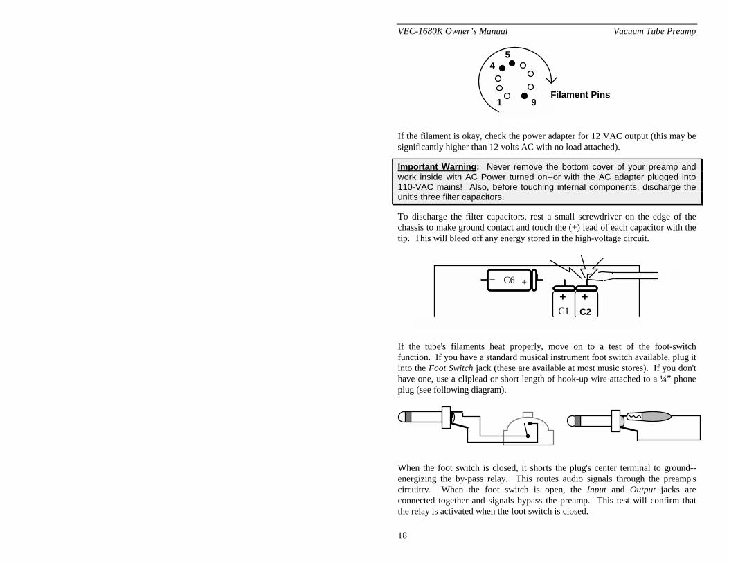
If the filament fails to light, turn the preamp Off at once. First, check the 12AX7 filament for continuity. Remove the tube and hold it with pins facing you. The first pin clockwise of the gap is pin 1. Count to pins 4 and 5, and check resistance with an ohm meter. If the filament is good, you'll see a short. Pin 9 is the filament's center tap.
VEC-1680K Owner’s Manual Vacuum Tube Preamp
18
1 9
45
Filament Pins
If the filament is okay, check the power adapter for 12 VAC output (this may be significantly higher than 12 volts AC with no load attached).
Important Warning: Never remove the bottom cover of your preamp and work inside with AC Power turned on--or with the AC adapter plugged into 110-VAC mains! Also, before touching internal components, discharge the unit's three filter capacitors.
To discharge the filter capacitors, rest a small screwdriver on the edge of the chassis to make ground contact and touch the (+) lead of each capacitor with the tip. This will bleed off any energy stored in the high-voltage circuit.
+_ C6
C1+
C2+
If the tube's filaments heat properly, move on to a test of the foot-switch function. If you have a standard musical instrument foot switch available, plug it into the Foot Switch jack (these are available at most music stores). If you don't have one, use a cliplead or short length of hook-up wire attached to a ¼” phone plug (see following diagram).
When the foot switch is closed, it shorts the plug's center terminal to ground--energizing the by-pass relay. This routes audio signals through the preamp's circuitry. When the foot switch is open, the Input and Output jacks are connected together and signals bypass the preamp. This test will confirm that the relay is activated when the foot switch is closed.

VEC-1680K Owner’s Manual Vacuum Tube Preamp
19
6. Connect an instrument to the Input jack of the preamp.
7. Connect a patch cord between the Output jack and your guitar amp.
8. Turn the preamp's Gain and Output controls off (counter-clockwise).
9. Make sure the preamp's power switch is On.
With the foot switch open, your guitar should bypass the preamp and play through the power amplifier normally--as if patched directly in. With the foot switch closed, the guitar signals should not reach the amp because both preamp gain controls are fully down. If the relay fails to close, check the preamp's relay circuit for errors.
If the relay circuit is working, check the operation of the preamp itself. With the foot switch closed:
10. Set the preamp's Gain control at 12:00 (half open).
11. Slowly increase the Output control while plucking a note.
You should hear the guitar become progressively louder. Bring the Output control up until the volume through the preamp roughly matches the volume when in bypass mode setting. If strong hum or oscillation occurs, turn the Output control down quickly and turn the preamp off. This indicates an assembly problem in the preamp circuitry that needs correction. If the preamp is operating correctly, you're done!
VEC-1680K Owner’s Manual Vacuum Tube Preamp
20
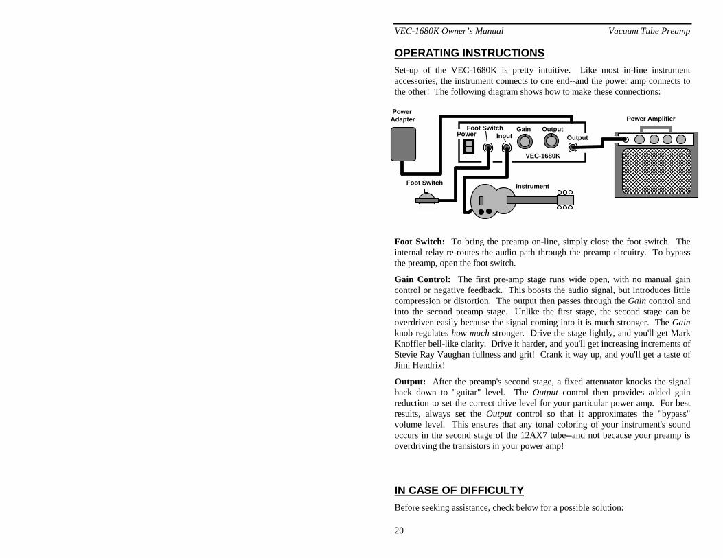
OPERATING INSTRUCTIONS Set-up of the VEC-1680K is pretty intuitive. Like most in-line instrument accessories, the instrument connects to one end--and the power amp connects to the other! The following diagram shows how to make these connections:
Foot SwitchInputPower Output
Gain Output
��������������������
PowerAdapter
Foot Switch Instrument
Power Amplifier
VEC-1680K
Foot Switch: To bring the preamp on-line, simply close the foot switch. The internal relay re-routes the audio path through the preamp circuitry. To bypass the preamp, open the foot switch.
Gain Control: The first pre-amp stage runs wide open, with no manual gain control or negative feedback. This boosts the audio signal, but introduces little compression or distortion. The output then passes through the Gain control and into the second preamp stage. Unlike the first stage, the second stage can be overdriven easily because the signal coming into it is much stronger. The Gain knob regulates how much stronger. Drive the stage lightly, and you'll get Mark Knoffler bell-like clarity. Drive it harder, and you'll get increasing increments of Stevie Ray Vaughan fullness and grit! Crank it way up, and you'll get a taste of Jimi Hendrix!
Output: After the preamp's second stage, a fixed attenuator knocks the signal back down to "guitar" level. The Output control then provides added gain reduction to set the correct drive level for your particular power amp. For best results, always set the Output control so that it approximates the "bypass" volume level. This ensures that any tonal coloring of your instrument's sound occurs in the second stage of the 12AX7 tube--and not because your preamp is overdriving the transistors in your power amp!
IN CASE OF DIFFICULTY Before seeking assistance, check below for a possible solution:

VEC-1680K Owner’s Manual Vacuum Tube Preamp
21
Does not turn on: Is the power adapter plugged in? Does it have 12 VAC output? Is the tube firmly seated in its socket?
Hum on Instrument: Are patch cables in good condition (no open grounds)? Try flipping the polarity switch on the power amp.
Distorted Audio at all settings: Check condition of the tube. Is there a bluish glow or does the tube make a strong ringing sound when tapped with a pencil eraser (is it microphonic)? Tubes deteriorate with age and require periodic replacement.
If you have the necessary tools and technical skills to troubleshoot and repair high-voltage equipment, voltage analysis is a good way to localize trouble. Here are the normal voltage readings for the 12AX7. Any variation over 10% from these values may indicate a problem area in the preamp's circuitry.
Important Warning: Potentially lethal voltages are present in your preamplifier. Never attempt to take "live" voltage readings on tube-type equipment unless you are specially trained and qualified to do so!
12AX7 Voltage Chart
Pin-1 80 V Pin-2 0.1 V Pin-3 1.4 V
Pin-6 90 VPin-7 .1 VPin-8 1.0 V
Pin-4 to Pin-5 13-VACPin-4 to Pin-9 6.5-VAC
V1a V1b
If these checks fail to uncover the problem, repeat the "QC" check one more time. Service records show that, for most malfunctioning kits, outright component failure is relatively rare. In most cases, the culprit is a misplaced part, reverse-polarized capacitor, or a faulty solder connection. If, despite your best effort, you cannot solve the problem, kit repair services are available through Vectronics. See the warranty on the inside front cover for complete instructions.
THEORY OF OPERATION The VEC-1680K preamp uses a 12AX7 high-mu dual triode at V1, a tube designed especially for low-level audio preamplifier applications. The first stage is optimized for linearity, with the grid-leak bias circuit (R6) chosen to present minimal loading to magnetic instrument pickups. Output from this stage is AC-
VEC-1680K Owner’s Manual Vacuum Tube Preamp
22
coupled into gain control R9, which establishes the drive level for the following stage. The second stage is configured for high gain, but its plate supply is set intentionally "soft". This allows the stage to be driven into saturation easily in order to create a variety of special effects and tonal colorings. The output level of the second stage, which is many orders of magnitude stronger that "instrument level", is attenuated back down to a useful drive level through a combination fixed and variable attenuator network (R4, R5, and R10).
Foot-switch driven relay RLY1 controls signal routing by either connecting the preamplifier circuitry on line, or bypassing it with a direct connection between the Input and Output jacks.
The preamp is isolated from the AC line by a 12 volt AC adapter. This feeds V1's filament circuit directly, and also energizes the preamp's two built-in DC supplies. A simple low-voltage supply provides smoothed DC for the foot-switch relay circuit (D5/C8). A second high-voltage supply develops plate voltage for V1 by transforming 12-VAC back to AC line level through T1. Diode bridge D1-D4 converts this energy to DC, where it is smoothed through filter network C1, C2, C6 and R1, R11.


VEC-1680K Owner’s Manual Vacuum Tube Preamp
24
ENCLOSURE
Vectronics has designed a matching enclosure just for your VEC-1680K Vacuum Tube Audio Preamplifier Kit. The matching enclosure is an all metal cover, with mounting screws, to protect your tube. The Vectronics model number for the matching enclosure is VEC-1680KC.
To install your VEC-1680KC matching enclosure follow these instructions:
1. Remove all debris and oil from the enclosure. You can do this with a piece of cloth and alcohol.
2. Find the four (4) self-tapping (#4 x ¼”, type B) screws.
3. Align the enclosure with the four pilot holes.
4. With a philips head type screw drive, secure the enclosure using the self-tapping screws. The screws should be snug—do not over tighten.
