vbs – vertebral body stenting system. minimally invasive...
TRANSCRIPT

VBS – Vertebral Body StentingSystem. Minimally invasive,percutaneous, reconstructive treatmentfor vertebral body fractures.
Technique Guide

Image intensifier control
WarningThis description alone does not provide sufficient background for direct use ofthe instrument set. Instruction by a surgeon experienced in handling theseinstruments and the attendance of a VBS training in order to know the VBSinstrumentation and technique is highly recommended.
Reprocessing, Care and Maintenance of Synthes InstrumentsFor general guidelines, function control and dismantling of multi-part instruments,please refer to: www.synthes.com/reprocessing

Table of Contents
Introduction
Surgical Technique
Product Information
Bibliography 48
VBS Vertebral Body Stenting System 2
AO Principles 4
Indications and Contraindications 5
Preoperative Planning 7
Preparation 8
Patient Positioning 11
Access Options 12
Instrument Positioning 13A With Guide Wires– A1 Transpedicular Access 14– A2 Extra-/Parapedicular Access 17B With Trocars– B1 Transpedicular Access 21– B2 Extra-/Parapedicular Access 22
Create Access Channel 23
Determine Stent Size 24
Optional: Use of VBB 25
Inflation of VBB 30
Using the VBS Catheter 34
Deployment of Stents 38
Cement Augmentation 42
Implants and Balloon-Catheters 44
Instruments 46
VBS Technique Guide Synthes 1
2 Synthes VBS Technique Guide
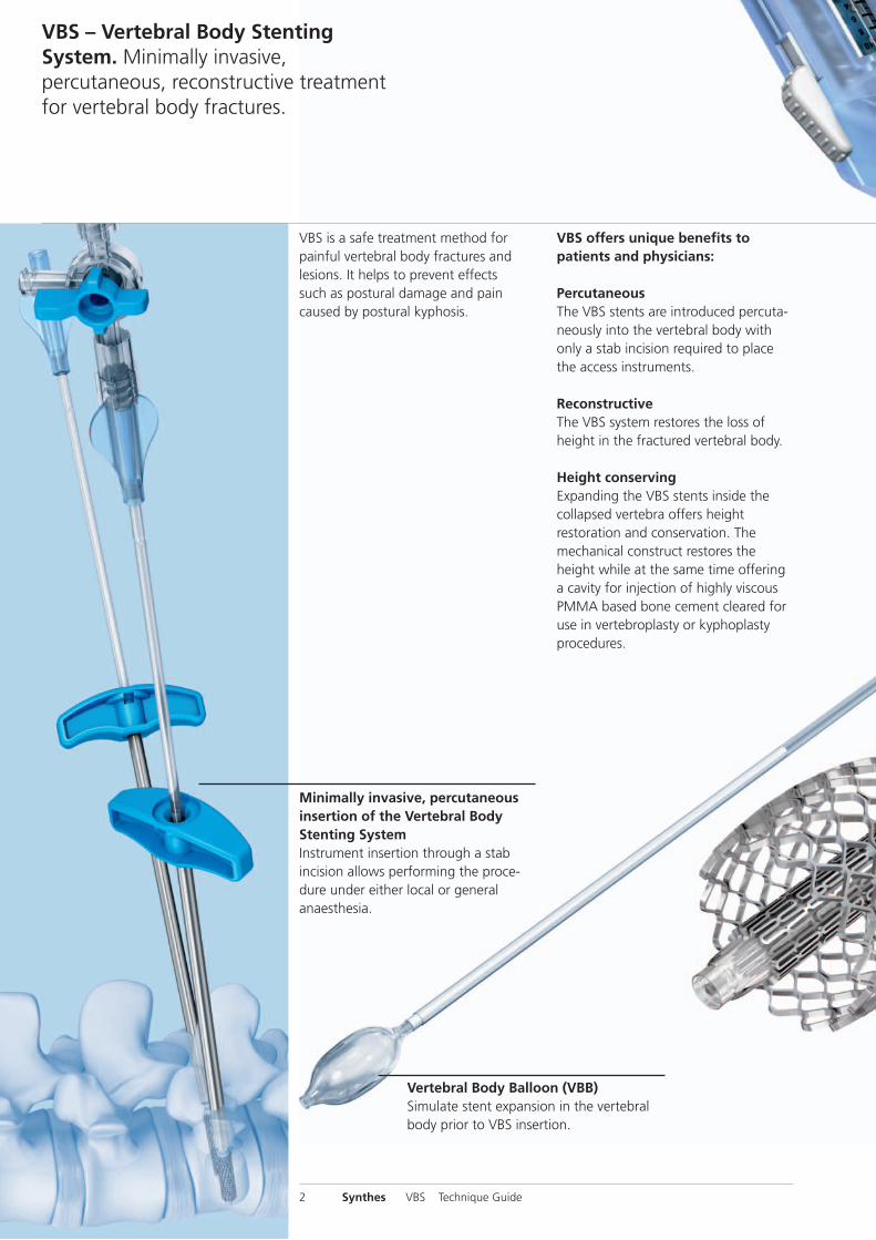
VBS is a safe treatment method forpainful vertebral body fractures and lesions. It helps to prevent effectssuch as postural damage and paincaused by postural kyphosis.
Vertebral Body Balloon (VBB)Simulate stent expansion in the vertebralbody prior to VBS insertion.
VBS – Vertebral Body StentingSystem. Minimally invasive,percutaneous, reconstructive treatmentfor vertebral body fractures.
Minimally invasive, percutaneousinsertion of the Vertebral BodyStenting SystemInstrument insertion through a stab incision allows performing the proce-dure under either local or generalanaesthesia.
VBS offers unique benefits to patients and physicians:
PercutaneousThe VBS stents are introduced percuta-neously into the vertebral body withonly a stab incision required to placethe access instruments.
ReconstructiveThe VBS system restores the loss ofheight in the fractured vertebral body.
Height conservingExpanding the VBS stents inside thecollapsed vertebra offers heightrestoration and conservation. The mechanical construct restores theheight while at the same time offeringa cavity for injection of highly viscousPMMA based bone cement cleared foruse in vertebro plasty or kyphoplastyprocedures.
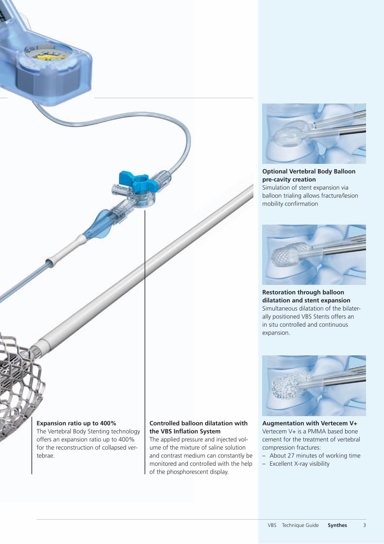
Restoration through balloondilatation and stent expansionSimultaneous dilatation of the bilater-ally positioned VBS Stents offers an in situ controlled and continuous expansion.
Optional Vertebral Body Balloonpre-cavity creationSimulation of stent expansion via balloon trialing allows fracture/lesionmobility confirmation
Augmentation with Vertecem V+Vertecem V+ is a PMMA based bonecement for the treatment of vertebralcompression fractures:– About 27 minutes of working time – Excellent X-ray visibility
Expansion ratio up to 400%The Vertebral Body Stenting technologyoffers an expansion ratio up to 400%for the reconstruction of collapsed ver-tebrae.
Controlled balloon dilatation withthe VBS Inflation SystemThe applied pressure and injected vol-ume of the mixture of saline solutionand contrast medium can constantly bemonitored and controlled with the helpof the phosphorescent display.
VBS Technique Guide Synthes 3
1 Müller ME, Allgöwer M, Schneider R, Willenegger H (1995) Manual of InternalFixation. 3rd, exp. a. completely revised ed. 1991. Berlin, Heidelberg, New York:Springer
2 Aebi M, Arlet V, Webb JK (2007) AOSPINE Manual (2 vols), Stuttgart, New York:Thieme
4 Synthes VBS Technique Guide
In 1958, the AO formulated four basic principles, which havebecome the guidelines for internal fixation1. They are:– Anatomic reduction– Stable fixation– Preservation of blood supply– Early, active mobilization
The fundamental aims of fracture treatment in the limbsand fusion of the spine are the same. But a specific goal ofspine treatment is to restore as much function as possibleto the injured neural elements.1
AO Principles as applied to the spine 2
Anatomic reductionRestoration of normal spine alignment improves the biome-chanics of the spine and reduces pain by reestablishing andmaintaining the natural curvature and the protective functionof the spine.
Stable fixationIn the spine, the goal of internal fixation is to maintain notonly the integrity of a mobile segment, but also to maintainthe balance and the physiologic three-dimensional formof the spine. A stable spinal segment allows bony fusion atthe junction of the lamina and pedicle.
AO Principles
Preservation of blood supplyThe proper atraumatic technique enables minimal retractionor disturbance of the nerve roots and dura, and maintainsthe stability of the facet joints. The ideal surgical techniqueand implant design minimize damage to anatomical struc-tures, i.e. facet capsules and soft tissue attachment remainintact, and create a physiological environment that facilitateshealing.
Early, active mobilizationThe ability to restore normal spinal anatomy may permit theimmediate reduction of pain, resulting in a more active, func-tional patient. The reduction in pain and improved functioncan result when a stable spine is achieved.
Indications and Contraindications
Intended useThe VBS System is intended for the reduction of painful vertebral compression fractures and/or creation of a void incancellous bone in the spine for the treatment of levels ranging from Th5-L5. It is intended to be used in combina-tion with a legally-marketed PMMA 1 based bone cement adequately indicated for use in vertebroplasty or kyphoplastyprocedures.
Note: Refer to the manufacturer’s directions accompanyingthe bone cement for specific information on its use, precau-tions and warnings.
Indications– Painful osteoporotic vertebral compression fractures with-
out posterior wall involvement. Classified after Genant,Grade 2 and Grade 3.
– Painful vertebral compression fractures classified after theAO classification:A1.1 Endplate impactionA1.2 Wedge impaction fractureA1.3 Vertebral body collapseA3.1 Incomplete burst fracture; matter of discretion
(depending on the degree of posterior wall involve-ment, internal fixation must be used in addition)
In combination with internal fixation:A3.1 Incomplete burst fractureA3.2 Burst-split fracture; matter of discretion (the extent
of the gap width should not be too wide)B1.2 Posterior disruption predominantly ligamentous
associated with type A fracture of the vertebral bodyB2.3 Posterior disruption predominantly osseous with
type A fracture of the vertebral body– Palliative treatment of osteolytic lesions located within the
vertebral body with intact cortical shell. Classified afterTomita Type 1.
Contraindications– Lesions requiring open anterior column reconstruction– Acute or chronic systemic or localized spinal infections
1 Note: The long-term effects of PMMA based cements on the vertebral column areunknown. Therefore, the treating physician should weigh the benefits of theapplication of the PMMA based cement in younger patients against the potentialrisks.
VBS Technique Guide Synthes 5

6 Synthes VBS Technique Guide
Preoperative Planning
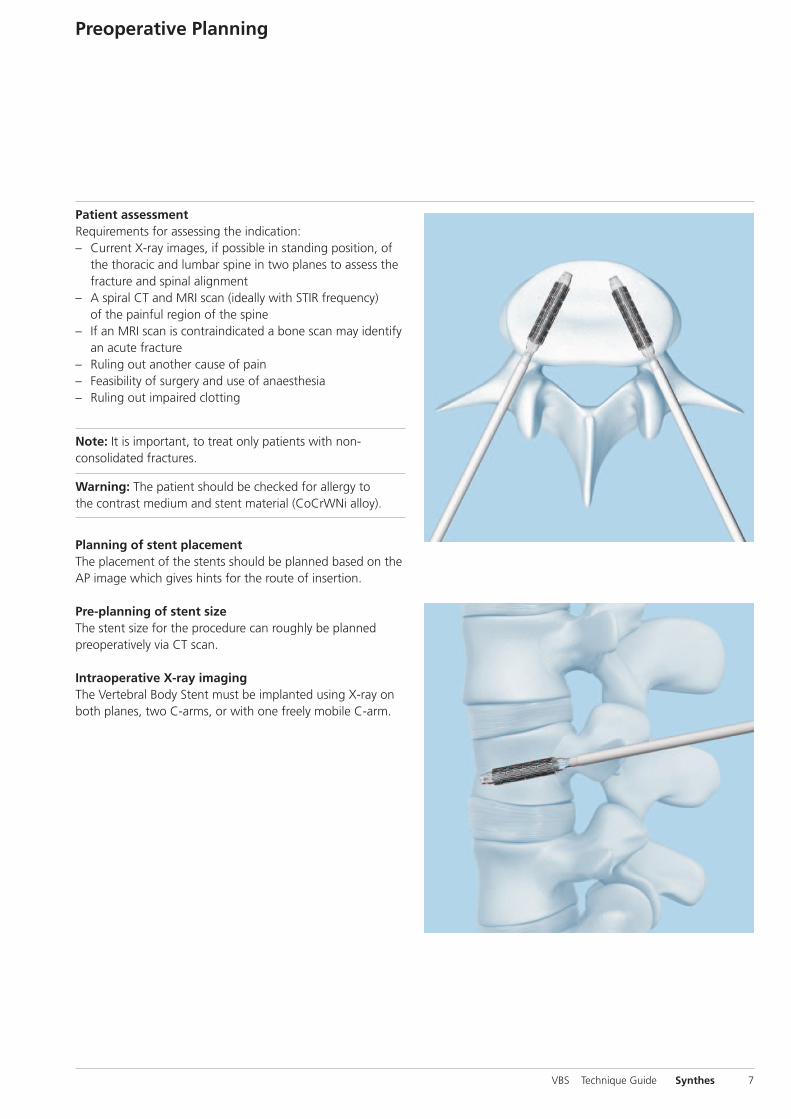
Patient assessmentRequirements for assessing the indication:– Current X-ray images, if possible in standing position, of
the thoracic and lumbar spine in two planes to assess thefracture and spinal alignment
– A spiral CT and MRI scan (ideally with STIR frequency)of the painful region of the spine
– If an MRI scan is contraindicated a bone scan may identifyan acute fracture
– Ruling out another cause of pain– Feasibility of surgery and use of anaesthesia– Ruling out impaired clotting
Note: It is important, to treat only patients with non- consolidated fractures.
Warning: The patient should be checked for allergy tothe contrast medium and stent material (CoCrWNi alloy).
Planning of stent placementThe placement of the stents should be planned based on theAP image which gives hints for the route of insertion.
Pre-planning of stent sizeThe stent size for the procedure can roughly be planned preoperatively via CT scan.
Intraoperative X-ray imagingThe Vertebral Body Stent must be implanted using X-ray onboth planes, two C-arms, or with one freely mobile C-arm.
VBS Technique Guide Synthes 7
1
2
8 Synthes VBS Technique Guide
Preparation
Instrument preparation
Instrument Set
03.804.512S Vertebral Body Stent Access Kit
Instrument
03.804.413S Inflation System
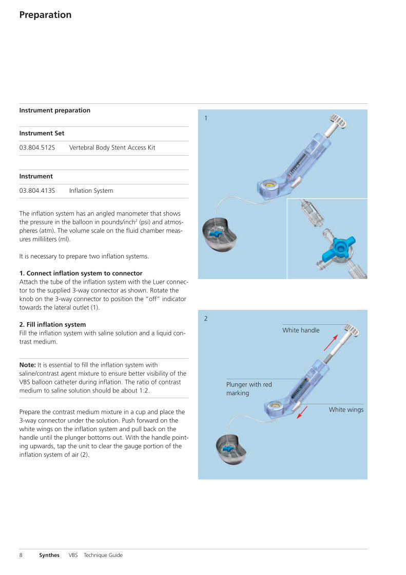
The inflation system has an angled manometer that showsthe pressure in the balloon in pounds/inch2 (psi) and atmos-pheres (atm). The volume scale on the fluid chamber meas-ures milliliters (ml).
It is necessary to prepare two inflation systems.
1. Connect inflation system to connectorAttach the tube of the inflation system with the Luer connec-tor to the supplied 3-way connector as shown. Rotate theknob on the 3-way connector to position the “off” indicatortowards the lateral outlet (1).
2. Fill inflation systemFill the inflation system with saline solution and a liquid con-trast medium.
Note: It is essential to fill the inflation system with saline/contrast agent mixture to ensure better visibility of theVBS balloon catheter during inflation. The ratio of contrastmedium to saline solution should be about 1:2.
Prepare the contrast medium mixture in a cup and place the3-way connector under the solution. Push forward on thewhite wings on the inflation system and pull back on thehandle until the plunger bottoms out. With the handle point-ing upwards, tap the unit to clear the gauge portion of theinflation system of air (2).
White handle
White wings
Plunger with red marking

3Then hold the inflation system with the handle facing down-ward, and rotate the handle clockwise to expel all the air inthe barrel until solution starts to emerge. Keep turning thehandle clockwise until the leading edge of the red mark onthe plunger reaches to approximately 3 to 4 ml under thezero marking or until the red marker on the plunger isaligned with the black line above the ml sign, underneaththe zero marking (3).
The inflation system has now been preparedaccordingly and can be set aside. Repeat for the secondinflation system.
Tip: The white wings may be pushed to unlock the plungerwhen large changes to the handle position are desired.The handle must be moved carefully to avoid overshootingthe desired target.
Warning: If the buttons (white wings) do not return to thelocked position, do not force them as this could damagethe plunger. Turn the handle gently, and the buttons (whitewings) will return automatically to the locked position.
VBS Technique Guide Synthes 9
~5 mm
1
10 Synthes VBS Technique Guide
Preparation
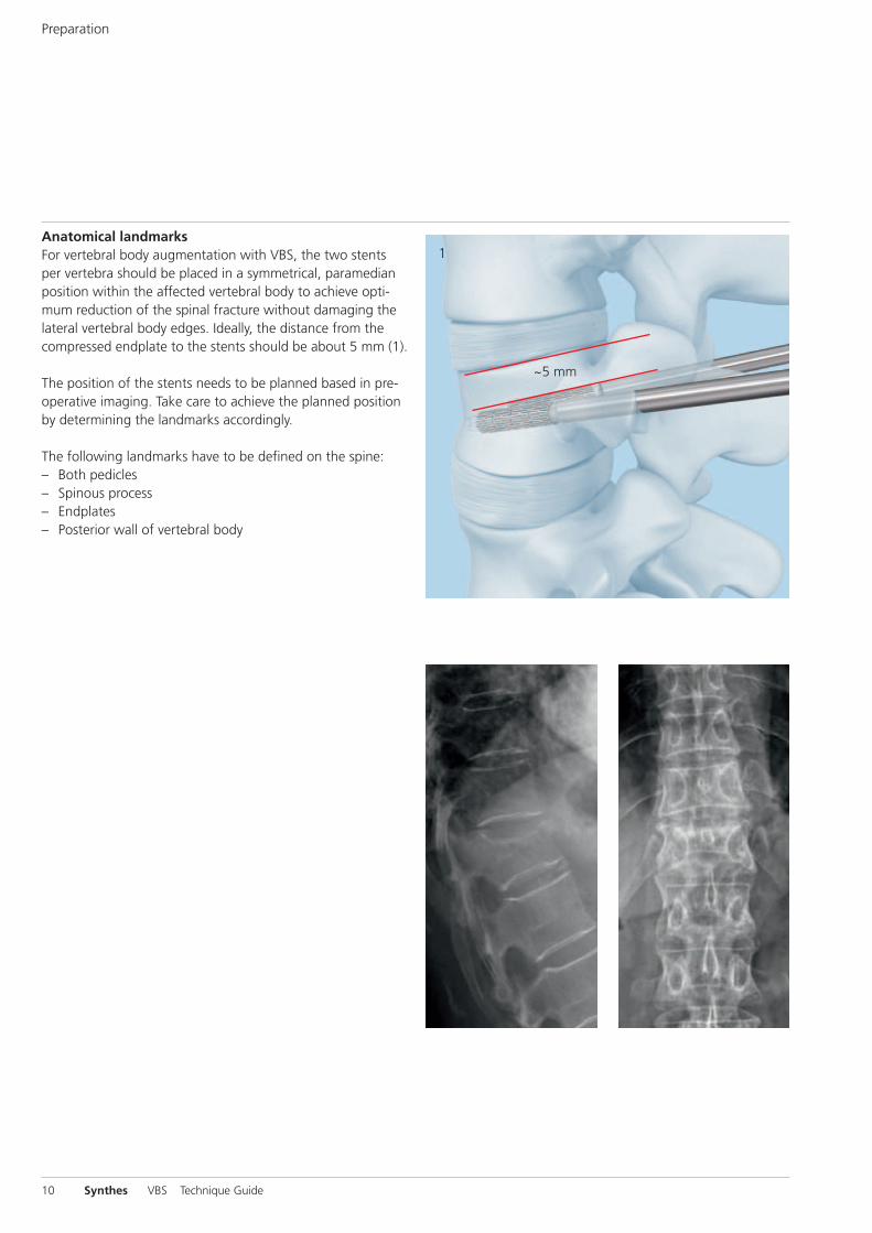
Anatomical landmarksFor vertebral body augmentation with VBS, the two stentsper vertebra should be placed in a symmetrical, paramedianposition within the affected vertebral body to achieve opti-mum reduction of the spinal fracture without damaging thelateral vertebral body edges. Ideally, the distance from thecompressed endplate to the stents should be about 5 mm (1).
The position of the stents needs to be planned based in pre-operative imaging. Take care to achieve the planned positionby determining the landmarks accordingly.
The following landmarks have to be defined on the spine:– Both pedicles– Spinous process– Endplates– Posterior wall of vertebral body

Patient Positioning
Place the patient in the prone position on a lumbar support.The table must be radiolucent in both planes.
The OR table should allow free manipulation of the C-armover the operative site in both planes.
VBS Technique Guide Synthes 11
1
2
12 Synthes VBS Technique Guide
Access Options
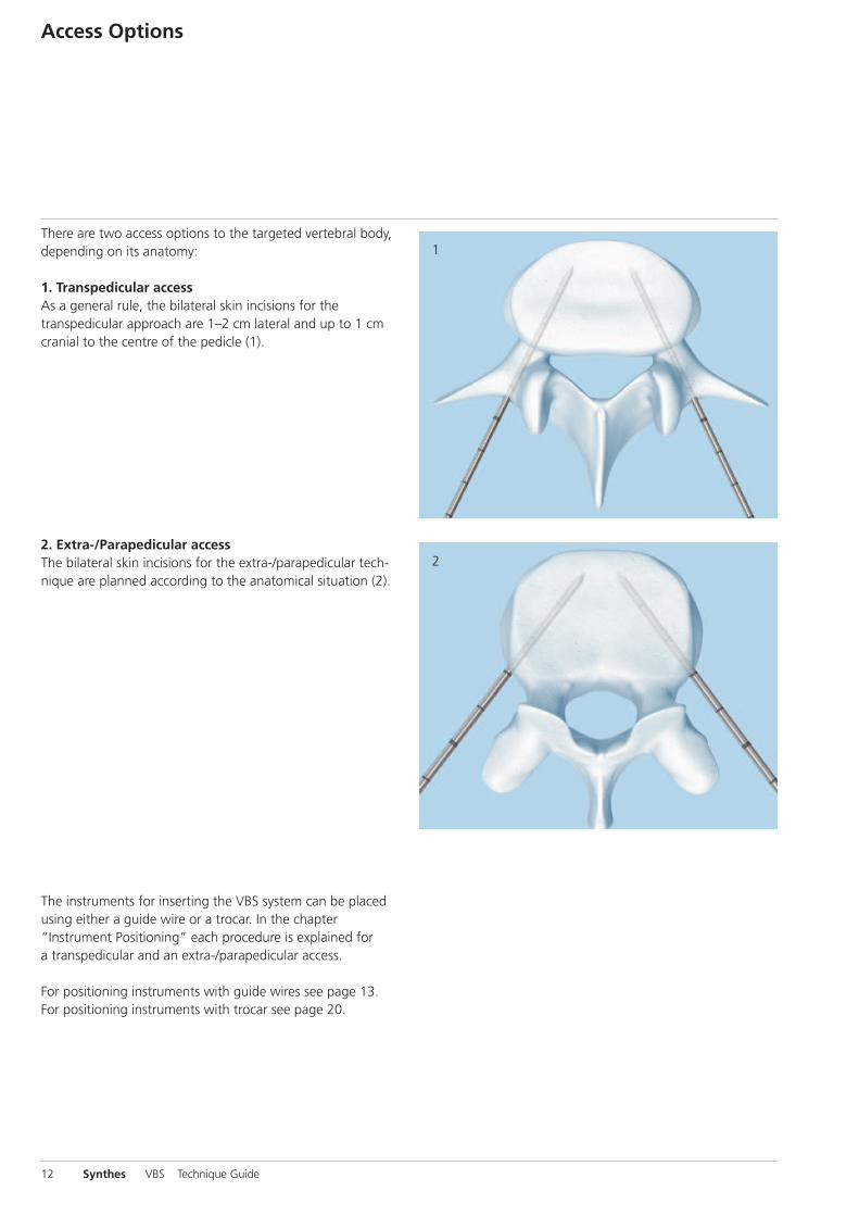
There are two access options to the targeted vertebral body,depending on its anatomy:
1. Transpedicular accessAs a general rule, the bilateral skin incisions for thetranspedicular approach are 1–2 cm lateral and up to 1 cmcranial to the centre of the pedicle (1).
2. Extra-/Parapedicular accessThe bilateral skin incisions for the extra-/parapedicular tech-nique are planned according to the anatomical situation (2).
The instruments for inserting the VBS system can be placedusing either a guide wire or a trocar. In the chapter “Instrument Positioning” each procedure is explained fora transpedicular and an extra-/parapedicular access.
For positioning instruments with guide wires see page 13.For positioning instruments with trocar see page 20.
1
5 mm
Instrument PositioningA With Guide Wires
Instrument Set
03.804.512S Vertebral Body Stent Access Kit
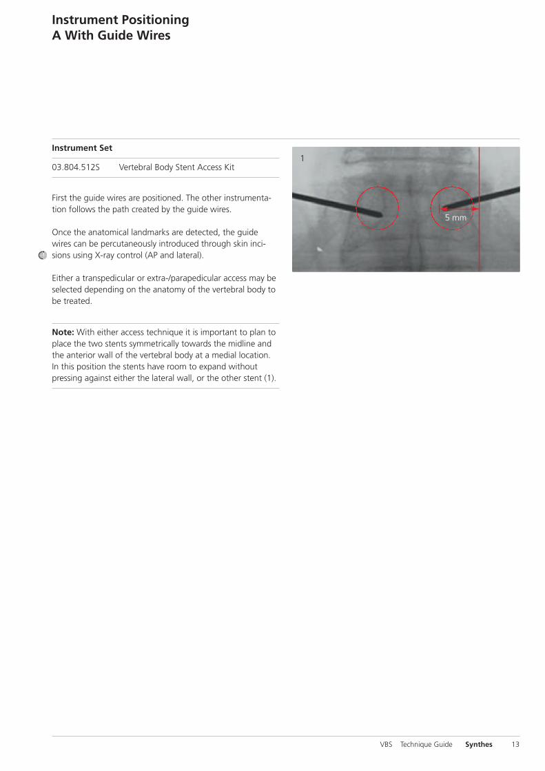
First the guide wires are positioned. The other instrumenta-tion follows the path created by the guide wires.
Once the anatomical landmarks are detected, the guidewires can be percutaneously introduced through skin inci-sions using X-ray control (AP and lateral).
Either a transpedicular or extra-/parapedicular access may beselected depending on the anatomy of the vertebral body tobe treated.
Note: With either access technique it is important to plan toplace the two stents symmetrically towards the midline andthe anterior wall of the vertebral body at a medial location.In this position the stents have room to expand withoutpressing against either the lateral wall, or the other stent (1).
VBS Technique Guide Synthes 13
14 Synthes VBS Technique Guide
A1 Transpedicular Access
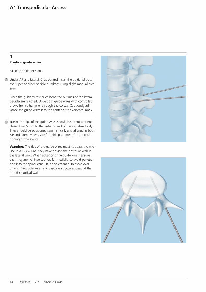
1Position guide wires
Make the skin incisions.
Under AP and lateral X-ray control insert the guide wires tothe superior outer pedicle quadrant using slight manual pres-sure.
Once the guide wires touch bone the outlines of the lateralpedicle are reached. Drive both guide wires with controlledblows from a hammer through the cortex. Cautiously ad-vance the guide wires into the center of the vertebral body.
Note: The tips of the guide wires should be about and notcloser than 5 mm to the anterior wall of the vertebral body.They should be positioned symmetrically and aligned in bothAP and lateral views. Confirm this placement for the posi-tioning of the stents.
Warning: The tips of the guide wires must not pass the mid-line in AP view until they have passed the posterior wall inthe lateral view. When advancing the guide wires, ensurethat they are not inserted too far medially, to avoid penetra-tion into the spinal canal. It is also essential to avoid over -driving the guide wires into vascular structures beyond theanterior cortical wall.
1
2
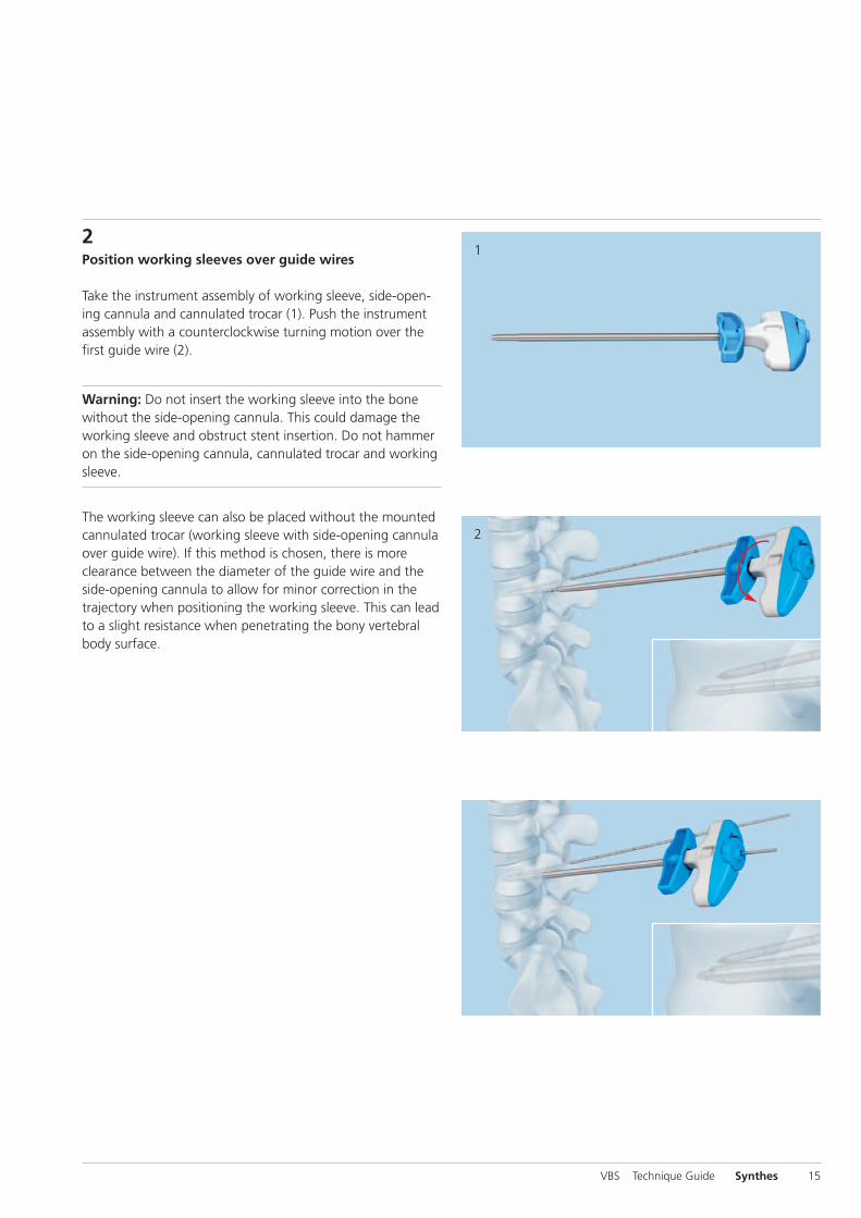
2Position working sleeves over guide wires
Take the instrument assembly of working sleeve, side-open-ing cannula and cannulated trocar (1). Push the instrumentassembly with a counterclockwise turning motion over thefirst guide wire (2).
Warning: Do not insert the working sleeve into the bonewithout the side-opening cannula. This could damage theworking sleeve and obstruct stent insertion. Do not hammeron the side-opening cannula, cannulated trocar and workingsleeve.
The working sleeve can also be placed without the mountedcannulated trocar (working sleeve with side-opening cannulaover guide wire). If this method is chosen, there is moreclearance between the diameter of the guide wire and theside-opening cannula to allow for minor correction in thetrajectory when positioning the working sleeve. This can leadto a slight resistance when penetrating the bony vertebralbody surface.
VBS Technique Guide Synthes 15
4
5
6
16 Synthes VBS Technique Guide
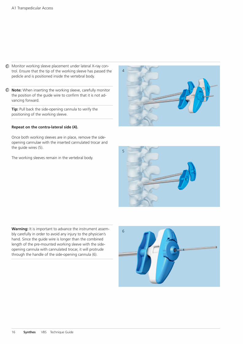
Monitor working sleeve placement under lateral X-ray con-trol. Ensure that the tip of the working sleeve has passed thepedicle and is positioned inside the vertebral body.
Note: When inserting the working sleeve, carefully monitorthe position of the guide wire to confirm that it is not ad-vancing forward.
Tip: Pull back the side-opening cannula to verify the positioning of the working sleeve.
Repeat on the contra-lateral side (4).
Once both working sleeves are in place, remove the side-opening cannulae with the inserted cannulated trocar andthe guide wires (5).
The working sleeves remain in the vertebral body.
Warning: It is important to advance the instrument assem-bly carefully in order to avoid any injury to the physician’shand. Since the guide wire is longer than the combinedlength of the pre-mounted working sleeve with the side-opening cannula with cannulated trocar, it will protrudethrough the handle of the side-opening cannula (6).
A1 Transpedicular Access
A2 Extra-/Parapedicular Access
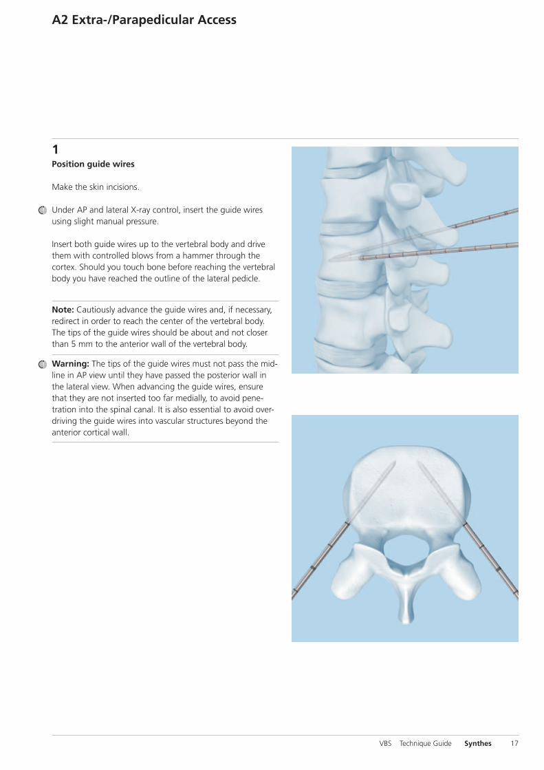
1Position guide wires
Make the skin incisions.
Under AP and lateral X-ray control, insert the guide wires using slight manual pressure.
Insert both guide wires up to the vertebral body and drivethem with controlled blows from a hammer through the cortex. Should you touch bone before reaching the vertebralbody you have reached the outline of the lateral pedicle.
Note: Cautiously advance the guide wires and, if necessary,redirect in order to reach the center of the vertebral body.The tips of the guide wires should be about and not closerthan 5 mm to the anterior wall of the vertebral body.
Warning: The tips of the guide wires must not pass the mid-line in AP view until they have passed the posterior wall inthe lateral view. When advancing the guide wires, ensurethat they are not inserted too far medially, to avoid pene -tration into the spinal canal. It is also essential to avoid over-driving the guide wires into vascular structures beyond theanterior cortical wall.
VBS Technique Guide Synthes 17
1
2
3
18 Synthes VBS Technique Guide
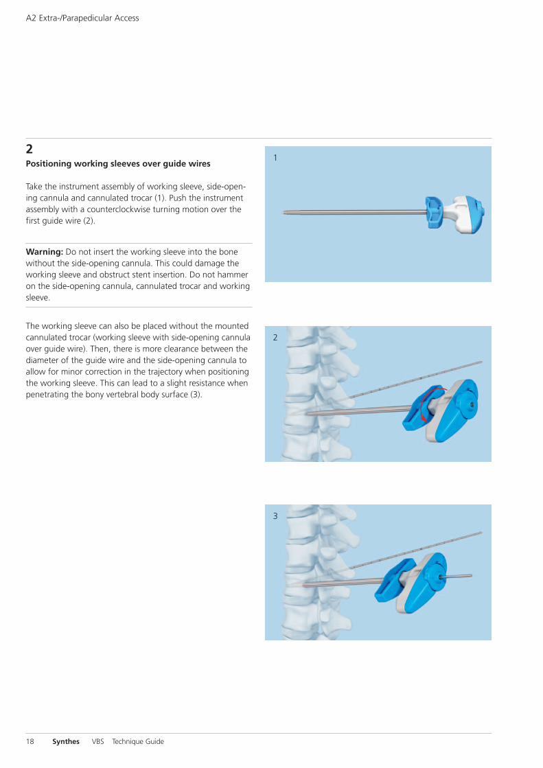
2Positioning working sleeves over guide wires
Take the instrument assembly of working sleeve, side-open-ing cannula and cannulated trocar (1). Push the instrumentassembly with a counterclockwise turning motion over thefirst guide wire (2).
Warning: Do not insert the working sleeve into the bonewithout the side-opening cannula. This could damage theworking sleeve and obstruct stent insertion. Do not hammeron the side-opening cannula, cannulated trocar and workingsleeve.
The working sleeve can also be placed without the mountedcannulated trocar (working sleeve with side-opening cannulaover guide wire). Then, there is more clearance between thediameter of the guide wire and the side-opening cannula toallow for minor correction in the trajectory when positioningthe working sleeve. This can lead to a slight resistance whenpenetrating the bony vertebral body surface (3).
A2 Extra-/Parapedicular Access

4
5
6
Monitor working sleeve placement under lateral X-ray con-trol. Advance the tip of the working sleeve until it has pene-trated the cortex and is tightly seated into the bone.
Note: When inserting the working sleeve, carefully monitorthe position of the guide wire to confirm that it is not ad-vancing forward.
Tip: Pull back the side-opening cannula to verify the positioning of the working sleeve.
Repeat on the contra-lateral side (4).
Once both working sleeves are in place, remove the side-opening cannulae with the inserted cannulated trocar andthe guide wires (5).
The working sleeves remain in the vertebral body.
Warning: It is important to advance the instrument assem-bly carefully in order to avoid any injury to the physician’shand. The guide wire is longer than the combined length ofthe instrument assembly of working sleeve and the side-opening cannula and cannulated trocar will protrudethrough the handle of the side-opening cannula (6).
VBS Technique Guide Synthes 19

20 Synthes VBS Technique Guide
Instrument PositioningB With Trocars
Instrument Set
03.804.512S Vertebral Body Stent Access Kit
When using trocars for instrument positioning, creating thepathway and positioning of the instrumentation is achievedin one step.
Either a transpedicular or extra-/parapedicular access may beselected depending on the anatomy of the vertebral body to be treated.
Note: With either access technique it is important to plan toplace the two stents symmetrically towards the midline.
1
3
2
B1 Transpedicular Access
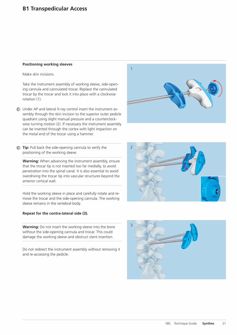
Positioning working sleeves
Make skin incisions.
Take the instrument assembly of working sleeve, side-open-ing cannula and cannulated trocar. Replace the cannulatedtrocar by the trocar and lock it into place with a clockwise rotation (1).
Under AP and lateral X-ray control insert the instrument as-sembly through the skin incision to the superior outer pediclequadrant using slight manual pressure and a counterclock-wise turning motion (2). If necessary the instrument assemblycan be inserted through the cortex with light impaction onthe metal end of the trocar using a hammer.
Tip: Pull back the side-opening cannula to verify the positioning of the working sleeve.
Warning: When advancing the instrument assembly, ensurethat the trocar tip is not inserted too far medially, to avoidpenetration into the spinal canal. It is also essential to avoidoverdriving the trocar tip into vascular structures beyond theanterior cortical wall.
Hold the working sleeve in place and carefully rotate and re-move the trocar and the side-opening cannula. The workingsleeve remains in the vertebral body.
Repeat for the contra-lateral side (3).
Warning: Do not insert the working sleeve into the bonewithout the side-opening cannula and trocar. This coulddamage the working sleeve and obstruct stent insertion.
Do not redirect the instrument assembly without removing itand re-accessing the pedicle.
VBS Technique Guide Synthes 21
1
3
2
22 Synthes VBS Technique Guide
B2 Extra-/Parapedicular Access
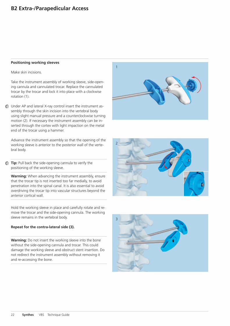
Positioning working sleeves
Make skin incisions.
Take the instrument assembly of working sleeve, side-open-ing cannula and cannulated trocar. Replace the cannulatedtrocar by the trocar and lock it into place with a clockwise rotation (1).
Under AP and lateral X-ray control insert the instrument as-sembly through the skin incision into the vertebral body using slight manual pressure and a counterclockwise turningmotion (2). If necessary the instrument assembly can be in-serted through the cortex with light impaction on the metalend of the trocar using a hammer.
Advance the instrument assembly so that the opening of theworking sleeve is anterior to the posterior wall of the verte-bral body.
Tip: Pull back the side-opening cannula to verify the positioning of the working sleeve.
Warning: When advancing the instrument assembly, ensurethat the trocar tip is not inserted too far medially, to avoidpenetration into the spinal canal. It is also essential to avoidoverdriving the trocar tip into vascular structures beyond theanterior cortical wall.
Hold the working sleeve in place and carefully rotate and re-move the trocar and the side-opening cannula. The workingsleeve remains in the vertebral body.
Repeat for the contra-lateral side (3).
Warning: Do not insert the working sleeve into the bonewithout the side-opening cannula and trocar. This coulddamage the working sleeve and obstruct stent insertion. Donot redirect the instrument assembly without removing itand re-accessing the bone.

1
2
Create Access Channel
Instrument Set
03.804.512S Vertebral Body Stent Access Kit
Guide the drill (1) and afterwards the blunt plunger (2)through the working sleeves to create an access channel forthe stents.
Warning: Use lateral X-ray intensification to avoid penetrat-ing the anterior cortex of the vertebral body. It is essential toavoid overdriving these instruments into vascular structuresbeyond the anterior cortical wall.
Warning: Do not use a hammer to drive the drill forward.The drill may aggressively advance with rotation.
The plunger can be driven forward with light hammer blows.Ensure that the hammer blows hit the protruding metal pinand not the plastic handle (2).
Warning: While using drill or plunger, it is important to en-sure that the working sleeves do not move. Do not usethe drill or plunger to manipulate or correct the direction ofthe working sleeve.
Repeat on the contra-lateral side.
VBS Technique Guide Synthes 23
1
24 Synthes VBS Technique Guide
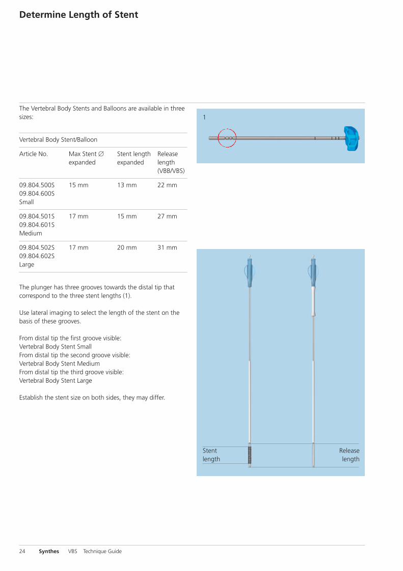
The Vertebral Body Stents and Balloons are available in threesizes:
Vertebral Body Stent/Balloon
Article No. Max Stent � Stent length Release expanded expanded length (VBB/VBS)
09.804.500S 15 mm 13 mm 22 mm09.804.600SSmall
09.804.501S 17 mm 15 mm 27 mm09.804.601SMedium
09.804.502S 17 mm 20 mm 31 mm09.804.602SLarge
The plunger has three grooves towards the distal tip that correspond to the three stent lengths (1).
Use lateral imaging to select the length of the stent on thebasis of these grooves.
From distal tip the first groove visible: Vertebral Body Stent SmallFrom distal tip the second groove visible: Vertebral Body Stent MediumFrom distal tip the third groove visible: Vertebral Body Stent Large
Establish the stent size on both sides, they may differ.
Determine Length of Stent
Releaselength
Stentlength

1 2If you do not intend to use the VBB please continue topage 34 chapter “Using the VBS”.
The VBS System can optionally be used with a Vertebral BodyBalloon (VBB). The VBB allows simulating the stent expansionwhen bone quality, age of the fracture or the fracture / lesionmobility of the vertebral body is unknown.
1Unpacking the VBB Catheter
Remove the VBB catheter from the sterile packaging (1).
Note: Slide back the white cover sleeve towards the Luerconnector and attach it properly to the luer (2). This coversleeve can be used later for stretching and folding back theVBB after catheter removal for reuse.
Do not remove the stiffening wire from the VBB catheter.The stiffening wire will be removed and the creation of thevacuum will be performed after the insertion of the VBBcatheter on the patient. This is different compared to theVBS catheter insertion.
There is a white marking range on the balloon catheter shaftindicating release length, i.e. the overall length and bothproximal and distal balloon shoulders segments when thewhite marking range is completely inserted into the workingsleeve.
The VBB can be reused once within one surgery.
Warning: Only use the VBB of same size together with thecorresponding VBS.
Note: The shaft marker indicates when balloon is fully inserted, use X-ray while inflating with contrast media.
Optional: Use of VBB
VB Balloon
Stiffening wire
White coversleeve
VBS Technique Guide Synthes 25
1
26 Synthes VBS Technique Guide
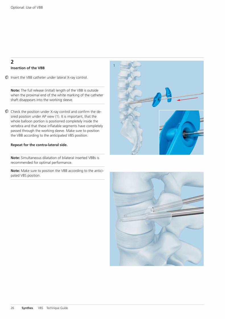
2Insertion of the VBB
Insert the VBB catheter under lateral X-ray control.
Note: The full release (initial) length of the VBB is outsidewhen the proximal end of the white marking of the cathetershaft disappears into the working sleeve.
Check the position under X-ray control and confirm the de-sired position under AP view (1). It is important, that thewhole balloon portion is positioned completely inside thevertebra and that these inflatable segments have completelypassed through the working sleeve. Make sure to positionthe VBB according to the anticipated VBS position.
Repeat for the contra-lateral side.
Note: Simultaneous dilatation of bilateral inserted VBBs isrecommended for optimal performance.
Note: Make sure to position the VBB according to the antici-pated VBS position.
Optional: Use of VBB
2
1
J
K
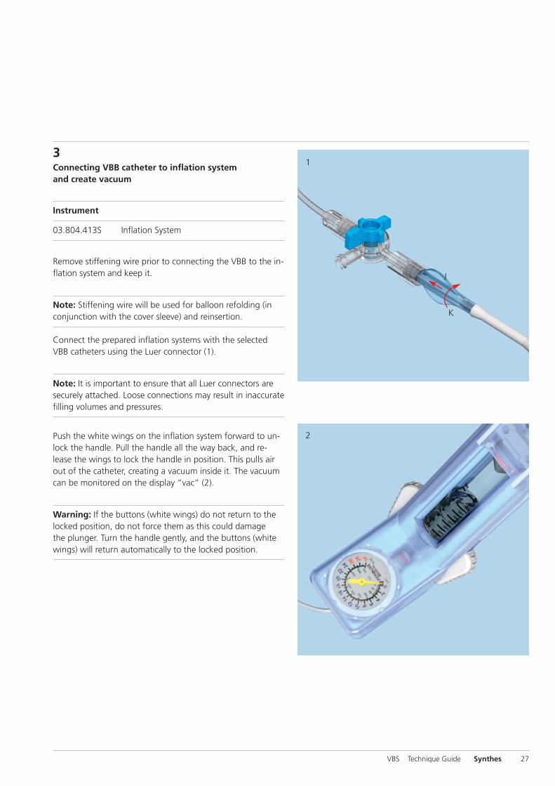
3Connecting VBB catheter to inflation systemand create vacuum
Instrument
03.804.413S Inflation System
Remove stiffening wire prior to connecting the VBB to the in-flation system and keep it.
Note: Stiffening wire will be used for balloon refolding (inconjunction with the cover sleeve) and reinsertion.
Connect the prepared inflation systems with the selectedVBB catheters using the Luer connector (1).
Note: It is important to ensure that all Luer connectors aresecurely attached. Loose connections may result in inaccuratefilling volumes and pressures.
Push the white wings on the inflation system forward to un-lock the handle. Pull the handle all the way back, and re-lease the wings to lock the handle in position. This pulls airout of the catheter, creating a vacuum inside it. The vacuumcan be monitored on the display “vac” (2).
Warning: If the buttons (white wings) do not return to thelocked position, do not force them as this could damage the plunger. Turn the handle gently, and the buttons (whitewings) will return automatically to the locked position.
VBS Technique Guide Synthes 27
3
4
28 Synthes VBS Technique Guide
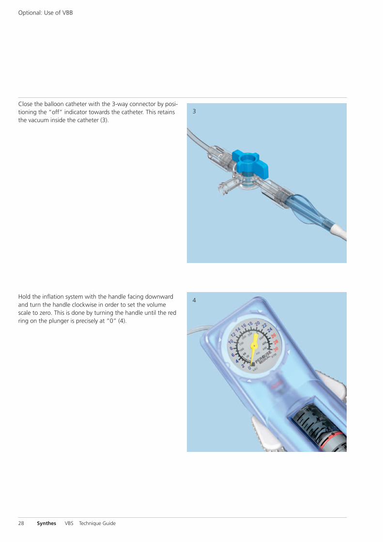
Close the balloon catheter with the 3-way connector by posi-tioning the “off” indicator towards the catheter. This retainsthe vacuum inside the catheter (3).
Optional: Use of VBB
Hold the inflation system with the handle facing downwardand turn the handle clockwise in order to set the volumescale to zero. This is done by turning the handle until the redring on the plunger is precisely at “0” (4).
6
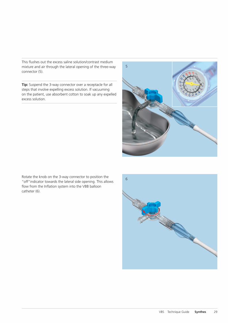
5This flushes out the excess saline solution/contrast mediummixture and air through the lateral opening of the three-wayconnector (5).
Tip: Suspend the 3-way connector over a receptacle for allsteps that involve expelling excess solution. If vacuumingon the patient, use absorbent cotton to soak up any expelledexcess solution.
VBS Technique Guide Synthes 29
Rotate the knob on the 3-way connector to position the“off”indicator towards the lateral side opening. This allowsflow from the Inflation system into the VBB ballooncatheter (6).

2
30 Synthes VBS Technique Guide
Inflation of VBB
1Inflation of VBB
Note: Simultaneous dilatation of bilateral devices is recom-mended for optimal performance.
Warning: It is essential to use AP and lateral X-rays to trackVBB expansion via the balloon contrast media solution infla-tion fluid.
Slowly increase pressure and volume by rotating the handlesof the connected inflation systems in a clockwise directionon both sides.
Proceed slowly after each VBB balloon unfolds and starts expanding at approx. 12 atm (2). Match the expansion bi -laterally by tracking the fluid volume on the syringe bodywith the black volume markers positioned in ml increments.When the pressure reaches and increases beyond 26 atm,continue dilatation gradually. Wait a few seconds then slowlycontinue until the desired VBB diameter is reached (3). Themaximum stent diameter is 15 mm for VBB Small and 17mm for both VBB Medium and VBB Large.
Stop balloon expansion when any of the following happens:1. Desired vertebral body height or angle is reached 2. Pressure reaches 30 atm (400 PSI)3. VBB volume reaches maximum
– 4.0 ml for VBB Small – 4.5 ml for VBB Medium – 5.0 ml for VBB Large
Note: The VBB expansion pressure and volume on the infla-tion system have to be monitored carefully on the inflationsystem’s phosphorescent manometer (units: bar/atm, PSI)and syringe body with black volume markers (units: ml/cc),respectively.

1
2
Warning: Do not fill the balloons over their maximum vol-ume or pressure. If this is done, they may leak.
Warning: VBB maximum volumes differ from VBS maximumvolumes!
Note: In case of contrast medium leakage, pull vacuum, in-sert stiffening wire and remove balloon, don't reuse balloon.
2Retrieve balloon catheters
Slowly turn the handles of the inflation systems counter-clockwise to draw the liquid out of the balloon catheter (1).Once the pressure has reached 10 atm, push the white wingsforward, slowly pull the handle back all the way, and releasethe white wings (2). This draws and holds a vacuum in thecatheter.
VBS Technique Guide Synthes 31

1
2
32 Synthes VBS Technique Guide
Inflation of VBB
Aerate the VBB catheter by first positioning the “off” indica-tor towards the catheter (1) and second turn back towardsthe lateral side opening (1 inset).
Disconnect the inflation system from the VBB catheter.
Note: Carefully insert the stiffening wire into the VBBcatheter under X-ray control.
Apply a gentle force in order to stretch the deflated balloonprior to removal of the catheter (2). Make sure not to dam-age the VBB catheter by pushing too hard.
Hold the working sleeves in place and pull carefully on thecatheters to retrieve the balloons. Rotate the catheters ifneeded to ease balloon removal.
Note: The VBB catheter can be re-used once within one sur-gery. Make sure by visual inspection that the VBB catheterhas not been damaged.
Warning: do not use a VBB catheter when a visual damageis observed, or when a leak is evident.
Warning: If balloon-catheter material is remaining in verte-bral body after removal of the VBB do not leave it implanted.The balloon-catheter material is not implant grade material.
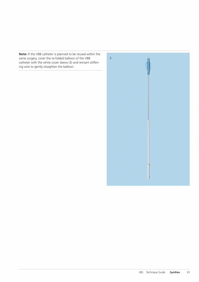
3Note: If the VBB catheter is planned to be reused within thesame surgery, cover the re-folded balloon of the VBBcatheter with the white cover sleeve (3) and reinsert stiffen-ing wire to gently straighten the balloon.
VBS Technique Guide Synthes 33
VB Stent
Stiffening wire
34 Synthes VBS Technique Guide
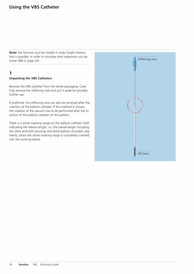
Note: the fracture must be mobile in order height restora-tion is possible. In order to simulate stent expansion use op-tional VBB (s. page 25)
1Unpacking the VBS Catheters
Remove the VBS catheter from the sterile packaging. Care-fully remove the stiffening wire and put it aside for possiblefurther use.
If preferred, the stiffening wire can also be removed after theinsertion of the balloon catheter. If this method is chosen,the creation of the vacuum has to be performed after the in-sertion of the balloon catheter on the patient.
There is a white marking range on the balloon catheter shaftindicating the release length, i.e. the overall length includingthe stent and both proximal and distal balloon shoulders seg-ments, when the white marking range is completely insertedinto the working sleeve.
Using the VBS Catheter
2
1
J
K
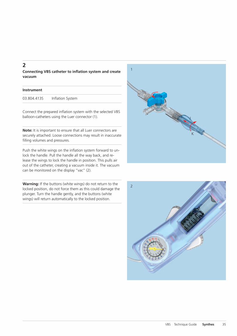
2Connecting VBS catheter to inflation system and createvacuum
Instrument
03.804.413S Inflation System
Connect the prepared inflation system with the selected VBSballoon-catheters using the Luer connector (1).
Note: It is important to ensure that all Luer connectors aresecurely attached. Loose connections may result in inaccuratefilling volumes and pressures.
Push the white wings on the inflation system forward to un-lock the handle. Pull the handle all the way back, and re-lease the wings to lock the handle in position. This pulls airout of the catheter, creating a vacuum inside it. The vacuumcan be monitored on the display “vac” (2).
Warning: If the buttons (white wings) do not return to thelocked position, do not force them as this could damage theplunger. Turn the handle gently, and the buttons (whitewings) will return automatically to the locked position.
VBS Technique Guide Synthes 35
3
4
36 Synthes VBS Technique Guide
Using the VBS Catheter
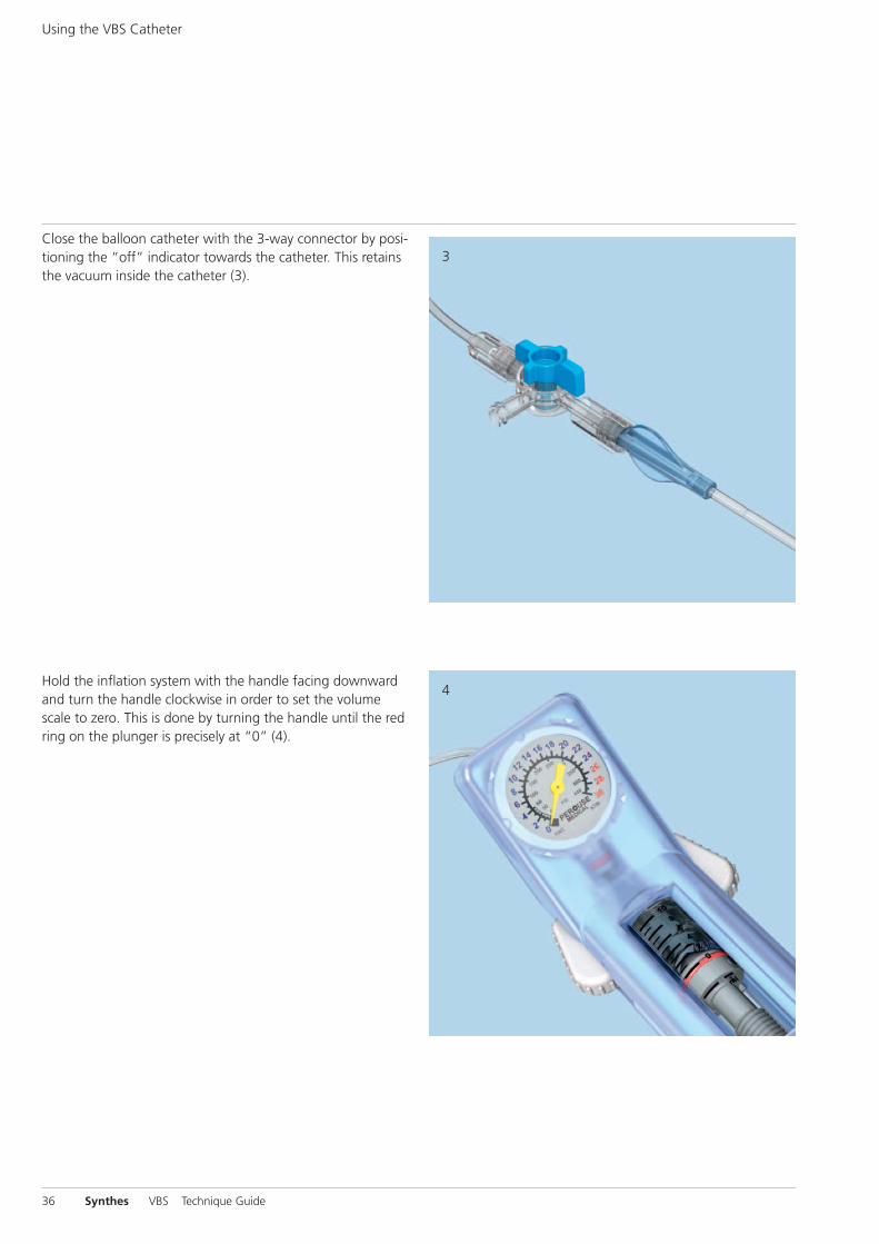
Close the balloon catheter with the 3-way connector by posi-tioning the “off” indicator towards the catheter. This retainsthe vacuum inside the catheter (3).
Hold the inflation system with the handle facing downwardand turn the handle clockwise in order to set the volumescale to zero. This is done by turning the handle until the redring on the plunger is precisely at “0” (4).
5
6
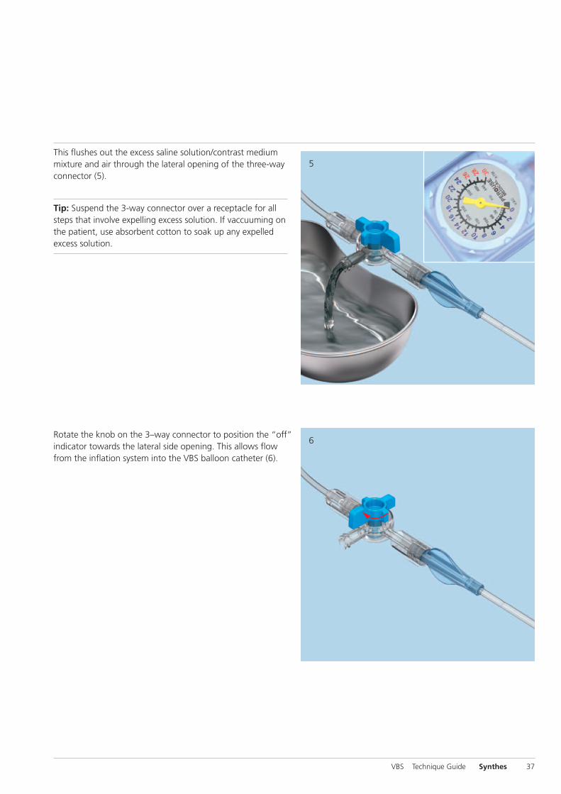
This flushes out the excess saline solution/contrast mediummixture and air through the lateral opening of the three-wayconnector (5).
Tip: Suspend the 3-way connector over a receptacle for allsteps that involve expelling excess solution. If vaccuuming onthe patient, use absorbent cotton to soak up any expelledexcess solution.
Rotate the knob on the 3–way connector to position the “off”indicator towards the lateral side opening. This allows flowfrom the inflation system into the VBS balloon catheter (6).
VBS Technique Guide Synthes 37

1
38 Synthes VBS Technique Guide
Deployment of Stents
1Insert and deploy stentsInsert the balloon catheter with the attached stent under lateral X-ray control. The full release (initial) length of the bal-loon with stent is outside the working sleeve when the proxi-mal end of the white marking of the catheter shaft disap-pears into the working sleeve. Check the position underX-ray control and confirm the desired position under APview (1). It is important, that the whole balloon portion in-cluding the stent is positioned completely inside the vertebraand that these parts have completely passed through theworking sleeve.
Repeat on the contra-lateral side.
Note: Simultaneous dilatation of bilateral devices is essentialfor optimal device performance. Once stent expansion hasbegun the stent cannot be undeployed or repositioned.
Warning: It is essential to use AP and lateral X-rays to trackstent expansion and balloon shoulder inflation via the radiopacity due to the stent and the balloon contrast mediasolution inflation fluid, respectively.
Slowly increase pressure and volume by rotating the handlesof the connected inflation system in a clockwise direction onboth sides.

2
3
Proceed slowly after the stents begin expanding at approx.12 atm (2). Match the expansion bilaterally by tracking thefluid volume on the scales. When the pressure reaches 26 atm, continue dilatation gradually. Wait a few secondsthen slowly continue until the desired stent diameter isreached (3). The maximum stent diameter is 15 mm for VBSSmall and 17 mm for both VBS Medium and VBS Large.
Stop balloon inflation when any of the following happens:1. Desired vertebral body height or angle is reached 2. Pressure reaches 30 atm 3. VBS volume reaches maximum
– 4.5 ml for VBS Small – 5.0 ml for VBS Medium – 5.5 ml for VBS Large
Note: The VBS expansion pressure and volume on the infla-tion System have to be monitored carefully on the inflationsystem’s phosphorescent manometer (units: bar/atm, PSI)and syringe body with black volume markers (units: ml/cc),respectively.
Warning: Do not inflate the balloons beyond their maxi-mum volume or pressure. If this is done, they may leak.
Warning: VBS maximum volumes differ from VBB maximumvolumes.
Once the expansion is stopped, record the volume of solu-tion used indicated on the inflation system.
VBS Technique Guide Synthes 39
1
2
40 Synthes VBS Technique Guide
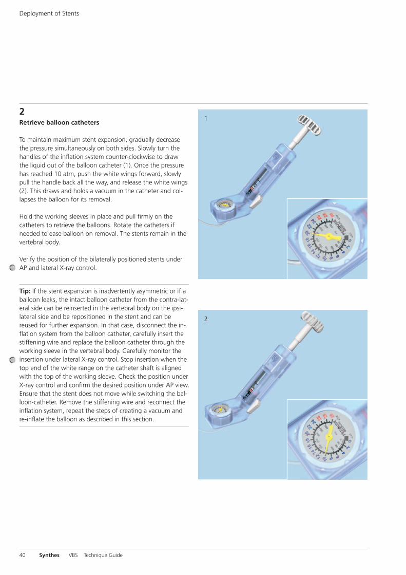
2Retrieve balloon catheters To maintain maximum stent expansion, gradually decreasethe pressure simultaneously on both sides. Slowly turn thehandles of the inflation system counter-clockwise to drawthe liquid out of the balloon catheter (1). Once the pressurehas reached 10 atm, push the white wings forward, slowlypull the handle back all the way, and release the white wings(2). This draws and holds a vacuum in the catheter and col-lapses the balloon for its removal.
Hold the working sleeves in place and pull firmly on thecatheters to retrieve the balloons. Rotate the catheters ifneeded to ease balloon on removal. The stents remain in thevertebral body.
Verify the position of the bilaterally positioned stents underAP and lateral X-ray control.
Tip: If the stent expansion is inadvertently asymmetric or if aballoon leaks, the intact balloon catheter from the contra-lat-eral side can be reinserted in the vertebral body on the ipsi-lateral side and be repositioned in the stent and can bereused for further expansion. In that case, disconnect the in-flation system from the balloon catheter, carefully insert thestiffening wire and replace the balloon catheter through theworking sleeve in the vertebral body. Carefully monitor theinsertion under lateral X-ray control. Stop insertion when thetop end of the white range on the catheter shaft is alignedwith the top of the working sleeve. Check the position underX-ray control and confirm the desired position under AP view.Ensure that the stent does not move while switching the bal-loon-catheter. Remove the stiffening wire and reconnect theinflation system, repeat the steps of creating a vacuum andre-inflate the balloon as described in this section.
Deployment of Stents
Note: If the contrast medium/saline solution mixture leakswhen the stents are expanded, it may be more difficult to re-move the balloon catheters through the working sleeves. Ifnecessary remove the balloon catheters together with theworking sleeves or insert the stiffening wire for removal.
Warning: If balloon material is remaining in vertebral bodyafter removal of the VBS balloon do not leave it implanted.The balloon material is not implant grade material.
VBS Technique Guide Synthes 41
1
2
42 Synthes VBS Technique Guide
Cement Augmentation
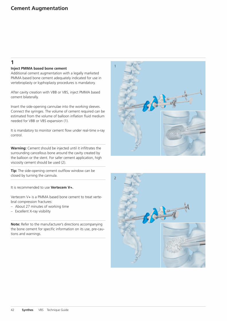
1Inject PMMA based bone cementAdditional cement augmentation with a legally marketedPMMA based bone cement adequately indicated for use invertebroplasty or kyphoplasty procedures is mandatory.
After cavity creation with VBB or VBS, inject PMMA basedcement bilaterally.
Insert the side-opening cannulae into the working sleeves.Connect the syringes. The volume of cement required can beestimated from the volume of balloon inflation fluid mediumneeded for VBB or VBS expansion (1).
It is mandatory to monitor cement flow under real-time x-raycontrol.
Warning: Cement should be injected until it infiltrates thesurrounding cancellous bone around the cavity created bythe balloon or the stent. For safer cement application, highviscosity cement should be used (2).
Tip: The side-opening cement outflow window can beclosed by turning the cannula.
It is recommended to use Vertecem V+.
Vertecem V+ is a PMMA based bone cement to treat verte-bral compression fractures:– About 27 minutes of working time – Excellent X-ray visibility
Note: Refer to the manufacturer’s directions accompanyingthe bone cement for specific information on its use, pre-cau-tions and warnings.

2Remove side-opening needles and working sleevesWait until the cement has fully hardened. Observe the bonecement manufacturer’s instructions as the hardening timesfor PMMA based cements can greatly vary.
Usually instruments used for the cement injection shall be re-moved after hardening of PMMA based bone cement bytwisting the instrument assembly several times to sever thecement bridge.
Suture the wound with tight stitches for hemostasis.
VBS Technique Guide Synthes 43
Postoperative procedureTo compress the wound the patient should be placed in asupine position for an hour after surgery. Bruising may occurat the puncture sites. The patient can then be mobilized atdiscretion.

44 Synthes VBS Technique Guide
Implants and Balloon-Catheters
Vertebral Body Stent
09.804.500S 09.804.501S 09.804.502S VBS Small VBS Medium VBS Large
Release 22 mm 27 mm 31 mm(initial)length
Stent 13 mm 15 mm 20 mmlengthexpanded
Max � 15 mm 17 mm 17 mmexpanded
Max 4.5 ml 5.0 ml 5.5 mlvolume
Max 30 bar 30 bar 30 barpressure
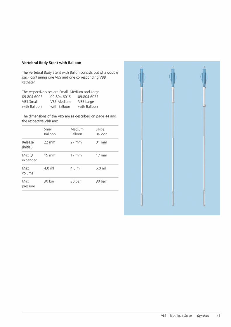
Vertebral Body Stent with Balloon
The Vertebral Body Stent with Ballon consists out of a doublepack containing one VBS and one corresponding VBBcatheter.
The respective sizes are Small, Medium and Large:09.804.600S 09.804.601S 09.804.602SVBS Small VBS Medium VBS Large with Balloon with Balloon with Balloon
The dimensions of the VBS are as described on page 44 andthe respective VBB are:
Small Medium Large Balloon Balloon Balloon
Release 22 mm 27 mm 31 mm(initial)
Max � 15 mm 17 mm 17 mmexpanded
Max 4.0 ml 4.5 ml 5.0 mlvolume
Max 30 bar 30 bar 30 barpressure
VBS Technique Guide Synthes 45
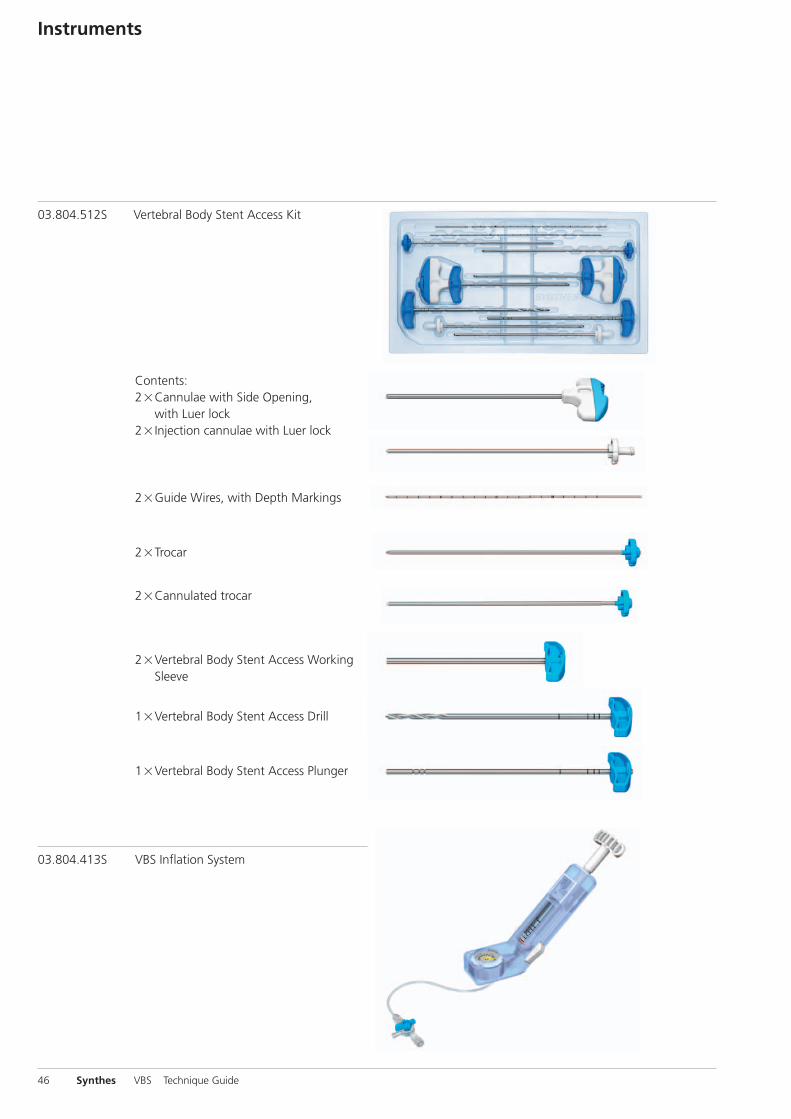
Contents: 2�Cannulae with Side Opening,
with Luer lock 2�Injection cannulae with Luer lock
46 Synthes VBS Technique Guide
Instruments
03.804.512S Vertebral Body Stent Access Kit
03.804.413S VBS Inflation System
2�Guide Wires, with Depth Markings
2�Trocar
2�Cannulated trocar
2�Vertebral Body Stent Access WorkingSleeve
1�Vertebral Body Stent Access Drill
1�Vertebral Body Stent Access Plunger

Optional Instruments
399.410 Hammer, 300 g
Vertecem V+ System
07.702.016S Vertecem V+ Cement Kit Containing: 1�Vertecem V+ Mixer pre-filled with
cement powder 1�Monomer glass ampoule
03.702.215S Vertecem V+ Syringe Kit Containing: 8�Blue 1 ml syringes 5�White 2 ml syringes 1�one-way stop cock
292.210S Kirschner Wire � 2.0 mm with trocar tip,length 280 mm, Stainless Steel, sterile
VBS Technique Guide Synthes 47
48 Synthes VBS Technique Guide
Bibliography
Atalay B, Caner H, Gokce C, Altinors N (2005) Kyphoplasty:2 years of experience in a neurosurgery department. SurgicalNeurology 64: S2:72–S2:76
Belkoff T, Jasper LE, Stevens SS (1999) An Ex Vivo Evaluationof an Inflatable Bone Tamp Used to Reduce Fractures WithinVertebral Bodies Under Load. Spine 27(15): 1640–1643
Berlemann U, Heini PF (2002) Percutaneous cementing tech-niques in treatment of osteoporotic spinal sintering. Unfall -chirurg 105(1):2– 8
Berlemann U, Muller CW, Krettek C (2004) Percutaneous cementing techniques of the spine – chances and limits. Orthopäde 33(1):6 –12
Berlis A (2007) Conservative and minimally invasive treatment modalities at the spine. Med Monatsschr Pharm30(1):17–24
Blondel B, Fuentes S, Metellus P, Adetchessi T, Pech-Gourg G,Dufour H (2009) Severe thoracolumbar osteoporotic burstfractures: Treatment combining open kyphoplasty and short-segment fixation. Orthopaedics & Traumatology: Surgery &Research 95(5):359 –364
Boszczyk B, Bierschneider M, Potulski M, Robert B, VastmansJ, Jaksche H (2002) Extended kyphoplasty indications for stabilization of osteoporotic vertebral compression fractures.Unfallchirurg 105(10):952–7
Boulay C, Tardieu C, Hecquet J, et al. (2006) Sagittal align-ment of spine and pelvis regulated by pelvic incidence: stan-dard values and prediction of lordosis. Eur Spine J 15:415–22
Bouza C, López T, Magro A, Navalpotro L, Amate JM (2006)Efficacy and safety of balloon Kyphoplasty in the treatmentof vertebral compression fractures: a systematic review. Eur Spine J 15(7):1050 –1067
Cloft HJ, Jensen ME (2007) Kyphoplasty: an assessment of anew technology. AJNR Am J Neuroradiol. 28(2):200 –3
Eck JC, Nachtigall D, Humphreys SC, Hodges SD (2008)Comparison of vertebroplasty and balloon kyphoplasty fortreatment of vertebral compression fractures: a meta-analysisof the literature. The Spine Journal 8:488 – 497
Erickson K, Baker S, Smith J, (2003) Kyphoplasty-minimallyinvasive vertebral compression fracture repair. AORN J78(5):766 –73;quiz 777– 80
De Falco R, Scarano E, Di Celmo D, Grasso U, Guarnieri L(2005) Balloon kyphoplasty in traumatic fractures of the thoracolumbar junction: Preliminary experience in 12 cases. J Neurosurg Sci 49:147–153
Fribourg D, Tang C, Sra P, Delamarter R, Bae H (2004) Incidence of subsequent vertebral fracture after kyphoplasty.Spine 29(20):2270–6; discussion 2277
Fürderer S, Anders M, Schwindling B, Salick M, Düber C,Wenda K, Urban R, Glück M, Eysel P (2002) Vertebral bodystenting. A method for repositioning and augmenting verte-bral body compression fractures. Orthopäde 31:356 –361
Garfin SR, Yuan HA, Reiley MA (2001) New technologies inspine: kyphoplasty and vertebroplasty for the treatment of painful osteoporotic compression fractures. Spine26(14):1511– 5
Genant HK, Wu CY, Van Kuijk C, Nevitt MC (1993) VertebralFracture Assessment Using a Semiquantitative Method. JBone Miner Res 8(9):1137–1148
Gerszten PC, Welch WC (2007). Combined percutaneoustranspedicular tumor debulking and kyphoplasty for patho-logical compression fractures. Technical note J NeurosurgSpine 6(1):92–5
Grafe IA, Da Fonseca K, Hillmeier J, Meeder PJ, Libicher M,Nöldge G, Bardenheuer H, Pyerin W, Basler L, Weiss C, TaylorRS, Nawroth P, Kasperk C (2005) Reduction of pain and frac-ture incidence after kyphoplasty:1-year outcomes of aprospective controlled trial of patientswith primary osteo-porosis. Osteoporos Int. 16(12):2005 –12
Heini PF (2005) The current treatment–a survey of osteo-porotic fracture treatment. Osteoporotic spine fractures: thespine surgeon’s perspective. Osteoporos Int. 16 Suppl 2:S85–92
Heini PF (2010) Vertebroplastie: ein Update. Orthopäde39:658–664
Hulme PA, Krebs J, Ferguson SJ, Berlemann U (2006) Verte-broplasty and kyphoplasty: a systematic review of 69 clinicalstudies. Spine 31(17):1983–2001
Krepler P, Grohs JG (2003) Minimally invasive therapy ofpainful osteoporotic vertebral fractures. Radiologe 43(9):718 –22
Lieberman IH, Dudeney S, Reinhardt MK, Bell G (2001) Initialoutcome and efficacy of ”kyphoplasty” in the treatment ofpainful osteoporotic vertebral compression fractures. Spine15 26(14):1631– 8
Magerl F, Aebi M, Gertzbein SD, Harms J, Nazarian S (1994)A comprehensive classification of thoracic and lumbar in-juries. Eur Spine J 3:184-201
Masala S, Cesaroni A, Sergiacomi G, Fiori R, Massari F, Ma-nenti G, Nardi P, Simonetti G (2004) Percutaneous kypho-plasty: new treatment for painful vertebral body fractures. In Vivo 18(2):149 –53
McGirt MJ, Parker SL, Wolinsky JP, Witham TF, Bydon A,Gokaslan ZL (2009) Vertebroplasty and kyphoplasty for thetreatment of vertebral compression fractures: an evidenced-based review of the literature. The Spine Journal 9:501–508
Meeder PJ, Da Fonseca K, Hillmeier J, Grafe I, Noeldge G,Kasperk C (2003) Kyphoplasty and vertebroplasty in fracturesin the elderly: effort and effect. Chirurg 74(11):994 – 9
Mendel E, Bourekas E, Gerszten P, Golan JD (2009) Percuta-neous Techniques in the Treatment of Spine Tumors. Spine34(22S):S93–S100
Nöldge G, DaFonseca K, Grafe I, Libicher M, Hillmeier J,Meeder PJ, Kauffmann GW, Kasperk C (2006) Balloonkyphoplasty in the treatment of back pain. Radiologe 46(6):506 –12
Ohlin A, Johnell O (2004) Vertebroplasty and kyphoplasty inthe fractured osteoporotic spine. Clin Calcium 14(1):65 – 9
Rotter R, Martin H, Fuerderer S, Gabl M, Roeder C, Heini P,Mittlmeier T (2010) Vertebral body stenting: a new methodfor vertebral augmentation versus kyphoplasty. Eur Spine J19:916 –923
Sato K, Kikuchi S, Yonezawa T (1999) In Vivo Intradiscal Pres-sure Measurement in Healthy Individuals and in Patients WithOngoing Back Problems. Spine 24(23): 2468–2474
Taylor RS, Taylor RJ, Fritzell P (2006) Balloon Kyphoplasty andVertebroplasty for Vertebral Compression Fractures: A Com-parative Systematic Review of Efficacy and Safety. Spine31(23):2747–2755
Taylor RS, Fritzell P, Taylor RJ (2007) Balloon kyphoplasty inthe management of vertebral compression fractures: an updated systematic review and meta-analysis. Eur Spine J16:1085 –1100
Voggenreiter G (2005) Balloon kyphoplasty is effective in deformity correction of osteoporotic vertebral compressionfractures. Spine 30(24):2806 –12
Wardlaw D, Cummings SR, Van Meirhaeghe J, Bastian L, Till-man JB, Ranstam J, Eastell R, Shabe P, Talmadge K, Boonen S(2009) Efficacy and safety of balloon kyphoplasty comparedwith non-surgical care for vertebral compression fracture(FREE): a randomised controlled trial. Lancet 373:1016 –24
Watts NB, Harris ST, Genant HK (2001) Treatment of painfulosteoporotic vertebral fractures with percutaneous vertebro-plasty or kyphoplasty. Osteoporos Int. 12(6):429 –37
Wilhelm K, Stoffel M, Ringel F, Rao G, Rosseler L, Urbach H,Meyer B (2003) Preliminary experience with balloon kypho-plasty for the treatment of painful osteoporotic compressionfractures. Rofo 175(12):1690 – 6
Wilke HJ, Mehnert U, Claes LE, Bierschneider MM, Jaksche H,Boszczyk BM (2006) Biomechanical evaluation of vertebro-plasty and kyphoplasty with polymethyl methacrylate or -calcium phosphate cement under cyclic loading. Spine31(25):2934–41
Wilke T, Neef P, Caimi M, Hoogland T, Claes LE (1999) NewIn Vivo Measurements of Pressures in the Intervertebral Discin Daily Life. Spine 24(8): 755–762
Yang HL, Zhao L, Liu J, Sanford CG, Chen L, Tang T, Ebra-heim NA (2007) Changes of pulmonary function for patientswith osteoporotic vertebral compression fractures afterkyphoplasty. J Spinal Disord Tech 20(3):221–225
Zampini JM, White AP, McGuire KJ (2010) Comparison of5766 Vertebral Compression Fractures Treated With or With-out Kyphoplasty. Clin Orthop Relat Res 468(7):1773-1780
VBS Technique Guide Synthes 49

0123
Synthes GmbHEimattstrasse 3CH-4436 Oberdorfwww.synthes.com
Ö036.001.172öAAƒä
All technique guides are available as PDF files at www.synthes.com/lit 03
6.00
1.17
2 ve
rsio
n A
A
06/2
011
5014
7442
©
Syn
thes
, Inc
. or
its a
ffili
ates
Su
bjec
t to
mod
ifica
tion
Synt
hes
and
Vert
ecem
are
tra
dem
arks
of
Synt
hes,
Inc.
or
its a
ffili
ates