vb6-vb8 programing tool-manual- en-10-02-2015 · guardmagic 3 1. introduction “guardmagic vb 6-8...
TRANSCRIPT
GuardMagic VB tool - manual v1.20 10-02-2015
2015
GGuuaarrddMMaaggiicc VVBB66--VVBB88 PPrrooggrraammmmiinngg TTooooll
((GGMM22..003366))
UUsseerr MMaannuuaall
GuardMagic www.guardmagic.com
2
Table of contents: 1. INTRODUCTION .......................................................................................................................3 2. PACKAGES .................................................................................................................................3 2.1. STANDARD PACKAGE..............................................................................................................3 2.2. OPTIONAL (order in additional) ..................................................................................................3 2.3. PACKAGE ....................................................................................................................................3 3. OVERWIEV OF MAIN COMPONENTS ................................................................................4 4. SYSTEM REQUIREMENTS .....................................................................................................4 5. NECESSARY INFORMATION FOR MODULE PROGRAMMING ..................................5 5.1. NECESSERY INFORMATION FROM YOUR LOCAL GSM PROVIDER..............................5 5.2. NECESSERY INFORMATION FROM YOUR MONITORING STATION..............................5 5.3. INFORMATION ABOUT MASTER PHONE.............................................................................5 5.4. NECESSERY INFORMATION TO YOUR MONITORING STATION....................................6 5.5. ADDITIONAL NAME..................................................................................................................6 6. MODULE CONNECTION.........................................................................................................7 6.1. DIRECTLY CONNECTION TO PC ............................................................................................7 6.2. CONNECTION TO PC BY USB-COM ADAPTER....................................................................7 7. START THE PROGRAM AND OVERVIEW OF BASIC FORM ........................................8 7.1. START THE PROGRAM .............................................................................................................8 7.2. SERVICE LINE.............................................................................................................................8 7.3. CONTROLS ELEMENTS ............................................................................................................9 7.4. OPERATION BOOKMARKS ......................................................................................................9 8. OPERATION BOOKMARKS DESCRIPTION ....................................................................10 8.1. BASE SETTING .........................................................................................................................10 8.2. EXTERNAL DEVICES ..............................................................................................................11 8.3. OPERATION PARAMETERS ...................................................................................................12 8.4. ABOUT iBUTTON KEY............................................................................................................14 8.5. COMMUNICATION PARAMETERS.......................................................................................15 9. STARTING OPERATION WITH PROGRAM.....................................................................17 10. PROGRAMMING PROCEDURE...........................................................................................18 10.1. SAMPLE OF “BASE SETTING” BOOKMARK.......................................................................18 10.2. SAMPLE OF “EXTERNAL DEVICE” BOOKMARK..............................................................19 10.3. SAMPLE OF “OPERATION PARAMETERS” BOOKMARK ................................................19 10.4. SAMPLE OF “COMMUNICATION PARAMETERS” BOOKMARK....................................20 10.5. ADDITIONAL NOTES...............................................................................................................20 11. WIRING DIAGRAMS OF GuardMagic VB ..........................................................................21 12. APPENDIX 1 - Digital thermometer ID number reading .....................................................22
GuardMagic www.guardmagic.com
3
1. INTRODUCTION “GuardMagic VB 6-8 programming tool” is the special technological complete set
intended for programming and change the setting of GuardMagic VB6 , GuardMagic VB7 , GuardMagic VB8 modules by Personal Computer.
In additional "GuardMagic VB6-VB8 programming tool” utility allows to carry out fuel tank calibration procedure. Fuel tank calibration procedure is carried by Personal Computer (Notebook).
2. PACKAGES
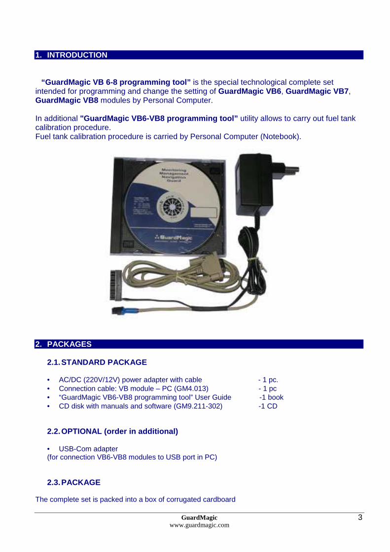
2.1. STANDARD PACKAGE
• AC/DC (220V/12V) power adapter with cable - 1 pc. • Connection cable: VB module – PC (GM4.013) - 1 pc • “GuardMagic VB6-VB8 programming tool” User Guide -1 book • CD disk with manuals and software (GM9.211-302) -1 CD
2.2. OPTIONAL (order in additional)
• USB-Com adapter (for connection VB6-VB8 modules to USB port in PC) 2.3. PACKAGE
The complete set is packed into a box of corrugated cardboard

GuardMagic www.guardmagic.com
4
3. OVERWIEV OF MAIN COMPONENTS
AC/DC (220V/12V) power adapter with cable
Connection cable VB6-VB8 modules – PC (GM4.013) (for connection to: GuardMagic VB6-VB8 modules to PC by RS-232 communication interface
GM
4.01
3
CD disk with manuals and software
CD disk contents: • VB6-VB8 programming software; • “GuardMagic VB6-VB8 programming tool” User
Manual
4. SYSTEM REQUIREMENTS System requirements to the PC:
- MS Windows XP, MS Windows Vista, MS Windows 7; MS Windows 7; - Intel Pentium IV 600 or above (or AMD analogue); - Main memory 256MB or above; - 10 free space on a hard disk; - Mouse and keyboard; - RS-232 port (or USB port*); - Video adapter and color monitor with the resolution not less than 800 x 600; - CD or DVD ROM.
Note: If your PC has only USB interface in additional will be need to use standard USB-Com adapter.
GuardMagic www.guardmagic.com
5
5. NECESSARY INFORMATION FOR MODULE PROGRAMMING
5.1. NECESSERY INFORMATION FROM YOUR LOCAL GSM PROV IDER Before carrying out of the module programming, it is necessary to get information from your GSM operator:
parameters of GPRS at yours GSM the provider , namely:
- access point name/APN - APN server of yours GSM provider; - name (Login)* – user name for access to a server of yours GSM the provider; - password* – password for access to the server of yours GSM the provider;
* - often GSM provider has not (and don’t give) Name and Password to access to its GPRS server. parameters of “SMS” at yours GSM the provider , namely: - SMSC – phone number of GSM provider SMS center (only if you want to receive SMS confirmation from module) This information will be entering in module during programming procedure.
5.2. NECESSERY INFORMATION FROM YOUR MONITORING STATION For the module connection to monitoring station you have to get data from monitoring station (monitoring software), namely:
- IP address of monitoring station (server IP address); - port number of monitoring station server.
If monitoring station (monitoring software) has an additional module name in system you have to get this information. You also have to inform monitoring station about type of module and module factory number. This information will be entering in module during programming procedure.
5.3. INFORMATION ABOUT MASTER PHONE If you want to have possibility to remote change GPRS connection setting and monitoring station setting by SMS you have to select some phones number (up to three). Only from this THREE GSM phone number will possibility to change GPRS connection setting and monitoring station setting.
GuardMagic www.guardmagic.com
6
5.4. NECESSERY INFORMATION TO YOUR MONITORING STATION For connection module to monitoring station (monitoring software) also will be needed to enter your module (information about your module) in to monitoring software. This base information is:
- type of module (code of module type), - factory number of your module.
5.5. ADDITIONAL NAME GuardMagic VB modules also support so named “additional module name” in system. If the monitoring station (or monitoring software) supports this function, “additional module name” can be programming in module and necessary has be taken to monitoring station (entering in monitoring software).
GuardMagic www.guardmagic.com
7
6. MODULE CONNECTION
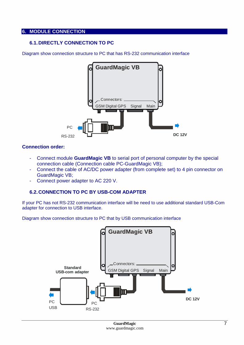
6.1. DIRECTLY CONNECTION TO PC Diagram show connection structure to PC that has RS-232 communication interface
DC 12VRS-232
PC
MainGSM GPSDigital Signal
Connectors:
GuardMagic VB
Connection order:
- Connect module GuardMagic VB to serial port of personal computer by the special connection cable (Connection cable PC-GuardMagic VB);
- Connect the cable of AC/DC power adapter (from complete set) to 4 pin connector on GuardMagic VB;
- Connect power adapter to AC 220 V.
6.2. CONNECTION TO PC BY USB-COM ADAPTER
If your PC has not RS-232 communication interface will be need to use additional standard USB-Com adapter for connection to USB interface. Diagram show connection structure to PC that by USB communication interface
DC 12V
RS-232
PC
MainGSM GPSDigital Signal
Connectors:
GuardMagic VB
StandardUSB-com adapter
USB
PC

GuardMagic www.guardmagic.com
8
7. START THE PROGRAM AND OVERVIEW OF BASIC FORM
7.1. START THE PROGRAM
Copy program “GM VB PT” (VB-programmer.exe) from CD to hard disk of yours PC. Start the program “GM VB PT” (VB-programmer.exe). After start the program on the screen will open the basic form, shown on figure.
7.2. SERVICE LINE Read Only.
Service line located on bottom of the form and is intended to give main information about
connected GuardMagic VB module: • "Unit Type"* – type of module; • "Factory Number"* – factory number of module; • "Firm/Boot" – version of module internal firmware and module
bootloader; * - content of this field will be needed for your monitoring station (monitoring software).
GuardMagic www.guardmagic.com
9
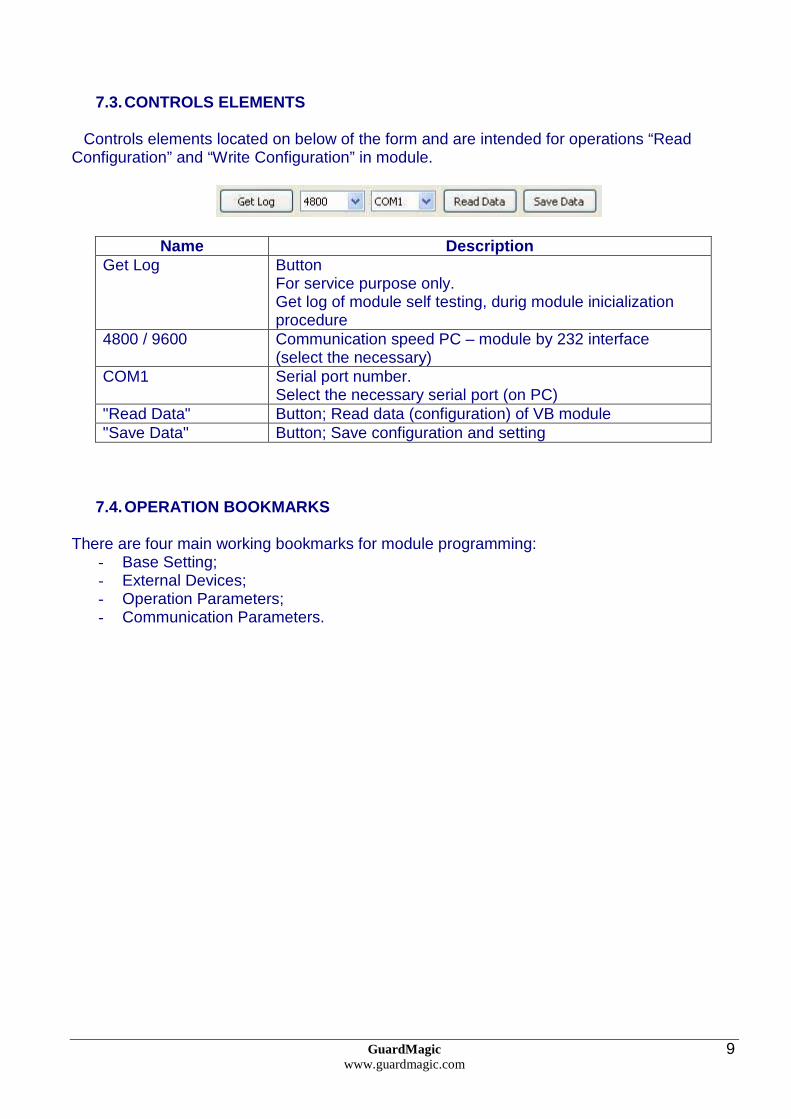
7.3. CONTROLS ELEMENTS
Controls elements located on below of the form and are intended for operations “Read
Configuration” and “Write Configuration” in module.
Name Description Get Log Button
For service purpose only. Get log of module self testing, durig module inicialization procedure
4800 / 9600 Communication speed PC – module by 232 interface (select the necessary)
COM1 Serial port number. Select the necessary serial port (on PC)
"Read Data" Button; Read data (configuration) of VB module "Save Data" Button; Save configuration and setting
7.4. OPERATION BOOKMARKS
There are four main working bookmarks for module programming: - Base Setting; - External Devices; - Operation Parameters; - Communication Parameters.
GuardMagic www.guardmagic.com
10
8. OPERATION BOOKMARKS DESCRIPTION
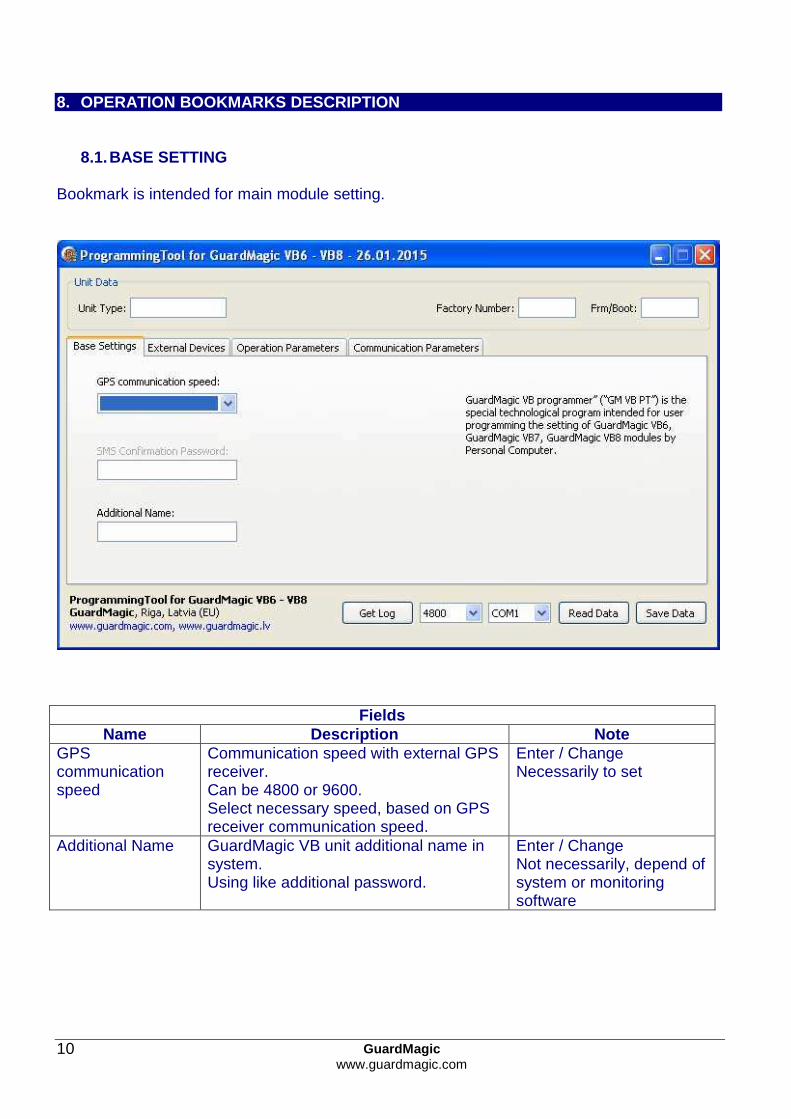
8.1. BASE SETTING Bookmark is intended for main module setting.
Fields Name Description Note
GPS communication speed
Communication speed with external GPS receiver. Can be 4800 or 9600. Select necessary speed, based on GPS receiver communication speed.
Enter / Change Necessarily to set
Additional Name GuardMagic VB unit additional name in system. Using like additional password.
Enter / Change Not necessarily, depend of system or monitoring software

GuardMagic www.guardmagic.com
11
8.2. EXTERNAL DEVICES
Bookmark is intended for configuration external sensors: fuel and temperature (activate deactivate).
Fields Name Description Note
"Group 1 Activation" Fuel sensors group 1 activation "Group 2 Activation" Fuel sensors group 2 activation Main Tank 1..3 Activation of Man Tank 1..3 Cargo Tank 1..11 Activation of Cargo Tank 1..11 Temperature Sensor Activation
Activation function of “Temperature Measurement”.
Sensor Activation Sensor #1..#7
Activation temperature sensors and entering address of temperature sensors on “Temperature Bus”
"Get ID Code" Get ID Code of connected sensor "Main Service Record 2"
Activation of Main Service Record 2
"FST-code Record" Activation of FST-code Record "Maximum RPM Pulses"
Set the value of Maximum RPM Pulses 7 680 or 61 440 RPM
DVS1 .. DVS6 Activation of Density/Viscosity sensor ( record)

GuardMagic www.guardmagic.com
12
8.3. OPERATION PARAMETERS
Bookmark is intended for programming module operation mode and operation parameters.
Fields
Name Description Note "Operation Mode" Select type of unit operation mode:
“Real Time” or “Packet” “Real Time”- Internal Memory Off “Packet” -internal memory On. Store information when module is outside GSM coverage
"Packet Size" The size of Packet transmitting size on “Packet Mode”
Recommend set 4 or 8
“Adaptive Speed” Activate adaptive data fixing by speed change
Recommend activate
"Ignition" Activate the necessary type of “engine On/Off” detection
Standard (Normal); Virtual RPM; Virtual 12V; Virtual 24V
"Active Standby" Activation of Active Standby function “Off” , 15 min; 1 hour; 4 hour “Duration” Duration of Active Standby mode 1 day, 2 day, 7 days
(recommend set 1 or 2 days) "Transport Type" Select one type of transport Vehicle; Special machinery "Data Fixing " Periodicity of data fixing

GuardMagic www.guardmagic.com
13
Fields
Name Description Note "Overspeed buzzer"
Activate sounds overspeed notification
"i-Buttons codes" Field for entering iButton code Driver ID code (iButton Key) Switch “Immobilizer”
Activate/Deactivate immobilizing function
If immobilizing function activated: is possible to start engine only after correct driver identification. Driver i-button codes have to be entered in to module
Switch "Blocking" block/unblock blocking output in manual 8.3.1 IGNITION
Type of Engine On / Off detection:
Name Description Notes Standard (Normal) By connection to Ignition switch (Ignition key)
Standard configuration Strongly recommend
Virtual by RPM By connection to RPM sensor. If is not possible possible to make electrical connection to ignition circuit (Ignition switch). Available connection only to RPM sensor
Virtual 12V By fluctuation of vehicle power voltage If is not possible to make electrical connection to ignition circuit (Ignition switch). For 12 V vehicle
Virtual 24 V By fluctuation of vehicle power voltage If is not possible to make electrical connection to ignition circuit (Ignition switch). For 24 V vehicle
8.3.2 OVERSPEED BUZZER Two step overspeed buzzer. Single beep: oversped of single beep field Constant beep: overspeed of constant beep field Constant beep field have to be higher that single beep field
GuardMagic www.guardmagic.com
14
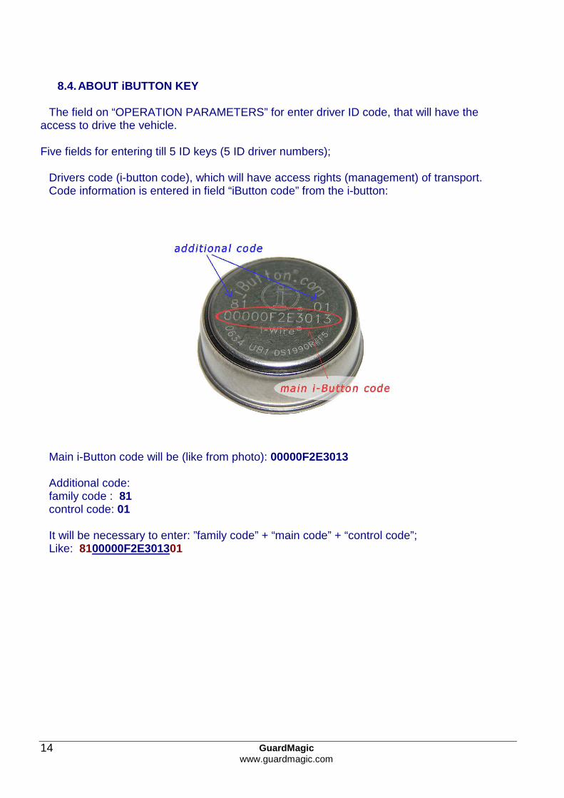
8.4. ABOUT iBUTTON KEY The field on “OPERATION PARAMETERS” for enter driver ID code, that will have the
access to drive the vehicle. Five fields for entering till 5 ID keys (5 ID driver numbers);
Drivers code (i-button code), which will have access rights (management) of transport. Code information is entered in field “iButton code” from the i-button:
Main i-Button code will be (like from photo): 00000F2E3013 Additional code: family code : 81 control code: 01 It will be necessary to enter: ”family code” + “main code” + “control code”; Like: 8100000F2E301301

GuardMagic www.guardmagic.com
15
8.5. COMMUNICATION PARAMETERS
Bookmark is intended for programming module communication parameters.
Fields Name Description Note
APN access point name - APN server of yours GSM provider;
Given by GSM provider; Necessary field
GPRS User Name * user name for access to a server of yours GSM the provider
Given by GSM provider Necessary
GPRS Password* password for access to the server of yours GSM the provider;
Given by GSM provider
Host IP1 IP address of Main monitoring station (server IP address);
Given by monitoring station (monitoring software); Necessary field
Host IP1 port port number of Main monitoring station server.
Given by monitoring station (monitoring software); Necessary field
Host IP2 IP address of Reserve monitoring station (server IP address);
Given by monitoring station (monitoring software)
Host IP2 port port number of Reserve monitoring station server.
Given by monitoring station (monitoring software)
* - often GSM provider has not (and don’t give) Name and Password to access to its GPRS server.
GuardMagic www.guardmagic.com
16
Fields
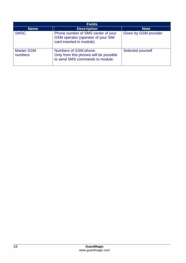
Name Description Note SMSC Phone number of SMS center of your
GSM operator (operator of your SIM card inserted in module)
Given by GSM provider
Master GSM numbers
Numbers of GSM phone. Only from this phones will be possible to send SMS commands to module.
Selected yourself
GuardMagic www.guardmagic.com
17
9. STARTING OPERATION WITH PROGRAM
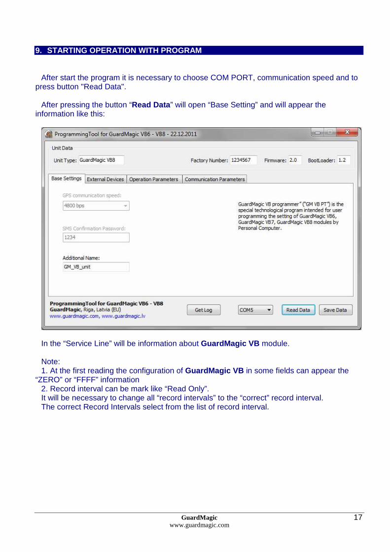
After start the program it is necessary to choose COM PORT, communication speed and to
press button "Read Data". After pressing the button “Read Data ” will open “Base Setting” and will appear the
information like this:
In the “Service Line” will be information about GuardMagic VB module. Note: 1. At the first reading the configuration of GuardMagic VB in some fields can appear the
“ZERO” or “FFFF” information 2. Record interval can be mark like “Read Only”. It will be necessary to change all “record intervals” to the “correct” record interval. The correct Record Intervals select from the list of record interval.
GuardMagic www.guardmagic.com
18
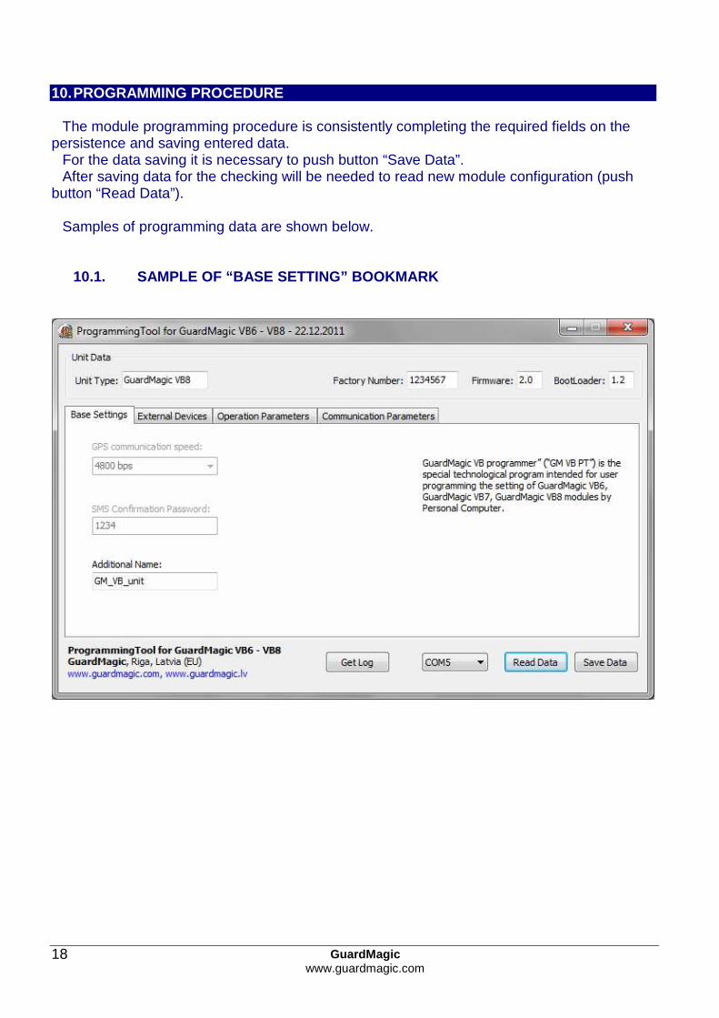
10. PROGRAMMING PROCEDURE
The module programming procedure is consistently completing the required fields on the
persistence and saving entered data. For the data saving it is necessary to push button “Save Data”. After saving data for the checking will be needed to read new module configuration (push
button “Read Data”). Samples of programming data are shown below.
10.1. SAMPLE OF “BASE SETTING” BOOKMARK

GuardMagic www.guardmagic.com
19
10.2. SAMPLE OF “EXTERNAL DEVICE” BOOKMARK
10.3. SAMPLE OF “OPERATION PARAMETERS” BOOKMARK
GuardMagic www.guardmagic.com
20
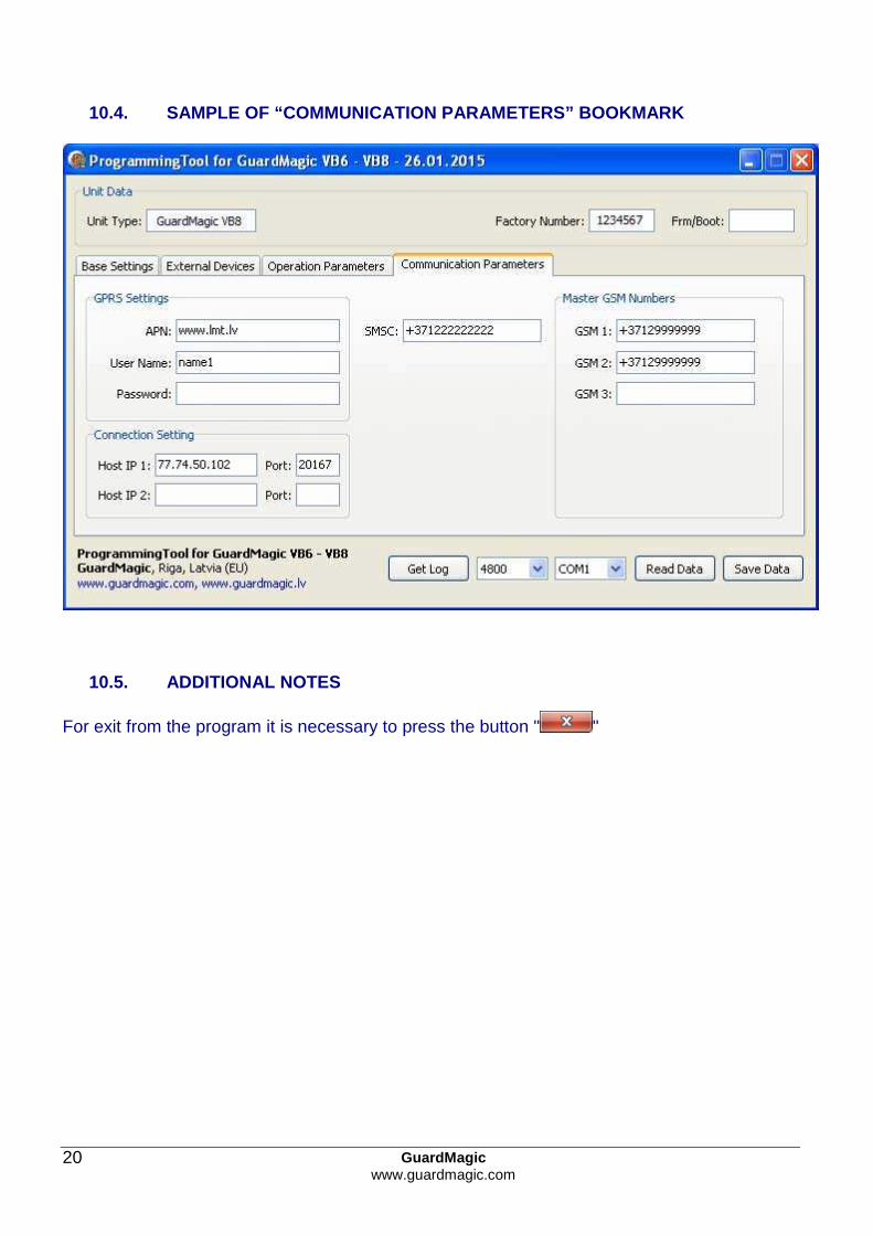
10.4. SAMPLE OF “COMMUNICATION PARAMETERS” BOOKMARK
10.5. ADDITIONAL NOTES
For exit from the program it is necessary to press the button " "
GuardMagic www.guardmagic.com
21
11. WIRING DIAGRAMS OF GuardMagic VB
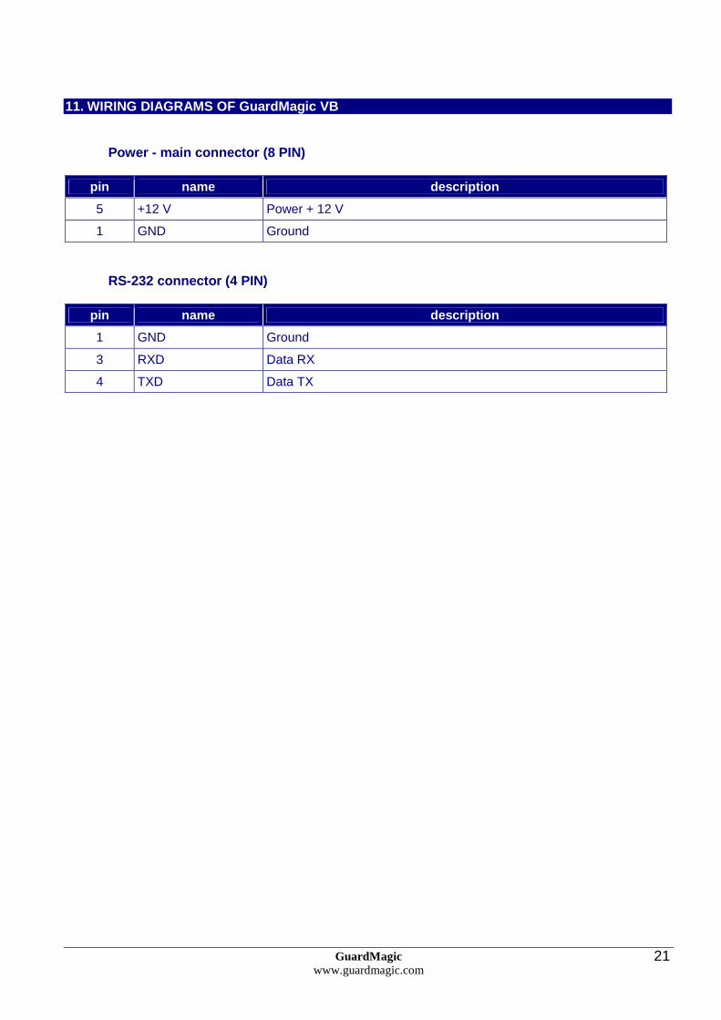
Power - main connector (8 PIN)
pin name description
5 +12 V Power + 12 V
1 GND Ground
RS-232 connector (4 PIN)
pin name description
1 GND Ground
3 RXD Data RX
4 TXD Data TX
GuardMagic www.guardmagic.com
22
12. APPENDIX 1 - Digital thermometer ID number read ing
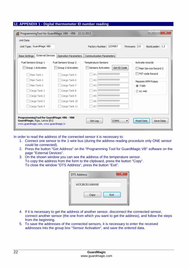
In order to read the address of the connected sensor it is necessary to:
1. Connect one sensor to the 1-wire bus (during the address reading procedure only ONE sensor could be connected).
2. Press the button "Get Address" on the "Programming Tool for GuardMagic VB" software on the page "External Devices".
3. On the shown window you can see the address of the temperature sensor. To copy the address from the form to the clipboard, press the button "Copy". To close the window "DTS Address", press the button "Exit".
4. If it is necessary to get the address of another sensor, disconnect the connected sensor, connect another sensor (the one from which you want to get the address), and follow the steps from the beginning.
5. To save the addresses of the connected sensors, it is necessary to enter the received addresses into the group box "Sensor Activation", and save the entered data.