vast lite volume annotation and segmentation … lite v1_1...volume annotation and segmentation tool...
TRANSCRIPT

VAST Lite
Volume Annotation and Segmentation Tool
User Manual, VAST Lite 1.1 RC1
Daniel R. Berger
May 22nd, 2017

ii

Contents
1 Introduction 1
2 Getting Started 52.1 System Requirements . . . . . . . . . . . . . . . . . . . . . . . . . . . . . . . . . . 52.2 Program Setup . . . . . . . . . . . . . . . . . . . . . . . . . . . . . . . . . . . . . 5
2.2.1 Try It Out! . . . . . . . . . . . . . . . . . . . . . . . . . . . . . . . . . . . . 62.2.2 Preferences . . . . . . . . . . . . . . . . . . . . . . . . . . . . . . . . . . . 6
2.3 Additional Files Included With VAST . . . . . . . . . . . . . . . . . . . . . . . . . . 8
3 Working with VAST 93.1 Image Stack Importing . . . . . . . . . . . . . . . . . . . . . . . . . . . . . . . . . 9
3.1.1 Importing image stacks: Pattern-based names . . . . . . . . . . . . . . . . . 103.1.2 Lossless and lossy compression . . . . . . . . . . . . . . . . . . . . . . . . . 113.1.3 Importing 3D volume files . . . . . . . . . . . . . . . . . . . . . . . . . . . . 123.1.4 Image scale and description . . . . . . . . . . . . . . . . . . . . . . . . . . . 12
3.2 Viewing and Navigating an Image Stack . . . . . . . . . . . . . . . . . . . . . . . . 123.2.1 Remote image stacks . . . . . . . . . . . . . . . . . . . . . . . . . . . . . . 133.2.2 The sidebar . . . . . . . . . . . . . . . . . . . . . . . . . . . . . . . . . . . 133.2.3 The RAM usage indicator . . . . . . . . . . . . . . . . . . . . . . . . . . . . 143.2.4 Getting and setting coordinates . . . . . . . . . . . . . . . . . . . . . . . . . 143.2.5 Layers . . . . . . . . . . . . . . . . . . . . . . . . . . . . . . . . . . . . . . 14
3.3 Painting . . . . . . . . . . . . . . . . . . . . . . . . . . . . . . . . . . . . . . . . . 163.3.1 Multi-scale painting . . . . . . . . . . . . . . . . . . . . . . . . . . . . . . . 173.3.2 Automatic Z-filling . . . . . . . . . . . . . . . . . . . . . . . . . . . . . . . 183.3.3 Using conditional painting . . . . . . . . . . . . . . . . . . . . . . . . . . . 18
3.4 Segments . . . . . . . . . . . . . . . . . . . . . . . . . . . . . . . . . . . . . . . . 193.4.1 Picking segments . . . . . . . . . . . . . . . . . . . . . . . . . . . . . . . . 193.4.2 The segment hierarchy . . . . . . . . . . . . . . . . . . . . . . . . . . . . . 193.4.3 Re-ordering and moving segments in the tree . . . . . . . . . . . . . . . . . 193.4.4 Collapsing and expanding tree branches . . . . . . . . . . . . . . . . . . . . 203.4.5 Using anchor points . . . . . . . . . . . . . . . . . . . . . . . . . . . . . . . 203.4.6 Adding new segments . . . . . . . . . . . . . . . . . . . . . . . . . . . . . . 203.4.7 Helper functions for arranging segments . . . . . . . . . . . . . . . . . . . . 203.4.8 Select recently selected segments . . . . . . . . . . . . . . . . . . . . . . . . 213.4.9 Global operations: Deleting and welding segment subtrees . . . . . . . . . . 213.4.10 Segment tags . . . . . . . . . . . . . . . . . . . . . . . . . . . . . . . . . . 213.4.11 Editing the color of a segment . . . . . . . . . . . . . . . . . . . . . . . . . 213.4.12 Exporting segment metadata . . . . . . . . . . . . . . . . . . . . . . . . . . 223.4.13 Segment information . . . . . . . . . . . . . . . . . . . . . . . . . . . . . . 22
iii

iv CONTENTS
3.4.14 Searching for a segment with a given name or ID . . . . . . . . . . . . . . . 223.4.15 The ’Collect’ tool . . . . . . . . . . . . . . . . . . . . . . . . . . . . . . . . 22
3.5 Saving Segmentations . . . . . . . . . . . . . . . . . . . . . . . . . . . . . . . . . . 233.5.1 Save Segmentation As Special . . . . . . . . . . . . . . . . . . . . . . . . . 23
3.6 Segmentation Merging . . . . . . . . . . . . . . . . . . . . . . . . . . . . . . . . . 233.7 Importing Segmentations From Image Stacks . . . . . . . . . . . . . . . . . . . . . 243.8 Exporting Image Stacks . . . . . . . . . . . . . . . . . . . . . . . . . . . . . . . . . 253.9 The 3D Viewer . . . . . . . . . . . . . . . . . . . . . . . . . . . . . . . . . . . . . 27
4 The VastTools Matlab Toolbox 294.1 Getting started with the VastTools Matlab Toolbox . . . . . . . . . . . . . . . . . . 294.2 Exporting 3D Models . . . . . . . . . . . . . . . . . . . . . . . . . . . . . . . . . . 294.3 Exporting Projection Images . . . . . . . . . . . . . . . . . . . . . . . . . . . . . . 324.4 Measuring . . . . . . . . . . . . . . . . . . . . . . . . . . . . . . . . . . . . . . . . 34
4.4.1 Measure Segment Volumes . . . . . . . . . . . . . . . . . . . . . . . . . . . 344.4.2 Measure Segment Lengths . . . . . . . . . . . . . . . . . . . . . . . . . . . 344.4.3 Measure Segment Surface Area . . . . . . . . . . . . . . . . . . . . . . . . . 354.4.4 Euclidian Distance Measurement Tool . . . . . . . . . . . . . . . . . . . . . 35
4.5 Simple Navigator Images . . . . . . . . . . . . . . . . . . . . . . . . . . . . . . . . 354.6 Target Lists . . . . . . . . . . . . . . . . . . . . . . . . . . . . . . . . . . . . . . . 35
A FAQ and Trouble Shooting 37A.1 Frequently Asked Questions . . . . . . . . . . . . . . . . . . . . . . . . . . . . . . . 37A.2 Typical Use Cases . . . . . . . . . . . . . . . . . . . . . . . . . . . . . . . . . . . . 39A.3 Some Performance Tips . . . . . . . . . . . . . . . . . . . . . . . . . . . . . . . . . 40A.4 Setting up VAST with a Wacom screen . . . . . . . . . . . . . . . . . . . . . . . . 40A.5 Keyboard Shortcuts in VAST . . . . . . . . . . . . . . . . . . . . . . . . . . . . . . 41A.6 Terms of Usage and Privacy Statement . . . . . . . . . . . . . . . . . . . . . . . . 42
B Technical Information 43B.1 Size limitations . . . . . . . . . . . . . . . . . . . . . . . . . . . . . . . . . . . . . 43B.2 Supported file formats for importing / exporting . . . . . . . . . . . . . . . . . . . . 43B.3 API Function Reference . . . . . . . . . . . . . . . . . . . . . . . . . . . . . . . . . 44

Chapter 1
Introduction
VAST is a utility program for manual annotation and segmentation of large volumetric image (voxel)data sets. It enables users to work with data sets in the Terabyte or even Petabyte range at interactivespeeds, to explore them visually and to label structures of interest by voxel painting.
Voxel painting has a number of advantages over other manual segmentation approaches likebread crumbing (placing a number of labeled points inside each object) and skeletonization (placinglabeled points and connecting them with edges to form a ’skeleton’). It reveals the true shape ofobjects and makes visualizations of the data more comprehensive. It also allows measurement ofvolume and surface shape properties of the labeled objects. When working on a dense segmentation,the fact that voxel painting labels areas rather than single points or lines in the cross-sections ofobjects makes it a lot easier to spot objects that have not been labeled yet (visual pop-out). Italso allows for some additional functionality, for example reliably determining neighbor regions, usingvoxel overlap of several segmentations for merging regions or determining synaptic connectivity, andconditional painting. Such functions are also difficult to implement when using outline labeling(drawing vectorized lines around process cross-sections in 2D slices). In addition, outline labelingcan introduce problems in identifying corresponding outlines in different slices and can cause regionoverlap. Also, many machine learning algorithms for automatic segmentation rely on voxelizedlabelings for training, and the output of many such algorithms are labeled voxelized regions. VASTcan be used to generate volumetric training data sets in their native format, and can to some extentalso be used for importing, proof-reading and correcting results of segmentation algorithms.
The disadvantages of voxel painting which are mentioned most often are that it is slower thanfor example skeletonization or bread crumbing, and that it needs more storage space than alternativemethods, especially when working with very large data sets. VAST tries to alleviate both disadvan-tages. For voxel painting, the time needed to label an object is largely determined by the number ofoutlines that have to be drawn. VAST can do automatic convex Z-filling to reduce the number ofoutlines by a factor of up to 8 if accurate boundary tracing is not needed. Painting is also optimizedto be highly responsive, and the user interface provides quick access to functions which are usedoften (navigating through the image stack, changing the tooltip size, color picking, and switchingbetween paint and delete mode). To reduce the amount of required memory and to enable interactivepainting speed with any tooltip size, VAST implements multi-scale painting.
Considering that alternative labeling methods are likely to be more error-prone and will probablyrequire more time until an acceptably low error rate is reached, voxel painting might be the overallfaster alternative for fully manual labeling. If an object skeleton is needed (for example to computelength of a dendrite or number of spines etc.), it can be computed from the voxelized segmentation,whereas the inverse operation (computing accurate volumes from skeletons) is much harder. In apreliminary test we found that using VAST, a very experienced user can produce a dense segmentationof well-stained and well-aligned cortex neuropil data (6x6x30 nm voxel size) at a speed of about 4
1

2 CHAPTER 1. INTRODUCTION
cubic microns per hour. If cross-sections are labeled with a color dot in the middle rather thanaccurately outlining and filling the cross-sections, the labeling speed can be increased by a factor of3 at the expense of accuracy (12 cubic microns per hour).
VAST is also very portable and light-weight. It consists of a single Windows executable file whichis independent of third-party libraries. It does not require to be installed and can be easily copiedand for example run from a memory stick.
Many tools for labeling voxel data exist, but such tools usually have drawbacks when it comes topainting in large data sets. Most tools do not support voxel painting but instead do bread crumbing,skeletonizing or storing object outlines as vector graphics (for example splines). Also most of themrequire the data to be loaded in RAM completely. This is not possible for the data sets in the Terabyte(and soon Petabyte) range which are currently produced by serial-section electron microscopy ofbiological samples. Many of these tools are also developed as cross-platform applications, so thatthey can be run on Windows, Mac and Linux systems. This usually means that a non-native GUIsystem has to be used (e.g. Qt) which makes the program a lot more bulky and more difficult toinstall and maintain. VAST is a Windows-only program and uses native Windows GUI and graphicsfunctions.
VAST is currently being used in several scientific projects to label cells in electron-microscopicand light microscopic image stacks. It was also used for the recently published studies [3], [4], [5]and [6].
The key concepts of VAST are:
• Image stacks are imported into VASTs .vsv file format, where they are stored as dices. This,together with pre-computation of mip maps, allows for fast panning and zooming through thedata when it is opened in VAST.
• .vsv files support lossless and lossy compression to reduce the resulting file size
• Image data and segmentations are stored in single files, which makes it easy to copy them fromone place to another
• Support for loading EM stacks from a web server over HTTP (openconnecto.me, neurodata.ioand butterfly formats)
• Dynamic multi-threaded cacheing in RAM with pre-loading for low-latency display update
• Layering: Several image and segmentation stacks can be opened and displayed together witha number of blending and tinting options
• Multi-scale painting (in VAST, painting always happens at the currently displayed resolution(mip level))
• Automatic convex Z-filling during painting to speed up coarse labeling
• Automatic 2D-filling of closed contours
• Label color patterns create a larger number of distinguishable label colors
• Label hierarchies allow for fast and reversible grouping of labeled segments in a tree structure
• Segments have anchor points to quickly find them in the volume
• Exporting of segmentations, EM stacks and mixed image stacks (’screenshots’) in multipleformats
• Importing of segmentations from image stacks

3
• File-modification free editing. Image files are not changed (except if you explicitly updateinformation in them). Segmentation files are only changed it you save the segmentation backto the same file.
• TCP/IP-based API through which external programs can directly communicate with VAST, andsupporting Matlab script ’VastTools’ which provides supplementary functions like measuringlabeled segments and exporting of 3D surface models.
Current limitations:
• Currently only 16-bit segmentations are supported
• There is no ’Undo’ function
• Exporting of 3D models of segmented objects is currently only supported externally (using theVastTools Matlab script)
• No 3D model display
• No multi-user support
• Not an open-source project, but the VAST Lite executable can be copied and used freely (seesection A.6 for details)
Please note that VAST is still under development, and is subject to change as new featuresare added and bugs are fixed. For bug reports or helpful suggestions, please contact me at:[email protected].

4 CHAPTER 1. INTRODUCTION

Chapter 2
Getting Started
2.1 System Requirements
VAST currently runs on 32- and 64-bit Windows computers that support DirectX 11. These areWindows Vista, 7, 8 and 10, with DirectX 11 or later available. Windows XP and older versions willnot work. 64 bit versions of these operating systems are recommended, because 32 bit programsare limited in the amount of RAM they can handle (4 GB max. theoretically, less realistically). Thecomputer also has to have a DirectX 11 compatible graphics card. In most modern computers eventhe on-board graphics chips support DirectX 11.
Recommended system configuration:
• Windows PC with 64 bit Windows 7 or later
• 16 GB of RAM (the more the better)
• DirectX 11 compatible graphics card
• 2 TB of disk space (depends on the size of the data you work with)
• Wacom Cintiq 13HD or other pen touch screen with configurable two-button pen
Minimal system configuration:
• Windows PC with 32 bit Windows 7
• 2 GB of RAM (at least 4 GB recommended)
• DirectX 11 compatible on-board graphics card
• Standard screen and mouse
2.2 Program Setup
To use VAST, simply copy the executable program into a folder where you have read/write access,and set up links on your desktop, start menu and/or taskbar if desired. It is important that VASThas read and write access to the folder where the executable is because it will write a configurationfile (vast_preferences.dat) into the same folder to store your settings.
Start the executable.
5

6 CHAPTER 2. GETTING STARTED
2.2.1 Try It Out!
The quickest way to try out VAST is to use an online data set. Several online data sets are includedin the .ZIP package of supplementary files as .VSVR files. You can save this package from theexecutable by clicking ’Yes’ in the ’First Start’ pop-up window when you start VAST for the firsttime, or by choosing ’Save Documentation .ZIP To Disk...’ from the ’Info’ menu.
Unzip the package (or drag&drop the contents to a folder outside the .ZIP using WindowsExplorer for example). Then, in VAST, go to ’Open EM...’ and select one of the .VSVR files in theVAST_package/Online Datasets/ folder, for example ’neurodata_kasthuri11.vsvr’. This willload images of a big EM stack from the Johns Hopkins neurodata.io server. Your computer hasto have internet access for this to work.1
Click and drag the EM slice to pan. Use the mouse wheel to zoom. Use UP/DOWN arrow keysor A/Z to scroll through the stack.
Click on the little pencil icon in the toolbar to switch to ’Paint’ mode. Choose ’Yes’ in the popupwindow. Click and drag over the image to paint. You can select different paint colors in the ’SegmentColors’ tool window. To erase, hold down the ’Delete’ key while painting (or click and hold the rightand left mouse buttons together). Select ’Keyboard Shortcuts’ from the ’Window’ menu for a list ofavailable keyboard functions.
2.2.2 Preferences
In the main menu of VAST, go to ’File / Preferences ...’ to open the Preferences dialogwindow. Here you can set the parameters for data cacheing and display. VAST will set up thepreferences for you when you run it for the first time on a computer (whenever it cannot findthe preferences file). You can edit these preferences if you want to. You should at least checkonce whether the folder in which VAST puts its temporary disk cache is on a hard drive with lotsof free space. Depending on what you do, temporary disk cache files can get similarly large asthe segmentation files you are working with, in particular if you use global segmentation editingfunctions like merging, segment deleting, or segment welding. Each VAST instance will write acache file (vastsegcache*.vss) to this folder and delete it when VAST is closed. In case VASTcrashed (which should not happen) or power was lost while VAST was running, a cache file may beleft there which takes up disk space, so you may want to check for and delete old cache files once ina while if VAST was terminated anormally.
Memory and Cacheing
On the left side of the Preferences dialog you can set how much cache memory VAST will usemaximally for voxel images and for segmentations. VAST chooses initial values which are reasonablefor your system. The rule of thumb is: If you can afford it, leave 1-2 GB for the system, and splitthe rest 1/3 each for image cache, segmentation cache, and general usage of VAST (don’t assign).On a system with 8 GB RAM, this means to give 2000 MB to the image RAM cache and 2000 MBto the segmentation RAM cache. If you are only viewing images and not using segmentations, youcan increase the size of the image cache and reduce the size of the segmentation cache accordingly.If you plan to use other programs at the same time or run two instances of VAST, please reducethese values as needed. VAST will not immediately use all of the allotted memory, but it will stopreserving new memory for cache blocks and re-use old blocks when it reaches the limit.
In general, do not allow VAST to allocate more memory than the system has. This can result insevere performance issues. There is a memory usage indicator in the upper right corner of the VASTwindow which shows you how much memory is currently used. The blue frame indicates the maximum
1Remote EM images are loaded from a server using a cutout service over HTTP. The VSVR file is just a text filewhich defines the web address of the dataset to load and its dimensions.

2.2. PROGRAM SETUP 7
amount of RAM which VAST uses for image and segmentation cacheing. If the memory indicatorbecomes red and your system slows down, try to REDUCE the cache limits to allow Windows andVAST to use more RAM for other data.
Some of the segmentation cache is used for holding the currently displayed part of the seg-mentation in memory. When you exit the preferences dialog, VAST will tell you how much of thesegmentation cache it needs for the current display settings and whether the cache size is sufficient.
’Disk Cache Directory’: Here you can specify the folder where VAST stores its temporarydisk cache. Click the ’[ ... ]’ button to browse. Set this to a folder where you have lots of freespace (more than the size of the largest segmentation file you will be working with, since for certainfunctions VAST has to duplicate the segmentation data).
Painting
The segmentation bit depth is currently fixed at 16 bits. This allows for a maximum of 65535 labels;however, since each segment is represented in the tree view of the ’Segment Colors’ window in VAST,memory limitations in the Windows system might prevent VAST from using that many labels.2
’Tablet Mode (Pen Paints, Finger Moves)’: On some pen-enabled tablet computers VASTcan distinguish finger and pen input. If this mode is enabled, the pen should paint and the fingershould move the view when in Paint Mode. This may not work on some newer systems.
’Generate New Colors From:’: Allows you to select which color space to use for assigningrandom colors to new segments. Segment colors can of course also be changed manually (seesection 3.4.11).
Display Properties
’Maximum Window Width’ specifies the width (or height, whichever is greater) of the largest windowyou will be using, in pixels. This value is used to determine how many textured tiles are needed tofill the entire window at all zoom levels. Setting this value smaller reduces memory consumption andincreases cacheing speed, but if the value is too small, the image texture might not reach all the wayto the sides of the window at all zoom levels.
’Target Resolution Smaller Than’ lets you specify the effective resolution of the displayedtextures on the screen in screen pixels per texture pixel. This affects at what zoom levels whichmipmaps are used. ’2’ is a good general setting; ’1’ makes it more detailed but slower (and morememory-consuming), and ’4’ makes it faster but blurry.
’Texture size m (texture is m^2):’ defines how large the texture tiles will be which areused for displaying image and segmentation textures. Depending on the graphics card some texturesizes might be faster than others. I recommend to leave this setting at 128.
’Texture Smoothing’: You can set here whether you want to use texture interpolation. Thisreduces aliasing effects but can result in a slightly blurred appearance of the textures. The mostnatural setting of this is, in my opinion, ’All except Mip 0’, which will show pixels with sharpboundaries only if you zoom in more than the native resolution of the image data.
’Link Tool Windows’: When enabled, VAST’s floating tool windows will automatically move totheir default locations with respect of the main window when the main window is moved or rescaled.
The remaining options are self-explanatory. Opacity values have to be set between 0 (fullytransparent) and 255 (fully opaque).
Other
’Enable API Remote Connections at Startup’: This can be useful to enable if you often usethe VAST API to link to external programs. The API remote connection functionality can also be
2It runs fine with more than 36000 labels in one of our data sets.

8 CHAPTER 2. GETTING STARTED
enabled and disabled in the ’Remote Control API Server’ dialog under ’Window’ in the VASTmain menu.
Press OK after you’re done configuring the preferences.
2.3 Additional Files Included With VAST
Under ’Info / Save Documentation .ZIP To Disk ...’ in the main menu you can save outadditional files which are packaged into the VAST executable, as a ZIP file. Select a target locationand save, then unzip the ZIP file.
Currently this includes a set of .vsvr files to access some large EM data sets remotely (seesection 3.2.1), some Matlab scripts which can be useful for analyzing VAST data in Matlab, includingthe VastTools toolbox which can communicate directly with VAST through the API and providesadditional functionality (see chapter 4), and this documentation as a PDF file.
Chapter 3
Working with VAST
VAST uses its own file format .VSV1 to store image data. It can open .VSV files immediately andnavigate in them quickly. If your data is a stack of for example .PNG images, you will have to importit into VAST before you can use it. During importing the data will be saved into a VAST-specific.VSV data file, which allows quick access to arbitrary parts of the data. After opening a .VSV imagefile, you can create a segmentation by painting on top of the images, or you can open an associatedsegmentation file (.VSS)2 and view image and segmentation together. VSS files tend to get bigquickly, but can be packed efficiently, for example in a ZIP file. You can view segmentations, modifyand save them. You can export segmentations as image stacks for using them in other analysisprograms or to render the segmented objects in a 3D animation program like 3D Studio MAX. Youcan also import segmentation image stacks that were generated externally.
3.1 Image Stack Importing
Typically volumetric image data is stored as a series of 2D images, or as a serial 3D block of data,which is not suitable for fast interactive viewing. When you import such a data set into VAST, it putsthe images into a single file containing a diced data structure, and computes and includes mipmapsfor the images.3 Using diced data does not only speed up loading of parts of images, but will in thefuture also enable fast loading of volumetric sub-regions or 2D sections at other orientations throughthe image data.
VAST does currently not include image alignment and stitching functions. If you are starting withan unaligned stack of images, you will first have to align the images with a different program (Fiji orPhotoshop, for example) and then save a stack of aligned images which all have the same dimensionsand are named and numbered in a consistent way (for example img000.png, img001.png, ...).Put all images into the same folder.
VAST can import single-tile image stacks, multi-tile image stacks, and 3D volume files. In asingle-tile image stack, each slice of the stack consists of a single image file. In a multi-tile imagestack, each slice is composed of several tiles in a XY grid, and each tile is stored in a separate imagefile. A 3D volume file stores all slice images in a single file. Currently the only 3D volume file formatthat VAST supports is NIfTI (.nii). VAST will convert image data to either 8-bit graylevel or 24-bitRGB when importing.
1.VSVOL can be used instead, and may be preferable, because Microsoft thinks .VSV is a ’Microsoft Visio’ file.2You can use .VSSEG instead of .VSS as an alternative file name extension for VAST segmentation files.3A mipmap is a downsampled version of an image. VAST uses power-of-two (2D, XY) mipmaps. For example, for
an original image of 1024x1024 pixels, it will compute mipmaps of 512x512 and 256x256 pixels. It does this for everyslice image in a stack.
9

10 CHAPTER 3. WORKING WITH VAST
Figure 3.1: First dialog for importing EM image stacks: Specification of pattern-based names
For importing and dicing, VAST will use the RAM cache which is normally used for cacheing EMimage data during viewing and painting. Having lots of cache memory available will make importingsomewhat faster, because images have to be re-loaded less often. You can set the size of the EMimage cache in the Preferences (see section 2.2.2).
3.1.1 Importing image stacks: Pattern-based names
In the main menu of VAST, go to ’File / Import EM Stack from Images ...’. VAST will showa file browser dialog in which you can select one or several image files. For importing 3D NIfTI files,please select only one file. If you import a single-tile stack and do not want to use pattern-basednames, select all slice images in the correct order, because images will be stacked in the same orderin which they appear in the system’s list of selected files. The order is usually correct if you selectthe last image first, then shift-click (hold the SHIFT key down and click left with the mouse) thefirst image to select the whole range. You can also try ’Select All’ by pressing CTRL-A if the folderonly contains the image files you want to import. If you are worried about the order of the imagesand want more precise control, you can use pattern-based names. If you make use of pattern-basednames to import single- or multi-tile image stacks, it is sufficient to select one file, but even betterto select the first and the last file in your set of images. Then click ’Open’.
After selecting one or more image files (not .nii), VAST will display the dialog shown in Figure3.1. To import without pattern-based names, select ’Make Single-Tile Stack Using File Names andOrder as Selected’ and press OK.
If you select the second option, ’Use Pattern-Based Names’, the parameters in the lower partof the dialog window will be enabled. With pattern-based names, you specify a template string forthe file names which contains placeholders for numbers, and ranges for these numbers. With thisyou can also import image stacks in which each slice is stored in several image files (multi-tile imagestacks). This is useful for data sets in which a single slice is so large that it can not be stored in asingle image file, but is stored in a set of tiles which form a regular grid. Please note that these tilesshould not be unstitched image tiles as they come off a microscope, but they have to fit seamlessly.If you have a set of raw microscopic images which are not yet stitched and aligned, please use anexternal program to generate a stitched and aligned image stack first, and store each slice as a single

3.1. IMAGE STACK IMPORTING 11
Figure 3.2: Second dialog for importing EM image stacks: Image compression options
image or a set of image tiles. You can then import those images into VAST.VAST will use the file(s) you selected in the previous dialog to determine the source directory
where the image files are and to generate a basic template for the file name. It assumes that allimages of the stack are in the same folder (the one you picked an image from), and are namedconsistently with numbers for slices, rows and columns. It also assumes that the set of images iscomplete, which means that there’s an image for every slice/row/column combination in the rangeyou give. In this dialog, you specify these ranges as well as a schema to derive the filename for agiven slice/row/column coordinate.
Let’s say, for example, you have a data set called ’bigstack’, which has 1000 slices, numberedfrom 0 to 999, and each slice has 10x8 tiles, numbered from 1 to 10 and 1 to 8. Assume the imagein the upper left corner of the first slice is called ’bigstack_s0000_x01_y01.png’, the image tileright of it is called ’bigstack_s0000_x02_y01.png’, and so on. The last image in the lower rightcorner of the last slice would be called ’bigstack_s0999_x10_y8.png’.
First, make sure that the file name in the edit box at the top contains the correct C++ formatstring (as it is used by printf()). In general, numbers which specify the slice, column and rowcoordinates have to be replaced by codes like ’%d’ (integer number) or ’%04d’ (integer number withzero-padding to 4 digits). VAST will then fill in those numbers for each image. For more informationabout format strings, please refer to a C++ manual or ask the internet.
In the combo box below, select which coordinates are used in the file names, and in which orderthey appear. The edit boxes below let you specify the range of (integer) numbers for the threecoordinates. After you entered all parameters, press OK.
3.1.2 Lossless and lossy compression
Next, VAST will show a dialog where you can specify the color mode and image compression options(Figure 3.2).
Under ’Color Mode’, please select if you want to import the images as 8-bit graylevel or 24-bitcolor images, and for graylevel which source color channel to use. When importing from graylevelimages, please select the first option (’from RED channel’).
Under ’Compression’ you can specify compression options. Under ’Type’ you can select thecompression method - Uncompressed, Variable Bitdepth Compression, zlib Compression, and SpectralCompression. The three different compression algorithms are by themselves lossless, but mightproduce slightly smaller or larger file size depending on your data. Variable Bitdepth Compressionshould be fastest when reading from the compressed files.
’Quantization’ specifies whether the compression should be lossy or lossless. Lossyness is achievedby quantizing, meaning throwing away bits. For example, if you set Quantization to -2 bits, graylevelimages will have only 6 bits resolution (64 different gray levels) rather than 8 bits (256 different gray

12 CHAPTER 3. WORKING WITH VAST
levels). Throwing bits away reduces both file size and image quality.’Voxel Order’ defines in which order the pixels in the images will be stored. This can have an
effect on compressed file size. ’2D Swizzle’ stores pixels in 2D Z-order. I usually get best resultsusing ’2D Swizzle’, but ’3D Swizzle’ might be superior for very well aligned data (e.g. FIB-SEM).
Next VAST will ask you to specify a target location and file name for the resulting .vsv imagevolume file. Use ’.vsv’ as extension for the file name. Choose a location where you have enoughstorage space for the file. The file will not only contain the original image data, but also the mipmaps. For example, if you import 1024 images of 1024x1024 pixels each and store uncompressed,the .vsv file will be approximately 1024 ·1024 ·1024+512 ·512 ·1024+256 ·256 ·1024 = 1409286144Bytes (≈ 1.3 Gigabytes) large. Lossless compression will reduce the file size, and lossy compressioneven more, but by how much depends strongly on your data and the compression method used.
Then, the images will be read, diced, and put into the target file. After that, VAST will computethe mipmaps and put those in the target file too. Depending on the size of the data, this processcan take several hours. For example, a big data set of 350 GB takes about 5 hours to import on arecent desktop machine. The limiting factor is the speed of hard drive access.
You can cancel the importing, but the target file will then be incomplete / corrupted and cannot be used with VAST.
3.1.3 Importing 3D volume files
Importing a 3D volume file is easier than importing an image stack. The only format currentlysupported by VAST is Nifti. VAST will ask you to specify the name of the source (.nii) file andthe name of the target .vsv file. Currently VAST requires the whole Nifti file to be loaded at onceinto RAM, so this only works for smaller volumes. Also, the data in the Nifti file currently has to be8 bit per pixel.
3.1.4 Image scale and description
After importing, VAST will show a dialog where you can set the voxel size in nanometers of yourdata in the file.4 Press ’Save to file’ in the dialog to save the information you entered to the VSV file.The voxel size entered here is used for the scale bar which you can enable in the main menu under’Info / View Scale Bar’, and for scaling models and measurements in VastTools. You can accessand change these numbers for the selected image layer under ’Info / Volume properties ...’in the main menu. This dialog also displays how large your image stack is in voxels.
Under ’Info / EM File Information ...’ in the main menu you can enter and view textwhich will be stored in your VSV file as well. This can contain a description of the data, copyrightinformation, or other.
3.2 Viewing and Navigating an Image Stack
After you imported a stack of images, you can view them interactively. After you closed the program,you can re-open a previously diced data set by using ’File / Open EM Stack ...’ from the mainmenu. VSV files you open will be added to a list under ’File / Open Recent EM Stack’, fromwhere you can quickly access them again. The list contains the 16 most recent VSV files.
You can also open VSV (and VSS) files by drag-and-drop from a file browser (Windows Explorer)onto the VAST window.
VAST currently has a ’Move mode’, a ’Paint mode’, a ’Collect Mode’ and an ’Eyedropper Mode’,which you can set by clicking the tool buttons in the toolbar. The cross of arrows icon selects ’Move
4You can access the same dialog at any time under ’Info / Volume properties ...’ in the main menu.

3.2. VIEWING AND NAVIGATING AN IMAGE STACK 13
mode’ and the little pencil selects ’Paint mode’. In this section we will explain how to use the ’Movemode’. For an explanation of the other modes please refer to section 3.3.
The easiest way to navigate in the image stack is by using the mouse in ’Move mode’. Youcan pan (move the image sideways) by left clicking and dragging it. You can use the mouse wheelto zoom in and out. Alternatively, you can zoom using the N and M buttons, or the sidebar (seebelow). Use the UP and DOWN arrow keys or A and Z to scroll through the slices of the stack, orthe sidebar to scroll more quickly.
3.2.1 Remote image stacks
In addition to using an image stack in VAST which has been imported into a local .VSV file, youcan also open and access image stacks which are hosted online. VAST supports the ’Open Connec-tome Project Cutout Service’ from http://www.openconnecto.me, the newer neurodata.io dataservers and Harvard’s Butterfly cutout service.5 To access a remote image stack you need a .VSVR
file which specifies the parameters of the data set. .VSVR files are text files in a JSON-like format;here is the content of the openconnectome_kasthuri11.vsvr file:
{
"Comment": "Source: http://openconnecto.me/ocp/ca/kasthuri11/info/",
"ServerType": "openconnectome",
"ServerName": "openconnecto.me",
"ServerFolder": "/ocp/ca/kasthuri11",
"SourceDataSizeX": 21504,
"SourceDataSizeY": 26624,
"SourceDataSizeZ": 1850,
"TargetDataSizeX": 10747,
"TargetDataSizeY": 12895,
"TargetDataSizeZ": 1850,
"OffsetX": 0,
"OffsetY": 0,
"OffsetZ": 0,
"OffsetMip": 1,
"TargetVoxelSizeXnm": 6,
"TargetVoxelSizeYnm": 6,
"TargetVoxelSizeZnm": 30,
"TargetLayerName": "Kasthuri11@OpenConnectome"
}
VAST comes with several pre-defined .vsvr files which you can use to open and view someexample data sets.
3.2.2 The sidebar
VAST provides a sidebar for zooming and moving through the stack. The sidebar is a region closeto the left and the right edge of the main window. When you move the mouse cursor to the left orright edge of the window you will see it appear as a transparent white overlay strip.6 Clicking intothe sidebar and dragging the mouse up or down will scroll through the slices of the stack (left mousebutton) or zoom (right mouse button). If you move the mouse cursor too far away from the sideof the window, the view will ’jump back’ to the previous view. If you move the mouse cursor veryclose to the top or bottom of the window while scrolling (not zooming), VAST will start to scrollcontinuously, with a speed depending on mouse cursor position. You can use this function to quicklyscroll through a very large image stack.
5See for example https://arxiv.org/abs/1306.3543. Essentially VAST requests zipped [128x128x16]pixel blocks of the data set from the data server with URLs which specify the requested region, like:http://openconnecto.me/ocp/ca/kasthuri11/zip/6/1,129/1,129/1,17/. The received file is then unzipped to extractthe image data.
6You can set the opacity of the sidebar in the Preferences, under ’Side Bar Opacity’

14 CHAPTER 3. WORKING WITH VAST
3.2.3 The RAM usage indicator
At the right side of the toolbar you can see a little field named ’RAM:’ which shows the current RAMusage in your computer. The blue frame indicates how much RAM VAST will use maximally forsegmentation- and image cache combined. Make sure that this frame is not dedicating more than2/3 of your total RAM (you can adjust these settings in the Preferences, see section 2.2.2). Thesolid blue block shows how much RAM VAST has currently allocated for segmentation and imagecache. The light blue area shows how much memory is allocated by VAST for other purposes. Thegreen area shows how much RAM the Windows system and other programs are using. The colorswill change to yellow if the total memory usage goes above 90%, and red if they go above 96%.Running out of available RAM can slow down your system significantly. However, in some casesWindows uses large amounts of the available RAM for disk caching and can free those instantly ifmore RAM is needed by programs without affecting the system performance.
3.2.4 Getting and setting coordinates
VAST uses a coordinate system with a zero point in the upper left corner of the first slice, with positiveX to the right and positive Y down in the slice, and Z marking the slice number. Coordinates aregiven in pixels at full resolution (the coordinates are independent of the mip map displayed). Thecoordinates displayed in the upper left corner of the main window show the current location ofthe center of the main window. You can switch the displayed coordinates on and off by using’Info / View Coordinates’ from the main menu. Zooming in or out will not move the centerpoint of the window and therefore also not change its coordinates. Getting or setting coordinateswill also use the coordinates of the center of the screen, as do the ’anchor points’ of segments (seesection 3.3). While you drag the slice with the mouse VAST displays a transparent cross whichindicates the location of the center.7
Once you load an image stack, a tool window labeled ’Coordinates’ will appear in the up-per right corner of the main window. If the tool window is not displayed you can open it using’Window / Coordinates’ from the main menu. It shows you the current center coordinates andallows you to read and set these values. The edit field in the tool window is updated as you navigatethrough the stack. To save the current location, simply copy the coordinates from that text field(mark with the mouse and press CTRL-C), then paste it into the text editor of your choice. You canalso set the coordinates by entering or pasting numbers here and pressing Enter. VAST will thenjump to the new coordinates. The exact format of the string does not matter; VAST simply looksfor the first three numbers in the string. VAST does not mind whether there are commas or bracketsor other non-numerical characters.
This function is quite useful if you want to store coordinates of interesting points in an externaltext file or spread sheet. Please keep in mind that the coordinate denotes the center of the currentview. The center is indicated by transparent crosshairs when you pan the view. You can also centerany point by right-clicking that point with the mouse in ’Move’ mode and selecting ’Center’ fromthe context menu.
The dropdown-listbox in the Coordinates tool window lists the up to 64 most recent locationsyou visited. A new entry is added every time you pan the view (but currently not if you scroll throughZ). You can go back to previous locations by selecting the coordinates from this list.
3.2.5 Layers
VAST can open several image and segmentation stacks at the same time, provided that they havethe same stack size. Each stack is listed as a ’Layer’ in the ’Layers’ tool window. The order in thelist defines the order of the layers. Layers BELOW in the list are ’in front’. The segmentation layers
7You can set the opacity of the center cross in the Preferences, under ’Center Cross Opacity’

3.2. VIEWING AND NAVIGATING AN IMAGE STACK 15
are always rendered on top of all image stack layers. You can change the order of the layers bydrag-and-drop in the list. If you can not see all layers in the list, increase the size of the tool windowby dragging a corner.
One image layer, and, if available, one segmentation layer is the selected layer of its kind, and itsname is displayed in bold text in the ’Layers’ tool window. One of these, the one that was clickedlast, is also highlighted, and is the layer for which the ’Layer Properties’ are shown in the ’Layers’tool window, below the list of layers:
• ’Solo’: If this function is enabled, only the currently selected layer will be displayed.
• ’Editable’: Uncheck this for segmentation layers you do not want to accidentally paint into.Disabled for image layers
• ’Visible’ (image stacks only): Transparency value for this layer. Switch off to hide layer.
• ’Bright’ (image stacks only): Image Brightness; switch on to enable brightness control withthe slider
• ’Contrast’ (image stacks only): Image Contrast; switch on to enable contrast control withthe slider
• ’Alpha’ (segmentation stacks only): Opacity value for this layer. Switch off to hide layer.Duplicated in toolbar.
• ’SelAlpha’ (segmentation stacks only): Opacity value for selected segments. Duplicated intoolbar.
• ’Pattern’ (segmentation stacks only): Contrast of segment patterns. Duplicated in toolbar.
VAST can blend image layers with different transparency modes. Click on the button ’Menu’ toaccess more layer options. Under ’Blend Mode’, you can select either ’Blend’ for alpha-blending or’Additive’ for additive blending. The different settings for the transparency computation are:
• ’Flat’: All pixels in the image share the same transparency [Default]
• ’Dark Transparent’: The darker a pixel ((R+G+B)/3), the more transparent it is
• ’Bright Transparent’: The brighter a pixel ((R+G+B)/3), the more transparent it is
• ’Max(RGB) Dark Transparent’: The darker a pixel (Max(R,G,B)), the more transparent itis
• ’Max(RGB) Bright Transparent’: The brighter a pixel (Max(R,G,B)), the more transparentit is
For RGB image stacks, ’RED Channel Target Color’, ’GREEN Channel Target Color’ and’BLUE Channel Target Color’ let you swap and disable different color channels individually, andeven assign an arbitrary mixed color to each channel for more sophisticated color space transforma-tions. This is particularly useful for mapping colors in fluorescence microscopy image stacks.
’Color Filter ...’ will open a color selection dialog where you can choose a color by whichthe layer images should be (subtractively) filtered for display. To not filter the images, choose white(255,255,255) [Default].

16 CHAPTER 3. WORKING WITH VAST
3.3 Painting
The main function currently provided by VAST is painting of segmentations as a colored overlay ofthe image data. When a stack of EM images is loaded, you can enter ’Paint Mode’ by clicking thelittle pencil icon in the toolbar. When you start a new segmentation like this, VAST will ask you ifyou want to add 16 segments (label colors) to your segment list. Also, two floating tool windowswill appear at the right side. The upper one, ’Drawing Properties’ (Figure 3.3), provides optionsfor drawing, whereas the lower, ’Segment Colors’, lets you select and organize the segment labelsand their colors in the segmentation.
To add a new separate segmentation layer, click ’Menu’ in the ’Layers’ tool window and choose’Add New Segmentation Layer’. Each segmentation layer holds a separate set of segment colorsand is (or will be, when saved) associated with its own segmentation file.
When in paint mode, you can paint on top of the currently displayed EM image. Select a color(label number) from the ’Segment Colors’ window at the right by clicking on it. Then click theleft mouse button where you want to paint in the image.8 You will see the outline of your currenttooltip as a circle. By clicking and dragging the mouse you can paint larger regions. All paintinghappens in an overlay plane, the segmentation layer, which is blended over the EM image (the EMimage itself will not be changed). You can use the ’Alpha:’ checkbox in the toolbar to switch theselected segmentation layer on and off, and the slider right of it to set its opacity. Most colors arenot solid colors, but have patterns. Use the ’Pattern:’ checkbox to switch patterns on and off, anduse the slider right of it to manipulate the contrast of the patterns. If you enable the ’SelAlpha:’checkbox, the opacity of the selected segment and its children will be controlled separately by theSelAlpha slider. You can use this to highlight a particular segment or set of segments. You canalso switch the EM image layer on and off, by clicking on the ’EM’ checkbox in the toolbar. This issometimes useful if you want to inspect just the segmentation. These controls are duplicated in the’Layers’ tool window for the selected layer.
You can change the size of the pen tooltip. The easiest way is, if you are using a pen tablet andVAST is properly configured, to hold down one of the pen buttons and to move the pen up or downon the screen. You can also use the - and + keys on the keyboard. The current pen diameter (inpixels) is displayed in the Drawing Properties tool window. The third way of changing the tooltipsize is to edit the ’Pen Diam.’ text field in the tool window. You can also lock the current tooltipsize if you don’t want it to be changed accidentally, for example if the size of the tooltip is importantfor your data analysis, by switching on ’Lock’.
The checkbox ’Fill’ next to it switches automatic filling of closed contours on and off. Ifenabled, after each paint stroke VAST checks a rectangular area with the approximate extent of thestroke for empty closed contours of paint color and fills them with the paint color.
Below you can choose from ’Paint All’, ’Background’ and ’Parent’. This determines whichvoxels in the current segmentation are paintable. If you select ’Paint All’, you will paint over ordelete anything, no matter if it was painted before or not. If it is set to ’Background’, previouspaints will not change, but your paint will only be applied to voxels which have not yet been paintedto. If you erase, only the current paint color will be erased to empty (background). This is the mostuseful painting mode.
Instead of only affecting background pixels, ’Parent’ mode will affect only pixels which havethe color of the immediate parent of the current paint color (see below for a description of segmenthierarchies). When erasing, voxels with the current paint color will be changed back to the parentcolor. This mode is only useful in special cases, in particular when re-labeling a previously paintedarea to a new color.
8Even though you can use VAST with a mouse, it is designed to be used with a pen tablet.

3.3. PAINTING 17
Figure 3.3: The Drawing Properties tool window
3.3.1 Multi-scale painting
A specialty of VAST is that it allows you to paint at different resolutions. In fact, VAST limits youto always paint at the currently displayed resolution. The advantage of this is that the amount ofdata that has to be manipulated when you paint a stroke is limited by the window size and screenresolution. Otherwise, for very large volumes one could easily get into a situation in which theamount of data that has to be written for a paint stroke is much larger than what can be loaded inRAM at one time, which would cause all sorts of problems, including very slow painting. Also it doesnot make sense to paint at a resolution which is much higher than the screen resolution becausemouse (or pen) precision is also limited. Finally, allowing low-resolution painting can save a lot ofmemory, if large objects are painted coarsely.
In VAST, images are stored as a pyramid of mipmaps with reduced resolution using powers-of-twofactors. Painting always happens at the resolution of the currently displayed mipmap. This meansthat you can change the resolution at which you are painting by zooming. A single segmentationcan be composed of parts at different resolutions. For example it is possible to draw a rough outlineof an object at a low resolution, and then to zoom in and correct the object’s shape at a highresolution. VAST will automatically upscale and downscale the displayed segmentation as you zoom,but zooming will not change the painted segmentation. The segmentation is stored at the resolutionat which it was painted. If you paint at a low resolution first and then correct at a high resolution,part of the low-resolution segmentation will be replaced by a high-resolution version. If you paint ata high resolution first and then correct at a low resolution, part of the high-resolution segmentationwill be replaced by a low-resolution version, including pixels in the vicinity.9
Sometimes you might want to make sure that a painted segmentation has a certain resolu-tion. You can enforce painting at only one resolution by restricting painting to a particular mipmap(’Restrict’ in the Drawing Properties tool window). VAST will then enable painting only whenthe image stack is zoomed to display the selected mipmap.
9I have to do this because at the time of painting at a low resolution, not all higher-resolution images may beavailable in RAM (they may even be too large to be loaded in RAM).
18 CHAPTER 3. WORKING WITH VAST
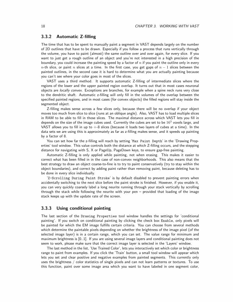
3.3.2 Automatic Z-filling
The time that has to be spent to manually paint a segment in VAST depends largely on the numberof 2D outlines that have to be drawn. Especially if you follow a process that runs vertically throughthe volume, you have to paint (almost) the same outline over and over again, for every slice. If youwant to just get a rough outline of an object and you’re not interested in a high precision of theboundary, you could increase the painting speed by a factor of n if you paint the outline only in everyn-th slice, or paint n slices at a time. In the first case, you get gaps of n − 1 slices between thepainted outlines, in the second case it is hard to determine what you are actually painting becauseyou can’t see where your color goes in most of the slices.
VAST uses a third method. It supports automatic Z-filling of intermediate slices where theregions of the lower and the upper painted region overlap. It turns out that in most cases neuronalobjects are locally convex. Exceptions are branches, for example when a spine neck runs very closeto the dendritic shaft. Automatic z-filling will only fill in the volumes of the overlap between thespecified painted regions, and in most cases (for convex objects) the filled regions will stay inside thesegmented object.
Z-filling makes sense across a few slices only, because there will be no overlap if your objectmoves too much from slice to slice (runs at an oblique angle). Also, VAST has to load multiple slicesin RAM to be able to fill in those slices. The maximal distance across which VAST lets you fill independs on the size of the image cubes used. Currently the cubes are set to be 163 voxels large, andVAST allows you to fill in up to +-8 slices (because it loads two layers of cubes at a time). In thedata sets we are using this is approximately as far as z-filling makes sense, and it speeds up paintingby a factor of 8.
You can set how far the z-filling will reach by setting ’Max Paint Depth’ in the ’Drawing Prop-erties’ tool window. This value controls both the distance at which Z-filling occurs, and the steppingdistance for navigating with S, X or PageUp, PageDown keys, to ensure gap-free painting.
Automatic Z-filling is only applied while painting, not when erasing. This makes it easier tocorrect what has been filled in in the case of non-convex neighborhoods. This also means that thebest strategy to draw an object coarse-to-fine is to try to paint conservatively (try to stay within theobject boundaries), and correct by adding paint rather than removing paint, because deleting has tobe done in every slice individually.
’Z-Scrolling During Paint Stroke’ is by default disabled to prevent painting errors whenaccidentally switching to the next slice before the paint stroke is finished. However, if you enable it,you can very quickly coarsely label a long neurite running through your stack vertically by scrollingthrough the stack while following the neurite with your pen – provided that loading of the imagestack keeps up with the update rate of the screen.
3.3.3 Using conditional painting
The last section of the Drawing Properties tool window handles the settings for ’conditionalpainting’. If you switch on conditional painting by clicking the check box Enable, only pixels willbe painted for which the EM image fulfills certain criteria. You can choose from several methodswhich determine the paintable pixels depending on whether the brightness of the image pixel (of theselected image layer) is in a certain range, which you can set. The value range for minimum andmaximum brightness is [0..1]. If you are using several image layers and conditional painting does notseem to work, please make sure that the correct image layer is selected in the ’Layers’ window.
The last method in the list, ’Use Trained Color’, lets you interactively set which color or brightnessrange to paint from examples. If you click the ’Train’ button, a small tool window will appear whichlets you set and clear positive and negative examples from painted segments. This currently onlyuses the brightness / color statistics of single pixels and can not learn patterns or textures. To usethis function, paint over some image area which you want to have labeled in one segment color,

3.4. SEGMENTS 19
select that segment color and click ’Add Positive from Selected Segment’. Then use a differentsegment color to label some image area which should be excluded from painting, make sure thatsegment color is selected, and click ’Add Negative from Selected Segment’.10 Then set the ’Method’to ’Use Trained Color’. Subsequently VAST will only paint over pixels which have brightness or colorsimilar to the positive example pixels. If you add positive or negative examples several times, the newexamples will be added to the set of already defined examples, until you clear the training data.11
3.4 Segments
3.4.1 Picking segments
You can select the segment color to paint with in the ’Segment Colors’ tool window by clicking onit in the tree view. You can also pick any color you see in the segmentation layer by using the pipettetool. To do this hold down the SHIFT key and click on the segment you wish to select. This makesis very easy to switch between segment colors while painting. Alternatively you can use the Pipettemode which you can select in the main toolbar. If you have several segmentation layers, you can pickcolors in a different segmentation layer as well, and VAST will automatically make that segmentationlayer active. If you hover over segment colors in the main window when in picking mode, VAST willdisplay the name of the segment as a tooltip. If the segment is in a different segmentation layer, thename will be shown in brackets together with the layer name.
3.4.2 The segment hierarchy
VAST can arrange segments in a tree-like hierarchy. This means that each segment can haveother segments as children, which can themselves have children, and so on. VAST also allows youto collapse and expand parts of the tree dynamically, so that you can quickly switch between avisualization which shows a whole branch of the tree in the same color or individual sub-branches inindividual colors. For example, if all spines of a spiny dendrite are labeled as sub-objects (children)of the dendritic shaft, one can instantly flip between a display in which the whole dendrite has thesame color, or each spine has a different color, by opening and closing the dendritic shaft folder.Segments can also be used as folders to group segments, for example to classify labeled objects. Youcan use tags to designate certain segments as folders, to help external analysis (see section 3.4.10).The grouping can also be applied when segmentations are exported.
Segment hierarchies are visualized and edited in the ’Segment Colors’ tool window. This toolwindow uses a ’tree view control’, similar to the navigation pane of a windows explorer window,which makes usage very intuitive. Most advanced functions can be found in the tool window’s menu,which opens either by clicking the ’Menu’ button or right-clicking into the tool window.
3.4.3 Re-ordering and moving segments in the tree
To re-order the segments, simply drag and drop them with the mouse. You can only select anddrag one segment at a time, but if the segment has children the whole branch will be moved(including all children). Please note that to make a segment the first child of another segment, youhave to drag it to the right side of the tool window, right of the new parent segment. The newparent segment will then be highlighted in blue, instead of the black line indicating the target spacebetween two segments. You can move any segment, with exception of the ’Background’ segment.The Background segment can also not have any children.
10VAST only scans the pixels in the selected segment color which are in the currently displayed slice and region.11Internally VAST uses a 643 HSV cube for example storage and color space mip maps for generalization.

20 CHAPTER 3. WORKING WITH VAST
Because it can be cumbersome to move hundreds of items from one folder to another one by one,VAST currently supports two functions ’Make all siblings children’ and ’Make all children siblings’which can help in certain situations (see section 3.4.7).
3.4.4 Collapsing and expanding tree branches
You can collapse and expand tree branches, which are displayed in the same way as folders andsubfolders are in the Windows explorer, by clicking on the little ’+’ or ’-’ sign left of parent segments.When you collapse a folder, all its children will be displayed in the same color as the parent. If youpick a segment color from the segmentation layer by shift-clicking, and the selected segment is in acollapsed folder, the folder will be automatically expanded to show the native color of the segmentyou selected. In addition the context menu has two functions to set the collapse state of all subfoldersof the selected segment at once, under ’Expand / Collapse Child Folders’. Also see section3.4.10.
3.4.5 Using anchor points
Each segment has an ’Anchor Point’ stored with it. This is an XYZ coordinate vector which indicatesthe location of the segment in the image stack. Initially the anchor point is set to the location at whichthe segment is painted first. You can jump to the anchor point by right-clicking on a used segment inthe ’Segment Colors’ tool window and selecting ’Go To Anchor Point’ from the context menu.You can quickly jump to the anchor point of the selected segment by pressing the ’Home’ key or ’G’(for ’go to’).12 You can also set the anchor point of the selected segment to the current view location(as indicated by the center cross) by selecting ’Set Anchor Point’ from the context menu. Youwill have to confirm this action in a pop-up window to prevent accidental setting of anchor points.
3.4.6 Adding new segments
The context menu of the ’Segment Colors’ tool window provides several functions to add moresegments to the selected segment layer. You can add a segment as next sibling or as a child of theselected segment. ’Add 10 Segments’ will add 10 segments immediately after the selected segment.’Add Skeleton Segments’ adds a set of child segments to the selected segment which can be usedfor rudimentary skeletonization. I have not found this function particularly useful though.
The most sophisticated way to add segments is ’Add Named Segments ...’, which lets youspecify a naming scheme and add multiple named segments at the desired target location in thesegment tree. VAST will attempt to guess a naming scheme from the name of the currently selectedsegment.
You can change the name of any segment in the same way as file names are changed in theWindows Explorer – click a selected segment name a second time, then rename it.
3.4.7 Helper functions for arranging segments
Under ’Arrange’ in the context menu you can find two useful functions to move many segments atonce. ’Make All Siblings Children’ will move all siblings of the selected segment into its folder(make them children of the selected segment). ’Make All Children Siblings’ moves all childrenof the selected segment out of its folder and makes them siblings. Be careful with these functionsbecause currently there is no ’Undo’.
12If you pressed the ’Home’ key accidentally and want to go back to where you were, you can select the previouslocation from the drop-down menu in the ’Coordinates’ tool window.

3.4. SEGMENTS 21
3.4.8 Select recently selected segments
Under ’Select Recently Selected’ in the ’Segment Colors’ tool window’s context menu youcan find a list of the segments you had recently selected. You can click on one of the listed segmentsto select it again.
3.4.9 Global operations: Deleting and welding segment subtrees
The context menu of the ’Segment Colors’ tool window provides two functions which changesegment numbers in the whole segmentation layer, one to delete segments from the segmentationlayer (’Delete Segment + Subtree’) and one to weld all children in a subtree to its parent (makingthem all the parent color, while removing the child segment numbers), ’Weld Segment Subtree’.
Deleting and welding segments is actually more difficult than it seems because it involves travers-ing the whole segmentation data set and inspecting every single painted voxel. When you chooseto delete the selected segment and its children, VAST will actually have to not only set all voxelswith those segment numbers to 0, but also renumber all the other voxels so that the used segmentnumbers will have no ’gaps’ (all segment numbers between 0 and n are used).
’Welding’ will merge a whole segment subtree into a single segment (the parent). For this VASTneeds to renumber all voxels with segment numbers of children of the selected segment to thesegment number of the selected segment, and also, similar to when deleting, renumber the othersegment voxels so that the resulting segmentation is free of segment number gaps.
Because these functions change almost the complete segmentation and VAST is designed sothat the opened segmentation file is not changed, it basically has to copy almost the completesegmentation data to the temporary cache file. Depending on what segmentation you are workingon this can take a lot of time, RAM and disk space. Also it will change the internal ID numbers ofthe segments, so please think twice before using these functions in case you are relying on absolutesegment IDs in your analysis. These functions are also not well tested; please report any bugs youmight encounter.
3.4.10 Segment tags
Each segment can have a ’Tag’ which you can select in the ’Segment Colors’ context menu under’Tags’. A tag is a number between 0 and 15 which can indicate the type of the segment. Thetag value is exported with the Segment Colors text file and can be used to help external analy-sis. By default the tag of all segments is 0. VAST uses tag 1 to indicate that the segment is a’Folder Segment’, which is not a labeled object by itself but rather a folder which contains otherfolders and objects. This information can be used to collapse all objects, but expand all folders – se-lect ’Expand Only Segments Tagged as Folder’ under ’Expand / Collapse Child Folders’in the ’Segment Colors’ tool window context menu.
Segments which have a tag that is not 0 will have an icon with a colored frame in the SegmentColors tree window. Folder segments have a gray frame.
3.4.11 Editing the color of a segment
The color and pattern of any segment can be changed. Right-click on a segment and go to the sub-menu ’Colors’ of the context menu, then choose the desired option. Each segment has a primarycolor, a secondary color, and a pattern that is used to blend between them. You can also randomizethe colors of all segments of the selected subtree (the selected segment and all its children), or setthe primary or secondary color or pattern of all segments of the selected subtree the same.13
13If the Background segment is selected, these functions will apply to all segments in the segment layer (except theBackground segment).

22 CHAPTER 3. WORKING WITH VAST
Please remember that by collapsing segment folders you can quickly and reversibly switch thedisplayed color of a segment to the color of the collapsed parent, without the need to change thecolor of all children individually.
3.4.12 Exporting segment metadata
The entry ’Save Segment Colors...’ in the context menu lets you export the metadata of thesegments to a text file, which you can then for example parse with MATLAB to extract colors,hierarchies, names, anchor points etc. of the segments for analysis. A Matlab script which can parsethese files is included in the supplementary package (scanvastcolorfile.m). The format of thetext file is described at the beginning of the text file itself:
1 ID number of the segment2 Flags field of the segment as 32-bit value3-6 Primary color as red, green, blue, pattern17-10 Secondary color as red, green, blue, pattern2 (unused)11-13 XYZ coordinates of the segment’s anchor point (in voxels)14-17 IDs of parent, child, previous and next segment (0 if none)18 If the segment is collapsed into a folder, this is the folder ID19-24 Segment bounding box (may be incorrect if voxels were deleted)25 Segment name as text in ” ”
Table 3.1: Columns of the segment metadata text file
The ’Flags’ field uses the following bits: 0: isused, 8: isexpanded, 16,17: isselected (1: selected,2: in child group of selected)
3.4.13 Segment information
’Segment Information ...’ in the context menu opens a window which shows you the internalinformation associated with the selected segment. You can use this information to count children ofthe segment, get its internal ID or other parameters. Getting the segment info of the ’Background’segment returns statistics for the whole segmentation layer. The text can be copy-pasted if needed.
3.4.14 Searching for a segment with a given name or ID
At the top of the ’Segment Colors’ tool window there is an edit field which can be used to findsegments. As you type or paste a text string into this field, VAST will select the next segment (afterthe selected segment in depth-first search order) the name of which contains the typed sub-string.The edit field is case-sensitive. If there is more than one segment which contain this sub-string, youcan click on the magnifying glass right of the text edit field to go to the next segment that matchesyour text. The F3 key has the same function, provided that the segment tree sub-window of the’Segment Colors’ tool window is active.
You can also search for a segment with a particular ID. To do this, type an opening bracket [
into the find edit field, followed by the ID number (internal segment number) you are looking for.
3.4.15 The ’Collect’ tool
The ’Collect’ tool (’Collect Segment Mode’) can be selected in the toolbar by clicking the icon withan arrow pointing at a folder. When in Collect mode, segments you click will be moved in thesegment tree to become children of the currently selected segment. This can be useful to quickly

3.5. SAVING SEGMENTATIONS 23
classify different objects into different types. Simply make a folder segment for each type, select it,and click on the objects in the image that are of that type with the ’Collect’ tool.
Using this tool is a bit dangerous because there is no Undo. If you click the wrong object itmight be difficult to remember where it came from and there is currently no easy way to ’move itback’. Secondly, when an segment is moved, all its child segments are moved with it, but not itsparent(s). So if you are dealing with objects which consist of several parts, make sure that you movethe parent segment of the object and not only a side branch of its tree.
3.5 Saving Segmentations
Important: VAST DOES NOT SAVE AUTOMATICALLY while you paint. Your tracings will be heldin RAM and/or a cache file on disk until you explicitly save them. If you open a segmentation froma .VSS file and work on it, the file will not be changed unless you explicitly tell VAST to save thechanges you made to the opened file by selecting ’Save Segmentation’ from the main menu. Ifyou want to keep the previous version and save to a new file, use ’Save Segmentation As ...’instead. VAST will then take all data from the opened file, the RAM cache, and the segmentationcache file, and combine them into a new file on disk.
We have had cases in which people had VAST open for several days without saving and lost alot of work when the computer crashed. Please save your work once in a while.
3.5.1 Save Segmentation As Special
’Save Segmentation As Special ...’ provides you with two functions to save your current seg-mentation to a new file in a modified way. First, you can choose to save only the selected segmentor subtree of the current segmentation to a new file. Alternatively, you can change the resolutionof your segmentation and adjust the canvas size on which the saved segmentation will open (this iscurrently only supported when saving all segments).
To save only the selected segment or the selected segment and its child tree to a new segmenta-tion, select that option from the drop-down list and press ’Save’. Please be aware that the internalIDs of the segments in the new segmentation file will be changed to maintain a gap-free list of IDsfrom 1 to n for n segments.
The settings in the lower part of the dialog provide limited functionality to adjust the resolutionof the saved segmentation and target canvas size.
Normally VSS files only open on top of an image stack of the same size in voxels. You can usethis function to save an existing segmentation so that you can open it on a stack which has slightlydifferent size and/or is scaled up or down by a power of two.
Currently the saved segmentation will stay aligned to the upper, left, top corner of the stack.Also, only powers-of-two scaling is possible. If you want to translate the segmentation to a differentlocation or scale in the target stack, you’ll have to export the segmentation as an image stack, modifythe images accordingly, and re-import.
3.6 Segmentation Merging
If you have two or more (for example partial) segmentations (.VSS files) of the same image stackyou can merge them into a single segmentation. For this, first open one of the segmentations youwant to merge in VAST, and then select ’File / Merge Segmentations in ...’ from the mainmenu, and choose the .VSS file(s) you would like to merge in with the opened segmentation. Duringmerging, VAST will add the selected .VSS files to the current segmentation. VAST lets you choosewhether you want to change segment IDs of the merged-in data so that they do not overlap withexisting segments, or keep segment IDs of the imported file (then only segments with new IDs will

24 CHAPTER 3. WORKING WITH VAST
be added to the segment list, and segments with existing IDs will extend pre-existing regions). Youcan also choose whether to put new segments into a separate folder, and whether or not to overwritepre-existing voxels or only write into empty voxels. You can select several .VSS files at once formerging, which will then be added one-by-one.
VAST does not save the merged segmentation automatically nor does it change any of thesegmentation files. It will generate the merged segmentation in the segmentation cache, and if it doesnot fit in RAM it will end up in the temporary segmentation file. You will have to save the resultingmerged segmentation if you want to keep it, for example via ’File / Save Segmentation As ...’from the main menu. Please make sure that there is enough space on the drive used for the diskcache.
3.7 Importing Segmentations From Image Stacks
VAST can import segmentations from image stacks, either generating a new segmentation or mergingwith a previously loaded segmentation.
Just like the image files generated during segmentation exporting (see section 3.8 below), theRGB values of the image pixels should encode the segment numbers (the least significant 8 bits(0..7) are in the blue channel, bits 8..15 in the green channel, and bits 16..23 in the red channel).Please keep in mind that VAST can currently only handle 16-bit segmentations, so the red channelshould always be 0. However, because of the requirement to have gap-free segment numbers insegmentations, VAST will scan all images for existing segment numbers and renumber them asnecessary if it finds gaps or channels are used differently than expected.
To import, select ’File / Import Segmentation from Images ...’ from the main menu.VAST will ask you to select one or several image files of the image stack you want to import. Thenit will open a dialog where you can specify the parameters for segmentation importing.
File name(s):You have to specify a name template for all image files in the stack. This has to be a C++ formatstring (as it is used by printf()). This means that numbers which specify the slice, column androw coordinates in the file name have to be replaced by codes like ’%d’ (integer number) or ’%04d’(integer number with zero-padding to 4 digits). VAST will then fill in those numbers for each image.For more information about format strings, please refer to a C++ manual or ask the internet. Youalso have to specify the order and the value limits for the parameters of your file name template, todefine the range of names of all the images or image tiles in your stack.
Image Parameters:Here you can rotate and flip the images if necessary, and tell VAST where to put them into thecurrently opened volume. The ’Tile Size’ is extracted from the image file you selected, but you canadjust it here too. The ’Start coordinates’ are currently not allowed to be negative. Please crop yourimages prior to importing if necessary.
Segmentation Image Preprocessing:The option ’Force 8 bit Graylevel’ tells VAST to interpret the images as single-channel 8 bitimages, by only using the least-significant 8 bits of the image data. This can help in cases where theloaded images are supposed to be 8 bit graylevel images but are encoded or interpreted as RGB orRGBA color images.
Segment Label Parameters:If you have a segment metadata file for the imported segmentation stack (same format as the filewritten in section 3.4.12) you can provide it here. The options below specify how VAST should deal

3.8. EXPORTING IMAGE STACKS 25
Figure 3.4: Export dialog
with the segments in the imported stack. If you are importing into a previously loaded segmentation,you can either keep the imported segments separate by renumbering and appending them to theexisting segments, or merge the imported segments which have already existing segment IDs with theexisting ones. New segments will be appended. If you use the option ’Merge with existing segments;Renumber unknown segments’ together with a metadata file, the hierarchy in the metadata file willbe ignored.
Voxel Combination Parameters:If ’Overwrite existing non-zero voxels’ is checked, imported non-zero voxels will overwrite existingnon-zero voxels. If it is not checked, VAST will keep existing non-zero voxels and ignore importednon-zero voxels at the same place.
Similar to segmentation merging, VAST will not save the segmentation after importing automat-ically. You can do that yourself after importing, using File / Save Segmentation As ...’ fromthe main menu.
3.8 Exporting Image Stacks
Exporting EM volumes and/or segmentations as image stacks can be useful to generate slice anima-tions, to transfer data to other programs like the Fiji 3D viewer, or to process your results furtherexternally.
To export (parts of) the image stack and/or segmentation stack as a stack of image files, select’File / Export ...’ in the main menu. The dialog shown in Figure 3.4 will pop up. You canexport EM image stacks, segmentation image stacks, and screenshot image stacks. You can specifya region of the data set to be exported, and a resolution (mip level) for the images. You can alsoexport a data region which is too large for storing the whole slice in a single image as a tiled set ofimages.
Export as:Choose here if you want to export an image stack as a single-tile stack (one tile per slice) or amulti-tile stack (a grid of image tiles per slice). For the second option you can define the tile size tobe used.

26 CHAPTER 3. WORKING WITH VAST
Region to export (Specify coordinates at full resolution):This defines the region of the stack that should be exported, for all three targets (Screenshot, EM(image) data, Segmentation). By default it is set to the full stack. You can restrict the export regionhere. X is the horizontal axis in the slice, pointing rightwards; Y is the vertical axis in the slice,pointing downwards on the screen, and Slice (Z) defines the range of slices that should be exported.The first and second columns of the edit fields let you define start and end of the region for eachaxis, the third column defines the size of the exported region (edit fields change each other to stayconsistent).
The ’Full’ button will set the values back to the full extent of your stack.The ’BBox’ button sets the region to the bounding box of the currently selected segment. You
can use this function to define a cut-out region from a painted segment14, or use a new segmentand just paint the upper left top and lower right bottom corners of the cutout region, select it anduse the ’BBox’ button to set the export region.
The ’Center’ button will center the exported region to the current coordinates in the mainwindow. You can for example use this in the following way: First move the image in the mainwindow to the location you want to export. Then open the export dialog and specify the size ofthe image you want to export in pixels, in the third column of the ’Region to Export’ section, forexample to 1024, 1024, 1 for one image with size (1024,1024). Then click ’Center’ to place theexport region at the currently viewed location.
Under ’Resolution:’ you can select at which mip level you want to export. VAST does notsupport arbitrary scaling, but can export image stacks at its native mipmap scales (which are powersof two). You can also subsample the stack by slices (every nth slice).
Below you can see the image size resulting from your settings and an estimate of the (raw) datasize that will be exported. Compressed image formats like .PNG can however produce much smallerfile sizes, depending on the image content.
Screenshot target:If you want to export a stack of ’screenshots’ how the images look in the main window of VAST,enable the checkbox ’Export Screenshot as’. VAST will reproduce the pattern, blending andtinting settings as they are currently set in the main window in the exported ’screenshots’. Select atarget image format and filename prefix / location.
EM data target:This saves a stack of (EM) image data from the selected layer. You can specify the target format,filename prefix and location.
Segmentation target:This saves the segment IDs of the currently selected segmentation layer or part of it as an imagestack. The segment ID of each pixel (a 16-bit number) will be encoded in the color of the pixel inthe exported image. Bits 0-7 will end up in the blue channel and bits 8-15 will end up in the greenchannel. The red channel will currently stay 0.
3D models target:This function is currently disabled because it is not fully implemented yet. For now please use Vast-Tools to export 3D models of segmentations (see section 4.2).
When you are done setting up the parameters for the export, press ’Export’ and VAST will startexporting the image stack or stacks (VAST can export more than one target at the same time).
14Note that the bounding box is not always correct, in particular if you delete parts of what was painted before, thebounding box will not shrink.

3.9. THE 3D VIEWER 27
3.9 The 3D Viewer
VAST now contains a simple 3D viewer which lets you view a region of your image stack in 3D. Toopen the 3D viewer, select ’Window / 3D Viewer’ in the main menu of VAST.
To use this you first have to set up the 2D view so that it shows what you want to see in 3D,and then select ’View / Update’ in the menu of the 3D Viewer window to load the data. Theblock shown will be more or less centered around where the current 2D view is located (the centercross location), and use the current 2D resolution (mip level). The transparency in the 3D view isderived from the pixel brightness. You can choose to either ’Show bright’, ’Show dark’ or apply’Constant’ opacity by selecting the corresponding option under ’Transparency’ in the windowmenu. To see the effect of the selection, update the data by selecting ’View / Update’ in the menuof the 3D Viewer window.
Assume for example you have an EM stack and a segmentation loaded in VAST, and you wantto see just one segmented object with its children in 3D. For this, adjust the 2D view so that onlythat segmented object is shown and everything else is black: Switch off the EM layer and ’Alpha’,enable and maximize ’SelAlpha’, and select the parent segment of the segments you want to showup in 3D. Center the 2D view to the segment of interest and zoom to the desired resolution. Then,in the 3D Viewer window, make sure that ’Show bright’ is selected under ’Transparency’ in thewindow menu, and select ’View / Update’. After the data is loaded, just your segmented object(s)should show up in the 3D viewer.
You can zoom the 3D view in and out with the mouse wheel and rotate it in all three axes bydragging with the mouse (the mouse cursor shows which rotation axes will be affected, dependingon where the mouse cursor is in the window).
Further options include changing the background color, displaying a line cube around the datablock, and choosing from two different block sizes.

28 CHAPTER 3. WORKING WITH VAST

Chapter 4
The VastTools Matlab Toolbox
VAST includes an API through which it can communicate directly with client programs, using aTCP/IP connection. The Matlab script VastTools, which is included with VAST Lite, uses this API toprovide users with a number of additional tools for VAST, including target lists, 3D surface exportingand measurement functions. It can be found in the vast_package.zip file. Since VastTools is aMatlab script, users can extend the interface with their own functions. Documentation of the VASTAPI is provided in Appendix B.3.
4.1 Getting started with the VastTools Matlab Toolbox
To start the toolbox, open vasttools.m in Matlab and run it. If Matlab asks, change the currentdirectory. A small window should pop up with a menu, message field and cancel button.
Before you can use any of the functions of the toolbox you have to connect VastTools to aninstance of VAST which is currently running. First, in VAST, you must enable the Remote ControlAPI Server. Select ’Window / Remote Control API Server’ in the main menu of VAST. In the toolwindow which then opens, enable a TCP/IP port for communication by clicking the ’Enable’ checkbox in the upper left corner. If you are running VAST and VastTools on the same computer, youcan use the standard settings (IP 127.0.0.1 and port 22081 on both the VAST and Matlab side).If you are using VastTools a lot and do not want to enable the API every time manually, you can seta flag in the Preferences to have it enabled automatically when VAST starts (see section 2.2.2).
Then, in VastTools, connect to VAST by selecting ’Connect / Connect to VAST’ in the main menuof the VastTools window. If the menu item ’Connect / Connect to VAST’ changes to ’Disconnect /Disconnect from VAST’ you are connected. The message log in the VAST Remote Control Serverwindow will also show when a remote connection has been accepted. In case you are using a differentIP or port, for example because VAST and VastTools run on separate computers, you can set the IPaddress and port to use under ’Connect / Connection Options’ in the VastTools main menu.
Once connected, you can use the different functions of the VastTools toolbox by selecting fromthe main menu of the VastTools window in Matlab.
4.2 Exporting 3D Models
3D model exporting generates surface meshes of the painted voxelized segmentation in VAST, andsaves the resulting meshes in Wavefront OBJ files which are widely supported by 3D renderingand animation programs. VastTools uses Matlab’s isosurface function to generate the meshes.Typically, it will generate surface meshes in parts of the volume to limit memory usage, and then gluetogether the mesh pieces to generate the final objects. The exporter also saves a .MTL file for each
29

30 CHAPTER 4. THE VASTTOOLS MATLAB TOOLBOX
Figure 4.1: Exporting from VAST using VastTools
OBJ file which defines the material properties (color) as defined in VAST. You can also measure thesurface area of all exported objects and save the results to a text file.
If you select ’Export / Export 3D Surfaces as OBJ Files ...’ from the main menu in VastTools, adialog window will pop up in which you can specify all the parameters for the export. Once you click’OK’ the exporting will start and run until finished or until you press ’Cancel’ in the main VastToolswindow. This will export objects of the selected segmentation layer.
The following parameters for the export can be set:
Render at resolution:Here you can select the mip level at which the surfaces should be generated. Lower mip levels willresult in more detailed models, but also generate larger OBJ files with more triangles and take longerto process. Models and surface computations will be automatically scaled to compensate.
Use every nth slice:If you want to reduce the resolution in Z you can do so by skipping slices. If you set this value to2, every second slice will be used, if you set it to 3, every third, and so on. Models and surfacecomputations will be automatically scaled to compensate.
Render from area:This specifies the region of the current volume in which you want to generate surface models. Bydefault the region is set to cover the whole volume, but you can change the values to cover a smallerregion if needed. These values are always specified at full resolution, no matter which mip level isset in the ’Render at resolution’ selector.
’Set to full’:Push this button to set the area boundaries to the full extent of the data set opened in VAST.
’Set to selected bbox’:This sets the render area to the combined bounding box of the segment selected in VAST and all its

4.2. EXPORTING 3D MODELS 31
children. CAUTION: The segment bounding boxes are currently not always correct. For example, ifyou erase voxels you previously painted in VAST, the bounding box will not shrink.
’Set to current voxel’:This button sets the render area to a single voxel, the current center voxel set in VAST. Use togetherwith ’Extend to current voxel’ to define a target area by its corner points.
’Extend to current voxel’:This button extends the boundaries of the render area to include the current center voxel set inVAST. Use together with ’Set to current voxel’ to define a target area by its corner points.
Voxel size (full res):These fields will be filled in automatically by the values provided by VAST. The voxel size is used toscale your models correctly. You can override these values manually by entering different values intothe edit fields.
Scale models by:Additional scaling factors for your models. By default these factors are set to 0.001 (1/1000) in alldirections to convert the units from nanometers to micrometers.
Model output offset:By default the models will be placed so that the upper left corner of the exported region is at theorigin (0,0,0). You can provide a constant offset here if you want to move the models somewhereelse.
Processing block size:As mentioned above, models are exported in smaller blocks and then glued together; this specifiesthe block size. A smaller block size will reduce memory consumption and may increase the speed ofisosurface computation, but will increase the processing time needed for glueing model parts together.Changing the block size should only have an effect on memory consumption and processing speed,not on the exported models.
Export what:Here you can select whether you want to export models of all segments, or of a selected branch,and you can choose whether to export all segments individually or glue them together as they arecurrently displayed in VAST (by selecting a parent segment, and collapsing and expanding folders inVAST). This information will be read from VAST when you press OK, so you can make adjustmentsin VAST while the VastTools export dialog is open.
File name prefix:All OBJ file names, and also the names of the exported objects, will start with this prefix string.
Object Colors:Here you can select between ’Object colors from VAST’ (the default) and ’Object volumes as JETcolormap’. The latter only works if you previously computed object volumes (under ’Measure /Measure Segment Volumes ...’).

32 CHAPTER 4. THE VASTTOOLS MATLAB TOOLBOX
Target folder:All generated OBJ and MTL files will be stored to this target folder. Use the ’Browse...’ button toselect a different folder.
Include Vast folder names in file names:If enabled, the VAST folder names of the segment hierarchy will be added to all OBJ file names,and also the names of the exported objects. This makes it easy to select and process subsets of theobjects based on their names. However, please keep in mind that the length of file names can belimited, depending on your file system, and names which are too long can lead to problems.
Invert Z axis:In enabled, the models will be mirrored so that they lie below the z = 0 plane. This reflects theactual shape of the objects in the tissue, if slices are counted up as the are cut off the surface of ablock.
Write 3dsMax bulk loader script to folder:If enabled, a small file called ’loadallobj_here.ms’ will be saved to the target directory. This is a3dsMax script which, if executed in 3dsMax, will batch-load all objects in the same directory. Thisis very useful if you are working with many object files.
Close surface sides:If enabled, meshes will be closed at the sides where they exit the extraction region.
Skip model file generation:Enable this option if you just want to measure model surface area and not generate OBJ files.
Save surface statistics to file:If this is enabled, the export script will also compute the surface area of each exported object (bysumming up the triangle surface areas) and save the result to the text file with the provided name.This file will always be stored in the same folder as the OBJ files (the target folder), so please giveonly a file name in the text field, not a file name with target path. Computing the surface area willtake additional time, so disable it if you don’t need it.
4.3 Exporting Projection Images
The ’Export Projection Image’ tool allows you to generate 2D projection images in which yourmicroscopic image stacks and/or segmentations are projected along a cardinal axis. This is forexample useful to generate ’renderings’ of your segmentation or a Z-projection of part of a confocallight microscopic image stack. You can also use these projection images as ’Simple Navigator Images’,see section 4.5. The following parameters can be set in the export dialog:
Render at resolution:Sets the mip level at which the projection image is rendered. This affects the resolution of the sourceimages in X and Y, but not Z.
Use every nth slice:To reduce the resolution in Z (and speed up rendering of very large stacks) you can skip slices if youset this to an integer value larger than 1.

4.3. EXPORTING PROJECTION IMAGES 33
Figure 4.2: Example stack projection images with simulated shadows, generated with VastTools inMatlab
Render from area:This determines the XYZ block from which the image will be generated. You can use the buttons’Set to current voxel’ and ’Extend to current voxel’ together with moving the center cross in VASTto different locations to help you set up a source area. ’Set to full’ sets the area to the completevolume, and ’Set to selected bbox’ sets it to the combined bounding box of the selected segment andits children. CAUTION: The bounding boxes associated with each segment in VAST are currentlynot always correct. For example, if you erase voxels you previously painted in VAST, the boundingbox will not shrink.
Projection axis, stretching:Select here along which cardinal axis you would like to project and from what side (which side shouldbe in front in the image), and whether the resulting image should be stretched in Z (for projectionsalong the X or Y axis) if the slice thickness is different from the pixel size. The stretching will bedetermined by the voxel size of your image stack as set in VAST (see section 3.1.4).
File name, Target folder:Enter the target file name and location here. The projection image will be saved there after generationif ’Save to file’ is enabled.
Segmentation preprocessing:Select here how you want to use the segmentation for the projection image. This determines whichparts of the segmentation are used, and for the ’Screenshots’ image source whether the segmentsshould be colored as displayed in VAST (collapsed) or in their individual native colors (uncollapsed).
Expand segments by n pixels:Makes your segmented regions larger. Useful when using the segmentation as a mask.
Blur edges by n pixels:Blurs the edges of the segmentation to smooth out the projection image.

34 CHAPTER 4. THE VASTTOOLS MATLAB TOOLBOX
Image source:Select here what you want to use as source images for the projection image. Select ’Screenshots’ ifyou want to use images as they are shown in VAST (using all brightness and contrast settings, layerblending and tinting, segmentation transparency, patterns, etc). A faster option is to just use theprimary colors of either the selected or all segmentation layers.
Background color:Color shown behind the image stack where the stack is transparent
Opacity source:Determines which parts of each image plane should be rendered opaque for the projection image.Choose to render only segmented areas, only unsegmented areas, or all (Constant). You can also usethe pixel brightness of screenshots to define opacity, and either render bright or dark pixels opaque.
Object opacity [0..1]:Multiplier for the opacity of areas selected in ’Opacity source’. Use a value between 0 (transparent)to 1 (fully opaque).
Blending mode:Select here whether you want to alpha-blend images with the selected opacity map, add all images,or do a maximum or minimum value projection.
Use shadows, Shadow cone angle:Enable the check box if you want to include (fake) shadows in the rendering. The shadow cone angledetermines how much the shadow spreads out (by means of an image blur filter) from slice to slice.
Depth attenuation (far brightness) [0..1]:If you set this to values below 1, slices which are further away in the stack will be darkened. Thiscan support the impression of depth in the resulting projection image.
Normalize projection image:If enabled, the brightness of the final projection image will be adapted so that it uses the wholebrightness range (without changing color hue).
4.4 Measuring
VastTools provides several functions to measure objects labeled in VAST.
4.4.1 Measure Segment Volumes
This function can count the number of voxels of different segmented objects in a source area, andsave the results to a text file. Parameters in the setup dialog of this function are similar to thoseof exporting 3D models and measuring surface sizes (see section 4.2 above). Please make sure thatthe voxel size you use is correct and that you cover the complete area you want to measure to getcorrect results.
4.4.2 Measure Segment Lengths
This function is not yet implemented.
4.5. SIMPLE NAVIGATOR IMAGES 35
4.4.3 Measure Segment Surface Area
Since this function relies on a surface mesh to estimate the surface area, it is part of the ’Export 3DSurfaces as OBJ Files’ function (see section 4.2). You do not have to generate model files if youjust want to measure surface area (check ’Skip model file generation’ in the parameter setup dialog).Please make sure that the voxel size you use is correct and that you cover the complete area youwant to measure to get correct results.
4.4.4 Euclidian Distance Measurement Tool
This will open a dialog in which you can make simple 3D distance measurements between points inVAST.
First, go to a location in VAST (use the center cross). Then, in VastTools, click the ’Get’ buttonnext to the first coordinate to read the current location from VAST. Then go to the other locationand click ’Get’ next to the second coordinate. The distance between the two locations will show upas a distance in voxels, and in nanometers.
You can easily jump back to the first and second coordinate in VAST by pressing the ’GO!’button.
Make sure you are using the right voxel size to get accurate nanometer measurements. Click’Update’ to read the current voxel size from VAST. To change the voxel size, please set the voxel sizein the .vsv file used in VAST. To do this go to ’Info / Volume Properties ...’ in VAST and changethe voxel size (see also section 3.1.4). Then click ’Update’ in the VastTools Euclidian DistanceMeasurement Tool.
You can copy the values in the edit fields in the Euclidian Distance Measurement Tool to pastethem into different programs, but editing these values directly will currently not work.
4.5 Simple Navigator Images
Simple Navigator Images provide a means to navigate in an image stack using a projection image.After you rendered a projection image in VastTools using ’Export / Export Projection Image ...’(see section 4.3), you can generate a clickable Simple Navigator Image from it. Select ’Navigate /New Simple Navigator Image From Last Projection Image ...’. A new window should pop up whichshows the last projection image together with a menu and toolbar. Use the arrow tool to click ona segment anywhere in the projection image to have VAST move to that location in your data set.The magnifying glass tool and the hand tool can be used to zoom and pan the image respectively.
Use ’File / Save Simple Navigator Image ...’ to save this Simple Navigator Image to a file whichyou can open again later. You can have several Simple Navigator Images open at the same time, forexample projection images along several axes, and navigate using all of them.
4.6 Target Lists
Target lists can store the current view coordinates, zoom level and selected segment together withcomments. You can add the current view in VAST to the target list by clicking the ’Add currentVAST location’ button. To move the view in VAST back to a stored location, click on the ’GO!’field of the row in the table. You then have to make VAST the active window to see the change.
Functions to delete, rearrange and add separator lines to the list are provided in the Edit menu.You can save target lists to a file and load them back later. You can have several target lists openat once and cut/copy/paste between them. You can also select the list, or part of the list, and copy(Ctrl-C) and paste (Ctrl-V) the contents into other programs, like a text editor or Excel.

36 CHAPTER 4. THE VASTTOOLS MATLAB TOOLBOX
Target lists are stored as simple .mat Matlab files, so you can generate them yourself if you filla .mat file with the appropriate variables. Simply load a target list file into Matlab to see whichvariables it contains.

Appendix A
FAQ and Trouble Shooting
A.1 Frequently Asked Questions
My image stack is not aligned. How do I get it aligned into VAST?VAST does not have any stack alignment (not stitching) functionality. You’ll have to use otherprograms to render an aligned image stack (for example Adobe Photoshop or plugins in Fiji [1], [2]),and then import that aligned stack into VAST; or you’ll have to work on an unaligned image stack.
Can I analyze multi-channel optical image stacks in VAST?Yes. You can load several image stacks at once, provided they are the aligned and the same size,and each one can be RGB or graylevel. You can tint different image stacks in different colors todistinguish different channels and blend them together in different ways (see section 3.2.5).
Does VAST support 4-dimensional data sets (for example time-lapse data of a 3D structure)?
No.
How do I open a .VSS file without a matching .VSV file in VAST?This is possible with a work-around. If you load any .VSV and then open the .VSS in question,and the .VSS file has a different size, VAST will tell you its dimensions (size in pixels) in the errormessage window. Note down these numbers. Now create a dummy .VSVR with these dimensions(VSVR files are just text (.txt) files with a different file name extension). Set the field ’ServerName’to an empty string to make it a dummy layer. Then restart VAST, open the dummy .VSVR as imagestack, and open your .VSS (which should have the same size) on top. Here is an ’empty dummy’.VSVR example:
{
"Comment": "Empty Dummy Layer",
"ServerType": "openconnectome",
"ServerName": "",
"ServerFolder": "",
"SourceDataSizeX": 49152,
"SourceDataSizeY": 32768,
"SourceDataSizeZ": 255,
"TargetDataSizeX": 49152,
"TargetDataSizeY": 32768,
"TargetDataSizeZ": 255,
"OffsetX": 0,
"OffsetY": 0,
37
38 APPENDIX A. FAQ AND TROUBLE SHOOTING
"OffsetZ": 0,
"OffsetMip": 0,
"TargetVoxelSizeXnm": 6,
"TargetVoxelSizeYnm": 6,
"TargetVoxelSizeZnm": 30,
"TargetLayerName": "Empty Dummy Layer"
}
An empty dummy .VSVR file (emptydummy.vsvr) for you to edit is also provided in the supportpackage in the folder ’Online Datasets/’ (see section 2.3).
How do I deal with self-touching objects?If you need to be able to recover the true shape of an object, for example for correct skeletonizationor computation of the surface area, places where there are self-touches (for example, a dendritic spinetouching the dendritic shaft) can be problematic. The easiest solution is to leave a gap between thetwo sides, but that is not always feasible, in particular in the Z direction. One way to get aroundthis is by using sub-objects and glue. Just like a plastic model which is constructed from parts, youwould make the spine a child of the parent and add ’glue’ – a different segment which you treatspecially in the analysis – to the interface where parent and child object are actually connected.
How do I make shiny 3D pictures and animations from the segmentations I painted inVAST?VAST does currently not have 3D rendering capabilities. I use the Matlab-based script VastToolsto extract .OBJ (Wavefront OBJ) model files of objects segmented in VAST (see section 4.2). Thesemodels can then be loaded into 3D rendering programs (I use Autodesk 3dsMax).
I accidentally pressed ’Home’. How do I get back to where I was just painting? The toolwindow ’Coordinates’ in the upper right corner of the VAST window keeps a temporally ordered listof recently visited places. Select the second entry from the bottom in the drop-down menu list tojump back.
Suddenly all internal segment IDs changed – What happened?VAST currently keeps a continuous list of segment IDs between 1 and n for n segments at all times.This means that if segments are removed from a segmentation, the other segments will ’move up’to keep the list continuous.This happens when you use the functions ’Delete Segment + Subtree’,’Weld Segment Subtree’ or save a new .vss file with a subset of the current segments usingthe ’Save Segmentation As Special ... function. If you are using the internal IDs to identifyparticular segments and do not want them to change, avoid those functions. For example you canput deleted segments into a ’Deleted’ folder and/or re-use them instead of actually deleting them. Ifyou use ’Merge Segmentations in...’ or ’Import Segmentation ...’ with certain settings, theinternal segment IDs of the imported segmentation will also be changed so that they don’t overlapwith existing IDs. You can specify that in the import dialog.
Why is it called ’VAST Lite’ and not just ’VAST’?The ’Lite’ in the name emphasizes that this is not supposed to be the final version of the software.It is currently a usable tool with a limited set of capabilities, which is provided to the scientificcommunity without restrictions. Development of VAST continues, and there may at some point bea released version with more features. Also, ’VAST Lite’ is a better name for Google searches than’VAST’.

A.2. TYPICAL USE CASES 39
A.2 Typical Use Cases
Analyzing synaptic connectivity in a cortex EM stackIt is possible to define the location of synapses and their synaptic partners by painting the synapticmembrane. We do this in two steps. First, we paint the axons and dendrites with individualcolors. Then we generate a second data set (a second segmentation layer) in which just the synapsemembranes are labeled, using a pen with fixed size (for example 16 pixels diameter) which is wideenough to overlap with pre- and postsynaptic labels. Make sure that the 3D region painted foreach synapse is a single connected component and that different synapses are separate connectedcomponents. We then export both data sets as image stacks and use a Matlab script to find eachsynapse by doing connected-component analysis. For each synapse we then find the axon and dendritewhich occupy the same voxels as the synapse in the other data set, which gives us the connectivityinformation. If axons and dendrites are classified as such either via name or segment hierarchy, wecan also extract which side is presynaptic and which side is postsynaptic.
Counting and classifying objects by paintingJust as for the synapses in the previous example, you can use connected-component analysis inMatlab to count other objects in the stack, for example neuron cell bodies. If you paint all neuronsof each type in the same color and use different colors for different types, connected-componentanalysis can be used to separate the different cell bodies for each type, given that they are separatedin space. The connected-component analysis will also give you the number of objects of each type,and their volume, if you count the painted voxels for each connected component.
Segmenting out a single cell from a confocal light microscopy image stackVAST can also load image stacks acquired in light microscopy. If a subset of cells with overlappingbranches is fluorescently labeled in such an image stack, VAST can be used to generate a Z-projectionimage which shows only one cell. For this, first paint over all parts of the cell you want to show.Switch off ’Alpha’ for the segmentation layer in VAST so the segmentation is invisible. Then usethe VastTools function ’Export / Export Projection Image’ to generate a Z-projection image of onlythe segmented regions of the image stack. For this use ’Screenshots’ as image source, ’Segmentedareas’ as opacity source, and ’Additive’ as blending mode. You can optimize brightness/contrast andblending of several layers in VAST to tune the Z-projection image.
Tracking objects in a videoIf you translate a video into a sequence of images, you can of course import this image sequence asa stack into VAST (even in color). In the same way as you can label three-dimensional structures inVAST, you can label objects or regions or fiducial points as they move through the video. You canthen export the labelings as an image stack and analyze locations in the image and movement.
Defining fiducial points in an unaligned image stack for manually aided alignmentSome EM image stacks are difficult to align with automatic methods, for example if the image qualityis bad, there is high-contrast background, or the tissue slices have folds. Manually defined fiducialpoints which should end up in the same place from slice to slice can help improve the alignment.You can load an unaligned stack into VAST and use manual painting to define fiducial points. Usea different color for each feature you are tracking through the stack, so that in your alignment scriptyou can tell which points belong together.

40 APPENDIX A. FAQ AND TROUBLE SHOOTING
A.3 Some Performance Tips
• If file access is very slow (when you move through the stack and it takes time until the imagesappear) consider storing the data locally and/or on SSD drives. In particular, especially whenusing non-SSD drives, put files which you use together on physically separate drives. Theproblem is often that two files (for example an EM layer and the segmentation layer) areloaded at the same time from the same non-SSD hard drive, which causes the read/write headto jump forth and back between two locations at high speed. This slows down file access alot.
• If you experience a low frame rate (the mouse cursor is jumping rather than moving smoothly),try to reduce the size of the ’Maximal Window Width’ in the Preferences to something like1280. On very large screens you can set the ’Target resolution smaller than’ to 4 (Default: 2)to help.
• If VAST slows down considerably after using it for a while, check if the RAM of your computeris full (check the RAM usage indicator in the upper right corner of the VAST main window, seesection 3.2.3). Once memory is full, Windows might swap parts of the data to the hard drive,which can slow down processing a lot. To fix that problem tell VAST to use less memory byREDUCING the maximal RAM cache memory sizes in the Preferences dialog. This should notcause problems even if you are working with large image stacks since VAST does not need toload all data in RAM at once. The only effect which reducing the cache memory size shouldhave is that VAST may have to load parts of your data set from disk more often, which isslower than reading from RAM.
A.4 Setting up VAST with a Wacom screen
When it comes to fast and accurate manual painting on a computer, tablets and in particular tabletscreens can improve productivity significantly. We are using various Wacom Cintiq screen tablets.While the larger Cintiqs have a better screen, they can be expensive and bulky. I personally preferthe Cintiq 13HD, which can be laid flat onto a desk and close to the user.
An alternative could be tablet laptops, if they fulfill the system requirements for VAST. Wetried the Asus EEE Slate EP121; it works but it is a bit slow, and pen button presses tend to beunreliable. Not all tablets are suitable for VAST, for example if pen input is unreliable or if the penhas no buttons or the buttons cannot be customized.
Wacom tablets come with driver software which lets you configure the pen buttons for eachprogram. For optimal workflow in VAST I find it most useful to have ’erase’ on one pen button and’change tooltip size’ on the other. For this it is easiest to set one pen button to ’right click’ andthe other one to ’middle click’. If that does not work for your system (sometimes Windows usesthe Right Click event in a special way, for example), you can configure the pen buttons to simulateequivalent key presses (see Appendix A.5).
If you see brief circular animations when you use the pen and drawing is delayed, you shouldgo to ’Pen and Touch’ in the Windows Control Panel and switch off ’Flicks’. On the tab ’Flicks’,uncheck ’Use flicks to perform common actions quickly and easily’ and click ’Apply’.

A.5. KEYBOARD SHORTCUTS IN VAST 41
A.5 Keyboard Shortcuts in VAST
You can open a window which lists all the keyboard shortcuts in VAST from the main menu underWindow / Keyboard Shortcuts. Here is a summary.
SHIFT or ENTER Pick segment color by mouse clickCTRL or INSERT Temporarily go to ’move’ modeTAB or \| Move mode: Click left and move pen up/down to zoom;
Paint mode: Click left and move pen up/down to change pen diameter‘~ or DELETE Paint mode: Erase modeH or L Hides segmentation while held down
Table A.1: Mode Modifiers (hold down)
UP or A One slice upDOWN or Z One slice downPAGEUP or S MAXPAINTDEPTH slices upPAGEDOWN or X MAXPAINTDEPTH slices down
Table A.2: Slice Navigation
MAXPAINTDEPTH is the value set under ’Max Paint Depth’ in the ’Drawing Properties’ dialog.
-_ Decrease tooltip diameter=+ Increase tooltip diameterN or Keypad / Zoom outM or Keypad * Zoom inF Flash selected segmentI, O, P Set paint mode to Paint all, Background, ParentHOME or G Go to anchor point of selected segment,< / .> Select previous / next segment in recently selected list
Table A.3: Other Controls

42 APPENDIX A. FAQ AND TROUBLE SHOOTING
A.6 Terms of Usage and Privacy Statement
This version of VAST (’the software’) is free of charge and may be distributed freely, but not sold.Commercial usage is allowed.
You are using this software at your own risk. Even though it has been tested extensively, it is notfree of bugs. Please keep backup copies of your data.
THE SOFTWARE IS PROVIDED ”AS IS”, WITHOUT WARRANTY OF ANY KIND, EXPRESSOR IMPLIED, INCLUDING BUT NOT LIMITED TO THE WARRANTIES OF MERCHANTABIL-ITY, FITNESS FOR A PARTICULAR PURPOSE AND NONINFRINGEMENT. IN NO EVENTSHALL THE AUTHORS OR COPYRIGHT HOLDERS BE LIABLE FOR ANY CLAIM, DAMAGESOR OTHER LIABILITY, WHETHER IN AN ACTION OF CONTRACT, TORT OR OTHERWISE,ARISING FROM, OUT OF OR IN CONNECTION WITH THE SOFTWARE OR THE USE OROTHER DEALINGS IN THE SOFTWARE.
VAST does not collect usage statistics or other data. In particular, it does not transmit any ofyour image or segmentation data anywhere.1
This software uses easyzlib.c, which is based on the zlib library by Jean-loup Gailly and MarkAdler, and libtiff with Copyright (c) 1988-1997 Sam Leffler and Copyright (c) 1991-1997 SiliconGraphics, Inc. VastTools uses jtcp.m by Kevin Bartlett.
1Except if you set that up explicitly using the Remote Control API Server of course. You can make it transmitsegmentation data through the API to VastTools for example, but that is under your control.

Appendix B
Technical Information
B.1 Size limitations
Maximal file size for EM images and segmentations: Limited by maximal file size on disk; the-oretical maximum 264 bytes.Largest EM stack that has been imported into VAST so far: ∼ 5 Terabytes
Maximal number of labels supported: currently 216 − 1 (but needs lots of RAM; 600 bytes perlabel).
Largest image supported (at full resolution): (231 − 1) · (231 − 1)
B.2 Supported file formats for importing / exporting
Importing of EM images
Currently 8 bit graylevel and 24-bit RGB image stacks are supported.Stacks and tiled stacks: .JPG, .PNG, .TIF, .BMP3D Volume files: .NII (NIfTI); will be converted to 8 bits when imported
Versions 1.1 and later of VAST Lite use libtiff for importing from .TIF images, which solvesthe previous problems caused by the Windows GDI+ TIFF routines.
Exporting of EM images
Stacks and tiled stacks: .PNG 8-bit indexed, .TIF uncompressed, .RAW
Importing of segmentations
Segmentations can be imported from RGB .TIF and .PNG image stacks. The segment number foreach pixel is encoded in the RGB value of the image as follows: Bits 0-7 of the label number areexpected in the blue channel, bits 8-15 in the green channel, and bits 16-23 in the red channel. Thisis the same format used for exporting segmentations to image stacks (see below). Please be awarethat VAST can currently only handle 16-bit segmentations.
Exporting of segmentations
When exporting segmentations, the available file formats depend on the range of segment numbersused. For example, if the highest segment number is greater than 255, 8 bit indexed file formats
43

44 APPENDIX B. TECHNICAL INFORMATION
will not be available. In that case the label numbers will be encoded into the color channels (forexample for RGB, bits 0-7 of the label number will be put into the blue channel, bits 8-15 into thegreen channel, and bits 16-23 into the red channel).
Stacks and tiled stacks: .PNG, .TIF uncompressed, .RAW3D Volume files: .NII (NIfTI) 8 bit only (currently unsupported)
Exporting of screen shots
Stacks and tiled stacks: .PNG, .TIF uncompressed, .RAW (all 24 bit RGB)3D Volume files: .NII (Nifti) 8 bit only (currently unsupported)
B.3 API Function Reference
VAST includes an API through which external programs can communicate with VAST. The commu-nication is done through a TCP/IP connection. This makes it possible to write client programs inany programming language which supports the TCP/IP protocol. It also allows client programs torun on separate computers and communicate through the network.
VAST comes with a client-side implementation in Matlab, which is used by the VastTools toolboxand included in the vast_package.zip file (see section 2.3).
In Matlab the VAST API is implemented as a class, VASTControlClass.m. Internally it uses thejtcp library for TCP/IP communication in Matlab. The different API functions are implemented asclass methods.
Using the VAST API is very simple. With VASTControlClass.m and its helper functions available(in the path), simply make an instance of the class and use its functions. Here is a short examplewhich connects to VAST, reads out some basic information, and disconnects:
vast=VASTControlClass();
res=vast.connect(’127.0.0.1’,22081,1000);
if (res==0)
warndlg(’Connecting to VAST at 127.0.0.1, port 22081 failed.’,’Error’);
else
vinfo=vast.getinfo();
disp(vinfo);
vast.disconnect();
end;
You can also use VastTools to handle the connection. Simply run VastTools and connect, thenrun your own script. VastTools uses a global variable ’vdata’. To access the API functions, simplyenable access to the global variable, then use the VAST API like so:
global vdata;
vinfo=vdata.vast.getinfo();
disp(vinfo);
The following API functions are currently available (Version 2, as returned by getapiversion):
res = connect(host, port, timeout)
Tries to connect to VAST via TCP/IP. ’host’ is given as a text string, ’port’ as a number and’timeout’ as a number (in milliseconds). Returns 1 if connected, 0 if connection failed.
res = disconnect()
Disconnects the TCP/IP connection to VAST. Always returns 1. If the request fails, a Java Errorwill stop the script, so a return of 0 is currently not possible.

B.3. API FUNCTION REFERENCE 45
errornumber = getlasterror()
Retrieves the error code of the last call of an API function. Error codes have the following meaning:
0 No error1 Unknown error2 Unexpected data received from VAST - API mismatch?3 VAST received invalid data. Command ignored.4 VAST internal data read failure5 Internal VAST Error6 Could not complete command because modifying the view in VAST is disabled7 Could not complete command because modifying the segmentation in VAST is disabled10 Coordinates out of bounds11 Mip level out of bounds12 Data size overflow13 Data size mismatch - Specified coordinates and data block size do not match20 Segment number out of bounds21 No segmentation available22 RLE overflow - RLE-encoding makes the data larger than raw; please request as raw30 Layer number out of bounds31 Invalid layer type50 sourcearray and targetarray must have the same length
Table B.1: VAST API Error Codes as returned by getlasterror()
[apiversion, res] = getapiversion()
Returns the version of the API provided by the currently connected VAST executable. The APIversion described here is version 2.If the call succeeded, res will be 1, otherwise 0. Use getlasterror() to retrieve the error code.
[version, res] = getcontrolclassversion()
Returns the version of the VASTControlClass.m script (not part of the API). The current versionis 2, introduced in VAST 1.02.
[info, res] = getinfo()
Reads out general information from VAST.If the call succeeded, res will be 1, otherwise 0. Use getlasterror() to retrieve the error code.Returns a struct with the following fields if successful, or an empty struct [] if failed:
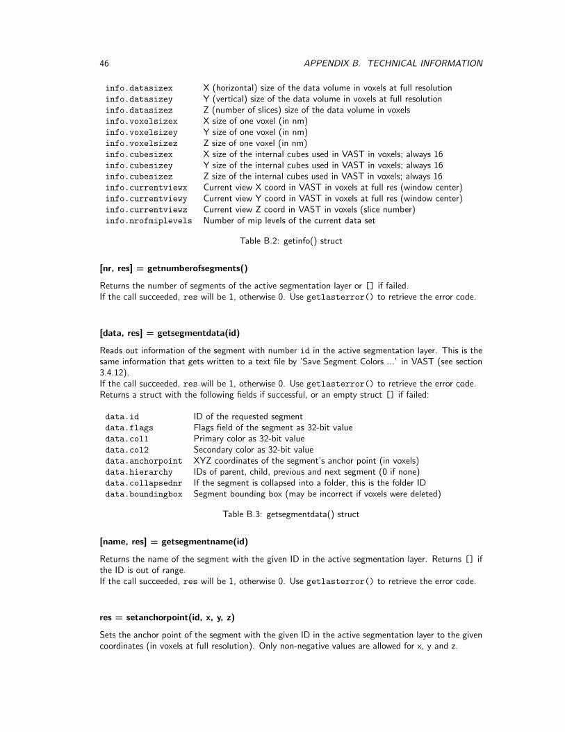
46 APPENDIX B. TECHNICAL INFORMATION
info.datasizex X (horizontal) size of the data volume in voxels at full resolutioninfo.datasizey Y (vertical) size of the data volume in voxels at full resolutioninfo.datasizez Z (number of slices) size of the data volume in voxelsinfo.voxelsizex X size of one voxel (in nm)info.voxelsizey Y size of one voxel (in nm)info.voxelsizez Z size of one voxel (in nm)info.cubesizex X size of the internal cubes used in VAST in voxels; always 16info.cubesizey Y size of the internal cubes used in VAST in voxels; always 16info.cubesizez Z size of the internal cubes used in VAST in voxels; always 16info.currentviewx Current view X coord in VAST in voxels at full res (window center)info.currentviewy Current view Y coord in VAST in voxels at full res (window center)info.currentviewz Current view Z coord in VAST in voxels (slice number)info.nrofmiplevels Number of mip levels of the current data set
Table B.2: getinfo() struct
[nr, res] = getnumberofsegments()
Returns the number of segments of the active segmentation layer or [] if failed.If the call succeeded, res will be 1, otherwise 0. Use getlasterror() to retrieve the error code.
[data, res] = getsegmentdata(id)
Reads out information of the segment with number id in the active segmentation layer. This is thesame information that gets written to a text file by ’Save Segment Colors ...’ in VAST (see section3.4.12).If the call succeeded, res will be 1, otherwise 0. Use getlasterror() to retrieve the error code.Returns a struct with the following fields if successful, or an empty struct [] if failed:
data.id ID of the requested segmentdata.flags Flags field of the segment as 32-bit valuedata.col1 Primary color as 32-bit valuedata.col2 Secondary color as 32-bit valuedata.anchorpoint XYZ coordinates of the segment’s anchor point (in voxels)data.hierarchy IDs of parent, child, previous and next segment (0 if none)data.collapsednr If the segment is collapsed into a folder, this is the folder IDdata.boundingbox Segment bounding box (may be incorrect if voxels were deleted)
Table B.3: getsegmentdata() struct
[name, res] = getsegmentname(id)
Returns the name of the segment with the given ID in the active segmentation layer. Returns [] ifthe ID is out of range.If the call succeeded, res will be 1, otherwise 0. Use getlasterror() to retrieve the error code.
res = setanchorpoint(id, x, y, z)
Sets the anchor point of the segment with the given ID in the active segmentation layer to the givencoordinates (in voxels at full resolution). Only non-negative values are allowed for x, y and z.

B.3. API FUNCTION REFERENCE 47
If the call succeeded, res will be 1, otherwise 0. Use getlasterror() to retrieve the error code.
res = setsegmentname(id, name)
Sets the name of the segment with the given ID in the active segmentation layer.If the call succeeded, res will be 1, otherwise 0. Use getlasterror() to retrieve the error code.
res = setsegmentcolor8(id, r1, g1, b1, p1, r2, g2, b2, p2)
Sets the primary and secondary colors (and pattern) of the segment with the given ID in the activesegmentation layer. Values for r1, g1, b1, r2, g2 and b2 have to be between 0 and 255. p1 definesthe pattern and has to be between 0 and 15. p2 is currently unused.If the call succeeded, res will be 1, otherwise 0. Use getlasterror() to retrieve the error code.
res = setsegmentcolor32(id, col1, col2)
Same as setsegmentcolor8, but the two colors for the segment are given as two 32-bit values.If the call succeeded, res will be 1, otherwise 0. Use getlasterror() to retrieve the error code.
[x, y, z, res] = getviewcoordinates()
Returns the current view coordinates in VAST in voxels at full resolution.If the call succeeded, res will be 1, otherwise 0. Use getlasterror() to retrieve the error code.
[zoom, res] = getviewzoom()
Returns the current zoom value in VAST.If the call succeeded, res will be 1, otherwise 0. Use getlasterror() to retrieve the error code.
res = setviewcoordinates(x, y, z)
Sets the current x, y, z coordinates (in voxels at full resolution) of the view (center of window) inVAST.If the call succeeded, res will be 1, otherwise 0. Use getlasterror() to retrieve the error code.
res = setviewzoom(zoom)
Sets the current zoom value. Zoom values are currently integer values and can be negative. Thehigher the value, the more magnified the view. A zoom value of 0 sets the pixel size of the fullresolution image to exactly the ’Target Resolution Smaller Than’ value specified in the VAST Pref-erences. A value of -8 zooms out by a factor 2 (and shows the next lower mip level texture).If the call succeeded, res will be 1, otherwise 0. Use getlasterror() to retrieve the error code.

48 APPENDIX B. TECHNICAL INFORMATION
[nroflayers, res] = getnroflayers()
Returns the number of layers currently loaded in VAST.If the call succeeded, res will be 1, otherwise 0. Use getlasterror() to retrieve the error code.
[linfo, res] = getlayerinfo(layernr)
Returns information about the layer with the given number. layernr can be a number between 0 andgetnroflayers-1. If the function succeeds, it will return a struct layerinfo with fields as describedbelow and res will be 1. If it fails it will return an empty struct and res will be 0. This returns thevalues which are also visible in the VAST ’Layers’ tool window.If the call succeeded, res will be 1, otherwise 0. Use getlasterror() to retrieve the error code.
linfo.type 0: EM layer (VSV); 1: Segmentation layer; 3: remote EM layerlinfo.editable 1 if the layer is editable, 0 elselinfo.visible 1 if the layer is visible, 0 else (’Visible’ checkbox)linfo.brightness ’Bright’ (brightness) or ’Pattern’ checkboxlinfo.contrast ’Contrast’ or ’Sel Alpha’ checkboxlinfo.opacitylevel Slider next to ’Visible’, which defines layer opacitylinfo.brightnesslevel Slider next to ’Bright’ or ’Pattern’linfo.contrastlevel Slider next to ’Contrast’ or ’Sel Alpha’linfo.blendmode The current blend mode (see below)linfo.blendoradd 0: alpha blending, 1: additive blendinglinfo.tintcolor Tint color as 32-bit RGBA value. Default: white (0xffffffff)linfo.name Name of the layerlinfo.redtargetcolor Red channel target color (RGBA). Default: red (0xff0000ff)linfo.greentargetcolor Green channel target color (RGBA). Default: green (0x00ff00ff)linfo.bluetargetcolor Blue channel target color (RGBA). Default: blue (0x0000ffff)
Table B.4: getlayerinfo() struct
Blend modes are: 0: no transparency (’Flat’), 1: the darker mean(r,g,b) the more transparent,2: the brighter mean(r,g,b) the more transparent, 3: the darker max(r,g,b), the more transparent,4: the brighter max(r,g,b), the more transparent.
[segdata, res] = getallsegmentdata()
This function is similar to data = getsegmentdata(id) above, but retrieves the data for all seg-ments in the active segmentation layer at once and returns a cell array of structs instead of a singlestruct.If the call succeeded, res will be 1, otherwise 0. Use getlasterror() to retrieve the error code.
[segdatamatrix, res] = getallsegmentdatamatrix()
Same as data = getallsegmentdata(id) above, but returns the data as a matrix with one rowper segment and one column per data value. The columns are the same as when exporting segmentmetadata to a file (see section 3.4.12), with the exception of the segment names.If the call succeeded, res will be 1, otherwise 0. Use getlasterror() to retrieve the error code.

B.3. API FUNCTION REFERENCE 49
[segname, res] = getallsegmentnames()
This function is similar to name = getsegmentname(id) above, but retrieves the names of all seg-ments in the active segmentation layer at once and returns them in a cell array. If the call succeeded,res will be 1, otherwise 0. Use getlasterror() to retrieve the error code.
res = setselectedsegmentnr(segmentnr)
Sets the selected segment in the active segmentation layer in VAST to the segment with the givenID number. If the call succeeded, res will be 1, otherwise 0. Use getlasterror() to retrieve theerror code.
[selectedsegmentnr, res] = getselectedsegmentnr()
Returns the ID number of the currently selected segment in the active segmentation layer, or -1 if anerror occurred. If the call succeeded, res will be 1, otherwise 0. Use getlasterror() to retrievethe error code.
res = setselectedlayernr(obj)
Sets the selected layer in VAST to the layer with the given ID number (counting from 0 as the firstlayer in the list). If the call succeeded, res will be 1, otherwise 0. Use getlasterror() to retrievethe error code.
[selectedlayernr, selectedemlayernr, selectedsegmentlayernr, res] = getselectedlayernr()
Returns the numbers of the currently selected layer, EM layer, and segment layer, or -1 if there is nosuch layer. The ’selected layer’ will always be either the ’selected EM layer’ or the ’selected segmentlayer’, whichever is actually highlighted in the ’Layers’ tool window in VAST. The other numberindicates the most recently selected layer of the other type.If the call succeeded, res will be 1, otherwise 0. Use getlasterror() to retrieve the error code.
[segimage, res] = getsegimageraw(miplevel, minx, maxx, miny, maxy, minz, maxz, flipflag)
Reads out the segmentation as a voxel image for a given mip level (resolution) and area, as defined byminimum and maximum values for the ranges in x, y and z. This function transmits the segmentationimage as raw data (a one-dimensional array of bytes); consider using getsegimageRLEdecoded()
below for a version with faster transmission. If flipflag is 1, X and Y axis will be swapped to makethe image appear the same as in VAST. If flipflag is unspecified or 0, segimage will appear withX and Y axis swapped.If the call succeeded, res will be 1, otherwise 0. Use getlasterror() to retrieve the error code.
minx, maxx, miny, maxy, minz and maxz are given in voxels at the resolution defined by miplevel.You can retrieve the size of the volume at full resolution (mip level 0) using the function getinfo().To compute the size of the volume in X and Y at a different mip level miplevel, use the followingcode:
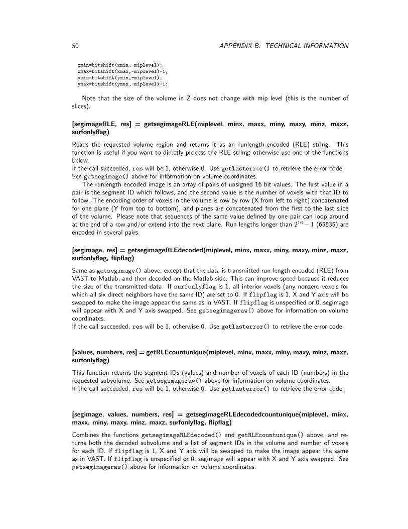
50 APPENDIX B. TECHNICAL INFORMATION
xmin=bitshift(xmin,-miplevel);
xmax=bitshift(xmax,-miplevel)-1;
ymin=bitshift(ymin,-miplevel);
ymax=bitshift(ymax,-miplevel)-1;
Note that the size of the volume in Z does not change with mip level (this is the number ofslices).
[segimageRLE, res] = getsegimageRLE(miplevel, minx, maxx, miny, maxy, minz, maxz,surfonlyflag)
Reads the requested volume region and returns it as an runlength-encoded (RLE) string. Thisfunction is useful if you want to directly process the RLE string; otherwise use one of the functionsbelow.If the call succeeded, res will be 1, otherwise 0. Use getlasterror() to retrieve the error code.See getsegimage() above for information on volume coordinates.
The runlength-encoded image is an array of pairs of unsigned 16 bit values. The first value in apair is the segment ID which follows, and the second value is the number of voxels with that ID tofollow. The encoding order of voxels in the volume is row by row (X from left to right) concatenatedfor one plane (Y from top to bottom), and planes are concatenated from the first to the last sliceof the volume. Please note that sequences of the same value defined by one pair can loop aroundat the end of a row and/or extend into the next plane. Run lengths longer than 216 − 1 (65535) areencoded in several pairs.
[segimage, res] = getsegimageRLEdecoded(miplevel, minx, maxx, miny, maxy, minz, maxz,surfonlyflag, flipflag)
Same as getsegimage() above, except that the data is transmitted run-length encoded (RLE) fromVAST to Matlab, and then decoded on the Matlab side. This can improve speed because it reducesthe size of the transmitted data. If surfonlyflag is 1, all interior voxels (any nonzero voxels forwhich all six direct neighbors have the same ID) are set to 0. If flipflag is 1, X and Y axis will beswapped to make the image appear the same as in VAST. If flipflag is unspecified or 0, segimagewill appear with X and Y axis swapped. See getsegimageraw() above for information on volumecoordinates.If the call succeeded, res will be 1, otherwise 0. Use getlasterror() to retrieve the error code.
[values, numbers, res] = getRLEcountunique(miplevel, minx, maxx, miny, maxy, minz, maxz,surfonlyflag)
This function returns the segment IDs (values) and number of voxels of each ID (numbers) in therequested subvolume. See getsegimageraw() above for information on volume coordinates.If the call succeeded, res will be 1, otherwise 0. Use getlasterror() to retrieve the error code.
[segimage, values, numbers, res] = getsegimageRLEdecodedcountunique(miplevel, minx,maxx, miny, maxy, minz, maxz, surfonlyflag, flipflag)
Combines the functions getsegimageRLEdecoded() and getRLEcountunique() above, and re-turns both the decoded subvolume and a list of segment IDs in the volume and number of voxelsfor each ID. If flipflag is 1, X and Y axis will be swapped to make the image appear the sameas in VAST. If flipflag is unspecified or 0, segimage will appear with X and Y axis swapped. Seegetsegimageraw() above for information on volume coordinates.
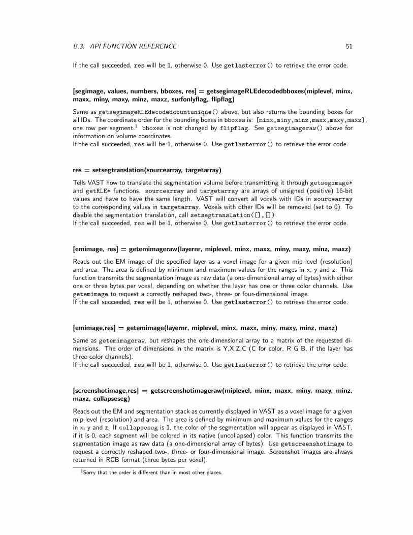
B.3. API FUNCTION REFERENCE 51
If the call succeeded, res will be 1, otherwise 0. Use getlasterror() to retrieve the error code.
[segimage, values, numbers, bboxes, res] = getsegimageRLEdecodedbboxes(miplevel, minx,maxx, miny, maxy, minz, maxz, surfonlyflag, flipflag)
Same as getsegimageRLEdecodedcountunique() above, but also returns the bounding boxes forall IDs. The coordinate order for the bounding boxes in bboxes is: [minx,miny,minz,maxx,maxy,maxz],one row per segment.1 bboxes is not changed by flipflag. See getsegimageraw() above forinformation on volume coordinates.If the call succeeded, res will be 1, otherwise 0. Use getlasterror() to retrieve the error code.
res = setsegtranslation(sourcearray, targetarray)
Tells VAST how to translate the segmentation volume before transmitting it through getsegimage*
and getRLE* functions. sourcearray and targetarray are arrays of unsigned (positive) 16-bitvalues and have to have the same length. VAST will convert all voxels with IDs in sourcearray
to the corresponding values in targetarray. Voxels with other IDs will be removed (set to 0). Todisable the segmentation translation, call setsegtranslation([],[]).If the call succeeded, res will be 1, otherwise 0. Use getlasterror() to retrieve the error code.
[emimage, res] = getemimageraw(layernr, miplevel, minx, maxx, miny, maxy, minz, maxz)
Reads out the EM image of the specified layer as a voxel image for a given mip level (resolution)and area. The area is defined by minimum and maximum values for the ranges in x, y and z. Thisfunction transmits the segmentation image as raw data (a one-dimensional array of bytes) with eitherone or three bytes per voxel, depending on whether the layer has one or three color channels. Usegetemimage to request a correctly reshaped two-, three- or four-dimensional image.If the call succeeded, res will be 1, otherwise 0. Use getlasterror() to retrieve the error code.
[emimage,res] = getemimage(layernr, miplevel, minx, maxx, miny, maxy, minz, maxz)
Same as getemimageraw, but reshapes the one-dimensional array to a matrix of the requested di-mensions. The order of dimensions in the matrix is Y,X,Z,C (C for color, R G B, if the layer hasthree color channels).If the call succeeded, res will be 1, otherwise 0. Use getlasterror() to retrieve the error code.
[screenshotimage,res] = getscreenshotimageraw(miplevel, minx, maxx, miny, maxy, minz,maxz, collapseseg)
Reads out the EM and segmentation stack as currently displayed in VAST as a voxel image for a givenmip level (resolution) and area. The area is defined by minimum and maximum values for the rangesin x, y and z. If collapseseg is 1, the color of the segmentation will appear as displayed in VAST,if it is 0, each segment will be colored in its native (uncollapsed) color. This function transmits thesegmentation image as raw data (a one-dimensional array of bytes). Use getscreenshotimage torequest a correctly reshaped two-, three- or four-dimensional image. Screenshot images are alwaysreturned in RGB format (three bytes per voxel).
1Sorry that the order is different than in most other places.
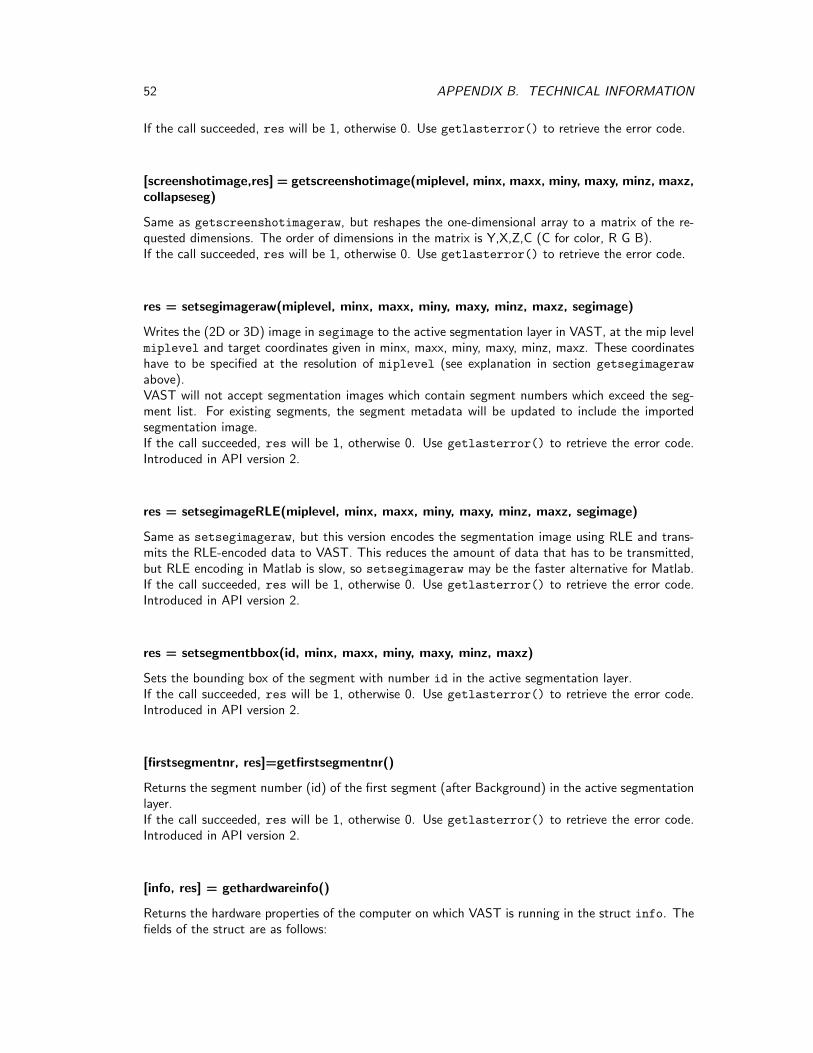
52 APPENDIX B. TECHNICAL INFORMATION
If the call succeeded, res will be 1, otherwise 0. Use getlasterror() to retrieve the error code.
[screenshotimage,res] = getscreenshotimage(miplevel, minx, maxx, miny, maxy, minz, maxz,collapseseg)
Same as getscreenshotimageraw, but reshapes the one-dimensional array to a matrix of the re-quested dimensions. The order of dimensions in the matrix is Y,X,Z,C (C for color, R G B).If the call succeeded, res will be 1, otherwise 0. Use getlasterror() to retrieve the error code.
res = setsegimageraw(miplevel, minx, maxx, miny, maxy, minz, maxz, segimage)
Writes the (2D or 3D) image in segimage to the active segmentation layer in VAST, at the mip levelmiplevel and target coordinates given in minx, maxx, miny, maxy, minz, maxz. These coordinateshave to be specified at the resolution of miplevel (see explanation in section getsegimageraw
above).VAST will not accept segmentation images which contain segment numbers which exceed the seg-ment list. For existing segments, the segment metadata will be updated to include the importedsegmentation image.If the call succeeded, res will be 1, otherwise 0. Use getlasterror() to retrieve the error code.Introduced in API version 2.
res = setsegimageRLE(miplevel, minx, maxx, miny, maxy, minz, maxz, segimage)
Same as setsegimageraw, but this version encodes the segmentation image using RLE and trans-mits the RLE-encoded data to VAST. This reduces the amount of data that has to be transmitted,but RLE encoding in Matlab is slow, so setsegimageraw may be the faster alternative for Matlab.If the call succeeded, res will be 1, otherwise 0. Use getlasterror() to retrieve the error code.Introduced in API version 2.
res = setsegmentbbox(id, minx, maxx, miny, maxy, minz, maxz)
Sets the bounding box of the segment with number id in the active segmentation layer.If the call succeeded, res will be 1, otherwise 0. Use getlasterror() to retrieve the error code.Introduced in API version 2.
[firstsegmentnr, res]=getfirstsegmentnr()
Returns the segment number (id) of the first segment (after Background) in the active segmentationlayer.If the call succeeded, res will be 1, otherwise 0. Use getlasterror() to retrieve the error code.Introduced in API version 2.
[info, res] = gethardwareinfo()
Returns the hardware properties of the computer on which VAST is running in the struct info. Thefields of the struct are as follows:

B.3. API FUNCTION REFERENCE 53
info.computername text Name of the computerinfo.processorname text Name of the processorinfo.processorspeed_ghz double Clock speed of the processor in GHzinfo.nrofprocessorcores integer Number of processor coresinfo.tickspeedmhz double Tick speed of the VAST computer in MHzinfo.mmxssecapabilities text Text describing the processor capabilitiesinfo.totalmemorygb double Memory installed, in GBinfo.freememorygb double Free memory, in GBinfo.graphicscardname text Graphics card nameinfo.graphicsdedicatedvideomemgb double Dedicated video memory in GBinfo.graphicsdedicatedsysmemgb double System memory dedicated for graphics, in GBinfo.graphicssharedsysmemgb double System memory shared for graphics, in GBinfo.graphicsrasterizerused text ’Undefined’, ’Hardware’, ’Warp’ or ’Reference’
Table B.5: gethardwareinfo() struct
If the call succeeded, res will be 1, otherwise 0. Use getlasterror() to retrieve the error code.Introduced in API version 2.

54 APPENDIX B. TECHNICAL INFORMATION
Bibliography
[1] Cardona A., Saalfeld S., Schindelin J., Arganda-Carreras I., Preibisch S., etal.: TrakEM2 Software for Neural Circuit Reconstruction, PLoS ONE, 7(6):e38011, (2012),doi:10.1371/journal.pone.0038011.
[2] Saalfeld, S., Fetter, R., Cardona, A., and Tomancak, P.: Elastic volume recon-struction from series of ultra-thin microscopy sections, Nature Methods, 9(7), (2012), 717-720.
[3] Srubek Tomassy, G., Berger, D., Chen, H., Kasthuri, N., Hayworth, K., Ver-celli, A., Seung, S., Lichtman, J., and Arlotta, P.: Distinct Profiles of MyelinDistribution Along Single Axons of Pyramidal Neurons in the Neocortex, Science, 344(6181),(2014) 319-324, doi:10.1126/science.1249766.
[4] Kasthuri, N., Hayworth, K., Berger, D., Schalek, R., Conchello, J., Knowles-Barley, S., Lee, D., Vazquez-Reina, A., Kaynig, V., Jones, T., Roberts, M.,Morgan, J., Tapia, J., Seung, H.S., Gray Roncal, W., Vogelstein, J., Burns,R., Sussman, D., Priebe, C., Pfister, H., and Lichtman J.: Saturated ReconstructionOf A Volume Of Neocortex, Cell, 162(3), (2015) 648-661.
[5] Morgan, J., Berger, D., and Lichtman J.: The Fuzzy Logic of Network Connectivityin Mouse Visual Thalamus, Cell, 165, (2016) 192-206.
[6] Quadrato, G., Nguyen, T., Macosko, E., Sherwood, J., Yang, S., Berger, D.,Maria, N., Scholvin, J., Goldman, M., Kinney, J., Boyden, E., Lichtman, J.,Williams, Z., McCarroll, S., and Arlotta, P.: Cell diversity and network dynamics inphotosensitive human brain organoids, Nature, 545, (2017), 48-53, doi:10.1038/nature22047.
55

56 BIBLIOGRAPHY