vassiliki demakis · barcelona pavilion 4 weeks the objective of this project was to recreate...
TRANSCRIPT

VASSILIKI DEMAKIS

Table of Contents
Arch 1121: Architectural Design CommunicationProfessor Karen Pearson
Still LifeTexture CollageColor TheoryContour DrawingBarcelona PavilionPerspective Journey
Arch 1100: Introduction to ArchitectureProfessor Karen Pearson
Thorncrown Chapel
Arch 1131: Introduction to Architectural DesignProfessor Jane Ostergaard
Assemblage, Hierarchy, & FormCommunity Gathering SpaceSpatial Sequence
Arch 2201: Architectural Design IProfessor Mark Pearson
Inspirations CollageCenter for Great Lakes Ecology
Arch 2202: Architectural Design IlProfessor Mark Pearson
Spatial AgencyUrban Infill
Arch 2220: Architectural ModelingProfessor Mark Pearson
Tugendhat Chair & Wine GlassEames Chair Farnsworth House
Arch 2302: Architectural Design BuildProfessor Mark Pearson
Prairie Meeting Point & Community Farm Gathering Space
Arch 2102: Detailing & Construction DocumentsProfessor Ted Kulinski
Office/Warehouse Construction Drawings
Arch 1101: Drawing lProfessor David Linneweh
CompositionsTea TimeFlowersIn the MomentFolding PaperPeaks and ValleysInterior PerspectiveChicago
Arch 1101: Basic Architectural DraftingProfessor Amy Gassen
Residential Drawings L I B
E R T
Y
S T R
E E T
CONC
RETE
SIDE
WALK
CONC
RETE
SIDE
WALK
456.33'
STORM INLET
SAN. MANHOLE
10' U
TILITY
EASE
MENT
STORM INLET
STORM MANHOLE
STORM INLET
SAN. MANHOLE
STORM MANHOLE
R27'
R16'
R27'
R3'
4'-0"CONCRETEINCLINE FORLOADINGDOCKS
55'
ONE STORY PROPOSED BUILDING
R27'
R12'
27'
R12'
R24'-6
"
R7'-6"
R40'
R5'
R1'-6"
R7'-6"
302.
55'
TO BE REMOVED - TYP.
9'9'
5'
127'-11"151'-6"
125'
106'
-6"
SITE PLANSCALE: 1/20" = 1'- 0"N
A-1

PLAN OBLIQUE
Still Life4 Weeks
The objective of this project was to model various shapes and create a composition with them. Various types of drawings were to be included as well as a case to contain the shapes.
TONES WITH INK WHITE TONES WITH PENCIL
CASE
PLAN
FRONT ELEVATION
LEFT ELEVATION
SECTION

Texture Collage1 Week
The objective of this project was to create a composition utilizing mutliple materials and to recreate the image using pencil tones.

Contour Drawing1 Week
The objective of this project was to draw a shoe and its section.
Color Theory1 Week
The objective of this project was to create a monochromatic composition using paint chips.

Barcelona Pavilion4 Weeks
The objective of this project was to recreate Ludwig Mies Van Der Rohe’s Barcelona Pavilion through various drawings and diagrams to learn about all aspects of the building.
STRUCTURE LINES
SOLIDS
PERSPECTIVE
DIAGRAMS SHADED PLAN OBLIQUE WITH MATERIALS
STRUCTURECIRCULATION
VOIDSLINES OF SIGHT

Perspective Journey3 Weeks
The objective of this project was to describe a journey through an imaginary environment by creating vignettes in perspective. The space was divided into three sections, each one uniquely different in design. A simplistic tunnel design led to a playful, geometric design that was on opposite ends from a linear, enclosed section.

Thorncrown Chapel2 Weeks
The objective of this project was to research and model Thorncrown Chapel by E. Fay Jones.

Residential Drawings12 Weeks

COLLAGE ADDITIONAL LINES SHADOWS
Assemblage, Hierarchy, & Form3 Weeks
The objective was to create an asymmetrical and symmetrical design utlizing a set of geometric constraints. A three-dimensional model was created to explore hierarchy and develop shadows from these forms.
The symmetrical design was a balanced composition of angles and curves. Curves created at all four corners are balanced with angular elements in between. The asymmetrical design mainly used curves which allows the eye to travel around the whole composition. Larger circular elements are combined with smaller ones and are repeated throughout the design.

PLAN OBLIQUE
PARTI
Community Gathering Space3 Weeks
The objective of this project was to design a space to attract people throughout campus to gather. The design had to incorporate required architectural elements that were simple in material, but could be complex depending on usage.
The solution was to create a high-energy and playful space using circular and diagonal elements. Angular walls and circular holes in the ground create an intriguing path that leads to the main gathering space, allowing people to interact with the space as well as people who visit.
CIRCULATION
GEOMETRY
SECTION
PLAN

Spatial Sequence2 Weeks
The objective of this project was to design an outdoor space for Fall, Summer, and Spring. The spaces had to have an overall theme and had to provide seating as well as landscape throughout the specified areas.
The main concept for this project was to have people experience the worst aspects of the seasons. For Summer, the space was open to the west, where the direction of sunlight is the harshest. Seating was also only located in between walls that would bounce the heat off each other. For Fall, wind can be strong, and it generally travels from the north, so a wind funnel was created with walls to take in the wind and funnel it through several pathways. Seating was also located in the areas where the wind is coming from. For the Spring space, rain is a prominent type of weather, so the space is located in a valley where water can accumulate.
The positioning of the walls and the angled positioning of the wood pieces create an organized chaos that visually interacts with the actual chaos of being in the space and experiencing the worst aspects of the seasons.

Inspirations Collage3 Weeks
The objective of this project was to take photographs and create sketches of elements and principles of architecture in Chicago. Using these images, text, a beautiful material, and a found object, a three-dimensional model was to be built from these inspirations.
The solution to this problem was to use Alexander Calder’s Flamingo surrounded by Mies Van Der Rohe buildings as the main focal point. These two pieces of architecture separately read as two different elements but when viewed together create a sense of visual balance. In order to capture this feeling, images were wrapped around boxes connected with chicken wire, wood sticks, and sheet metal, representing the grid-like structure of Chicago. A red curve wove throughout the linear elements to signify the moments of organized chaos, showing that there is a balance between structure and dynamism.
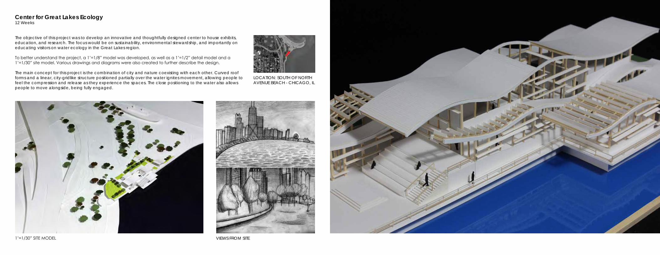
Center for Great Lakes Ecology12 Weeks
The objective of this project was to develop an innovative and thoughtfully designed center to house exhibits, education, and research. The focus would be on sustainability, environmental stewardship, and importantly on educating visitors on water ecology in the Great Lakes region.
To better understand the project, a 1’=1/8” model was developed, as well as a 1’=1/2” detail model and a 1’=1/30” site model. Various drawings and diagrams were also created to further describe the design.
The main concept for this project is the combination of city and nature coexisting with each other. Curved roof forms and a linear, city-gridlike structure positioned partially over the water ignites movement, allowing people to feel the compression and release as they experience the spaces. The close positioning to the water also allows people to move alongside, being fully engaged.
LOCATION: SOUTH OF NORTH AVENUE BEACH - CHICAGO, IL
1’=1/30” SITE MODEL VIEWS FROM SITE

EXHIBIT5'-0"
EXHIBIT2'-6"
0' 10' 20' 30' 40'SECTION A
OUTDOORCLASSROOM7'-6"
COURTYARD2'-6"
0' 10' 20' 30' 40'SECTION B
OUTDOORCLASSROOM
7'-6"
CAFE SEATING0'-0"
EXHIBIT5'-0"
EXHIBIT2'-6"
0' 10' 20' 30' 40'SECTION A
OUTDOORCLASSROOM7'-6"
COURTYARD2'-6"
0' 10' 20' 30' 40'SECTION B
OUTDOORCLASSROOM
7'-6"
CAFE SEATING0'-0"
SECTION A SECTION B
PLAN
INITIAL SCHEME
SITE PLAN
PARTI AND CIRCULATION
STRUCTURE
CONCEPT SKETCHES
STUDY MODELS

DETAIL MODEL
0’ 5’ 10’
C - LAB SECTION DETAIL


Spatial Agency3 Weeks
In a group of four, the objective of this project was to find an underutilized space at the College of DuPage campus and to propose architectural solutions to activate the space. Solutions had to be designed specifically to the space whether interior or exterior.
Our group chose the stairwells in the main building where the stairs lead down to a space about 14’ x 14’. Two different solutions were proposed for the stairwell. The first was to have a large seating area that could be used for club meetings and watching films. Acoustical panels that lead up the stairs are both used for a rhythmic design and for sound control. The second proposal was to have the space below be an art gallery for students’ work. A large, transparent shelf that goes up also houses students’ work and makes it appear as if the work is floating.
Overall, the main idea was to propose several options for the stairwell because the main building at COD has many of them and having each one be unique would allow students to be able to locate where they are in the building and be able to find use in a very small space.

Urban Infill12 Weeks
The objective of this project was to design a gallery, studio, and artist’s residence in the River North Gallery District in Chicago. Three pieces of artwork were chosen, and a gallery space had to be designed for each of them plus an installation gallery for temporary exhibits for the artist in residence. The first piece of artwork chosen was a sculpture by Donald Judd called “Untitled.” A large space was designed for the artwork and was hidden from the outside. It is located next to the train so passengers may catch a glimpse of the artwork, but would have to come to see what the people inside the gallery are looking at. The second piece was a cultural artifact of a Burden Basket made by the Pomos, a Native American tribe located in California. The gallery space for this piece was hidden in the back and had a low ceiling to create an intimate space and is small enough so viewers can be up close and experience the small details of the work. The final piece was a painting called “Interchanged” by Willem de Kooning and this piece is in an area with controlled lighting to preserve it and is the first piece people traveling up to the second floor see.
The main concept for the design of the building was plate tectonics. Floor plates were manipulated to act as shifting plates that were lifted up and down to create sublevels within each main level. Ramps and steps leading to each of these spaces created access to terraces on varied levels and overall, created movement. The outdoor terraces gave views to people on other levels and also unified them by providing all of them views to the city. The open atrium in the upper floors created lines of sight to other galleries on other levels and allowed viewers to witness the movement of floor plates as people used the space.
The design for the facade became a series of angled sunshades due to the uneven matching of the floor plates. The large, vertical sunshades give ample shade in one direction, but create a visual hierarchy in comparison to the smaller, horizontal sunshades throughout the exterior. The horizontal shades protect the interior more often throughout the day, but visually contrast with the vertical shades, giving a delicate appearance.
LINES OF SIGHT
NOISE
CIRCULATION
TYPES OF SPACES (TYPICALLY COMMERCIAL ON BOTTOM AND HOUSING ABOVE)
SCULPTURE PAINTINGCULTURAL ARTIFACTUNTITLED DONALD JUDD1968STAINLESS STEEL AND AMBER ACRYLIC
INTERCHANGED WILLEM DE KOONING1955OIL ON CANVAS
BURDEN BASKETPOMONORTHERN CALIFORNIA, US1870/80PLANT FIBERS
GALLERIESSCHOOLSPARK SPACESEATING RETAIL/OFFICEPARKINGUNKNOWN/VACANT
ANNUAL-YEARSEMI-YEAR (WINTER VIEWS)
AUTOMOBILESTRAINSPEDESTRIANSDIVVY BIKE STATIONBUS STOPLOCATION: CHICAGO AVENUE
AND FRANKLIN STREET SITE ANALYSIS ARTWORK ANALYSIS

RESIDENCE
CAFE/STUDIO
GALLERIES
INSTALLATION
ORGANIZATION
MOVEMENT OF FLOOR PLATES - PLATE TECTONICS
OPENING OF TERRACES CIRCULATING THE BUILDING
GIVING VIEWS AND INTERACTIONS TO OTHER LEVELS THROUGHOUT THE BUILDING AND CITY
CHICAGO AVENUE
FRA
NKL
IN S
TREE
T
LEVEL 1
LEVEL 2 LEVEL 3 LEVEL 4
D-DETAIL SECTION
OPEN ATRIUM TO ALLOW SUNLIGHT IN AND GIVE VIEWS TO DIFFERENT LEVELS
CIRCULATION
SECTION A SECTION B SECTION C
PROCESS MODELS - 1/32”=1’ and 1/4”=1’
CONCEPT SKETCHES


Tugendhat Chair and Wine Glass2 Weeks
The objective of this assignment was to recreate Mies Van der Rohe’s Tugendhat Chair and a wine glass. The goal was also to test out different materials, using the ART Renderer in 3DS Max.
Eames Chair1 Week
The objective of this assignment was to recreate a pre-designed chair using Rhino and then exporting it into 3DS Max to add material and render. The chair was of a design inspired by Ray and Charles Eames.

Farnsworth House4 Weeks
The objective of this project was to recreate Mies Van der Rohe’s Farnsworth House in Plano, Illinois. This project used programs such as AutoCAD, 3DS Max, and Google Sketchup, and emphasized the usage of the ART Renderer in 3DS and the VRAY Renderer in Sketchup to further develop rendering skills.

Compositions3 Weeks
Pencil
16” x 20”

Tea Time2 Weeks
Pencil
16” x 20”

In the Moment2 Weeks
Pencil
12” x 16”
Flowers1 Day
Ink
8.5” x 11”

Folding Paper1 Week
Charcoal 14” x 18”

Peaks and Valleys1 Week
Conte Crayons
14” x 18”
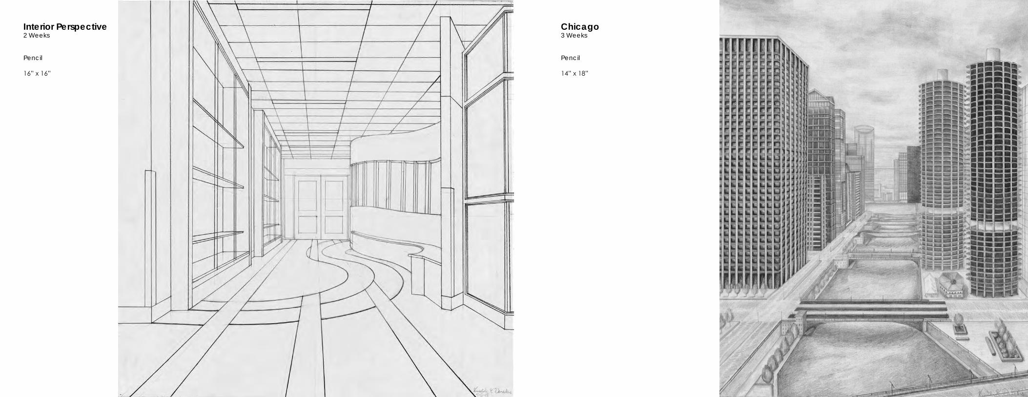
Chicago3 Weeks
Pencil
14” x 18”
Interior Perspective2 Weeks
Pencil
16” x 16”

Office/Warehouse Construction Drawings16 Weeks
211
A6
2
A
3
A6
4
A4
5
A56
A6
4
A4
A6
5
A5 DA
3 4
21 3 4
B
D
B
A
C
D
E
2
2
2
2
12
16
16
16
16
12
4
4
4
3
1516
16
3 3 3 3
1 2 3 4 5 6
AEEDA
EEEDA EEEDA
AAEEEEDA
AAE
EEEDA
AAEAEEDA
EEEDA
AAE
A B C D E
EEDAD
ADCEEEDA EAEDECEDE
ADC
A
D O O R S C H E D U L EROOM NAME REMARKS
DOOR FRAMEDOORMARK SIZE THICK. MAT'L. TYPE FINISH MAT'L. TYPE FINISH1A EBE A A A 1
1B EBE A A 1
12A EDECE D B A 2
13A CEECE D B A 2
16A CE 13 D D A 2
1A EEEEACE D A A 2
1A C D B A 2
1A EE
11A EE
112A C 134 D A
113A CE D A
114A CE D A
116A EECCA C 2
11A EEEEACE A
11A CEE D A
11A D A
12A D A
121A D A
122A D A
123A D B A A 5
124A
124B
124C
124D
124E
124 A
124 E
124 E124 3 C A 6 A
CECE
AEE
EAACE
EAACE
2EAED
2EAED
2EAED
A
A
A
A
A
AA
C A 6
C A 6
C A 6
C A 6
C A 6
C A 6
B A 5
B A 5
B A 5
B A 5B A 5
A A 6A
B A 5
B A 5
B A 5
A A
C
C
A
A
6
6
A
A
A
A
A
A
A
A
A
AA
A
A
A
A
A
A
A
A
A
A
3
3
3
3
3
3
3
3
3
3
3
3
3
3
3
3
3
3
3
3
3
3
3
3
33
13
134
134
134
134
134
134
134
134
134
134
134
134
134
134
134
134
134
134
134
134
134
134
134
134
134134
AEE
AEE
AEE
AEE
AEE
AEE
AEE
AEE
CE
CE
CE
R O O M F I N I S H S C H E D U L EROOM NO. ROOM NAME FLOOR BASE CEILING REMARKSCEILING
HEIGHTNORTH EAST SOUTH WESTMAT'L. FINISH MAT'L. FINISH MAT'L. FINISH MAT'L. FINISH MAT'L. FINISH MAT'L. FINISH MAT'L. FINISH
1 EBE C BB A AC11 ECEA AA12 EDECE AA13 CEECE A
14 AA
15 AA BB16 CE B B1 EEEEACE B1 C A
1 EE C B11 EE C B111 EEACE A112 C113 CE B114 CE
115 AA
116 EECCA CC B E11 EEEEACE
11 CEE B B11
12121
122
123 A B 124 CC B B E AE125 CC BB B E
CE
AEE
CE
C
C
C
A
A
AA
A
B
B B
A
A
A
C
C
C
C
C
C
C
C
C
C
C
C
C
C
C
C
C
AC
AC
AC
AC
AC
AC
AC
AC
AC
AC
AC
AC
AC
AC
AC
AC
AC
A
A
A
A
A
A
A
A
A
A
A
A
A
A
A
A
A
A
A
A
A
A
B
BB
BB
BB
BB
BB
BB
BB
BB
BB
BB
A
A
A
A
A
A
A
A
A
A
A
A
A
A
A
A
A
B
B
B
BB
B
B
A
A
A
A
A
A
A
A
AA
A
A
A
A
A
A
A
A
AA
A
A
A
A
A
A
AA
A
A
A
A
A
A
B
B
B
B
B
B
B
B
B
B
B
B
B
B
B
B
B
B
B
B
BA
B
B
B
B
B
BB
A
A
A
A
A
A
A
B
B
CE
CE
CE
ROOF PLANSCALE: 1/16" = 1'- 0"N
A-3
DOOR FRAME TYPESSCALE: 1/4" = 1'- 0"
DOOR TYPESSCALE: 1/4" = 1'- 0"
L I B
E R T
Y
S T R
E E T
CONC
RETE
SIDE
WALK
CONC
RETE
SIDE
WALK
456.33'
STORM INLET
SAN. MANHOLE
10' U
TILITY
EASE
MENT
STORM INLET
STORM MANHOLE
STORM INLET
SAN. MANHOLE
STORM MANHOLE
R27'
R16'
R27'
R3'
4'-0"CONCRETEINCLINE FORLOADINGDOCKS
55'
ONE STORY PROPOSED BUILDING
R27'
R12'
27'
R12'
R24'-6
"
R7'-6"
R40'
R5'
R1'-6"
R7'-6"
302.
55'
TO BE REMOVED - TYP.
9'9'
5'
127'-11"151'-6"
125'
106'
-6"
SITE PLANSCALE: 1/20" = 1'- 0"N
A-1
GENERAL OFFICE
100A100B
102A
103A
107A
108A
113A
106A124C
124D
124E
124F
124I
124G 124H
124B
124A116A
118A
114A
119A
117A
120A 121A 122A 123A
112A
109A 110A
VESTIBULE
RECEPTION / WAITING
PRESIDENT'SOFFICE
CONFERENCEROOM
ENTR
ANC
E
HALLWAY
LUNCH ROOM
WAREHOUSE
WOMEN MEN
HALLWAY
COPYROOM
OFFICEUTILITY
ELECT.
HALLWAY
OFF
ICE
SUPP
LIES
ENTR
ANC
E
OFFICE OFFICE OFFICE OFFICEV. P.' s
OFFICE
5'-0"TYP.
1'-6"
1'-0"
1'-6"
5'-0
"TY
P.
1'-8
"
20'-
0"
120
'-0
"
20'-
0"
20'-
0"
20'-
0"
1'-6"
18'-
6"
10"
1'-6"
1'-0
"
1'-6"
1'-6"
40'-
0"
40'-
0"
40'-
0"
120
'-0
"
10" THICK PRE-CAST CONCRETEPANELS 10'-0" WIDE TYP.
30'-0"
11"
27'-0" 30'-0" 30'-0"
151'-6"
NOTE:ALL INTERIOR PARTITIONS SHALLHAVE A NOMINAL THICKNESS OF5", PLUMBING WALLS SHALL BE1'-0" THICK.
102103
124
108
101
100
107
106
11310
4
112
110109
105
111
114
125
116
115
123122121120119
117
118
CLOSET
CLOSET
3
D
321
1
4
2
A
4
C
B
D
E
B
4
A-6
2
A-7
A
A-4
B
A-5
2
A-6
A
A-4
3
A-6
B
A-5
1
A-6
3
A-7
4
A-7
5
A-7
6
A-7
3'-11"
3'-0"
5'-1"
1
A-5
2
A-5
1
A-4
10"
10"
10'-4"
5"
9'-7"
5"
9'-7"
5"
9'-7"
5"
9'-7"
10"
1'-0
"
23'-5"10"
10"
10"
10"
5"
5"
4'-10"
5"
4'-7"
5"
4'-10" 15'-4"
5"
15'-4"
1'-0"
15'-
4"5"
5"
5'-6
"
5"
5'-6
"
5"
25'-
1"
5"
15'-
4"5"
7'-1
"5"
25'-
1"5"
11'-5
"
5"
4'-1
0"
5"
15'
-4"
1'-0
"
20
'-4"
18'-
2"
25'
-8"
15'-
4"
41'-1"
14'-2" 10'-0" 16'-5"
FIRST FLOOR PLANSCALE: 1/8" = 1'- 0"N
A-2
TOP OF STEEL H. P.
EL. = 20' - 10 12"
TOP FLOOR SLABEL. = 0' - 0"
TOP OF STEEL H. P.
EL. = 20' - 10 12"
TOP FLOOR SLABEL. = 0' - 0"
TOP OF STEELEL. = 13' - 4"
TOP FLOOR SLABEL. = 0' - 0"
TOP OF CMUEL. = 14' - 0"
HEIGHT OF CEILINGEL. = 9' - 0"
SECTIONSCALE: 1/2" = 1'- 0"4 SECTION
SCALE: 1/2" = 1'- 0" 1SECTIONSCALE: 1/2" = 1'- 0"3 SECTION
SCALE: 1/2" = 1'- 0"2 A-6
GENERAL OFFICE
VESTIBULE
RECEPTION / WAITING
PRESIDENT'SOFFICE
CONFERENCEROOM
ENTR
ANC
E
HALLWAY
LUNCH ROOM
WOMEN MEN
HALLWAY
COPYROOM
OFFICEUTILITY
ELECT.
HALLWAY
OFF
ICE
SUPP
LIES
EMPL
OYE
E EN
TRAN
CE
OFFICE OFFICE OFFICE OFFICE
V. P.' sOFFICE
CLOSET
CLOSET
WOMEN MEN
52" GRAB BAR (TYPICAL)
TOILET TISSUE DISPENSER SURFACEMOUNTED S.S. DOUBLE ROLL(TYPICAL)
URINAL SCREEN, 18" WIDEWALL HUNG W/ SUPPORTBRACKET
TOWEL DISPENSER S.S. SURFACEMOUNTED (4 TOTAL)
WASTE RECEPTACLE S.S. 36 GAL(4 TOTAL)
WASTE RECEPTACLE S.S. WITHTOP, 13 GAL (5 TOTAL)
TOILET PARTITIONS (TYPICAL)
SOAP DISPENSER, S.S., RECESSED,LIQUID (ONE @ EACH SINK)
MIRROR, S.S., 3/4" FRAME 66" X 24"
1'-10
"
3'-0
"
2'-5
"0
'-4"
2'-9
"9'
-0"
1'-10
"
3'-0
"
9'-0
"
2'-4
"0
'-4"
2'-9
"
OFFICE REFLECTIVE CEILING PLANSCALE: 1/4" = 1'- 0"N
LARGE SCALE RESTROOM PLANSCALE: 1/4" = 1'- 0"N
A-8
RESTROOM INTERIOR ELEVATIONSSCALE: 1/4" = 1'- 0"
2
F1
F5
F3
F2
F3
F3
F4
F4
STEP FOOTINGS
NOTE
STEP FOOTINGS
12
1
1
12
SPREAD FOOTING SCHEDULE
F1
F2
F3
F4
F5
5 5
4 43 3
3 3
1 3
1
C
E
F2
3 4
21 3
A
4
B
D
B
DF1
F1
F1
F5
F3
F5
F5
F3
F2
3
S3
1
S3
2
S3
4
S3
4
A
2
A
A
A4
B
A5
2
A
A
A4
3
A
B
A5
1
A
S3
5
S3
FOUNDATION PLANSCALE: 1/8" = 1'- 0"N
S-1
1
21 3
2
4
3 4
A
B
C
D
E
B
D
2
12
2
2
2
1
1
1
4
4
4
12
3 3 3 3
11
1
3
14 14
14 14
24
24
13
123
123
13
1
24 13 24
24
12
1222
1222
12
1
412 412
412 412
24 13 24
14 14
41
241
2
1 1
3
3
4
A
2
A
A
A4
B
A
2
A
A
A4
3
A
B
A
1
A
ROOF FRAMING PLANSCALE: 1/8" = 1'- 0"N
S-2
12" X 12" X 1"BASE PLATE
14" X 14"CONCRETE PIER
1/4" SETTING PLATE
3/4" GROUT
6" CONC. SLAB
8" GRANULAR BASE
12" X 12" X 1"BASE PLATE
1/4" SETTING PLATE
3/4" GROUT
X X X X X X X
5" CONC. SLAB6" GRANULAR BASE
TOP OF FOUNDATIONEL. = 0'-0"
TOP OF PIEREL. = -0'-10"
12" X 12" X 1"BASE PLATE
1/4" SETTING PLATE
3/4" GROUT
5" CONC. SLAB6" GRANULAR BASE
TOP OF FOUNDATIONEL. = 0'-0"
TOP OF PIEREL. = -0'-10"
4" X 8" X 1/2"EMBEDDED PLATE
3 1/2" X 5" X 1/2" LLV
6" CONC. SLAB
8" GRANULAR BASE
5" CONC. SLAB6" GRANULAR BASE
SECTIONSCALE: 3/4" = 1'- 0"3
SECTIONSCALE: 3/4" = 1'- 0"2 SECTION
SCALE: 3/4" = 1'- 0"1
DETAILSCALE: 3/4" = 1'- 0"5DETAIL
SCALE: 3/4" = 1'- 0"6
S-3
DETAILSCALE: 3/4" = 1'- 0"8 DETAIL
SCALE: 3/4" = 1'- 0"7
SECTIONSCALE: 3/4" = 1'- 0"4

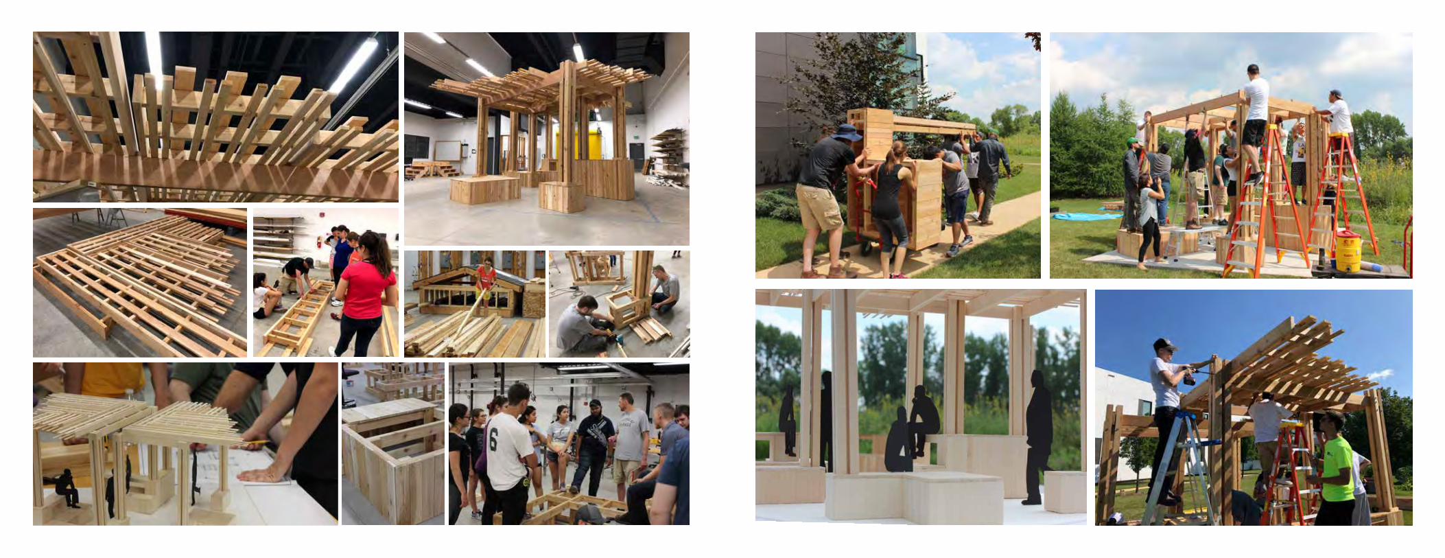
Design Build - Prairie Meeting Point & Community Farm Gathering Space8 Weeks
Over the course of 8 weeks, with a group of 15 students, the goal of this project was to design and build a pavilion that would serve as a meeting point for COD’s Prairie Tours as well as a resting place for the COD Community Garden and Fuel Pantry.
Students developed a range of ideas and were communicated both through physical and computer models. Regular presentations to the clients as well as the building code officials of Glen Ellyn gave a real-life experience to building a structure. After each critique, ideas were consolidated, and students formed larger groups, working together to achieve a design that was desirable to the client and was also able to be constructed in the last three weeks of the course.
The final design emphasized a large amount of seating and at multiple levels, allowing people to use the space in a variety of ways. The roof pattern evolved into a series of 1x4s and 1x2s that were positioned above and below 2x4s, making the roof have a delicate, wing-like appearance that provided ample amount of shade to the space.
Taking this course took students through the entire designing and building process that can be expected in the real world of design. Architecture students especially get accustomed to designing in the studio, creating digital and physical models of a structure, so being able to build what was designed allowed each student to gain and strengthen their skills in construction as well as designing for a real client.

STUDY 1: MULTIPLE SCHEMES STUDY 2: A-FRAME SCHEME
STUDY 3: COMBINING SCHEMES
FINAL DESIGN AND MODEL AT SCALE: 1 1/2”=1’
PROCESS