varispeed f7 user’s manual · varispeed f7 vector control frequency inverter user’s manual...
TRANSCRIPT

VARISPEED F7Vector Control Frequency Inverter
USER’S MANUAL
Manual No.YEG-TOE-S616-55.1-OY

Table of Content
Warnings ...................................................................................................... VIISafety Precautions and Instructions for Use ............................................... VIIIEMC Compatibility .......................................................................................... XLine Filters .................................................................................................... XIIRegistered Trademarks ................................................................................ XV1 Handling Inverters .................................................................. 1-1
Varispeed F7 Introduction ...........................................................................1-2Varispeed F7 Applications .............................................................................................1-2Varispeed F7 Models .....................................................................................................1-2
Confirmations upon Delivery .......................................................................1-4Checks ...........................................................................................................................1-4Nameplate Information ..................................................................................................1-4Component Names ........................................................................................................1-6
Exterior and Mounting Dimensions ..............................................................1-8Open Chassis Inverters (IP00) ......................................................................................1-8Enclosed Wall-mounted Inverters (NEMA1) ..................................................................1-9
Checking and Controlling the Installation Site ...........................................1-11Installation Site ............................................................................................................1-11Controlling the Ambient Temperature ..........................................................................1-11Protecting the Inverter from Foreign Matter .................................................................1-11
Installation Orientation and Space .............................................................1-12Removing and Attaching the Terminal Cover ............................................1-13
Removing the Terminal Cover .....................................................................................1-13Attaching the Terminal Cover ......................................................................................1-13
Removing/Attaching the Digital Operator and Front Cover .......................1-14Inverters of 18.5 kW or Less ........................................................................................1-14Inverters of 22 kW or More ..........................................................................................1-17
2 Wiring....................................................................................... 2-1
Connections to Peripheral Devices .............................................................2-2Connection Diagram ....................................................................................2-3
Circuit Descriptions ........................................................................................................2-4
Terminal Block Configuration ......................................................................2-5Wiring Main Circuit Terminals ......................................................................2-6
Applicable Wire Sizes and Closed-loop Connectors .....................................................2-6Main Circuit Terminal Functions ..................................................................................2-11Main Circuit Configurations ..........................................................................................2-12Standard Connection Diagrams ...................................................................................2-13Wiring the Main Circuits ...............................................................................................2-14
Wiring Control Circuit Terminals ................................................................2-20Wire Sizes ....................................................................................................................2-20Control Circuit Terminal Functions ..............................................................................2-22Control Circuit Terminal Connections ..........................................................................2-25Control Circuit Wiring Precautions ...............................................................................2-26
Wiring Check .............................................................................................2-27
I

II
Checks ........................................................................................................................ 2-27
Installing and Wiring Option Cards ............................................................ 2-28Option Card Models and Specifications ...................................................................... 2-28Installation ................................................................................................................... 2-28PG Speed Control Card Terminals and Specifications ............................................... 2-30PG-X2 .......................................................................................................................... 2-30Wiring .......................................................................................................................... 2-31Wiring Terminal Blocks ................................................................................................ 2-33
3 Digital Operator and Modes....................................................3-1
Digital Operator ........................................................................................... 3-2Digital Operator Display ................................................................................................ 3-2Digital Operator Keys .................................................................................................... 3-2
Modes ......................................................................................................... 3-4Inverter Modes .............................................................................................................. 3-4Switching Modes ........................................................................................................... 3-5Drive Mode .................................................................................................................... 3-6Quick Programming Mode ............................................................................................. 3-7Advanced Programming Mode ...................................................................................... 3-8Verify Mode ................................................................................................................. 3-10Autotuning Mode ......................................................................................................... 3-11
4 Trial Operation .........................................................................4-1
Trial Operation Procedure ........................................................................... 4-2Trial Operation ............................................................................................ 4-3
Application Confirmation ............................................................................................... 4-3Setting the Power Supply Voltage Jumper (400 V Class Inverters of 75 kW or Higher) 4-3Power ON ...................................................................................................................... 4-4Checking the Display Status ......................................................................................... 4-4Basic Settings ................................................................................................................ 4-5Settings for the Control Methods ................................................................................... 4-7Autotuning ..................................................................................................................... 4-8Application Settings ..................................................................................................... 4-12No-load Operation ....................................................................................................... 4-12Loaded Operation ........................................................................................................ 4-12Check and Recording Parameters .............................................................................. 4-13
Adjustment Suggestions ........................................................................... 4-14
5 User Parameters ......................................................................5-1
User Parameter Descriptions ...................................................................... 5-2Description of User Parameter Tables .......................................................................... 5-2
Digital Operation Display Functions and Levels .......................................... 5-3User Parameters Available in Quick Programming Mode ............................................. 5-4
User Parameter Tables ............................................................................... 5-7A: Setup Settings ........................................................................................................... 5-7Application Parameters: b ............................................................................................. 5-9Tuning Parameters: C ................................................................................................. 5-19Reference Parameters: d ............................................................................................ 5-25

Motor Parameters: E ....................................................................................................5-30Option Parameters: F ..................................................................................................5-35Terminal Function Parameters: H ................................................................................5-41Protection Function Parameters: L ..............................................................................5-50N: Special Adjustments ................................................................................................5-58Digital Operator Parameters: o ....................................................................................5-60U: Monitor Parameters .................................................................................................5-64Factory Settings that Change with the Control Method (A1-02) ..................................5-70Factory Settings that Change with the Inverter Capacity (o2-04) ................................5-72Parameter Initial Values that Change With the Setting of C6-01 .................................5-74
6 Parameter Settings by Function............................................ 6-1
Application and Overload Selections ...........................................................6-2Select the Overload to Suit the Application ...................................................................6-2
Frequency Reference ..................................................................................6-7Selecting the Frequency Reference Source ..................................................................6-7Using Multi-Step Speed Operation ..............................................................................6-10
Run Command Input Methods ...................................................................6-12Selecting the Run Command Source ..........................................................................6-12
Stopping Methods ......................................................................................6-14Selecting the Stopping Method when a Stop Command is Input .................................6-14Using the DC Injection Brake .......................................................................................6-17Using an Emergency Stop ...........................................................................................6-18
Acceleration and Deceleration Characteristics ..........................................6-19Setting Acceleration and Deceleration Times ..............................................................6-19Accelerating and Decelerating Heavy Loads (Dwell Function) ....................................6-22Preventing the Motor from Stalling During Acceleration (Stall Prevention During Acceleration Function) .....................................................................................6-22Preventing Overvoltage During Deceleration ..............................................................6-24
Adjusting Frequency References ..............................................................6-26Adjusting Analog Frequency References ....................................................................6-26Operation Avoiding Resonance (Jump Frequency Function) ......................................6-28
Speed Limit (Frequency Reference Limits) ...............................................6-30Limiting the Maximum Output Frequency ....................................................................6-30Limiting the Minimum Output Frequency .....................................................................6-30
Frequency Detection .................................................................................6-31Speed Agreement Function .........................................................................................6-31
Improving the Operation Performance ......................................................6-33Reducing the Motor Speed Fluctuation (Slip Compensation Function) .......................6-33Torque Compensation for Sufficient Torque at Start and Low-speed Operation .....................................................................................................................6-35Automatic Speed Regulator (ASR) ..............................................................................6-36Hunting-Prevention Function .......................................................................................6-41Stabilizing Speed (Automatic Frequency Regulator) ...................................................6-42
Machine Protection ....................................................................................6-43Limiting Motor Torque (Torque Limit Function) ............................................................6-43Preventing Motor Stalling During Operation ................................................................6-45Motor Torque Detection ...............................................................................................6-46Motor Overload Protection ...........................................................................................6-48
III
IV
Motor Overheating Protection Using PTC Thermistor Inputs ...................................... 6-50Limiting Motor Rotation Direction and Output Phase Rotation .................................... 6-51
Automatic Restart ...................................................................................... 6-52Restarting Automatically After Momentary Power Loss .............................................. 6-52Speed Search .............................................................................................................. 6-53Continuing Operation at Constant Speed when the Frequency Reference is Lost ..... 6-57Restarting Operation After Transient Error (Auto Restart Function) ........................... 6-58
Inverter Protection ..................................................................................... 6-59Overheating Protection for an Inverter-Mounted Braking Resistor .............................. 6-59Inverter Overheat Protection ....................................................................................... 6-60Input Open Phase Protection ...................................................................................... 6-60Output Open Phase Protection ................................................................................... 6-61Ground Fault Protection .............................................................................................. 6-61Cooling Fan Control .................................................................................................... 6-61Setting the Ambient Temperature ............................................................................... 6-62OL2 Characteristics at Low Speed .............................................................................. 6-63
Input Terminal Functions ........................................................................... 6-64Temporarily Switching Operation between Digital Operator and Control Circuit Terminals ............................................................................................. 6-64Blocking the Inverter Output (Baseblock Commands) ................................................ 6-64OH2 (Overheat) Alarm Signal Input ............................................................................ 6-65Multifunction Analog Input A2 Disable/Enable ............................................................ 6-65Drive Enable/Disable ................................................................................................... 6-66Stopping Acceleration and Deceleration (Acceleration/Deceleration Ramp Hold) ...... 6-66Raising and Lowering Frequency References Using Contact Signals (UP/DOWN) ... 6-67Adding/Subtracting a Fixed Speed to an Analog Reference (Trim Control) ................ 6-69Hold Analog Frequency Using User-set Timing .......................................................... 6-71Switching Operation Source to Communication Option Card ..................................... 6-72Jog Frequency with Direction Commands (FJOG/RJOG) ........................................... 6-72Stopping the Inverter on External Device Errors (External Error Function) ................. 6-73
Output Terminal Functions ........................................................................ 6-74Monitor Parameters ................................................................................... 6-77
Using the Analog Monitor Outputs .............................................................................. 6-77Using the Pulse Train Monitor Output ......................................................................... 6-78
Individual Functions .................................................................................. 6-80Using MEMOBUS Communications ............................................................................ 6-80Using the Timer Function ............................................................................................ 6-95Using PID Control ........................................................................................................ 6-96Energy-saving ........................................................................................................... 6-106Field Weakening ........................................................................................................ 6-107Field Forcing .............................................................................................................. 6-108Setting Motor 1 Parameters ...................................................................................... 6-108Setting the V/f Pattern 1 ............................................................................................ 6-110Setting Motor 2 Parameters ...................................................................................... 6-116Setting the V/f Pattern 2 ............................................................................................ 6-117Torque Control .......................................................................................................... 6-118Droop Control Function ............................................................................................. 6-124Zero-Servo Function .................................................................................................. 6-125Kinetic Energy Buffering ............................................................................................ 6-127High Slip Braking (HSB) ............................................................................................ 6-128
Digital Operator Functions ...................................................................... 6-130

Setting Digital Operator Functions .............................................................................6-130Copying Parameters ..................................................................................................6-132Prohibiting Overwriting of Parameters .......................................................................6-136Setting a Password ....................................................................................................6-136Displaying User-set Parameters Only ........................................................................6-137
Option Cards ...........................................................................................6-138Using PG Feedback Option Cards ............................................................................6-138Analog Reference Cards ...........................................................................................6-141Digital Reference Cards .............................................................................................6-141
7 Troubleshooting ..................................................................... 7-1
Protective and Diagnostic Functions ...........................................................7-2Fault Detection ...............................................................................................................7-2Alarm Detection .............................................................................................................7-9Operator Programming Errors .....................................................................................7-12 Auto-tuning Fault ........................................................................................................7-14Digital Operator Copy Function Faults .........................................................................7-15
Troubleshooting .........................................................................................7-17If A Parameter Cannot Be Set .....................................................................................7-17If the Motor Does Not Operate Properly ......................................................................7-18If the Direction of the Motor Rotation is Reversed .......................................................7-19If the Motor Stalls or Acceleration is Slow ...................................................................7-19If the Motor Operates at Higher Speed than the Frequency Reference ......................7-20If There is Low Speed Control Accuracy Above Base Speed in Open Loop Vector Control Mode .................................................................................7-20If Motor Deceleration is Slow .......................................................................................7-20If the Motor Overheats .................................................................................................7-21If Peripheral Devices Like PLCs or Others are Influenced by the Starting or Running Inverter ......................................................................................................7-21If the Earth Leakage Breaker Operates When the Inverter is Running .......................7-21If There is Mechanical Oscillation ................................................................................7-22If the Motor Rotates Even When Inverter Output is Stopped .......................................7-23If Output Frequency Does Not Rise to Frequency Reference .....................................7-23
8 Maintenance and Inspection.................................................. 8-1
Maintenance and Inspection ........................................................................8-2Periodic Inspection ........................................................................................................8-2Periodic Maintenance of Parts .......................................................................................8-3Cooling Fan Replacement .............................................................................................8-4Removing and Mounting the Terminal Card ..................................................................8-6
9 Specifications ......................................................................... 9-1
Standard Inverter Specifications ..................................................................9-2Specifications by Model .................................................................................................9-2Common Specifications .................................................................................................9-4
V

VI
10 Appendix ................................................................................10-1
Inverter Application Precautions ............................................................... 10-2Selection ...................................................................................................................... 10-2Installation ................................................................................................................... 10-3Settings ....................................................................................................................... 10-3Handling ...................................................................................................................... 10-4
Motor Application Precautions .................................................................. 10-5Using the Inverter for an Existing Standard Motor ...................................................... 10-5Using the Inverter for Special Motors .......................................................................... 10-5Power Transmission Mechanism (Speed Reducers, Belts and Chains) ..................... 10-6
User Constants ......................................................................................... 10-7

Warnings
CAUTION
Cables must not be connected or disconnected, nor signal tests carried out, while the power is switched on.
The Varispeed F7 DC bus capacitor remains charged even after the power has been switched off. To avoid an electric shock hazard, disconnect the frequency inverter from the mains before carrying out maintenance. Then wait for at least 5 minutes after all LEDs have gone out.Do not perform a withstand voltage test on any part of the inverter. It contains semiconductors, which are not designed for such high voltages.
Do not remove the digital operator while the mains supply is switched on. The printed circuit board must also not be touched while the inverter is connected to the power.
Never connect general LC/RC interference suppression filters, capacitors or overvoltage protection devices to the inverter input or output.
To avoid unnecessary overcurrent faults, etc. being displayed, the signaling contacts of any contac-tor or switch fitted between inverter and motor must be integrated into the inverter control logic (e.g. baseblock).
This is absolutely imperative!
This manual must be read thoroughly before connecting and operating the inverter. All safety pre-cautions and instructions for use must be followed.
The inverter must be operated with the appropriate line filters, following the installation instructions in this manual and with all covers closed and terminals covered.Only then will adequate protection be provided. Please do not connect or operate any equipment with visible damage or missing parts. The operating company is responsible for any injuries or equipment damage resulting from failure to heed the warnings in this manual.
VII

VIII
Safety Precautions and Instructions for Use
GeneralPlease read these safety precautions and instructions for use thoroughly before installing and operating thisinverter. Also read all of the warning signs on the inverter and ensure they are never damaged or removed.
Live and hot inverter components may be accessible during operation. Removal of housing components, thedigital operator or terminal covers runs the risk of serious injuries or damage in the event of incorrect installa-tion or operation. The fact that frequency inverters control rotating mechanical machine components can giverise to other dangers.
The instructions in this manual must be followed. Installation, operation and maintenance may only be carriedout by qualified personnel. For the purposes of the safety precautions, qualified personnel are defined as indi-viduals who are familiar with the installation, starting, operation and maintenance of frequency inverters andhave the proper qualifications for this work. Safe operation of these units is only possible if they are usedproperly for their intended purpose.
The DC bus capacitors can remain live for about 5 minutes after the inverter is disconnected from the power.It is therefore necessary to wait for this time before opening its covers. All of the main circuit terminals maystill carry dangerous voltages.
Children and other unauthorized persons must not be allowed access to these inverters.
Keep these Safety Precautions and Instructions for Use readily accessible and supply them to all persons withany form of access to the inverters.
Intended UseFrequency inverters are intended for installation in electrical systems or machinery.
Their installation in machinery and systems must conform to the following product standards of the Low Volt-age Directive:
EN 50178, 1997-10,Equipping of Power Systems with Electronic Devices
EN 60204-1, 1997-12Machine Safety and Equipping with Electrical Devices
Part 1: General Requirements (IEC 60204-1:1997)/
Please note: Includes Corrigendum of September 1998
EN 61010-1, A2, 1995Safety Requirements for Information Technology Equipment
(IEC 950, 1991 + A1, 1992 + A2, 1993 + A3, 1995 + A4, 1996, modified)
CE marking is carried out to EN 50178, using the line filters specified in this manual and following the appro-priate installation instructions.
Transportation and storageThe instructions for transportation, storage and proper handling must be followed in accordance with the tech-nical data.
InstallationInstall and cool the inverters as specified in the documentation. The cooling air must flow in the specifieddirection. The inverter may therefore only be operated in the specified position (e.g. upright). Maintain thespecified clearances. Protect the inverters against impermissible loads. Components must not be bent nor insu-lation clearances changed. To avoid damage being caused by static electricity, do not touch any electroniccomponents or contacts.
Electrical ConnectionCarry out any work on live equipment in compliance with the national safety and accident prevention regula-tions. Carry out electrical installation in compliance with the relevant regulations. In particular, follow theinstallation instructions ensuring electromagnetic compatibility (EMC), e.g. shielding, grounding, filterarrangement and laying of cables. This also applies to equipment with the CE mark. It is the responsibility ofthe manufacturer of the system or machine to ensure conformity with EMC limits.
Your supplier or OYMC representative must be contacted when using leakage current circuit breaker in con-junction with frequency inverters.
In certain systems it may be necessary to use additional monitoring and safety devices in compliance with therelevant safety and accident prevention regulations. The frequency inverter hardware must not be modified.
NotesThe VARISPEED F7 frequency inverters are certified to CE, UL, and c-UL.
IX

X
EMC Compatibility
IntroductionThis manual was compiled to help system manufacturers using YASKAWA frequency inverters to design andinstall electrical switch gear. It also describes the measures necessary to comply with the EMC Directive. Themanual's installation and wiring instructions must therefore be followed.
Our products are tested by authorized bodies using the standards listed below.
Product standard: EN 61800-3:1996EN 61800-3; A11:2000
Measures to Ensure Conformity of YASKAWA Frequency inverters to the EMC Direc-tive
YASKAWA frequency inverters do not necessarily have to be installed in a switch cabinet.
It is not possible to give detailed instructions for all of the possible types of installation. This manual thereforehas to be limited to general guidelines.
All electrical equipment produces radio and line-borne interference at various frequencies. The cables passthis on to the environment like an aerial.
Connecting an item of electrical equipment (e.g. drive) to a supply without a line filter can therefore allow HFor LF interference to get into the mains.
The basic countermeasures are isolation of the wiring of control and power components, proper grounding andshielding of cables.
A large contact area is necessary for low-impedance grounding of HF interference. The use of groundingstraps instead of cables is therefore definitely advisable.
Moreover, cable shields must be connected with purpose-made ground clips.
Laying CablesMeasures Against Line-Borne Interference:
Line filter and frequency inverter must be mounted on the same metal plate. Mount the two components asclose to each other as possible, with cables kept as short as possible.
Use a power cable with well-grounded shield. Use a shielded motor cable not exceeding 20 meters in length.Arrange all grounds so as to maximize the area of the end of the lead in contact with the ground terminal (e.g.metal plate).
Shielded Cable: • –Use a cable with braided shield.• –Ground the maximum possible area of the shield. It is advisable to ground the shield by connecting the
cable to the ground plate with metal clips (see following figure).
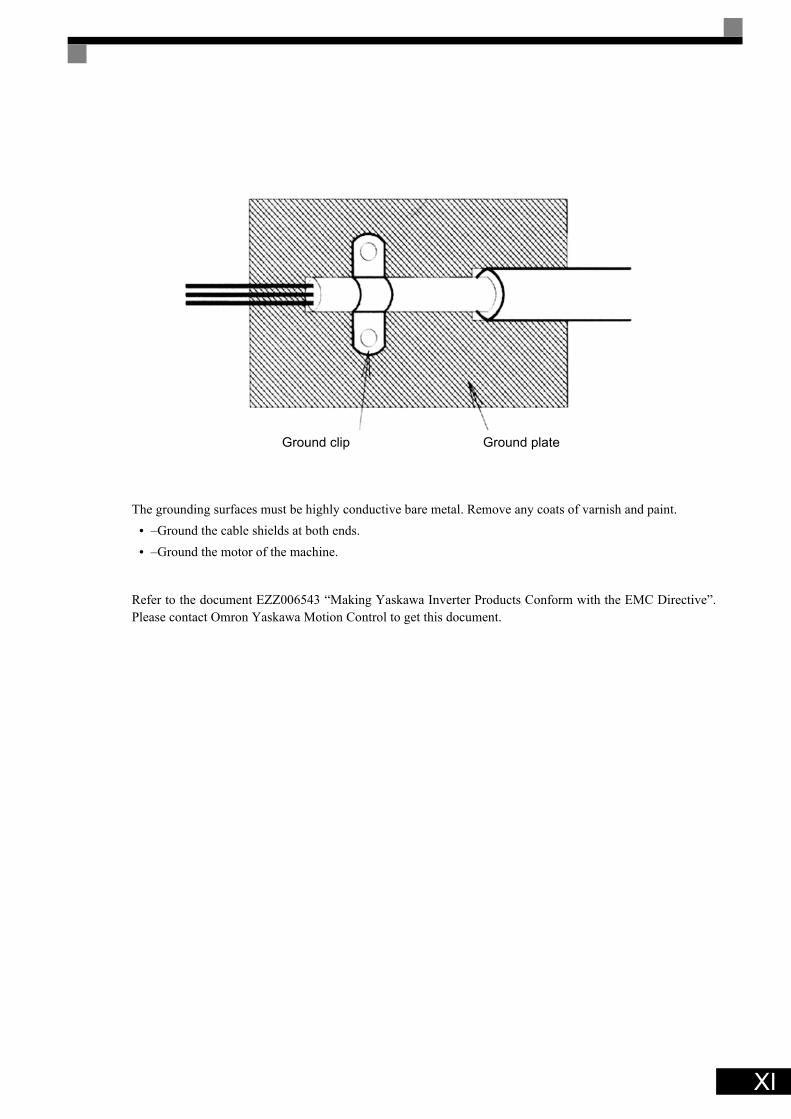
The grounding surfaces must be highly conductive bare metal. Remove any coats of varnish and paint.• –Ground the cable shields at both ends.• –Ground the motor of the machine.
Refer to the document EZZ006543 “Making Yaskawa Inverter Products Conform with the EMC Directive”.Please contact Omron Yaskawa Motion Control to get this document.
Ground clip Ground plate
XI
XII
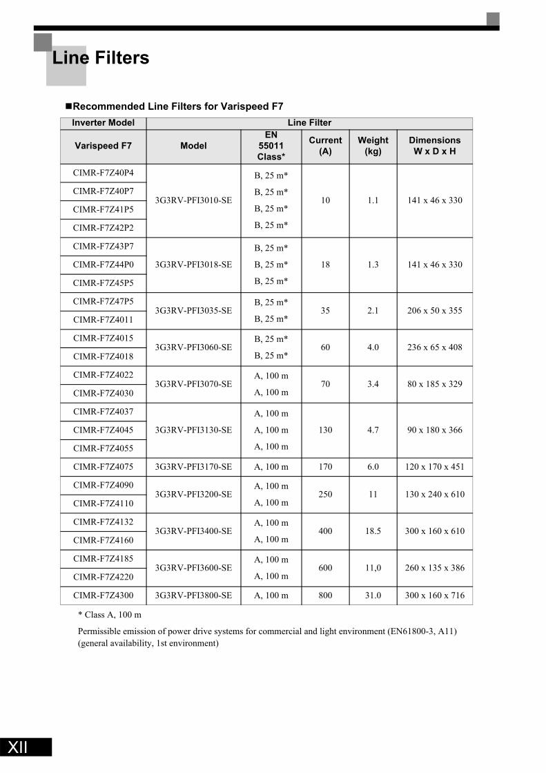
Line Filters
Recommended Line Filters for Varispeed F7
* Class A, 100 m
Permissible emission of power drive systems for commercial and light environment (EN61800-3, A11)(general availability, 1st environment)
Inverter Model Line Filter
Varispeed F7 ModelEN
55011 Class*
Current(A)
Weight(kg)
DimensionsW x D x H
CIMR-F7Z40P4
3G3RV-PFI3010-SE
B, 25 m*
B, 25 m*
B, 25 m*
B, 25 m*
10 1.1 141 x 46 x 330CIMR-F7Z40P7
CIMR-F7Z41P5
CIMR-F7Z42P2
CIMR-F7Z43P7
3G3RV-PFI3018-SE
B, 25 m*
B, 25 m*
B, 25 m*
18 1.3 141 x 46 x 330CIMR-F7Z44P0
CIMR-F7Z45P5
CIMR-F7Z47P53G3RV-PFI3035-SE
B, 25 m*
B, 25 m*35 2.1 206 x 50 x 355
CIMR-F7Z4011
CIMR-F7Z40153G3RV-PFI3060-SE
B, 25 m*
B, 25 m*60 4.0 236 x 65 x 408
CIMR-F7Z4018
CIMR-F7Z40223G3RV-PFI3070-SE
A, 100 m
A, 100 m70 3.4 80 x 185 x 329
CIMR-F7Z4030
CIMR-F7Z4037
3G3RV-PFI3130-SE
A, 100 m
A, 100 m
A, 100 m
130 4.7 90 x 180 x 366CIMR-F7Z4045
CIMR-F7Z4055
CIMR-F7Z4075 3G3RV-PFI3170-SE A, 100 m 170 6.0 120 x 170 x 451
CIMR-F7Z40903G3RV-PFI3200-SE
A, 100 m
A, 100 m250 11 130 x 240 x 610
CIMR-F7Z4110
CIMR-F7Z41323G3RV-PFI3400-SE
A, 100 m
A, 100 m400 18.5 300 x 160 x 610
CIMR-F7Z4160
CIMR-F7Z41853G3RV-PFI3600-SE
A, 100 m
A, 100 m600 11,0 260 x 135 x 386
CIMR-F7Z4220
CIMR-F7Z4300 3G3RV-PFI3800-SE A, 100 m 800 31.0 300 x 160 x 716

* Class A, 100 m
Inverter Model Line Filters
Varispeed F7 TypeEN
55011 Class
Current(A)
Weight(kg)
DimensionsW x D x H
CIMR-F7Z20P4
3G3RV-PFI3010-SE
B, 25 m*
B, 25 m*
B, 25 m*
10 1.1 141 x 45 x 330CIMR-F7Z20P7
CIMR-F7Z21P5
CIMR-F7Z22P2 3G3RV-PFI3018-SE B, 25 m* 18 1.3 141 x 46 x 330
CIMR-F7Z23P73G3RV-PFI2035-SE
B, 25 m*
B, 25 m*35 1.4 141 x 46 x 330
CIMR-F7Z25P5
CIMR-F7Z27P53G3RV-PFI2060-SE
B, 25 m*
B, 25 m*60 3 206 x 60 x 355
CIMR-F7Z2011
CIMR-F7Z20153G3RV-PFI2100-SE
B, 25 m*
B, 25 m*100 4.9 236 x 80 x 408
CIMR-F7Z2018
CIMR-F7Z20223G3RV-PFI2130-SE
A, 100 m
A, 100 m130 4.3 90 x 180 x 366
CIMR-F7Z2030
CIMR-F7Z2037 3G3RV-PFI2160-SE A, 100 m 160 6.0 120 x 170 x 451
CIMR-F7Z20453G3RV-PFI2200-SE
A, 100 m
A, 100 m200 11.0 130 x 240 x 610
CIMR-F7Z2055
CIMR-F7Z20753G3RV-PFI3400-SE
A, 100 m
A, 100 m400 18.5 300 x 160 x 564
CIMR-F7Z2090
CIMR-F7Z2110 3G3RV-PFI3600-SE A, 100 m 600 11.0 260 x 135 x 386
XIII

XIV
Installation of Inverters and EMC filters
L1 L3L2
3~M
UPE
L1L2
L3VW
PE
FilterInverter
Line
Load
Ground Bonds( remove any paint )
Cable Lengthas short as possible
Ground Bonds( remove any paint )
Metal Plate
Motor cablescreened
PE
PE

Registered Trademarks
The following registered trademarks are used in this manual.• DeviceNet is a registered trademark of the ODVA (Open DeviceNet Vendors Association, Inc.).• InterBus is a registered trademark of Phoenix Contact Co. • Profibus is a registered trademark of Siemens AG.
XV

XVI

1Handling Inverters
This chapter describes the checks required upon receiving or installing an Inverter.
Varispeed F7 Introduction......................................................1-2 Confirmations upon Delivery..................................................1-4 Exterior and Mounting Dimensions ........................................1-8 Checking and Controlling the Installation Site .....................1-11 Installation Orientation and Space .......................................1-12 Removing and Attaching the Terminal Cover ......................1-13 Removing/Attaching the Digital Operator and Front Cover..1-14

1-2
1
Varispeed F7 Introduction
Varispeed F7 Applications
The Varispeed F7 is ideal for the following applications.• Fan, blower, and pump applications• Conveyors, pushers, metal tooling machines, etc.
Settings must be adjusted to the application for optimum operation. Refer to Chapter 4 Trial Operation
Varispeed F7 Models
The Varispeed F7 Series includes Inverters in two voltage classes: 200 V and 400 V. The maximum motor capacitiesvary from 0.55 to 300 kW (42 models).
Table 1.1 Varispeed F7 Models
Voltage Class
Maxi-mum Motor
Capacity kW
Varispeed F7Specifications
(Always specify through the protective structure when ordering.)
Output Capacity
kVABasic Model Number
Open Chassis(IEC IP00)
CIMR-F7Z
Enclosed Wall-mounted(IEC IP20, NEMA 1)
CIMR-F7Z
200 V class
0.55 1.2 CIMR-F7Z20P4
Remove the top and bottom covers from the Enclosed
Wall-mounted model.
20P41
0.75 1.6 CIMR-F7Z20P7 20P71
1.5 2.7 CIMR-F7Z21P5 21P51
2.2 3.7 CIMR-F7Z22P2 22P21
3.7 5.7 CIMR-F7Z23P7 23P71
5.5 8.8 CIMR-F7Z25P5 25P51
7.5 12 CIMR-F7Z27P5 27P51
11 17 CIMR-F7Z2011 20111
15 22 CIMR-F7Z2015 20151
18.5 27 CIMR-F7Z2018 20181
22 32 CIMR-F7Z2022 20220 20221
30 44 CIMR-F7Z2030 20300 20301
37 55 CIMR-F7Z2037 20370 20371
45 69 CIMR-F7Z2045 20450 20451
55 82 CIMR-F7Z2055 20550 20551
75 110 CIMR-F7Z2075 20750 20751
90 130 CIMR-F7Z2090 20900 –
110 160 CIMR-F7Z2110 21100 –

1
400 V class
0.55 1.4 CIMR-F7Z40P4
Remove the top and bottom covers from the Enclosed
Wall-mount model.
40P41
0.75 1.6 CIMR-F7Z40P7 40P71
1.5 2.8 CIMR-F7Z41P5 41P51
2.2 4.0 CIMR-F7Z42P2 42P21
3.7 5.8 CIMR-F7Z43P7 43P71
4.0 6.6 CIMR-F7Z44P0 44P01
5.5 9.5 CIMR-F7Z45P5 45P51
7.5 13 CIMR-F7Z47P5 47P51
11 18 CIMR-F7Z4011 40111
15 24 CIMR-F7Z4015 40151
18.5 30 CIMR-F7Z4018 40181
22 34 CIMR-F7Z4022 40220 40221
30 46 CIMR-F7Z4030 40300 40301
37 57 CIMR-F7Z4037 40370 40371
45 69 CIMR-F7Z4045 40450 40451
55 85 CIMR-F7Z4055 40550 40551
75 110 CIMR-F7Z4075 40750 40751
90 140 CIMR-F7Z4090 40900 40901
110 160 CIMR-F7Z4110 41100 41101
132 200 CIMR-F7Z4132 41320 41321
160 230 CIMR-F7Z4160 41600 41601
185 280 CIMR-F7Z4185 41850 –
220 390 CIMR-F7Z4220 42200 –
300 510 CIMR-F7Z4300 43000 –
Voltage Class
Maxi-mum Motor
Capacity kW
Varispeed F7Specifications
(Always specify through the protective structure when ordering.)
Output Capacity
kVABasic Model Number
Open Chassis(IEC IP00)
CIMR-F7Z
Enclosed Wall-mounted(IEC IP20, NEMA 1)
CIMR-F7Z
1-3
1-4
1
Confirmations upon Delivery
Checks
Check the following items as soon as the Inverter is delivered.
If you find any irregularities in the above items, contact the agency from which you purchased the Inverter oryour OYMC representative immediately.
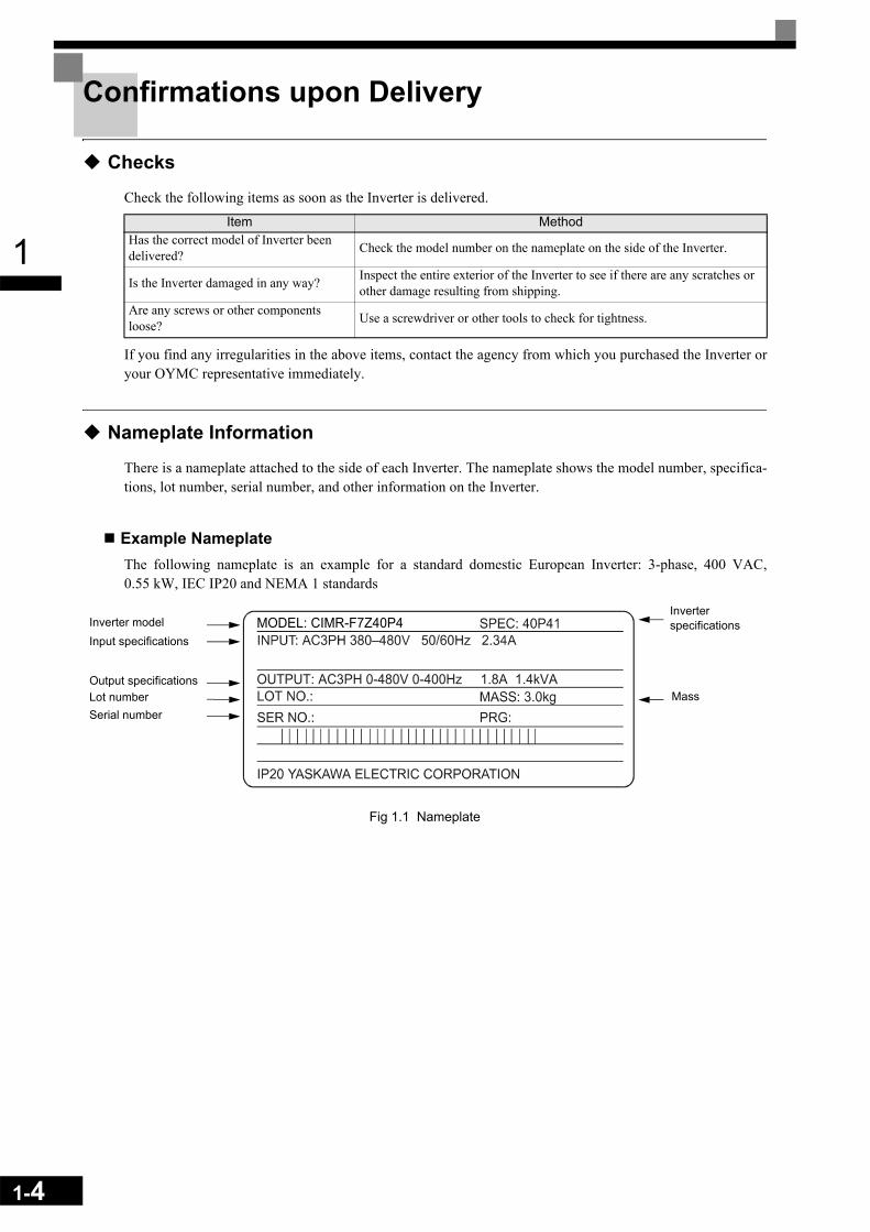
Nameplate Information
There is a nameplate attached to the side of each Inverter. The nameplate shows the model number, specifica-tions, lot number, serial number, and other information on the Inverter.
Example NameplateThe following nameplate is an example for a standard domestic European Inverter: 3-phase, 400 VAC,0.55 kW, IEC IP20 and NEMA 1 standards
Fig 1.1 Nameplate
Item MethodHas the correct model of Inverter been delivered? Check the model number on the nameplate on the side of the Inverter.
Is the Inverter damaged in any way? Inspect the entire exterior of the Inverter to see if there are any scratches or other damage resulting from shipping.
Are any screws or other components loose? Use a screwdriver or other tools to check for tightness.
Inverter modelInput specifications
Output specificationsLot numberSerial number
Inverter specifications
MassOUTPUT: AC3PH 0-480V 0-400Hz 1.8A 1.4kVA
MODEL: CIMR-F7Z40P4

1
Inverter Model NumbersThe model number of the Inverter on the nameplate indicates the specification, voltage class, and maximummotor capacity of the Inverter in alphanumeric codes.
Fig 1.2 Inverter Model Numbers
Inverter SpecificationsThe Inverter specifications (“SPEC”) on the nameplate indicate the voltage class, maximum motor capacity,the protective structure, and the revision of the Inverter in alphanumeric codes.
Fig 1.3 Inverter Specifications
CIMR – F7 Z 2 0 P4 InverterVarispeed F7
No.Z
SpecificationOYMC European. Std.
No. Voltage Class24
AC Input, 3-phase, 200 V
AC Input, 3-phase, 400 V
No. Max. Motor Capacity0P4 0.55 kW0P7 0.75 kWto to300 300 kW
“P” Indicates the decimal point.
2 0P 4 1No.24
Voltage ClassAC Input, 3-phase, 200 VAC Input, 3-phase 400 V
No. Max. Motor Capacity0P4 0.55 kW0P7 0.75 kWto to300 300 kW
No. Protective Structure0 Open chassis (IEC IP00)1 Enclosed wall-mounted (IEC IP20,
NEMA Type 1)
“P” Indicates the decimal point
1-5

1-6
1
Component Names
Inverters of 18.5 kW or LessThe external appearance and component names of the Inverter are shown in Fig 1.4. The Inverter with the ter-minal cover removed is shown in Fig 1.5.
Fig 1.4 Inverter Appearance (18.5 kW or Less)
Fig 1.5 Terminal Arrangement (18.5 kW or Less)
Top protective cover (Part of Enclosed Wall-mounted Type (IEC IP20, NEMA Type 1)
Front cover
Digital Operator
Terminal cover
Mounting
Nameplate
Diecast case
Bottom protective cover
Charge indicator
Ground terminal
Control circuit terminals
Main circuit terminals
1
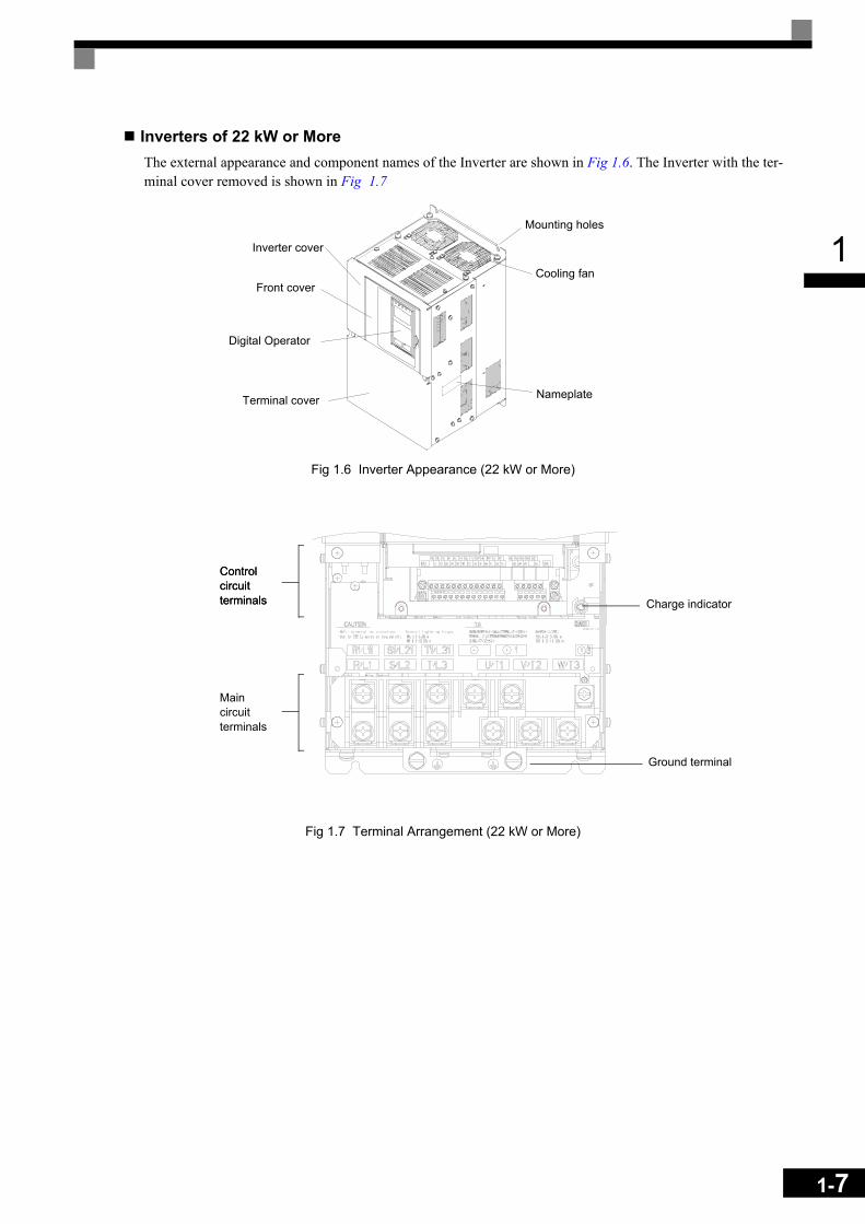
Inverters of 22 kW or MoreThe external appearance and component names of the Inverter are shown in Fig 1.6. The Inverter with the ter-minal cover removed is shown in Fig 1.7
Fig 1.6 Inverter Appearance (22 kW or More)
Fig 1.7 Terminal Arrangement (22 kW or More)
Mounting holes
Cooling fan
Nameplate
Inverter cover
Front cover
Digital Operator
Terminal cover
Controlcircuitterminals
Controlcircuitterminals
Maincircuitterminals
Ground terminal
Charge indicator
1-7
1-8
1
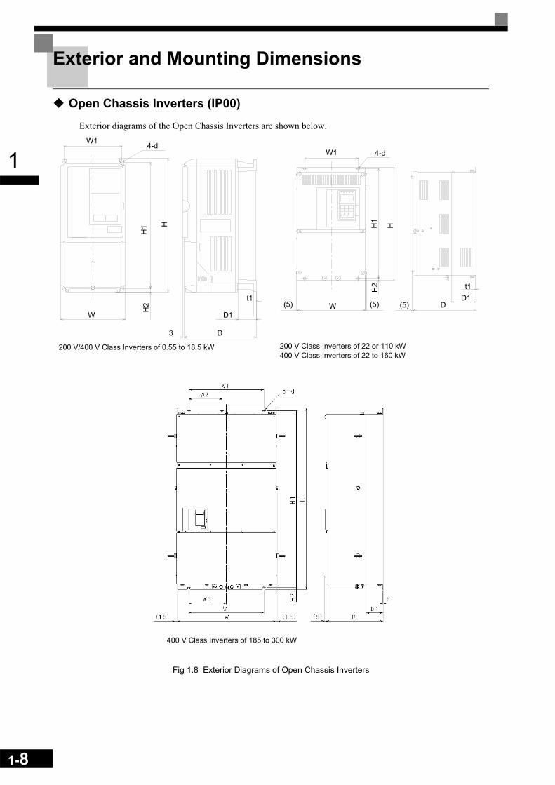
Exterior and Mounting Dimensions
Open Chassis Inverters (IP00)
Exterior diagrams of the Open Chassis Inverters are shown below.
Fig 1.8 Exterior Diagrams of Open Chassis Inverters
200 V Class Inverters of 22 or 110 kW400 V Class Inverters of 22 to 160 kW
200 V/400 V Class Inverters of 0.55 to 18.5 kW
400 V Class Inverters of 185 to 300 kW

1
Enclosed Wall-mounted Inverters (NEMA1)
Exterior diagrams of the Enclosed Wall-mounted Inverters (NEMA1) are shown below.
Fig 1.9 Exterior Diagrams of Enclosed Wall-mounted Inverters
200 V Class Inverters of 22 or 75 kW400 V Class Inverters of 22 to 160 kW
200 V/400 V Class Inverters of 0.55 to 18.5 kW
Grommet
1-9

1-10
1
* Same for Open Chassis and Enclosed Wall-mounted Inverters
Table 1.3 Inverter Dimensions (mm) and Masses (kg) of 400V Class Inverters of 185 kW to 300 kW
Table 1.2 Inverter Dimensions (mm) and Masses (kg) of F7 inverters from 0.4 to 160kW
Voltage Class
Max. Appli-cable Motor Output[kW]
Dimensions (mm) Caloric Value (W)Cool-ing Method
Open Chassis (IP00) Enclosed Wall-mounted (NEMA1)
External
Inter-nal
Total Heat Gen-era-tion
W H D W1 H1 H2 D1 t1App-rox
MassW H D W1 H0 H1 H2 H3 D1 t1
App-rox.
Mass
Mounting
Holes d*
200 V(3-phase)
0.55
140 280157
126 266 739
53
140 280157
126 280 266 70
395
3M5
20 39 59
Natu-ral
0.75 27 42 691.5 50 50 1002.2 70 59 1293.7
177 59 4 177 59 4112 74 186
Fan
5.5 164 84 2487.5
200 300 197 186 285
7.5
65.5
2.3
6200
300197 186 300 285
7.5
65.5
2.3
6
M6
219 113 33211 7 310 10 7 374 170 54415
240 350 207 216 335 78 11 240350
207 216 350 3350
78 11429 183 612
18.5 380 30 501 211 71222 250 400
258195 385
10021 250 535
258195 400 385 135
10024 586 274 860
30 275 450 220 435 24 275 615 220 450 435 165 27 865 352 121737
375 600300
250 57513
100
3.2
57380 890
300250 600 575
13210
100
3.2
62
M10
1015 411 142645 330
130
63 330130
68 1266 505 177155
450 725 350 325 70086
455 1100 350 325 725 700 305
94 1588 619 220775 87 95 2019 838 285790 500 850 360 378 820
15 4.5108
--- M122437 997 3434
110 575 885 380 445 855 140 150 2733 1242 3975
400 V(3-phase)
0.55
140 280
157
126 266 7
39
5
3
140 280
157
126 280 266 7
0
39
5
3
M5
14 39 53Natu-
ral0.75 17 41 581.5 36 48 842.2
177 59 4 177 59 4
59 56 115
Fan
3.7 80 68 1484.0 70 91 1615.5 127 82 2097.5
200 300 197 186 285
7.5
65.5
2.3
6 200 300 197 186 300 285
7.5
65.5
2.3
6
M6
193 114 30711 252 158 41015
240 350 207 216 335 78 10 240 350 207 216 350 335 78 10326 172 498
18.5 426 208 63422
275 450 258 220 435 100 21 275 535 258 220 450 43585
100 24466 259 725
30 678 317 99537
325 550 283 260 535 105 36 325635
283 260 550 535 105 40784 360 1144
45715 165
901 415 131655 1203 495 169875
450 725 350 325 700 13130
3.288
455 1100 350 325 725 700 13 305
1303.2
96M10
1399 575 197490 89 97 1614 671 2285110
500 850 360 370 820 144.5
102505 124
5 360 370 850 820 15 3954.5
122
M12
2097 853 2950132 120 130 2388 1002 3390
160 575 916 378 445 855 46 140 160 579 1324 378 445 916 855 46 408 140 170 2791 1147 3938
Voltage Class
Max. Applica-
ble Motor Output [kW]
Dimensions (mm)Open Chassis (IP00)
Caloric Value (W)
Cooling MethodExter-
nalInter-nal
Total Heat
Genera-tion
W H D W1 W2 W3 H1 H2 D1 t1App-rox.
Mass
Mount-ing
Holes d
400V(3-phase)
185710 1305 413 540 240 270 1270 15 125.5 4.5
260
M12
3237 1372 4609
Fan220 280 3740 1537 5277
300 916 1475 413 730 365 365 1440 15 125.5 4.5 405 5838 2320 8158
1
Checking and Controlling the Installation Site
Install the Inverter in the installation site described below and maintain optimum conditions.
Installation Site
Install the Inverter under the following conditions in a pollution degree 2 environment.
Protection covers are attached to the top and bottom of the Inverter. Be sure to remove the protection coversbefore installing a 200 or 400 V Class Inverter with an output of 18.5 kW or less in a panel.
Observe the following precautions when mounting the Inverter.• Install the Inverter in a clean location which is free from oil mist and dust. It can be installed in a totally
enclosed panel that is completely shielded from floating dust.• When installing or operating the Inverter, always take special care so that metal powder, oil, water, or other
foreign matter does not get into the Inverter.• Do not install the Inverter on combustible material, such as wood.• Install the Inverter in a location free from radioactive materials and combustible materials.• Install the Inverter in a location free from harmful gasses and liquids.• Install the Inverter in a location without excessive oscillation.• Install the Inverter in a location free from chlorides.• Install the Inverter in a location not in direct sunlight.
Controlling the Ambient Temperature
To enhance the reliability of operation, the Inverter should be installed in an environment free from extremetemperature increases. If the Inverter is installed in an enclosed environment, such as a box, use a cooling fanor air conditioner to maintain the internal air temperature below 45°C.
Protecting the Inverter from Foreign Matter
Place a cover over the Inverter during installation to shield it from metal power produced by drilling.
Always remove the cover from the Inverter after completing installation. Otherwise, ventilation will bereduced, causing the Inverter to overheat.
Type Ambient Operating Temperature HumidityEnclosed wall-mounted -10 to + 40 °C 95% RH or less (no condensation) Open chassis -10 to + 45 °C 95% RH or less (no condensation)
1-11
1-12
1
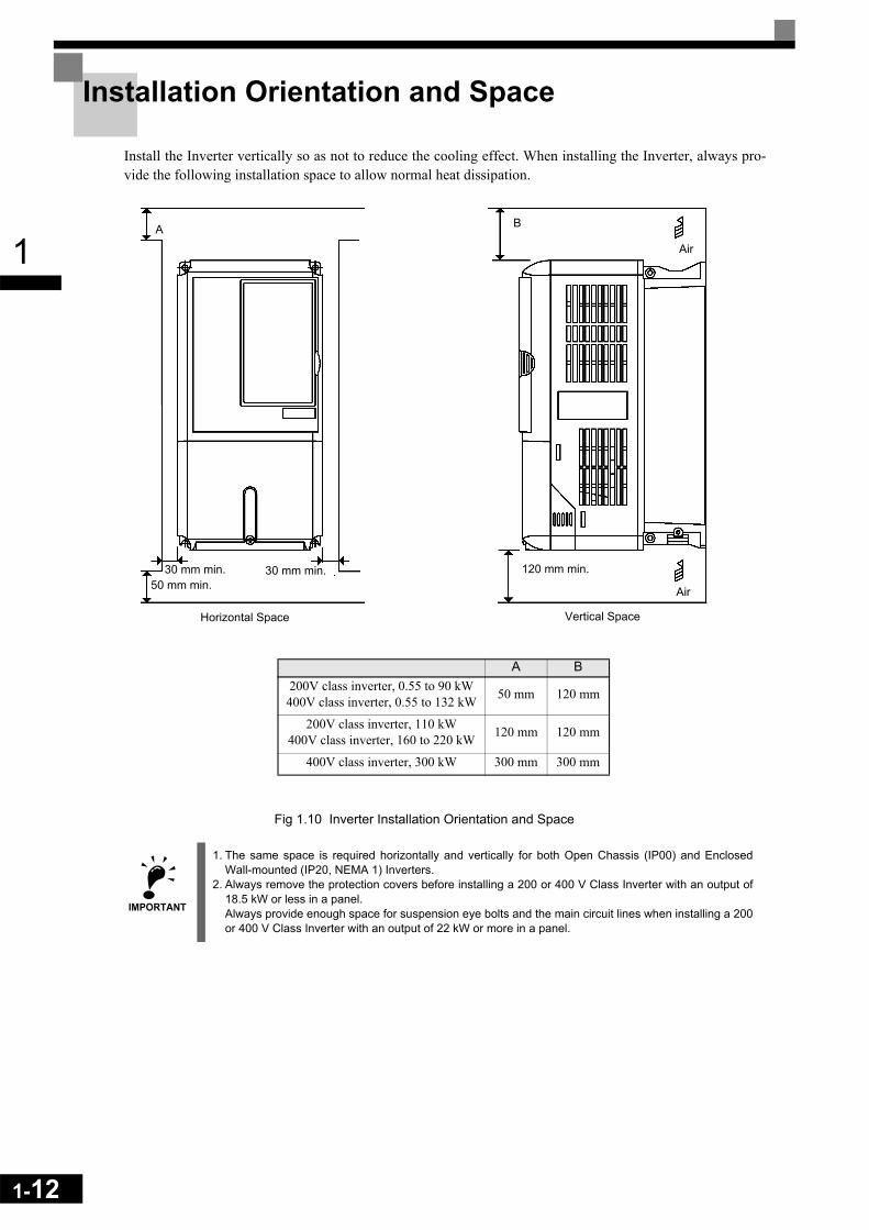
Installation Orientation and Space
Install the Inverter vertically so as not to reduce the cooling effect. When installing the Inverter, always pro-vide the following installation space to allow normal heat dissipation.
Fig 1.10 Inverter Installation Orientation and Space
IMPORTANT
1. The same space is required horizontally and vertically for both Open Chassis (IP00) and EnclosedWall-mounted (IP20, NEMA 1) Inverters.
2. Always remove the protection covers before installing a 200 or 400 V Class Inverter with an output of18.5 kW or less in a panel.Always provide enough space for suspension eye bolts and the main circuit lines when installing a 200or 400 V Class Inverter with an output of 22 kW or more in a panel.
A
50 mm min.30 mm min. 30 mm min.
B
120 mm min.
Air
Air
Vertical SpaceHorizontal Space
A B200V class inverter, 0.55 to 90 kW400V class inverter, 0.55 to 132 kW 50 mm 120 mm
200V class inverter, 110 kW400V class inverter, 160 to 220 kW 120 mm 120 mm
400V class inverter, 300 kW 300 mm 300 mm

1
Removing and Attaching the Terminal Cover
Remove the terminal cover to wire cables to the control circuit and main circuit terminals.
Removing the Terminal Cover
Inverters of 18.5 kW or LessLoosen the screw at the bottom of the terminal cover, press in on the sides of the terminal cover in the direc-tions of arrows 1, and then lift up on the terminal in the direction of arrow 2.
Fig 1.11 Removing the Terminal Cover (Model CIMR-F7Z25P5 Shown Above)
Inverters of 22 kW or MoreLoosen the screws on the left and right at the top of the terminal cover, pull out the terminal cover in the direc-tion of arrow 1 and then lift up on the terminal in the direction of arrow 2.
Fig 1.12 Removing the Terminal Cover (Model CIMR-F7Z2022 Shown Above)
Attaching the Terminal Cover
When wiring the terminal block has been completed, attach the terminal cover by reversing the removal proce-dure.
For Inverters with an output of 18.5 kW or less, insert the tab on the top of the terminal cover into the grooveon the Inverter and press in on the bottom of the terminal cover until it clicks into place.
1
21
12
1-13

1-14
1
Removing/Attaching the Digital Operator and Front Cover
Inverters of 18.5 kW or Less
To attach optional cards or change the terminal card connector, remove the Digital Operator and front cover inaddition to the terminal cover. Always remove the Digital Operator from the front cover before removing thefront cover.
The removal and attachment procedures are described below.
Removing the Digital OperatorPress the lever on the side of the Digital Operator in the direction of arrow 1 to unlock the Digital Operatorand lift the Digital Operator in the direction of arrow 2 to remove the Digital Operator as shown in the follow-ing illustration
Fig 1.13 Removing the Digital Operator (Model CIMR-F7Z45P5 Shown Above)
1
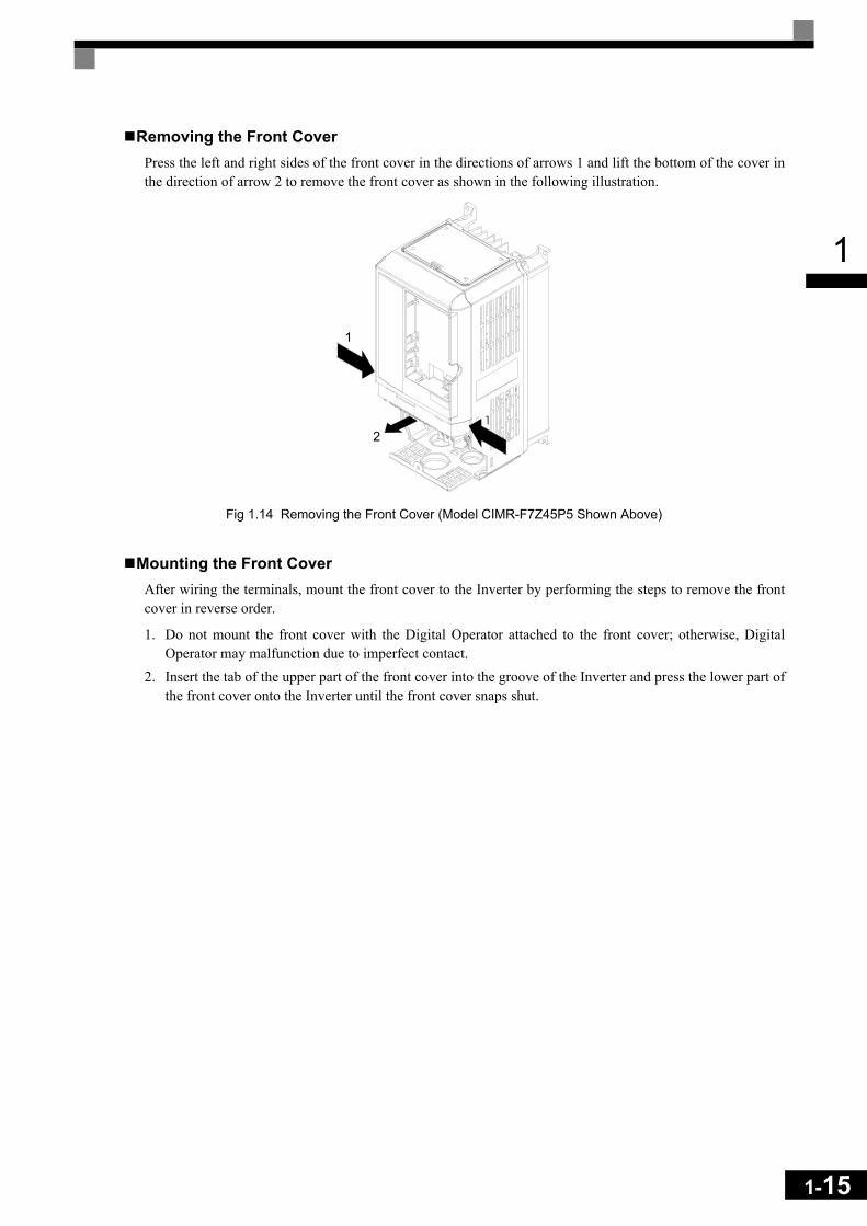
Removing the Front CoverPress the left and right sides of the front cover in the directions of arrows 1 and lift the bottom of the cover inthe direction of arrow 2 to remove the front cover as shown in the following illustration.
Fig 1.14 Removing the Front Cover (Model CIMR-F7Z45P5 Shown Above)
Mounting the Front CoverAfter wiring the terminals, mount the front cover to the Inverter by performing the steps to remove the frontcover in reverse order.
1. Do not mount the front cover with the Digital Operator attached to the front cover; otherwise, DigitalOperator may malfunction due to imperfect contact.
2. Insert the tab of the upper part of the front cover into the groove of the Inverter and press the lower part ofthe front cover onto the Inverter until the front cover snaps shut.
1
2
1-15
1-16
1
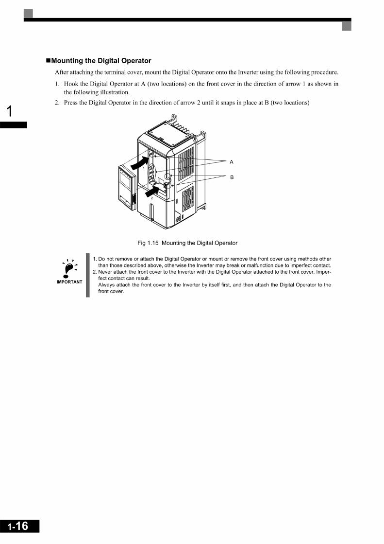
Mounting the Digital OperatorAfter attaching the terminal cover, mount the Digital Operator onto the Inverter using the following procedure.
1. Hook the Digital Operator at A (two locations) on the front cover in the direction of arrow 1 as shown inthe following illustration.
2. Press the Digital Operator in the direction of arrow 2 until it snaps in place at B (two locations)
Fig 1.15 Mounting the Digital Operator
IMPORTANT
1. Do not remove or attach the Digital Operator or mount or remove the front cover using methods otherthan those described above, otherwise the Inverter may break or malfunction due to imperfect contact.
2. Never attach the front cover to the Inverter with the Digital Operator attached to the front cover. Imper-fect contact can result.Always attach the front cover to the Inverter by itself first, and then attach the Digital Operator to thefront cover.
A
B

1
Inverters of 22 kW or More
For inverters with an output of 22 kW or more, remove the terminal cover and then use the following proce-dures to remove the Digital Operator and main cover.
Removing the Digital OperatorUse the same procedure as for Inverters with an output of 18.5 kW or less.
Removing the Front CoverLift up at the location label 1 at the top of the control circuit terminal card in the direction of arrow 2.
Fig 1.16 Removing the Front Cover (Model CIMR-F7Z2022 Shown Above)
Attaching the Front CoverAfter completing required work, such as mounting an optional card or setting the terminal card, attach thefront cover by reversing the procedure to remove it.
1. Confirm that the Digital Operator is not mounted on the front cover. Contact faults can occur if the cover isattached while the Digital Operator is mounted to it.
2. Insert the tab on the top of the front cover into the slot on the Inverter and press in on the cover until itclicks into place on the Inverter.
Attaching the Digital OperatorUse the same procedure as for Inverters with an output of 18.5 kW or less.
1
2
1-17

1-18
1
2Wiring
This chapter describes wiring terminals, main circuit terminal connections, main circuit termi-nal wiring specifications, control circuit terminals, and control circuit wiring specifications.
Connections to Peripheral Devices........................................2-2 Connection Diagram ..............................................................2-3 Terminal Block Configuration.................................................2-5 Wiring Main Circuit Terminals ................................................2-6 Wiring Control Circuit Terminals ..........................................2-20 Wiring Check........................................................................2-27 Installing and Wiring Option Cards ......................................2-28
2-2
2
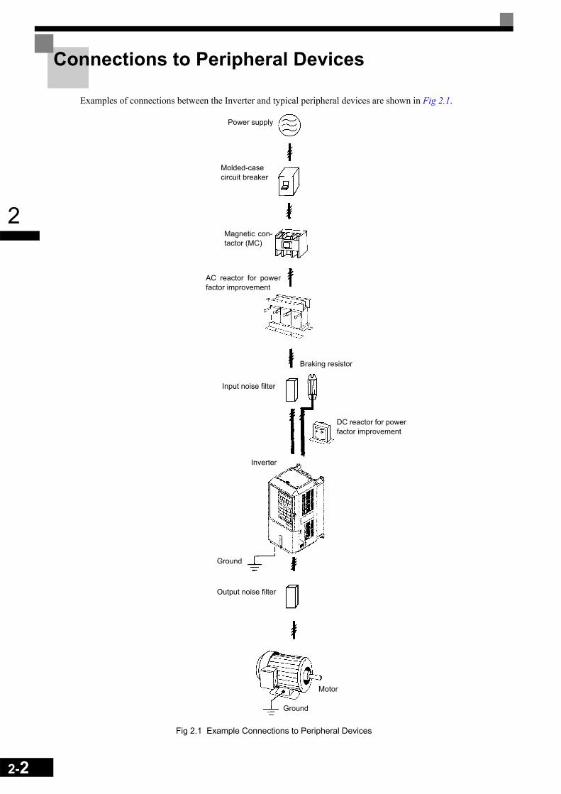
Connections to Peripheral Devices
Examples of connections between the Inverter and typical peripheral devices are shown in Fig 2.1.
Fig 2.1 Example Connections to Peripheral Devices
Power supply
Molded-casecircuit breaker
Magnetic con-tactor (MC)
AC reactor for powerfactor improvement
Braking resistor
Input noise filter
Inverter
DC reactor for powerfactor improvement
Ground
Output noise filter
Ground
Motor

2
Connection Diagram
The connection diagram of the Inverter is shown in Fig 2.2.
When using the Digital Operator, the motor can be operated by wiring only the main circuits.
Fig 2.2 Connection Diagram (Model CIMR-F7Z47P5 Shown Above)
M2
M1Contact output 1[Default : Running]
M4
M3Contact output 2[Default : Zero speed]
M6
M5Contact output 3[Default : Frequency agree 1]
MC
MB Fault contact output250 VAC, 1A max. 30 VDC, 1A max.
MA
Multi-function digitaloutput250 VAC, 1A max. 30 VDC, 1A max.
LineFilter
L1L2L3
PE
T
M3-phase power380 to 480 V
50/60 Hz
Varispeed F7CIMR-
F7C47P5
Forward Run/Stop S1
R/L1S/L2T/L3
U/T1V/T2
W/T3
Reverse Run/Stop S2
S3External fault
S4Fault reset
S5Multi-step speed setting 1
S6
S7
SN
Multi-step speed setting 2
Jog frequency selection
SC
SP24V
Multi-functiondigital inputs[Factory setting]
+V
AC
A2 Multi-function analog input 2[Default: Frequency bias4 to 20mA (250 )]
Analog input 1: Masterfrequency reference0 to +10V (20 k )
A1
0V
RP
Analog input power supply+15V, 20mA
Pulse train input [Default:Frequency reference input]0 to 32kHz
Analog input power supply-15V, 20mA
-V
E(G) Shieldterminal
PP
4 to 20mA
0 to 10V3
2k
MP
E(G)
AC
Pulse train output0 to 32kHz (2.2 k )[Default: Output frequency]
FM+ -
AM+ -
AC
AM
FM
Adjustment,20 k
Multi-function analog output 1(-10 to +10V 2mA / 4 to 20mA)[Default: Output frequency 0 to +10V]
Multi-function analog output 2(-10 to +10V 2mA / 4 to 20mA)[Default: Output current 0 to +10V]
Shieldterminal
R+
R-
S+
S-
IG
Terminatingresistance
DC reactor to improve inputpower factor (optional)
Short-circuit bar
Braking resistor unit (optional)
1 2 B1 B2
U X
Shielded wires P Twisted-pairShielded wires
MEMOBUScommunicationRS-485/422
P
P
1
2
3
21
Fuses
Main contactor
Analog input settingadjustment
Ω
2k Ω
Ω
Ω
Ω
Ω
Adjustment,20 k Ω
2-3
2-4
2
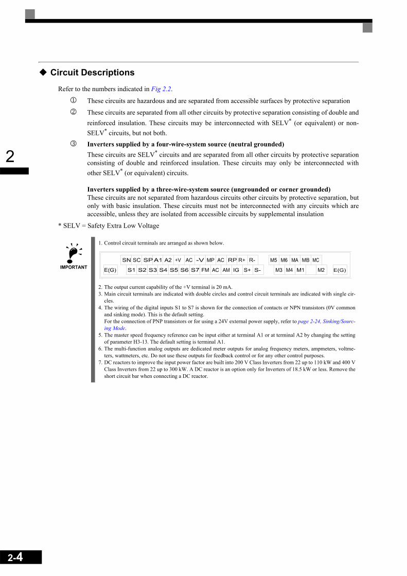
Circuit Descriptions
Refer to the numbers indicated in Fig 2.2.
1 These circuits are hazardous and are separated from accessible surfaces by protective separation
2 These circuits are separated from all other circuits by protective separation consisting of double andreinforced insulation. These circuits may be interconnected with SELV* (or equivalent) or non-SELV* circuits, but not both.
3 Inverters supplied by a four-wire-system source (neutral grounded)These circuits are SELV* circuits and are separated from all other circuits by protective separationconsisting of double and reinforced insulation. These circuits may only be interconnected withother SELV* (or equivalent) circuits.
Inverters supplied by a three-wire-system source (ungrounded or corner grounded)These circuits are not separated from hazardous circuits other circuits by protective separation, butonly with basic insulation. These circuits must not be interconnected with any circuits which areaccessible, unless they are isolated from accessible circuits by supplemental insulation
* SELV = Safety Extra Low Voltage
IMPORTANT
1. Control circuit terminals are arranged as shown below.
2. The output current capability of the +V terminal is 20 mA.3. Main circuit terminals are indicated with double circles and control circuit terminals are indicated with single cir-
cles.4. The wiring of the digital inputs S1 to S7 is shown for the connection of contacts or NPN transistors (0V common
and sinking mode). This is the default setting. For the connection of PNP transistors or for using a 24V external power supply, refer to page 2-24, Sinking/Sourc-ing Mode.
5. The master speed frequency reference can be input either at terminal A1 or at terminal A2 by changing the settingof parameter H3-13. The default setting is terminal A1.
6. The multi-function analog outputs are dedicated meter outputs for analog frequency meters, ampmeters, voltme-ters, wattmeters, etc. Do not use these outputs for feedback control or for any other control purposes.
7. DC reactors to improve the input power factor are built into 200 V Class Inverters from 22 up to 110 kW and 400 VClass Inverters from 22 up to 300 kW. A DC reactor is an option only for Inverters of 18.5 kW or less. Remove theshort circuit bar when connecting a DC reactor.

2
Terminal Block Configuration
The terminal arrangements are shown in Fig 2.3 and Fig 2.4.
Fig 2.3 Terminal Arrangement (200 V/400 V Class Inverter of 0.4 kW)
Fig 2.4 Terminal Arrangement (200 V/400 V Class Inverter of 22 kW or more)
Charge indicator
Ground terminal
Control circuit terminals
Main circuit terminals
Controlcircuitterminals
Controlcircuitterminals
Maincircuitterminals
Ground terminal
Charge indicator
2-5

2-6
2
Wiring Main Circuit Terminals
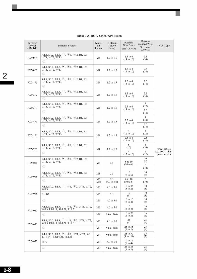
Applicable Wire Sizes and Closed-loop Connectors
Select the appropriate wires and crimp terminals from Table 2.1 and Table 2.2. Refer to instruction manualTOE-C726-2 for wire sizes for Braking Resistor Units and Braking Units
Table 2.1 200 V Class Wire Sizes
Inverter Model
CIMR-Terminal Symbol
Termi-nal
Screws
Tightening Torque(N•m)
Possible Wire Sizes
mm2(AWG)
Recom-mended Wire
Size mm2
(AWG)Wire Type
F7Z20P4R/L1, S/L2, T/L3, , 1, 2, B1, B2, U/T1, V/T2, W/T3 M4 1.2 to 1.5 1.5 to 4
(14 to 10)2.5(14)
Power cables, e.g., 600 V vinyl
power cables
F7Z20P7R/L1, S/L2, T/L3, , 1, 2, B1, B2, U/T1, V/T2, W/T3 M4 1.2 to 1.5 1.5 to 4
(14 to 10)2.5(14)
F7Z21P5R/L1, S/L2, T/L3, , 1, 2, B1, B2, U/T1, V/T2, W/T3 M4 1.2 to 1.5 1.5 to 4
(14 to 10)2.5(14)
F7Z22P2R/L1, S/L2, T/L3, , 1, 2, B1, B2, U/T1, V/T2, W/T3 M4 1.2 to 1.5 1.5 to 4
(14 to 10)2
(14)
F7Z23P7R/L1, S/L2, T/L3, , 1, 2, B1, B2, U/T1, V/T2, W/T3 M4 1.2 to 1.5 4
(12 to 10)4
(12)
F7Z25P5R/L1, S/L2, T/L3, , 1, 2, B1, B2, U/T1, V/T2, W/T3 M4 1.2 to 1.5 6
(10)6
(10)
F7Z27P5R/L1, S/L2, T/L3, , 1, 2, B1, B2, U/T1, V/T2, W/T3 M5 2.5 10
(8 to 6)10(8)
F7Z2011R/L1, S/L2, T/L3, , 1, 2, B1, B2, U/T1, V/T2, W/T3 M5 2.5 16
(6 to 4)16(6)
F7Z2015
R/L1, S/L2, T/L3, , 1, 2, U/T1, V/T2, W/T3
M6 4.0 to 5.0 25(4 to 2)
25(4)
B1, B2 M5 2.5 10(8 to 6) -
M6 4.0 to 5.0 25(4)
25(4)
F7Z2018
R/L1, S/L2, T/L3, , 1, 2, U/T1, V/T2, W/T3
M8 9.0 to 10.0 25 to 35(3 to 2)
25(3)
B1, B2 M5 2.5 10(8 to 6) -
M6 4.0 to 5.0 25(4)
25(4)
F7Z2022
R/L1, S/L2, T/L3, , 1, U/T1, V/T2, W/T3, R1/L11, S1/L21, T1/L31
M8 9.0 to 10.0 25 to 35(3 to 1)
25(3)
3 M6 4.0 to 5.0 10 to 16(8 to 4) -
M8 9.0 to 10.0 25 to 35(4 to 2)
25(4)
F7Z2030
R/L1, S/L2, T/L3, , 1 U/T1, V/T2, W/T3, R1/L11, S1/L21, T1/L31
M8 9.0 to 10.0 50(1 to 1/0)
50(1)
3 M6 4.0 to 5.0 10 to 16(8 to 4) -
M8 9.0 to 10.0 25 to 35(4 to 2)
25(4)

2
* The wire thickness is set for copper wires at 75°C
F7Z2037
R/L1, S/L2, T/L3, , 1 U/T1, V/T2, W/T3, R1/L11, S1/L21, T1/L31
M10 17.6 to 22.5 70 to 95(2/0 to 4/0)
70(2/0)
Power cables, e.g., 600 V vinyl
power cables
3 M8 8.8 to 10.8 6 to 16(10 to 4) –
M10 17.6 to 22.5 35 to 70(2 to 2/0)
35(2)
r/l1, ∆/l2 M4 1.3 to 1.4 0.5 to 4(20 to 10)
1.5(16)
F7Z2045
R/L1, S/L2, T/L3, , 1 U/T1, V/T2, W/T3, R1/L11, S1/L21, T1/L31
M10 17.6 to 22.5 95(3/0 to 4/0)
95(3/0)
3 M8 8.8 to 10.8 6 to 16(10 to 4) –
M10 17.6 to 22.5 50 to 70(1 to 2/0)
50(1)
r/l1, ∆/l2 M4 1.3 to 1.4 0.5 to 4(20 to 10)
1.5(16)
F7Z2055
R/L1, S/L2, T/L3, , 1 M12 31.4 to 39.2 50 to 95(1/0 to 4/0)
50 × 2P(1/0 × 2P)
U/T1, V/T2, W/T3, R1/L11, S1/L21, T1/L31 M10 17.6 to 22.5 90(4/0)
90(4/0)
3 M8 8.8 to 10.8 6 to 70(10 to 2/0) –
M10 17.6 to 22.5 35 to 95(3 to 4/0)
50(1/0)
r/l1, ∆/l2 M4 1.3 to 1.4 0.5 to 4(20 to 10)
1.5(16)
F7Z2075
R/L1, S/L2, T/L3, , 1 M12 31.4 to 39.2 95 to 122(3/0 to 250)
95 × 2P(3/0 × 2P)
U/T1, V/T2, W/T3, R1/L11, S1/L21, T1/L31 M10 17.6 to 22.5 95(3/0 to 4/0)
95 × 2P(3/0 × 2P)
3 M8 8.8 to 10.8 6 to 70(10 to 2/0) –
M10 17.6 to 22.5 95 to 185(3/0 to 400)
95(3/0)
r/l1, ∆/l2 M4 1.3 to 1.4 0.5 to 4(20 to 10)
1.5(16)
F7Z2090
R/L1, S/L2, T/L3, , 1 M12 31.4 to 39.2
150 to 185(250 to 400)
150 × 2P(250 × 2P)
U/T1, V/T2, W/T3, R1/L11, S1/L21, T1/L31 95 to 150(4/0 to 300)
95 × 2P(4/0 × 2P)
3 M8 8.8 to 10.8 6 to 70(10 to 2/0) –
M12 31.4 to 39.2 70 to 150(2/0 to 300)
70 × 2P(2/0 × 2P)
r/l1, ∆/l2 M4 1.3 to 1.4 0.5 to 4(20 to 10)
1.5(16)
F7Z2110
R/L1, S/L2, T/L3, , 1
M12 31.4 to 39.2
240 to 300(350 to 600)
240 × 2P, or 50 × 4P
(350 × 2P, or 1/0 × 2P)
U/T1, V/T2, W/T3, R1/L11, S1/L21, T1/L31 150 to 300(300 to 600)
150 × 2P, or 50 × 4P
(300 × 2P, or 1/0 × 4P)
3 M8 8.8 to 10.8 6 to 70(10 to 2/0) –
M12 31.4 to 39.2 150(300)
150 × 2P(300 × 2P)
r/l1, ∆/l2 M4 1.3 to 1.4 0.5 to 4(20 to 10)
1.5(16)
Table 2.1 200 V Class Wire Sizes
Inverter Model
CIMR-Terminal Symbol
Termi-nal
Screws
Tightening Torque(N•m)
Possible Wire Sizes
mm2(AWG)
Recom-mended Wire
Size mm2
(AWG)Wire Type
2-7
2-8
2
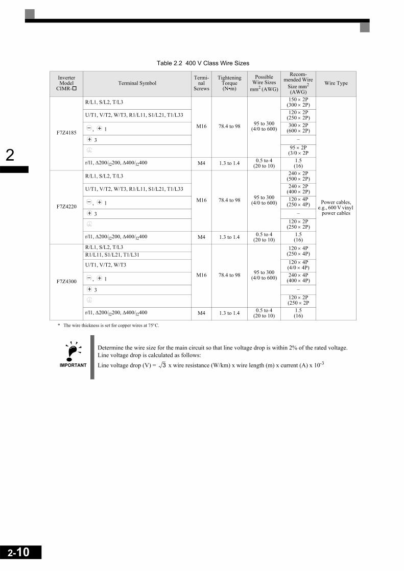
Table 2.2 400 V Class Wire Sizes
Inverter Model
CIMR-Terminal Symbol
Termi-nal
Screws
Tightening Torque(N•m)
Possible Wire Sizes
mm2 (AWG)
Recom-mended Wire
Size mm2
(AWG)Wire Type
F7Z40P4R/L1, S/L2, T/L3, , 1, 2, B1, B2, U/T1, V/T2, W/T3 M4 1.2 to 1.5 1.5 to 4
(14 to 10)2.5(14)
Power cables, e.g., 600 V vinyl
power cables
F7Z40P7R/L1, S/L2, T/L3, , 1, 2, B1, B2, U/T1, V/T2, W/T3 M4 1.2 to 1.5 1.5 to 4
(14 to 10)2.5(14)
F7Z41P5R/L1, S/L2, T/L3, , 1, 2, B1, B2, U/T1, V/T2, W/T3 M4 1.2 to 1.5 1.5 to 4
(14 to 10)2.5(14)
F7Z42P2R/L1, S/L2, T/L3, , 1, 2, B1, B2, U/T1, V/T2, W/T3 M4 1.2 to 1.5 1.5 to 4
(14 to 10)2.5(14)
F7Z43P7R/L1, S/L2, T/L3, , 1, 2, B1, B2, U/T1, V/T2, W/T3 M4 1.2 to 1.5 2.5 to 4
(14 to 10)
4(12)2.5(14)
F7Z44P0R/L1, S/L2, T/L3, , 1, 2, B1, B2, U/T1, V/T2, W/T3 M4 1.2 to 1.5 2.5 to 4
(14 to 10)
4(12)2.5(14)
F7Z45P5R/L1, S/L2, T/L3, , 1, 2, B1, B2, U/T1, V/T2, W/T3 M4 1.2 to 1.5
4(12 to 10)
4(12)
2.5 to 4(14 to 10)
2.5(14)
F7Z47P5R/L1, S/L2, T/L3, , 1, 2, B1, B2, U/T1, V/T2, W/T3 M4 1.2 to 1.5
6(10)
6(10)
4(12 to 10)
4(12)
F7Z4011R/L1, S/L2, T/L3, , 1, 2, B1, B2, U/T1, V/T2, W/T3 M5 2.5 6 to 10
(10 to 6)
10(8)6
(10)
F7Z4015R/L1, S/L2, T/L3, , 1, 2, B1, B2, U/T1, V/T2, W/T3
M5 2.5 10(8 to 6)
10(8)
M5(M6)
2.5(4.0 to 5.0)
6 to 10(10 to 6)
6(10)
F7Z4018
R/L1, S/L2, T/L3, , 1, 2, U/T1, V/T2, W/T3
M6 4.0 to 5.0 10 to 35(8 to 2)
10(8)
B1, B2 M5 2.5 10(8)
10(8)
M6 4.0 to 5.0 10 to 16(8 to 4)
10(8)
F7Z4022R/L1, S/L2, T/L3, , 1, 3, U/T1, V/T2, W/T3, R1/L11, S1/L21, T1/L31
M6 4.0 to 5.0 16(6 to 4)
16(6)
M8 9.0 to 10.0 16 to 25(6 to 2)
16(6)
F7Z4030R/L1, S/L2, T/L3, , 1, 3, U/T1, V/T2, W/T3, R1/L11, S1/L21, T1/L31
M6 4.0 to 5.0 25(4)
25(4)
M8 9.0 to 10.0 25 to 35(4 to 2)
25(4)
F7Z4037
R/L1, S/L2, T/L3, , 1, U/T1, V/T2, W/T3, R1/L11, S1/L21, T1/L31
M8 9.0 to 10.0 25 to 50(4 to 1/0)
35(2)
3 M6 4.0 to 5.0 10 to 16(8 to 4) -
M8 9.0 to 10.0 25 to 35(4 to 2)
25(4)

2
F7Z4045
R/L1, S/L2, T/L3, , 1, U/T1, V/T2, W/T3, R1/L11, S1/L21, T1/L31
M8 9.0 to 10.0 35 to 50(2 to 1/0)
35(2)
Power cables, e.g., 600 V vinyl
power cables
3 M6 4.0 to 5.0 10 to 16(8 to 4) -
M8 9.0 to 10.0 25 to 35(4 to 2)
25(4)
F7Z4055
R/L1, S/L2, T/L3, , 1, U/T1, V/T2, W/T3, R1/L11, S1/L21, T1/L31
M8 9.0 to 10.0 50(1 to 1/0)
50(1)
3 M6 4.0 to 5.0 10 to 16(8 to 4) -
M8 9.0 to 10.0 25 to 35(4 to 2)
25(4)
F7Z4075
R/L1, S/L2, T/L3, , 1 M10 31.4 to 39.2 70 to 95(2/0 to 4/0)
70(2/0)
U/T1, V/T2, W/T3, R1/L11, S1/L21, T1/L31 M10 17.6 to 22.5 50 to 100(1/0 to 4/0)
50(1/0)
3 M8 8.8 to 10.8 6 to 16(10 to 4) -
M10 31.4 to 39.2 35 to 70(2 to 2/0)
35(2)
r/l1, ∆200/l2200, ∆400/l2400 M4 1.3 to 1.4 0.5 to 4(20 to 10)
1.5(16)
F7Z4090
R/L1, S/L2, T/L3, , 1 M10 31.4 to 39.2 95 (3/0 to 4/0)
95(4/0)
U/T1, V/T2, W/T3, R1/L11, S1/L21, T1/L31 M10 17.6 to 22.5 95 (3/0 to 4/0)
95(4/0)
3 M8 8.8 to 10.8 10 to 16 (8 to 4) -
M10 31.4 to 39.2 50 to 95 (1 to 4/0)
50(1)
r/l1, ∆200/l2200, ∆400/l2400 M4 1.3 to 1.4 0.5 to 4(20 to 10)
1.5(16)
F7Z4110
R/L1, S/L2, T/L3, , 1 M10 31.4 to 39.2 50 to 95(1/0 to 4/0)
50 × 2P(1/0 × 2P)U/T1, V/T2, W/T3, R1/L11, S1/L21, T1/L31
3 M8 8.8 to 10.8 10 to 70(8 to 2/0) -
M12 31.4 to 39.2 70 to 150(2/0 to 300)
70(2/0)
r/l1, ∆200/l2200, ∆400/l2400 M4 1.3 to 1.4 0.5 to 4(20 to 10)
1.5(16)
F7Z4132
R/L1, S/L2, T/L3, , 1 M10 31.4 to 39.2
95(3/0 to 4/0)
95 × 2P(3/0 × 2P)
U/T1, V/T2, W/T3, R1/L11, S1/L21, T1/L31 75 to 95(2/0 to 4/0)
75 × 2P(2/0 × 2P)
3 M8 8.8 to 10.8 10 to 70(8 to 2/0) -
M12 31.4 to 39.2 95 to 150(4/0 to 300)
95(4/0)
r/l1, ∆200/l2200, ∆400/l2400 M4 1.3 to 1.4 0.5 to 4(20 to 10)
1.5(16)
F7Z4160
R/L1, S/L2, T/L3, , 1 M12 31.4 to 39.2
95 to 185(4/0 to 400)
95 × 2P(4/0 × 2P)
U/T1, V/T2, W/T3, R1/L11, S1/L21, T1/L31 95 to 185(3/0 to 400)
95 × 2P(3/0 × 2P)
3 M8 8.8 to 10.8 10 to 70(8 to 2/0) -
M12 31.4 to 39.2 50 to 150(1/0 to 300)
50 × 2P(1/0 × 2P)
r/l1, ∆200/l2200, ∆400/l2400 M4 1.3 to 1.4 0.5 to 4(20 to 10)
1.5(16)
Table 2.2 400 V Class Wire Sizes
Inverter Model
CIMR-Terminal Symbol
Termi-nal
Screws
Tightening Torque(N•m)
Possible Wire Sizes
mm2 (AWG)
Recom-mended Wire
Size mm2
(AWG)Wire Type
2-9
2-10
2
* The wire thickness is set for copper wires at 75°C.
F7Z4185
R/L1, S/L2, T/L3
M16 78.4 to 98 95 to 300(4/0 to 600)
150 × 2P(300 × 2P)
Power cables, e.g., 600 V vinyl
power cables
U/T1, V/T2, W/T3, R1/L11, S1/L21, T1/L33 120 × 2P(250 × 2P)
, 1 300 × 2P
(600 × 2P)
3 –95 × 2P
(3/0 × 2P
r/l1, ∆200/l2200, ∆400/l2400 M4 1.3 to 1.4 0.5 to 4(20 to 10)
1.5(16)
F7Z4220
R/L1, S/L2, T/L3
M16 78.4 to 98 95 to 300(4/0 to 600)
240 × 2P(500 × 2P)
U/T1, V/T2, W/T3, R1/L11, S1/L21, T1/L33 240 × 2P(400 × 2P)
, 1 120 × 4P
(250 × 4P)
3 –120 × 2P
(250 × 2P)
r/l1, ∆200/l2200, ∆400/l2400 M4 1.3 to 1.4 0.5 to 4(20 to 10)
1.5(16)
F7Z4300
R/L1, S/L2, T/L3
M16 78.4 to 98 95 to 300(4/0 to 600)
120 × 4P(250 × 4P)R1/L11, S1/L21, T1/L31
U/T1, V/T2, W/T3 120 × 4P(4/0 × 4P)
, 1 240 × 4P
(400 × 4P)
3 –120 × 2P(250 × 2P
r/l1, ∆200/l2200, ∆400/l2400 M4 1.3 to 1.4 0.5 to 4(20 to 10)
1.5(16)
IMPORTANT
Determine the wire size for the main circuit so that line voltage drop is within 2% of the rated voltage. Line voltage drop is calculated as follows:
Line voltage drop (V) = x wire resistance (W/km) x wire length (m) x current (A) x 10-3
Table 2.2 400 V Class Wire Sizes
Inverter Model
CIMR-Terminal Symbol
Termi-nal
Screws
Tightening Torque(N•m)
Possible Wire Sizes
mm2 (AWG)
Recom-mended Wire
Size mm2
(AWG)Wire Type
3
2
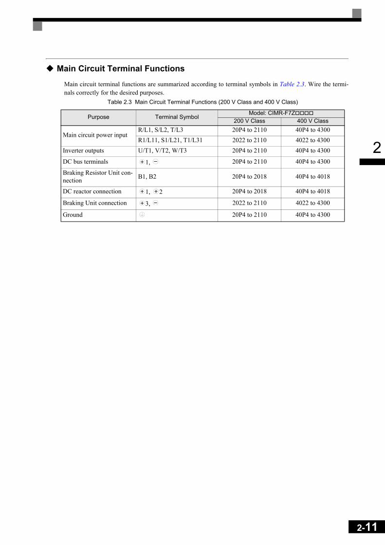
Main Circuit Terminal Functions
Main circuit terminal functions are summarized according to terminal symbols in Table 2.3. Wire the termi-nals correctly for the desired purposes.
Table 2.3 Main Circuit Terminal Functions (200 V Class and 400 V Class)
Purpose Terminal SymbolModel: CIMR-F7Z
200 V Class 400 V Class
Main circuit power inputR/L1, S/L2, T/L3 20P4 to 2110 40P4 to 4300R1/L11, S1/L21, T1/L31 2022 to 2110 4022 to 4300
Inverter outputs U/T1, V/T2, W/T3 20P4 to 2110 40P4 to 4300
DC bus terminals 1, 20P4 to 2110 40P4 to 4300
Braking Resistor Unit con-nection B1, B2 20P4 to 2018 40P4 to 4018
DC reactor connection 1, 2 20P4 to 2018 40P4 to 4018
Braking Unit connection 3, 2022 to 2110 4022 to 4300
Ground 20P4 to 2110 40P4 to 4300
2-11
2-12
2
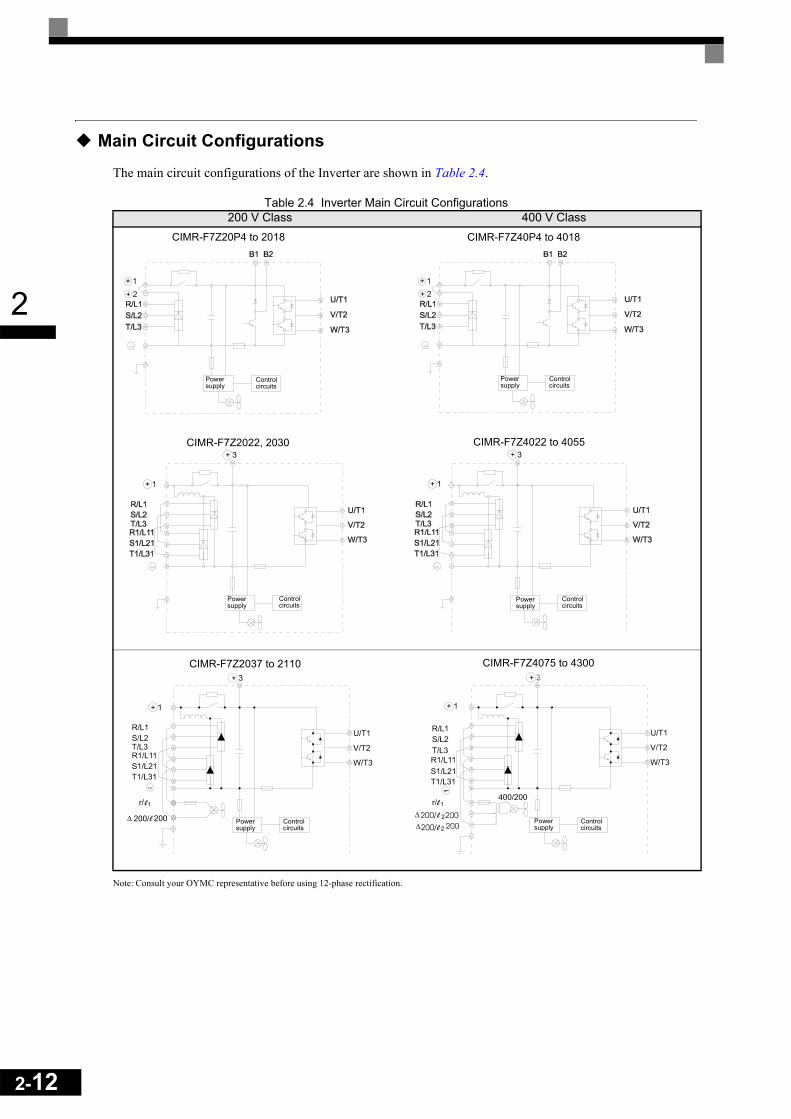
Main Circuit Configurations
The main circuit configurations of the Inverter are shown in Table 2.4.
Table 2.4 Inverter Main Circuit Configurations
Note: Consult your OYMC representative before using 12-phase rectification.
200 V Class 400 V Class
Powersupply
Controlcircuits
CIMR-F7Z20P4 to 2018
Powersupply
Controlcircuits
CIMR-F7Z40P4 to 4018
CIMR-F7Z2022, 2030
Powersupply
Controlcircuits
CIMR-F7Z4022 to 4055
Powersupply
Controlcircuits
CIMR-F7Z2037 to 2110
Powersupply
Controlcircuits
CIMR-F7Z4075 to 4300
Powersupply
Controlcircuits
2
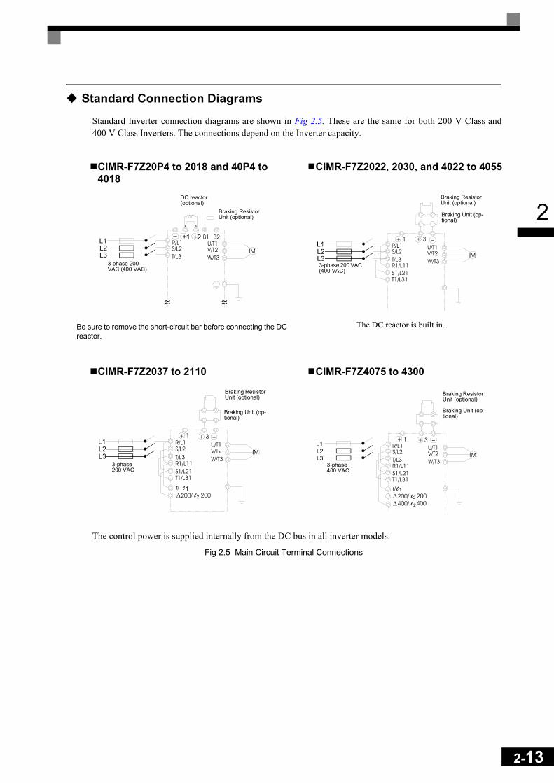
Standard Connection Diagrams
Standard Inverter connection diagrams are shown in Fig 2.5. These are the same for both 200 V Class and400 V Class Inverters. The connections depend on the Inverter capacity.
The control power is supplied internally from the DC bus in all inverter models.
Fig 2.5 Main Circuit Terminal Connections
CIMR-F7Z20P4 to 2018 and 40P4 to 4018
Be sure to remove the short-circuit bar before connecting the DC reactor.
CIMR-F7Z2022, 2030, and 4022 to 4055
The DC reactor is built in.
CIMR-F7Z2037 to 2110 CIMR-F7Z4075 to 4300
DC reactor (optional)
3-phase 200 VAC (400 VAC)
Braking Resistor Unit (optional) Braking Unit (op-
tional)
Braking Resistor Unit (optional)
3-phase 200 VAC (400 VAC)
3-phase 200 VAC
Braking Unit (op-tional)
Braking Resistor Unit (optional)
3-phase 400 VAC
Braking Unit (op-tional)
Braking Resistor Unit (optional)
2-13

2-14
2
Wiring the Main Circuits
This section describes wiring connections for the main circuit inputs and outputs.
Wiring Main Circuit InputsObserve the following precautions for the main circuit power supply input.
Installing FusesTo protect the inverter, it is recommended to use semiconductor fuses like they are shown in the table below.
Table 2.5 Input Fuses
Inverter Type
FUSEVoltage (V) Current (A) I2t (A2s)
20P4 240 10 12~2520P7 240 10 12~2521P5 240 15 23~5522P2 240 20 34~9823P7 240 30 82~22025P5 240 40 220~61027P5 240 60 290~13002011 240 80 450~50002015 240 100 1200~72002018 240 130 1800~72002022 240 150 870~162002030 240 180 1500~230002037 240 240 2100~190002045 240 300 2700~550002055 240 350 4000~550002075 240 450 7100~640002090 240 550 11000~640002110 240 600 13000~83000
40P4 480 5 6~5540P7 480 5 6~5541P5 480 10 10~5542P2 480 10 18~5543P7 480 15 34~7244P0 480 20 50~57045P5 480 25 100~57047P5 480 30 100~6404011 480 50 150~13004015 480 60 400~18004018 480 70 700~41004022 480 80 240~58004030 480 100 500~58004037 480 125 750~58004045 480 150 920~130004055 480 150 1500~130004075 480 250 3000~550004090 480 300 3800~550004110 480 350 5400~230004132 480 400 7900~640004160 480 450 14000~2500004185 480 600 20000~2500004220 480 700 34000~4000004300 480 900 52000~920000

2
Installing a Moulded-case Circuit BreakerWhen connecting the power input terminals (R/L1, S/L2, and T/L3) to the power supply using a moulded-casecircuit breaker (MCCB) observe that the circuit breaker is suitable for the Inverter.
• Choose an MCCB with a capacity of 1.5 to 2 times of the inverter's rated current.• For the MCCB's time characteristics, be sure to consider the inverter's overload protection (one minute at
150% of the rated output current).
Installing an Earth Leakage BreakerInverter outputs use high-speed switching, so high-frequency leakage current is generated. If an earth leakagebreaker should be used, select one that detects only the leakage current which is in the frequency range that ishazardous to humans but not high-frequency leakage currents.
• For a special-purpose earth leakage breaker for Inverters, choose one with a sensitivity amperage of atleast 30 mA per Inverter.
• When using a general earth leakage breaker, choose one with a sensitivity amperage of 200 mA or moreper Inverter and with an operating time of 0.1 s or more.
Installing a Magnetic ContactorIf the power supply for the main circuit is to be shut off by a control circuit, a magnetic contactor can be used.
The following things should be considered:• The Inverter can be started and stopped by opening and closing the magnetic contactor on the primary side.
Frequently opening and closing the magnetic contactor, however, may cause the Inverter to break down.Do not exceed one power upper hour.
• When the Inverter is operated with the Digital Operator, automatic operation cannot be performed afterrecovery from a power interruption.
Connecting Input Power Supply to the Terminal BlockInput power supply can be connected to any terminal R, S or T on the terminal block; the phase sequence ofinput power supply is irrelevant to the output phase sequence.
Installing an AC Reactor If the Inverter is connected to a large-capacity power transformer (600 kW or more) or a phase advancingcapacitor is switched, an excessive peak current may flow through the input power circuit, causing the inverterunit to break down.
To prevent this, install an optional AC Reactor on the input side of the Inverter or a DC reactor to the DC reac-tor connection terminals.
This also improves the power factor on the power supply side.
Installing a Surge AbsorberAlways use a surge absorber or diode for inductive loads near the Inverter. These inductive loads include mag-netic contactors, electromagnetic relays, solenoid valves, solenoids, and magnetic brakes.
2-15
2-16
2
Wiring the Output Side of Main CircuitObserve the following precautions when wiring the main output circuits.
Connecting the Inverter and MotorConnect output terminals U/T1, V/T2, and W/T3 respective to the motor lead wires U, V, and W.
Check that the motor rotates forward with the forward run command. Switch over any two of the output termi-nals to each other and reconnect if the motor rotates in reverse with the forward run command.
Never Connect a Power Supply to Output TerminalsNever connect a power supply to output terminals U/T1, V/T2, and W/T3. If voltage is applied to the outputterminals, the internal circuits of the Inverter will be damaged.
Never Short or Ground Output TerminalsIf the output terminals are touched with bare hands or the output wires come into contact with the Invertercase, an electric shock or grounding may occur. This is extremely hazardous. Do not short the output wires.
Do Not Use a Phase Advancing CapacitorNever connect a phase advancing capacitor to an output circuit. The high-frequency components of theInverter output may overheat and be damaged and may cause other parts to burn.
Do Not Use an Electromagnetic SwitchNever connect an electromagnetic switch (MC) between the Inverter and motor and turn it ON or OFF duringoperation. If the MC is turned ON while the Inverter is operating, a large inrush current will be created and theinverter’s overcurrent protection will operate.
When using a MC to switch for instance between two motors, stop the Inverter output before operating theMC.
Installing a Thermal Overload Relay Contact for Motor ProtectionThis Inverter has an electronic thermal protection function to protect the motor from overheating. If, however,more than one motor is operated with one Inverter or a multi-polar motor is used, always install a thermalrelay (THR) between the Inverter and the motor and set L1-01 to 0 (no motor protection). The control circuitshould be designed so that the contacts of the thermal overload relay turn OFF the magnetic contactor on themain circuit inputs.
Cable Length between Inverter and MotorIf the cable between the Inverter and the motor is long, the high-frequency leakage current will increase, caus-ing the Inverter output current to increase as well. This may affect peripheral devices. To prevent this, adjustthe carrier frequency (set in C6-01, C6-02) as shown in Table 2.6. (For details, refer to Chapter 5 User Param-eters.)
Table 2.6 Cable Length between Inverter and Motor
Cable length 50 m max. 100 m max. More than 100 mCarrier frequency 15 kHz max. 10 kHz max. 5 kHz max.

2
Ground WiringObserve the following precautions when wiring the ground line.
• Always use the ground terminal of the 200 V Inverter with a ground resistance of less than 100 Ω and thatof the 400 V Inverter with a ground resistance of less than 10 Ω.
• Do not share the ground wire with other devices, such as welding machines or power tools.• Always use a ground wire that complies with technical standards on electrical equipment and minimize the
length of the ground wire.Leakage current flows through the Inverter. Therefore, if the distance between the ground electrode andthe ground terminal is too long, potential on the ground terminal of the Inverter will become unstable.
• When using more than one Inverter, be careful not to loop the ground wire.
Fig 2.6 Ground Wiring
Connecting a Inverter Back Mounted Braking ResistorA Braking Resistor mounted to back side of the Inverter can be used with 200 V and 400 V Class Inverterswith outputs from 0.4 to 11 kW. If this type of resistor is used, the internal braking resistor overheat protectioncan be enabled (see Table below).
Connect the braking resistor as shown in Fig 2.7.
Fig 2.7 Connecting the Braking Resistor
L8-01 (Protection selection for internal DB resistor) 1 (Enable overheat protection)
L3-04 (Stall prevention selection during deceleration)(Select either of them.)
0 (Disable stall prevention function)
3 (Enable stall prevention function with braking resistor)
IMPORTANT
The braking resistor connection terminals are B1 and B2. Do not connect the resistor to any other termi-nals. Otherwise the resistor and other equipment may get damaged
OK NO
Inverter Braking resistor
2-17
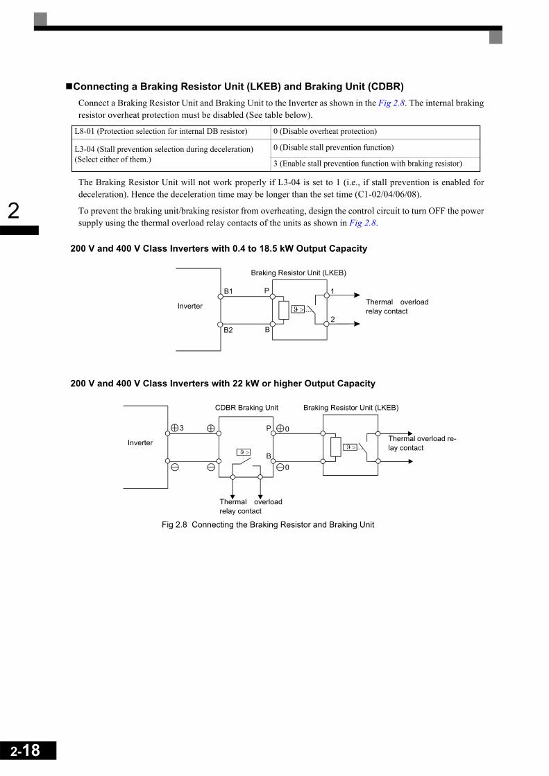
2-18
2
Connecting a Braking Resistor Unit (LKEB) and Braking Unit (CDBR)Connect a Braking Resistor Unit and Braking Unit to the Inverter as shown in the Fig 2.8. The internal brakingresistor overheat protection must be disabled (See table below).
The Braking Resistor Unit will not work properly if L3-04 is set to 1 (i.e., if stall prevention is enabled fordeceleration). Hence the deceleration time may be longer than the set time (C1-02/04/06/08).
To prevent the braking unit/braking resistor from overheating, design the control circuit to turn OFF the powersupply using the thermal overload relay contacts of the units as shown in Fig 2.8.
200 V and 400 V Class Inverters with 0.4 to 18.5 kW Output Capacity
200 V and 400 V Class Inverters with 22 kW or higher Output Capacity
Fig 2.8 Connecting the Braking Resistor and Braking Unit
L8-01 (Protection selection for internal DB resistor) 0 (Disable overheat protection)
L3-04 (Stall prevention selection during deceleration)(Select either of them.)
0 (Disable stall prevention function)
3 (Enable stall prevention function with braking resistor)
Inverter
Braking Resistor Unit (LKEB)
Thermal overloadrelay contact
Inverter
Braking Resistor Unit (LKEB)
Thermal overloadrelay contact
CDBR Braking Unit
Thermal overload re-lay contact

2
Connecting Braking Units in ParallelWhen connecting two or more Braking Units in parallel, use the wiring and jumper settings like shown inFig 2.9. There is a jumper for selecting whether each Braking Unit is to be a master or slave. Select “Master”for the first Braking Unit only, and select “Slave” for all other Braking Units (i.e. from the second Unitonwards).
Fig 2.9 Connecting Braking Units in Parallel
Inverter
Thermal overload relay contact Thermal overload relay contact Thermal overload relay contact
Braking Resistor Unit (LKEB)
Braking Resistor Unit (LKEB)
Braking Resistor Unit (LKEB)
Leve
l de-
tect
or
Braking Unit #2 Braking Unit #3
Braking Unit #1Thermal overload relay
contactThermal overload relay
contactThermal overload relay
contact
2-19

2-20
2
Wiring Control Circuit Terminals
Wire Sizes
For remote operation using analog signals, keep the control line length between the Analog Operator or oper-ation signals and the Inverter to 50 m or less, and separate the lines from main power lines or other control cir-cuits to reduce induction from peripheral devices.
When setting frequencies from an external frequency source (and not from a Digital Operator), use shieldedtwisted-pair wires and ground the shield for the largest area of contact between shield and ground.
The terminal numbers and the appropriate wire sizes are shown in Table 2.7.
* 1. Use shielded twisted-pair cables to input an external frequency reference. * 2. We recommend using straight solderless terminal on signal lines to simplify wiring and improve reliability.
Straight Solderless Terminals for Signal LinesModels and sizes of straight solderless terminal are shown in the following table.
Fig 2.10 Straight Solderless Terminal Sizes
Table 2.7 Terminal Numbers and Wire Sizes (Same for all Models)
TerminalsTermi-
nal Screws
Tightening Torque(N•m)
Possible Wire Sizesmm2(AWG)
Recom-mended
Wire Size mm2(AWG)
Wire Type
FM, AC, AM, SC, SP, SN, A1, A2, +V, –V, S1,
S2, S3, S4, S5, S6, S7MA, MB, MC, M1, M2,
M3, M4, M5, M6MP, RP, R+, R-, S+, S-,
IG
Phoenix type 0.5 to 0.6
Single wire*2:0.5 to 2.5Stranded
wire:0.5 to 1.5(26 to 14)
0.75(18) • Shielded, twisted-pair wire*1
• Shielded, polyethylene-cov-ered, vinyl sheath cable
E (G) M3.5 0.8 to 1.0 0.5 to 2.5(20 to 14)
1(12)
Table 2.8 Straight Solderless Terminal Sizes
Wire Size mm2 (AWG) Model d1 d2 L Manufacturer0.25 (24) AI 0.25 - 8YE 0.8 2 12.5
Phoenix Contact
0.5 (20) AI 0.5 - 8WH 1.1 2.5 14
0.75 (18) AI 0.75 - 8GY 1.3 2.8 14
1.25 (16) AI 1.5 - 8BK 1.8 3.4 14
2 (14) AI 2.5 - 8BU 2.3 4.2 14
L

2
Wiring MethodUse the following procedure to connect wires to the terminal block.
1. Loosen the terminal screws with a thin-slot screwdriver.2. Insert the wires from underneath the terminal block.3. Tighten the terminal screws firmly
Fig 2.11 Connecting Wires to Terminal Block
Screwdriver
Strip the end for7 mm if no solder-less terminal isused.
Blade of screwdriver
Wires
3.5 mm max.
Blade thickness: 0.6 mm max.
Solderless terminal or wirewithout soldering
Control circuitterminal block
2-21

2-22
2
Control Circuit Terminal Functions
The functions of the control circuit terminals are shown in Table 2.9. Use the appropriate terminals for the cor-rect purposes.
Table 2.9 Control Circuit Terminals with Default Settings
Type No. Signal Name Function Signal Level
Digital input
signals
S1 Forward run/stop command Forward run when ON; stopped when OFF.
24 VDC, 8 mAPhotocoupler
S2 Reverse run/stop command Reverse run when ON; stopped when OFF.
S3 External fault input*1 Fault when ON.
Functions are selected by set-ting H1-01 to H1-05.
S4 Fault reset*1 Reset when ON
S5Multi-step speed reference 1*1 (Master/auxiliary switch)
Auxiliary frequency ref-erence when ON.
S6Multi-step speed reference 2*1
Multi-step setting 2 when ON.
S7 Jog frequency reference*1 Jog frequency when ON.
SC Digital input common – –
SN Digital Input Neutral – –
SP Digital Input Power Supply +24VDC power supply for digital inputs 24 VDC, 250 mA max. *2
Analog input
signals
+V 15 V power output 15 V power supply for analog references 15 V (Max. current: 20 mA)
–V –15 V power output –15 V power supply for analog references –15 V(Max. current: 20 mA)
A1 Frequency reference –10 to +10 V/100% –10 to +10 V(20 kΩ)
A2 Multi-function analog input 4 to 20 mA/100%–10 V to +10 V/100%
Function is selected by set-ting H3-09.
4 to 20 mA(250Ω)–10 V to +10 V(20kΩ)
AC Analog reference common – –
E(G) Shield wire, optional ground line connection point – –
Se-quence output signals
M1 Running signal (1NO contact) Operating when ON.
Multi-function contact outputs
Relay contactsContact capacity: 1 A max. at 250 VAC 1 A max. at 30 VDC*3
M2
M3Zero speed Zero level (b2-01) or
below when ONM4
M5Speed agreement detection Within ±2 Hz of set fre-
quency when ON.M6
MA
Fault output signal Fault when CLOSED across MA and MCFault when OPEN across MB and MC
Relay contactsContact capacity: 1 A max. at 250 VAC 1 A max. at 30 VDC*3
MB
MC
Analog output signals
FM Multi-function analog output (frequency output)
0 to 10 V, 10V=100% output frequency
Multi-function analog output 1 –10 to +10 V max. ±5%
2 mA max.
4 to 20 mA current output
AC Analog common –
AM Multi-function analog output (current monitor)
0 to 10 V, 10V=200% Inverter's rated current
Multi-function analog output 2
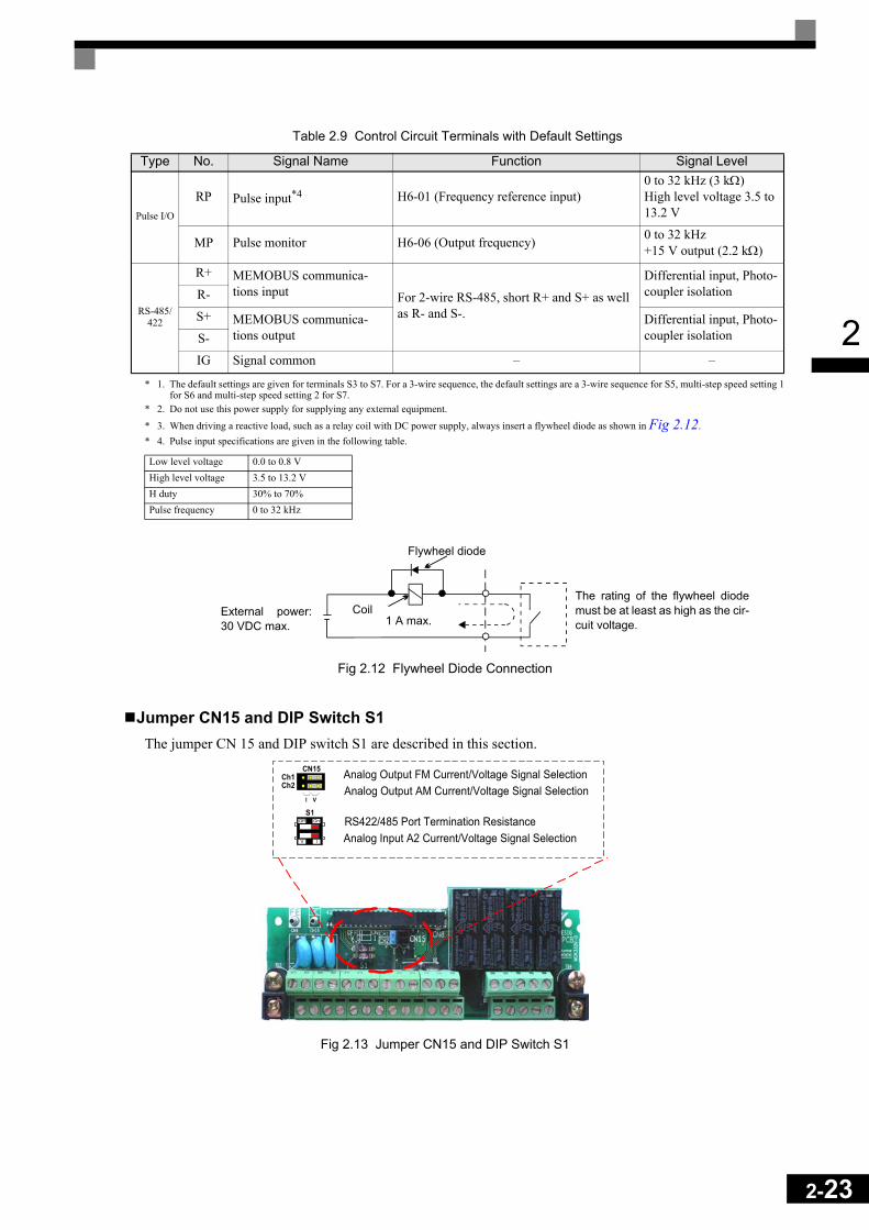
2
* 1. The default settings are given for terminals S3 to S7. For a 3-wire sequence, the default settings are a 3-wire sequence for S5, multi-step speed setting 1for S6 and multi-step speed setting 2 for S7.* 2. Do not use this power supply for supplying any external equipment.
* 3. When driving a reactive load, such as a relay coil with DC power supply, always insert a flywheel diode as shown in Fig 2.12.* 4. Pulse input specifications are given in the following table.
Fig 2.12 Flywheel Diode Connection
Jumper CN15 and DIP Switch S1The jumper CN 15 and DIP switch S1 are described in this section.
Fig 2.13 Jumper CN15 and DIP Switch S1
Pulse I/O
RP Pulse input*4 H6-01 (Frequency reference input)0 to 32 kHz (3 kΩ)High level voltage 3.5 to 13.2 V
MP Pulse monitor H6-06 (Output frequency) 0 to 32 kHz+15 V output (2.2 kΩ)
RS-485/422
R+ MEMOBUS communica-tions input For 2-wire RS-485, short R+ and S+ as well
as R- and S-.
Differential input, Photo-coupler isolationR-
S+ MEMOBUS communica-tions output
Differential input, Photo-coupler isolationS-
IG Signal common – –
Low level voltage 0.0 to 0.8 VHigh level voltage 3.5 to 13.2 VH duty 30% to 70%Pulse frequency 0 to 32 kHz
Table 2.9 Control Circuit Terminals with Default Settings
Type No. Signal Name Function Signal Level
External power:30 VDC max.
Coil
Flywheel diode
1 A max.
The rating of the flywheel diodemust be at least as high as the cir-cuit voltage.
S1
CN15Ch1Ch2
VI
Off On
V I
RS422/485 Port Termination ResistanceAnalog Input A2 Current/Voltage Signal Selection
Analog Output FM Current/Voltage Signal SelectionAnalog Output AM Current/Voltage Signal Selection
2-23

2-24
2
The functions of DIP switch S1 and jumper CN15 are shown in the following table.
Sinking/Sourcing ModeThe input terminal logic can be switched between sinking mode (0-V common) and sourcing mode (+24Vcommon) by using the terminals SN, SC, and SP. An external power supply is also supported, providing morefreedom in signal input methods.
Table 2.10 DIP Switch S1 and Jumper CN15 Settings
Name Function Setting
S1-1 RS-485 and RS-422 terminating resis-tance
OFF: No terminating resistanceON: Terminating resistance of 110 Ω
S1-2 Input method for analog input A2 V: 0 to 10 V (internal resistance: 20 kΩ)I: 4 to 20 mA (internal resistance: 250 Ω)
CN15-CH1
Multifunction analog output FM voltage/current switch
I: Current outputV: Voltage output
CN15-CH2
Multifunction analog output AM voltage/current switch
I: Current outputV: Voltage output
Table 2.11 Sinking/Sourcing Mode and Input Signals
Internal Power Supply – Sinking Mode External Power Supply – Sinking Mode
External +24V
Internal Power Supply – Sourcing Mode External Power Supply – Sourcing Mode
External +24V
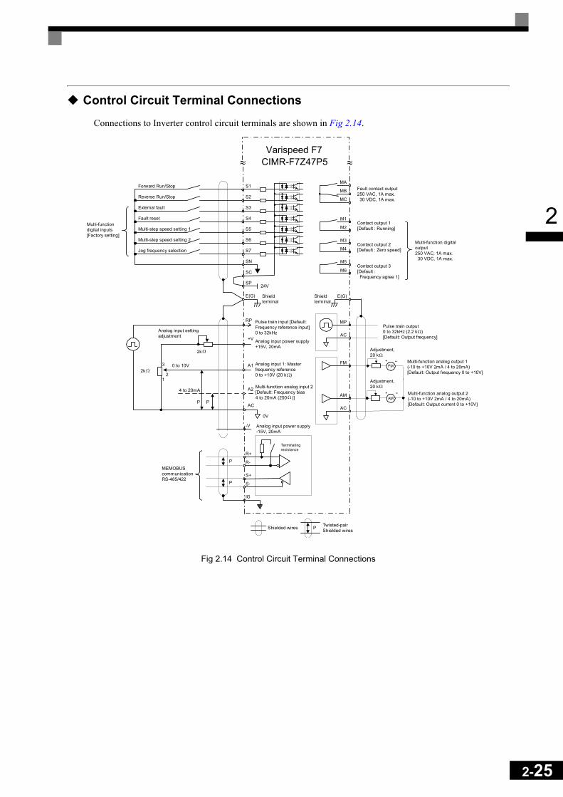
2
Control Circuit Terminal Connections
Connections to Inverter control circuit terminals are shown in Fig 2.14.
Fig 2.14 Control Circuit Terminal Connections
≈ ≈
M2
M1Contact output 1[Default : Running]
M4
M3Contact output 2[Default : Zero speed]
M6
M5Contact output 3[Default : Frequency agree 1]
MC
MB Fault contact output250 VAC, 1A max. 30 VDC, 1A max.
MA
Multi-function digitaloutput250 VAC, 1A max. 30 VDC, 1A max.
Forward Run/Stop S1
Reverse Run/Stop S2
S3External fault
S4Fault reset
S5Multi-step speed setting 1
S6
S7
SN
Multi-step speed setting 2
Jog frequency selection
SC
SP24V
Multi-functiondigital inputs[Factory setting]
+V
AC
A2 Multi-function analog input 2[Default: Frequency bias4 to 20mA (250 )]
Analog input 1: Masterfrequency reference0 to +10V (20 k )
A1
0V
RP
Analog input power supply+15V, 20mA
Pulse train input [Default:Frequency reference input]0 to 32kHz
Analog input power supply-15V, 20mA
-V
E(G) Shieldterminal
PP
4 to 20mA
0 to 10V3
2k
MP
E(G)
AC
Pulse train output0 to 32kHz (2.2 k )[Default: Output frequency]
FM+ -
AM+ -
AC
AM
FM
Adjustment,20 k
Multi-function analog output 1(-10 to +10V 2mA / 4 to 20mA)[Default: Output frequency 0 to +10V]
Multi-function analog output 2(-10 to +10V 2mA / 4 to 20mA)[Default: Output current 0 to +10V]
Shieldterminal
R+
R-
S+
S-
IG
Terminatingresistance
Shielded wires P Twisted-pairShielded wires
MEMOBUScommunicationRS-485/422
P
P
21
Analog input settingadjustment
Ω
2k Ω
Ω
Ω
Ω
Ω
Adjustment,20 k Ω
Varispeed F7CIMR-F7Z47P5
2-25

2-26
2
Control Circuit Wiring Precautions
Observe the following precautions when wiring control circuits. • Separate control circuit wiring from main circuit wiring (terminals R/L1, S/L2, T/L3, B1, B2, U/T1, V/T2,
W/T3, , 1, 2, and 3) and other high-power lines.• Separate wiring for control circuit terminals MA, MB, MC, M1, M2, M3, M4, M5, and M6 (contact out-
puts) from wiring to other control circuit terminals.• If using an optional external power supply, it shall be a UL Listed Class 2 power supply source.• Use twisted-pair or shielded twisted-pair cables for control circuits to prevent operating faults. • Ground the cable shields with the maximum contact area of the shield and ground.• Cable shields have to be grounded on both cable ends.

2
Wiring Check
Checks
Check all wiring after wiring has been completed. Do not perform continuity check on control circuits. Per-form the following checks on the wiring.
• Is all wiring correct?• Have no wire clippings, screws, or other foreign material been left?• Are all screws tight?• Are any wire ends contacting other terminals?
2-27

2-28
2
Installing and Wiring Option Cards
Option Card Models and Specifications
Up to two Option Cards can be mounted in the Inverter. You can mount one card into each of the two placeson the controller card (A, and C) like shown in Fig 2.15.
Table 2.12 lists the type of Option Cards and their specifications.
Installation
Before mounting an Option Card, remove the terminal cover and be sure that the charge indicator inside theInverter does not glow anymore. After that remove the Digital Operator and front cover and then mount theOption Card.
Refer to documentation provided with the Option Card for the mounting instructions for option slots A and C.
Table 2.12 Option Cards
Card Model Specifications MountingLocation
PG Speed Control CardsPG-B2 Two phase (phase A and B), +12V inputs, max.
response frequency: 50 kHz A
PG-X2 Three phase (phase A, B, Z), line driver inputs (RS422), max. response frequency: 300 kHz A
DeviceNet communications card
SI-N1/PDRT2 Option card for DeviceNet fieldbus C
Profibus-DP communications card SI-P1 Option card for Profibus-DP fieldbus C
InterBus-S communications card SI-R1 Option card for InterBus-S fieldbus C
CANOpencommunications card SI-S1 Option card for CANOpen fieldbus C
Analog Input Cards
AI-14U
2 channel high resolution analog input cardChannel 1: 0 to 10 V (20 kΩ)Channel 2: 4 to 20 mA (250 Ω)Resolution: 14 Bit
C
AI-14B
3 Channel high resolution analog input cardSignal level: -10 to +10 V (20 kΩ) 4 to 20 mA (250 Ω)Resolution: 13 Bit + sign
C
Digital Input CardsDI-08 8 bit digital speed reference input card C
DI-16H2 16 bit digital speed reference input card C

2
Preventing C Option Card Connectors from Rising After installing an Option Card into slot C, insert an Option Clip to prevent the side with the connector fromrising. The Option Clip can be easily removed by holding onto the protruding portion of the Clip and pulling itout.
Fig 2.15 Mounting Option Cards
A Option Card mounting spacer hole
CN4A Option Card connector
CN2C Option Card connector
A Option Card mounting spacer(Provided with A Option Card)
Option Clip(To prevent raising ofC Option Card)
A Option Card A Option Card mounting spacer
C Option Card mounting spacer
C Option Card
2-29

2-30
2
PG Speed Control Card Terminals and Specifications
PG-B2The terminal specifications for the PG-B2 are given in the following table.
PG-X2
The terminal specifications for the PG-X2 are given in the following table.
* 5 VDC and 12 VDC cannot be used at the same time.
Table 2.13 PG-B2 Terminal Specifications
Terminal No. Contents Specifications
TA1
1Power supply for pulse generator
12 VDC (±5%), 200 mA max.
2 0 VDC (GND for power supply)
3Pulse input terminals phase A
H: +8 to 12 V (max. input frequency: 50 kHz)
4 GND pulse input phase A
5Pulse input terminals phase B
H: +8 to 12 V (max. input frequency: 50 kHz)
6 GND pulse input phase B
TA2
1 Pulse monitor output terminals phase A Open collector output, 24 VDC, 30 mA max.
2
3 Pulse monitor output terminals phase B Open collector output, 24 VDC, 30 mA max.
4
TA3 (E) Shield connection terminal -
Table 2.14 PG-X2 Terminal Specifications
Terminal No. Contents Specifications
TA1
1
Power supply for pulse generator
12 VDC (±5%), 200 mA max.*
2 0 VDC (GND for power supply)
3 5 VDC (±5%), 200 mA max.*
4 Pulse input terminal phase A (+)
Line driver input (RS422 level)(maximum input frequency: 300 kHz)
5 Pulse input terminal phase A (–)
6 Pulse input terminal phase B (+)
7 Pulse input terminal phase B (–)
8 Pulse input terminal phase Z (+)
9 Pulse input terminal phase Z (–)
10 Common terminal inputs –
TA2
1 Pulse monitor output terminal phase A (+)
Line driver output (RS422 level output)
2 Pulse monitor output terminal phase A (–)
3 Pulse monitor output terminal phase B (+)
4 Pulse monitor output terminal phase B (–)
5 Pulse monitor output terminal phase Z (+)
6 Pulse monitor output terminal phase Z (–)
7 Common terminal monitor outputs –
TA3 (E) Shield connection terminal –

2
Wiring
Wiring the PG-B2 The following illustrations show wiring examples for the PG-B2 using the option cards power supply or anexternal power source for supplying the PG.
Fig 2.16 PG-B2 Wiring Using the Option Cards Power Supply
Fig 2.17 PG-B2 Wiring Using a 12 V External Power Supply
• Shielded twisted-pair wires must be used for signal lines.• Do not use the pulse generator's power supply for anything other than the pulse generator (encoder). Using
it for another purpose can cause malfunctions due to noise.• The length of the pulse generator's wiring must not be more than 100 meters.• The direction of rotation of the PG can be set in user parameter F1-05. The factory preset if for forward
rotation, A-phase advancement.
• When connecting to a voltage-output-type PG (encoder), select a PG that has an output impedance with acurrent of at least 12 mA to the input circuit photocoupler (diode).
• The pulse monitor dividing ratio can be changed using parameter F1-06.
Three-phase Inverter
Power supply +12 V
Power supply 0 Pulse input phase AGND pulse input phase A
Pulse input phase B
GND pulse input phase B
Pulse monitor output phase A
Pulse monitor output phase B
CN4CN4
R/L1
S/L2
T/L3
A-phase pulses
B-phase pulses
2-31
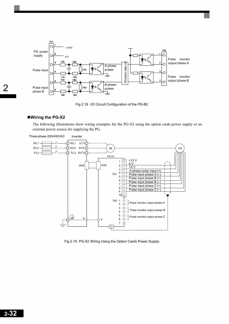
2-32
2
Fig 2.18 I/O Circuit Configuration of the PG-B2Wiring the PG-X2 The following illustrations show wiring examples for the PG-X2 using the option cards power supply or anexternal power source for supplying the PG.
Fig 2.19 PG-X2 Wiring Using the Option Cards Power Supply
PG powersupply
Pulse input
Pulse inputphase B
A-phasepulses
B-phasepulses
Div
isio
n ra
te c
ir-
Pulse monitoroutput phase B
Pulse monitoroutput phase A
Inverter
+5 VA-phase pulse input (+)Pulse input phase A (–)Pulse input phase B (+)Pulse input phase B (–)
Pulse monitor output phase A
Pulse monitor output phase B
Pulse monitor output phase Z
0 V
PG-X2
Three-phase 200/400VAC
Pulse input phase Z (+)Pulse input phase Z (–)
+12 V

2
Fig 2.20 PG-X2 Wiring Using a 5 V External Power Supply
• Shielded twisted-pair wires must be used for signal lines.• Do not use the pulse generator's power supply for anything other than the pulse generator (encoder). Using
it for another purpose can cause malfunctions due to noise.• The length of the pulse generator's wiring must not be more than 100 meters.• The direction of rotation of the PG can be set in user parameter F1-05 (PG Rotation). The factory preset if
for motor forward rotation, A-phase advancement.
Wiring Terminal Blocks
Do not use more cables longer than 100 meters for wiring the PG (encoder) and keep them separate frompower lines.
Use shielded, twisted-pair wires for pulse inputs and pulse output monitor wires, and connect the shield to theshield connection terminal.
Wire Sizes (Same for All Models)Terminal wire sizes are shown in Table 2.15.
Straight Solderless TerminalsWe recommend using straight solderless terminal on signal lines to simplify wiring and improve reliability.
Refer to Table 2.8 for specifications.
Table 2.15 Wire Sizes
Terminal Terminal Screws Wire Thickness (mm2) Wire Type
Pulse generator power supplyPulse input terminalPulse monitor output terminal
- Stranded wire: 0.5 to 1.25Single wire: 0.5 to 1.25
• Shielded, twisted-pair wire• Shielded, polyethylene-covered, vinyl
sheath cable(KPEV-S by Hitachi Electric Wire or equivalent)Shield connection terminal M3.5 0.5 to 2
TA1
IP12
IG
IP5
A (+)
A (-)
B (+)
B (-)
Z (+)
Z (-)
IG
TA3
PG-X2
1
2
3
4
5
6
7
8
9
10
AC
PG
+ +
+
-
-
0 V
Capacitor formomentarypower loss
0V +12V
PG powersupply
+12 V
+
-
2-33

2-34
2
Cable Lug Connector Sizes and Tightening TorqueThe lug sizes and tightening torques for various wire sizes are shown in Table 2.16.
PrecautionsThe wiring method is the same as the one used for straight solderless terminals. Refer to page 2-33. Observethe following precautions when wiring.
• Separate the control signal lines for the PG Speed Control Card from main power lines and other controlcircuits.
• The shield must be connected to prevent operational errors caused by noise. Also, do not use any lines thatare more than 100 m long.
• Connect the shield (green grounding cable of the option card) to the shield terminal (E).• Do not solder the ends of wires. Doing so may cause contact faults. • When not using straight solderless terminals, strip the wires to a length of approximately 5.5 mm• A separate power supply is required if the PG power supply consumption is higher than 200 mA. (If
momentary power loss must be handled, use a backup capacitor or other method.)• Make sure not to exceed the PG cards maximum input frequency. The output frequency of the pulse gener-
ator can be calculated using the following formula.
Table 2.16 Cable Lugs and Tightening Torque
Wire Thickness [mm2]Terminal Screws Crimp Terminal Size Tightening Torque (N • m)
0.5
M3.5
1.25 - 3.5
0.80.75 1.25 - 3.5
1.25 1.25 - 3.5
2 2 - 3.5
f PG (Hz) = Motor speed at maximum output frequency (min–1)60
x PG rating (p/rev)

3Digital Operator and
ModesThis chapter describes Digital Operator displays and functions, and pro-
vides an overview of operating modes and switching between modes.
Digital Operator and Modes ...................................................3-1 Modes ....................................................................................3-4
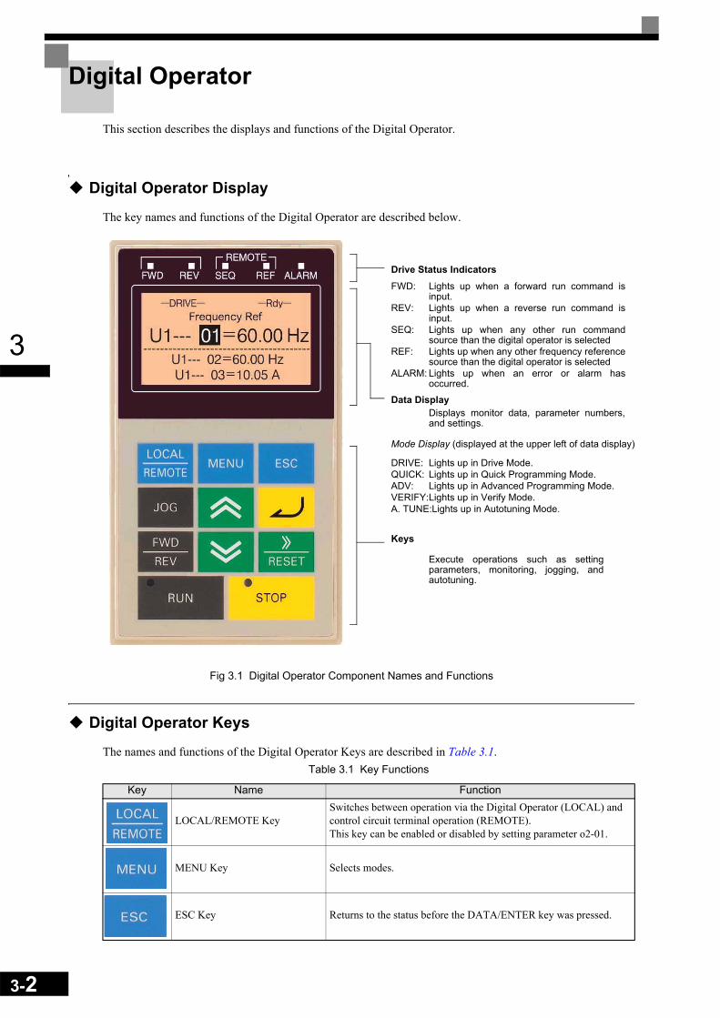
3-2
3
Digital Operator
This section describes the displays and functions of the Digital Operator.
Digital Operator Display
The key names and functions of the Digital Operator are described below.
Fig 3.1 Digital Operator Component Names and Functions
Digital Operator Keys
The names and functions of the Digital Operator Keys are described in Table 3.1.Table 3.1 Key Functions
Key Name Function
LOCAL/REMOTE KeySwitches between operation via the Digital Operator (LOCAL) and control circuit terminal operation (REMOTE).This key can be enabled or disabled by setting parameter o2-01.
MENU Key Selects modes.
ESC Key Returns to the status before the DATA/ENTER key was pressed.
Drive Status IndicatorsFWD: Lights up when a forward run command is
input.REV: Lights up when a reverse run command is
input.SEQ: Lights up when any other run command
source than the digital operator is selectedREF: Lights up when any other frequency reference
source than the digital operator is selectedALARM: Lights up when an error or alarm has
occurred.
Data DisplayDisplays monitor data, parameter numbers,and settings.
Mode Display (displayed at the upper left of data display)
DRIVE: Lights up in Drive Mode.QUICK: Lights up in Quick Programming Mode.ADV: Lights up in Advanced Programming Mode.VERIFY:Lights up in Verify Mode.A. TUNE:Lights up in Autotuning Mode.
Keys
Execute operations such as settingparameters, monitoring, jogging, andautotuning.
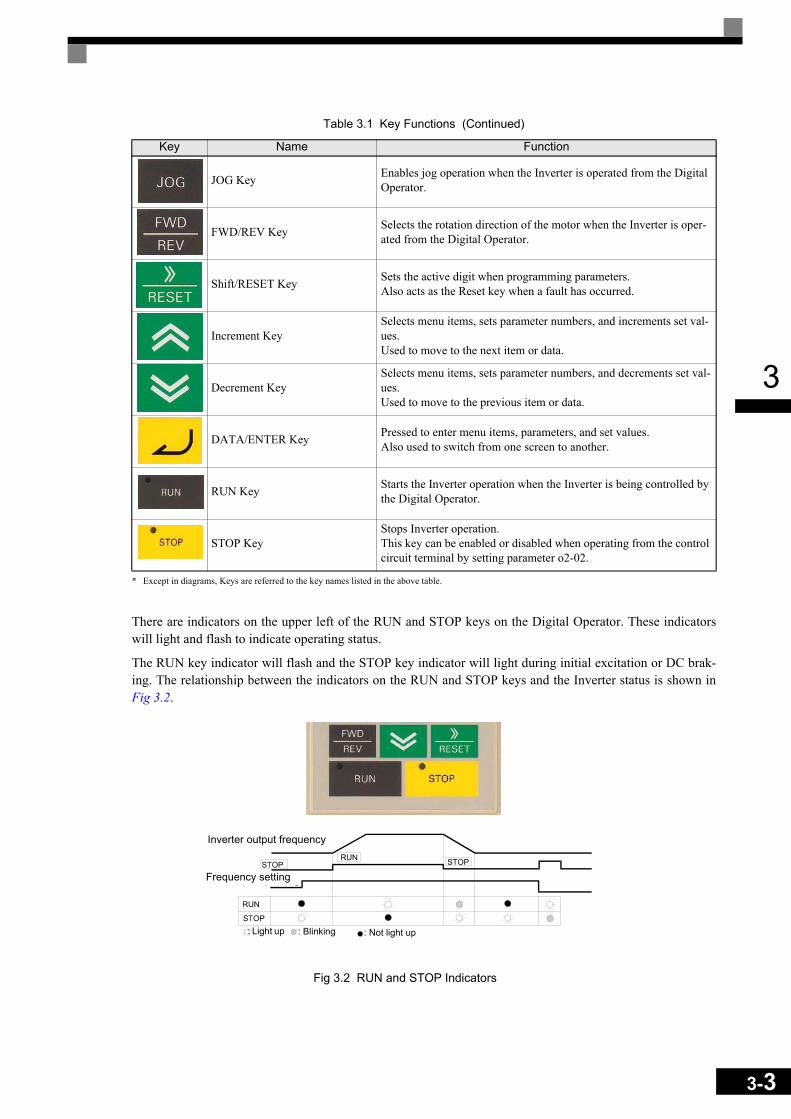
3
* Except in diagrams, Keys are referred to the key names listed in the above table.
There are indicators on the upper left of the RUN and STOP keys on the Digital Operator. These indicatorswill light and flash to indicate operating status.
The RUN key indicator will flash and the STOP key indicator will light during initial excitation or DC brak-ing. The relationship between the indicators on the RUN and STOP keys and the Inverter status is shown inFig 3.2.
Fig 3.2 RUN and STOP Indicators
JOG Key Enables jog operation when the Inverter is operated from the Digital Operator.
FWD/REV Key Selects the rotation direction of the motor when the Inverter is oper-ated from the Digital Operator.
Shift/RESET Key Sets the active digit when programming parameters.Also acts as the Reset key when a fault has occurred.
Increment KeySelects menu items, sets parameter numbers, and increments set val-ues. Used to move to the next item or data.
Decrement KeySelects menu items, sets parameter numbers, and decrements set val-ues. Used to move to the previous item or data.
DATA/ENTER Key Pressed to enter menu items, parameters, and set values.Also used to switch from one screen to another.
RUN Key Starts the Inverter operation when the Inverter is being controlled by the Digital Operator.
STOP KeyStops Inverter operation.This key can be enabled or disabled when operating from the control circuit terminal by setting parameter o2-02.
Table 3.1 Key Functions (Continued)
Key Name Function
Inverter output frequency
Frequency setting
: Light up : Blinking : Not light up
3-3

3-4
3
Modes
This section describes the Inverter's modes and switching between modes.
Inverter Modes
The Inverter's parameters and monitoring functions are organized in groups called modes that make it easier toread and set parameters.The Inverter is equipped with 5 modes.
The 5 modes and their primary functions are shown in the Table 3.2.
* Always perform autotuning with the motor before operating in the vector control modes.
Table 3.2 Modes
Mode Primary function(s)
Drive mode Use this mode to start/stop the inverter, to monitor values such as the frequency ref-erences or output current and for displaying fault information or the fault history.
Quick programming mode Use this mode to read and set the basic parameters.Advanced programming mode Use this mode to reference and set all parameters.
Verify mode Use this mode to read/set parameters that have been changed from their factory-set values.
Autotuning mode*Use this mode when running a motor with unknown motor data in the vector control modes. The motor data are measured/calculated and set automatically.This mode can also be used to measure only the motor line-to-line resistance.

3
Switching Modes
The mode selection display will appear when the MENU key is pressed. Press the MENU key from the modeselection display to switch through the modes in sequence.
Press the DATA/ENTER key to enter a mode and to switch from a monitor display to the setting display.
Fig 3.3 Mode Transitions
IMPORTANT
To run the inverter after viewing/changing parameters press the MENU key and the DATA/ENTER key in sequence to enter the Drive mode. A Run command is not accepted as long as the drive is in any other mode.
Frequency Ref-DRIVE-
U1-02=50.00HzU1-03=10.05A
** Main Menu **-DRIVE-
Operation
** Main Menu **-QUICK-
Quick Setting
** Main Menu **-ADV-
Programming
** Main Menu **-VERIFY-
Modified Consts
** Main Menu **-A.TUNE-
Auto-Tuning
Rdy
U1- 01=50.00Hz
Monitor-DRIVE-
U1-02=50.00HzU1-03=10.05A
Rdy
U1 - 01=50.00Hz
Control Method-QUICK-
A1-02=2
Initialization-ADV-
A1 - 00=1Select Language
None Modified
-VERIFY-
Frequency Ref-DRIVE-
U1-02=50.00HzU1-03=10.05A
U1- 01=50.00HzFrequency Ref
-DRIVE- Rdy
U1- 01=050.00Hz
Control Method-QUICK-
A1-02= 2Open Loop Vector
Select Language-ADV-
A1- 00 =0 *1*English
-ADV-Select Language
English
The constant number will be displayed if aconstant has been changed. Press theDATA/ENTER key to enable the change.
Monitor Display Setting DisplayMode SelectionDisplay
Display at Startup
Open Loop Vector
Tuning Mode Sel-A.TUNE-
Standard Tuning"0"
Tuning Mode Sel-A.TUNE-
Standard Tuning"0"
*2*
Rdy
A1- 00= 0 *1*
T1- 01=0 1 *0* T1- 01= 0 *0*
*2*
MENU
MENU
MENU
MENU
MENU
RESET
RESET
ESC ESC ESC
ESC ESC
ESC ESC ESC
ESC
ESC ESC
(0.00 ~ 50.00)" 00.00Hz "
3-5
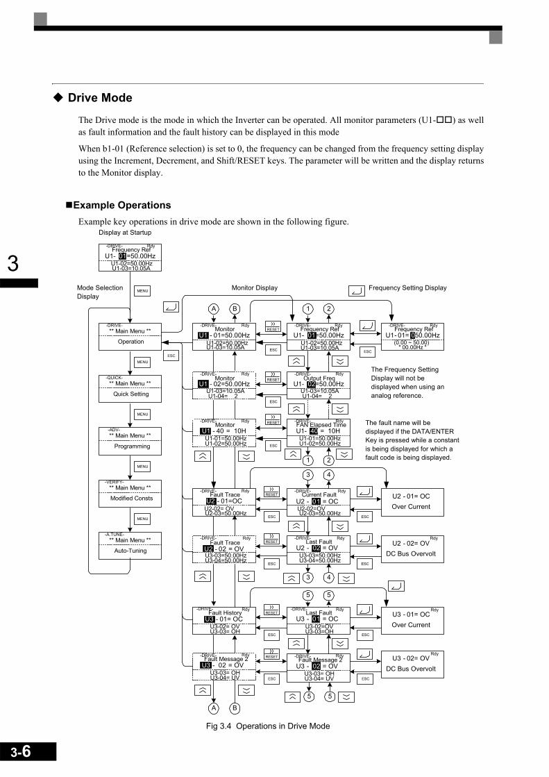
3-6
3
Drive Mode
The Drive mode is the mode in which the Inverter can be operated. All monitor parameters (U1- ) as wellas fault information and the fault history can be displayed in this mode
When b1-01 (Reference selection) is set to 0, the frequency can be changed from the frequency setting displayusing the Increment, Decrement, and Shift/RESET keys. The parameter will be written and the display returnsto the Monitor display.
Example Operations Example key operations in drive mode are shown in the following figure.
Fig 3.4 Operations in Drive Mode
Frequency Ref-DRIVE-
U1-02=50.00HzU1-03=10.05A
** Main Menu **-DRIVE-
Operation
** Main Menu **-QUICK-
Quick Setting
** Main Menu **-ADV-
Programming
** Main Menu **-VERIFY-
Modified Consts
** Main Menu **-A.TUNE-
Auto-Tuning
U1- 01=50.00Hz
Monitor-DRIVE-
U1-02=50.00HzU1-03=10.05A
U1 - 01=50.00HzFrequency Ref
-DRIVE-
U1-02=50.00HzU1-03=10.05A
U1- 01=50.00HzFrequency Ref
-DRIVE-
U1 - 01= 050.00Hz
Monitor Display Frequency Setting DisplayMode SelectionDisplay
Display at Startup
Fault Trace-DRIVE-
U2-02= OVU2-03=50.00Hz
U2 - 01=OC
Fault History-DRIVE-
U3-02= OVU3-03= OH
U3 - 01= OC
Output Freq-DRIVE-
U1-04= 2U1-03=10.05A
U1- 02=50.00Hz
FAN Elapsed Time-DRIVE-
U1-01=50.00HzU1-02=50.00Hz
U1- 40 = 10H
1 2
1 2
Last Fault-DRIVE-
U3-02=OVU3-03=OH
U3 - 01 = OC
Fault Message 2-DRIVE-
U3-03= OHU3-04= UV
U3 - 02 = OV
5 5
5 5
A B
A B
Current Fault-DRIVE-
U2-02=OVU2-03=50.00Hz
U2 - 01 = OC
Last Fault-DRIVE-
U3-03=50.00HzU3-04=50.00Hz
U2 - 02 = OV
3 4
3 4
U2 - 01= OC
U2 - 02= OV
Over Current
DC Bus Overvolt
U3 - 01= OCOver Current
U3 - 02= OVDC Bus Overvolt
The fault name will bedisplayed if the DATA/ENTERKey is pressed while a constantis being displayed for which afault code is being displayed.
Rdy
Rdy
Rdy
Rdy
Rdy
Rdy
Rdy
Rdy
Rdy Rdy
Rdy
Rdy
The Frequency SettingDisplay will not bedisplayed when using ananalog reference.
Monitor-DRIVE-
U1-04= 2U1-03=10.05A
U1 - 02=50.00HzRdy
Monitor-DRIVE-
U1-01=50.00HzU1-02=50.00Hz
U1 - 40 = 10HRdy
Rdy
Rdy
Rdy
Fault Trace-DRIVE-
U3-03=50.00HzU3-04=50.00Hz
U2 - 02 = OV
Rdy
Fault Message 2-DRIVE-
U3-03= OHU3-04= UV
U3 - 02 = OV
Rdy
MENU
RESET
ESC
MENU
ESCESC
MENU
MENU
MENU
RESET
RESET
RESET
RESET
RESET
RESET
ESC
ESC
ESC ESC
ESC ESC
ESC ESC
ESC ESC
(0.00 ~ 50.00)" 00.00Hz "

3
Note: 1. When changing the display with the Increment / Decrement keys, the next display after the one for the last parameter number will be the one for the first parameter number and vice versa. For example, the next display after the one for U1-01 will be U1-40. This is indicated in the figures by the let-ters A and B and the numbers 1 to 6.
2. The display for the first monitor parameter (frequency reference) will be displayed when power is turned ON. The monitor item displayed at startup can be set in o1-02 (Monitor Selection after Power Up).Operation cannot be started from the mode selection display.
Quick Programming Mode
In quick programming mode, the basic parameters required for Inverter trial operation can be monitored andset.
The parameters can be changed from the setting displays. Use the Increment, Decrement, and Shift/RESETkeys to change the frequency. The parameter will be written and the monitor display will be returned to whenthe DATA/ENTER key is pressed after changing the setting.
Refer to Chapter 5 User Parameters for details on the parameters displayed in quick programming mode.
Example Operations Example key operations in quick programming mode are shown in the following figure.
Fig 3.5 Operations in Quick Programming Mode
** Main Menu **-DRIVE-
Operation
** Main Menu **-QUICK-
Quick Setting
** Main Menu **-ADV-
Programming
** Main Menu **-VERIFY-
Modified Consts
** Main Menu **-A.TUNE-
Auto-Tuning
Control Method-QUICK-
A1-02=2 *2*Open Loop Vector
Reference Source-QUICK-
b1-01=1 *1*Terminals
Run Source-QUICK-
b1-02=1 *1*Terminals
Monitor Display Setting DisplayMode Selection Display
MOL Fault Select-QUICK-
L1-01=1 *1*Std Fan Cooled
StallP Decel Sel-QUICK-
L3-04=1 *1*Enabled
Terminal AM Gain-QUICK-
H4-05 = 50%
A B
A B
Control Method-QUICK-
A1-02= 2 *2*Open Loop Vector
Reference Source-QUICK-
b1-01= 1 *1*Terminals
Run Source-QUICK-
b1-02= 1 *1*Terminals
Terminal AM Gain-QUICK-
H4-05 = 0050.0%
MOL Fault Select-QUICK-
L1-01= 1 *1*Std Fan Cooled
StallP Decel Sel-QUICK-
L3-04= 1 *1*Enabled
MENU
MENU
MENU
MENU
MENU
ESC ESC
ESC
ESC
ESC
ESC
ESC
(0.0 ~ 1000.0)50.0%
(0.0 ~ 1000.0)50.0%
3-7
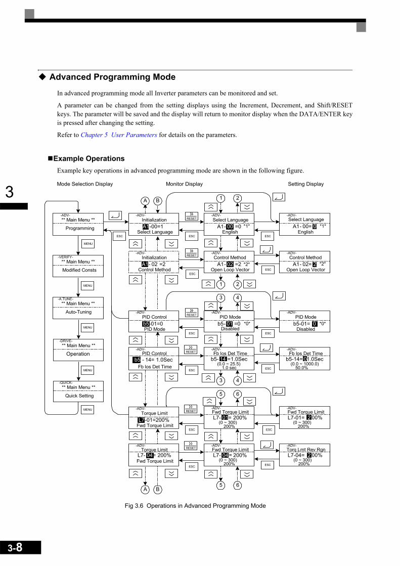
3-8
3
Advanced Programming Mode
In advanced programming mode all Inverter parameters can be monitored and set.
A parameter can be changed from the setting displays using the Increment, Decrement, and Shift/RESETkeys. The parameter will be saved and the display will return to monitor display when the DATA/ENTER keyis pressed after changing the setting.
Refer to Chapter 5 User Parameters for details on the parameters.
Example Operations Example key operations in advanced programming mode are shown in the following figure.
Fig 3.6 Operations in Advanced Programming Mode
A1- 00= 0
** Main Menu **-DRIVE-
Operation
** Main Menu **-QUICK-
Quick Setting
** Main Menu **-ADV-
Programming
** Main Menu **-VERIFY-
Modified Consts
** Main Menu **-A.TUNE-
Auto-Tuning
Initialization-ADV-
A1-00=1Select Language
Select Language-ADV-
A1- 00 =0English
-ADV-Select Language
English*1*
Monitor Display Setting DisplayMode Selection Display
PID Control-ADV-
b5-01=0PID Mode
Control Method-ADV-
A1- 02 =2Open Loop Vector
PID Mode-ADV-
b5- 01 =0Disabled
Control Method-ADV-
A1- 02= 2Open Loop Vector
*2*
*1*
*2*
1 2
1 2
PID Mode-ADV-
b5-01= 0Disabled
*0* *0*
Fb los Det Time-ADV-
b5- 14 =1.0SecFb los Det Time
-ADV-
b5-14= 01.0Sec
3 4
3 4
Torque Limit-ADV-
L7-01=200%Fwd Torque Limit
5 6
5 6
Fwd Torque Limit-ADV-
L7- 01= 200%Fwd Torque Limit-ADV-
L7-01= 2 00%
Torq Lmt Rev Rgn-ADV-
L7-04= 2 00%Fwd Torque Limit-ADV-
L7- 04= 200%
A B
A B
Initialization-ADV-
A1- 02 =2Control Method
PID Control-ADV-
b5 - 14= 1.0SecFb los Det Time
Fwd Torque Limit
-ADV-
L7- 04= 200%Torque Limit
ESC
MENU
MENU
MENU
MENU
MENU
ESC
ESC
ESC
ESC
ESCESC
ESC ESC
ESC ESC
ESC ESC
RESET
RESET
RESET
RESET
RESET
RESET
(0.0 ~ 25.5)1.0 sec
(0.0 ~ 1000.0)50.0%
(0 ~ 300)200%
(0 ~ 300)200%
(0 ~ 300)200%
(0 ~ 300)200%

3
Setting ParametersHere the procedure to change C1-01 (Acceleration Time 1) from 10 s to 20 s is shown.
Table 3.3 Setting Parameters in Advanced Programming Mode
Step No. Digital Operator Display Description
1 Power supply turned ON.
2
Press the MENU key 3 times to enter the advanced programming mode.3
4
5 Press the DATA/ENTER to access the monitor display.
6 Press the Increment or Decrement key to display the parameter C1-01 (Acceleration Time 1).
7 Press the DATA/ENTER key to access the setting display. The cur-rent setting value of C1-01 is displayed.
8 Press the Shift/RESET key to move the flashing digit to the right.
9 Press the Increment key to change set value to 20.00 s.
10 Press the DATA/ENTER key to save the set data.
11 “Entry Accepted” is displayed for 1 sec after pressing the DATA/ENTER key.
12 The display returns to the monitor display for C1-01.
Frequency Ref-DRIVE-
U1-02=50.00HzU1-03=10.05A
Rdy
U1- 01=50.00Hz
** Main Menu **-DRIVE-
Operation
** Main Menu **-QUICK-
Quick Setting
** Main Menu **-ADV-
Programming
Initialization-ADV-
A1-00=1Select Language
Accel / Decel-ADV-
Accel Time 1C1-00 = 10.0sec
Accel Time 1-ADV-
C1-01 = 0 010.0sec(0.0 ~ 6000.0)
"10.0 sec"
Accel Time 1-ADV-
C1-01 = 00 10.0sec(0.0 ~ 6000.0)
"10.0 sec"
0
Accel Time 1-ADV-
C1-01 = 001 0.0sec(0.0 ~ 6000.0)
"10.0 sec"
1
Accel Time 1-ADV-
C1-01 = 001 0.0sec(0.0 ~ 6000.0)
"10.0 sec"
2
Entry Accepted-ADV-
Accel Time 1-ADV-
C1-01 = 20.0sec(0.0 ~ 6000.0)
"10.0 sec"
01
3-9
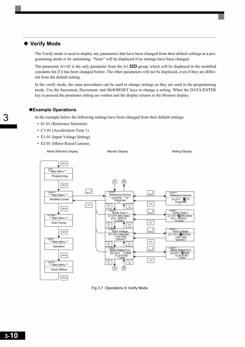
3-10
3
Verify Mode
The Verify mode is used to display any parameters that have been changed from their default settings in a pro-gramming mode or by autotuning. “None” will be displayed if no settings have been changed.
The parameter A1-02 is the only parameter from the A1- group, which will be displayed in the modifiedconstants list if it has been changed before. The other parameters will not be displayed, even if they are differ-ent from the default setting.
In the verify mode, the same procedures can be used to change settings as they are used in the programmingmode. Use the Increment, Decrement, and Shift/RESET keys to change a setting. When the DATA/ENTERkey is pressed the parameter setting are written and the display returns to the Monitor display.
Example OperationsIn the example below the following settings have been changed from their default settings:
• b1-01 (Reference Selection)• C1-01 (Acceleration Time 1)• E1-01 (Input Voltage Setting)• E2-01 (Motor Rated Current).
Fig 3.7 Operations in Verify Mode
** Main Menu **-DRIVE-
Operation
** Main Menu **-QUICK-
Quick Setting
** Main Menu **-ADV-
Programming
** Main Menu **-VERIFY-
Modified Consts
** Main Menu **-A.TUNE-
Auto-Tuning
Monitor Display Setting DisplayMode Selection Display
Reference Source-VERIFY-
b1-01=0 *0*Terminals
ESC
Accel Time 1-VERIFY-
C1-01=200.0sec
A B
A B
Reference Source-VERIFY-
b1-01= 0 *0*Terminals
Input Voltage-VERIFY-
E1-01=190VAC
Motor Rated FLA-VERIFY-
E2-01= 2.00AMotor Rated FLA
-VERIFY-
E2-01= 2.00A
Input Voltage-VERIFY-
E1-01= 190VAC
Accel Time 1-VERIFY-
C1-01= 0200.0sec
"1""1"
MENU
ESC
MENU
MENU
MENU
MENU
MENU
ESC
ESC
ESC
(0.0 ~ 6000.0)"10.0sec"
(0.0 ~ 6000.0)"10.0sec"
(155~255)"200VAC"
(155~255)"200VAC"
(0.32~6.40)"1.90A"
(0.32~6.40)"1.90A"
3
Autotuning Mode
Autotuning automatically measures and sets the required motor data in order to achieve the maximum perfor-mance. Always perform autotuning before starting operation when using the vector control modes.
When V/f control has been selected, only stationary autotuning for line-to-line resistance can be selected.
When the motor cannot be disconnected from the load, and Open Loop or Closed Loop Vector Control shallbe used perform stationary autotuning.
Example of OperationEnter the motor rated output power (in kW), rated voltage, rated current, rated frequency, rated speed andnumber of poles specified on the nameplate of the motor and then press the RUN key. The motor is automati-cally run and the measured motor data are set in the E2- parameters.
Always set the above items. Otherwise autotuning cannot be started, e.g. it cannot be started from the motorrated voltage input display.
A parameter can be changed from the setting displays using the Increment, Decrement, and Shift/RESETkeys. The parameter will be saved when the DATA/ENTER key is pressed.
3-11

3-12
3
The following example shows the autotuning input procedure for standard rotating autotuning in Open LoopVector Control.
Fig 3.8 Operation in Autotuning Mode
If a fault occurs during autotuning, refer to Chapter 7 Troubleshooting.
START GOAL
** Main Menu **-DRIVE-
Operation
** Main Menu **-QUICK-
Quick Setting
** Main Menu **-ADV-
Programming
** Main Menu **-VERIFY-
Modified Consts
** Main Menu **-A.TUNE-
Auto-Tuning
Monitor Display Setting DisplayMode Selection Display
Tuning Mode Sel-A.TUNE-
T1- 01 =0 *0*
Auto-Tuning-A.TUNE-
Press RUN keyTuning Ready ?
Tune Proceeding-A.TUNE-
40.0Hz/10.5A
Standard Tuning
Tuning Mode Sel-A.TUNE-
01 = 0*0*
Rated Frequency-A.TUNE-
T1- 05 = 50.0Hz
Rated Speed-A.TUNE-
T1- 07 = 1750RPM
Rated Frequency-A.TUNE-
T1-05 = 050.0Hz
Rated Speed-A.TUNE-
Rdy
Tune Aborted-A.TUNE-
STOP key
The display willautomaticallychange dependingon the status ofautotuning.
Standard Tuning
START GOAL
Tune Proceeding-A.TUNE-
40.0Hz/10.5A
Tune Successful-A.TUNE-
Tune Successful
Tune Proceeding-A.TUNE-
"0" "0"
0.0Hz/0.0A
MENU
ESC
MENU
MENU
MENU
MENU
MENU
ESC
ESC
ESC
RUN
STOP
(0.0~400.0)"50.0Hz"
(0.0~400.0)"50.0Hz"
(0~24000)"1750"
Mtr Rated Power-A.TUNE-
T1- 02= 0.40kWMtr Rated Power
-A.TUNE-
T1-01= 0 00.40kW"0.40kW"
ESC
Rated Voltage-A.TUNE-
T1- 03 = 200.0VACRated Voltage
-A.TUNE-
ESC
Rated Current-A.TUNE-
Rated Current-A.TUNE-
ESC
(0.00~650.00)"0.40kW"
(0.00~650.00)
"200.0VAC"(0.0~255.0)
"200.0VAC"(0.0~255.0)
T1- 03 = 200.0VAC
T1- 04 = 1.90A"1.90A"
(0.32~6.40) T1- 04 = 001.90A
"1.90A"(0.32~6.40)
Number of Poles-A.TUNE-
T1- 06 = 4Number of Poles
-A.TUNE-
T1-06 = 4(2~48)
"4"(2~48)
"4"
T1- 07 = 01750RPM(0~24000)
"1750"
4Trial Operation
This chapter describes the procedures for trial operation of the Inverter and provides an example of trial operation.
Trial Operation Procedure......................................................4-2
Trial Operation .......................................................................4-3
Adjustment Suggestions ......................................................4-14
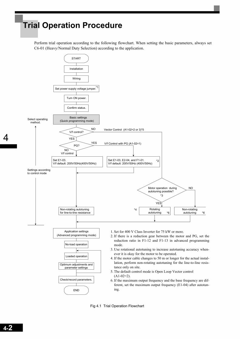
4-2
4
Trial Operation Procedure
Perform trial operation according to the following flowchart. When setting the basic parameters, always setC6-01 (Heavy/Normal Duty Selection) according to the application.
Fig 4.1 Trial Operation Flowchart
V/f Control with PG (A1-02=1)
START
Installation
Wiring
Turn ON power.
Confirm status.
Basic settings(Quick programming mode)
Set power supply voltage jumper.
Select operatingmethod.
Settings accordingto control mode
Application settings(Advanced programming mode)
No-load operation
Loaded operation
Optimum adjustments andparameter settings
Check/record parameters.
END
YES
V/f control
Vector Control (A1-02=2 or 3)*5
Set E1-03.V/f default: 200V/50Hz(400V/50Hz)
Set E1-03, E2-04, and F1-01.V/f default: 200V/50Hz (400V/50Hz)
YES
NO
V/f control?
PG?
Motor operation duringautotuning possible?
Non-rotating autotuningfor line-to-line resistance
Rotatingautotuning
Non-rotatingautotuning
*3
*4
*2
*1
*6 *6
NO
NO
YES
1. Set for 400 V Class Inverter for 75 kW or more.2. If there is a reduction gear between the motor and PG, set the
reduction ratio in F1-12 and F1-13 in advanced programmingmode.
3. Use rotational autotuning to increase autotuning accuracy when-ever it is okay for the motor to be operated.
4. If the motor cable changes to 50 m or longer for the actual instal-lation, perform non-rotating autotuning for the line-to-line resis-tance only on site.
5. The default control mode is Open Loop Vector control (A1-02=2).
6. If the maximum output frequency and the base frequency are dif-ferent, set the maximum output frequency (E1-04) after autotun-ing.

4
Trial Operation
Application Confirmation
For applications with quadratic torque characteristic like pumps, fans or blowers set C6-01 (Heavy/NormalDuty selection) to 1 or 2 (Normal Duty 1 or 2). Select the Normal Duty mode (1 or 2) regarding the requiredoverload capability.
For applications with constant torque characteristics like conveyors etc. always set C6-01 to 0 (Heavy Duty).The default setting is of C6-01 is 0 (Heavy Duty).
For details on the Heavy/Normal Duty selection refer to Chapter 6 Application and Overload Selections.
Setting the Power Supply Voltage Jumper (400 V Class Inverters of 75 kW or Higher)
The power supply voltage jumper must be set for 400 V Class Inverters of 75 kW or higher. Insert the jumperinto the voltage connector nearest to the actual power supply voltage.
The jumper is factory-set to 440 V. If the power supply voltage is not 440 V, use the following procedure tochange the setting.1. Turn OFF the power supply and wait for at least 5 minutes.2. Confirm that the CHARGE indicator has gone out.3. Remove the terminal cover.4. Insert the jumper at the position for the voltage supplied to the Inverter (see Fig 4.2).5. Return the terminal cover to its original position.
Fig 4.2 Large-capacity Inverter Connections
Connector
Jumper (factory-set position)
CHARGE indicator
200 V class power supply400V class power supply
Power supply input terminals
4-3

4-4
4
Power ON
Confirm all of the following items and then turn ON the power supply.• Check that the power supply is of the correct voltage.
200 V class: 3-phase 200 to 240 VDC, 50/60 Hz400 V class: 3-phase 380 to 480 VDC, 50/60 Hz
• Make sure that the motor output terminals (U, V, W) and the motor are connected correctly.• Make sure that the Inverter control circuit terminal and the control device are wired correctly.• Set all Inverter control circuit terminals to OFF.• When using a PG Speed Control Card, make sure that it is wired correctly.
Checking the Display Status
After normal power up without any problems the operator display shows the following:
When a fault has occurred, the details of the fault will be displayed instead of the above display. In that case,refer to Chapter 7 Troubleshooting. The following display shows an example of a display for faulty opera-tion.
Display for normal operation The frequency reference monitor is dis-played in the data display section.
Display for fault operationThe display will differ depending on the type of fault.A low voltage alarm is shown at left.
Frequency Ref-DRIVE-
U1-02=50.00HzU1-03=10.05A
Rdy
U1- 01=50.00Hz
-DRIVE-UV
DC Bus Undervolt

4
Basic Settings
Switch to the quick programming mode (“QUICK” will be displayed on the LCD screen) and set the follow-ing parameters.
Refer to Chapter 3 Digital Operator and Modes for Digital Operator operating procedures and to Chapter 5User Parameters and Chapter 6 Parameter Settings by Function for details on the parameters.
Table 4.1 Basic Parameter Settings
: Must be set. : Set as required.
ClassParame-ter Num-
berName Description Setting
RangeFactory Setting Page
A1-02 Control method selection
Sets the control method for the Inverter.0: V/f control1: V/f control with PG2: Open Loop Vector control3: Closed Loop Vector Control
0 to 3 0 5-7
b1-01 Reference selec-tion
Sets the frequency reference input method.0: Digital Operator1: Control circuit terminal
(analog input)2: MEMOBUS communications3: Option Card4: Pulse train input
0 to 4 1
5-96-76-646-82
b1-02 Operation method selection
Sets the run command input method.0: Digital Operator1: Control circuit terminal (digital input)2: MEMOBUS communications3: Option Card
0 to 3 1
5-96-126-646-82
b1-03 Stopping method selection
Selects stopping method when stop com-mand is sent.0: Deceleration to stop1: Coast to stop2: DC braking stop 3: Coast to stop with timer
0 to 3 0 5-96-14
C1-01 Acceleration time 1
Sets the acceleration time in seconds for the output frequency to climb from 0% to 100%.
0.0 to 6000.0 10.0 s 5-196-19
C1-02 Deceleration time 1
Sets the deceleration time in seconds for the output frequency to fall from 100% to 0%.
0.0 to 6000.0 10.0 s 5-196-19
C6-01 Heavy /Normal Duty selection
Set to Heavy Duty or Normal Duty regarding to the applications require-ments.0: Heavy Duty1: Normal Duty 12: Normal Duty 2
0 or 2 0 5-246-2
C6-02 Carrier frequency selection
Sets the carrier frequency. The factory setting and setting range depends on the setting of C6-01.
0 to FDepends on setting of C6-01.
5-24
d1-01 to d1-16 and
d1-17
Frequency refer-ences 1 to 16 and jog frequency ref-erence
Sets the required speed references for multi-step speed operation or jogging.
0 to 150.00 Hz*
d1-01 to d1-16: 0.00
Hzd1-17: 6.00
Hz
5-256-10
4-5

4-6
4
* The setting range is valid if Heavy Duty is selected (C6-01=0, default setting). If Normal Duty 1 or 2 is selected (C6-01=1 or 2) the setting range will be 0.0 to 400.0 Hz.
E1-01 Input voltage set-ting
Sets the Inverter's nominal input voltage in volts.
155 to 255 V (200 V class)310 to 510 V (400 V class)
200 V(200 V class)400 V(400 V class)
5-306-110
E2-01 Motor rated cur-rent Sets the motor rated current.
10% to 200% of Inverter's rated current
Setting for general-purpose motor of
same capacity as
Inverter
5-316-486-108
H4-02 and
H4-05
FM and AM ter-minal output gain
Can be used to adjust the analog output when an instrument is connected to the FM or AM terminal.
0.0 to 1000.0%
H4-02: 100%
H4-05: 50%
5-47
L1-01 Motor protection selection
Used to enable or disable the motor over-load protection function.0: Disabled1: Protection for general purpose motor (fan cooled)2: Protection for frequency converter motor (externally cooled)3: Protection for special vector control motor
0 to 3 1 5-506-48
L3-04Stall prevention selection during deceleration
If using the dynamic brake option (brak-ing resistor, Braking Resistor Units and Braking Units), be sure to set parameter L3-04 to 0 (disabled) or 3 (enabled with braking resistor).
0 to 3 1 5-536-24
Table 4.1 Basic Parameter Settings (Continued)
: Must be set. : Set as required.
ClassParame-ter Num-
berName Description Setting
RangeFactory Setting Page

4
Settings for the Control Methods
The usable Autotuning methods depend on the control method setting of the Inverter.
Overview of SettingsMake the required settings in quick programming mode and autotuning mode according to Fig 4.1.
Setting the Control MethodSelect the appropriate control mode as required by the application. Table 4.2 shows the main properties ofeach control mode.
Note With Open Loop or Closed Loop Vector control, the motor and Inverter must be connected 1:1. The motor capacity for which stable control is possible is 50% to 100% of the Inverters capacity.
V/f Control without PG (A1-02 = 0)• Set either one a fixed V/f pattern (E1-03=0 to E) or specify a user-set V/f pattern (E1-03=F) as required for
the motor and load characteristics using E1-04 to E1-13 in advanced programming mode.
• Perform non-rotating autotuning for the line-to-line resistance if the motor cable is 50 m or longer for theactual installation or if a heavy load causes motor stalling. Refer to the following section on Autotuning fordetails on non-rotating autotuning.
V/f Control with PG (A1-02=1)Additionally to the V/f control without PG settings the following settings have to be made:
• Set the number of motor poles in E2-04 (Number of Motor Poles)• Set the number of pulses per rotation in F1-01 (PG Constant). If there is a reduction gear between the
motor and PG, set the reduction ratio in F1-12 and F1-13 in advanced programming mode.
Table 4.2 Control Mode Properties
Control Mode Parameter Set-ting Basic Control Main Applications
V/f control A1-02 = 0 Fixed voltage/frequency ratio control
Variable speed control, particularly control of multiple motors with one Inverter and replacing existing inverters
V/f control with PG A1-02 = 1 Fixed voltage/frequency ratio control with speed compensation using a PG
Applications requiring high-precision speed control using a PG on the machine side
Open Loop Vector control
A1-02 = 2(factory setting) Current vector control without a PG Variable speed control, applications
requiring speed and torque accuracy.
Closed Loop Vector control A1-02 = 3 Closed Loop Vector control
Very high-performance control with a PG (simple servo drives, high-preci-sion speed control, torque control, and torque limiting)
Simple operation of a general-purpose motor at 50 Hz:
E1-03 = 0 or F (default)If E1-03 = F, the default setting in the user setting from E1-04 to E1-13 are for 00 Hz
Simple operation of a general-purpose motor at 60 Hz: E1-03 = 1
4-7
4-8
4
Open Loop Vector Control (A1-02 = 2)Always perform autotuning. If the motor can be operated, perform rotating autotuning. If the motor cannot beoperated, perform non-rotating autotuning. Refer to the following section on Autotuning for details on auto-tuning.
Closed Loop Vector Control (A1-02=3)Always perform autotuning. If the motor can be operated, perform rotating autotuning. If the motor cannot beoperated, perform non-rotating autotuning. Refer to the following section on Autotuning for details on auto-tuning.
Autotuning
Autotuning sets motor parameters automatically when using Open Loop or Closed Loop Vector control, whenthe cable length is long or the installation has changed.
Setting the Autotuning ModeOne of the following three autotuning modes can be set.
• Rotating autotuning• Non-rotating autotuning• Non-rotating autotuning for line-to-line resistance only
Rotating Autotuning (T1-01 = 0)Rotating autotuning is used for Open Loop and Closed Loop Vector control only. Set T1-01 to 0, input thedata from the motor nameplate, and then press the RUN key on the Digital Operator. The Inverter will operatethe motor for approximately 1 minute and set the required motor parameters automatically.
Non-rotating Autotuning (T1-01 = 1)Non-rotating autotuning is used for Open Loop and Closed Loop Vector control only. Set T1-01 to 1, input thedata from the motor nameplate, and then press the RUN key on the Digital Operator. The inverter will supplypower to the non-rotating motor for approximately 1 minute and some of the motor parameters will be setautomatically. The remaining motor parameters will be set automatically during the first time operation.
Non-rotating Autotuning for Line-to-Line Resistance (T1-01 = 2)Non-rotating autotuning for line-to-line resistance can be used in any control mode. This is the only possibleautotuning for V/f control and V/f control with PG.
It can be used to improve the performance when the motor cable is long, the cable length has changed or whenthe motor and inverter have different capacities.
To perform autotuning in V/f control or V/f control with PG, set T1-02 (Motor rated power) and T1-04 (Motorrated current) and then press the RUN key on the Digital Operator. The Inverter will supply power to the non-rotating motor for approximately 20 seconds and the Motor line-to-line resistance and cable resistance will beautomatically measured.

4
Precautions Before Using AutotuningRead the following precautions before using autotuning.
• Autotuning an Inverter is fundamentally different from autotuning a servo system. Inverter autotuningautomatically adjusts parameters according to detected motor data, whereas servo system autotuningadjusts parameters according to the detected size of the load.
• When speed precision or torque precision is required at high speeds (i.e., 90% of the rated speed or higher),use a motor with a rated voltage that is ~20 V less than the input power supply voltage of the Inverter for200 V-class Inverters and ~40 V less for 400 V-class Inverters. If the rated voltage of the motor is the sameas the input power supply voltage, the voltage output from the Inverter will be unstable at high speeds andsufficient performance will not be possible.
• Use non-rotating autotuning whenever the load cannot be disconnected from the motor.• Use rotating autotuning whenever performing autotuning when high precision is required or for a motor
that is not connected to a load.• If rotating autotuning is performed for a motor connected to a load, the motor data will not be found accu-
rately and the might be poor. Never perform rotating autotuning for a motor connected to a load.• If the wiring between the Inverter and motor changes by 50 m or more perform non-rotating autotuning for
line-to-line resistance.• If the motor cable is long (50 m or longer), perform non-rotating autotuning for line-to-line resistance.• If a mechanical brake is used, make sure that it is not opened for non-rotating autotuning. Make sure that it
is opened for rotating autotuning.• Power will be supplied to the motor when non-rotating autotuning is performed even though the motor will
not turn. Do not touch the motor until autotuning has been completed.
• The status of the multi-function inputs and multi-function outputs during autotuning will be as shown inthe following table.
• To cancel autotuning, press the STOP key on the Digital Operator.
Tuning Mode Multi-function Inputs Multi-function Outputs
Rotating autotuning Do not work Same as during normal operation
Non-rotating autotuning Do not work Maintain same status as when autotuning is started.
Non-rotating autotuning for line-to-line resistance Do not work Maintain same status as
when autotuning is started.
4-9

4-10
4
Precautions for Rotating and Non-rotating Autotuning• If the motor rated voltage is higher than the power supply voltage, lower the base voltage value like shown
in Fig 4.3 to prevent saturation of the Inverter’s output voltage. Use the following procedure to performautotuning.
1. Input the voltage of the input power supply to T1-03 (Motor rated voltage).
2. Input the results of the following formula to T1-05 (Motor base frequency):
3. Perform autotuning.
After the completing autotuning, set E1-04 (Max. output frequency) to the base frequency from the motor’snameplate.
Fig 4.3 Motor Base Frequency and Inverter Input Voltage Setting
• When speed precision is required at high speeds (i.e., 90% of the rated speed or higher), set T1-03 (Motorrated voltage) to the input power supply voltage × 0.9. In this case at high speeds the output current willincrease as the input power supply voltage is reduced. Be sure to provide sufficient margin in the Invertercurrent.
Precautions after Rotating and Non-rotating AutotuningIf the maximum output frequency and base frequency are different, set the maximum output frequency (E1-04) after autotuning.
T1-05 Base frequency from motor nameplate T1-03Motor rated voltage-----------------------------------------------×=
0 Output frequencyBase frequencyfrom motor nameplate
T1-03
Rated voltagefrom motorname plate
Output voltage
Base frequency frommotor name plate x T1-03
Rated voltage from motorname plate

4
Parameter Settings for AutotuningThe following parameters must be set before autotuning.
* 1. Displayed only, when a motor switch command is set for a multi-function digital input (one of H1-01 to H1-05 set to 16).* 2. Only setting 2 (non-rotating autotuning for line-to-line resistance only) is possible for V/f control or V/f control with PG.* 3. Stable vector control will be possible when the setting is between 50% and 100%.* 4. For an inverter motor or vector control motor, the voltage and frequency may be lower than for a general-purpose motor. Always confirm setting on the
nameplate or in test reports. Also, if you know the no-load values, set the no-load voltage in T1-03 and the no-load frequency in T1-05 to obtain better accuracy.
* 5. The setting range is valid if Heavy Duty is selected (C6-01=0, default setting). If Normal Duty 1 or 2 is selected (C6-01=1 or 2) the setting range will be 0.0 to 400.0 Hz.
Table 4.3 Parameter Settings before Autotuning
Parame-ter Num-
ber
NameDisplay Setting
RangeFactory Setting
Data Displays during Autotuning
Display V/f V/f with PG
Open Loop
Vector
Closed Loop
Vector
T1-00*1
Motor 1/2 selection
Set the location where the auto-tuned motor data are to be stored.1: E1 to E2 (motor 1)2: E3 to E4 (motor 2)
1 or 2 1 Yes Yes Yes YesSelect Motor
T1-01
Autotuning mode selec-tion
Set the autotuning mode.0: Rotating autotuning1: Non-rotating autotuning2: Non-rotating autotuning for
line-to-line resistance only
0 to 2
2 (V/f and V/f with
PG)0 (Open
Loop Vec-tor)*2
Yes(only
2)
Yes(only
2)Yes Yes
Tuning Mode Sel
T1-02
Motor rated power Set the output power of the
motor in Kilowatts.
10% to 200% of Inverter
rated output *3
Same as Inverter
rated out-put
Yes Yes Yes YesMtr Rated Power
T1-03
Motor rated voltage
Set the rated voltage of the motor.*4
0 to 255.0 V (200 V class)0 to 510.0 V (400 V class)
200.0 V (200 V class)
400.0 V (400 V class)
– – Yes YesRated Voltage
T1-04
Motor rated current
Set the rated current of the motor in Amps.
10% to 200% of Inverter
rated current*3
Same as general-purpose
motor with same
capacity as Inverter
Yes Yes Yes YesRated Current
T1-05
Motor rated frequency Set the base frequency of the
motor.*40 to 150.0 Hz
*550.0 Hz – – Yes Yes
Rated Frequency
T1-06
Number of motor poles
Set the number of motor poles. 2 to 48 poles 4 poles – – Yes YesNumber of poles
T1-07
Motor rated speed Set the base speed of the motor
in r/min. 0 to 24000 1750r/min – – Yes Yes
Rated Speed
T1-08
Number of PG pulses per revolu-tion
Sets the number of pulses for the PG (pulse generator or encoder) per motor revolution without a multiplication factor
0 to 60000 1024 - Yes - Yes
PG Pulses/Rev
4-11
4-12
4
Application Settings
Parameters can be set as required in advanced programming mode (i.e. “ADV” is displayed on the LCDscreen). All the parameters which can be set in quick programming mode are also displayed and can be set inthe advanced programming mode.
Setting Examples• The following points are examples of settings for applications.• When using an Inverter-mounted braking resistor (ERF), set L8-01 to 1 to enable ERF braking resistor
overheating protection. • To prevent the machine from being operated in reverse, set b1-04 to 1 to disable reverse operation.• To increase the speed of a 50 Hz motor by 10%, set E1-04 to 55.0 Hz.• To use a 0 to 10 V analog signal for a 50 Hz motor for variable-speed operation between 0 and 45 Hz (0%
to 90% speed deduction), set H3-02 to 90.0%.• To limit the speed range between 20% and 80% set d2-01 to 80.0% and set d2-02 to 20.0%.
No-load Operation
This section describes trial operation in which the motor is in no-load state, that means the machine is not con-nected to the motor. To avoid failures caused by the wiring of the control circuit it is recommended to use theLOCAL mode. Press the LOCAL/REMOTE key on the Digital Operator to change to LOCAL mode (the SEQand REF indicators on the Digital Operator should be OFF).
Always confirm safety around the motor and machine before starting Inverter operation from the DigitalOperator. Confirm that the motor works normally and that no errors are displayed at the Inverter. For applica-tions, at which the machine can be driven in one direction only, check the motor rotation direction.
Operation with Jog frequency reference (d1-17, default: 6.00 Hz) can be started and stopped by pressing andreleasing the JOG key on the Digital Operator. If the external control circuit prevents operation from the Dig-ital Operator, confirm that emergency stop circuits and machine safety mechanisms are functioning, and thenstart operation in REMOTE mode (i.e., with a signal from the control signal terminal). The safety precautionsmust always be taken before starting the inverter and the motor connected.
Loaded Operation
Connecting the Load• After confirming that the motor has stopped completely, connect the mechanical system.• Be sure to tighten all the screws when connecting the motor shaft to the mechanical system.
NOTE
Both, a RUN command (forward or reverse) and a frequency reference (or multi-step speed command) must be provided to start Inverter operation.

4
Operation using the Digital Operator• Use the Digital Operator to start operation in LOCAL mode in the same way as in no-load operation.• If fault occurs during operation, make sure that the STOP key on the Digital Operator is accessible easily.• At first, set the frequency reference to a low speed, e.g. to one tenth of the normal operating speed.
Checking Operating Status• Having checked that the operating direction is correct and that the machine is operating smoothly at slow
speed, increase the frequency reference.• After changing the frequency reference or the rotation direction, check that there is no oscillation or abnor-
mal sound from the motor. Check the monitor display to ensure that U1-03 (Output Current) is not toohigh.
• Refer to Table 4.4 if hunting, vibration, or other problems originated by the control system occur.
Check and Recording Parameters
Use the verify mode (“VERIFY” is displayed on the LCD screen) to check parameters that have been changedfor trial operation and record them in a parameter table.
Any parameters that have been changed by autotuning will also be displayed in the verify mode.
If required, the copy function in parameters o3-01 and o3-02 displayed in advanced programming mode canbe used to copy the changed settings from the inverter to a recording area in the Digital Operator. If changedsettings are saved in the Digital Operator, they can be easily copied back to the Inverter to speed up systemrecovery if for any reason the inverter has to be replaced.
The following functions can also be used to manage parameters.• Saving user initial parameter values• Setting access levels for parameters• Setting a password
Saving User Initial Parameter Values (o2-03)• If o2-03 is set to 1 after completing trial operation, the settings of parameters will be saved in a separate
memory area in the inverter. When the Inverter settings have been changed for any reason, the parameterscan be initialized to the settings saved in the separate memory area by setting A1-03 (Initialize) to 1110.
Parameter Access Levels (A1-01)• A1-01 can be set to 0 (monitoring-only) to prevent parameters from being changed. A1-01 can also be set
to 1 (User-specified Parameters) to display only parameters required by the machine or application in aprogramming mode. These parameters can be determined by setting the A2-XX parameters.
Password (A1-04 and A1-05)• When the access level is set to monitoring-only (A1-01 = 0), a password can be set so that parameters will
be displayed only when the correct password has been input.
4-13

4-14
4
Adjustment Suggestions
If hunting, vibration, or other problems originated in the control system occur during trial operation, adjust theparameters listed in the following table according to the control method. This table lists the most commonlyused parameters only.
Table 4.4 Adjusted Parameters
Control Method
Name (Parameter Number) Influence Factory
Setting
Recom-mended Setting
Adjustment Method
V/f control(A1-02 = 0 or 1)
Hunting-prevention gain (N1-02)
Controlling hunting and vibration in mid-dle-range speeds (10 to 40 Hz)
1.00 0.50 to 2.00
• Reduce the setting if torque is insufficient for heavy loads.
• Increase the setting if hunt-ing or vibration occurs for light loads.
Carrier frequency selection (C6-02)
• Reducing motor magnetic noise
• Controlling hunting and vibration at low speeds
Depends on capac-ity
0 to default
• Increase the setting if motor magnetic noise is high.
• Reduce the setting if hunt-ing or vibration occurs at low to middle-range speeds.
Torque compensation primary delay time constant (C4-02)
• Increasing torque and speed response
• Controlling hunting and vibration
Depends on capac-ity
200 to 1000 ms
• Reduce the setting if torque or speed response is low.
• Increase the setting if hunt-ing or vibration occurs.
Torque compensation gain (C4-01)
• Improving torque at low speeds (10 Hz or lower)
• Controlling hunting and vibration
1.00 0.50 to 1.50
• Increase the setting if torque is insufficient at low speeds.
• Reduce the setting if hunt-ing or vibration occurs for light loads.
Middle output fre-quency voltage (E1-08)Minimum output fre-quency voltage (E1-10)
• Improving torque at low speeds
• Controlling shock at startup
Depends on capac-ity and voltage
Default to Default + 5 V*
• Increase the setting if torque is insufficient at low speeds.
• Reduce the setting if the shock at startup is large.
Open Loop Vector con-trol (A1-02 = 2)
Speed feedback detec-tion control (AFR) gain(N2-01)
• Increasing torque and speed response
• Controlling hunting and vibration in mid-dle-range speeds (10 to 40 Hz)
1.00 0.50 to 2.00
• Reduce the setting if torque or speed response is low.
• Increase the setting if hunt-ing or vibration occurs.
Torque compensation primary delay time constant (C4-02)
• Increasing torque and speed response
• Controlling hunting and vibration
20 ms 20 to 100 ms
• Reduce the setting if torque or speed response is low.
• Increase the setting if hunt-ing or vibration occurs.
Slip compensation pri-mary delay time (C3-02)
• Increasing speed response
• Improving speed sta-bility
200 ms 100 to 500 ms
• Reduce the setting if speed response is low.
• Increase the setting if the speed is not stable.
Slip compensation gain (C3-01)
• Improving speed accuracy 1.0 0.5 to 1.5
• Increase the setting if speed response is low.
• Reduce the setting if the speed is too high.
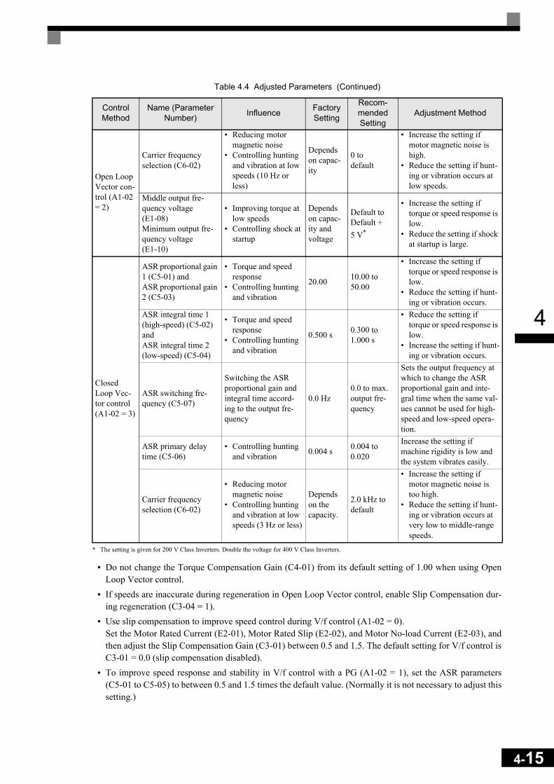
4
* The setting is given for 200 V Class Inverters. Double the voltage for 400 V Class Inverters.
• Do not change the Torque Compensation Gain (C4-01) from its default setting of 1.00 when using OpenLoop Vector control.
• If speeds are inaccurate during regeneration in Open Loop Vector control, enable Slip Compensation dur-ing regeneration (C3-04 = 1).
• Use slip compensation to improve speed control during V/f control (A1-02 = 0).Set the Motor Rated Current (E2-01), Motor Rated Slip (E2-02), and Motor No-load Current (E2-03), andthen adjust the Slip Compensation Gain (C3-01) between 0.5 and 1.5. The default setting for V/f control isC3-01 = 0.0 (slip compensation disabled).
• To improve speed response and stability in V/f control with a PG (A1-02 = 1), set the ASR parameters(C5-01 to C5-05) to between 0.5 and 1.5 times the default value. (Normally it is not necessary to adjust thissetting.)
Open Loop Vector con-trol (A1-02 = 2)
Carrier frequency selection (C6-02)
• Reducing motor magnetic noise
• Controlling hunting and vibration at low speeds (10 Hz or less)
Depends on capac-ity
0 to default
• Increase the setting if motor magnetic noise is high.
• Reduce the setting if hunt-ing or vibration occurs at low speeds.
Middle output fre-quency voltage (E1-08)Minimum output fre-quency voltage (E1-10)
• Improving torque at low speeds
• Controlling shock at startup
Depends on capac-ity and voltage
Default to Default + 5 V*
• Increase the setting if torque or speed response is low.
• Reduce the setting if shock at startup is large.
Closed Loop Vec-tor control (A1-02 = 3)
ASR proportional gain 1 (C5-01) and ASR proportional gain 2 (C5-03)
• Torque and speed response
• Controlling hunting and vibration
20.00 10.00 to 50.00
• Increase the setting if torque or speed response is low.
• Reduce the setting if hunt-ing or vibration occurs.
ASR integral time 1 (high-speed) (C5-02) and ASR integral time 2 (low-speed) (C5-04)
• Torque and speed response
• Controlling hunting and vibration
0.500 s 0.300 to 1.000 s
• Reduce the setting if torque or speed response is low.
• Increase the setting if hunt-ing or vibration occurs.
ASR switching fre-quency (C5-07)
Switching the ASR proportional gain and integral time accord-ing to the output fre-quency
0.0 Hz0.0 to max. output fre-quency
Sets the output frequency at which to change the ASR proportional gain and inte-gral time when the same val-ues cannot be used for high-speed and low-speed opera-tion.
ASR primary delay time (C5-06)
• Controlling hunting and vibration 0.004 s 0.004 to
0.020
Increase the setting if machine rigidity is low and the system vibrates easily.
Carrier frequency selection (C6-02)
• Reducing motor magnetic noise
• Controlling hunting and vibration at low speeds (3 Hz or less)
Depends on the capacity.
2.0 kHz to default
• Increase the setting if motor magnetic noise is too high.
• Reduce the setting if hunt-ing or vibration occurs at very low to middle-range speeds.
Table 4.4 Adjusted Parameters (Continued)
Control Method
Name (Parameter Number) Influence Factory
Setting
Recom-mended Setting
Adjustment Method
4-15
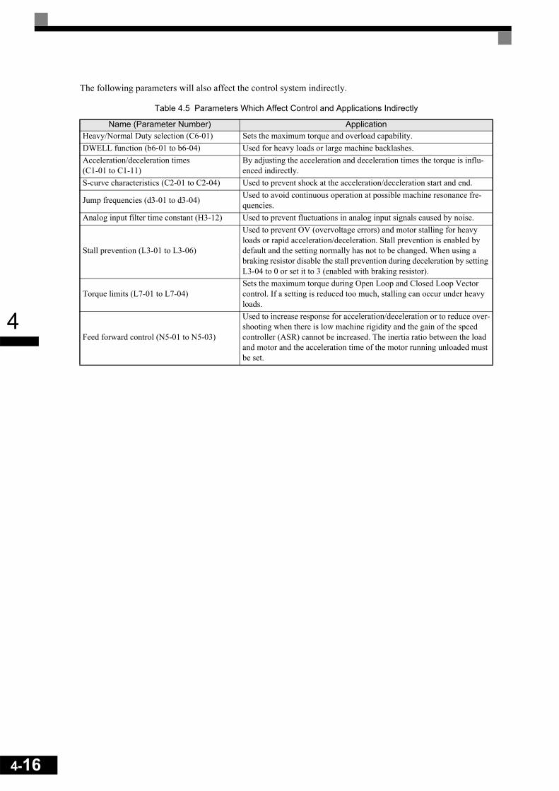
4-16
4
The following parameters will also affect the control system indirectly.
Table 4.5 Parameters Which Affect Control and Applications Indirectly
Name (Parameter Number) ApplicationHeavy/Normal Duty selection (C6-01) Sets the maximum torque and overload capability.DWELL function (b6-01 to b6-04) Used for heavy loads or large machine backlashes.Acceleration/deceleration times (C1-01 to C1-11)
By adjusting the acceleration and deceleration times the torque is influ-enced indirectly.
S-curve characteristics (C2-01 to C2-04) Used to prevent shock at the acceleration/deceleration start and end.
Jump frequencies (d3-01 to d3-04) Used to avoid continuous operation at possible machine resonance fre-quencies.
Analog input filter time constant (H3-12) Used to prevent fluctuations in analog input signals caused by noise.
Stall prevention (L3-01 to L3-06)
Used to prevent OV (overvoltage errors) and motor stalling for heavy loads or rapid acceleration/deceleration. Stall prevention is enabled by default and the setting normally has not to be changed. When using a braking resistor disable the stall prevention during deceleration by setting L3-04 to 0 or set it to 3 (enabled with braking resistor).
Torque limits (L7-01 to L7-04)Sets the maximum torque during Open Loop and Closed Loop Vector control. If a setting is reduced too much, stalling can occur under heavy loads.
Feed forward control (N5-01 to N5-03)
Used to increase response for acceleration/deceleration or to reduce over-shooting when there is low machine rigidity and the gain of the speed controller (ASR) cannot be increased. The inertia ratio between the load and motor and the acceleration time of the motor running unloaded must be set.

5 User Parameters
This chapter describes all user parameters that can be set in the Inverter.
User Parameter Descriptions.................................................5-2
Digital Operation Display Functions and Levels ....................5-3
User Parameter Tables..........................................................5-7

5-2
5
User Parameter Descriptions
This section describes the contents of the user parameter tables.
Description of User Parameter Tables
User parameter tables are structured as shown below. Here, b1-01 (Frequency Reference Selection) is used asan example.
Param-eter
Num-ber
NameDescription Setting
RangeFactory Setting
Change during Opera-
tion
Control MethodsMEMO-
BUS Register
PageV/f
V/f with PG
Open Loop
Vector
Closed Loop
VectorDisplay
b1-01 Reference selection
Sets the frequency reference input method.0: Digital Operator1: Control circuit terminal
(analog input)2: MEMOBUS communica-
tions3: Option Card4: Pulse train input
0 to 4 1 No Q Q Q Q 180H -
• Parameter Number: The number of the user parameter.• Name: The name of the user parameter.• Description: Details on the function or settings of the user parameter.• Setting Range: The setting range for the user parameter.
• Factory Setting:
The factory setting (each control method has its own factory setting. Therefore the factory setting changes when the control method is changed.)Refer to page page 5-70, Factory Settings that Change with the Con-trol Method (A1-02) for factory settings that are changed by setting the control method.
• Change during Operation: Indicates whether the parameter can be changed or not while the Inverter is in operation.Yes: Changes are possible during operation.No: Changes are not possible during operation.
• Control Methods: Indicates the control methods in which the user parameter can be monitored or set.
Q: The item can be monitored and set as well in quick program-ming mode as in advanced programming mode.
A: The item can be monitored and set in advanced programming mode only.
No: The item cannot be monitored or set in this control method.• MEMOBUS Register: The register number used for MEMOBUS communications.• Page: Reference page for more detailed information about the parameter.

5
Digital Operation Display Functions and Levels
The following figure shows the Digital Operator display hierarchy for the Inverter.
MENU Drive Mode
Inverter can be operated and its status can be displayed.
Quick Programming Mode
Minimum parameters required for operation can be monitored or set.
Advanced Programming Mode
All parameters can be moni-tored or set.
Verify Mode
Parameters changed from the default settings can be moni-tored or set.
Autotuning Mode
Automatically sets motor parameters for open-loop vec-tor control or measures the line-to-line resistance for V/f con-trol.
No. Function Page
U1 Status Monitor Parameters 5-64U2 Fault Trace 5-65U3 Fault History 5-68
A1 Initialize Mode 5-7A2 User-specified Setting Mode 5-8b1 Operation Mode Selections 5-9b2 DC Injection Braking 5-10b3 Speed Search 5-11b4 Timer Function 5-12b5 PID Control 5-13b6 Dwell Functions 5-16b7 Droop Control 5-16b8 Energy Saving 5-17b9 Zero Servo Control 5-18C1 Acceleration/Deceleration 5-19C2 S-curve Acceleration/Deceleration 5-20C3 Motor Slip Compensation 5-20C4 Torque Compensation 5-22C5 Speed Control (ASR) 5-23C6 Carrier Frequency 5-24d1 Preset Reference 5-25d2 Reference Limits 5-26d3 Jump Frequencies 5-27d4 Reference Frequency Hold 5-27d5 Torque Control 5-28d6 Field Weakening 5-29E1 V/f Pattern 5-30E2 Motor Setup 5-31E3 Motor 2 V/f Pattern 5-33E4 Motor 2 Setup 5-34F1 PG Option Setup 5-35F2 Analog Reference Card 5-37F3 Digital Reference Card 5-38F6 Serial Communications Settings 5-40H1 Multi-function Digital Inputs 5-41H2 Multi-function Digital Outputs 5-43H3 Multi-function Analog Inputs 5-45H4 Multi-function Analog Outputs 5-47H5 MEMOBUS Communications 5-48H6 Pulse Train Input/Output 5-49L1 Motor Overload 5-50L2 Power Loss Ride through 5-51L3 Stall Prevention 5-52L4 Reference Detection 5-54L5 Fault Restart 5-54L6 Torque Detection 5-55L7 Torque Limits 5-56L8 Hardware Protection 5-57N1 Hunting Prevention Function 5-58N2 Automatic Frequency Regulator 5-59N3 High-slip Braking 5-59o1 Monitor Selection 5-60o2 Digital Operator Functions 5-61o3 Copy Function 5-62
T Motor Autotuning 5-63
5-3

5-4
5
User Parameters Available in Quick Programming Mode
The minimum user parameters required for Inverter operation can be monitored and set in quick programmingmode. The user parameters displayed in quick programming mode are listed in the following table. These, andall other user parameters, are also displayed in advanced programming mode.
Param-eter
Num-ber
NameDescription Setting
RangeFactory Setting
Change during Opera-
tion
Control Methods MEMOBUS
Regis-ter
V/fV/f
with PG
Open Loop
Vector
Closed Loop
VectorDisplay
A1-02
Control method selection
Sets the control method for the Inverter.0: V/f control1: V/f control with PG2: Open-Loop Vector control3: Closed Loop Vector control
0 to 3 2 No Q Q Q Q 102HControl Method
b1-01
Reference source selec-tion
Sets the frequency reference input method.0: Digital Operator1: Control circuit terminal (analog
input)2: MEMOBUS communications3: Option Card4: Pulse train input
0 to 4 1 No Q Q Q Q 180HReference Source
b1-02
RUN source selection
Sets the run command input method0: Digital Operator1: Control circuit terminal (digital multi
function inputs)2: MEMOBUS communications3: Option Card
0 to 3 1 No Q Q Q Q 181HRun Source
b1-03
Stopping method selection
Select stopping method when stop com-mand is input.0: Deceleration to stop1: Coast to stop2: DC braking stop (Stops faster than
coast to stop, without regenerative operation.)
3: Coast to stop with timer (Run commands are disregarded during deceleration time.)
0 to 3 0 No Q Q Q Q 182HStopping Method
C1-01
Accelera-tion time 1 Sets the acceleration time to accelerate
from 0 Hz to the maximum output fre-quency. 0.0 to
6000.0 *1
10.0 s Yes Q Q Q Q
200HAccel Time 1
C1-02
Decelera-tion time 1 Sets the deceleration time to decelerate
from the maximum output frequency to 0 Hz.
201HDecel Time 1
C6-01
Heavy/Nor-mal Duty selection
0: Heavy Duty 1: Normal Duty 12: Normal Duty 2
0 or 2 0 No Q Q Q Q 223HHeavy/Nor-mal Duty
C6-02
Carrier fre-quency selection
Selects the carrier frequency.Select F to enable detailed settings using parameters C6-03 to C6-05.
0 to F 1 No Q Q Q Q 224HCarrier Freq Sel
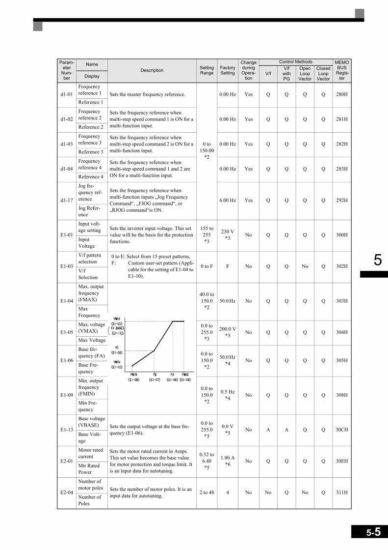
5
d1-01Frequency reference 1 Sets the master frequency reference.
0 to 150.00
*2
0.00 Hz Yes Q Q Q Q 280HReference 1
d1-02Frequency reference 2
Sets the frequency reference when multi-step speed command 1 is ON for a multi-function input.
0.00 Hz Yes Q Q Q Q 281HReference 2
d1-03Frequency reference 3
Sets the frequency reference when multi-step speed command 2 is ON for a multi-function input.
0.00 Hz Yes Q Q Q Q 282HReference 3
d1-04Frequency reference 4
Sets the frequency reference when multi-step speed command 1 and 2 are ON for a multi-function input.
0.00 Hz Yes Q Q Q Q 283HReference 4
d1-17
Jog fre-quency ref-erence
Sets the frequency reference when multi-function inputs „Jog Frequency Command“, „FJOG command“, or „RJOG command“is ON.
6.00 Hz Yes Q Q Q Q 292HJog Refer-ence
E1-01
Input volt-age setting Sets the inverter input voltage. This set
value will be the basis for the protection functions.
155 to 255*3
230 V*3 No Q Q Q Q 300H
Input Voltage
E1-03
V/f pattern selection
0 to E: Select from 15 preset patterns.F: Custom user-set pattern (Appli-
cable for the setting of E1-04 to E1-10).
0 to F F No Q Q No Q 302HV/f Selection
E1-04
Max. output frequency (FMAX)
40.0 to 150.0
*250.0 Hz No Q Q Q Q 303H
Max Frequency
E1-05Max. voltage (VMAX)
0.0 to 255.0
*3
200.0 V*3 No Q Q Q Q 304H
Max Voltage
E1-06
Base fre-quency (FA) 0.0 to
150.0*2
50.0 Hz *4 No Q Q Q Q 305H
Base Fre-quency
E1-09
Min. output frequency (FMIN)
0.0 to 150.0
*2
0.5 Hz*4 No Q Q Q Q 308H
Min Fre-quency
E1-13
Base voltage(VBASE) Sets the output voltage at the base fre-
quency (E1-06).
0.0 to 255.0
*3
0.0 V*5 No A A Q Q 30CH
Base Volt-age
E2-01
Motor rated current
Sets the motor rated current in Amps.This set value becomes the base value for motor protection and torque limit. It is an input data for autotuning.
0.32 to 6.40*5
1.90 A*6 No Q Q Q Q 30EH
Mtr Rated Power
E2-04
Number of motor poles Sets the number of motor poles. It is an
input data for autotuning. 2 to 48 4 No No Q No Q 311HNumber of Poles
Param-eter
Num-ber
NameDescription Setting
RangeFactory Setting
Change during Opera-
tion
Control Methods MEMOBUS
Regis-ter
V/fV/f with PG
Open Loop
Vector
Closed Loop
VectorDisplay
5-5
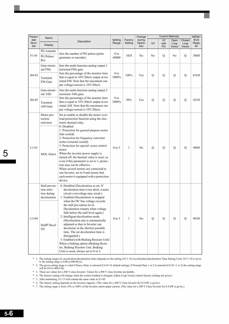
5-6
5
* 1. The setting ranges for acceleration/deceleration times depends on the setting of C1-10 (Acceleration/deceleration Time Setting Unit). If C1-10 is set to 0, the setting range is 0.00 to 600.00 (s).
* 2. The given setting range is valid if Heavy Duty is selected (C6-01=0, default setting). If Normal Duty 1 or 2 is selected (C6-01=1 or 2) the setting range will be 0.0 to 400.0 Hz.
* 3. These are values for a 200 V class Inverter. Values for a 400 V class Inverter are double.* 4. The factory setting will change when the control method is changed. (Open Loop Vector control factory settings are given.)* 5. After autotuning, E1-13 will contain the same value as E1-05.* 6. The factory setting depends on the Inverter capacity. (The value for a 200 V Class Inverter for 0.4 kW is given.)* 7. The setting range is from 10% to 200% of the Inverter rated output current. (The value for a 200 V Class Inverter for 0.4 kW is given.)
F1-01PG constant
Sets the number of PG pulses (pulse generator or encoder).
0 to 60000 1024 No No Q No Q 380HPG Pulses/
Rev
H4-02
Gain (termi-nal FM)
Sets the multi-function analog output 1 (terminal FM) gain.Sets the percentage of the monitor item that is equal to 10V/20mA output at ter-minal FM. Note that the maximum out-put voltage/current is 10V/20mA.
0 to 1000% 100% Yes Q Q Q Q 41EH
Terminal FM Gain
H4-05
Gain (termi-nal AM)
Sets the multi-function analog output 2 (terminal AM) gain.Sets the percentage of the monitor item that is equal to 10V/20mA output at ter-minal AM. Note that the maximum out-put voltage/current is 10V/20mA.
0 to 1000% 50% Yes Q Q Q Q 421H
Terminal AM Gain
L1-01
Motor pro-tection selection
Set to enable or disable the motor over-load protection function using the elec-tronic thermal relay.0: Disabled1: Protection for general purpose motor (fan cooled)2: Protection for frequency converter motor (external cooled)3: Protection for special vector control motorWhen the inverter power supply is turned off, the thermal value is reset, so even if this parameter is set to 1, protec-tion may not be effective.When several motors are connected to one Inverter, set to 0 and ensure that each motor is equipped with a protection device.
0 to 3 1 No Q Q Q Q 480H
MOL Select
L3-04
Stall preven-tion selec-tion during deceleration
0: Disabled (Deceleration as set. If deceleration time is too short, a main circuit overvoltage may result.)
1: Enabled (Deceleration is stopped when the DC bus voltage exceeds the stall prevention level. Deceleration restarts when voltage falls below the stall level again.)
2: Intelligent deceleration mode (Deceleration rate is automatically adjusted so that in Inverter can decelerate in the shortest possible time. The set deceleration time is disregarded.)
3: Enabled (with Braking Resistor Unit)When a braking option (Braking Resis-tor, Braking Resistor Unit, Braking Unit) is used, always set to 0 or 3.
0 to 3 1 No Q Q Q Q 492H
StallP Decel Sel
Param-eter
Num-ber
NameDescription Setting
RangeFactory Setting
Change during Opera-
tion
Control Methods MEMOBUS
Regis-ter
V/fV/f
with PG
Open Loop
Vector
Closed Loop
VectorDisplay

5
User Parameter Tables
A: Setup Settings
Initialize Mode: A1Param-
eter Num-ber
NameDescription Setting
RangeFactory Setting
Change during Opera-
tion
Control MethodsMEMO-
BUSRegister
PageV/f
V/f with PG
Open Loop
Vector
Closed Loop
VectorDisplay
A1-00
Language selection for Digital Operator display
Used to select the language displayed on the Digital Oper-ator (JVOP-160 only).0: English1: Japanese2: German3: French4: Italian5: Spanish6: Portuguese
This parameter is not changed by the initialize operation.
0 to 6 0 Yes A A A A 100H –
Select Language
A1-01
Parameter access level
Used to set the parameter access level (set/read.)0: Monitoring only
(Monitoring drive mode and setting A1-01 and A1-04.)
1: Used to select user param-eters (Only parameters set in A2-01 to A2-32 can be read and set.)
2: Advanced(Parameters can be read and set in both, quick programming mode (Q) and advanced programming mode (A).)
0 to 2 2 Yes A A A A 101H 6-136
Access Level
A1-02
Control method selection
Used to select the control method for the Inverter0: V/f control1: V/f with PG feedback2: Open loop vector3: Closed Loop Vector
This parameter is not changed by the initialize operation.
0 to 3 2 No Q Q Q Q 102H4-54-74-14Control
Method
A1-03
InitializeUsed to initialize the parame-ters using the specified method.0: No initializing1110: Initializes using the
user parameters2220: Initializes using a
two-wire sequence. (Initializes to the factory setting.)
3330: Initializes using a three-wire sequence.
0 to 3330 0 No A A A A 103H –
Init Parame-ters
5-7

5-8
5
User-set Parameters: A2
A1-04
PasswordPassword input when a pass-word has been set in A1-05. This function write-protects some parameters of the initial-ize mode.If the password is changed, A1-01 to A1-03 and A2-01 to A2-32 parameters can no longer be changed. (Program-ming mode parameters can be changed.)
0 to 9999 0 No A A A A 104H 6-136
Enter Pass-word
A1-05
Password setting
Used to set a four digit num-ber as the password.Usually this parameter is not displayed. When the Password (A1-04) is displayed, hold down the RESET key and press the Menu key. The pass-word will be displayed.
0 to 9999 0 No A A A A 105H 6-136
Select Pass-word
Param-eter
Num-ber
NameDescription Setting
RangeFactory Setting
Change during Opera-
tion
Control MethodsMEMO-
BUSRegister
PageV/f
V/f with PG
Open Loop
Vector
Closed Loop
VectorDisplay
A2-01 to
A2-32
User speci-fied parame-ters
Used to select the function for each of the user specified parameters. User parameters are the only accessible parame-ters if Parameter Access Level is set to user parameters (A1-01=1)
b1-01 to
o3-02– No A A A A 106H to
125H 6-137User Param 1 to 32
Param-eter
Num-ber
NameDescription Setting
RangeFactory Setting
Change during Opera-
tion
Control MethodsMEMO-
BUSRegister
PageV/f
V/f with PG
Open Loop
Vector
Closed Loop
VectorDisplay
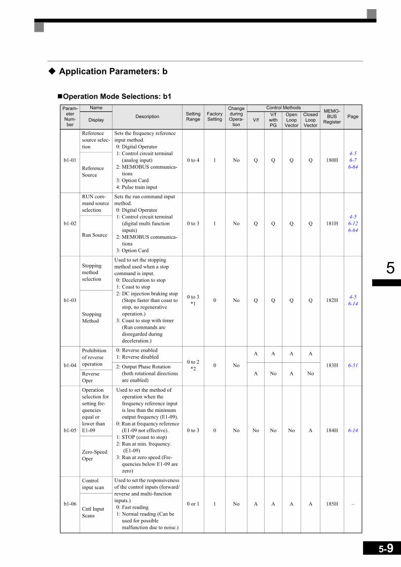
5
Application Parameters: b
Operation Mode Selections: b1Param-
eter Num-ber
Name
Description Setting Range
Factory Setting
Change during Opera-
tion
Control MethodsMEMO-
BUSRegister
PageV/f
V/f with PG
Open Loop
Vector
Closed Loop
VectorDisplay
b1-01
Reference source selec-tion
Sets the frequency reference input method.0: Digital Operator1: Control circuit terminal
(analog input)2: MEMOBUS communica-
tions3: Option Card4: Pulse train input
0 to 4 1 No Q Q Q Q 180H4-56-7
6-64Reference Source
b1-02
RUN com-mand source selection
Sets the run command input method.0: Digital Operator1: Control circuit terminal
(digital multi function inputs)
2: MEMOBUS communica-tions
3: Option Card
0 to 3 1 No Q Q Q Q 181H4-5
6-126-64
Run Source
b1-03
Stopping method selection
Used to set the stopping method used when a stop command is input.0: Deceleration to stop1: Coast to stop2: DC injection braking stop
(Stops faster than coast to stop, no regenerative operation.)
3: Coast to stop with timer (Run commands are disregarded during deceleration.)
0 to 3*1 0 No Q Q Q Q 182H 4-5
6-14
Stopping Method
b1-04
Prohibition of reverse operation
0: Reverse enabled1: Reverse disabled
0 to 2*2 0 No
A A A A
183H 6-512: Output Phase Rotation (both rotational directions are enabled)
A No A NoReverse Oper
b1-05
Operation selection for setting fre-quencies equal or lower than E1-09
Used to set the method of operation when the frequency reference input is less than the minimum output frequency (E1-09).
0: Run at frequency reference (E1-09 not effective).
1: STOP (coast to stop)2: Run at min. frequency.
(E1-09)3: Run at zero speed (Fre-
quencies below E1-09 are zero)
0 to 3 0 No No No No A 184H 6-14
Zero-Speed Oper
b1-06
Control input scan
Used to set the responsiveness of the control inputs (forward/reverse and multi-function inputs.)0: Fast reading 1: Normal reading (Can be
used for possible malfunction due to noise.)
0 or 1 1 No A A A A 185H –Cntl Input Scans
5-9

5-10
5
* 1. The setting range is 0 or 1 for Closed Loop Vector control.* 2. The setting range is 0 or 1 for Closed Loop Vector control an V/f control with PG
DC Injection Braking: b2
b1-07
Operation selection after switch-ing to remote mode
Used to set the operation mode when switching to the Remote mode using the Local/Remote Key.0: Run signals that are input
during mode switching are disregarded. (Input Run signals after switching the mode.)
1: Run signals become effective immediately after switching to the Remote mode.
0 or 1 0 No A A A A 186H -
LOC/REM RUN Sel
b1-08
Run com-mand selec-tion in program-ming modes
Used to set an operation prohi-bition in programming modes.0: Operation prohibited.1: Operation permitted
(Disabled when Digital Operator is the selected Run command source (b1-02 = 0)).
0 or 1 0 No A A A A 187H -
RUN CMD at PRG
Param-eter
Num-ber
Name
Description Setting Range
Factory Setting
Change during Opera-
tion
Control MethodsMEMO-
BUSRegister
PageV/f
V/f with PG
Open Loop
Vector
Closed Loop
VectorDisplay
b2-01
Zero speed level (DC injection braking starting fre-quency)
Used to set the frequency at which DC injection braking starts when b1-03 is set to 0 (deceleration to stop).When b2-01 is less than E1-09, E1-09 becomes the DC injection braking starting fre-quency.
0.0 to 10.0 0.5 Hz No A A A A 189H 6-14
6-17
DCInj Start Freq
b2-02
DC injec-tion braking current
Sets the DC injection braking current as a percentage of the inverter rated current.
0 to 100 50% No A A A A 18AH 6-14
6-17DCInj Current
b2-03
DC injec-tion braking time at start
Used to set the time to per-form DC injection braking at start in units of 1 second.Used to stop coasting motor and restart it. When the set value is 0, DC injection brak-ing at start is not performed.
0.00 to
10.000.00 s No A A A A 18BH 6-17
DCInj Time@Start
b2-04
DC injec-tion braking time at stop
Used to set the time to per-form DC injection braking at stop in units of 1 second.Used to prevent coasting after the stop command has been input. When the set value is 0.00, DC injection braking at stop is not performed.
0.00 to
10.000.50 s No A A A A 18CH 6-14
6-17DCInj Time@Stop
Param-eter
Num-ber
Name
Description Setting Range
Factory Setting
Change during Opera-
tion
Control MethodsMEMO-
BUSRegister
PageV/f
V/f with PG
Open Loop
Vector
Closed Loop
VectorDisplay
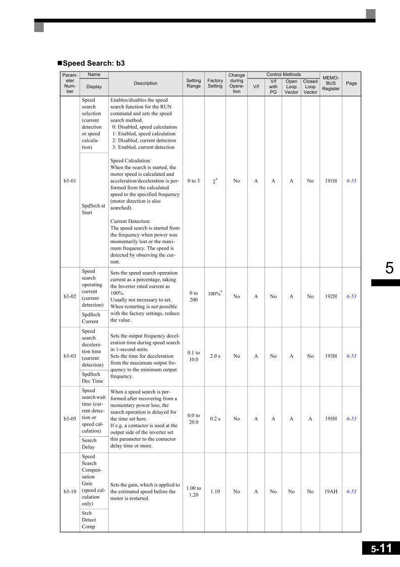
5
Speed Search: b3Param-
eter Num-ber
Name
Description Setting Range
Factory Setting
Change during Opera-
tion
Control MethodsMEMO-
BUSRegister
PageV/f
V/f with PG
Open Loop
Vector
Closed Loop
VectorDisplay
b3-01
Speed search selection (current detection or speed calcula-tion)
Enables/disables the speed search function for the RUN command and sets the speed search method.0: Disabled, speed calculation1: Enabled, speed calculation2: Disabled, current detection3: Enabled, current detection
Speed Calculation:When the search is started, the motor speed is calculated and acceleration/deceleration is per-formed from the calculated speed to the specified frequency (motor direction is also searched).
Current Detection:The speed search is started from the frequency when power was momentarily lost or the maxi-mum frequency. The speed is detected by observing the cur-rent.
0 to 3 2* No A A A No 191H 6-53
SpdSrch at Start
b3-02
Speed search operating current (current detection)
Sets the speed search operation current as a percentage, taking the Inverter rated current as 100%.Usually not necessary to set. When restarting is not possible with the factory settings, reduce the value.
0 to 200
100%*No A No A No 192H 6-53
SpdSrch Current
b3-03
Speed search decelera-tion time (current detection)
Sets the output frequency decel-eration time during speed search in 1-second units.Sets the time for deceleration from the maximum output fre-quency to the minimum output frequency.
0.1 to 10.0 2.0 s No A No A No 193H 6-53
SpdSrch Dec Time
b3-05
Speed search wait time (cur-rent detec-tion or speed cal-culation)
When a speed search is per-formed after recovering from a momentary power loss, the search operation is delayed for the time set here.If e.g. a contactor is used at the output side of the inverter set this parameter to the contactor delay time or more.
0.0 to 20.0 0.2 s No A A A A 195H 6-53
Search Delay
b3-10
Speed Search Compen-sation Gain (speed cal-culation only)
Sets the gain, which is applied to the estimated speed before the motor is restarted.
1.00 to 1.20 1.10 No A No No No 19AH 6-53
Srch Detect Comp
5-11

5-12
5
* The factory setting will change when the control method is changed. (Open Loop Vector factory settings are given.)
Timer Function: b4
b3-14
Speed Search Rotating Selection Direction
Selects the direction for the Speed Search operation.0: Speed Search is started using
the rotation direction from the frequency reference signal
1: Speed Search is started using the rotation direction from the estimated speed during speed search.
0 or 1 1 No A A A No 19EH 6-53
Bidir Search Sel
Param-eter
Num-ber
Name
Description Setting Range
Factory Setting
Change during Opera-
tion
Control MethodsMEMO-
BUSRegister
PageV/f
V/f with PG
Open Loop
Vector
Closed
Loop Vector
Display
b4-01
Timer func-tion ON-delay time
Sets the timer function output ON-delay time (dead time) for the timer function input.Enabled when a timer function is set in H1- and H2- .
0.0 to 3000.0 0.0 s No A A A A 1A3H 6-95
Delay-ON Timer
b4-02
Timer func-tion OFF-delay time
Sets the timer function output OFF-delay time (dead band) for the timer function input.Enabled when a timer function is set in H1- and H2-
0.0 to 3000.0 0.0 s No A A A A 1A4H 6-95
Delay-OFF Timer
Param-eter
Num-ber
Name
Description Setting Range
Factory Setting
Change during Opera-
tion
Control MethodsMEMO-
BUSRegister
PageV/f
V/f with PG
Open Loop
Vector
Closed Loop
VectorDisplay

5
PID Control: b5Param-
eter Num-ber
NameDescription Setting
RangeFactory Setting
Change during Opera-
tion
Control MethodsMEMO-
BUSRegister
PageV/f
V/f with PG
Open Loop
Vector
Closed Loop
VectorDisplay
b5-01
PID control mode selec-tion
0: Disabled1: Enabled (Deviation is D-
controlled.)2: Enabled (Feedback value
is D-controlled.)3: PID control enabled
(frequency reference + PID output, D control of deviation)
4: PID control enabled (frequency reference + PID output, D control of feedback value).
0 to 4 0 No A A A A 1A5H 6-96
PID Mode
b5-02
Proportional gain (P)
Sets P-control proportional gain.P-control is not performed when the setting is 0.00.
0.00 to
25.001.00 Yes A A A A 1A6H 6-96
PID Gain
b5-03Integral (I) time
Sets I-control integral time.I-control is not performed when the setting is 0.0.
0.0 to 360.0 1.0 s Yes A A A A 1A7H 6-96
PID I Time
b5-04Integral (I) limit
Sets the I-control limit as a percentage of the maximum output frequency.
0.0 to 100.0 100.0% Yes A A A A 1A8H 6-96
PID I Limit
b5-05
Differential (D) time
Sets D-control differential timeD-control is not performed when the setting is 0.00.
0.00 to 10.00 0.00 s Yes A A A A 1A9H 6-96
PID D Time
b5-06PID limit Sets the limit after PID-con-
trol as a percentage of the maximum output frequency.
0.0 to 100.0 100.0% Yes A A A A 1AAH 6-96
PID Limit
b5-07PID offset adjustment
Sets the offset after PID-con-trol as a percentage of the maximum output frequency.
-100.0 to
+100.00.0% Yes A A A A 1ABH 6-96
PID Offset
b5-08
PID delay time con-stant
Sets the time constant for low pass filter for PID-control out-put.Usually not necessary to set.
0.00 to 10.00 0.00 s Yes A A A A 1ACH 6-96
PID Delay Time
b5-09
PID output characteris-tics selection
Selects forward/reverse direc-tion for PID output.0: Normal PID output1: Reverse PID output
0 or 1 0 No A A A A 1ADH 6-96Output Level Sel
b5-10PID output gain Sets output gain. 0.0 to
25.0 1.0 No A A A A 1AEH 6-96Output Gain
b5-11
PID reverse output selec-tion
0: Limit to 0 when PID output is negative.
1: Reverses when PID output is negative.
Limit to 0 is also active when reverse prohibit is selected by using b1-04.
0 or 1 0 No A A A A 1AFH 6-96Output Rev Sel
5-13

5-14
5
b5-12
Selection of PID feed-back signal loss detec-tion
0: No detection of a feedback loss.
1: Detection of a feedback loss. (feedback under detection level) Operation continues during detection, the fault contact is not operated.
2: Detection of a feedback loss. (feedback under detection level) The motor coasts to stop at detection, and the fault contact operates.
3: Detection of a feedback loss. (feedback over detec-tion level)
Operation continues during detection, the fault contact is not operated.
4: Detection of a feedback loss. (feedback over detec-tion level)
The motor coasts to stop at detection, and the fault contact operates.
0 to 4 0 No A A A A 1B0H 6-96
Fb Los Det Sel
b5-13
PID feed-back loss detection level
Sets the PID feedback loss detection level as a percentage using the maximum output frequency as 100%.
0 to 100 0% No A A A A 1B1H 6-96
Fb los Det Lvl
b5-14
PID feed-back loss detection time
Sets the PID feedback loss detection time.
0.0 to 25.5 1.0 s No A A A A 1B2H 6-96
Fb los Det Time
b5-15
PID sleep function operation level
Sets the PID sleep function start level as a frequency.
0.0 to 150.0
*0.0 Hz No A A A A 1B3H 6-96
PID Sleep Level
b5-16
PID sleep operation delay time Sets the delay time until the
PID sleep function starts.0.0 to 25.5 0.0 s No A A A A 1B4H 6-96
PID Sleep Time
b5-17
Accel/decel time for PID reference Sets the accel/decel time for
PID reference.0.0 to 6000.0 0.0 s No A A A A 1B5H 6-96
PID Acc/Dec Time
b5-18
PID Set-point Selec-tion 0: Disabled
1: Enabled 0 to 1 0 No A A A A 1DCH 6-96PID Set-point Sel
Param-eter
Num-ber
NameDescription Setting
RangeFactory Setting
Change during Opera-
tion
Control MethodsMEMO-
BUSRegister
PageV/f
V/f with PG
Open Loop
Vector
Closed Loop
VectorDisplay

5
* The given setting range is valid if Heavy Duty is selected (C6-01=0, default setting). If Normal Duty 1 or 2 is selected (C6-01=1 or 2) the setting range will be 0.0 to 400.0 Hz.
b5-19PID Setpoint
PID-target value 0 to 100.0% 0 No A A A A 1DDH 6-96
PID Setpoint
b5-28
PID Square Root Feed-back Sel
Enables/Disables the square root function for the PID feed-back0: Disabled1: Enabled
0 or 1 0 No A A A A 1EAH 6-96
PID Fd SqRt
b5-29
Square root Feedback Gain Sets the gain for the PID
square root feedback function.0.00 to
2.00 1.00 No A A A A 1EBH 6-96PID Fd SqRt Gain
b5-31
PID feed-back moni-tor selection
Selects one of the inverters monitor items (U1- ) as PID feedback signal. The set-ting number is equal to the monitor item which has to be the feedback value.
0 to 18 0 No A A A A 1EDH 6-96PID Fb Mon Sel
b5-32
PID monitor feedback gain Sets the gain for the PID feed-
back signal.0.0 to 1000.0 100.0% No A A A A 1EEH 6-96
PID Fb Mon Gain
b5-33
PID monitor feedback bias Sets the bias for the PID feed-
back value
-100.0 to
100.00.0% No A A A A 1EFH 6-96
PID Fb Mon Bias
Param-eter
Num-ber
NameDescription Setting
RangeFactory Setting
Change during Opera-
tion
Control MethodsMEMO-
BUSRegister
PageV/f
V/f with PG
Open Loop
Vector
Closed Loop
VectorDisplay
5-15

5-16
5
Dwell Functions: b6
* The given setting range is valid if Heavy Duty is selected (C6-01=0, default setting). If Normal Duty 1 or 2 is selected (C6-01=1 or 2) the setting range will be 0.0 to 400.0 Hz
Droop Control: b7
Parameter
Num-ber
Name
DescriptionSet-ting
Range
Fac-tory
Setting
Change dur-
ing Opera-
tion
Control MethodsMEMO-
BUSRegister
PageV/f
V/f with PG
Open Loop
Vector
Closed Loop
VectorDisplay
b6-01
Dwell fre-quency at start
The dwell function can be used to hold the output frequency temporarily when driving a motor with a heavy load.
0.0 to 150.0
*0.0 Hz No A A A A 1B6H 6-22
Dwell Ref @ Start
b6-02
Dwell time at start 0.0 to
10.0 0.0 s No A A A A 1B7H 6-22Dwell Time @ Start
b6-03
Dwell fre-quency at stop
0.0 to 150.0
*0.0 Hz No A A A A 1B8H 6-22
Dwell Ref @ Stop
b6-04
Dwell time at stop 0.0 to
10.0 0.0 s No A A A A 1B9H 6-22Dwell Time @ Stop
Param-eter
Num-ber
NameDescription Setting
RangeFactory Setting
Change during Opera-
tion
Control MethodsMEMO-
BUSRegister
PageV/f
V/f with PG
Open Loop
Vector
Closed Loop
VectorDisplay
b7-01
Droop Con-trol Gain
Sets the Droop quantity at the rated speed and rated load as percentage of the maximum output frequency.
0.0 to 100.0 0.0% Yes No No No A 1CAH 6-124
Droop Quantity
b7-02
Droop Con-trol Delay Time
Sets the Droop Control delay time constant.Increase the value if hunting occurs.
0.03 to 2.00 0.05 s No No No No A 1CBH 6-124
Droop Delay Time
Run command
Output frequency
Time
ON
b6-03
OFF
b6-01
b6-04b6-02

5
Energy Saving: b8
* 1. The factory setting is given for Open Loop Vector control. The Closed Loop Vector control factory setting is 1.0.* 2. The factory setting is 2.00 s when Inverter capacity is 55 kW min.* 3. The factory settings depend on the Inverter capacity.
Param-eter
Num-ber
NameDescription Setting
RangeFactory Setting
Change during Opera-
tion
Control MethodsMEMO-
BUSRegister
PageV/f
V/f with PG
Open Loop
Vector
Closed Loop
VectorDisplay
b8-01
Energy-sav-ing mode selection
Select whether to enable or disable energy-saving control.0: Disable1: Enable
0 or 1 0 No A A A A 1CCH 6-106Energy Save Sel
b8-02
Energy-sav-ing gain Sets the energy-saving gain
for Open Loop and Closed Loop Vector control.
0.0 to 10.0
0.7*1 Yes No No A A 1CDH 6-106
Energy Save Gain
b8-03
Energy-sav-ing filter time con-stant
Sets the energy-saving filter time constant for Open Loop and Closed Loop Vector con-trol.
0.00 to 10.0
0.50 s*2 Yes No No A A 1CEH 6-106
Energy Save F.T
b8-04
Energy-sav-ing coeffi-cient
Sets the energy-saving coeffi-cient depending on the setting in E2-11 (motor rated cur-rent).Adjust the value in 5% steps until the output power becomes minimal.
0.0 to 655.00 *3 No A A No No 1CFH 6-106
Energy Save COEF
b8-05
Power detec-tion filter time con-stant
Sets the time constant for out-put power detection.
0 to 2000 20 ms No A A No No 1D0H 6-106
kW Filter Time
b8-06
Search oper-ation volt-age limiter
Sets the limit of the voltage control range during search operation. 100% is the moni-tor rated voltage.
0 to 100 0% No A A No No 1D1H 6-106Search V Limit
5-17

5-18
5
Zero Servo Control: b9Param-
eter Num-ber
NameDescription Setting
RangeFactory Setting
Change during Opera-
tion
Control MethodsMEMO-
BUSRegister
PageV/f
V/f with PG
Open Loop
Vector
Closed Loop
VectorDisplay
b9-01
Zero Servo Gain
Adjust the strength of the zero-servo lock.Enabled when the “zero-servo command” is set for a multi-function input. When the zero-servo command has been input and the frequency refer-ence drops below DC Injec-tion level (b2-01), a position control loop is created and the motor stops. Increasing the zero-servo gain increases the strength of the lock. Increas-ing it by much causes oscilla-tions.
0 to 100 5 No No No No A 1DAH 6-125Zero Servo Gain
b9-02
Zero-Servo completion bandwidth
Sets the bandwidth of the Zero Servo completion output.Enabled when the “zero-servo completion (end)” is set for a multi-function output. The zero-servo completion signal is ON when the current posi-tion is within the range (the zero-servo position + zero-servo completion width.)Set b9-02 to 4 times of the allowable displacement pulse amount at the PG.
0 to 16383 10 No No No No A 1DBH 6-125
Zero Servo Count

5
Tuning Parameters: C
Acceleration/Deceleration: C1
* 1. The setting range for acceleration/deceleration times will depends on the setting for C1-10. When C1-10 is set to 0, the setting range for acceleration/deceleration times becomes 0.00 to 600.00 seconds.
* 2. The given setting range is valid if Heavy Duty is selected (C6-01=0, default setting). If Normal Duty 1 or 2 is selected (C6-01=1 or 2) the setting range will be 0.0 to 400.0 Hz
Param-eter
Num-ber
NameDescription Setting
RangeFactory Setting
Change during Opera-
tion
Control MethodsMEMO-
BUSRegister
PageV/f
V/f with PG
Open Loop
Vector
Closed Loop
VectorDisplay
C1-01Acceleration time 1
Sets the acceleration time to accelerate from 0 Hz to the maximum output frequency.
0.0 to 6000.0
*110.0 s
Yes Q Q Q Q 200H 4-56-19
Accel Time 1
C1-02Deceleration time 1
Sets the deceleration time to decelerate from the maximum output frequency to 0 Hz.
Yes Q Q Q Q 201H 4-56-19
Decel Time 1
C1-03Acceleration time 2
Sets the acceleration time when the multi-function input “accel/decel time 1” is set to ON.
Yes A A A A 202H 6-19Accel Time 2
C1-04Deceleration time 2
Sets the deceleration time when the multi-function input “accel/decel time 1” is set to ON.
Yes A A A A 203H 6-19Decel Time 2
C1-05Acceleration time 3
Sets the acceleration time when the multi-function input “accel/decel time 2” is set to ON.
No A A A A 204H 6-19Accel Time 3
C1-06Deceleration time 3
Sets the deceleration time when the multi-function input “accel/decel time 2” is set to ON.
No A A A A 205H 6-19Decel Time 3
C1-07
Acceleration time 4
Sets the acceleration time when the multi-function input “accel/decel time 1” and “accel/decel time 2” are set to ON.
No A A A A 206H 6-19Accel Time 4
C1-08
Deceleration time 4
Sets the deceleration time when the multi-function input “accel/decel time 1” and “accel/decel time 2” are set to ON.
No A A A A 207H 6-19Decel Time 4
C1-09
Emergency stop time
Sets the deceleration time when the multi-function input “Emergency (fast) stop” is set to ON.
No A A A A 208H 6-19Fast Stop Time
C1-10
Accel/decel time setting unit 0: 0.01-second units
1: 0.1-second units 0 or 1 1 No A A A A 209H 6-19Acc/Dec Units
C1-11
Accel/decel time switch-ing fre-quency
Sets the frequency for auto-matic acceleration/decelera-tion switching.If the output frequency is below the set frequency: Accel/decel time 4If the output frequency is above the set frequency: Accel/decel time 1The multi-function input “accel/decel time 1” or “accel/decel time 2” has priority.
0.0 to 150.0
*20.0 Hz No A A A A 20AH 6-19
Acc/Dec SW Freq
5-19
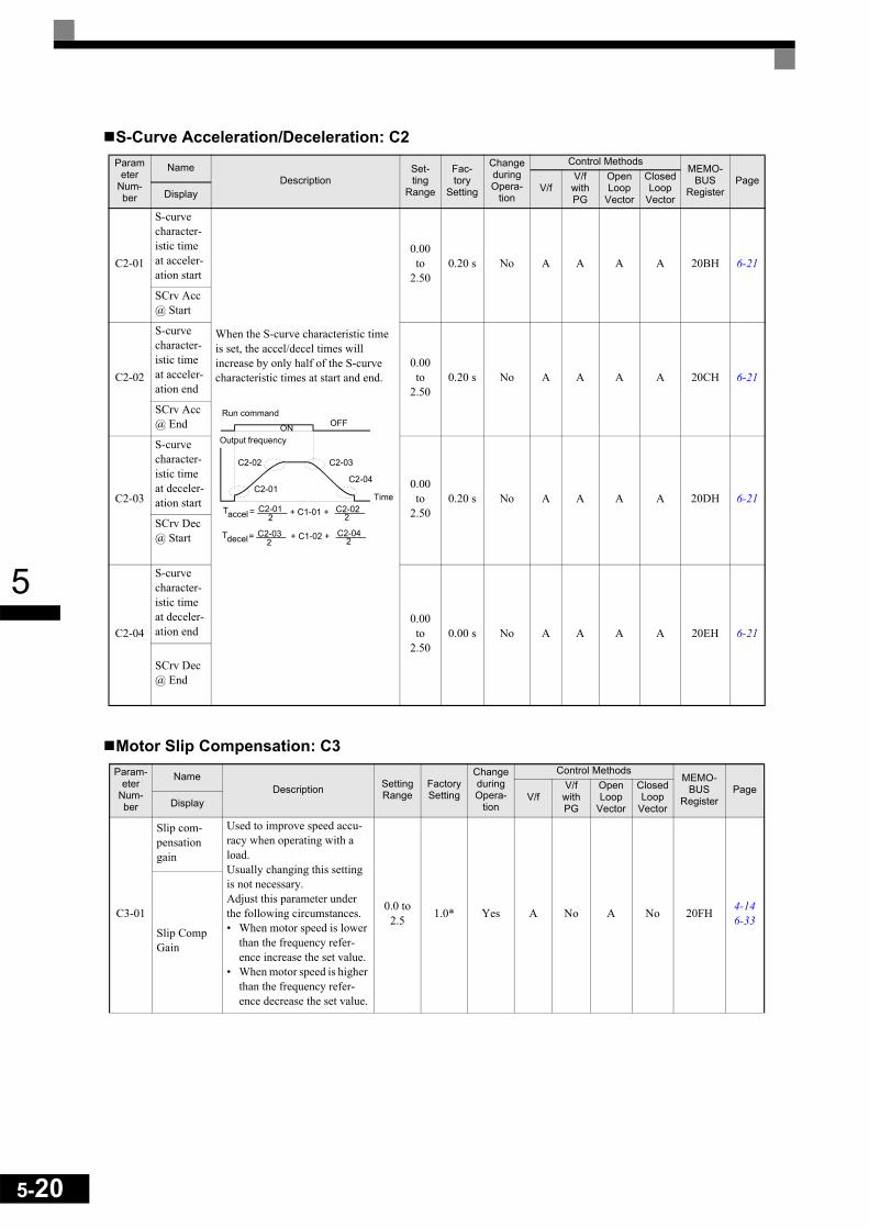
5-20
5
S-Curve Acceleration/Deceleration: C2
Motor Slip Compensation: C3
Parameter
Num-ber
NameDescription
Set-ting
Range
Fac-tory
Setting
Change during Opera-
tion
Control MethodsMEMO-
BUSRegister
PageV/f
V/f with PG
Open Loop
Vector
Closed Loop
VectorDisplay
C2-01
S-curve character-istic time at acceler-ation start
When the S-curve characteristic time is set, the accel/decel times will increase by only half of the S-curve characteristic times at start and end.
0.00 to
2.500.20 s No A A A A 20BH 6-21
SCrv Acc @ Start
C2-02
S-curve character-istic time at acceler-ation end
0.00 to
2.500.20 s No A A A A 20CH 6-21
SCrv Acc @ End
C2-03
S-curve character-istic time at deceler-ation start
0.00 to
2.500.20 s No A A A A 20DH 6-21
SCrv Dec @ Start
C2-04
S-curve character-istic time at deceler-ation end
0.00 to
2.500.00 s No A A A A 20EH 6-21
SCrv Dec @ End
Param-eter
Num-ber
NameDescription Setting
RangeFactory Setting
Change during Opera-
tion
Control MethodsMEMO-
BUSRegister
PageV/f
V/f with PG
Open Loop
Vector
Closed Loop
VectorDisplay
C3-01
Slip com-pensation gain
Used to improve speed accu-racy when operating with a load.Usually changing this setting is not necessary.Adjust this parameter under the following circumstances.• When motor speed is lower
than the frequency refer-ence increase the set value.
• When motor speed is higher than the frequency refer-ence decrease the set value.
0.0 to 2.5 1.0* Yes A No A No 20FH 4-14
6-33Slip Comp Gain
Run command
Output frequency
Time
ON OFF
C2-02 C2-03
C2-04C2-01
accelT = C2-012 + C1-01 + C2-02
2
decelT = C2-032
+ C1-02 + C2-042

5
* The factory setting will change when the control method is changed. (The Open Loop Vector control factory settings are given.)
C3-02
Slip com-pensation delay time
Sets the Slip Compensation delay time.Usually changing this setting is not necessary.Adjust this parameter under the following circumstances.• Reduce the setting when
Slip Compensation respon-siveness is low.
• When speed is not stable, increase the setting.
0 to 10000
200 ms* No A No A No 210H 4-14
6-33Slip Comp Time
C3-03
Slip com-pensation limit
Sets the slip compensation limit as a percentage of motor rated slip.
0 to 250 200% No A No A No 211H 6-33
Slip Comp Limit
C3-04
Slip com-pensation selection during regeneration
0: Disabled.1: Enabled.
When the slip compensation during regeneration function has been activated and regen-eration capacity increases momentarily, it might be nec-essary to use a braking option (braking resistor, braking resistor unit or braking unit.)
0 or 1 0 No A No A No 212H 6-33
Slip Comp Regen
C3-05
Output volt-age limit operation selection
0: Disabled.1: Enabled. (The motor flux
will be lowered automatically when the output voltage become saturated.)
0 or 1 0 No No No A A 213H 6-33
V/f Slip Comp Sel
Param-eter
Num-ber
NameDescription Setting
RangeFactory Setting
Change during Opera-
tion
Control MethodsMEMO-
BUSRegister
PageV/f
V/f with PG
Open Loop
Vector
Closed Loop
VectorDisplay
5-21
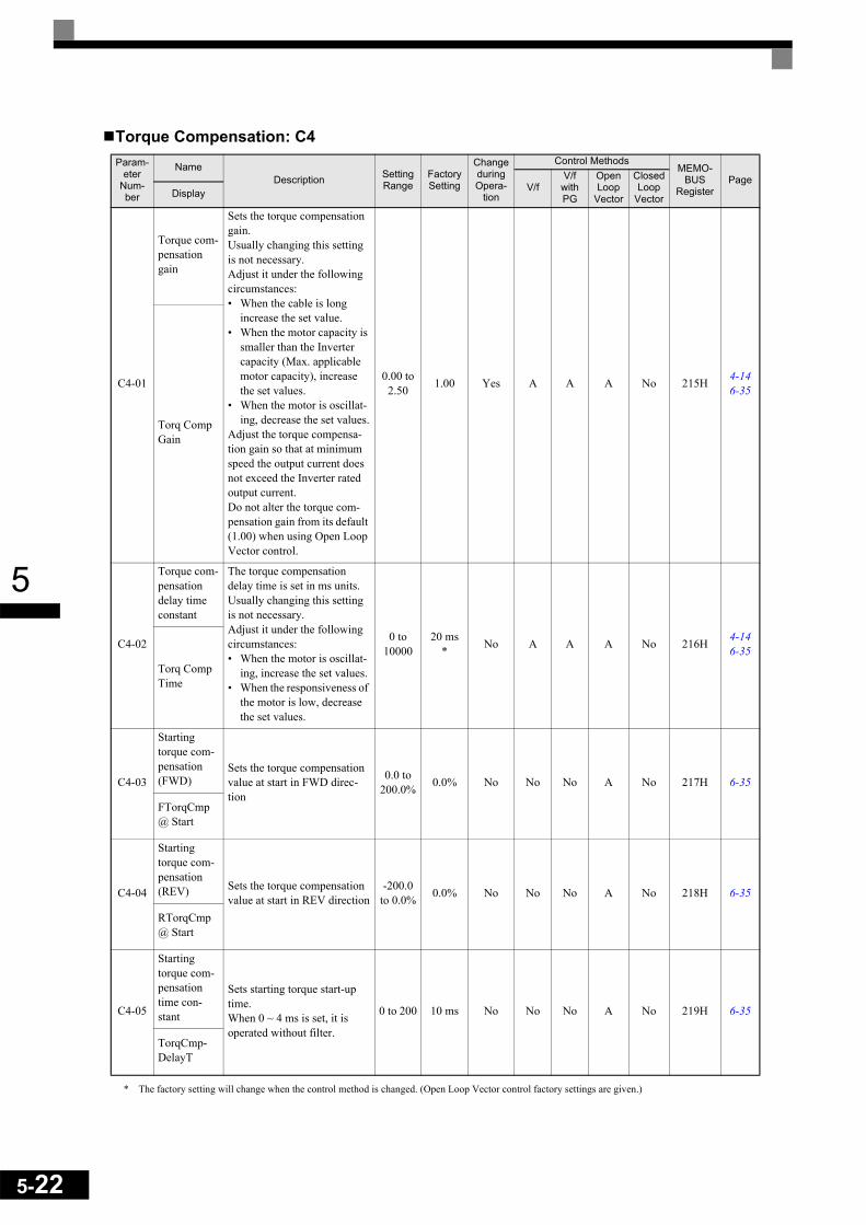
5-22
5
Torque Compensation: C4
* The factory setting will change when the control method is changed. (Open Loop Vector control factory settings are given.)
Param-eter
Num-ber
NameDescription Setting
RangeFactory Setting
Change during Opera-
tion
Control MethodsMEMO-
BUSRegister
PageV/f
V/f with PG
Open Loop
Vector
Closed Loop
VectorDisplay
C4-01
Torque com-pensation gain
Sets the torque compensation gain.Usually changing this setting is not necessary.Adjust it under the following circumstances:• When the cable is long
increase the set value.• When the motor capacity is
smaller than the Inverter capacity (Max. applicable motor capacity), increase the set values.
• When the motor is oscillat-ing, decrease the set values.
Adjust the torque compensa-tion gain so that at minimum speed the output current does not exceed the Inverter rated output current. Do not alter the torque com-pensation gain from its default (1.00) when using Open Loop Vector control.
0.00 to 2.50 1.00 Yes A A A No 215H 4-14
6-35
Torq Comp Gain
C4-02
Torque com-pensation delay time constant
The torque compensation delay time is set in ms units.Usually changing this setting is not necessary.Adjust it under the following circumstances:• When the motor is oscillat-
ing, increase the set values.• When the responsiveness of
the motor is low, decrease the set values.
0 to 10000
20 ms* No A A A No 216H 4-14
6-35Torq Comp Time
C4-03
Starting torque com-pensation (FWD)
Sets the torque compensation value at start in FWD direc-tion
0.0 to 200.0% 0.0% No No No A No 217H 6-35
FTorqCmp @ Start
C4-04
Starting torque com-pensation (REV) Sets the torque compensation
value at start in REV direction-200.0
to 0.0% 0.0% No No No A No 218H 6-35
RTorqCmp @ Start
C4-05
Starting torque com-pensation time con-stant
Sets starting torque start-up time.When 0 ~ 4 ms is set, it is operated without filter.
0 to 200 10 ms No No No A No 219H 6-35
TorqCmp-DelayT

5
Speed Control (ASR): C5
* 1. The setting range is 1.00 to 300.00 if Closed Loop Vector control is used.* 2. When the control method is changed, these values are reset to factory settings for the selected control mode. (The Closed Loop Vector control factory
settings are given)* 3. The given setting range is valid if Heavy Duty is selected (C6-01=0, default setting). If Normal Duty 1 or 2 is selected (C6-01=1 or 2) the setting range
will be 0.0 to 400.0 Hz
Parameter
Num-ber
Name
DescriptionSet-ting
Range
Fac-tory
Setting
Change during Opera-
tion
Control MethodsMEMO-
BUSRegister
PageV/f
V/f with PG
Open Loop
Vector
Closed Loop
VectorDisplay
C5-01
ASR pro-portional (P) gain 1 Sets the proportional gain of the
speed loop (ASR)
0.00 to 300.00
*1
20.00*2 Yes No A No A 21BH 6-36
ASR P Gain 1
C5-02
ASR inte-gral (I) time 1 Sets the integral time of the speed
loop (ASR).
0.000 to
10.000
0.500 s*2 Yes No A No A 21CH 6-36
ASR I Time 1
C5-03
ASR pro-portional (P) gain 2
Usually changing this setting is not necessary.
0.00 to 300.00
*1
20.00*2 Yes No A No A 21DH 6-36
ASR P Gain 2
C5-04
ASR inte-gral (I) time 2
0.000 to
10.000
0.500 s*2 Yes No A No A 21EH 6-36
ASR I Time 2
C5-05
ASR limit Sets the upper limit for the compen-sation frequency for the speed con-trol loop (ASR) as a percentage of the maximum output frequency.
0.0 to 20.0 5.0% No No A No No 21FH 6-36
ASR Limit
C5-06
ASR delay time Sets the filter time constant; the time
from the speed loop to the torque command output. Usually changing this setting is not necessary.
0.000 to
0.500
0.004ms No No No No A 220H 6-36ASR
Delay Time
C5-07
ASR switching frequency
Sets the frequency for switching between Proportion Gain 1, 2 and Integral Time 1, 2.
0.0 to 150.0
*30.0 Hz No No No No A 221H 6-36
ASR Gain SW Freq
C5-08
ASR inte-gral (I) limit
Set the parameter to a small value to prevent any radical load change. A setting of 100% is equal to the maxi-mum output frequency.
0 to 400 400% No No No No A 222H 6-36
ASR I Limit
P,I
0 E1-04
P = C5-01I = C5-02
P = C5-03I = C5-04
Motor speed (Hz)
5-23

5-24
5
Carrier Frequency: C6
* 1. The setting range depends on the capacity of the Inverter.* 2. This parameter can be monitored or set only when 1 is set for C6-01 and F is set for C6-02.
Parameter
Num-ber
NameDescription
Set-ting
Range
Fac-tory
Setting
Change during Opera-
tion
Control MethodsMEMO-
BUSRegister
PageV/f
V/f with PG
Open Loop
Vector
Closed Loop
VectorDisplay
C6-01
Heavy/Normal Duty selec-tion
0: Heavy Duty 1: Normal Duty 12: Normal Duty 2
0 to 2 0 No Q Q Q Q 223H 4-56-2
Heavy/Normal Duty
C6-02
Carrier fre-quency selection
Selects the carrier frequency.Select F to enable detailed settings using parameters C6-03 to C6-05.0: Low carrier, low noise1: 2 kHz2: 5 kHz3: 8 kHz4: 10 kHz5: 12.5 kHz6: 15 kHzF: User setting
0 to F 1 No Q Q Q Q 224H4-54-146-2Carrier
Freq Sel
C6-03
Carrier fre-quency upper limit
Sets the carrier frequency upper limit and lower limit in kHz units.The carrier frequency gain is set as follows:In the Open Loop and Closed Loop Vector control, the upper limit of the carrier frequency is fixed with C6-03.
K is a coefficient that depends on the setting of C6-03.C6-03 ≥ 10.0 kHz: K = 310.0 kHz > C6-03 ≥ 5.0 kHz: K = 25.0 kHz > C6-03: K = 1
2.0 to 15.0*1 *2
2.0 kHz No A A A A 225H 6-2
Carrier Freq Max
C6-04
Carrier fre-quency lower limit
0.4 to 15.0
*1 *2
2.0 kHz No A A No No 226H 6-2
Carrier Freq Gain
C6-05
Carrier fre-quency propor-tional gain
00 to 99*2
00 No A A No No 227H 6-2
Carrier Freq Sel
Carrier frequency
Output frequency x (C6-05) x
(Max. output frequency)
Outputfrequency

5
Reference Parameters: d
Preset Reference: d1Param-
eter Num-ber
NameDescription Setting
RangeFactory Setting
Change during Opera-
tion
Control MethodsMEMO-
BUSRegister
PageV/f
V/f with PG
Open Loop
Vector
Closed Loop
VectorDisplay
d1-01Frequency reference 1 Sets the frequency reference.
0 to 50.00*1*2
0.00 Hz Yes Q Q Q Q 280H 4-56-10
Reference 1
d1-02
Frequency reference 2
Sets the frequency reference when multi-step speed com-mand 1 is ON for a multi-function input.
0.00 Hz Yes Q Q Q Q 281H 4-56-10
Reference 2
d1-03
Frequency reference 3
Sets the frequency reference when multi-step speed com-mand 2 is ON for a multi-function input.
0.00 Hz Yes Q Q Q Q 282H 4-56-10
Reference 3
d1-04
Frequency reference 4
Sets the frequency reference when multi-step speed com-mands 1 and 2 are ON for multi-function inputs.
0.00 Hz Yes Q Q Q Q 283H 4-56-10
Reference 4
d1-05
Frequency reference 5
Sets the frequency when multi-step speed command 3 is ON for a multi-function input.
0.00 Hz Yes A A A A 284H 6-10Reference 5
d1-06
Frequency reference 6
Sets the frequency reference when multi-step speed com-mands 1 and 3 are ON for multi-function inputs.
0.00 Hz Yes A A A A 285H 6-10Reference 6
d1-07
Frequency reference 7
Sets the frequency reference when multi-step speed com-mands 2 and 3 are ON for multi-function inputs.
0.00 Hz Yes A A A A 286H 6-10Reference 7
d1-08
Frequency reference 8
Sets the frequency reference when multi-step speed com-mands 1, 2, and 3 are ON for multi-function inputs.
0.00 Hz Yes A A A A 287H 6-10Reference 8
d1-09
Frequency reference 9
Sets the frequency reference when multi-step speed com-mand 4 is ON for a multi-function input.
0.00 Hz Yes A A A A 288H 6-10Reference 9
d1-10
Frequency reference 10
Sets the frequency reference when multi-step speed com-mands 1 and 4 are ON for multi-function inputs.
0.00 Hz Yes A A A A 28BH 6-10Reference 10
d1-11
Frequency reference 11
Sets the frequency reference when multi-step speed com-mands 2 and 4 are ON for a multi-function inputs.
0.00 Hz Yes A A A A 28CH 6-10Reference 11
5-25

5-26
5
* 1. The unit is set in o1-03 (frequency units of reference setting and monitor, default: 0.01 Hz). If the display unit is changed, the setting range values alsochange* 2. The maximum setting value depends on the setting of the maximum output frequency (E1-04).
Reference Limits: d2
d1-12
Frequency reference 12
Sets the frequency reference when multi-step speed com-mands 1, 2, and 4 are ON for multi-function inputs.
0 to 50.00*1*2
0.00 Hz Yes A A A A 28DH 6-10Reference 12
d1-13
Frequency reference 13
Sets the frequency reference when multi-step speed com-mands 3 and 4 are ON for multi-function inputs.
0.00 Hz Yes A A A A 28EH 6-10Reference 13
d1-14
Frequency reference 14
Sets the frequency reference when multi-step speed com-mands 1, 3, and 4 are ON for multi-function inputs.
0.00 Hz Yes A A A A 28FH 6-10Reference 14
d1-15
Frequency reference 15
Sets the frequency reference when multi-step speed com-mands 2, 3, and 4 are ON for multi-function inputs.
0.00 Hz Yes A A A A 290H 6-10Reference 15
d1-16
Frequency reference 16
Sets the frequency reference when multi-step speed com-mands 1, 2, 3, and 4 are ON for multi-function inputs.
0.00 Hz Yes A A A A 291H 6-10Reference 16
d1-17
Jog fre-quency ref-erence
Sets the frequency reference when the jog frequency refer-ence selection, FJOG com-mand, or RJOG command is ON.
6.00 Hz Yes Q Q Q Q 292H4-5
6-106-72Jog Refer-
ence
Param-eter
Num-ber
NameDescription Setting
RangeFactory Setting
Change during Opera-
tion
Control MethodsMEMO-
BUSRegister
PageV/f
V/f with PG
Open Loop
Vector
Closed Loop
VectorDisplay
d2-01
Frequency reference upper limit
Sets the frequency reference upper limit as a percentage of the max. output frequency.
0.0 to 110.0 100.0% No A A A A 289H 6-30
6-67Ref Upper Limit
d2-02
Frequency reference lower limit
Sets the frequency reference lower limit as a percentage of the maximum output fre-quency.
0.0 to 110.0 0.0% No A A A A 28AH 6-30
6-67Ref Lower Limit
d2-03
Master speed refer-ence lower limit
Sets the master speed refer-ence lower limit as a percent-age of the max. output frequency.
0.0 to 110.0 0.0% No A A A A 293H 6-30
6-67Ref1 Lower Limit
Param-eter
Num-ber
NameDescription Setting
RangeFactory Setting
Change during Opera-
tion
Control MethodsMEMO-
BUSRegister
PageV/f
V/f with PG
Open Loop
Vector
Closed Loop
VectorDisplay

5
Jump Frequencies: d3
* The given setting range is valid if Heavy Duty is selected (C6-01=0, default setting). If Normal Duty 1 or 2 is selected (C6-01=1 or 2) the setting range will be 0.0 to 400.0 Hz
Reference Frequency Hold: d4
Param-eter
Num-ber
NameDescription Setting
RangeFactory Setting
Change during Opera-
tion
Control MethodsMEMO-
BUSRegister
PageV/f
V/f with PG
Open Loop
Vector
Closed Loop
VectorDisplay
d3-01Jump fre-quency 1
Set the center values of the jump frequencies in Hz.This function is disabled when the jump frequency is set to 0 Hz. Always ensure that the following applies:d3-01 ≥ d3-02 ≥ d3-03Operation in the jump fre-quency range is prohibited but during acceleration and decel-eration, the speed changes smoothly without jumping
0.0 to 150.0
*
0.0 Hz No A A A A 294H 6-28Jump Freq 1
d3-02Jump fre-quency 2 0.0 Hz No A A A A 295H 6-28Jump Freq 2
d3-03
Jump fre-quency 3
0.0 Hz No A A A A 296H 6-28Jump Freq 3
d3-04
Jump fre-quency width
Sets the jump frequency band-width in Hz.The jump frequency range will be the jump frequency ± d3-04.
0.0 to 20.0 1.0 Hz No A A A A 297H 6-28
Jump Bandwidth
Param-eter
Num-ber
NameDescription Setting
RangeFactory Setting
Change during Opera-
tion
Control MethodsMEMO-
BUSRegister
PageV/f
V/f with PG
Open Loop
Vector
Closed Loop
VectorDisplay
d4-01
Frequency reference hold func-tion selec-tion
Sets whether the frequency reference value on hold or power loss will be recorded or not.0: Disabled (when operation
is stopped or the power is turned on again the fre-quency reference is set to 0.)
1: Enabled (when operation is stopped or the power is turned on again the inverter starts at the previous hold frequency.)
This function is available when the multi-function inputs “Accel/Decel Ramp Hold” or “Up/Down” com-mands are set.
0 or 1 0 No A A A A 298H 6-66
MOP Ref Memory
d4-02
+ – Speed limits
Sets the frequency to be add to or subtracted from the analog frequency reference as a per-centage of the max. output fre-quency.Enabled when the increase (+) speed command or decrease(–) speed command is set for a multi-function input.
0 to 100 10% No A A A A 299H 6-66Trim Con-trol Lvl
5-27

5-28
5
Torque Control: d5Param-
eter Num-ber
NameDescription Setting
RangeFactory Setting
Change during Opera-
tion
Control MethodsMEMO-
BUSRegister
PageV/f
V/f with PG
Open Loop
Vector
Closed Loop
VectorDisplay
d5-01
Torque con-trol selection
0: Speed control (C5-01 to C5-07)
1: Torque controlThis function is available in Closed Loop Vector control mode only. To use the func-tion for switching between speed and torque control, set d5-01 to 0 and set the multi-function input to “speed/torque control change.”
0 or 1 0 No No No No A 29AH 6-118Torq Control Sel
d5-02
Torque ref-erence delay time
Sets the torque reference delay time.It can be used to prevent oscil-lations caused by signal noise or to increase or decrease the responsiveness.When oscillation occurs dur-ing torque control, increase the set value.
0 to 1000 0 ms No No No No A 29BH 6-118
Torq Ref Filter
d5-03
Speed limit selection
Sets the speed limit reference source for the torque control mode.1: The analog input limit
from a frequency reference2: Limited by d5-04 parame-
ter setting values.
1 or 2 1 No No No No A 29CH 6-118Speed Limit Sel
d5-04
Speed limitSets the speed limit during torque control as a percentage of the maximum output fre-quency.This function is enabled when d5-03 is set to 2. Directions are as follows.+: run command direction-: run command opposite direction
-120 to +120 0% No No No No A 29DH 6-118
Speed Lmt Value
d5-05
Speed limit bias
Sets the speed limit bias as a percentage of the maximum output frequency.The bias is applied to the spec-ified speed limit. It can be used to adjust the margin for the speed limit.
0 to 120 10% No No No No A 29EH 6-118Speed Lmt Bias
d5-06
Speed/torque con-trol switch-ing timer
Sets the delay time from inputting a “speed/torque control change” (Digital input from On to OFF or OFF to ON) until the control is actu-ally changed.This function is enabled when the multi-function input “speed/torque control change” is set. The analog inputs val-ues are hold from the point, when the “speed/torque con-trol change” is activated.
0 to 1000 0 ms No No No No A 29FH 6-118
Ref Hold Time

5
Field Weakening: d6
* The given setting range is valid if Heavy Duty is selected (C6-01=0, default setting). If Normal Duty 1 or 2 is selected (C6-01=1 or 2) the setting range will be 0.0 to 400.0 Hz
Param-eter
Num-ber
NameDescription Setting
RangeFactory Setting
Change during Opera-
tion
Control MethodsMEMO-
BUSRegister
PageV/f
V/f with PG
Open Loop
Vector
Closed Loop
VectorDisplay
d6-01
Field weak-ening level
Sets the inverter output volt-age when the field weakening command is input at a digital input.Sets the voltage level as a per-centage taking the voltage set by the V/f pattern as 100%.
0 to 100 80% No A A No No 2A0H 6-107Field-Weak Lvl
d6-02
Field weak-ening fre-quency limit
Sets the lower limit of the fre-quency range where field con-trol is valid.The field weakening com-mand is accepted only at fre-quencies above this setting and only when the speed is in agreement with the current speed reference.
0.0 to 150.0
*0.0 Hz No A A No No 2A1H 6-107
Field-Weak Freq
d6-03
Field forc-ing function selection
Enables or disables field forc-ing function.0: Disabled1: Enabled
0 or 1 0 No No No No A 2A2H 6-108Field Force Sel
d6-06
Field forc-ing function Limit
Sets the upper limit for the excitation current applied by the field forcing function.A setting of 100% is equal to the motor no-load current.Field forcing is active during all types of operation except DC Injection.
100 to 400 400% No No No A A 2A5H 6-108
FieldForce Limit
5-29
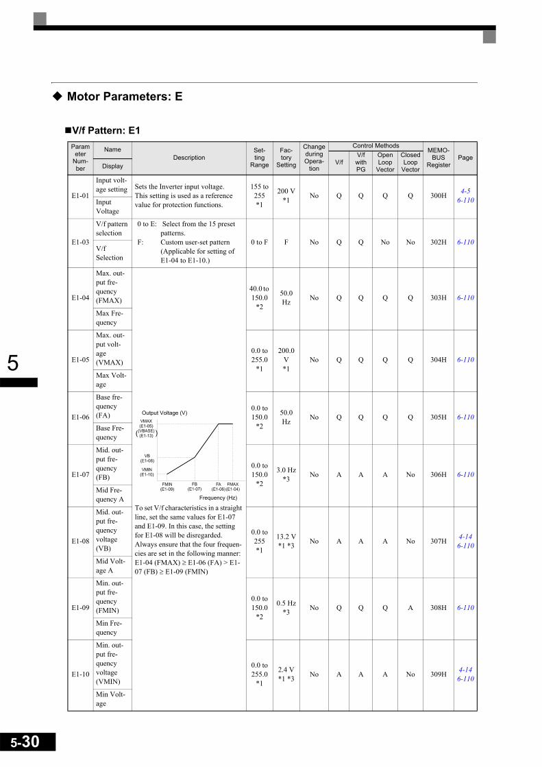
5-30
5
Motor Parameters: E
V/f Pattern: E1Param
eter Num-ber
NameDescription
Set-ting
Range
Fac-tory
Setting
Change during Opera-
tion
Control MethodsMEMO-
BUSRegister
PageV/f
V/f with PG
Open Loop
Vector
Closed Loop
VectorDisplay
E1-01
Input volt-age setting Sets the Inverter input voltage.
This setting is used as a reference value for protection functions.
155 to 255*1
200 V*1 No Q Q Q Q 300H 4-5
6-110Input Voltage
E1-03
V/f pattern selection
0 to E: Select from the 15 preset patterns.
F: Custom user-set pattern (Applicable for setting of E1-04 to E1-10.)
0 to F F No Q Q No No 302H 6-110V/f Selection
E1-04
Max. out-put fre-quency(FMAX)
To set V/f characteristics in a straight line, set the same values for E1-07 and E1-09. In this case, the setting for E1-08 will be disregarded.Always ensure that the four frequen-cies are set in the following manner:E1-04 (FMAX) ≥ E1-06 (FA) > E1-07 (FB) ≥ E1-09 (FMIN)
40.0 to 150.0
*2
50.0 Hz No Q Q Q Q 303H 6-110
Max Fre-quency
E1-05
Max. out-put volt-age (VMAX)
0.0 to 255.0
*1
200.0 V*1
No Q Q Q Q 304H 6-110
Max Volt-age
E1-06
Base fre-quency (FA)
0.0 to 150.0
*2
50.0 Hz No Q Q Q Q 305H 6-110
Base Fre-quency
E1-07
Mid. out-put fre-quency (FB)
0.0 to 150.0
*2
3.0 Hz*3 No A A A No 306H 6-110
Mid Fre-quency A
E1-08
Mid. out-put fre-quency voltage (VB)
0.0 to 255 *1
13.2 V*1 *3 No A A A No 307H 4-14
6-110
Mid Volt-age A
E1-09
Min. out-put fre-quency (FMIN)
0.0 to 150.0
*2
0.5 Hz*3 No Q Q Q A 308H 6-110
Min Fre-quency
E1-10
Min. out-put fre-quency voltage (VMIN)
0.0 to 255.0
*1
2.4 V*1 *3 No A A A No 309H 4-14
6-110
Min Volt-age
Output Voltage (V)
Frequency (Hz)

5
* 1. These are values for a 200 V Class Inverter. Values for a 400 V Class Inverter are double.* 2. The given setting range is valid if Heavy Duty is selected (C6-01=0, default setting). If Normal Duty 1 or 2 is selected (C6-01=1 or 2) the setting range
will be 0.0 to 400.0 Hz* 3. The factory setting will change when the control method is changed. (The Open Loop Vector Control factory settings are given.)* 4. E1-11 and E1-12 are disregarded when set to 0.0.* 5. E1-13 is set to the same value as E1-05 by autotuning.
Motor Setup: E2
E1-11
Mid. out-put fre-quency 2
Set only to fine-adjust V/f for the output range. Normally, this setting is not required.E1-11 must be set higher than E1-04.
0.0 to 150.0
*2
0.0 Hz*4 No A A A A 30AH 6-110
Mid Fre-quency B
E1-12
Mid. out-put fre-quency voltage 2
0.0 to 255.0
*1
0.0 V*4 No A A A A 30BH 6-110
Mid Volt-age B
E1-13
Base volt-age (VBASE) Sets the output voltage of the base
frequency (E1-06).
0.0 to 255.0
*1
0.0 V*5 No A A Q Q 30CH 6-110
Base Volt-age
Param-eter
Num-ber
NameDescription Setting
RangeFactory Setting
Change during Opera-
tion
Control MethodsMEMO-
BUSRegister
PageV/f
V/f with PG
Open Loop
Vector
Closed Loop
VectorDisplay
E2-01
Motor rated current
Sets the motor rated current.This set value will become the reference value for motor pro-tection and torque limits.This parameter is an input data for autotuning.
0.32 to 6.40*1
1.90 A*2 No Q Q Q Q 30EH 6-48
6-108Motor Rated FLA
E2-02
Motor rated slip
Sets the motor rated slip.This set value will become the reference value for the slip compensation.This parameter is automati-cally set during autotuning.
0.00 to 20.00
2.90 Hz*2 No A A A A 30FH 6-108
Motor Rated Slip
E2-03
Motor no-load current
Sets the motor no-load cur-rent.This parameter is automati-cally set during autotuning.
0.00 to 1.89*3
1.20 A*2 No A A A A 310H 6-108
No-Load Current
E2-04
Number of motor poles
Sets the number of motor poles.This value is an input data for autotuning.
2 to 48 4 poles No No Q Q Q 311H 6-108Number of Poles
E2-05
Motor line-to-line resis-tance
Sets the motor phase-to-phase resistance.This parameter is automati-cally set during autotuning.
0.000 to
65.000
9.842 Ω*2 No A A A A 312H 6-108
Term Resis-tance
E2-06
Motor leak inductance
Sets the voltage drop due to motor leakage inductance as a percentage of the motor rated voltage.This parameter is automati-cally set during autotuning.
0.0 to 40.0
18.2%*2 No No No A A 313H 6-108
Leak Induc-tance
Parameter
Num-ber
NameDescription
Set-ting
Range
Fac-tory
Setting
Change during Opera-
tion
Control MethodsMEMO-
BUSRegister
PageV/f
V/f with PG
Open Loop
Vector
Closed Loop
VectorDisplay
5-31

5-32
5
* 1. The setting range is 10% to 200% of the Inverter's rated output current. The value for a 200 V class inverter of 0.4 kW is given.* 2. The factory setting depends upon the Inverter capacity. The value for a 200 V class inverter of 0.4 kW is given.* 3. The setting range depends on the inverter capacity. The value for a 200 V class inverter of 0.4 kW is given.
E2-07
Motor iron saturation coefficient 1
Sets the motor iron saturation coefficient at 50% of magnetic flux.This parameter is automati-cally set during rotating auto-tuning.
0.00 to 0.50 0.50 No No No A A 314H 6-108
Saturation Comp1
E2-08
Motor iron saturation coefficient 2
Sets the motor iron saturation coefficient at 75% of magnetic flux.This parameter is automati-cally set during rotating auto-tuning.
0.50 to 0.75 0.75 No No No A A 315H 6-108
Saturation Comp2
E2-09
Motor mechanical losses
Sets the motor mechanical losses as a percentage of motor rated output.Usually changing this setting is not necessary.Adjust the value under the fol-lowing the torque loss is large due e.g. to heavy friction in the machine.The set mechanical loss will be compensated.
0.0 to 10.0 0.0% No No No No A 316H 6-108
Mechanical loss
E2-10
Motor iron loss for torque com-pensation Sets motor iron losses. 0 to
6553514 W
*2 No A A No No 317H 6-108
Tcomp Iron Loss
E2-11
Motor rated output power
Sets the rated output power of the motor.This parameter is an input data for autotuning.
0.00 to 650.00
0.40*2 No Q Q Q Q 318H 6-108
Mtr Rated Power
Param-eter
Num-ber
NameDescription Setting
RangeFactory Setting
Change during Opera-
tion
Control MethodsMEMO-
BUSRegister
PageV/f
V/f with PG
Open Loop
Vector
Closed Loop
VectorDisplay

5
Motor 2 V/f Pattern: E3
* 1. The given setting range is valid if Heavy Duty is selected (C6-01=0, default setting). If Normal Duty 1 or 2 is selected (C6-01=1 or 2) the setting range will be 0.0 to 400.0 Hz
* 2. These are values for a 200 V class Inverter. Values for a 400 V class Inverter are double.* 3. The factory setting will change when the control method is changed. (V/f control factory settings are given.)
Parameter
Num-ber
NameDescription
Set-ting
Range
Fac-tory
Setting
Change during Opera-
tion
Control MethodsMEMO-
BUSRegister
PageV/f
V/f with PG
Open Loop
Vector
Closed Loop
VectorDisplay
E3-01
Motor 2 control method selection
0: V/f control1: V/f control with PG2: Open Loop Vector control3: Closed Loop Vector Control
0 to 3 0 No A A A A 319H 6-117
Control Method
E3-02
Motor 2 max. output frequency (FMAX)
To set V/f characteristics in a straight line, set the same values for E3-05 and E3-07.In this case, the setting for E3-06 will be disregarded.Always ensure that the four frequen-cies are set in the following manner:E3-02 (FMAX) ≥ E3-04 (FA) > E3-05 (FB) > E3-07 (FMIN)
40.0 to 150.0
*1
50.0 Hz No A A A A 31AH 6-117
Max Frequency
E3-03
Motor 2 max. output voltage (VMAX)
0.0 to 255.0
*2
200.0 V*2
No A A A A 31BH 6-117
Max Voltage
E3-04
Motor 2 max. volt-age fre-quency (FA)
0.0 to 150.0
*1
50.0 Hz No A A A A 31CH 6-117
Base Frequency
E3-05
Motor 2 mid. output frequency 1 (FB)
0.0 to 150.0
*1
2.5 Hz*3 No A A A No 31DH 6-117
Mid Frequency
E3-06
Motor 2 mid. output frequency voltage 1 (VB)
0.0 to 255.0
*2
15.0 V*2*3 No A A A No 31EH 6-117
Mid Voltage
E3-07
Motor 2 min. output frequency (FMIN)
0.0 to 150.0
*1
1.2 Hz*3 No A A A A 31FH 6-117
Min Frequency
E3-08
Motor 2 min. output frequency voltage (VMIN)
0.0 to 255.0
*2
9.0 V*2*3 No A A A No 320H 6-117
Min Voltage
Output voltage (V)
Frequency (Hz)
5-33

5-34
5
Motor 2 Setup: E4
* 1. The setting range is 10% to 200% of the Inverter's rated output current. The values for a 200 V class Inverter of 0.4 kW is given.* 2. The factory setting depends upon the Inverter capacity. The value for a 200 V class Inverter of 0.4 kW is given.* 3. The setting range will depend upon the Inverter capacity. The value for a 200 V class Inverter of 0.4 kW is given.
Param-eter
Num-ber
NameDescription Setting
RangeFactory Setting
Change during Opera-
tion
Control MethodsMEMO-
BUSRegister
PageV/f
V/f with PG
Open Loop
Vector
Closed Loop
VectorDisplay
E4-01
Motor 2 rated current
Sets the motor rated current.This set value will become a reference value for motor pro-tection and torque limits.This parameter is an input data for autotuning.
0.32 to 6.40
*1
1.90 A*2 No A A A A 321H 6-48
6-117Motor Rated FLA
E4-02
Motor 2 rated slip
Sets the motor rated slip.This set value will become a reference value for slip com-pensation.This parameter is automati-cally set during autotuning.
0.00 to 20.00
2.90 Hz*2 No A A A A 322H 6-117
Motor Rated Slip
E4-03
Motor 2 no-load current
Sets the motor no-load cur-rent.This parameter is automati-cally set during autotuning.
0.00 to 1.89*3
1.20 A*2 No A A A A 323H 6-117
No-Load Current
E4-04
Motor 2 number of poles (num-ber of poles)
Sets the number of motor poles.This value is an input data for autotuning.
2 to 48 4 poles No No A No A 324H 6-117
Number of Poles
E4-05
Motor 2 line-to-line resistance
Sets the motor phase-to-phase resistance in Ω units.This parameter is automati-cally set during autotuning.
0.000 to
65.000
9.842 Ω*2 No A A A A 325H 6-117
Mid Frequency
E4-06
Motor 2 leak inductance
Sets the voltage drop due to motor leakage inductance as a percentage of the motor rated voltage.This parameter is automati-cally set during autotuning.
0.0 to 40.0
18.2%*2 No No No A A 326H 6-117
Leak Induc-tance
E4-07
Motor 2 rated capac-ity
Sets the rated output of the motor in units of 0.01 kW.This parameter is an input data for autotuning.
0.40 to 650.00
0.40*2 No A A A A 327H 6-117
Mtr Rated Power

5
Option Parameters: F
PG Option Setup: F1Param-
eter Num-ber
NameDescription Setting
RangeFactory Setting
Change during Opera-
tion
Control MethodsMEMO-
BUSRegister
PageV/f
V/f with PG
Open Loop
Vector
Closed Loop
VectorDisplay
F1-01PG constant
Sets the number of PG pulses per revolution
0 to 60000 1024 No No Q Q Q 380H 6-138PG Pulses/
Rev
F1-02
Operation selection at PG open cir-cuit (PGO)
Sets the PG disconnection stopping method.0: Ramp to stop
(Deceleration to stop using the deceleration time 1, C1-02.)
1: Coast to stop2: Fast stop (Emergency stop
using the deceleration time in C1-09.)
3: Continue operation (To protect the motor or machinery, avoid to use this setting.)
0 to 3 1 No No A No A 381H 6-138
PG Fdbk Loss Sel
F1-03
Operation selection at overspeed (OS)
Sets the stopping method when an overspeed (OS) fault occurs.0: Ramp to stop
(Deceleration to stop using the deceleration time 1, C1-02.)
1: Coast to stop2: Fast stop (Emergency stop
using the deceleration time in C1-09.)
3: Continue operation (To protect the motor or machinery, avoid to use this setting.)
0 to 3 1 No No A No A 382H 6-138
PG Over-speed Sel
F1-04
Operation selection at deviation
Sets the stopping method when a speed deviation (DEV) fault occurs.0: Ramp to stop
(Deceleration to stop using the deceleration time 1, C1-02.)
1: Coast to stop2: Fast stop (Emergency stop
using the deceleration time in C1-09.)
3: Continue operation (DEV is displayed and operation continued.)
0 to 3 3 No No A No A 383H 6-138PG Deviation Sel
F1-05
PG rotation 0: Phase A leads with forward run command. (Phase B leads with reverse run command, C.C.W.)
1: Phase B leads with forward run command. (Phase A leads with reverse run command, C.W.)
0 or 1 0 No No A A A 384H 6-138PG Rotation Sel
5-35

5-36
5
F1-06
PG division rate (PG pulse moni-tor)
Sets the division ratio for the PG speed control card pulse output.Division ratio = (1+ n) /m (n=0 or 1 m=1 to 32)The first digit of the value of F1-06 stands for n, the second and the third stands for m.This parameter is effective only when a PG-B2 is used.The possible division ratio set-tings are: 1/32 ≤ F1-06 ≤ 1.
1 to 132 1 No No A A A 385H 6-138
PG Output Ratio
F1-07
Integral value during accel/decel enable/dis-able
Enables or disables integral control during acceleration/deceleration.0: Disabled (The integral
function isn't used while acceleration or deceleration; it is used at constant speeds only.)
1: Enabled (The integral function is always used.)
0 or 1 0 No No A No No 386H 6-138
PG Ramp PI/I Sel
F1-08
Overspeed detection level Sets the overspeed detection
method.Motor speeds that continue to exceed the value set in F1-08 (set as a percentage of the maximum output frequency) for the time set in F1-09 are detected as overspeed faults.
0 to 120 115% No No A No A 387H 6-138PG Overspd Level
F1-09
Overspeed detection delay time 0.0 to
2.0 0.0 s No No A No A 388H 6-138PG Overspd Time
F1-10
Excessive speed devia-tion detec-tion level
Sets the speed deviation detec-tion method.Any speed deviation above the F1-10 set level (set as a per-centage of the maximum out-put frequency) that continues for the time set in F1-11 is detected as a speed deviation.The speed deviation is the dif-ference between actual motor speed and the speed reference command.
0 to 50 10% No No A No A 389H 6-138
PG Deviate Level
F1-11
Excessive speed devia-tion detec-tion delay time
0.0 to 10.0 0.5 s No No A No A 38AH 6-138
PG Deviate Time
F1-12
Number of PG gear teeth 1
Sets the number of teeth on the gears if there are gears between the PG and the motor.
A gear ratio of 1 will be used if one of these parameters is set to 0.
0 to 1000
0 No No A No No 38BH 6-138PG # Gear Teeth 1
F1-13
Number of PG gear teeth 2 0 No No A No No 38CH 6-138PG # Gear Teeth 1
Param-eter
Num-ber
NameDescription Setting
RangeFactory Setting
Change during Opera-
tion
Control MethodsMEMO-
BUSRegister
PageV/f
V/f with PG
Open Loop
Vector
Closed Loop
VectorDisplay
PG Input Pulses x 60F1-01
F1-13F1-12
x
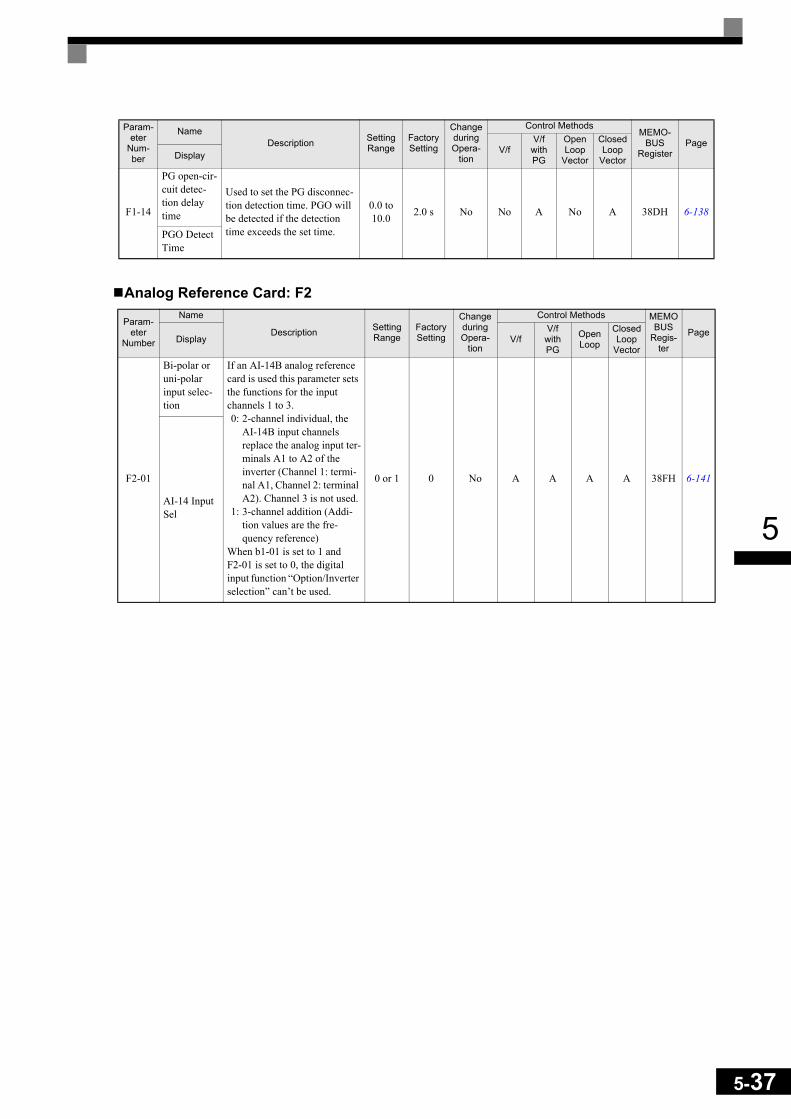
5
Analog Reference Card: F2
F1-14
PG open-cir-cuit detec-tion delay time
Used to set the PG disconnec-tion detection time. PGO will be detected if the detection time exceeds the set time.
0.0 to 10.0 2.0 s No No A No A 38DH 6-138
PGO Detect Time
Param-eter
Number
Name
Description Setting Range
Factory Setting
Change during Opera-
tion
Control Methods MEMOBUS
Regis-ter
PageDisplay V/f
V/f with PG
OpenLoop
Closed Loop
Vector
F2-01
Bi-polar or uni-polar input selec-tion
If an AI-14B analog reference card is used this parameter sets the functions for the input channels 1 to 3.0: 2-channel individual, the
AI-14B input channels replace the analog input ter-minals A1 to A2 of the inverter (Channel 1: termi-nal A1, Channel 2: terminal A2). Channel 3 is not used.
1: 3-channel addition (Addi-tion values are the fre-quency reference)
When b1-01 is set to 1 andF2-01 is set to 0, the digital input function “Option/Inverter selection” can’t be used.
0 or 1 0 No A A A A 38FH 6-141
AI-14 Input Sel
Param-eter
Num-ber
NameDescription Setting
RangeFactory Setting
Change during Opera-
tion
Control MethodsMEMO-
BUSRegister
PageV/f
V/f with PG
Open Loop
Vector
Closed Loop
VectorDisplay
5-37

5-38
5
Digital Reference Card: F3
Analog Output Option Card Setup: F4
Param-eter
Num-ber
Name
Description Setting Range
Factory Setting
Change during Opera-
tion
Control MethodsMEMOBUS
Regis-ter
PageDisplay V/f
V/f with PG
OpenLoop
Vector1
Closed Loop
Vector
F3-01
Digital input option
Sets the Digital Reference Card input method.0: BCD 1% unit1: BCD 0.1% unit2: BCD 0.01% unit3: BCD 1 Hz unit4: BCD 0.1 Hz unit5: BCD 0.01 Hz unit6: BCD special setting (5-
digit input)7: Binary input
6 is effective only, when the DI-16H2 is used.When o1-03 is set to 2 or higher, the input will be BCD, and the units will change to the o1-03 setting.
0 to 7 0 No A A A A 390H 6-141DI Input
Param-eter
NumberName Description Setting
RangeFactory Setting
Change during Opera-
tion
Control Methods MEMOBUSRegis-
ter
PageV/f
V/f with PG
Open Loop
Vector
Closed Loop
Vector
F4-01Channel 1 Monitor Selection
This function is enabled when the analog monitor card is used.
Monitor selection: Sets the number of the monitor item to be output. (Numerical portion
of U1- )4, 10, 11, 12, 13, 14, 25, 28, 35, 39 and 40 cannot be set.
Gain: Sets the percentage of the monitor item, which is equal to 10V output.
Bias: Sets the percentage of the monitor item, which is equal to 0V output.
1 to 38 2 No A A A A 391H
F4-02 Channel 1 Gain
0.0 to 100.0 100.0% Yes A A A A 392H
F4-03Channel 2 Monitor Selection
1 to 38 3 No A A A A 393H
F4-04 Channel 2 Gain
0.0 to 100.0 50.0% Yes A A A A 394H
F4-05 CH1 Output Bias
–110.0 to
110.00.0% Yes A A A A 395H
F4-06 CH2 Output Bias
–110.0 to
110.00.0% Yes A A A A 396H
F4-07Analog Out-put Signal Level CH1
Selects the analog output sig-nal level for channel 1 (effec-tive for the AO-12 option card only).
0:0 to 10V1:-10 to +10
Using an AO-08 option card the possible outputs signal is 0 to +10V only. The setting of F4-07 and F4-08 has no effect.
0, 1 0 No A A A A 397H
F4-08Analog Out-put Signal Level CH2
0, 1 0 No A A A A 398H

5
Digital Output Option Card Setup: F5Param-
eter Num-ber
Name Description Setting Range
Factory Setting
Change during Opera-
tion
Control Methods MEMOBUS
Regis-ter
PageV/f
V/f with PG
Open Loop
Vector
Closed Loop
Vector
F5-01Channel 1 Output Selection
Selects the desired multi-function output for channel 1. This function is enabled when a digital output card (DO-02 or DO-08) is used.
00 to 38 0 No A A A A 399H
F5-02Channel 2 Output Selection
Selects the desired multi-function output for channel 2. This function is enabled when a digital output card (DO-02 or DO-08) is used.
00 to 38 1 No A A A A 39AH
F5-03Channel 3 Output Selection
Selects the desired multi-function output for channel 3. This function is enabled when a digital output card (DO-02 or DO-08) is used.
0 to 38 2 No A A A A 39BH
F5-04Channel 4 Output Selection
Selects the desired multi-function output for channel 4. This function is enabled when a digital output card (DO-02 or DO-08) is used.
0 to 38 4 No A A A A 39CH
F5-05Channel 5 Output Selection
Selects the desired multi-function output for channel 5. This function is enabled when a digital output card (DO-02 or DO-08) is used.
0 to 38 6 No A A A A 39DH
F5-06Channel 6 Output Selection
Selects the desired multi-function output for channel 6. This function is enabled when a digital output card (DO-02 or DO-08) is used.
0 to 38 37 No A A A A 39EH
F5-07Channel 7 Output Selection
Selects the desired multi-function output for channel 7. This function is enabled when a digital output card (DO-02 or DO-08) is used.
0 to 38 0F No A A A A 39FH
F5-08Channel 8 Output Selection
Selects the desired multi-function output for channel 8. This function is enabled when a digital output card (DO-02 or DO-08) is used.
0 to 38 0F No A A A A 3A0H
F5-09DO-08 Out-put Mode Selection
Sets the output mode.This function is enabled when the digital output card (DO-08) is used.0:8-Channel Individual Outputs1:Binary Code Output2:Outputs according to F5-01 to
08 settings.
0 to 2 0 No A A A A 3A1H
5-39

5-40
5
Serial Communications Settings: F6Param-
eter Num-ber
NameDescription Setting
RangeFactory Setting
Change during Opera-
tion
Control MethodsMEMO-
BUSRegister
PageV/f
V/f with PG
Open Loop
Vector
Closed Loop
VectorDisplay
F6-01
Operation selection after com-munications error
Sets the stopping method for communications errors.0: Deceleration to stop using
the deceleration time in C1-02
1: Coast to stop2: Emergency stop using the
deceleration time in C1-093: Continue operation
0 to 3 1 No A A A A 3A2H -
Comm Bus Flt Sel
F6-02
Input level of external error from Communica-tions Option Card
0: Always detect1: Detect during operation 0 or 1 0 No A A A A 3A3H -
EF0 Fault Detection
F6-03
Stopping method for external error from Communica-tions Option Card
0: Deceleration to stop using the deceleration time in C1-02
1: Coast to stop2: Emergency stop using the
deceleration time in C1-093: Continue operation
0 to 3 1 No A A A A 3A4H -
EF0 Fault Action
F6-04
Trace sam-pling from Communica-tions Option Card
- 0 to 60000 0 No A A A A 3A5H -
Trace Sam-ple Tim
F6-05
Current monitor unit selection
Sets the unit of current moni-tor0: Ampere1: 100%/8192
0 or 1 0 No A A A A 3A6H -Current Unit Sel
F6-06
Torque ref-erence/torque limit selection from com-munications option card
0: Torque reference/torque limit by communications option disabled.
1: Torque reference/torque limit by communications option enabled.
0 or 1 0 No No No No A 3A7H -
Torque Ref/Lmt Sel

5
Terminal Function Parameters: H
Multi-function Digital Inputs: H1
* The values in parentheses indicate initial values when initialized in 3-wire sequence.
Multi-function Digital Input Functions
Param-eter
Num-ber
NameDescription Setting
RangeFactory Setting
Change during Opera-
tion
Control MethodsMEMO-
BUSRegister
PageV/f
V/f with PG
Open Loop
Vector
Closed Loop
VectorDisplay
H1-01
Terminal S3 function selection Multi-function input 1 0 to 78 24 No A A A A 400H -Terminal S3 Sel
H1-02
Terminal S4 function selection Multi-function input 2 0 to 78 14 No A A A A 401H -Terminal S3 Sel
H1-03
Terminal S5 function selection Multi-function input 3 0 to 78 3 (0)* No A A A A 402H -Terminal S3 Sel
H1-04
Terminal S6 function selection Multi-function input 4 0 to 78 4 (3)* No A A A A 403H -Terminal S3 Sel
H1-05
Terminal S7 function selection Multi-function input 5 0 to 78 6 (4)* No A A A A 404H -Terminal S3 Sel
Setting Value Function
Control Methods
PageV/f
V/f with PG
Open Loop Vec-tor
Closed Loop
Vector
0 3-wire sequence (Forward/Reverse Run command) Yes Yes Yes Yes 6-13
1 Local/Remote selection (ON: Operator, OFF: Parameter b1-01/b1-02 setting) Yes Yes Yes Yes 6-64
2 Operation Source Option Card/Inverter (OFF: Option Card, ON: b1-01/b1-02) Yes Yes Yes Yes 6-72
3Multi-step speed reference 1If H3-09 is set to 2, this function is combined with the master/auxiliary speed switch.
Yes Yes Yes Yes 6-10
4 Multi-step speed reference 2 Yes Yes Yes Yes 6-10
5 Multi-step speed reference 3 Yes Yes Yes Yes 6-10
6 Jog frequency command (higher priority than multi-step speed reference) Yes Yes Yes Yes 6-10
7 Accel/decel time selection 1 Yes Yes Yes Yes 6-20
8 External baseblock NO (NO contact: Baseblock at ON) Yes Yes Yes Yes 6-64
9 External baseblock NC (NC contact: Baseblock at OFF) Yes Yes Yes Yes 6-64
A Acceleration/deceleration ramp hold (ON: Acceleration/deceleration stopped, fre-quency is hold) Yes Yes Yes Yes 6-66
B OH2 alarm signal input (ON: OH2 will be displayed) Yes Yes Yes Yes 6-65
C Multi-function analog input A2 disable/enable (ON: Enable) Yes Yes Yes Yes 6-65
5-41

5-42
5
D V/f control with/without PG (ON: Speed feedback control disabled,) (normal V/f control) No Yes No No 6-37
E Speed control integral disable (ON: Integral control disabled) No Yes No Yes 6-37
F Not used (Set when a terminal is not used) - - - -
10 Up command (Always set with the Down command) Yes Yes Yes Yes 6-67
11 Down command (Always set with the Up command) Yes Yes Yes Yes 6-67
12 FJOG command (ON: Forward run at jog frequency d1-17) Yes Yes Yes Yes 6-72
13 RJOG command (ON: Reverse run at jog frequency d1-17) Yes Yes Yes Yes 6-72
14 Fault reset (Reset when turned ON) Yes Yes Yes Yes 7-2
15 Emergency stop. (NO: Deceleration to stop in deceleration time set in C1-09 when ON.) Yes Yes Yes Yes 6-18
16 Motor switch command (Motor 2 selection) Yes Yes Yes Yes 6-116
17 Emergency stop (NC: Deceleration to stop in deceleration time set in C1-09 when OFF) Yes Yes Yes Yes 6-18
18 Timer function input (Functions are set in b4-01 and b4-02 and the timer function outputs are set in H2- .) Yes Yes Yes Yes 6-95
19 PID control disable (ON: PID control disabled) Yes Yes Yes Yes 6-96
1A Accel/Decel time 2 Yes Yes Yes Yes 6-20
1B Parameters write enable (ON: All parameters can be written-in. OFF: All parame-ters are write protected.) Yes Yes Yes Yes 6-136
1C Trim control increase (ON: d4-02 frequency is added to analog frequency refer-ence.) Yes Yes Yes Yes 6-70
1D Trim control decrease (ON: d4-02 frequency is subtracted from analog frequency reference.) Yes Yes Yes Yes 6-70
1E Analog frequency reference sample/hold Yes Yes Yes Yes 6-71
20 to 2F External faultInput mode: NO contact/NC contact, Detection mode: Normal/during operation Yes Yes Yes Yes 6-66
30 PID control integral reset (reset when reset command is input or when stopped dur-ing PID control) Yes Yes Yes Yes 6-96
31 PID control integral hold (ON: Hold) Yes Yes Yes Yes 6-96
32 Multi-step speed command 4 Yes Yes Yes Yes 6-10
34 PID soft starter disable Yes Yes Yes Yes 6-96
35 PID input characteristics switch Yes Yes Yes Yes 6-96
60 DC injection braking command (ON: Performs DC injection braking) Yes Yes Yes Yes 6-17
61 External search command 1 (ON: Speed search from maximum output frequency) Yes No Yes No 6-53
62 External search command 2 (ON: Speed search from set frequency) Yes No Yes No 6-53
63 Field weakening command (ON: Field weakening control set for d6-01 and d6-02) Yes Yes No No 6-107
64 External speed search command 3 Yes Yes Yes Yes 6-53
65 Kinetic energy buffering (deceleration at momentary power loss) command (NC contact) Yes Yes Yes Yes 6-127
66 Kinetic energy buffering (deceleration at momentary power loss) command (NO contact) Yes Yes Yes Yes 6-127
67 Communications test mode Yes Yes Yes Yes 6-94
68 High-slip braking (HSB) Yes Yes No No 6-128
69 Jog Frequency 2 Yes Yes Yes Yes 6-11
6A Drive enable (NC, ON: Drive enabled, OFF: Drive disabled) Yes Yes Yes Yes 6-66
71 Speed/torque control change (ON: Torque control) No No No Yes 6-122
72 Zero-servo command (ON: Zero-servo) No No No Yes 6-125
77 Speed control (ASR) gain switching (ON: C5-03) No No No Yes 6-37
78 Polarity reversing command for external torque reference No No No Yes 6-119
Setting Value Function
Control Methods
PageV/f
V/f with PG
Open Loop Vec-tor
Closed Loop
Vector
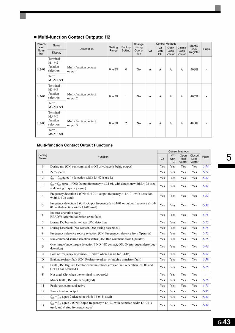
5
Multi-function Contact Outputs: H2
Multi-function Contact Output Functions
Param-eter
Num-ber
NameDescription Setting
RangeFactory Setting
Change during Opera-
tion
Control MethodsMEMO-
BUSRegister
PageV/f
V/f with PG
Open Loop
Vector
Closed Loop
VectorDisplay
H2-01
Terminal M1-M2 function selection
Multi-function contact output 1 0 to 38 0 No A A A A 40BH -
Term M1-M2 Sel
H2-02
Terminal M3-M4 function selection
Multi-function contact output 2 0 to 38 1 No A A A A 40CH -
Term M3-M4 Sel
H2-03
Terminal M5-M6 function selection
Multi-function contact output 3 0 to 38 2 No A A A A 40DH -
Term M5-M6 Sel
Setting Value Function
Control Methods
PageV/f
V/f with PG
Open loop
Vector
Closed Loop
Vector
0 During run (ON: run command is ON or voltage is being output) Yes Yes Yes Yes 6-74
1 Zero-speed Yes Yes Yes Yes 6-74
2 fref = fout agree 1 (detection width L4-02 is used.) Yes Yes Yes Yes 6-32
3fref = fset agree 1 (ON: Output frequency = ±L4-01, with detection width L4-02 used and during frequency agree)
Yes Yes Yes Yes 6-32
4 Frequency detection 1 (ON: +L4-01 ≥ output frequency ≥ -L4-01, with detection width L4-02 used) Yes Yes Yes Yes 6-32
5 Frequency detection 2 (ON: Output frequency ≥ +L4-01 or output frequency ≤ -L4-01, with detection width L4-02 used) Yes Yes Yes Yes 6-32
6 Inverter operation readyREADY: After initialization or no faults Yes Yes Yes Yes 6-75
7 During DC bus undervoltage (UV) detection Yes Yes Yes Yes 6-75
8 During baseblock (NO contact, ON: during baseblock) Yes Yes Yes Yes 6-75
9 Frequency reference source selection (ON: Frequency reference from Operator) Yes Yes Yes Yes 6-75
A Run command source selection status (ON: Run command from Operator) Yes Yes Yes Yes 6-75
B Overtorque/undertorque detection 1 NO (NO contact, ON: Overtorque/undertorque detection) Yes Yes Yes Yes 6-46
C Loss of frequency reference (Effective when 1 is set for L4-05) Yes Yes Yes Yes 6-57
D Braking resistor fault (ON: Resistor overheat or braking transistor fault) Yes Yes Yes Yes 6-59
E Fault (ON: Digital Operator communications error or fault other than CPF00 and CPF01 has occurred.) Yes Yes Yes Yes 6-75
F Not used. (Set when the terminal is not used.) Yes Yes Yes Yes -
10 Minor fault (ON: Alarm displayed) Yes Yes Yes Yes 6-75
11 Fault reset command active Yes Yes Yes Yes 6-75
12 Timer function output Yes Yes Yes Yes 6-95
13 fref = fset agree 2 (detection width L4-04 is used) Yes Yes Yes Yes 6-32
14fref = fset agree 2 (ON: Output frequency = L4-03, with detection width L4-04 is used, and during frequency agree)
Yes Yes Yes Yes 6-32
5-43

5-44
5
15 Frequency detection 3 (ON: Output frequency ≤ -L4-03, detection width L4-04 is used) Yes Yes Yes Yes 6-32
16 Frequency detection 4 (ON: Output frequency ≥ -L4-03, detection width L4-04 is used) Yes Yes Yes Yes 6-32
17 Overtorque/undertorque detection 1 NC (NC Contact, OFF: Torque detection) Yes Yes Yes Yes 6-46
18 Overtorque/undertorque detection 2 NO (NO Contact, ON: Torque detection) Yes Yes Yes Yes 6-46
19 Overtorque/undertorque detection 2 NC (NC Contact, OFF: Torque detection) Yes Yes Yes Yes 6-46
1A During reverse run (ON: During reverse run) Yes Yes Yes Yes 6-75
1B During baseblock 2 (OFF: During baseblock) Yes Yes Yes Yes 6-75
1C Motor selection (ON: Motor 2 selected) Yes Yes Yes Yes 6-76
1D During regenerative operation No No No Yes 6-76
1E Restart enabled (ON: Restart enabled) Yes Yes Yes Yes 6-58
1F Motor overload (OL1, including OH3) pre-alarm (ON: 90% or more of the detec-tion level) Yes Yes Yes Yes 6-49
20 Inverter overheat (OH) pre-alarm (ON: Temperature exceeds L8-02 setting) Yes Yes Yes Yes 6-60
30 During torque limit (current limit) (ON: During torque limit) No No Yes Yes 6-118
31 During speed limit No No No Yes 6-118
32 Activated if the speed control circuit (ASR) is operating for torque control. The ASR output becomes the torque reference. The motor is rotating at the speed limit. No No No Yes 6-118
33 Zero-servo end (ON: Zero-Servo completed) No No No Yes 6-125
37 During run 2 (ON: Frequency output, OFF: Base block, DC injection braking, ini-tial excitation, operation stop) Yes Yes Yes Yes 6-74
38 Drive enabled Yes Yes Yes Yes 6-76
Setting Value Function
Control Methods
PageV/f
V/f with PG
Open loop
Vector
Closed Loop
Vector

5
Analog Inputs: H3Param-
eter Num-ber
NameDescription Setting
RangeFactory Setting
Change during Opera-
tion
Control MethodsMEMO-
BUSRegister
PageV/f
V/f with PG
Open Loop
Vector
Closed Loop
VectorDisplay
H3-01
Multi-func-tion analog input termi-nal A1 sig-nal level selection
Sets the analog input A1 sig-nal level.0: 0 to +10V (11 bit)1: –10V to +10V (11 bit plus sign)
0 or 1 0 No A A A A 410H 6-26
Term A1 Signal
H3-02
Gain (termi-nal A1)
Sets the frequency as a per-centage of the maximum out-put frequency, when 10 V is input.
0.0 to 1000.0 100.0% Yes A A A A 411H 6-26
Terminal A1 Gain
H3-03
Bias (termi-nal A1) Sets the frequency as a per-
centage of the maximum fre-quency, when 0 V is input.
-100.0 to
+100.00.0% Yes A A A A 412H 6-26
Terminal A1 Bias
H3-08
Multi-func-tion analog input termi-nal A2 sig-nal level selection
Sets the analog input A2 sig-nal level.0: 0 to +10V (11 bit).1: –10V to +10V (11 bit plus
sign).2: 4 to 20 mA (9-bit input).
Switch current and voltage input using the switch S1 on the control terminal board.
0 to 2 2 No A A A A 417H 6-26
Term A2 Signal
H3-09
Multi-func-tion analog input termi-nal A2 func-tion selection
Selects the multi-function ana-log input function for terminal A2. Refer to the table below.If H3-13 is set to 1, H3-09 selects the function for analog input A1.
0 to 1F 0 No A A A A 418H 6-26
Terminal A2 Sel
H3-10
Gain (termi-nal A2)
Sets the input level when ter-minal A2 input is 10 V (20 mA) according to the 100% value of the function set in parameter H3-09.
0.0 to 1000.0 100.0% Yes A A A A 419H 6-26
Terminal A2 Gain
H3-11
Bias (termi-nal A2)
Sets the input level when ter-minal A2 is 0 V (4 mA) according to the 100% value of the function set in parame-ter H3-09.
-100.0 to
+100.00.0% Yes A A A A 41AH 6-26
Terminal A2 Bias
H3-12
Analog input filter time constant
Sets primary delay filter time constant for the two analog input terminals (A1 and A2).Effective for noise control etc.
0.00 to 2.00
0.03s No A A A A 41BH 6-26
Filter Avg Time
H3-13
Terminal A1/A2 switching
0: Use terminal A1 analog input as main frequency reference.
1: Use terminal A2 analog input as main frequency reference. Terminal A1 becomes multi functional. Its func-tion can be selected in parameter H3-09.
0 or 1 0 No A A A A 41CH 6-8TA1/TA2 Select
5-45

5-46
5
H3-09 Settings
Setting Value Function Contents (100%)
Control Methods
PageV/f
V/f with PG
Open Loop Vec-tor
Closed Loop
Vector
0 Frequency bias Maximum output frequency Yes Yes Yes Yes 6-27
1 Frequency gain Frequency reference (voltage) command value Yes Yes Yes Yes 6-27
2 Auxiliary frequency reference (is used as frequency reference 2) Maximum output frequency Yes Yes Yes Yes 6-7
4 Voltage bias Motor rated voltage (E1-05) Yes Yes No No -
5 Accel/decel time gain Set acceleration and deceleration times (C1-01 to C1-08) Yes Yes Yes Yes 6-21
6 DC injection braking current Inverter rated output current Yes Yes Yes No 6-18
7 Overtorque/undertorque detection level
Motor rated torque for vector controlInverter rated output current for V/f control Yes Yes Yes Yes 6-48
8 Stall prevention level during run Inverter rated output current Yes Yes No No 6-45
9 Frequency reference lower limit level Maximum output frequency Yes Yes Yes Yes 6-30
A Jump frequency Maximum output frequency Yes Yes Yes Yes 6-29
B PID feedback Maximum output frequency Yes Yes Yes Yes 6-96
C PID target value Maximum output frequency Yes Yes Yes Yes 6-96
D Frequency bias 2 Maximum output frequency Yes Yes Yes Yes
E Motor temperature input – Yes Yes Yes Yes 6-50
10 Positive torque limit Motor's rated torque No No Yes Yes 6-43
11 Negative torque limit Motor's rated torque No No Yes Yes 6-43
12 Regenerative torque limit Motor's rated torque No No Yes Yes 6-43
13 Torque reference/torque limit at speed control Motor’s rated torque No No No Yes 6-118
14 Torque compensation Motor’s rated torque No No No Yes 6-118
15 Positive/negative torque limit Motor's rated torque No No Yes Yes 6-43
1F Analog input not used. – Yes Yes Yes Yes –

5
Multi-function Analog Outputs: H4Param-
eter Num-ber
NameDescription Setting
RangeFactory Setting
Change during Opera-
tion
Control MethodsMEMO-
BUSRegister
PageV/f
V/f with PG
Open Loop
Vector
Closed Loop
VectorDisplay
H4-01
Monitor selection (terminal FM)
Sets the number of the moni-tor item to be output (U1-
) at terminal FM.The monitors U1-04, -10 to -14, -28, -34, -39, -40 cannot be set to output at terminal FM)
1 to 38 2 No A A A A 41DH 6-77
Terminal FM Sel
H4-02
Gain (termi-nal FM)
Sets the multi-function analog output 1 (terminal FM) gain.Sets the percentage of the monitor item that is equal to 10V/20mA output at terminal FM. Note that the maximum output voltage/current is 10V/20mA.
0 to 1000.0
%100% Yes Q Q Q Q 41EH 4-5
6-77Terminal FM Gain
H4-03
Bias (termi-nal FM)
Sets the multi-function analog output 1 (terminal FM) bias.Sets the percentage of the monitor item that is equal to 0V/4mA output at terminal FM.The maximum output from the terminal is 10 V/20mA.
-110 to +110% 0.0% Yes A A A A 41FH 6-77
Terminal FM Bias
H4-04
Monitor selection (terminal AM)
Sets the number of the moni-tor item to be output (U1-
) at terminal AM.The monitors U1-04, -10 to -14, -28, -34, -39, -40 cannot be set to be output at terminal AM).
1 to 38 3 No A A A A 420H 6-77
Terminal AM Sel
H4-05
Gain (termi-nal AM)
Set the multi-function analog output 2 (terminal AM) gain.Sets the percentage of the monitor item that is equal to 10V/20mA output at terminal AM. Note that the maximum output voltage/current is 10V/20mA.
0 to 1000.0
%50.0% Yes Q Q Q Q 421H 4-5
6-77Terminal AM Gain
H4-06
Bias (termi-nal AM)
Sets the multi-function analog output 2 (terminal AM) bias.Sets the percentage of the monitor item that is equal to 0V/4mA output at terminal AM.The maximum output from the terminal is 10 V/20mA.
-110.0 to
+110.0%
0.0% Yes A A A A 422H 6-77Terminal AM Bias
H4-07
Analog out-put 1 signal level selec-tion
Sets the signal output level for multi-function output 1 (ter-minal FM)0: 0 to +10 V output1: –10V to +10V output2: 4 – 20 mASwitch current and voltage
output using CN15 on the control panel
0 to 2 0 No A A A A 423H 6-77
AO Level Select1
5-47

5-48
5
MEMOBUS Communications: H5
* Set H5-01 to 0 to disable Inverter responses to MEMOBUS communications.
H4-08
Analog out-put 2 signal level selec-tion
Sets the signal output level for multi-function output 2 (ter-minal AM)0: 0 to +10 V output1: –10V to +10V output2: 4 – 20 mASwitch current and voltage
output using CN15 on the control panel
0 to 2 0 No A A A A 424H 6-77
AO Level Select2
Param-eter
Num-ber
NameDescription Setting
RangeFactory Setting
Change during Opera-
tion
Control MethodsMEMO-
BUSRegister
PageV/f
V/f with PG
Open Loop
Vector
Closed Loop
VectorDisplay
H5-01
Station address Sets the Inverter's node
address.0 to 20
* 1F No A A A A 425H 6-80Serial Comm Adr
H5-02
Communica-tions speed selection
Sets the baud rate for MEMO-BUS communications.0: 1200 bps1: 2400 bps2: 4800 bps3: 9600 bps4: 19200 bps
0 to 4 3 No A A A A 426H 6-80Serial Baud Rate
H5-03
Communica-tions parity selection
Sets the parity for MEMO-BUS communications.0: No parity1: Even parity2: Odd parity
0 to 2 0 No A A A A 427H 6-80Serial Com Sel
H5-04
Stopping method after communica-tions error
Sets the stopping method for communications errors.0: Deceleration to stop using
the deceleration time in C1-02
1: Coast to stop2: Emergency stop using the
deceleration time in C1-093: Continue operation
0 to 3 3 No A A A A 428H 6-80
Serial Fault Sel
H5-05
Communica-tions error detection selection
Sets whether or not a commu-nications time-out is to be detected as a communications error.0: Do not detect.1: Detect
0 or 1 1 No A A A A 429H 6-80
Serial Flt Dtct
H5-06
Send wait time Sets the time from the Inverter
receiving data to when the Inverter starts to send.
5 to 65 5 ms No A A A A 42AH 6-80Transmit WaitTIM
H5-07
RTS control ON/OFF
Enables or disables RTS con-trol.0: Disabled (RTS is always
ON)1: Enabled (RTS turns ON
only when sending)
0 or 1 1 No A A A A 42BH 6-80RTS Con-trol Sel
Param-eter
Num-ber
NameDescription Setting
RangeFactory Setting
Change during Opera-
tion
Control MethodsMEMO-
BUSRegister
PageV/f
V/f with PG
Open Loop
Vector
Closed Loop
VectorDisplay

5
Pulse Train I/O: H6Param-
eter Num-ber
NameDescription Setting
RangeFactory Setting
Change during Opera-
tion
Control MethodsMEMO-
BUSRegister
PageV/f
V/f with PG
Open Loop
Vector
Closed Loop
VectorDisplay
H6-01
Pulse train input func-tion selec-tion
Selects the pulse train input function0: Frequency reference1: PID feedback value2: PID target value
0 to 2 0 No A A A A 42CH 6-76-29
Pulse Input Sel
H6-02
Pulse traininput scaling
Sets the number of pulses in Hertz, that is equivalent to 100% of the input item selected in H6-01.
1000 to 32000
1440 Hz Yes A A A A 42DH 6-7
6-29Pulse In Scaling
H6-03
Pulse train input gain
Sets the input level according to 100% of the input item selected in H6-01, when a pulse train with the frequency set in H6-02 is input.
0.0 to 1000.0 100.0% Yes A A A A 42EH 6-29
Pulse Input Gain
H6-04
Pulse train input bias
Sets the input level according to 100% of the input item selected in H6-01, when the pulse train frequency is 0.
-100.0 to
100.00.0% Yes A A A A 42FH 6-29
Pulse Input Bias
H6-05
Pulse train input filter time Sets the pulse train input delay
filter time constant in seconds.0.00 to
2.000.10
s Yes A A A A 430H 6-29Pulse In Filter
H6-06
Pulse train monitor selection
Select the pulse train monitor output items (value of the part of U1- ).There are two types of moni-tor items: Speed-related items and PID-related items.
1, 2, 5, 20, 24,
362 Yes A A A A 431H 6-78
Pulse Moni Sel
H6-07
Pulse Moni Scaling
Sets the number of pulses out-put in hertz when the monitor item is 100%.Sets H6-06 to 2, and H6-07 to 0, to make the pulse train monitor output synchronously to the output frequency.
0 to 32000
1440 Hz Yes A A A A 432H 6-78
PO Scaling
5-49

5-50
5
Protection Function Parameters: L
Motor Overload: L1Param-
eter Num-ber
NameDescription Setting
RangeFactory Setting
Change during Opera-
tion
Control MethodsMEMO-
BUSRegister
PageV/f
V/f with PG
Open Loop
Vector
Closed Loop
VectorDisplay
L1-01
Motor pro-tection selection
Sets whether the motor thermal overload protection function is enabled or disabled.0: Disabled1: General-purpose motor
protection (fan cooled motor)
2: Inverter motor protection (externally cooled motor)
3: Vector motor protectionWhen the Inverter power supply is turned off, the thermal value is reset, so even if this parameter is set to 1, protection may not be effective.
When several motors are con-nected to one Inverter, set to L1-01 to 0 and ensure that each motor is installed with a pro-tection device.
0 to 3 1 No Q Q Q Q 480H 4-56-48
MOL Fault Select
L1-02
Motor pro-tection time constant
Sets the electric thermal detec-tion time in seconds units.Usually changing this setting is not necessary.The factory setting is 150% overload for one minute. When the motor's overload capability is known, also set the overload resistance protec-tion time for when the motor is hot started.
0.1 to5.0 1.0 min No A A A A 481H 6-48
MOL Time Const
L1-03
Alarm oper-ation selec-tion during motor over-heating
Selects the operation when the input motor temperature (ther-mistor) input exceeds the alarm detection level (1.17 V) (H3-09 must be set to E).0: Decelerate to stop1: Coast to stop2: Emergency stop using the
deceleration time in C1-09.3: Continue operation (oH3
on the Operator flashes).
0 to 3 3 No A A A A 482H 6-50
Mtr OH Alarm Sel
L1-04
Motor over-heating operation selection
Selects the operation when the motor temperature (ther-mistor) input exceeds the over-heating detection level (2.34 V) (H3-09 must be set to E).0: Decelerate to stop1: Coast to stop2: Emergency stop using the
deceleration time in C1-09.
0 to 2 1 No A A A A 483H 6-50
Mtr OH Fault Sel

5
Power Loss Ride Through: L2
L1-05
Motor tem-perature input filter time con-stant
Sets H3-09 to E and sets the delay time constant for the motor temperature (ther-mistor) input in seconds.
0.00 to10.00 0.20 s No A A A A 484H 6-50
Mtr Temp Filter
Param-eter
Num-ber
NameDescription Setting
RangeFactory Setting
Change during Opera-
tion
Control MethodsMEMO-
BUSRegister
PageV/f
V/f with PG
Open Loop
Vector
Closed Loop
VectorDisplay
L2-01
Momentary power loss detection
0: Disabled (DC bus undervoltage (UV1) detec-tion)
1: Enabled (Restarted when the power returns within the time set in L2-02. When L2-02 is exceeded, DC bus undervoltage is detected.)
2: Enabled while CPU is operating. (Restarts when power returns during control operations. Does not detect DC bus undervoltage.)
0 to 2 0 No A A A A 485H 6-526-127
PwrL Selec-tion
L2-02
Momentary power loss ride through time
Ridethrough time, when Momentary Power Loss Selec-tion (L2-01) is set to 1, in units of seconds.
0 to 25.5
0.1 s*1 No A A A A 486H 6-52
PwrL Ride-thru t
L2-03
Min. base-block time
Sets the Inverter's minimum baseblock time, when the Inverter is restarted after power loss ride through.Set the time to approximately 0.7 times the motor time con-stant.When an overcurrent or over-voltage occurs when starting a speed search or DC injection braking, increase the set val-ues.
0.1 to 5.0
0.2 s*1 No A A A A 487H 6-52
6-53PwrL Base-block t
L2-04
Voltage recovery time
Sets the time required to return the Inverter output voltage from 0V to normal voltage at the completion of a speed search.
0.0 to5.0
0.3 s*1 No A A A A 488H 6-52
6-53PwrL V/F Ramp t
L2-05
Undervolt-age detec-tion level
Sets the DC bus undervoltage (UV) detection level (DC bus voltage).Usually changing this setting is not necessary.
150 to210*2
190 V*2 No A A A A 489H 6-52
6-127PUV Det Level
Param-eter
Num-ber
NameDescription Setting
RangeFactory Setting
Change during Opera-
tion
Control MethodsMEMO-
BUSRegister
PageV/f
V/f with PG
Open Loop
Vector
Closed Loop
VectorDisplay
5-51
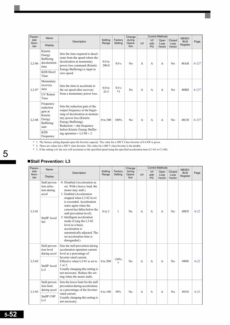
5-52
5
* 1. The factory setting depends upon the Inverter capacity. The value for a 200 V Class Inverter of 0.4 kW is given.* 2. These are values for a 200 V class Inverter. The value for a 400 V class Inverter is the double.* 3. If the setting is 0, the axis will accelerate to the specified speed using the specified acceleration time (C1-01 to C1-08).Stall Prevention: L3
L2-06
Kinetic Energy Buffering deceleration time
Sets the time required to decel-erate from the speed where the deceleration at momentary power loss command (Kinetic Energy Buffering) is input to zero speed.
0.0 to200.0 0.0 s No A A A No 48AH 6-127
KEB Decel Time
L2-07
Momentary recovery time
Sets the time to accelerate to the set speed after recovery from a momentary power loss.
0.0 to25.5
0.0 s*3 No A A A No 48BH 6-127
UV Return Time
L2-08
Frequency reduction gain at Kinetic Energy Buffering start
Sets the reduction gain of the output frequency at the begin-ning of deceleration at momen-tary power loss (Kinetic Energy Buffering).Reduction = slip frequency before Kinetic Energy Buffer-ing operation × L2-08 × 2
0 to 300 100% No A A A No 48CH 6-127
KEB Frequency
Param-eter
Num-ber
NameDescription Setting
RangeFactory Setting
Change during Opera-
tion
Control MethodsMEMO-
BUSRegister
PageV/f
V/f with PG
Open Loop
Vector
Closed Loop
VectorDisplay
L3-01
Stall preven-tion selec-tion during accel
0: Disabled (Acceleration as set. With a heavy load, the motor may stall.)
1: Enabled (Acceleration stopped when L3-02 level is exceeded. Acceleration starts again when the current has fallen below the stall prevention level).
2: Intelligent acceleration mode (Using the L3-02 level as a basis, acceleration is automatically adjusted. The set acceleration time is disregarded.)
0 to 2 1 No A A A No 48FH 6-22
StallP Accel Sel
L3-02
Stall preven-tion level during accel
Sets the stall prevention during acceleration operation current level as a percentage of Inverter rated current.Effective when L3-01 is set to 1 or 2.Usually changing this setting is not necessary. Reduce the set-ting when the motor stalls.
0 to 200 150%* No A A A No 490H 6-22
StallP Accel Lvl
L3-03
Stall preven-tion limit during accel
Sets the lower limit for the stall prevention during acceleration, as a percentage of the Inverter rated current.Usually changing this setting is not necessary.
0 to 100 50% No A A A No 491H 6-22StallP CHP Lvl
Param-eter
Num-ber
NameDescription Setting
RangeFactory Setting
Change during Opera-
tion
Control MethodsMEMO-
BUSRegister
PageV/f
V/f with PG
Open Loop
Vector
Closed Loop
VectorDisplay

5
* The given initial value is valid if Heavy Duty is selected (C6-01=0, default setting). If Normal Duty 1 or 2 is selected (C6-01=1 or 2) the initial value will be 120%.
L3-04
Stall preven-tion selec-tion during decel
Selects the stall prevention during deceleration.0: Disabled (Deceleration as
set. If deceleration time is too short, a DC-Bus overvoltage may result.)
1: Enabled (Deceleration is stopped when the DC-Bus voltage exceeds the stall prevention level. Deceleration restarts when the voltage falls below the stall prevention level again.)
2: Intelligent deceleration mode (Deceleration rate is automatically adjusted so that in Inverter can decelerate in the shortest possible time. The set deceleration time is disregarded.)
3: Enabled (with Braking Resistor Unit)
When a braking option (Brak-ing Resistor, Braking Resistor Unit, Braking Unit) is used, always set to 0 or 3.
0 to 3 1 No Q Q Q Q 492H 4-56-24
StallP Decel Sel
L3-05
Stall preven-tion selec-tion during running
Selects the stall prevention during running.0: Disabled (Runs as set. With
a heavy load, the motor may stall.)
1: Deceleration using deceleration time 1(C1-02.)
2: Deceleration using deceler-ationtime 2 (C1-04.)
0 to 2 1 No A A No No 493H 6-45
StallP Run Sel
L3-06
Stall preven-tion level during run-ning
Set the stall prevention during running operation current level as a percentage of the Inverter rated current.Effective when L3-05 is 1 or 2.Usually changing this setting is not necessary.Reduce the setting when the motor stalls.
30 to 200
150%* No A A No No 494H 6-45
StallP Run Level
Param-eter
Num-ber
NameDescription Setting
RangeFactory Setting
Change during Opera-
tion
Control MethodsMEMO-
BUSRegister
PageV/f
V/f with PG
Open Loop
Vector
Closed Loop
VectorDisplay
5-53

5-54
5
Reference Detection: L4
* The given setting range is valid if Heavy Duty is selected (C6-01=0, default setting). If Normal Duty 1 or 2 is selected (C6-01=1 or 2) the setting range will be 0.0 to 400.0 Hz.
Fault Restart: L5
Parameter
Num-ber
NameDescription Setting
RangeFactory Setting
Change during Opera-
tion
Control MethodsMEMO-
BUSRegister
PageV/f
V/f with PG
Open Loop
Vector
Closed Loop
VectorDisplay
L4-01
Speed agree-ment detection level
Effective when "fout = fset agree 1", "Frequency detec-tion 1" or "Frequency detec-tion 2" is set for a multi-function output.
0.0 to 150.0
*0.0 Hz No A A A A 499H 6-31
Spd Agree Level
L4-02
Speed agree-ment detection width
Effective when "fref = fout agree 1", "fout = fset agree 1" or "Frequency detection 1" or "Frequency detection 2" is set for a multi-function output.
0.0 to 20.0 2.0 Hz No A A A A 49AH 6-31
Spd Agree Width
L4-03
Speed agree-ment detection level (+/-)
Effective when "fout = fset agree 2", "Frequency detec-tion 3" or "Frequency detec-tion 4" is set for a multi-function output.
-150.0 to
+150.0*
0.0 Hz No A A A A 49BH 6-31Spd Agree Lvl+-
L4-04
Speed agree-ment detection width (+/-)
Effective when "fref = fout agree 2" "fout = fset agree 2", "Frequency detection 3" or "Frequency detection 4" is set for a multi-function output.
0.0 to 20.0 2.0 Hz No A A A A 49CH 6-31
Spd Agree Wdth+-
L4-05
Operation when fre-quency refer-ence is missing
0: Stop (Operation follows the frequency reference.)
1: Operation continues at the frequency, set in parameter L4-06.
Frequency reference loss means that the frequency reference value drops over 90% in 400 ms.
0 or 1 0 No A A A A 49DH 6-57
Ref Loss Sel
L4-06
Frequency ref-erence value at frequency reference loss
Sets the frequency reference value when the frequency ref-erence is missing
0.0 to 100.0% 80% No A A A A 4C2H 6-57
Fref at Floss
Param-eter
Num-ber
NameDescription Setting
RangeFactory Setting
Change during Opera-
tion
Control MethodsMEMO-
BUSRegister
PageV/f
V/f with PG
Open Loop
Vector
Closed Loop
VectorDisplay
L5-01
Number of auto restart attempts
Sets the number of auto restart attempts.Automatically restarts after a fault and conducts a speed search from the run frequency.
0 to 10 0 No A A A A 49EH 6-58Num of Restarts
L5-02
Auto restart operation selection
Sets whether a fault contact output is activated during fault restart.0: No output (Fault contact is
not activated.)1: Output (Fault contact is
activated.)
0 or 1 0 No A A A A 49FH 6-58
Restart Sel

5
Torque Detection: L6Param-
eter Num-ber
NameDescription Setting
RangeFactory Setting
Change during Opera-
tion
Control MethodsMEMO-
BUSRegister
PageV/f
V/f with PG
Open Loop
Vector
Closed Loop
VectorDisplay
L6-01
Torque detection selection 1
0: Overtorque/undertorque detection disabled.
1: Overtorque detection only with speed agreement; operation continues (warning is output).
2: Overtorque detected continuously during operation; operation continues (warning is output).
3: Overtorque detection only with speed agreement; output stopped upon detection.
4: Overtorque detected continuously during operation; output stopped upon detection.
5: Undertorque detection only with speed agree-ment; operation continues (warning is output).
6: Undertorque detected continuously during operation; operation continues (warning is output).
7: Undertorque detection only with speed agree-ment; output stopped upon detection.
8: Undertorque detected continuously during operation; output stopped upon detection.
0 to 8 0 No A A A A 4A1H 6-46
Torq Det 1 Sel
L6-02
Torque detec-tion level 1
Vector control: Motor rated torque is set as 100%.V/f control: Inverter rated cur-rent is set as 100%.
0 to 300 150% No A A A A 4A2H 6-46
Torq Det 1 Lvl
L6-03
Torque detec-tion time 1 Sets the overtorque/under-
torque detection time.0.0 to 10.0 0.1 s No A A A A 4A3H 6-46
Torq Det 1 Time
L6-04
Torque detec-tion selection 2
See L6-01 to L6-03 for a description.
0 to 8 0 No A A A A 4A4H 6-46
Torq Det 2 Sel
L6-05
Torque detec-tion level 2 0 to
300 150% No A A A A 4A5H 6-46Torq Det 2 Lvl
L6-06
Torque detec-tion time 2 0.0 to
10.0 0.1 s No A A A A 4A6H 6-46Torq Det 2 Time
5-55
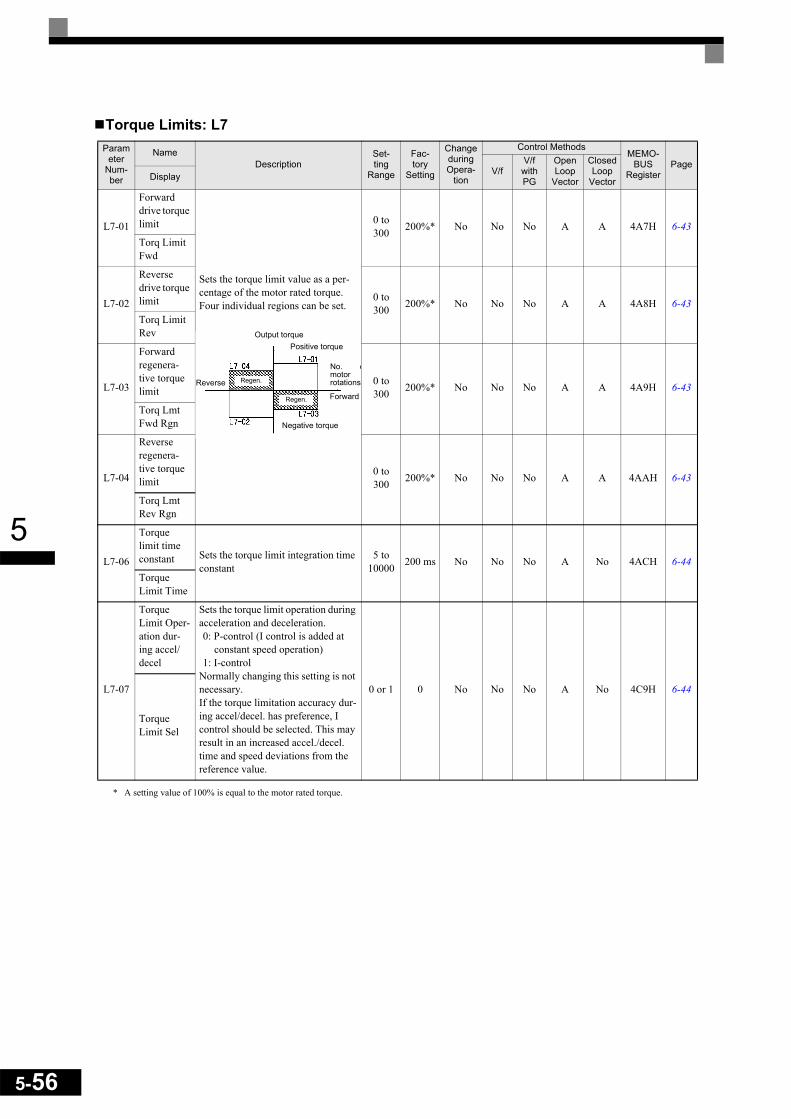
5-56
5
Torque Limits: L7
* A setting value of 100% is equal to the motor rated torque.
Parameter
Num-ber
NameDescription
Set-ting
Range
Fac-tory
Setting
Change during Opera-
tion
Control MethodsMEMO-
BUSRegister
PageV/f
V/f with PG
Open Loop
Vector
Closed Loop
VectorDisplay
L7-01
Forward drive torque limit
Sets the torque limit value as a per-centage of the motor rated torque.Four individual regions can be set.
0 to 300 200%* No No No A A 4A7H 6-43
Torq Limit Fwd
L7-02
Reverse drive torque limit 0 to
300 200%* No No No A A 4A8H 6-43Torq Limit Rev
L7-03
Forward regenera-tive torque limit
0 to 300 200%* No No No A A 4A9H 6-43
Torq Lmt Fwd Rgn
L7-04
Reverse regenera-tive torque limit
0 to 300 200%* No No No A A 4AAH 6-43
Torq Lmt Rev Rgn
L7-06
Torque limit time constant Sets the torque limit integration time
constant5 to
10000 200 ms No No No A No 4ACH 6-44Torque Limit Time
L7-07
Torque Limit Oper-ation dur-ing accel/decel
Sets the torque limit operation during acceleration and deceleration.0: P-control (I control is added at
constant speed operation)1: I-control
Normally changing this setting is not necessary. If the torque limitation accuracy dur-ing accel/decel. has preference, I control should be selected. This may result in an increased accel./decel. time and speed deviations from the reference value.
0 or 1 0 No No No A No 4C9H 6-44
Torque Limit Sel
Output torquePositive torque
Reverse
Negative torque
No. omotorrotationsRegen.
ForwardRegen.
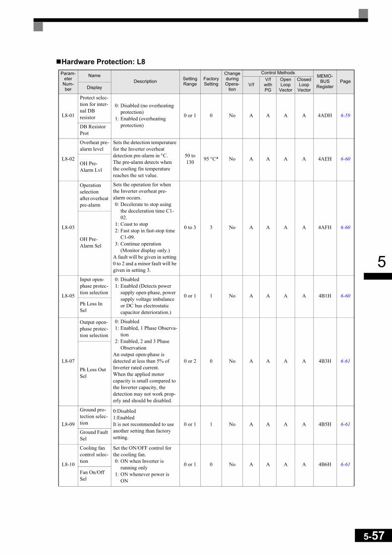
5
Hardware Protection: L8Param-
eter Num-ber
NameDescription Setting
RangeFactory Setting
Change during Opera-
tion
Control MethodsMEMO-
BUSRegister
PageV/f
V/f with PG
Open Loop
Vector
Closed Loop
VectorDisplay
L8-01
Protect selec-tion for inter-nal DB resistor
0: Disabled (no overheating protection)
1: Enabled (overheating protection)
0 or 1 0 No A A A A 4ADH 6-59
DB Resistor Prot
L8-02
Overheat pre-alarm level
Sets the detection temperature for the Inverter overheat detection pre-alarm in °C.The pre-alarm detects when the cooling fin temperature reaches the set value.
50 to 130 95 °C* No A A A A 4AEH 6-60
OH Pre-Alarm Lvl
L8-03
Operation selection after overheat pre-alarm
Sets the operation for when the Inverter overheat pre-alarm occurs.0: Decelerate to stop using
the deceleration time C1-02.
1: Coast to stop 2: Fast stop in fast-stop time
C1-09.3: Continue operation
(Monitor display only.)A fault will be given in setting 0 to 2 and a minor fault will be given in setting 3.
0 to 3 3 No A A A A 4AFH 6-60
OH Pre-Alarm Sel
L8-05
Input open-phase protec-tion selection
0: Disabled1: Enabled (Detects power
supply open-phase, power supply voltage imbalance or DC bus electrostatic capacitor deterioration.)
0 or 1 1 No A A A A 4B1H 6-60Ph Loss In Sel
L8-07
Output open-phase protec-tion selection
0: Disabled1: Enabled, 1 Phase Observa-
tion 2: Enabled, 2 and 3 Phase
ObservationAn output open-phase is detected at less than 5% of Inverter rated current.When the applied motor capacity is small compared to the Inverter capacity, the detection may not work prop-erly and should be disabled.
0 or 2 0 No A A A A 4B3H 6-61Ph Loss Out Sel
L8-09
Ground pro-tection selec-tion
0:Disabled1:Enabled It is not recommended to use another setting than factory setting.
0 or 1 1 No A A A A 4B5H 6-61Ground Fault Sel
L8-10
Cooling fan control selec-tion
Set the ON/OFF control for the cooling fan.0: ON when Inverter is
running only1: ON whenever power is
ON
0 or 1 0 No A A A A 4B6H 6-61Fan On/Off Sel
5-57

5-58
5
* The factory setting depends upon the Inverter capacity. The value for a 200 V Class Inverter of 0.4 kW is given.
N: Special Adjustments
Hunting Prevention Function: N1
L8-11
Cooling fan control delay time
Set the time in seconds to delay turning OFF the cooling fan after the inverter STOP command is given.
0 to 300 60 s No A A A A 4B7H 6-61Fan Delay Time
L8-12
Ambient temperature
Sets the ambient temperature. 45 to 60 45 °C No A A A A 4B8H 6-62Ambient Temp
L8-15
OL2 charac-teristics selection at low speeds
0: OL2 characteristics at low speeds disabled.
1: OL2 characteristics at low speeds enabled.
It is not recommended to use another setting than the fac-tory setting.
0 or 1 1 No A A A A 4BBH 6-63
OL2 Sel @ L-Spd
L8-18
Soft CLA selection 0: Disable
1: Enable 0 or 1 0 No A A A A 4BFH -Soft CLA Sel
Param-eter
Num-ber
NameDescription Setting
RangeFactory Setting
Change during Opera-
tion
Control MethodsMEMO-
BUSRegister
PageV/f
V/f with PG
Open Loop
Vector
Closed Loop
VectorDisplay
N1-01
Hunting-pre-vention function selection
0: Hunting-prevention function disabled
1: Hunting-prevention function enabled
The hunting-prevention func-tion suppresses hunting when the motor is operating with a light load.If high response has the prior-ity over vibration suppres-sion, disable the hunting-prevention function.
0 or 1 1 No A A No No 580H 6-41
Hunt Prev Select
N1-02
Hunting-pre-vention gain
Sets the hunting-prevention gain.Normally, there is no need to change this setting.If necessary, make the adjust-ments as follows:• If vibration occurs with
light load, increase the set-ting.
• If the motor stalls, reduce the setting.
If the setting is too large, the voltage will be too suppressed and the motor may stall.
0.00 to 2.50 1.00 No A A No No 581H 4-14
6-41Hunt Prev Gain
Param-eter
Num-ber
NameDescription Setting
RangeFactory Setting
Change during Opera-
tion
Control MethodsMEMO-
BUSRegister
PageV/f
V/f with PG
Open Loop
Vector
Closed Loop
VectorDisplay

5
Automatic Frequency Regulator: N2
High-slip Braking: N3
Param-eter
Num-ber
Name Description Setting Range
Factory Setting
Change during Opera-
tion
Control MethodsMEMO-
BUSRegister
PageV/f
V/f with PG
Open Loop
Vector
Closed Loop
Vector
N2-01
Speed feed-back detec-tion control (AFR) gain
Sets the internal speed feed-back detection control gain.Normally, there is no need to change this setting.If necessary, adjust this parameter as follows:• If hunting occurs, increase
the set value.• If response is low, decrease
the set value.Adjust the setting by 0.05 at a time, while checking the response.
0.00 to 10.00 1.00 No No No A No 584H 4-14
6-42
AFR Gain
N2-02
Speed feed-back detec-tion control (AFR) time constant
Set the time constant 1 to decide the rate of change in the speed feedback detection control.
0 to 2000 50 ms No No No A No 585H 6-42
AFR Time
N2-03
Speed feed-back detec-tion control (AFR) time constant 2
Set the time constant 2 to decide the rate of change in the speed.
0 to 2000 750 ms No No No A No 586H 6-42
AFR Time 2
Param-eter
Num-ber
NameDescription Setting
RangeFactory Setting
Change during Opera-
tion
Control MethodsMEMO-
BUSRegister
PageV/f
V/f with PG
Open Loop
Vector
Closed Loop
VectorDisplay
N3-01
High-slip braking deceleration frequency width
Sets the frequency width for deceleration during high-slip braking in percent, taking the maximum frequency (E1-04) as 100%.
1 to 20 5% No A A No No 588H 6-128
HSB Down Freq
N3-02
High-slip braking cur-rent limit
Sets the current limit for deceleration during high-slip braking in percent, taking the motor rated current as 100%. The resulting limit must be 150% of the Inverter rated current or less.
100 to 200 150% No A A No No 589H 6-128
HSB Current
N3-03
High-slip braking stop dwell time
Sets the dwell time of the out-put frequency for FMIN (1.5 Hz) during V/f control.Effective only during deceler-ation with high-slip braking.
0.0 to 10.0 1.0 s No A A No No 58AH 6-128
HSB Dwell Time
N3-04
High-slip braking OL time
Set the OL time when the out-put frequency does not change for any reason during deceler-ation with high-slip braking.
30 to 1200 40 s No A A No No 58BH 6-128
HSB OL Time
5-59

5-60
5
Digital Operator Parameters: o
Monitor Selections: o1Param-
eter Num-ber
NameDescription Setting
RangeFactory Setting
Change during Opera-
tion
Control MethodsMEMO-
BUSRegister
PageV/f
V/f with PG
Open Loop
Vector
Closed Loop
VectorDisplay
o1-01
Monitor selection
Set the number of the 4rd. monitor item to be displayed in the Drive Mode. (U1- )(On LED operator only.)
4 to 33 6 Yes A A A A 500H 6-130User Moni-tor Sel
o1-02
Monitor selection after power up
Sets the monitor item to be displayed when the power is turned on.1: Frequency reference2: Output frequency3: Output current4: The monitor item set for
o1-01
1 to 4 1 Yes A A A A 501H 6-130
Power-On Monitor
o1-03
Frequency units of ref-erence set-ting and monitor
Sets the units that will be set and displayed for the fre-quency reference and fre-quency monitor.0: 0.01 Hz units1: 0.01% units
(Maximum output frequency is 100%)
2 to 39: rpm units (Set the motor poles.)
40 to 39999: User desired display Set the desired values for setting and display for the max. output frequency.
Example: When the max. out-put frequency value is 200.0, set 12000
0 to 39999 0 No A A A A 502H 6-131
Display Scaling
o1-04
Setting unit for fre-quency parameters related to V/f characteris-tics
Set the setting unit for fre-quency reference-related parameters.0: Hz1: min−1
0 or 1 0 No No No No A 503H 6-131
V/f Display Unit
o1-05
LCD Dis-play contrastadjustment
Sets the contrast on the optional LCD operator (JVOP-160).1: light2:3: normal4:5: dark
0 to 5 3 Yes A A A A 504H 6-131LCD Con-trast
Sets the value that is to be displayed at 100% excluding the decimal point.
Sets the number of decimal places.

5
Digital Operator Functions: o2Param-
eter Num-ber
NameDescription Setting
RangeFactory Setting
Change during Opera-
tion
Control MethodsMEMO-
BUSRegister
PageV/f
V/f with PG
Open Loop
Vector
Closed Loop
VectorDisplay
o2-01
LOCAL/REMOTE key enable/disable
Enables/Disables the Digital Operator Local/Remote key0: Disabled1: Enabled (Switches
between the Digital Operator and the parame-ter settings b1-01, b1-02.)
0 or 1 1 No A A A A 505H 6-131
Local/Remote Key
o2-02
STOP key during con-trol circuit terminal operation
Enables/Disables the Stop key in the run mode.0: Disabled (When the run
command is issued from an external terminal, the Stop key is disabled.)
1: Enabled (Effective even during run.)
0 or 1 1 No A A A A 506H 6-131
Oper Stop Key
o2-03
User param-eter initial value
Clears or stores user initial values.0: Stores/not set1: Begins storing (Records
the set parameters as user initial values.)
2: All clear (Clears all recorded user initial values)
When the set parameters are recorded as user initial val-ues, 1110 will be set in A1-03.
0 to 2 0 No A A A A 507H 6-131
User Defaults
o2-04
kVA selec-tion
Do not set unless after replac-ing the control board. (Refer to page 5-72 for the setting values).
0 to FF 0 No A A A A 508H 6-131Inverter Model #
o2-05
Frequency reference setting method selection
When the frequency reference is set on the Digital Operator frequency reference monitor, sets whether the Enter key is necessary or not.0: Enter key needed1: Enter key not needed
When set to 1, the Inverter accepts the frequency refer-ence without Enter key opera-tion.
0 or 1 0 No A A A A 509H 6-131
Operator M.O.P.
o2-06
Operation selection when digital operator is disconnected
Sets the operation when the Digital Operator is discon-nected.0: Operation continues even
if the Digital Operator is disconnected.
1: OPR is detected at Digital Operator disconnection. Inverter output is switched off, and the fault contact is operated.
0 or 1 0 No A A A A 50AH 6-131
Oper Detection
o2-07
Cumulative operation time setting Sets the cumulative operation
time in hour units.0 to
65535 0 hr No A A A A 50BH 6-132Elapsed Time Set
5-61

5-62
5
Copy Function: o3o2-08
Cumulative operation time selec-tion
0: Accumulated inverter power on time.
1: Accumulated inverter run time.
0 or 1 1 No A A A A 50CH 6-132
Elapsed Time Run
o2-09
Initialize Mode 2: Europe 2 2 No A A A A 50DH -InitModeSet
o2-10
Fan opera-tion time set-ting
Sets the initial value of the fan operation time.The operation time is accumu-lated starting from this set value.
0 to 65535 0 hr No A A A A 50EH 6-132
Fan ON Time Set
o2-12
Fault trace initialize
0: No initialisation1: Initialize (= zero clear) after setting ”1“ o2-12 will be returned to ”0“
0 or 1 0 No A A A A 510H 6-132Fault Trace Init
o2-14
kWh moni-tor initialize
0: No initialisation1: Initialize (= zero clear) after setting ”1“ o2-14 will be returned to ”0“
0 or 1 0 No A A A A 512H 6-132kWh Moni-tor Init
Param-eter
Num-ber
NameDescription Setting
RangeFactory Setting
Change during Opera-
tion
Control MethodsMEMO-
BUSRegister
PageV/f
V/f with PG
Open Loop
Vector
Closed Loop
VectorDisplay
o3-01
Copy func-tion selec-tion
0: Normal operation1: READ (Inverter to
Operator)2: COPY (Operator to
Inverter)3: Verify (compare)
0 to 3 0 No A A A A 515H 6-132Copy Func-tion Sel
o3-02
Read per-mission selection 0: READ prohibited
1: READ permitted 0 or 1 0 No A A A A 516H 6-132Copy Allowable
Param-eter
Num-ber
NameDescription Setting
RangeFactory Setting
Change during Opera-
tion
Control MethodsMEMO-
BUSRegister
PageV/f
V/f with PG
Open Loop
Vector
Closed Loop
VectorDisplay

5
T: Motor Autotuning
* 1. Set T1-02 and T1-04 when 2 is set for T1-01. For V/f control or V/f control with PG a set value 2 is possible only.* 2. The factory setting depends on the Inverter capacity. (The value for a 200 V Class Inverter for 0.4 kW is given.)* 3. These are values for a 200 V class Inverter. Values for a 400 V class Inverter are double.* 4. The setting range is from 10% to 200% of the Inverter rated output current. (The value for a 200 V Class Inverter for 0.4 kW is given.)* 5. The given setting range is valid if Heavy Duty is selected (C6-01=0, default setting). If Normal Duty 1 or 2 is selected (C6-01=1 or 2) the setting range
will be 0.0 to 400.0 Hz.
Param-eter
Num-ber
NameDescription Setting
RangeFactory Setting
Change during Opera-
tion
Control MethodsMEMO-
BUSRegister
PageV/f
V/f with PG
Open Loop
Vector
Closed Loop
VectorDisplay
T1-00
Motor 1/2 selection
Sets the parameter group, in which the autotuned motor parameters are stored.1: E1 to E2 (motor 1)2: E3 to E4 (motor 2)
Displayed only if a digital input is set to “Motor 1/2 selection” (H1- =16).
1 or 2 1 No Yes Yes Yes Yes 700H 4-8Select Motor
T1-01
Autotuning mode selec-tion
Sets the autotuning mode.0: Rotating autotuning1: Non-rotating autotuning2: Non-rotating autotuning
for line-to-line resistance only
0 to 2
*10 No Yes Yes Yes Yes 701H 4-8
4-11Tuning Mode Sel
T1-02
Motor out-put power Sets the output power of the
motor in kilowatts.0.00 to 650.00
0.40 kW*2
No Yes Yes Yes Yes 702H 4-11Mtr Rated Power
T1-03
Motor rated voltage Sets the rated voltage of the
motor.
0 to 255.0
*3
200.0 V*3 No No No Yes Yes 703H 4-11
Rated Voltage
T1-04
Motor rated current Sets the rated current of the
motor.
0.32 to 6.40 *4
1.90 A*2 No Yes Yes Yes Yes 704H 4-11
Rated Current
T1-05
Motor base frequency Sets the base frequency of the
motor.
0 to 150.0
*550.0 Hz No No No Yes Yes 705H 4-11
Rated Fre-quency
T1-06
Number of motor poles Sets the number of motor
poles.2 to 48 poles 4 poles No No No Yes Yes 706H 4-11
Number of Poles
T1-07Motor base speed Sets the base speed of the
motor in r/min.0 to
240001750 r/min No No No Yes Yes 707H 4-11
Rated Speed
T1-08
Number of PG pulses Sets the number of PG pulses
per revolution. 0 to
60000 1024 No No No No Yes 708H 4-11PG Pulses/Rev
5-63
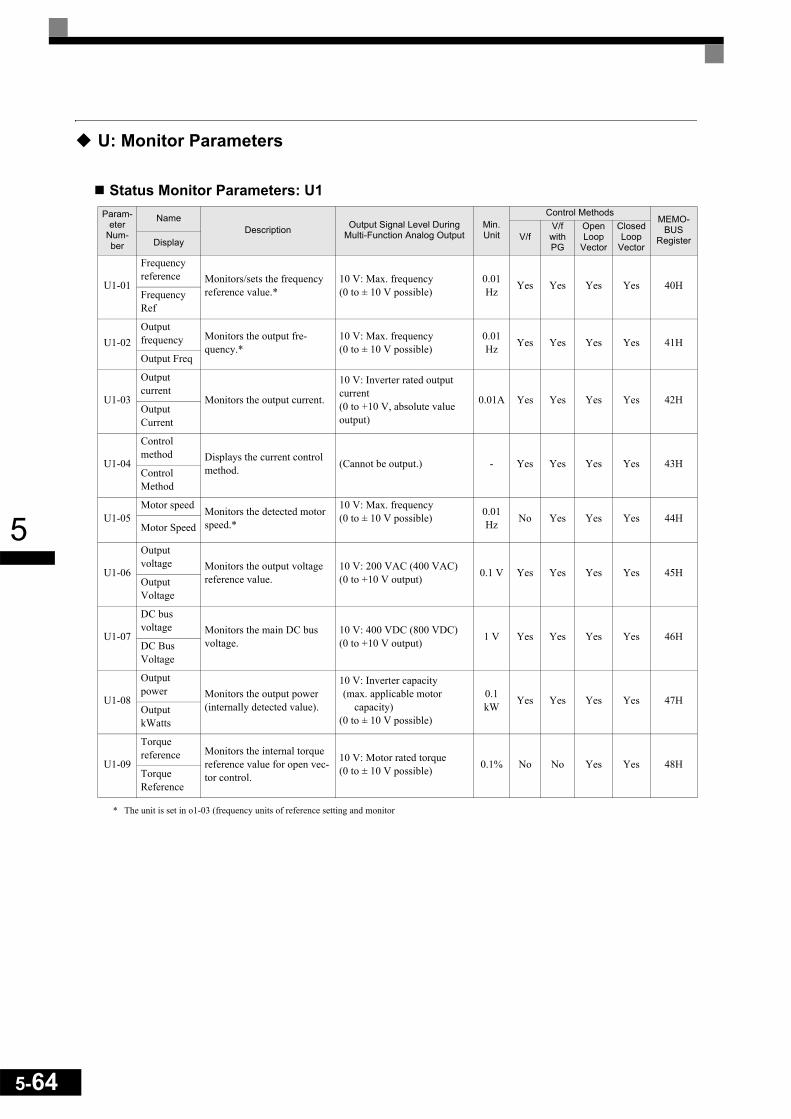
5-64
5
U: Monitor Parameters
Status Monitor Parameters: U1
* The unit is set in o1-03 (frequency units of reference setting and monitor
Param-eter
Num-ber
NameDescription Output Signal Level During
Multi-Function Analog OutputMin. Unit
Control MethodsMEMO-
BUSRegisterV/f
V/f with PG
Open Loop
Vector
Closed Loop
VectorDisplay
U1-01
Frequency reference Monitors/sets the frequency
reference value.*10 V: Max. frequency (0 to ± 10 V possible)
0.01Hz Yes Yes Yes Yes 40H
Frequency Ref
U1-02Output frequency Monitors the output fre-
quency.*10 V: Max. frequency (0 to ± 10 V possible)
0.01Hz Yes Yes Yes Yes 41H
Output Freq
U1-03
Output current
Monitors the output current.
10 V: Inverter rated output current(0 to +10 V, absolute value output)
0.01A Yes Yes Yes Yes 42HOutputCurrent
U1-04
Control method Displays the current control
method. (Cannot be output.) - Yes Yes Yes Yes 43HControl Method
U1-05Motor speed Monitors the detected motor
speed.*
10 V: Max. frequency (0 to ± 10 V possible) 0.01
Hz No Yes Yes Yes 44HMotor Speed
U1-06
Output voltage Monitors the output voltage
reference value.10 V: 200 VAC (400 VAC)(0 to +10 V output) 0.1 V Yes Yes Yes Yes 45H
Output Voltage
U1-07
DC bus voltage Monitors the main DC bus
voltage.10 V: 400 VDC (800 VDC)(0 to +10 V output) 1 V Yes Yes Yes Yes 46H
DC Bus Voltage
U1-08
Output power Monitors the output power
(internally detected value).
10 V: Inverter capacity (max. applicable motor
capacity)(0 to ± 10 V possible)
0.1 kW Yes Yes Yes Yes 47H
Output kWatts
U1-09
Torque reference Monitors the internal torque
reference value for open vec-tor control.
10 V: Motor rated torque(0 to ± 10 V possible) 0.1% No No Yes Yes 48H
Torque Reference

5
Param-eter
Num-ber
NameDescription Output Signal Level During
Multi-Function Analog OutputMin. Unit
Control MethodsMEMO-
BUSRegisterV/f
V/f with PG
Open Loop
Vector
Closed Loop
VectorDisplay
U1-10
Input termi-nal status
Shows input ON/OFF status.
(Cannot be output.) - Yes Yes Yes Yes 49HInput Term Sts
U1-11
Output ter-minal status
Shows output ON/OFF sta-tus.
(Cannot be output.) - Yes Yes Yes Yes 4AHOutput Term Sts
U1-12
Operation status
Inverter operating status.
(Cannot be output.) - Yes Yes Yes Yes 4BHInt Ctl Sts 1
U1-13
Cumulative operation time
Monitors the total operating time of the Inverter.The initial value and the operating time/power ON time selection can be set in o2-07 and o2-08.
(Cannot be output.) 1hr Yes Yes Yes Yes 4CH
Elapsed Time
U1-14
Software No. (flash memory) (Manufacturer’s ID number) (Cannot be output.) - Yes Yes Yes Yes 4DH
FLASH ID
U1-15
Terminal A1 input level
Monitors the input level of analog input A1. A value of 100% corresponds to 10V input.
10 V: 100%(0 to ± 10 V possible) 0.1% Yes Yes Yes Yes 4EH
Term A1 Level
1: FWD command(S1) is ON1: REV command(S2) is ON
1: Multi input 1(S3) is ON
1: Multi input 2(S4) is ON
1: Multi input 3(S5) is ON
1: Multi input 4(S6) is ON
1: Multi input 5(S7) is ON
1: Multi-functioncontact output 1(M1-M2) is ON
1: Multi-functioncontact output 2(M3-M4) is ON
1: Multi-functioncontact output 3(M5-M6) is ON
Not used (Always 0).1: Error output(MA/MB-MC) is ON
Run
1: Zero speed
1: Reverse1: Reset signal input
1: Speed agree
1: Inverter ready
1: Minor fault
1: Major fault
5-65

5-66
5
U1-16
Terminal A2 input level
Monitors the input level of analog input A2. A value of 100% corresponds to 10V/20mA input.
10 V/20mA: 100%(0 to ±10 V possible) 0.1% Yes Yes Yes Yes 4FH
Term A2 Level
U1-18
Motor sec-ondary cur-rent (Iq)
Monitors the calculated value of the motor secondary cur-rent.The motor rated current cor-responds to 100%.
10 V:Motor rated current)(0 to ±10 V output) 0.1% Yes Yes Yes Yes 51H
Mot SEC Current
U1-19
Motor exci-tation cur-rent (Id)
Monitors the calculated value of the motor excitation cur-rent.The motor rated current cor-responds to 100%.
10 V:Motor rated current)(0 to ±10 V output) 0.1% No No Yes Yes 52H
Mot EXC current
U1-20
Frequency reference after soft-starter
Monitors the frequency refer-ence after the soft starter.This frequency value does not include compensations, such as slip compensation.The unit is set in o1-03.
10 V: Max. frequency (0 to ± 10 V possible)
0.01Hz Yes Yes Yes Yes 53H
SFS Output
U1-21
ASR input Monitors the input to the speed control loop.The maximum frequency cor-responds to 100%.
10 V: Max. frequency (0 to ± 10 V possible)
0.01% No Yes No Yes 54H
ASR Input
U1-22
ASR output Monitors the output from the speed control loop.The maximum frequency cor-responds to 100%.
10 V:Max. frequency(0 to ± 10 V possible)
0.01% No Yes No Yes 55H
ASR output
U1-24
PID feed-back value Monitors the feedback value
when PID control is used.10 V: 100% feedback value(0 to ± 10 V possible)
0.01% Yes Yes Yes Yes 57H
PIDFeedback
U1-25
DI-16H2Input Status
Monitors the reference value from a DI-16H2 option card.The value will be displayed in binary or BCD depending on user constant F3-01.
(Cannot be output.) - Yes Yes Yes Yes 58HDI-16 Reference
U1-26
Output volt-age refer-ence (Vq)
Monitors the Inverter internal voltage reference for motor secondary current control.
10 V: 200 VAC (400 VAC)(0 to ± 10 V possible) 0.1 V No No Yes Yes 59H
Voltage Ref(Vq)
U1-27
Output volt-age refer-ence (Vd)
Monitors the Inverter internal voltage reference for motor excitation current control.
10 V: 200 VAC (400 VAC)(0 to ± 10 V possible) 0.1 V No No Yes Yes 5AH
Voltage Ref(Vd)
U1-28Software No. (CPU) (Manufacturer’s CPU soft-
ware No.) (Cannot be output.) - Yes Yes Yes Yes 5BHCPU ID
Param-eter
Num-ber
NameDescription Output Signal Level During
Multi-Function Analog OutputMin. Unit
Control MethodsMEMO-
BUSRegisterV/f
V/f with PG
Open Loop
Vector
Closed Loop
VectorDisplay

5
U1-29
kWH Lower four digits Shows the consumed energy
in kWh. U1-29 shoes the lower four digits, U1-30 shows the upper five digits.
. U1-30 U1-29
(Cannot be output.) 0.1kWh Yes Yes Yes Yes 5CH
kWh Lower 4 dig
U1-30
kWH Higher five digits
(Cannot be output.) 1MW Yes Yes Yes Yes 5DH
kWh Upper 5 dig
U1-32
ACR output of q axis Monitors the current control
output value for the motor secondary current.
10 V: 100%(0 to ± 10 V possible)
0.1% No No Yes Yes 5FH
ACR(q) Output
U1-33ACR output of d axis
Monitors the current control output value for the motor excitation current.
10 V: 100%(0 to ± 10 V possible)
0.1% No No Yes Yes 60H
ACR(d) axis
U1-34
OPE fault parameter Shows the first parameter
number when an OPE fault is detected.
(Cannot be output.) - Yes Yes Yes Yes 61HOPE Detected
U1-35
Zero servo movement pulses
Shows the number of PG pulses of the movement range when zero servo was acti-vated. The shown value is the actual pulse number times 4.
(Cannot be output.) - No No No Yes 62HZero Servo Pulse
U1-36PID input volume PID input volume 10 V: 100% PID input
(0 to ± 10 V possible)0.01% Yes Yes Yes Yes 63H
PID Input
U1-37PID output volume PID control output 10 V: 100% PID output
(0 to ± 10 V possible)0.01% Yes Yes Yes Yes 64H
PID Output
U1-38 PID setpoint PID set point 10 V: 100% PID set point 0.01% Yes Yes Yes Yes 65H
U1-39
MEMOBUScommunica-tions error code
Shows MEMOBUS errors.
(Cannot be output.) - Yes Yes Yes Yes 66H
Transmit Err
U1-40
Cooling fan operating time
Monitors the total operating time of the cooling fan. The time can be set in 02-10.
(Cannot be output.) 1hr Yes Yes Yes Yes 67H
FAN Elapsed Time
Param-eter
Num-ber
NameDescription Output Signal Level During
Multi-Function Analog OutputMin. Unit
Control MethodsMEMO-
BUSRegisterV/f
V/f with PG
Open Loop
Vector
Closed Loop
VectorDisplay
1: CRC error1: Data length error Not used
1: Parity error
1: Overrun error
1: Framing error
1: Timeout
5-67
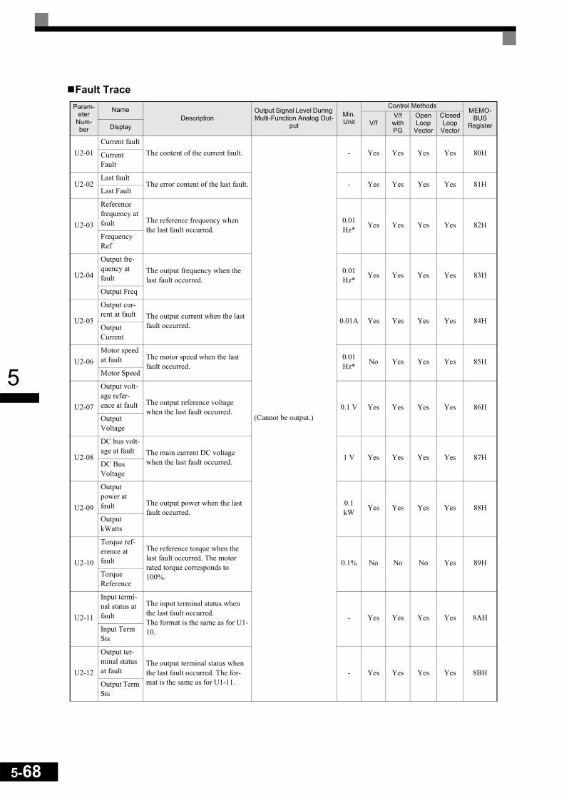
5-68
5
Fault TraceParam-
eter Num-ber
NameDescription
Output Signal Level During Multi-Function Analog Out-
put
Min. Unit
Control MethodsMEMO-
BUSRegisterV/f
V/f with PG
Open Loop
Vector
Closed Loop
VectorDisplay
U2-01Current fault
The content of the current fault.
(Cannot be output.)
- Yes Yes Yes Yes 80HCurrent Fault
U2-02Last fault
The error content of the last fault. - Yes Yes Yes Yes 81HLast Fault
U2-03
Reference frequency at fault The reference frequency when
the last fault occurred.0.01Hz* Yes Yes Yes Yes 82H
Frequency Ref
U2-04
Output fre-quency at fault
The output frequency when the last fault occurred.
0.01Hz* Yes Yes Yes Yes 83H
Output Freq
U2-05
Output cur-rent at fault The output current when the last
fault occurred. 0.01A Yes Yes Yes Yes 84HOutput Current
U2-06Motor speed at fault The motor speed when the last
fault occurred.0.01 Hz* No Yes Yes Yes 85H
Motor Speed
U2-07
Output volt-age refer-ence at fault The output reference voltage
when the last fault occurred. 0.1 V Yes Yes Yes Yes 86HOutput Voltage
U2-08
DC bus volt-age at fault The main current DC voltage
when the last fault occurred. 1 V Yes Yes Yes Yes 87HDC Bus Voltage
U2-09
Output power at fault The output power when the last
fault occurred.0.1 kW Yes Yes Yes Yes 88H
Output kWatts
U2-10
Torque ref-erence at fault
The reference torque when the last fault occurred. The motor rated torque corresponds to 100%.
0.1% No No No Yes 89HTorque Reference
U2-11
Input termi-nal status at fault
The input terminal status when the last fault occurred.The format is the same as for U1-10.
- Yes Yes Yes Yes 8AHInput Term Sts
U2-12
Output ter-minal status at fault
The output terminal status when the last fault occurred. The for-mat is the same as for U1-11.
- Yes Yes Yes Yes 8BHOutput Term Sts

5
* The unit is set in o1-03 (frequency units of reference setting and monitor
Fault History: U3
U2-13
Operation status at fault
The operating status when the last fault occurred. The format is the same as for U1-12.
(Cannot be output.)
- Yes Yes Yes Yes 8CHInverter Sta-tus
U2-14
Cumulative operation time at fault The operating time when the last
fault occurred.1hr Yes Yes Yes Yes 8DH
Elapsed Time
Param-eter
Number
NameDescription Output Signal Level During
Multi-Function Analog OutputMin. Unit
MEMO-BUS
RegisterDisplay
U3-01Last fault
The error content of 1st last fault.
(Cannot be output.)
- 90HLast Fault
U3-02Second last fault
The error content of 2nd last fault. - 91HFault Message 2
U3-03Third last fault
The error content of 3rd last fault. - 92HFault Message 3
U3-04Fourth last fault
The error content of 4th last fault. - 93HFault Message 4
U3-05Cumulative opera-tion time at fault The total operating time when the 1st previous
fault occurred.1hr 94H
Elapsed Time 1
U3-06Accumulated time of second fault The total operating time when the 2nd previous
fault occurred.1hr 95H
Elapsed Time 2
U3-07Accumulated time of third fault The total operating time when the 3rd previous
fault occurred.1hr 96H
Elapsed Time 3
U3-08Accumulated time of fourth/oldest fault The total operating time when the 4th previous
fault occurred. 1hr 97H
Elapsed Time 4
U3-09 –
U3-14
Fifth last to tenth last fault
The error content of the 5th to 10th last fault –
804805H806H807H808H809H
Fault Message 5 to 10
U3-15 –
U3-20
Accumulated time of fifth to tenth fault
Total generating time when 5th ... 10th previous fault occurred 1hr
806H80FH810H811H812H813H
Elapsed Time 5 to 10
IMPORTANT
The following errors are not recorded in the Fault Trace and Fault History: CPF00, 01, 02, 03, UV1, and UV2.
Param-eter
Num-ber
NameDescription
Output Signal Level During Multi-Function Analog Out-
put
Min. Unit
Control MethodsMEMO-
BUSRegisterV/f
V/f with PG
Open Loop
Vector
Closed Loop
VectorDisplay
5-69

5-70
5
Factory Settings that Change with the Control Method (A1-02)
* 1. The settings are 0.05 (Closed Loop Vector) / 2.00 (Open Loop vector) for inverters of 55kW or larger.* 2. Settings vary as shown in the following tables depending on the Inverter capacity and E1-03.* 3. The settings shown are for 200 V class Inverters. The values will double for 400 V class Inverters.* 4. The given setting range is valid if Heavy Duty is selected (C6-01=0, default setting). If Normal Duty 1 or 2 is selected (C6-01=1 or 2) the setting range
will be 0.0 to 400.0 Hz.
Parameter
Num-ber
Name Setting Range Unit
Factory Setting
V/f ControlA1-02=0
V/F with PG
A1-02=1
Open Loop Vector
A1-02=2
Closed Loop Vec-
tor A1-02=3
b3-01 Speed search selection 0 to 3 - 2 3 2 -
b3-02 Speed search operating current 0 to 200 1% 120 - 100 -
b8-02 Energy saving gain 0.0 to 10.0 - - - 0.7 1.0
b8-03 Energy saving filter time constant 0.0 to 10.0 - - - 0.50*1
0.01*1
C3-01 Slip compensation gain 0.0 to 2.5 - 0.0 - 1.0 1.0
C3-02 Slip compensation primary delay time con-stant 0 to 10000 1 ms 2000 - 200 -
C4-02 Torque compensation primary delay time constant 0 to 10000 1 ms 200 200 20 -
C5-01 ASR proportional gain 1 0.00 to 300.00 - - 0.20 - 20.00
C5-02 ASR integral time 1 0.000 to 10.000 1 ms - 0.200 - 0.500
C5-03 ASR proportional gain 2 0.00 to 300.00 - - 0.02 - 20.00
C5-04 ASR integral time 2 0.000 to 10.000 1 ms - 0.050 - 0.500
C5-06 ASR delay time 0.000 to 0.500 0.001 - - - 000.4
d5-02 Torque reference delay time 0 to 1000 1 ms - - - 0
E1-07E3-05 Mid. output frequency (VB)*2 0.0 to 150.0
*4 0.1 V 2.5 2.5 3.0 -
E1-08E3-06 Mid. output frequency voltage (VB)*2 0.0 to 255.0
(0.0 to 510.0) 0.1 V 15.0*2*3
15.0*2*3 13.2 -
E1-09E3-07 Min. output frequency (FMIN) 0.0 to 150.0
*4 0.1 Hz 1.2*2
1.5*2 0.5 0.0
E1-10E3-08 Min. output frequency voltage (VMIN)*2 0.0 to 255.0
(0.0 to 510.0) 0.1 V 9.0*2*3
9.0*2*3 2.4 -
F1-09 Over speed detection time 0.0 to 2.0 1 - 1.0 - 0.0

5
200 V and 400 V Class Inverters of 0.4 to 1.5 kW*
* The settings shown are for 200 V class Inverters. The values will double for 400 V class Inverters.
200 V and 400 V Class Inverters of 2.2 to 45 kW*
* The settings shown are for 200 V class Inverters. The values will double for 400 V class Inverters.
200 V Class Inverters of 55 to 110 kW and 400 V Class Inverters of 55 to 300 kW*
* The settings shown are for 200 V class Inverters. The values will double for 400 V class Inverters.
Param-eter
NumberUnit Factory Setting Open
Loop Vector Control
Closed Loop
Vector ControlE1-03 - 0 1 2 3 4 5 6 7 8 9 A B C D E F
E1-04 Hz 50.0 60.0 60.0 72.0 50.0 50.0 60.0 60.0 50.0 50.0 60.0 60.0 90.0 120.0 180.0 60.0 50.0 60.0
E1-05* V 200.0 200.0 200.0 200.0 200.0 200.0 200.0 200.0 200.0 200.0 200.0 200.0 200.0 200.0 200.0 200.0 200.0 200.0
E1-06 Hz 50.0 60.0 50.0 60.0 50.0 50.0 60.0 60.0 50.0 50.0 60.0 60.0 60.0 60.0 60.0 60.0 50.0 60.0
E1-07* Hz 2.5 3.0 3.0 3.0 25.0 25.0 30.0 30.0 2.5 2.5 3.0 3.0 3.0 3.0 3.0 3.0 3.0 0.0
E1-08* V 15.0 15.0 15.0 15.0 35.0 50.0 35.0 50.0 19.0 24.0 19.0 24.0 15.0 15.0 15.0 15.0 13.2 0.0
E1-09 Hz 1.3 1.5 1.5 1.5 1.3 1.3 1.5 1.5 1.3 1.3 1.5 1.5 1.5 1.5 1.5 1.5 0.5 0.0
E1-10* V 9.0 9.0 9.0 9.0 8.0 9.0 8.0 9.0 11.0 13.0 11.0 15.0 9.0 9.0 9.0 9.0 2.4 0.0
Param-eter
NumberUnit Factory Setting Open
Loop Vector Control
Closed Loop
Vector ControlE1-03 - 0 1 2 3 4 5 6 7 8 9 A B C D E F
E1-04 Hz 50.0 60.0 60.0 72.0 50.0 50.0 60.0 60.0 50.0 50.0 60.0 60.0 90.0 120.0 180.0 60.0 60.0 60.0
E1-05* V 200.0 200.0 200.0 200.0 200.0 200.0 200.0 200.0 200.0 200.0 200.0 200.0 200.0 200.0 200.0 200.0 200.0 200.0
E1-06 Hz 50.0 60.0 50.0 60.0 50.0 50.0 60.0 60.0 50.0 50.0 60.0 60.0 60.0 60.0 60.0 60.0 60.0 60.0
E1-07* Hz 2.5 3.0 3.0 3.0 25.0 25.0 30.0 30.0 2.5 2.5 3.0 3.0 3.0 3.0 3.0 3.0 3.0 0.0
E1-08* V 14.0 14.0 14.0 14.0 35.0 50.0 35.0 50.0 18.0 23.0 18.0 23.0 14.0 14.0 14.0 14.0 11.0 0.0
E1-09 Hz 1.3 1.5 1.5 1.5 1.3 1.3 1.5 1.5 1.3 1.3 1.5 1.5 1.5 1.5 1.5 1.5 0.5 0.0
E1-10* V 7.0 7.0 7.0 7.0 6.0 7.0 6.0 7.0 9.0 11.0 9.0 13.0 7.0 7.0 7.0 7.0 2.0 0.0
Param-eter
NumberUnit Factory Setting Open
Loop Vector Control
Closed Loop
Vector ControlE1-
03 - 0 1 2 3 4 5 6 7 8 9 A B C D E F
E1-04 Hz 50.0 60.0 60.0 72.0 50.0 50.0 60.0 60.0 50.0 50.0 60.0 60.0 90.0 120.0 180.0 60.0 60.0 60.0
E1-05* V 200.0 200.0 200.0 200.0 200.0 200.0 200.0 200.0 200.0 200.0 200.0 200.0 200.0 200.0 200.0 200.0 200.0 200.0
E1-06 Hz 50.0 60.0 50.0 60.0 50.0 50.0 60.0 60.0 50.0 50.0 60.0 60.0 60.0 60.0 60.0 60.0 60.0 60.0
E1-07* Hz 2.5 3.0 3.0 3.0 25.0 25.0 30.0 30.0 2.5 2.5 3.0 3.0 3.0 3.0 3.0 3.0 3.0 0.0
E1-08* V 12.0 12.0 12.0 12.0 35.0 50.0 35.0 50.0 15.0 20.0 15.0 20.0 12.0 12.0 12.0 12.0 11.0 0.0
E1-09 Hz 1.3 1.5 1.5 1.5 1.3 1.3 1.5 1.5 1.3 1.3 1.5 1.5 1.5 1.5 1.5 1.5 0.5 0.0
E1-10* V 6.0 6.0 6.0 6.0 5.0 6.0 5.0 6.0 7.0 9.0 7.0 11.0 6.0 6.0 6.0 6.0 2.0 0.0
5-71
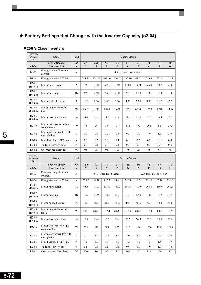
5-72
5
Factory Settings that Change with the Inverter Capacity (o2-04)
200 V Class InvertersParame-ter Num-
berName Unit Factory Setting
- Inverter Capacity kW 0.4 0.75 1.5 2.2 3.7 5.5 7.5 11 15o2-04 kVA selection - 0 1 2 3 4 5 6 7 8
b8-03 Energy-saving filter time constant s 0.50 (Open Loop vector)
b8-04 Energy-saving coefficient - 288.20 223.70 169.40 156.80 122.90 94.75 72.69 70.44 63.13
E2-01(E4-01) Motor rated current A 1.90 3.30 6.20 8.50 14.00 19.60 26.60 39.7 53.0
E2-02(E4-02) Motor rated slip Hz 2.90 2.50 2.60 2.90 2.73 1.50 1.30 1.70 1.60
E2-03(E4-03) Motor no-load current A 1.20 1.80 2.80 3.00 4.50 5.10 8.00 11.2 15.2
E2-05(E4-05)
Motor line-to-line resis-tance W 9.842 5.156 1.997 1.601 0.771 0.399 0.288 0.230 0.138
E2-06(E4-06) Motor leak inductance % 18.2 13.8 18.5 18.4 19.6 18.2 15.5 19.5 17.2
E2-10 Motor iron loss for torque compensation W 14 26 53 77 112 172 262 245 272
L2-02 Momentary power loss rid through time s 0.1 0.1 0.2 0.3 0.5 1.0 1.0 1.0 2.0
L2-03 Min. baseblock (BB) time s 0.1 0.2 0.3 0.4 0.5 0.6 0.7 0.8 0.9
L2-04 Voltage recovery time s 0.3 0.3 0.3 0.3 0.3 0.3 0.3 0.3 0.3
L8-02 Overheat pre-alarm level °C 95 95 95 100 95 95 95 95 90
Parame-ter Num-
berName Unit Factory Setting
- Inverter Capacity kW 18.5 22 30 37 45 55 75 90 110o2-04 kVA selection - 9 A B C D E F 10 11
b8-03 Energy-saving filter time constant s 0.50 (Open Loop vector) 2.00 (Open Loop vector)
b8-04 Energy-saving coefficient - 57.87 51.79 46.27 38.16 35.78 31.35 23.10 23.10 23.10
E2-01(E4-01) Motor rated current A 65.8 77.2 105.0 131.0 160.0 190.0 260.0 260.0 260.0
E2-02(E4-02) Motor rated slip Hz 1.67 1.70 1.80 1.33 1.60 1.43 1.39 1.39 1.39
E2-03(E4-03) Motor no-load current A 15.7 18.5 21.9 38.2 44.0 45.6 72.0 72.0 72.0
E2-05(E4-05)
Motor line-to-line resis-tance W 0.101 0.079 0.064 0.039 0.030 0.022 0.023 0.023 0.023
E2-06(E4-06) Motor leak inductance % 20.1 19.5 20.8 18.8 20.2 20.5 20.0 20.0 20.0
E2-10 Motor iron loss for torque compensation W 505 538 699 823 852 960 1200 1200 1200
L2-02 Momentary power loss ride through time s 2.0 2.0 2.0 2.0 2.0 2.0 2.0 2.0 2.0
L2-03 Min. baseblock (BB) time s 1.0 1.0 1.1 1.1 1.2 1.2 1.3 1.5 1.7
L2-04 Voltage recovery time s 0.6 0.6 0.6 0.6 0.6 1.0 1.0 1.0 1.0
L8-02 Overheat pre-alarm level °C 100 90 90 95 100 105 110 100 95

5
400 V Class InvertersParame-ter Num-
berName Unit Factory Setting
- Inverter Capacity kW 0.4 0.75 1.5 2.2 3.7 4.0 5.5 7.5 11 15o2-04 kVA selection - 20 21 22 23 24 25 26 27 28 29
b8-03 Energy-saving filter time constant s 0.50 (Open Loop vector)
b8-04 Energy-saving coefficient - 576.40 447.40 338.80 313.60 245.80 236.44 189.50 145.38 140.88 126.26E2-01
(E4-01) Motor rated current A 1.00 1.60 3.10 4.20 7.00 7.00 9.80 13.30 19.9 26.5
E2-02(E4-02) Motor rated slip Hz 2.90 2.60 2.50 3.00 2.70 2.70 1.50 1.30 1.70 1.60
E2-03(E4-03) Motor no-load current A 0.60 0.80 1.40 1.50 2.30 2.30 2.60 4.00 5.6 7.6
E2-05(E4-05)
Motor line-to-line resis-tance W 38.198 22.459 10.100 6.495 3.333 3.333 1.595 1.152 0.922 0.550
E2-06(E4-06) Motor leak inductance % 18.2 14.3 18.3 18.7 19.3 19.3 18.2 15.5 19.6 17.2
E2-10 Motor iron loss for torque compensation W 14 26 53 77 130 130 193 263 385 440
L2-02 Momentary power loss ride through time s 0.1 0.1 0.2 0.3 0.5 0.5 0.8 0.8 1.0 2.0
L2-03 Min. baseblock (BB) time s 0.1 0.2 0.3 0.4 0.5 0.6 0.6 0.7 0.8 0.9L2-04 Voltage recovery time s 0.3 0.3 0.3 0.3 0.3 0.3 0.3 0.3 0.3 0.3L8-02 Overheat pre-alarm level °C 95 95 95 90 95 95 95 90 95 95
Parame-ter Num-
berName Unit Factory Setting
- Inverter Capacity kW 18.5 22 30 37 45 55 75 90 110 132o2-04 kVA selection - 2A 2B 2C 2D 2E 2F 30 31 32 33
b8-03 Energy-saving filter time constant s 0.50 (Open Loop vector) 2.00 (Open Loop vector)
b8-04 Energy-saving coefficient - 115.74 103.58 92.54 76.32 71.56 67.20 46.20 41.22 36.23 33.18E2-01
(E4-01) Motor rated current A 32.9 38.6 52.3 65.6 79.7 95.0 130.0 156.0 190.0 223.0
E2-02(E4-02) Motor rated slip Hz 1.67 1.70 1.80 1.33 1.60 1.46 1.39 1.40 1.40 1.38
E2-03(E4-03) Motor no-load current A 7.8 9.2 10.9 19.1 22.0 24.0 36.0 40.0 49.0 58.0
E2-05(E4-05)
Motor line-to-line resis-tance W 0.403 0.316 0.269 0.155 0.122 0.088 0.092 0.056 0.046 0.035
E2-06(E4-06) Motor leak inductance % 20.1 23.5 20.7 18.8 19.9 20.0 20.0 20.0 20.0 20.0
E2-10 Motor iron loss for torque compensation W 508 586 750 925 1125 1260 1600 1760 2150 2350
L2-02 Momentary power loss ride through time s 2.0 2.0 2.0 2.0 2.0 2.0 2.0 2.0 2.0 2.0
L2-03 Min. baseblock (BB) time s 1.0 1.0 1.1 1.1 1.2 1.2 1.3 1.5 1.7 1.7L2-04 Voltage recovery time s 0.6 0.6 0.6 0.6 0.6 1.0 1.0 1.0 1.0 1.0L8-02 Overheat pre-alarm level °C 98 78 85 85 90 90 98 108 100 110
5-73
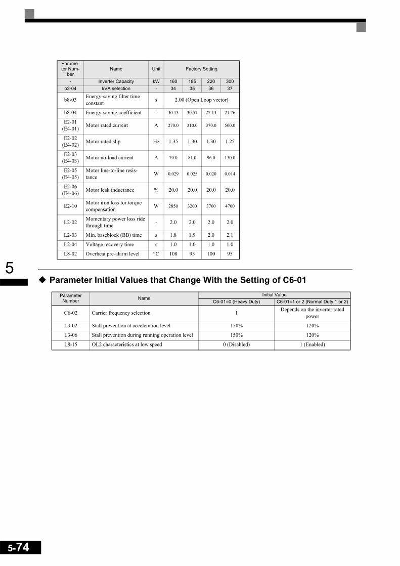
5-74
5
Parameter Initial Values that Change With the Setting of C6-01Parame-ter Num-
berName Unit Factory Setting
- Inverter Capacity kW 160 185 220 300o2-04 kVA selection - 34 35 36 37
b8-03 Energy-saving filter time constant s 2.00 (Open Loop vector)
b8-04 Energy-saving coefficient - 30.13 30.57 27.13 21.76
E2-01(E4-01) Motor rated current A 270.0 310.0 370.0 500.0
E2-02(E4-02) Motor rated slip Hz 1.35 1.30 1.30 1.25
E2-03(E4-03) Motor no-load current A 70.0 81.0 96.0 130.0
E2-05(E4-05)
Motor line-to-line resis-tance W 0.029 0.025 0.020 0.014
E2-06(E4-06) Motor leak inductance % 20.0 20.0 20.0 20.0
E2-10 Motor iron loss for torque compensation W 2850 3200 3700 4700
L2-02 Momentary power loss ride through time - 2.0 2.0 2.0 2.0
L2-03 Min. baseblock (BB) time s 1.8 1.9 2.0 2.1
L2-04 Voltage recovery time s 1.0 1.0 1.0 1.0
L8-02 Overheat pre-alarm level °C 108 95 100 95
Parameter Number Name
Initial ValueC6-01=0 (Heavy Duty) C6-01=1 or 2 (Normal Duty 1 or 2)
C6-02 Carrier frequency selection 1 Depends on the inverter rated power
L3-02 Stall prevention at acceleration level 150% 120%
L3-06 Stall prevention during running operation level 150% 120%
L8-15 OL2 characteristics at low speed 0 (Disabled) 1 (Enabled)

5
Parameter Setting Ranges that Change With the Setting of C6-01
Parameter Number Name
Setting Range
C6-01=0 (Heavy Duty) C6-01=1 or 2 (Normal Duty 1 or 2)
C6-02 Carrier frequency selection 0,6,F 0 to 6, F (depends on the inverter rated power)
b5-15 PID sleep function operation level
Upper Limit = 150.0 Hz Upper Limit = 400.0 Hz
b6-01 Dwell frequency at start
b6-03 Dwell frequency at stop
C1-11 Accel./Decel. time switching frequency
C5-07 ASR gain switching frequency
d3-01 Jump frequency 1
d3-02 Jump frequency 2
d3-03 Jump frequency 3
d6-02 Field weakening limit
E1-04 Maximum output frequency
E1-06 Base frequency
E1-07 Middle output frequency
E1-09 Minimum output frequency
E1-11 Middle output frequency 2
E3-02 Motor 2 maximum output frequency
E3-04 Motor 2 base frequency
E3-05 Motor 2 middle output frequency
E3-07 Motor 2 minimum output frequency
L4-01 Frequency detection level
L4-03 Frequency detection bandwidth -150.0 to +150.0 Hz -400.0 to 400.0 Hz
5-75

5-76
5

6 Parameter Settings by
Function Application and Overload Selections .....................................6-2 Frequency Reference ............................................................6-7 Run Command Input Methods .............................................6-12 Stopping Methods ................................................................6-14 Acceleration and Deceleration Characteristics ....................6-19 Adjusting Frequency References.........................................6-26 Speed Limit (Frequency Reference Limits)..........................6-30 Frequency Detection............................................................6-31 Improving the Operation Performance.................................6-33 Machine Protection ..............................................................6-43 Automatic Restart ................................................................6-52 Inverter Protection................................................................6-59 Input Terminal Functions .....................................................6-64 Output Terminal Functions...................................................6-74 Monitor Parameters .............................................................6-77 Individual Functions .............................................................6-80 Digital Operator Functions .................................................6-130 Option Cards......................................................................6-138
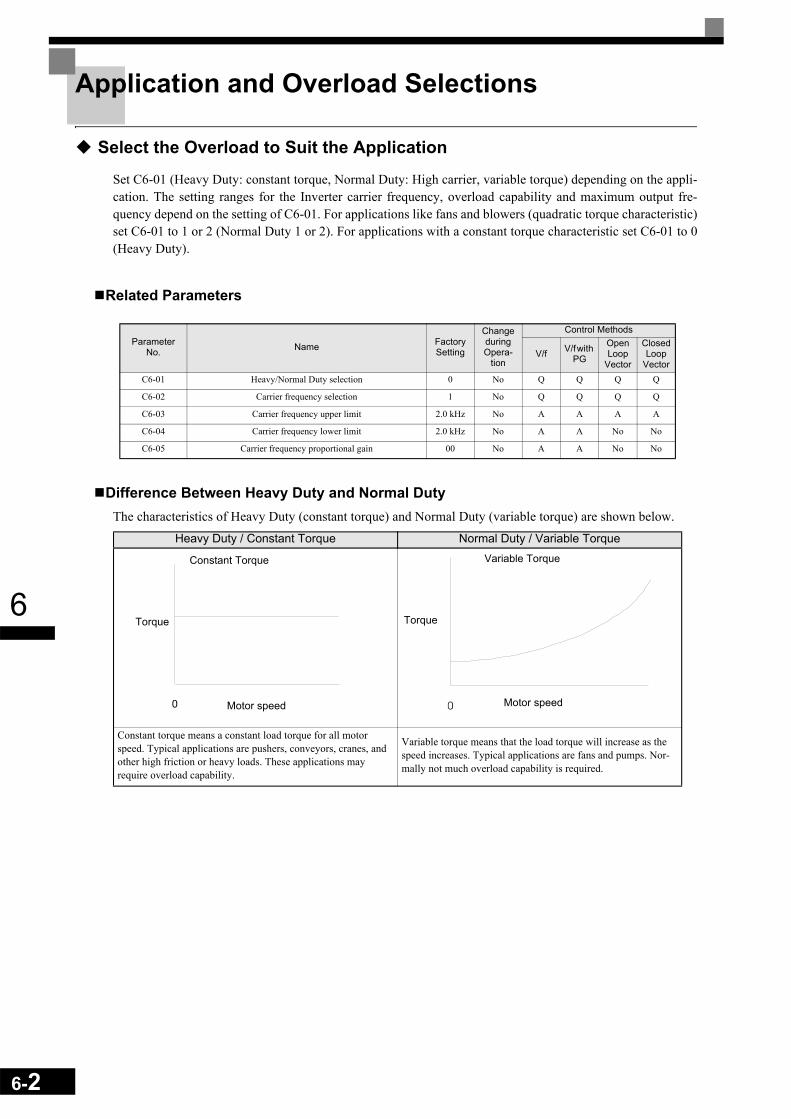
6-2
6
Application and Overload Selections
Select the Overload to Suit the Application
Set C6-01 (Heavy Duty: constant torque, Normal Duty: High carrier, variable torque) depending on the appli-cation. The setting ranges for the Inverter carrier frequency, overload capability and maximum output fre-quency depend on the setting of C6-01. For applications like fans and blowers (quadratic torque characteristic)set C6-01 to 1 or 2 (Normal Duty 1 or 2). For applications with a constant torque characteristic set C6-01 to 0(Heavy Duty).
Related Parameters
Difference Between Heavy Duty and Normal DutyThe characteristics of Heavy Duty (constant torque) and Normal Duty (variable torque) are shown below.
Parameter No. Name Factory
Setting
Change during Opera-
tion
Control Methods
V/f V/f with PG
Open Loop
Vector
Closed Loop
VectorC6-01 Heavy/Normal Duty selection 0 No Q Q Q Q
C6-02 Carrier frequency selection 1 No Q Q Q Q
C6-03 Carrier frequency upper limit 2.0 kHz No A A A A
C6-04 Carrier frequency lower limit 2.0 kHz No A A No No
C6-05 Carrier frequency proportional gain 00 No A A No No
Heavy Duty / Constant Torque Normal Duty / Variable Torque
Constant torque means a constant load torque for all motor speed. Typical applications are pushers, conveyors, cranes, and other high friction or heavy loads. These applications may require overload capability.
Variable torque means that the load torque will increase as the speed increases. Typical applications are fans and pumps. Nor-mally not much overload capability is required.
Constant Torque
Torque
Motor speed
Variable Torque
Torque
Motor speed

6
Setting Precautions
C6-01 (Heavy/Normal Duty Selection)The inverter supplies Heavy/Normal Duty modes Heavy Duty, Normal Duty 1 and Normal Duty 2. The set-ting ranges and factory settings of some parameters change with the setting of C6-01. See page 5-74, Parame-ter Initial Values that Change With the Setting of C6-01 and page 5-75, Parameter Setting Ranges thatChange With the Setting of C6-01.
The table below shows the main differences of the three modes.
* 1. The rated current depends on on the Heavy/Normal Duty selection. (See page -2, Specifications by Model for details)* 2. If the carrier frequency in Heavy Duty mode is set to a higher value than 2.5kHz, a current derating must be considered.* 3. The factory setting and the maximum carrier frequency depend on the inverter capacity. (See page -2, Specifications by Model for details)
Carrier Frequency SelectionWhen selecting the carrier frequency, observe the following precautions:
• Adjust the carrier frequency according to the cases shown below.• If the wiring distance between Inverter and motor is long: Set the carrier frequency low. (Use the fol-
lowing values as guidelines.
• If speed and torque vary at low speeds: Lower the carrier frequency.• If Inverter noise is affecting peripheral devices: Lower the carrier frequency.• If leakage current from the Inverter is large: Lower the carrier frequency.• If metallic noise from the motor is large: Increase the carrier frequency.
C6-01 Set Value 0 (Heavy Duty) 1 (Normal Duty 1) 2 (Normal Duty 2)
Inverter Current Overload Capa-bility
150% of the Heavy Duty rated current for 1 min. *1
120% of the Normal Duty 1 rated cur-rent for 1 min. *1
120% of the Normal Duty 2 rated cur-rent for 1 min.*1
C6-02 (Carrier Frequency Selec-tion)
0: Low carrier frequency, low noise1: 2 kHz6: 15kHz *2
0: Low carrier low noise1: Carrier 2 kHz2: Carrier 5 kHz*3
3: Carrier 8.0 kHz*3
4: Carrier 10.0 kHz*3
5: Carrier 12.5 kHz*3
6: Carrier 15 kHz*3
F: User-set*3
E1-04 and E3-02 (Max. Output Frequency) 150 Hz 400 Hz
L3-02 (Stall Prevention Level During Acceleration) 150% 120%
L3-06 (Stall Prevention Level During Operation) 150% 120%
L8-15 (OL2 Characteristics at low Speed) 0 (Disabled) 1 (Enabled)
Wiring Length 50 m or less 100 m or less Over 100 mC6-02 (carrier frequency) setting 0 to 6 (15 kHz) 0 to 4 (10 kHz) 0 to 2 (5 kHz)
6-3
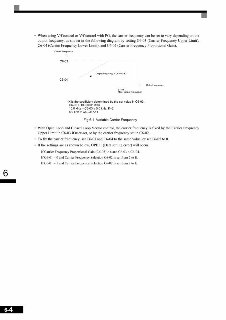
6-4
6
• When using V/f control or V/f control with PG, the carrier frequency can be set to vary depending on theoutput frequency, as shown in the following diagram by setting C6-03 (Carrier Frequency Upper Limit),C6-04 (Carrier Frequency Lower Limit), and C6-05 (Carrier Frequency Proportional Gain).
Fig 6.1 Variable Carrier Frequency
• With Open Loop and Closed Loop Vector control, the carrier frequency is fixed by the Carrier FrequencyUpper Limit in C6-03 if user-set, or by the carrier frequency set in C6-02.
• To fix the carrier frequency, set C6-03 and C6-04 to the same value, or set C6-05 to 0.• If the settings are as shown below, OPE11 (Data setting error) will occur.
If Carrier Frequency Proportional Gain (C6-05) > 6 and C6-03 < C6-04.
If C6-01 = 0 and Carrier Frequency Selection C6-02 is set from 2 to E.
If C6-01 = 1 and Carrier Frequency Selection C6-02 is set from 7 to E.
Carrier Frequency
Output frequency
E1-04Max. Output Frequency
Output frequency x C6-05 x K*
C6-03
C6-04
*K is the coefficient determined by the set value in C6-03. C6-03 ≥ 10.0 kHz: K=3 10.0 kHz > C6-03 ≥ 5.0 kHz: K=2 5.0 kHz > C6-03: K=1

6
Carrier Frequency and Inverter Overload CapabilityThe inverter overload capability depends among other things on the carrier frequency setting. If the carrier fre-quency setting is higher than the factory setting, the overload current capability must be reduced.
Heavy Duty (C6-01=0)The default carrier frequency for the Heavy Duty mode is 2 kHz. The overload capability is 150% of theHeavy Duty rated current for 1 minute.If the carrier frequency is increased, a derating for the continuous output current like shown on Fig 6.2 mustbe considered. The overload capability (OL2 Level) does not change. It will be 150% of the derated currentfor 1 min.
Fig 6.2 Current Derating in Heavy Duty Mode
50
60
70
80
90
100
110
2 4 6 8 10 12 14
Carrier Frequency (kHz)
Out
put C
urre
nt (%
)
200V/400V 22kW and less200V 30kW / 400V 30 to 55kW200V 37 to 90kW / 400V 75 to 160kW400V 185kW200V 110kW / 400V 220 and 300kW
6-5

6-6
6
Normal Duty 1 (C6-01=1)The default carrier frequency for the Normal Duty 1 mode depends on the inverter capacity. The overloadcapability is 120% of the Normal Duty 1 rated current for 1 minute.If the carrier frequency is set to a higher value than the factory setting, the overload capability is reduced likeshown in Fig 6.3.
Fig 6.3 Overload Capability in Normal Duty 1 Mode
Normal Duty 2 (C6-01=2)In the Normal Duty 2 mode the maximum carrier frequency is decreased compared to the Normal Duty 1mode but the short term overload capability is increased. Refer to Fig 6.4 for the overload capability of bothmodes.
Fig 6.4 Normal Duty 1 and 2 Inverter Overload Detection Curve
120%
96%
5kHz 10kHz 15kHz0
Out
put C
urre
nt fo
r 1 m
in.
Carrier Freq.8kHz
200V Class 37 to 90kW400V Class 75 to 110kW
400V Class 132kW
200V Class 0.4 to 22kW400V Class 0.4 to 22kW
90%
200V Class 30kW400V Class 30 to 55kW400V Class 160kW
0.1
1
10
100
100 110 120 130 140 150 160 170 180 190 200
Overload Level [%]
Inve
rter
Ove
rload
Det
ectio
n Ti
me
[min
]
Normal Duty 1 Normal Duty 2

6
Frequency Reference
Selecting the Frequency Reference Source
Set parameter b1-01 to select the frequency reference source.
Related Parameters
Input the Frequency Reference from the Digital OperatorWhen b1-01 is set to 0, you can input the frequency reference from the Digital Operator.
For details on setting the frequency reference, refer to page 3-1, Digital Operator and Modes.
Fig 6.5 Frequency Setting Display
Inputting the Frequency Reference Using Voltage (Analog Setting)When b1-01 is set to 1, you can input the frequency reference from control circuit terminal A1 (voltage input),or control circuit terminal A2 (voltage or current input).
Inputting Master Speed Frequency Reference OnlyIf inputting the master speed frequency reference only, input the voltage reference to control circuit terminalA1.
Fig 6.6 Master Speed Frequency Reference Input
Parameter No. Name Factory
Setting
Change during Opera-
tion
Control Methods
V/f V/f with PG
Open Loop
Vector
Closed Loop
Vectorb1-01 Frequency reference source selection 1 No Q Q Q Q
H3-09 Analog input 2 function selection 0 No A A A A
H3-13 Terminal A1/A2 main reference input switching 0 No A A A A
H6-01 Pulse train input function selection 0 No A A A A
H6-02 Pulse train input scaling 1440 Hz No A A A A
-DRIVE- Rdy
Frequency RefU1-01= 0 0 0.0 0Hz
"0.00Hz"
Inverter
A1(Master frequency reference)
+V(Power supply: 15 V, 20 mA)
A2(Auxiliary frequency reference)
AC (Analog common)
2 kΩ
2 kΩ
6-7
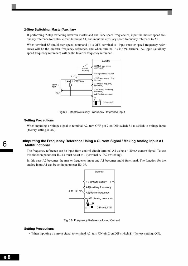
6-8
6
2-Step Switching: Master/AuxiliaryIf performing 2-step switching between master and auxiliary speed frequencies, input the master speed fre-quency reference to control circuit terminal A1, and input the auxiliary speed frequency reference to A2.
When terminal S3 (multi-step speed command 1) is OFF, terminal A1 input (master speed frequency refer-ence) will be the Inverter frequency reference, and when terminal S3 is ON, terminal A2 input (auxiliaryspeed frequency reference) will be the Inverter frequency reference.
Fig 6.7 Master/Auxiliary Frequency Reference Input
Setting PrecautionsWhen inputting a voltage signal to terminal A2, turn OFF pin 2 on DIP switch S1 to switch to voltage input(factory setting is ON).
Inputting the Frequency Reference Using a Current Signal / Making Analog Input A1 Multifunctional
The frequency reference can be input from control circuit terminal A2 using a 4-20mA current signal. To usethis function parameter H3-13 must be set to 1 (terminal A1/A2 switching).
In this case A2 becomes the master frequency input and A1 becomes multi-functional. The function for theanalog input A1 can be set in parameter H3-09.
Fig 6.8 Frequency Reference Using Current
Setting Precautions• When inputting a current signal to terminal A2, turn ON pin 2 on DIP switch S1 (factory setting: ON).
0 to 10 V input
Inverter
+V (Power supply: 15 V, 20 mA)
A1(Master frequency reference)
DIP switch S1
SN Digital input neutral
S3 Multi-step speed command 1Master/
Auxiliary
A2(Auxiliary frequency reference)AC (Analog common)
2 kΩ
2 kΩ
2 kΩ0 to 10 V input
Inverter
+V (Power supply: 15 V,
A1(Auxiliary frequency
A2(Master frequency
AC (Analog common)
4 to 20 mA
DIP switch S1

6
Setting Frequency Reference Using Pulse Train SignalsWhen b1-01 is set to 4, the pulse train input signal at terminal RP input is used as the frequency reference.
Set H6-01 (Pulse Train Input Function Selection) to 0 (frequency reference), and then set the reference pulsefrequency that is equal to 100% of the reference value to H6-02 (Pulse Train Input Scaling).
Fig 6.9 Frequency Reference Using Pulse Train Input
Pulse Input SpecificationsLow level voltage 0.0 to 0.8 V
High level voltage 3.5 to 13.2 V
Pulse duty factor 30 to 70%
Pulse frequency 0 to 32 kHz
Inverter
32 kHz max.3.5 to 13.2 V
Pulse input(Pulse train input terminal)
(Analog common)
6-9

6-10
6
Using Multi-Step Speed Operation
The inverter supports a multi step speed operation with a maximum of 17 speed steps, using 16 multi-step fre-quency references, and one jog frequency reference.
The following example of a multi-function input terminal function shows a 9-step operation using multi-stepreferences 1 to 3 and jog frequency selection functions.
Related ParametersTo switch frequency references, set multi-step references 1 to 3 and the jog reference selection in the multi-function digital inputs.
Multi-function Digital Inputs (H1-01 to H1-05)
Combining Multi-Step Speed References and Digital InputsYou can change the selected frequency reference by combining the ON/OFF status of S4 to S7 (digital inputterminals). The following table shows the possible combinations.
* Terminal S7's jog frequency selection is given priority over multi-step speed commands.
Terminal Parameter Number Set Value Details
S4 H1-02 5 Multi-step speed command 3
S5 H1-03 3 (default) Multi-step speed command 1 (Also used for master speed/auxiliary speed switching when multi-function analog input H3-09 is set to 2 (auxiliary frequency reference).)
S6 H1-04 4 (default) Multi-step speed command 2
S7 H1-05 6 (default) Jog frequency selection (given priority over multi-step speed command)
SpeedMulti-step
Speed Com-mand 1
Multi-step Speed Com-
mand 2
Multi-step Speed Com-
mand 3
Jog Fre-quency Selec-
tionSelected Frequency
1 OFF OFF OFF OFF Frequency reference 1 d1-01, master speed frequency
2 ON OFF OFF OFF Frequency reference 2 d1-02, auxiliary frequency
3 OFF ON OFF OFF Frequency reference 3 d1-03
4 ON ON OFF OFF Frequency reference 4 d1-04
5 OFF OFF ON OFF Frequency reference 5 d1-05
6 ON OFF ON OFF Frequency reference 6 d1-06
7 OFF ON ON OFF Frequency reference 7 d1-07
8 ON ON ON OFF Frequency reference 8 d1-08
17 - - - ON* Jog frequency d1-17
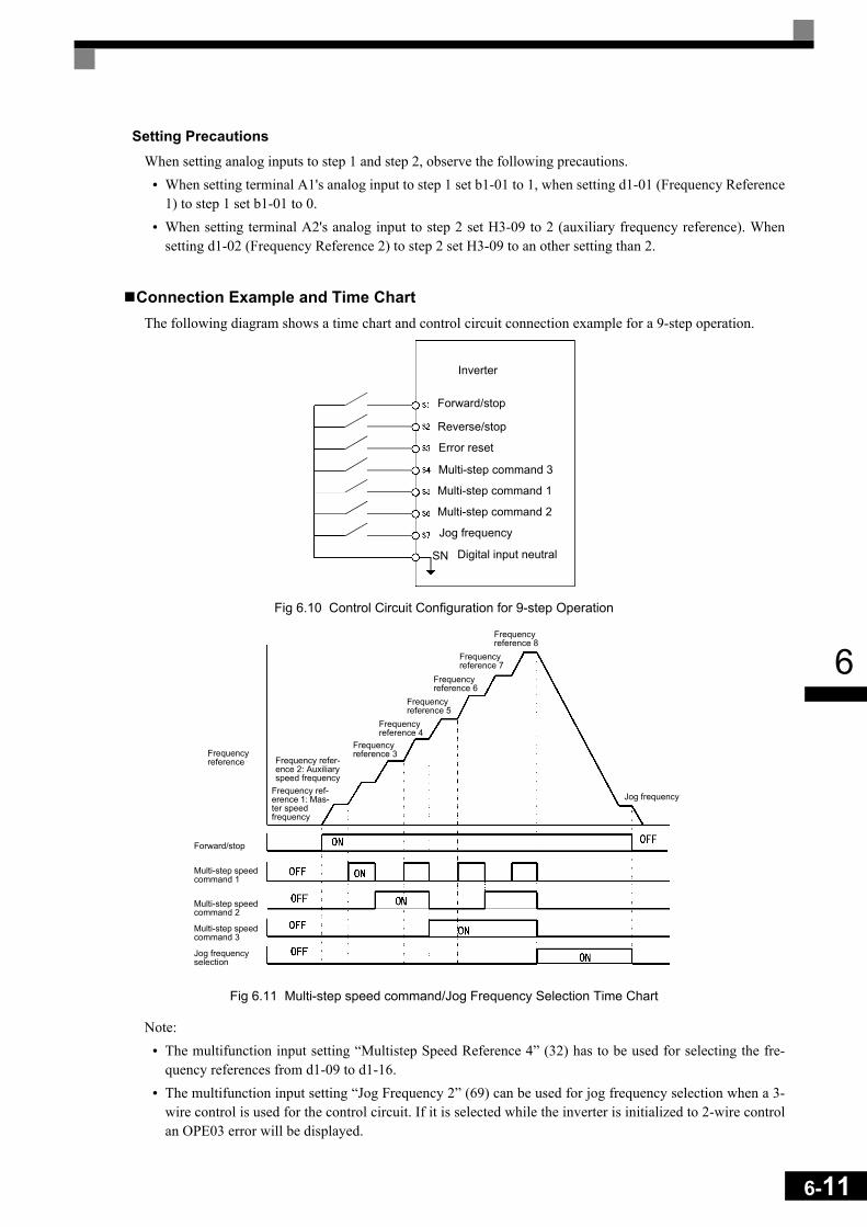
6
Setting PrecautionsWhen setting analog inputs to step 1 and step 2, observe the following precautions.
• When setting terminal A1's analog input to step 1 set b1-01 to 1, when setting d1-01 (Frequency Reference1) to step 1 set b1-01 to 0.
• When setting terminal A2's analog input to step 2 set H3-09 to 2 (auxiliary frequency reference). Whensetting d1-02 (Frequency Reference 2) to step 2 set H3-09 to an other setting than 2.
Connection Example and Time ChartThe following diagram shows a time chart and control circuit connection example for a 9-step operation.
Fig 6.10 Control Circuit Configuration for 9-step Operation
Fig 6.11 Multi-step speed command/Jog Frequency Selection Time Chart
Note:• The multifunction input setting “Multistep Speed Reference 4” (32) has to be used for selecting the fre-
quency references from d1-09 to d1-16.• The multifunction input setting “Jog Frequency 2” (69) can be used for jog frequency selection when a 3-
wire control is used for the control circuit. If it is selected while the inverter is initialized to 2-wire controlan OPE03 error will be displayed.
Inverter
Forward/stop
Reverse/stop
Error reset
Multi-step command 3
Multi-step command 1
Multi-step command 2
Jog frequency
Digital input neutralSN
Forward/stop
Multi-step speed command 1
Multi-step speed command 2
Multi-step speed command 3
Jog frequency selection
Frequency refer-ence 2: Auxiliary speed frequency
Frequency reference 3
Frequency reference 4
Frequency reference 5
Frequency reference 6
Jog frequency
Frequency reference 8
Frequency reference 7
Frequency reference
Frequency ref-erence 1: Mas-ter speed frequency
6-11

6-12
6
Run Command Input Methods
Selecting the Run Command Source
Set parameter b1-02 to select the source for the run command.
Related Parameters
Performing Operations Using the Digital OperatorWhen b1-02 is set to 0, you can perform Inverter operations using the Digital Operator keys (RUN, STOP, andFWD/REV). For details on the Digital Operator, refer to page 3-1, Digital Operator and Modes.
Performing Operations Using Control Circuit TerminalsWhen b1-02 is set to 1, you can perform Inverter operations using the control circuit terminals.
Performing Operations Using a 2-wire ControlThe factory setting is set to a 2-wire control. When the control circuit terminal S1 is set to ON, forward opera-tion will be performed, and when S1 is turned OFF, the Inverter will stop. In the same way, when the controlcircuit terminal S2 is set to ON, reverse operation will be performed, and when S2 is turned OFF, the Inverterwill stop.
Fig 6.12 2-Wire Control Wiring Example with Positive Logic
Parameter No. Name Factory
Setting
Change during Opera-
tion
Control Methods
V/f V/f with PG
Open Loop
Vector
Closed Loop
Vectorb1-02 RUN command source selection 1 No Q Q Q Q
InverterForward/Stop
Reverse/Stop
SN Digital input neutral

6
Performing Operations Using 3-Wire ControlIf one of the parameter H1-01 to H1-05 (digital input terminals S3 to S7) is set to 0, the terminals S1 and S2are used for a 3-wire control, and the multi-function input terminal that has been set to 0 works as a forward/reverse selection command terminal.
When the Inverter is initialized for 3-wire control with A1-03, multi-function input 3 becomes the input termi-nal for the forward/reverse run command.
Fig 6.13 3-Wire Control Wiring Example
Fig 6.14 Three-wire Control Timing Chart
INFO
Use a control circuit that turns ON terminal S1 for 50 ms or longer for the run command. This will make the run command self-holding in the Inverter.
Stop switch (NC contact)
Operation switch (NO contact)
Run command (operates when ON)
Stop command (stopped when ON)
Forward/reverse command (multi-function input)
Digital input neutralSN
50 ms min.Run command
Forward/reverse command
Motor speed
Can be either ON or OFFOFF (stopped)
OFF (forward) ON (reverse)
Stop Forward Reverse Stop Forward
Stop command
6-13
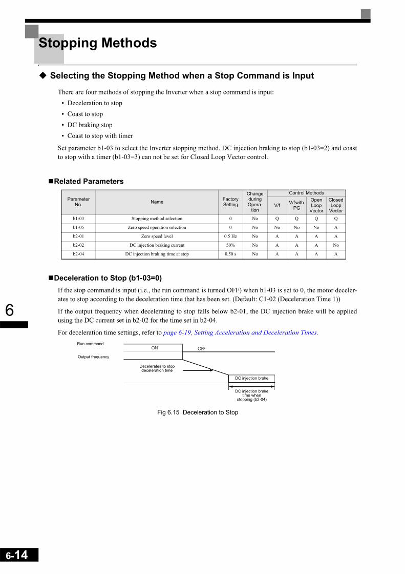
6-14
6
Stopping Methods
Selecting the Stopping Method when a Stop Command is Input
There are four methods of stopping the Inverter when a stop command is input:• Deceleration to stop• Coast to stop• DC braking stop• Coast to stop with timer
Set parameter b1-03 to select the Inverter stopping method. DC injection braking to stop (b1-03=2) and coastto stop with a timer (b1-03=3) can not be set for Closed Loop Vector control.
Related Parameters
Deceleration to Stop (b1-03=0)If the stop command is input (i.e., the run command is turned OFF) when b1-03 is set to 0, the motor deceler-ates to stop according to the deceleration time that has been set. (Default: C1-02 (Deceleration Time 1))
If the output frequency when decelerating to stop falls below b2-01, the DC injection brake will be appliedusing the DC current set in b2-02 for the time set in b2-04.
For deceleration time settings, refer to page 6-19, Setting Acceleration and Deceleration Times.
Fig 6.15 Deceleration to Stop
Parameter No. Name Factory
Setting
Change during Opera-
tion
Control Methods
V/f V/f with PG
Open Loop
Vector
Closed Loop
Vectorb1-03 Stopping method selection 0 No Q Q Q Q
b1-05 Zero speed operation selection 0 No No No No A
b2-01 Zero speed level 0.5 Hz No A A A A
b2-02 DC injection braking current 50% No A A A No
b2-04 DC injection braking time at stop 0.50 s No A A A A
Run command
Output frequency
DC injection brake
Decelerates to stop deceleration time
DC injection brake time when
stopping (b2-04)

6
When Closed Loop Vector control is selected, the stopping behavior depends on the setting of b1-05.
Fig 6.16 Deceleration to Stop in Closed Loop Vector Control
Coast to Stop (b1-03=1)When b1-03 is set to 1 and the Run command is turned off, the inverter output will be interrupted immediatelyand the motor will coast to stop. The time until the motor stands depends on the inertia and load situation.
Fig 6.17 Coast to Stop
INFO
After the stop command is input, Run commands are ignored until the Minimum Baseblock Time (L2-03) has elapsed.
RUN OFF ON
Analogfrequencyreference
0
E1-09
b1-05=0Run at frequencyreference
Initial excitation
Baseblock
Zero speedcontrol
Baseblock
The Run command turnsOFF and zero speedcontrol starts when themotor speed feedbackdrops below b2-01.
b2-03 b2-04
b1-05=1Coast to stop
Baseblock b2-03 b2-04 Baseblock
Initial excitation Zero speedcontrol
The frequency reference dropsto less than E1-09 and zerospeed control starts when themotor speed feedback dropsbelow b2-01.
b1-05=2Run at minimumfrequency E1-09
Baseblock b2-03
Initialexcitation
The Run command turns OFFand zero speed control startswhen the motor speed feedbackdrops below b2-01.
The Run command turns OFF andzero speed control starts whenmotor speed feedback drops belowb2-01.
Zero speedcontrol
Zero speedcontrol
b2-04 Baseblock
Baseblock b2-03 b2-04 Baseblock
Initial excitationb1-05=3Zero SpeedOperation
fref
fout
fout
fout
fout
ON OFFRun command
Output frequency
Inverter output frequency interrupted
6-15
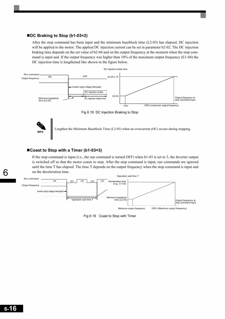
6-16
6
DC Braking to Stop (b1-03=2)After the stop command has been input and the minimum baseblock time (L2-03) has elapsed, DC injectionwill be applied to the motor. The applied DC injection current can be set in parameter b2-02. The DC injectionbraking time depends on the set value of b2-04 and on the output frequency at the moment when the stop com-mand is input and. If the output frequency was higher than 10% of the maximum output frequency (E1-04) theDC injection time is lengthened like shown in the figure below.
Fig 6.18 DC Injection Braking to Stop
Coast to Stop with a Timer (b1-03=3)If the stop command is input (i.e., the run command is turned OFF) when b1-03 is set to 3, the Inverter outputis switched off so that the motor coasts to stop. After the stop command is input, run commands are ignoreduntil the time T has elapsed. The time T depends on the output frequency when the stop command is input andon the deceleration time.
Fig 6.19 Coast to Stop with Timer
INFOLengthen the Minimum Baseblock Time (L2-03) when an overcurrent (OC) occurs during stopping.
Output frequency at stop command input
100% (maximum output frequency10%
b2-04
b2-04 x 10
DC injection brake time
Run command
Output frequency
DC injection brake
ON OFF
Inverter output voltage interrupted
Minimum baseblock time (L2-03)
DC injection brake time
Run command
Output frequency
Operation wait time T
Minimum output frequency 100% (Maximum output frequency)
Deceleration time(e.g., C1-02)
Minimum baseblocktime (L2-03) Output frequency at
stop command input
Inverter output voltage interrupted
Operation wait time T

6
Using the DC Injection Brake
The DC injection brake can be used to stop a coasting motor before restarting it or to hold it at the decelerationend when the inertia is large. Set parameter b2-03 to apply DC injection to the motor, before it starts to accel-erate. Set parameter b2-04 to apply a DC injection brake to the motor at stopping.
Setting b2-03/04 to 0 to disables the DC injection brake at start/stop.
Set the DC injection brake current using b2-02.
Related Parameters
Multi-function Digital Inputs (H1-01 to H1-05)
Inputting the DC Injection Brake Command from Control Circuit TerminalsIf you set a digital input terminal (H1- ) to 60 (DC injection brake command), the DC brake can be appliedby enabling or disabling this input. The time chart for the DC injection brake is shown below.
Fig 6.20 DC Injection Brake Time Chart
Parameter No. Name Factory
Setting
Change during Opera-
tion
Control Methods
V/f V/f with PG
Open Loop
Vector
Closed Loop
Vectorb2-01 Zero speed level (DC injection braking starting frequency) 0.5 Hz No A A A A
b2-02 DC injection braking current 50% No A A A No
b2-03 DC injection braking time at start 0.00 s No A A A A
b2-04 DC injection braking time at stop 0.50 s No A A A A
Set Value Function
Control Methods
V/fV/f
with PG
Open Loop
Vector
Closed Loop
Vector60 DC injection brake command Yes Yes Yes Yes
If you input the DC injection brake command from an external terminal, and if a run commandor jog command is input, the DC injection brake will be disabled, and operation will resume.
DC injection brake command
FRUN
Output frequency
DC injection brakeDC injection brake E1-09 b2-01
6-17

6-18
6
Changing the DC Injection Brake Current Using an Analog InputIf you set H3-09 (Analog Input Terminal A2 Function Selection) to 6 (DC injection brake current), you canchange the DC injection brake current level using the analog input.
At 10 V input (voltage) or 20 mA input (current), 100% of the Inverter rated current will be applied.
Fig 6.21 DC Injection Brake Current Using an Analog Input
Using an Emergency Stop
Set a digital input terminal (H1- ) to 15 or 17 (emergency stop) to decelerate to stop using the emergencystop deceleration time set in C1-09. If inputting the emergency stop with an NO contact, set the multi-functioninput terminal (H1- ) to 15, and if inputting the emergency stop with an NC contact, set the multi-functioninput terminal (H1- ) to 17.
After the emergency stop command has been input, operation cannot be restarted until the Inverter hasstopped. To cancel the emergency stop, turn OFF the run command and emergency stop command.
Related parameters
Multi-function Digital Inputs (H1-01 to H1-05)
Parameter No. Name Factory
Setting
Change during Opera-
tion
Control Methods
V/f V/f with PG
Open Loop
Vector
Closed Loop
VectorC1-09 Emergency stop time 10.0 s No A A A A
Set Value Function
Control Methods
V/fV/f with PG
Open Loop
Vector
Closed Loop
Vector15 Emergency Stop, NO contact Yes Yes Yes Yes
17 Emergency Stop, NC contact Yes Yes Yes Yes
DC injection brake current level
Inverter rated current

6
Acceleration and Deceleration Characteristics
Setting Acceleration and Deceleration Times
The acceleration time indicates the time to increase the output frequency from 0% to 100% of the maximumoutput frequency (E1-04). The deceleration time indicates the time to decrease the output frequency from100% to 0% of (E1-04). The accel./decel. times 1 are used with the factory setting, the accel./decel. times 2 to4 can be selected using a multifunction digital input.
Related Parameters
Multi-function Digital Inputs (H1-01 to H1-05)
Setting Acceleration and Deceleration Time UnitsSet the acceleration/deceleration time units using C1-10. The factory setting is 1.
Parameter No. Name Factory
Setting
Change during Opera-
tion
Control Methods
V/f V/f with PG
Open Loop
Vector
Closed Loop
VectorC1-01 Acceleration time 1
10.0 s
Yes Q Q Q Q
C1-02 Deceleration time 1 Yes Q Q Q Q
C1-03 Acceleration time 2 Yes A A A A
C1-04 Deceleration time 2 Yes A A A A
C1-05 Acceleration time 3 No A A A A
C1-06 Deceleration time 3 No A A A A
C1-07 Acceleration time 4 No A A A A
C1-08 Deceleration time 4 No A A A A
C1-10 Acceleration/deceleration time setting unit 1 No A A A A
C1-11 Acceleration/deceleration time switching frequency 0.0 Hz No A A A A
C2-01 S-curve characteristic time at acceleration start 0.20 s No A A A A
C2-02 S-curve characteristic time at acceleration end 0.20 s No A A A A
C2-03 S-curve characteristic time at deceleration start 0.20 s No A A A A
C2-04 S-curve characteristic time at deceleration end 0.00 s No A A A A
Set Value Function
Control Methods
V/fV/f with PG
Open Loop
Vector
Closed Loop
Vector7 Acceleration/Deceleration time 1 Yes Yes Yes Yes
1A Acceleration/Deceleration time 2 Yes Yes Yes Yes
Set value Details
0 The acceleration/deceleration time setting range is 0.00 to 600.00 in units of 0.01 s.
1 The acceleration/deceleration time setting range is 0.00 to 6000.0 in units of 0.1 s.
6-19
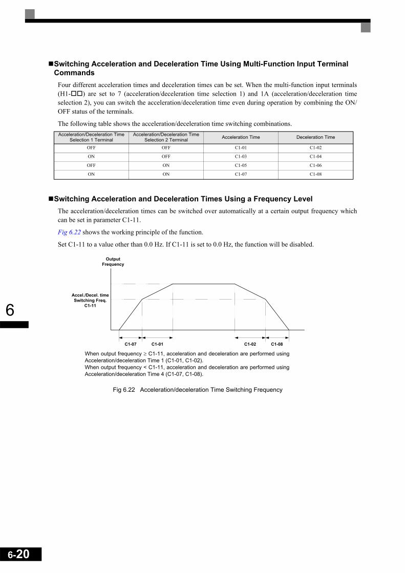
6-20
6
Switching Acceleration and Deceleration Time Using Multi-Function Input Terminal Commands
Four different acceleration times and deceleration times can be set. When the multi-function input terminals(H1- ) are set to 7 (acceleration/deceleration time selection 1) and 1A (acceleration/deceleration timeselection 2), you can switch the acceleration/deceleration time even during operation by combining the ON/OFF status of the terminals.
The following table shows the acceleration/deceleration time switching combinations.
Switching Acceleration and Deceleration Times Using a Frequency LevelThe acceleration/deceleration times can be switched over automatically at a certain output frequency whichcan be set in parameter C1-11.
Fig 6.22 shows the working principle of the function.
Set C1-11 to a value other than 0.0 Hz. If C1-11 is set to 0.0 Hz, the function will be disabled.
Fig 6.22 Acceleration/deceleration Time Switching Frequency
Acceleration/Deceleration Time Selection 1 Terminal
Acceleration/Deceleration Time Selection 2 Terminal Acceleration Time Deceleration Time
OFF OFF C1-01 C1-02
ON OFF C1-03 C1-04
OFF ON C1-05 C1-06
ON ON C1-07 C1-08
OutputFrequency
Accel./Decel. timeSwitching Freq.
C1-11
C1-07 C1-01 C1-02 C1-08
When output frequency ≥ C1-11, acceleration and deceleration are performed usingAcceleration/deceleration Time 1 (C1-01, C1-02).When output frequency < C1-11, acceleration and deceleration are performed usingAcceleration/deceleration Time 4 (C1-07, C1-08).

6
Adjusting Acceleration and Deceleration Time Using an Analog InputIf you set H3-09 (Analog Input Terminal A2 Function Selection) to 5 (acceleration/deceleration time gain),you can adjust the acceleration/deceleration time using terminal A2's input voltage.
The resulting acceleration time is as follows:
Acceleration time = C1-01 set value x acceleration/deceleration time gain
Fig 6.23 Acceleration/Deceleration Time Gain Using an Analog Input
Entering S-curve Characteristics in the Acceleration and Deceleration TimeBy performing acceleration and deceleration using an S-curve pattern, you can reduce shock when starting andstopping the machine.
Four different S-curve characteristic times can be set: At acceleration start, at deceleration start, at accelera-tion end and at deceleration end.
Setting ExampleThe S-curve characteristic when switching operation (forward/reverse) is shown in the following diagram.
Fig 6.24 S-curve Characteristic during Operation Switching
INFO
When S-curve is set, calculate acceleration/deceleration time as follows:
Acceleration/deceleration time gain
(Acceleration/deceleration gain from 1 to 10 V)= 10 V/Input voltage (V) x 10 (%)
Accel.Time C2-01 C2-02+2
------------------------------------ C1-01/03/05/07+=
Decel. Time C2-03 C2-04+2
------------------------------------ C1-02/04/06/08+=
Forward
Reverse
Output frequency
6-21

6-22
6
Accelerating and Decelerating Heavy Loads (Dwell Function)
The dwell function holds the output frequency temporarily when starting or stopping heavy loads. When usingthe dwell function, deceleration to stop must be set as stopping method (b1-03 = 0).
Related Parameters
Applying an Output Frequency DwellAn output frequency dwell can be applied to prevent a stalling of the motor at start if the static friction and theinertia are large or to prevent a coasting of the motor at stop. The frequency level at which the dwell functionstarts can be set separately for the start and the stop in the parameters b6-01 and b6-03. The times can be set inthe parameters b6-02 and b6-04 (refer to Fig 6.25)
Fig 6.25 Output Frequency Dwell Settings
Preventing the Motor from Stalling During Acceleration (Stall Prevention During Acceleration Function)
The Stall Prevention During Acceleration function prevents the motor from stalling if a heavy load is appliedto the motor, or sudden rapid acceleration is performed.
If L3-01 is set to 1 (enabled) and the Inverter output current reaches 85 % of the set value in L3-02, the accel-eration rate will begin to slow down. When L3-02 is exceeded, the acceleration will stop.
If L3-01 is set to 2 (optimum adjustment), the motor accelerates so that the current is held at the level set inL3-03. With this setting, the acceleration time setting is ignored.
Related Parameters
* Shows the initial value when C6-01 is set to 0 (default). If C6-01 is set to 1 or 2, the initial value is 120%.
Parameter No. Name Factory
Setting
Change during Opera-
tion
Control Methods
V/f V/f with PG
Open Loop
Vector
Closed Loop
Vectorb6-01 Dwell frequency at start 0.0 Hz No A A A A
b6-02 Dwell time at start 0.0 s No A A A A
b6-03 Dwell frequency at stop 0.0 Hz No A A A A
b6-04 Dwell time at stop 0.0 s No A A A A
Parameter No. Name Factory
Setting
Change during Opera-
tion
Control Methods
V/f V/f with PG
Open Loop
Vector
Closed Loop
VectorL3-01 Stall prevention selection during acceleration 1 No A A A No
L3-02 Stall prevention level during acceleration 150%* No A A A No
L3-03 Stall prevention limit during acceleration 50% No A A A No
Run command
Output frequency
Time
ON
b6-03
OFF
b6-01
b6-04b6-02

6
Time ChartThe following figure shows the frequency characteristics when L3-01 is set to 1.
Fig 6.26 Time Chart for Stall Prevention During Acceleration
Setting Precautions• If the motor capacity is small compared to the Inverter capacity or if the inverter is operated using the fac-
tory settings and the motor stalls, lower the set value of L3-02.• If using the motor in the constant power range, L3-02 will be automatically lowered to prevent stalling.
L3-03 is the limit value to prevent the stall prevention level in the constant power range from beingreduced more than necessary (see Fig 6.27).
• Set the parameters as a percentage taking the inverter rated current to be 100%.
Fig 6.27 Stall Prevention Level and Limit During Acceleration
Output current
Stall level duringacceleration
Time
Time
Output frequency
* 1. The acceleration rate is lowered.* 2. The acceleration is stopped to reduce the output current.
*1. *2.
L3-0285% of L3-02
Stall prevention level duringacceleration
L3-02 (Stall Prevention Level during Acceleration)
L3-03 (Stall Prevention Limit during Acceleration)
Output frequencyE1-06Base Frequency (FA)
6-23
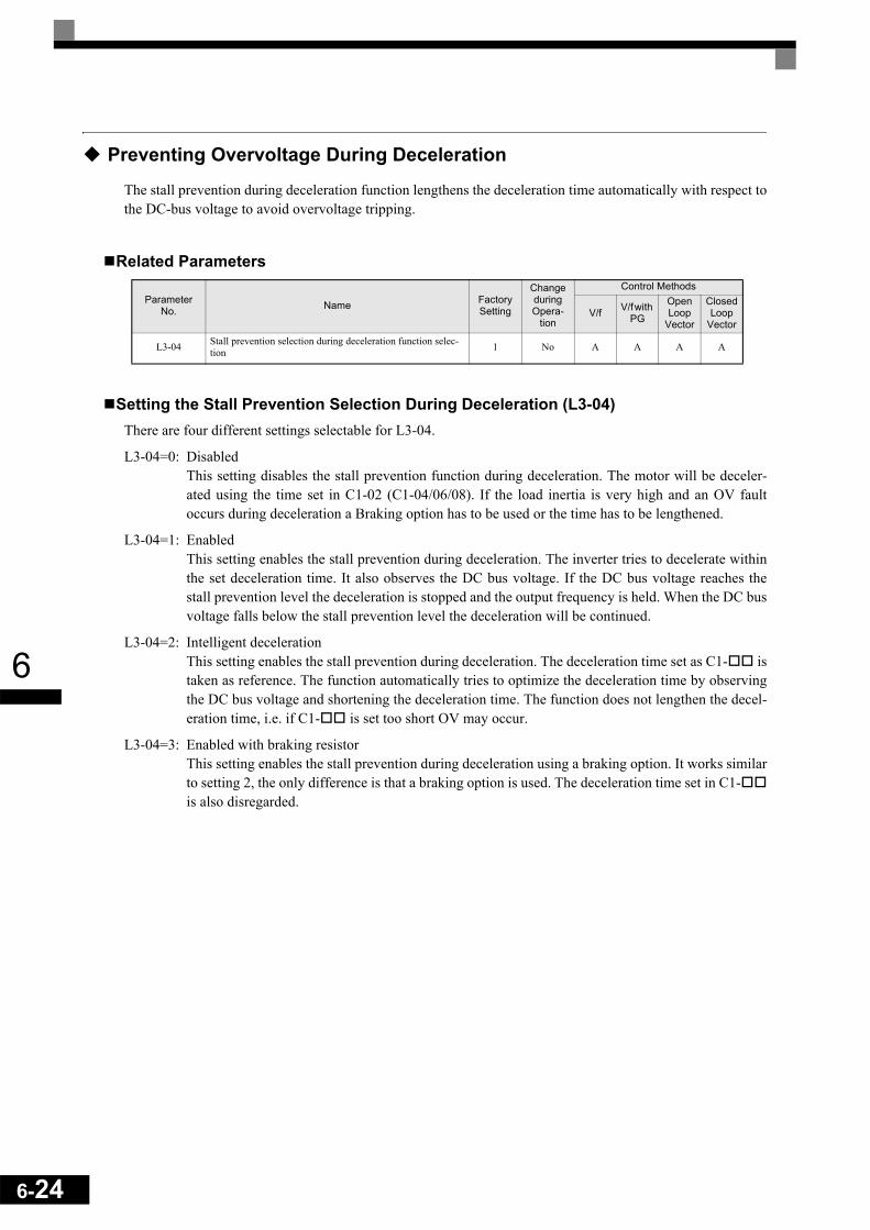
6-24
6
Preventing Overvoltage During Deceleration
The stall prevention during deceleration function lengthens the deceleration time automatically with respect tothe DC-bus voltage to avoid overvoltage tripping.
Related Parameters
Setting the Stall Prevention Selection During Deceleration (L3-04)There are four different settings selectable for L3-04.
L3-04=0: DisabledThis setting disables the stall prevention function during deceleration. The motor will be deceler-ated using the time set in C1-02 (C1-04/06/08). If the load inertia is very high and an OV faultoccurs during deceleration a Braking option has to be used or the time has to be lengthened.
L3-04=1: EnabledThis setting enables the stall prevention during deceleration. The inverter tries to decelerate withinthe set deceleration time. It also observes the DC bus voltage. If the DC bus voltage reaches thestall prevention level the deceleration is stopped and the output frequency is held. When the DC busvoltage falls below the stall prevention level the deceleration will be continued.
L3-04=2: Intelligent decelerationThis setting enables the stall prevention during deceleration. The deceleration time set as C1- istaken as reference. The function automatically tries to optimize the deceleration time by observingthe DC bus voltage and shortening the deceleration time. The function does not lengthen the decel-eration time, i.e. if C1- is set too short OV may occur.
L3-04=3: Enabled with braking resistorThis setting enables the stall prevention during deceleration using a braking option. It works similarto setting 2, the only difference is that a braking option is used. The deceleration time set in C1-is also disregarded.
Parameter No. Name Factory
Setting
Change during Opera-
tion
Control Methods
V/f V/f with PG
Open Loop
Vector
Closed Loop
Vector
L3-04 Stall prevention selection during deceleration function selec-tion 1 No A A A A

6
Setting ExampleAn example of stall prevention during deceleration when L3-04 is set to 1 is shown below.
Fig 6.28 Stall Prevention During Deceleration Operation
Setting Precautions• The stall prevention level during deceleration differs depending on the inverter rated voltage and input
voltage. Refer to the following table for details.
• When using the braking option (braking resistor, braking resistor units, and braking units), be sure to setparameter L3-04 to 0 or 3.
• When a braking option is used and the deceleration time shall be optimized (shorter than setting of C1-02/04/06/08), L3-04 has to be set to 3.
Inverter Rated/Input Voltage Stall Prevention Level during Deceleration (V)
200 V class 380
400 V classE1-01 ≥ 400 V 760
E1-01 < 400 V 660
Deceleration time controlled toprevent overvoltage
Deceleration time (set value)
Time
Output frequency
6-25

6-26
6
Adjusting Frequency References
Adjusting Analog Frequency References
The analog reference values can be adjusted using the gain and bias functions for the analog inputs.
Related Parameters
Adjusting Analog Frequency Reference Using ParametersThe frequency reference can be input from the control circuit terminals using analog voltage or current signals(analog input A2 only).
The input signal levels can be selected using• H3-01 for the analog input A1• H3-08 for the analog input A2
Adjustments to the signals can be made using:• H3-02 (Gain) and H3-03 (Bias) if analog input A1 is selected to be the frequency reference input• H3-10 (Gain) and H3-11 (Bias) if analog input A2 is selected to be the frequency reference input
Refer to Fig 6.29 for adjusting the signal using the gain and bias functions.
Fig 6.29 Terminals A1 and A2 Inputs
Parameter No. Name Factory
Setting
Change during Opera-
tion
Control Methods
V/f V/f with PG
Open Loop
Vector
Closed Loop
VectorH3-01 Multi-function analog input terminal A1 signal level selection 0 No A A A A
H3-02 Frequency reference terminal A1 input gain 100.0% Yes A A A A
H3-03 Frequency reference terminal A1 input bias 0.0% Yes A A A A
H3-08 Multi-function analog A2 signal level selection 2 No A A A A
H3-09 Multi-function analog A2 function selection 0 No A A A A
H3-10 Multi-function analog A2 input gain 100.0% Yes A A A A
H3-11 Multi-function analog A2 input bias 0.0% Yes A A A A
H3-12 Analog input filter time constant 0.03 s No A A A A
H3-13 Terminal A1/A2 switching 0 No A A A A
Frequency reference
Terminal A1 input
Terminal A1input voltage
Frequency reference
Terminal A2 input
Terminal A2 inputvoltage (current)
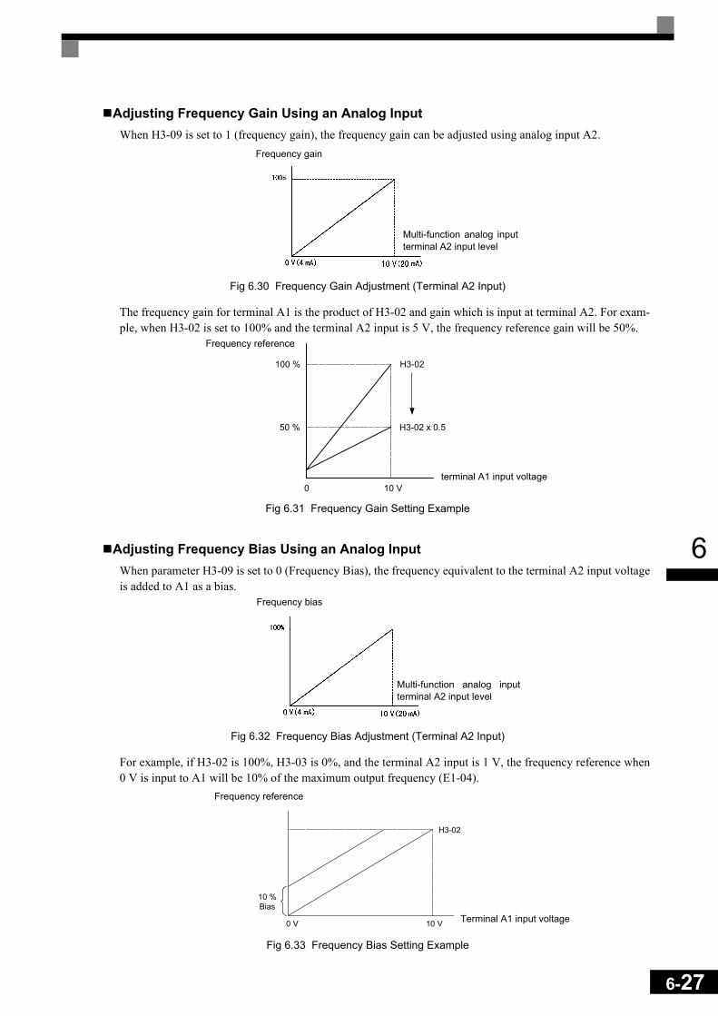
6
Adjusting Frequency Gain Using an Analog InputWhen H3-09 is set to 1 (frequency gain), the frequency gain can be adjusted using analog input A2.
Fig 6.30 Frequency Gain Adjustment (Terminal A2 Input)
The frequency gain for terminal A1 is the product of H3-02 and gain which is input at terminal A2. For exam-ple, when H3-02 is set to 100% and the terminal A2 input is 5 V, the frequency reference gain will be 50%.
Fig 6.31 Frequency Gain Setting Example
Adjusting Frequency Bias Using an Analog InputWhen parameter H3-09 is set to 0 (Frequency Bias), the frequency equivalent to the terminal A2 input voltageis added to A1 as a bias.
Fig 6.32 Frequency Bias Adjustment (Terminal A2 Input)
For example, if H3-02 is 100%, H3-03 is 0%, and the terminal A2 input is 1 V, the frequency reference when0 V is input to A1 will be 10% of the maximum output frequency (E1-04).
Fig 6.33 Frequency Bias Setting Example
Frequency gain
Multi-function analog inputterminal A2 input level
0 10 V
100 %
50 %
H3-02
H3-02 x 0.5
Frequency reference
terminal A1 input voltage
Frequency bias
Multi-function analog inputterminal A2 input level
10 %Bias
0 V 10 V
H3-02
Frequency reference
Terminal A1 input voltage
6-27

6-28
6
Operation Avoiding Resonance (Jump Frequency Function)
The jump frequency function allows the prohibition or “jumping” of certain frequencies within the Inverter’soutput frequency range so that the machine can operate without oscillations caused by resonant frequencies ofthe machine.
It can also be used for deadband control.
During acceleration and deceleration the output frequency goes linear through the prohibited frequencyranges, i.e. no output frequency jumps are performedDuring constant speed operation an operation within the jump frequency range is prohibited.
Related Parameters
The relationship between the output frequency and the jump frequency reference is shown in Fig 6.34.
Fig 6.34 Jump Frequency
Parameter No. Name Factory
Setting
Change during Opera-
tion
Control Methods
V/f V/f with PG
Open Loop
Vector
Closed Loop
Vectord3-01 Jump frequency 1 0.0 Hz No A A A A
d3-02 Jump frequency 2 0.0 Hz No A A A A
d3-03 Jump frequency 3 0.0 Hz No A A A A
d3-04 Jump frequency width 1.0 Hz No A A A A
Output frequency
Frequency reference descending
Jump frequency width d3-04
Jump frequency reference
Frequency reference ascending
Jump frequency width d3-04
Jump frequency width d3-04
Jump frequency 3
(d3-03)
Jump frequency 2
(d3-02)
Jump frequency 1
(d3-01)

6
Setting Jump Frequency Reference Using an Analog InputWhen parameter H3-09 (analog input A2 function selection) is set to A (jump frequency), the jump frequencycan be changed by the terminal A2 input value.
Fig 6.35 Jump Frequency Setting Using an Analog Input
Setting Precautions• Set the jump frequencies according to the following formula: d3-01 ≥ d3-02 ≥ d3-03 > Analog input.• When parameters d3-01 to d3-03 are set to 0 Hz, the jump frequency function is disabled.
Adjusting Pulse Train Input Reference ValuesIf b1-01 is set to 4 and H6-01 is set to 0, the pulse train input is selected as the frequency reference source. Setthe pulse frequency that is equal to 100% reference in parameter H6-02, and then adjust the gain and biasaccordingly using H6-03 and H6-04.
Related Parameters
The block diagram in Fig 6.36 explains the functioning of the pulse train input.
Fig 6.36 Frequency Reference Adjustments Using Pulse Train Inputs
The principle for setting the input gain and bias is the same as for the analog inputs (refer page 6-26 pp). Theonly difference is that the input signal is not a voltage or a current but a pulse train.
Parameter No. Name Factory
Setting
Change during Opera-
tion
Control Methods
V/f V/f with PG
Open Loop
Vector
Closed Loop
VectorH6-01 Pulse train input function selection 0 No A A A A
H6-02 Pulse train input scaling 1440 Hz Yes A A A A
H6-03 Pulse train input gain 100.0% Yes A A A A
H6-04 Pulse train input bias 0.0% Yes A A A A
H6-05 Pulse train input filter time 0.10 s Yes A A A A
Multi-function analog input ter-minal A2 input level
Max. output frequencyE1-04
Jump frequency
Cyclemeasurement
Filter
Gain and bias
Scaling using H6-02
Master speed frequency
PID feedback
PID target value
6-29

6-30
6
Speed Limit (Frequency Reference Limits)
Limiting the Maximum Output Frequency
If the motor is not allowed to rotate above a certain frequency, use parameter d2-01 to set a frequency refer-ence upper limit.The limit value is set as a percentage, taking E1-04 (Maximum Output Frequency) to be 100%.
Related Parameters
Limiting the Minimum Output Frequency
If the motor is not allowed to rotate below a certain frequency, use parameters d2-02 or d2-03 to set a fre-quency reference lower limit.
There are two methods of limiting the minimum frequency, as follows:• Set d2-02 to adjust the minimum level for all frequencies.• Set d2-03 to adjust the minimum level for the master speed frequency (i.e., the lower level is not valid for
the jog frequency, multi-step speed frequency, and auxiliary frequency).
Related Parameters
Adjusting Frequency Lower Limit Using an Analog InputIf parameter H3-09 (analog input A2 function selection) is set to 9 (output frequency lower level), the fre-quency lower level can be adjusted using the terminal A2 input level (see Fig 6.37).
Fig 6.37 Analog Input A2 Characteristics for Frequency Reference Lower Limit
If parameter d2-02 and terminal A2 output frequency lower level have been set at the same time, the larger setvalue will become the frequency lower limit.
Parameter No. Name Factory
Setting
Change during Opera-
tion
Control Methods
V/f V/f with PG
Open Loop
Vector
Closed Loop
Vectord2-01 Frequency reference upper limit 100.0% No A A A A
Parameter No. Name Factory
Setting
Change during Opera-
tion
Control Methods
V/f V/f with PG
Open Loop
Vector
Closed Loop
Vectord2-02 Frequency reference lower limit 0.0% No A A A A
d2-03 Master speed reference lower limit 0.0% No A A A A
0 V(4 mA)
10 V(20 mA)
Output frequency lower level
Max. output frequencyE1-04
Multi-function analog inputterminal A2 input level

6
Frequency Detection
Speed Agreement Function
There are eight different types of frequency detection methods available. The digital multifunction outputs M1to M6 can be programmed for this function and can be used to indicate a frequency detection or agreement toany external equipment.
Related Parameters
Multifunction Output Settings: H2-01 to H2-03 (M1 – M6 function selection)
The table below shows the necessary H2-01 to H2-03 parameter setting for each of the speed agreement func-tions. Refer to the timing charts on the following page for details.
Setting Precautions• With L4-01 an absolute speed agreement level is set, i.e. a speed agreement is detected in both directions
(FWD and REV).• With L4-03 a signed speed agreement level is set, i.e. a speed agreement is detected only in the set direc-
tion (positive level → FWD direction, negative level → REV direction).
Parameter No. Name Factory
Setting
Change during Opera-
tion
Control Methods
V/f V/f with PG
Open Loop
Vector
Closed Loop
VectorL4-01 Speed agreement detection level 0.0 Hz No A A A A
L4-02 Speed agreement detection width 2.0 Hz No A A A A
L4-03 Speed agreement detection level (±) 0.0 Hz No A A A A
L4-04 Speed agreement detection width (±) 2.0 Hz No A A A A
Function Settingfref = fout Agree 1 2
fout = fset Agree 1 3
Frequency detection 1 4
Frequency detection 2 5
fref = fout Agree 2 13
fout = fset Agree 2 14
Frequency detection 3 15
Frequency detection 4 16
6-31
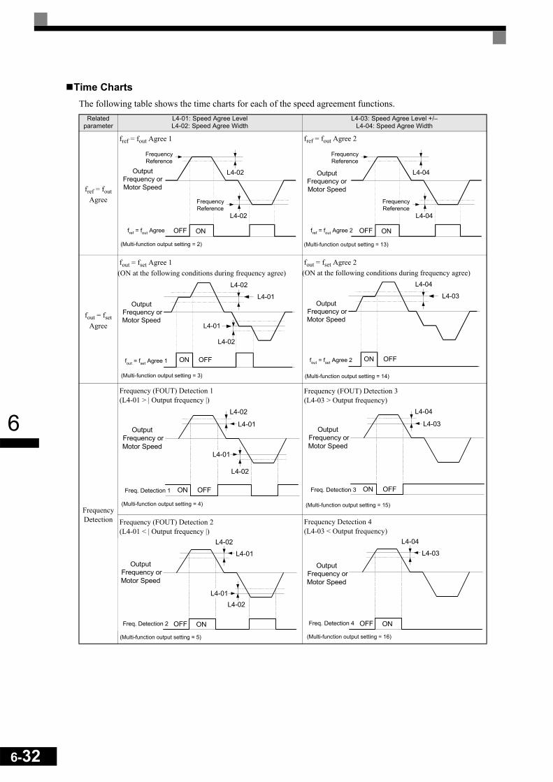
6-32
6
Time ChartsThe following table shows the time charts for each of the speed agreement functions.
Related parameter
L4-01: Speed Agree Level L4-02: Speed Agree Width
L4-03: Speed Agree Level +/–L4-04: Speed Agree Width
fref = fout Agree
fref = fout Agree 1 fref = fout Agree 2
fout = fset Agree
fout = fset Agree 1(ON at the following conditions during frequency agree)
fout = fset Agree 2(ON at the following conditions during frequency agree)
Frequency Detection
Frequency (FOUT) Detection 1 (L4-01 > | Output frequency |)
Frequency (FOUT) Detection 3 (L4-03 > Output frequency)
Frequency (FOUT) Detection 2 (L4-01 < | Output frequency |)
Frequency Detection 4 (L4-03 < Output frequency)
L4-02
L4-02
ONOFF
OutputFrequency orMotor Speed
fref = fout Agree
FrequencyReference
FrequencyReference
(Multi-function output setting = 2)
L4-04
L4-04
ONOFF
OutputFrequency orMotor Speed
fref = fout Agree 2
FrequencyReference
FrequencyReference
(Multi-function output setting = 13)
L4-01
L4-02
L4-01
L4-02
ON OFF
Output Frequency orMotor Speed
fout = fset Agree 1
(Multi-function output setting = 3)
L4-03
L4-04
ON OFF
Output Frequency orMotor Speed
fout = fset Agree 2
(Multi-function output setting = 14)
L4-01
L4-02
L4-01
L4-02
ON OFF
Output Frequency orMotor Speed
Freq. Detection 1
(Multi-function output setting = 4)
L4-03
L4-04
ON OFF
Output Frequency orMotor Speed
Freq. Detection 3
(Multi-function output setting = 15)
L4-01
L4-02
L4-01L4-02
ONOFF
Output Frequency orMotor Speed
Freq. Detection 2
(Multi-function output setting = 5)
L4-03
L4-04
ONOFF
Output Frequency orMotor Speed
Freq. Detection 4
(Multi-function output setting = 16)

6
Improving the Operation Performance
Reducing the Motor Speed Fluctuation (Slip Compensation Function)
When the load is large, the motor slip also grows and the motor speed decreases. The slip compensation func-tion keeps the motor speed constant, regardless of changes in load. When the motor is operating at the ratedload, parameter E2-02 (Motor Rated Slip) × the slip compensation gain value in parameter C3-01 is added tothe output frequency.
Related Parameters
* The factory setting will change when the control method is changed. (Open Loop Vector control factory settings are given.)
Adjusting Slip Compensation Gain (C3-01)The set value of C3-01 depends on the control method. The factory settings are:
• V/f control without PG: 0.0• Open Loop Vector control: 1.0
Set C3-01 to 1.0 to compensate the slip depending on the actual torque output status using the rated slip (E2-02/E4-02) as reference.
Adjust the slip compensation gain using the following procedure.
1. With Open Loop Vector control Set E2-02 (Motor Rated Slip) and E2-03 (Motor No-load Current) cor-rectly. The motor rated slip can be calculated using the values on the motor nameplate and the followingformula:
The motor data can be set automatically using the autotuning function.2. With V/f control set C3-01 to 1.0. 3. Apply a load, and measure the speed to adjust the slip compensation gain. Adjust the slip compensation
gain by 0.1 at a time only. If the speed is less than the target value, increase the slip compensation gain,and if the speed is higher than the target value, reduce the slip compensation gain.
4. Setting C3-01 to 0.0 disables the slip compensation function.
Parameter No. Name Factory
Setting
Change during Opera-
tion
Control Methods
V/f V/f with PG
Open Loop
Vector
Closed Loop
VectorC3-01 Slip compensation gain 1.0* Yes A No A No
C3-02 Slip compensation delay time 200 ms* No A No A No
C3-03 Slip compensation limit 200% No A No A No
C3-04 Slip compensation during regeneration 0 No A No A No
C3-05 Output voltage limit operation selection 0 No No No A A
Motor rated slip (Hz) Motor rated frequency (Hz) Rated motor speed (rpm) Number of motor poles×120
----------------------------------------------------------------------------------------------------------------------------–=
6-33

6-34
6
Adjusting Slip Compensation Primary Delay Time Constant (C3-02)The slip compensation delay time constant is set in ms.
The setting value of C3-02 depends on the control method. The factory settings are:• V/f control without PG: 2000 ms• Open loop vector control: 200 ms
Normally, there is no need to change these settings. When the slip compensation response is low, lower the setvalue. When the speed is unstable, increase the set value.
Adjusting Slip Compensation Limit (C3-03)Using parameter C3-03 the upper limit for the slip compensation can be set as a percentage, taking the motorrated slip as 100%.
If the speed is lower than the target value but does not change even after adjusting the slip compensation gain,the slip compensation limit may have reached. Increase the limit, and check the speed again. Always makesure that the value of the slip compensation limit and reference frequency does not exceed the tolerance of themachine.
The following diagram shows the slip compensation limit for the constant torque range and fixed output range.
Fig 6.38 Slip Compensation Limit
Selecting Slip Compensation Function During Regeneration (C3-04)Enables or disables the slip compensation function during regeneration.
If the slip compensation function operates during regeneration, you might have to use a braking option (brak-ing resistor, braking resistor unit and braking unit).
Operation Selection when Output Voltage Saturated (C3-05)Generally the Inverter cannot output a voltage that is higher than the input voltage. If the output voltage refer-ence for the motor (monitor parameter U1-06) exceeds the input voltage in the high-speed range, the outputvoltage becomes saturated, and inverter cannot respond to speed or load changes. This function automaticallyreduces the output voltage to avoid voltage saturation.Thereby the speed control accuracy can be maintained even at high speeds (around the rated speed of themotor). By the lowered voltage the current can be around 10% higher compared to the operation without volt-age limiter.
Slip compensation limit
Output frequency
E1-06: Base frequencyE1-04: Maximum output frequency

6
Torque Compensation for Sufficient Torque at Start and Low-speed Operation
The torque compensation function detects a rising motor load, and increases the output torque.
In V/f control the inverter calculates the motor primary loss voltage using the terminal resistance value (E2-05) and adjusts the output voltage (V) to compensate insufficient torque at startup and during low-speed oper-ation. The compensation voltage is calculated by the calculated Motor primary voltage loss × parameter C4-01.
In Open Loop Vector control the motor excitation current and the torque producing current are calculated andcontrolled separately. The torque compensation affects the torque producing current only.The torque producing current is calculated by the calculated torque reference × C4-01.
Related Parameters
* The factory setting will change when the control method is changed. (V/f control factory settings are given.)
Adjusting Torque Compensation Gain (C4-01)Normally, there is no need to change this setting. If adjustments are necessary do the following:
Open Loop Vector control:• If the torque response is slow increase the setting value.• If vibrations occur decrease the setting value.
V/f control:• If the cable is very long, increase the set value.• If the motor capacity is smaller than the Inverter capacity (max. applicable motor capacity), increase the
set value.• If the motor is vibrating, reduce the set value.
Setting precautions:• Adjust this parameter so that the output current during low-speed rotation does not exceed the Inverter
rated output current range.• Adjust the value in steps of 0.05 only.
Parameter No. Name Factory
Setting
Change during Opera-
tion
Control Methods
V/f V/f with PG
Open Loop
Vector
Closed Loop
VectorC4-01 Torque compensation gain 1.00 Yes A A A No
C4-02 Torque compensation delay time constant 200 ms* No A A A No
C4-03 Starting torque compensation value (forward direction) 0.0 No No No A No
C4-04 Starting torque compensation value (reverse direction) 0.0 No No No A No
C4-05 Starting torque compensation time constant 1 ms No No No A No
6-35

6-36
6
Adjusting the Torque Compensation Primary Delay Time Constant (C4-02)The setting value of C4-02 depends on the control method. The factory settings are:
• V/f control without PG: 200 ms• V/f control with PG: 200 ms• Open loop vector control: 20 ms
Normally, there is no need to change this setting. If adjustments are necessary do the following:• If the motor is vibrating, increase the set value.• If the torque response is slow, decrease the set value.
Starting Torque Compensation Function (C4-03 to C4-05)A starting torque compensation can be applied to speed up the torque establishment at start in Open Loop Vec-tor control.
This function is effective for machinery with large friction loads and applications, where high starting torqueis required. It works like shown in the following diagram.
Fig 6.39 Time Chart for Starting Torque Frequency
When this function is used, the following should be considered:• When the machine runs in FWD and REV direction both values, C4-03 and C4-04 have to be set.• The compensation works for motoring operation only. It can not be used for regenerative operation.• If the starting torque compensation is used and a large shock is generated at the start, increase the starting
torque compensation time constant (C4-05).
Automatic Speed Regulator (ASR)
In Closed Loop Vector control the automatic speed regulator (ASR) adjusts the torque reference in order toeliminate the deviation between the speed reference and the measured speed (PG feedback). Fig 6.40 showsthe ASR structure for Closed Loop Vector control.
Fig 6.40 ASR Structure for Closed Loop Vector Control
OFF
ONForward (Reverse) Run command
Time constant: C4-05Time constant: C4-02
C4-05 x 4
Torque compensationvolume
E1-09Output frequency
The larger value of b2-01 and E1-09
C4-03 (forward)C4-04 (reverse, negative polarity)
FrequencyReference
MotorSpeed
TorqueReference
P
I
+
-
+
+
C5-01/03
C5-02/04
TorqueLimits
DelayTimer
C5-06
C5-08I-Limit

6
In V/f control with PG the ASR adjusts the output frequency in order to eliminate the deviation between thespeed reference and the measured speed (PG feedback). Fig 6.41 shows the ASR structure for V/f control withPG.
Fig 6.41 ASR Structure for V/f control with PG
Related Parameters
* When the control method is changed, these values are reset to factory settings for the selected control mode. (The Closed Loop Vector control factory set-tings are given)
Multi-function Digital Inputs (H1-01 to H1-05)
V/f Control with/without PG Selection: “D”• When one of the digital inputs is set to “D” this input can be used to switch over to normal V/f control and
thereby to disable the ASR.• The ASR is disabled when the multifunction input is ON.
Speed Control Integral Disable: “E”• When one of the digital inputs is set to “E” this input can be used to switch the speed control between PI
and P control.• P control is active when the input is ON (Integral value is reset).
ASR Gain switching: “77”• When one of the digital inputs is set to “77” this input can be used to switch between the ASR P gains set
in C5-01 and C5-03.• If the input is enabled C5-03 will be used. If the input is disabled C5-01 will be used.
Parameter No. Name Factory
Setting
Change during Opera-
tion
Control Methods
V/f V/f with PG
Open Loop
Vector
Closed Loop
VectorC5-01 ASR proportional (P) gain 1 20.00 * Yes No A No A
C5-02 ASR integral (I) time 1 0.500 s * Yes No A No A
C5-03 ASR proportional (P) gain 2 20.00 * Yes No A No A
C5-04 ASR integral (I) time 2 0.500 s * Yes No A No A
C5-05 ASR limit 5.0% No No A No No
C5-06 ASR delay time 0.004 s No No No No A
C5-07 ASR switching frequency 0.0 Hz No No No No A
C5-08 ASR integral limit 400% No No No No A
F1-07 Integral value during accel/decel enable/disable 0 No No A No No
Set Value Function
Control Methods
V/fV/f with PG
Open Loop
Vector
Closed Loop
VectorD V/f control with/without PG selection No Yes No No
E Speed control integral operation disable No Yes No Yes
77 ASR proportional gain switch over No Yes No Yes
P
I
FrequencyReference
MotorSpeed
+
- + +
C5-01/03
C5-02/04
C5-05ASR Limit
OutputFrequency+ +
6-37

6-38
6
ASR Gain and Integral Time Adjustments for Closed Loop Vector Control
General Procedure1. Operate the motor at zero speed.2. Increase C5-01 (ASR proportional gain 1) to a level where no oscillation in the motor speed occurs.3. Decrease C5-04 (ASR integral time 2) to a level where no oscillation in the motor speed occurs.4. Increase the speed and observe the motor speed. If oscillations occur at any speed the gain must be
decreased and/or the integral time must be increased.5. If the speed is stable at all speeds the adjustment is completed.
Fine AdjustmentsWhen an even finer ASR adjustment is required, adjust the gain and integral time while observing the speedwaveform using the analog output terminals FM and AM. The necessary parameter settings are shown in thefollowing table.
The multi-function analog outputs have the following functions with these parameter settings.• Analog output 1 (terminal FM): Outputs frequency reference after the soft starter (Accel./decel. ramp and
S-curve) (0 to ±10 V).• Analog output 2 (terminal AM): Outputs actual motor speed (0 to ±10 V).
Adjusting ASR Proportional Gain 1 (C5-01)This gain adjusts the responsiveness of the speed control (ASR). The responsiveness is increased when thissetting is increased. Oscillation will occur if this setting is increased too much. See Fig 6.42 for details.
Adjusting ASR Integral Time 1 (C5-02)This parameter sets the speed control (ASR) integral time. Lengthening the integral time lowers the respon-siveness and the speed accuracy when the load changes suddenly. Oscillation can occur if this setting value istoo low. See Fig 6.42 for details.
Fig 6.42 Influence of the ASR Gain and Bias
Parameter Setting ExplanationH4-01 Analog output selection (terminal FM) 20
Settings that allow multi-function analog output 1 to be used to monitor the frequency reference after soft starter.H4-02 Analog output gain (terminal FM) 100%
H4-03 Analog output bias (terminal FM) 0.0%
H4-04 Analog output selection (terminal AM) 5Settings that allow multi-function analog output 2 to be used to
monitor the motor speed.H4-05 Analog output gain (terminal AM) 100%
H4-06 Analog output bias (terminal AM) 0.0%
H4-07 Analog output 1 signal level selection 1This setting allows a 0 to ± 10 V signal range to be monitored.
H4-08 Analog output 2 signal level selection 1
Time
If undershooting occurs:Decrease C5-03 and/or increase C5-04
If overshooting occurs:Decrease C5-01 and/or increase C5-02
Motor speed

6
Different Gain Settings for Low-speed and High-speedSwitch between low-speed and high-speed gain when oscillation occurs because of resonance with themechanical system at low speed or high speed. The gain and integral time can be switched according to themotor speed, as shown in Fig 6.43.
Fig 6.43 Low-speed and High-speed Gain Settings
If C5-07 is set to 0, the gain in C5-01 and the integral time in C5-02 are used for the whole speed range.
Setting the Gain Switching Frequency (C5-07)Set the switching frequency to about 80% of the motor operating frequency or the frequency at which oscilla-tion occurs.
Low-speed Gain Adjustments (C5-03, C5-04)Connect the actual load and adjust these parameters at zero-speed. Increase C5-03 (ASR gain 2) and decreaseC5-04 (ASR integral time 2) as long as no oscillation occurs.
High-speed Gain Adjustments (C5-01, C5-02)Adjust these parameters at normal operating speed. Increase C5-01 (ASR gain 1) and decrease C5-02 (ASRintegral time 1) as long as no oscillation occurs.
ASR Proportional Gain Switch Setting Using a Digital InputWhen one of the digital inputs (H1-01 to H1-05) is set to 77, the input can be used to switch between C5-01(ASR gain 1) and C5-03 (ASR gain 2). ASR gain 1 is used when the multi-function input is OFF, ASR gain 2is used when the input is ON. This input has higher priority than the ASR switching frequency set in C5-07.The gain is changed linearly using the integral time 1. See Fig 6.44 for details.
Fig 6.44 ASR Gain Switching by Digital Input
P,I
0 C5-07
P=C5-03I=C5-04
P=C5-01I=C5-02
MotorSpeed
ASR gain switchdigital input
ONOFF
C5-02 C5-02
ASR gain C5-01 value
C5-03 value
6-39

6-40
6
ASR Gain and Integral Time Adjustments for V/f control with PGWhen using V/f control with PG, set the ASR gain and the integral time at E1-09 (minimum output frequency)and E1-04 (maximum output frequency). See Fig 6.45 for details.
Fig 6.45 Speed Control Gain Integral Time Adjustment for V/f Control with PG
Gain Adjustments at Minimum Output Frequency (C5-03 and C5-04)Operate the motor at the minimum output frequency. Increase C5-03 (ASR proportional gain 2) and decreaseC5-04 (ASR integral time 2) as long as no oscillation occurs.Monitor the Inverter's output current and verify that it is less than 50% of the Inverter rated current. If the out-put current exceeds 50% of the Inverter's rated current, decrease C5-03 and increase C5-04.
Gain Adjustments at Maximum Output Frequency (C5-01 and C5-02)Operate the motor at the maximum output frequency. Increase C5-01 (ASR proportional gain 1) and decreaseC5-02 (ASR integral time 1) as long as no oscillation occurs.
Fine AdjustmentsWhen an even finer ASR adjustment is required, adjust the gain while observing the motor speed. The adjust-ment procedure is the same as for vector control.
Using Integral Control during Acceleration and Deceleration (F1-07)Enable integral operation during acceleration and deceleration (by setting F1-07 to 1) if the motor speed has tofollow the frequency reference closely during acceleration and deceleration. Reduce the setting of C5-01 ifovershooting occurs during acceleration, and reduce the setting of C5-03 and increase the setting of C5-04 ifundershooting occurs when stopping. If overshooting and undershooting cannot be eliminated by adjustingonly the gain and integral time, reduce the ASR limit value (C5-05).
P,I
0 Motor Speed
P=C5-03I=C5-04
P=C5-01I=C5-02
E1-09Min. OutputFrequency
E1-04Max. OutputFrequency
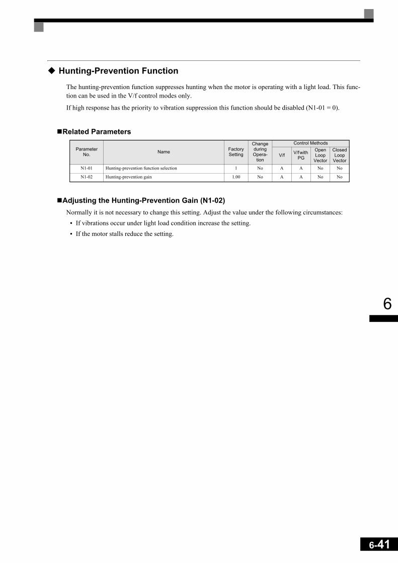
6
Hunting-Prevention Function
The hunting-prevention function suppresses hunting when the motor is operating with a light load. This func-tion can be used in the V/f control modes only.
If high response has the priority to vibration suppression this function should be disabled (N1-01 = 0).
Related Parameters
Adjusting the Hunting-Prevention Gain (N1-02)Normally it is not necessary to change this setting. Adjust the value under the following circumstances:
• If vibrations occur under light load condition increase the setting.• If the motor stalls reduce the setting.
Parameter No. Name Factory
Setting
Change during Opera-
tion
Control Methods
V/f V/f with PG
Open Loop
Vector
Closed Loop
VectorN1-01 Hunting-prevention function selection 1 No A A No No
N1-02 Hunting-prevention gain 1.00 No A A No No
6-41

6-42
6
Stabilizing Speed (Automatic Frequency Regulator)
The speed feedback detection control (AFR) function controls the stability of the speed when a load is sud-denly applied or removed. It calculates the amount of speed fluctuation using the torque current (Iq) feedbackvalue and compensates the output frequency with the amount of fluctuation.
Fig 6.46 AFR Control Loop
Related Parameters
Setting the AFR Gain (N2-01)Normally there is no need to change this setting. If adjustments are necessary do the following:
If hunting occurs increase N2-01.
If the response is too low, decrease N2-01.
Adjust the setting by 0.05 at a time while checking the response.
Setting the AFR Time Constants 1 and 2 (N2-02, N2-03)Normally the setting value of N2-02 is used as AFR time constant (T in Fig 6.46). The setting value of N2-03is used when:
L2-04 is set to 1 or 2 AND
output frequency > 5 Hz AND
a transient load change occurs (causing transient regeneration or overshoot at acceleration).
Generally there is no need to change the settings.
Parameter No. Name Factory
Setting
Change during Opera-
tion
Control Methods
V/f V/f with PG
Open Loop
Vector
Closed Loop
VectorN2-01 Speed feedback detection control (AFR) gain 1.00 No No No A No
N2-02 Speed feedback detection control (AFR) time constant 50 ms No No No A No
N2-03 Speed feedback detection control (AFR) time constant 2 750 ms No No No A No
Iq
foutfref

6
Machine Protection
Limiting Motor Torque (Torque Limit Function)
This function allows limitation of motor shaft torque independently for each of the four quadrants. The torquelimit can be set as fixed value using parameters or as variable value using an analog input. The torque limitfunction can be used with Open Loop Vector and Closed Loop Vector control only.
Related Parameters
* A setting value of 100% is equal to the motor rated torque.
Multi-function Output (H2-01 to H2-03)
Setting the Torque Limit Using ParametersUsing L7-01 to L7-04, four torque limits in the following directions can be set individually: Forward drive,reverse drive, forward regenerative and reverse regenerative (see Fig 6.47)
Fig 6.47 Torque Limit Parameters
Using a Digital Output to Signalize Operation at the Torque LimitIf a multifunction output is set for this function (H2-01 to H2-03 is set to “30”), the output is switched ONwhen the motor output torque reaches one of the torque limits.
Parameter No. Name Factory
Setting
Change during Opera-
tion
Control Methods
V/f V/f with PG
Open Loop
Vector
Closed Loop
VectorL7-01 Forward drive torque limit 200%* No No No A A
L7-02 Reverse drive torque limit 200%* No No No A A
L7-03 Forward regenerative torque limit 200%* No No No A A
L7-04 Reverse regenerative torque limit 200%* No No No A A
L7-06 Torque limit time constant 200 ms No No No A No
L7-07 Torque limit operation during accel./decel. 0 No No No A No
Set Value Function
Control Methods
V/fV/f
with PG
Open Loop
Vector
Closed Loop
Vector30 During torque limit No No Yes Yes
L7-01
Output Torque
Output Speed
L7-03L7-02
L7-04
ForwardDrive
ReverseDrive
ReverseRegenerative
ForwardRegenerative
6-43
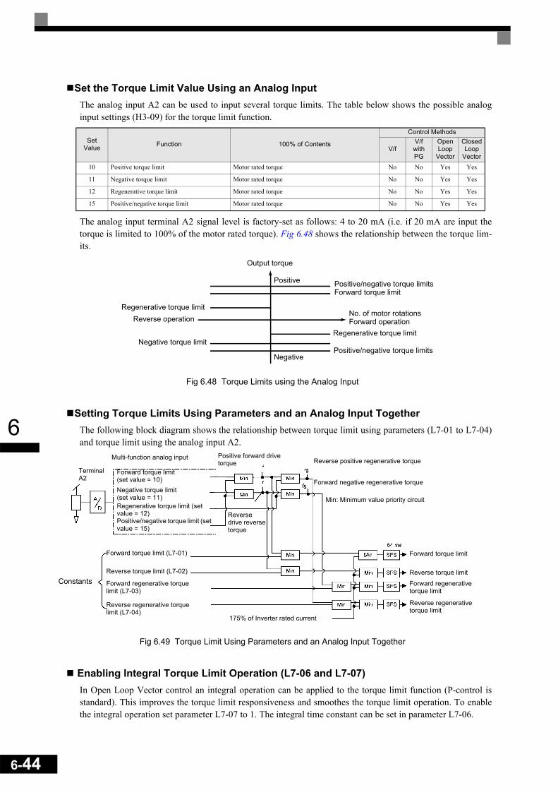
6-44
6
Set the Torque Limit Value Using an Analog InputThe analog input A2 can be used to input several torque limits. The table below shows the possible analoginput settings (H3-09) for the torque limit function.
The analog input terminal A2 signal level is factory-set as follows: 4 to 20 mA (i.e. if 20 mA are input thetorque is limited to 100% of the motor rated torque). Fig 6.48 shows the relationship between the torque lim-its.
Fig 6.48 Torque Limits using the Analog Input
Setting Torque Limits Using Parameters and an Analog Input TogetherThe following block diagram shows the relationship between torque limit using parameters (L7-01 to L7-04)and torque limit using the analog input A2.
Fig 6.49 Torque Limit Using Parameters and an Analog Input Together
Enabling Integral Torque Limit Operation (L7-06 and L7-07)In Open Loop Vector control an integral operation can be applied to the torque limit function (P-control isstandard). This improves the torque limit responsiveness and smoothes the torque limit operation. To enablethe integral operation set parameter L7-07 to 1. The integral time constant can be set in parameter L7-06.
Set Value Function 100% of Contents
Control Methods
V/fV/f with PG
Open Loop
Vector
Closed Loop
Vector10 Positive torque limit Motor rated torque No No Yes Yes
11 Negative torque limit Motor rated torque No No Yes Yes
12 Regenerative torque limit Motor rated torque No No Yes Yes
15 Positive/negative torque limit Motor rated torque No No Yes Yes
Output torque
Positive Positive/negative torque limitsForward torque limit
Regenerative torque limitReverse operation
No. of motor rotationsForward operation
Regenerative torque limitNegative torque limit
Positive/negative torque limitsNegative
Multi-function analog input
Terminal A2
Forward torque limit (set value = 10)Negative torque limit (set value = 11)Regenerative torque limit (set value = 12)Positive/negative torque limit (set value = 15)
Positive forward drive torque Reverse positive regenerative torque
Forward negative regenerative torque
Reverse drive reverse torque
Min: Minimum value priority circuit
Constants
Forward torque limit (L7-01)
Reverse torque limit (L7-02)
Forward regenerative torque limit (L7-03)
Reverse regenerative torque limit (L7-04)
175% of Inverter rated current
Forward torque limit
Reverse torque limit
Forward regenerative torque limit
Reverse regenerative torque limit

6
Setting Precautions• When the output torque reaches the torque limit, control and compensation of the motor speed is disabled
to prevent the output torque from exceeding the torque limit. The torque limit has the priority.• When using the torque limit for hoist applications, do not carelessly lower the torque limit value, as this
may result in motor stalling.• When using an analog input for torque limit setting, an analog input value of 10 V/20 mA is equal to a
torque limit of 100% of the motor rated torque. To raise the torque limit value at an analog input of 10 V/20 mA for instance to 150% of the rated torque, set the input terminal gain to 150.0 (%). Adjust the gainfor multi-function analog input terminal A2 using H3-10.
• The torque limit accuracy is ±5% at an output frequency of 10 Hz or above. When output frequency islower than 10 Hz, the accuracy is lowered.
Preventing Motor Stalling During Operation
Stall prevention during operation prevents the motor from stalling by automatically lowering the inverter out-put frequency when a transient overload occurs while the motor is operating at a constant speed.
Stall prevention during operation can be enabled in V/f control with/without PG only. If the Inverter outputcurrent continues to exceed the setting in parameter L3-06 for 100 ms or longer, the motor speed is reduced.Enable or disable the stall prevention using parameter L3-05. Set the according deceleration times using C1-02 (Deceleration time 1) or C1-04 (Deceleration Time 2).
If the Inverter output current reaches the set value in L3-06 – 2%, the motor will accelerate again to the set fre-quency.
Related Parameters
* The initial value when C6-01 is set to 0 is given. If C6-01 is set to 1 or 2, the initial value will be 120%.
Changing Stall Prevention Level during Operation Using an Analog InputIf H3-09 (Analog Input A2 Function Selection) is set to 8 (stall prevention during operation level), the stalllevel during operation can be changed using the analog input A2.In this case the function uses either the value from the multi-function analog input terminal A2 input level orthe set value in parameter L3-06. The lower value of both will be used as stall prevention level.
Fig 6.50 Stall Prevention Level during Operation Using an Analog Input
If the motor capacity is smaller than the Inverter capacity or the motor stalls when operating at the factory set-tings, lower the stall prevention level during operation.
Parameter No. Name Factory
Setting
Change during Opera-
tion
Control Methods
V/f V/f with PG
Open Loop
Vector
Closed Loop
VectorL3-05 Stall prevention selection during running function selection 1 No A A No No
L3-06 Stall prevention level during running 150% * No A A No No
Stall prevention level during operation
Multi-function analog inputterminal A2 input level
6-45

6-46
6
Motor Torque Detection
If an excessive load is applied to the machinery (overtorque) or the load drops suddenly (undertorque), analarm signal can be output to one of the digital output terminals M1-M2, M3-M4, or M5-M6.
To use the overtorque/undertorque detection function, set B, 17, 18, 19 (overtorque/undertorque detectionNO/NC) in one of the parameter H2-01 to H2-03 (digital output terminals M1-M2, M3-M4, and M5-M6 func-tion selection).
Overtorque/undertorque is detected by:• observing the output current in V/f control with or without PG (the inverter rated output current is equal to
100%).• observing the torque reference value in Open Loop and Closed Loop Vector control (the motor rated
torque is equal to 100%).
Related Parameters
Multi-function Output (H2-01 to H2-03)
Multi-Function Analog Input (H3-09)
Parameter No. Name Factory
Setting
Change during Opera-
tion
Control Methods
V/f V/f with PG
Open Loop
Vector
Closed Loop
VectorL6-01 Torque detection selection 1 0 No A A A A
L6-02 Torque detection level 1 150% No A A A A
L6-03 Torque detection time 1 0.1 s No A A A A
L6-04 Torque detection selection 2 0 No A A A A
L6-05 Torque detection level 2 150% No A A A A
L6-06 Torque detection time 2 0.1 s No A A A A
Set Value Function
Control Methods
V/fV/f with PG
Open Loop
Vector
Closed Loop
Vector
B Overtorque/undertorque detection 1 NO(NO contact: Overtorque detection and undertorque detection enabled when contact is ON) Yes Yes Yes Yes
17 Overtorque/undertorque detection 1 NC(NC contact: Overtorque detection and undertorque detection enabled when contact is OFF) Yes Yes Yes Yes
18 Overtorque/undertorque detection 2 NO(NO contact: Overtorque detection and undertorque detection enabled when contact is ON) Yes Yes Yes Yes
19 Overtorque/undertorque detection 2 NC(NC contact: Overtorque detection and undertorque detection enabled when contact is OFF) Yes Yes Yes Yes
Set Value Function 100% of Contents
Control Methods
V/fV/f with PG
Open Loop
Vector
Closed Loop
Vector
7 Overtorque/Undertorque Detection Level Motor rated torque (vector control), Inverter rated current (V/f control) Yes Yes Yes Yes

6
L6-01 and L6-04 Set Values and Operator DisplayThe relationship between alarms displayed on the digital operator when overtorque or undertorque is detected,and the set values in L6-01 and L6-04, is shown in the following table.
Timing ChartsFig 6.51 and Fig 6.52 show the timing charts for overtorque and undertorque detection.
Fig 6.51 Overtorque Detection
Fig 6.52 Undertorque Detection
Set Value Function
Operator DisplayOvertorque/ Undertorque Detection 1
Overtorque/ Undertorque Detection 2
0 Overtorque/undertorque detection disabled. – –
1 Overtorque detection only with speed agree; operation continues (warning is output). OL3 flashes OL4 flashes
2 Overtorque detected continuously during operation; operation continues (warning is output). OL3 flashes OL4 flashes
3 Overtorque detection only with speed agree; output is stopped upon detection. OL3 lights up OL4 lights up
4 Overtorque detected continuously during operation; output is stopped upon detection. OL3 lights up OL4 lights up
5 Undertorque detection only with speed agree; operation continues (warning is output). UL3 flashes UL4 flashes
6 Undertorque detected continuously during operation; operation continues (warning is output). UL3 flashes UL4 flashes
7 Undertorque detection only with speed matching; output is stopped upon detection. UL3 lights up UL4 lights up
8 Undertorque detected continuously during operation; output is stopped upon detection. UL3 lights up UL4 lights up
Motor current (output torque)
L6-02 or L6-05
Overtorque detection 1 NOor overtorque detection 2 NO
*Overtorque detection switch off bandwidth is approximately 10% of the Inverter rated output current (or motor rated torque).
L6-03 or L6-06 L6-03 or L6-06
Motor current (output torque)
L6-02 or L6-05
L6-03 orL6-06L6-03 or
L6-06Undertorque detection 1 NOor undertorque detection 2 NO
* Undertorque detection switch off bandwidth is approximately 10% of the Inverter rated output current (or motor rated torque).
6-47

6-48
6
Changing Overtorque and Undertorque Detection Levels Using an Analog InputIf parameter H3-09 (Analog Input A2 Function Selection) is set to 7 (overtorque/undertorque detection level),the overtorque/undertorque detection level can be changed using the analog input A2 (refer to Fig 6.53).
Only the overtorque/undertorque detection level 1 can be changed using the analog input. Overtorque/under-torque detection level 2 cannot be changed by an analog input signal.
Fig 6.53 Overtorque/Undertorque Detection Level Using an Analog Input
Motor Overload Protection
The motor can be protected from overload using the built-in electronic thermal overload relay function.
Related Parameters
* Factory settings depend on Inverter capacity. (The values shown are for a 200 V Class Inverter with 0.4 kW.)
Multi-Function Outputs (H2-01 to H2-03)
Setting Motor Rated Current (E2-01 and E4-01)Set the rated current value on the motor nameplate in parameters E2-01 (for motor 1) and E4-01 (for motor 2).This set value is the base current for the internal thermal overload calculation.
Parameter No. Name Factory
Setting
Change during Opera-
tion
Control Methods
V/f V/f with PG
Open Loop
Vector
Closed Loop
Vector
E2-01 Motor rated current 1.90 A* No Q Q Q Q
E4-01 Motor 2 rated current 1.90 A* No A A A A
L1-01 Motor protection selection 1 No Q Q Q Q
L1-02 Motor protection time constant 1.0 min No A A A A
Set Value Function
Control Methods
V/fV/f with PG
Open Loop
Vector
Closed Loop
Vector1F Motor overload (OL1, including OH3) pre-alarm (ON: 90% or more of the detection level) Yes Yes Yes Yes
(4 mA)
Detection level
Multi-function analog inputterminal A2 input level
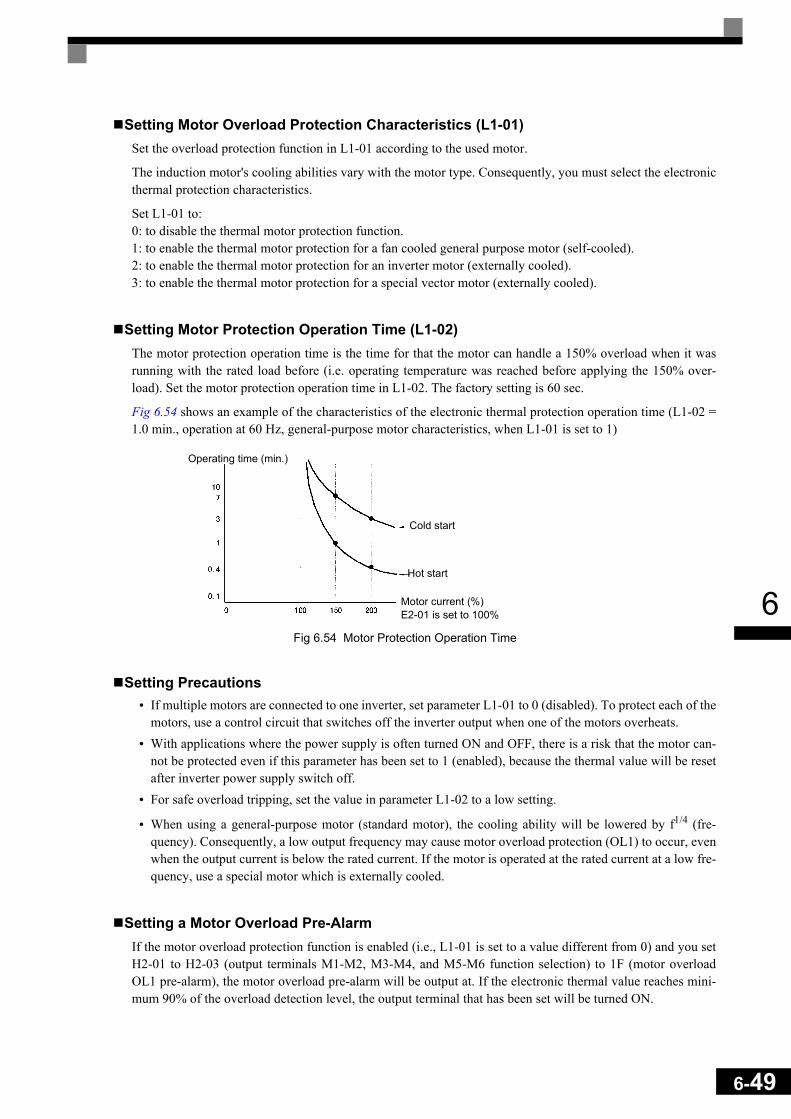
6
Setting Motor Overload Protection Characteristics (L1-01)Set the overload protection function in L1-01 according to the used motor.
The induction motor's cooling abilities vary with the motor type. Consequently, you must select the electronicthermal protection characteristics.
Set L1-01 to:0: to disable the thermal motor protection function.1: to enable the thermal motor protection for a fan cooled general purpose motor (self-cooled).2: to enable the thermal motor protection for an inverter motor (externally cooled).3: to enable the thermal motor protection for a special vector motor (externally cooled).
Setting Motor Protection Operation Time (L1-02)The motor protection operation time is the time for that the motor can handle a 150% overload when it wasrunning with the rated load before (i.e. operating temperature was reached before applying the 150% over-load). Set the motor protection operation time in L1-02. The factory setting is 60 sec.
Fig 6.54 shows an example of the characteristics of the electronic thermal protection operation time (L1-02 =1.0 min., operation at 60 Hz, general-purpose motor characteristics, when L1-01 is set to 1)
Fig 6.54 Motor Protection Operation Time
Setting Precautions• If multiple motors are connected to one inverter, set parameter L1-01 to 0 (disabled). To protect each of the
motors, use a control circuit that switches off the inverter output when one of the motors overheats.• With applications where the power supply is often turned ON and OFF, there is a risk that the motor can-
not be protected even if this parameter has been set to 1 (enabled), because the thermal value will be resetafter inverter power supply switch off.
• For safe overload tripping, set the value in parameter L1-02 to a low setting.
• When using a general-purpose motor (standard motor), the cooling ability will be lowered by f1/4 (fre-quency). Consequently, a low output frequency may cause motor overload protection (OL1) to occur, evenwhen the output current is below the rated current. If the motor is operated at the rated current at a low fre-quency, use a special motor which is externally cooled.
Setting a Motor Overload Pre-AlarmIf the motor overload protection function is enabled (i.e., L1-01 is set to a value different from 0) and you setH2-01 to H2-03 (output terminals M1-M2, M3-M4, and M5-M6 function selection) to 1F (motor overloadOL1 pre-alarm), the motor overload pre-alarm will be output at. If the electronic thermal value reaches mini-mum 90% of the overload detection level, the output terminal that has been set will be turned ON.
Operating time (min.)
Cold start
Hot start
Motor current (%)E2-01 is set to 100%
6-49
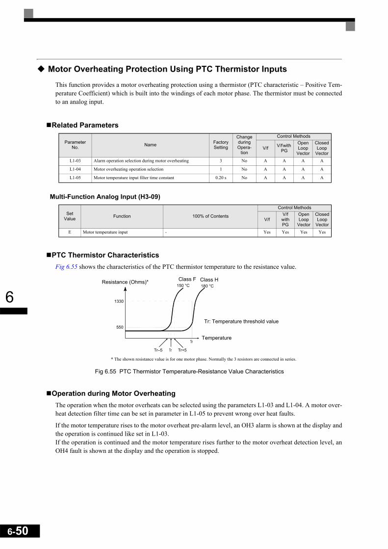
6-50
6
Motor Overheating Protection Using PTC Thermistor Inputs
This function provides a motor overheating protection using a thermistor (PTC characteristic – Positive Tem-perature Coefficient) which is built into the windings of each motor phase. The thermistor must be connectedto an analog input.
Related Parameters
Multi-Function Analog Input (H3-09)
PTC Thermistor CharacteristicsFig 6.55 shows the characteristics of the PTC thermistor temperature to the resistance value.
Fig 6.55 PTC Thermistor Temperature-Resistance Value Characteristics
Operation during Motor OverheatingThe operation when the motor overheats can be selected using the parameters L1-03 and L1-04. A motor over-heat detection filter time can be set in parameter in L1-05 to prevent wrong over heat faults.
If the motor temperature rises to the motor overheat pre-alarm level, an OH3 alarm is shown at the display andthe operation is continued like set in L1-03.If the operation is continued and the motor temperature rises further to the motor overheat detection level, anOH4 fault is shown at the display and the operation is stopped.
Parameter No. Name Factory
Setting
Change during Opera-
tion
Control Methods
V/f V/f with PG
Open Loop
Vector
Closed Loop
VectorL1-03 Alarm operation selection during motor overheating 3 No A A A A
L1-04 Motor overheating operation selection 1 No A A A A
L1-05 Motor temperature input filter time constant 0.20 s No A A A A
Set Value Function 100% of Contents
Control Methods
V/fV/f with PG
Open Loop
Vector
Closed Loop
VectorE Motor temperature input - Yes Yes Yes Yes
Resistance (Ohms)* Class F Class H
Tr: Temperature threshold value
Temperature
* The shown resistance value is for one motor phase. Normally the 3 resistors are connected in series.

6
Terminal ConnectionThe terminal connection for the motor overheat function is shown in Fig 6.56. The following points have to beconsidered:
• Pin 2 of the DIP-switch S1 on the control terminal board has to be turned to OFF for A2 voltage input. Thefactory setting is ON (A2 current input).
• Parameter H3-09 has to be set to “E”• Parameter H3-08 (analog input terminal A2 signal level) has to be set to 0 (0-10V input).
Fig 6.56 Terminal Connections for Motor Overheating Protection
Limiting Motor Rotation Direction and Output Phase Rotation
If the motor reverse rotation is prohibited, a reverse run command will not be accepted, even if it is input. Usethis setting for applications in which reverse motor rotation can cause problems (e.g., fans, pumps, etc.)
In V/F mode it is also possible to change the output phase order by changing a parameter. This is much easierand faster than changing the wiring if the motor rotational direction is wrong. If this function is used a prohibi-tion of reverse direction is not possible.
Related Parameters
Param-eter
NumberName Description Setting
RangeFactory Setting
Change during Opera-
tion
Control Methods
V/fV/f with PG
Open Loop
Vector
Closed Loop
Vector
b1-04 Prohibition of reverse operation
0: Reverse enabled1: Reverse disabled 0 or 2 0 No
A A A A
2: Output Phase Rotation A No No No
+V (15V, 20mA)
A2 , 0-10V
AC
Branch resistance18kOhm*
PTC thermistor
MA
MBMC
M1
M2
M3
M4
M5
M6
*1The resistance value of 18 kΩ is only valid when a 3-phase PTC with the characteristic shown on the previous page is used.
6-51

6
Automatic Restart
This section explains functions for continuing or automatically restarting inverter operation after a momentarypower loss.
Restarting Automatically After Momentary Power Loss
If a temporary power loss occurs, the inverter can be restarted automatically to continue motor operation.
To restart the Inverter after the power has returned, set L2-01 to 1 or 2.
If L2-01 is set to 1, the inverter will restart as long as the power is recovered within the time set in L2-02. Ifthe power loss time exceeds the time set in L2-02, an UV1 alarm (DC bus undervoltage) will be detected.
If L2-01 is set to 2, the inverter will restart, when the main power supply is recovered as long as the controlpower supply (i.e., power supply to the control circuit) is maintained. Consequently, alarm UV1 (DC bus und-ervoltage) will not be detected.
Related Parameters
* 1. Factory settings depend on Inverter capacity. (The values shown are for a 200 V Class Inverter for 0.4 kW.)* 2. These values are for a 200 V Class Inverter. For a 400 V Class Inverter, double the values.
Setting Precautions• Error output signals are not output during momentary power loss recovery.• To continue Inverter operation after the power has been restored, make the settings so that RUN com-
mands from the control main circuit terminal are stored even while power is suspended.• If the momentary power loss operation selection is set to 0 (Disabled), an alarm UV1 (main circuit under-
voltage) will be detected when the momentary power loss exceeds 15 ms during operation.
Parameter No. Name Factory
Setting
Change during Opera-
tion
Control Methods
V/f V/f with PG
Open Loop
Vector
Closed Loop
VectorL2-01 Momentary power loss detection 0 No A A A A
L2-02 Momentary power loss ride through time 0.1 s*1 No A A A A
L2-03 Min. baseblock (BB) time 0.1 s No A A A A
L2-04 Voltage recovery time 0.3 s*1 No A A A A
L2-05 Undervoltage (UV) detection level 190 V*2 No A A A A
6-52
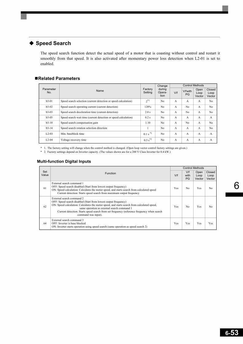
6
Speed Search
The speed search function detect the actual speed of a motor that is coasting without control and restart itsmoothly from that speed. It is also activated after momentary power loss detection when L2-01 is set toenabled.
Related Parameters
* 1. The factory setting will change when the control method is changed. (Open loop vector control factory settings are given.)* 2. Factory settings depend on Inverter capacity. (The values shown are for a 200 V Class Inverter for 0.4 kW.)
Multi-function Digital Inputs
Parameter No. Name Factory
Setting
Change during Opera-
tion
Control Methods
V/f V/f with PG
Open Loop
Vector
Closed Loop
Vector
b3-01 Speed search selection (current detection or speed calculation) 2*1 No A A A No
b3-02 Speed search operating current (current detection) 120% No A No A No
b3-03 Speed search deceleration time (current detection) 2.0 s No A No A No
b3-05 Speed search wait time (current detection or speed calculation) 0.2 s No A A A A
b3-10 Speed search compensation gain 1.10 No A No A No
b3-14 Speed search rotation selection direction 1 No A A A No
L2-03 Min. baseblock time 0.1 s *1 No A A A A
L2-04 Voltage recovery time 0.3 s*2 No A A A A
Set Value Function
Control Methods
V/fV/f
with PG
Open Loop
Vector
Closed Loop
Vector
61
External search command 1OFF: Speed search disabled (Start from lowest output frequency)ON: Speed calculation: Calculates the motor speed, and starts search from calculated speed Current detection: Starts speed search from maximum output frequency
Yes No Yes No
62
External search command 2OFF: Speed search disabled (Start from lowest output frequency)ON: Speed calculation: Calculates the motor speed, and starts search from calculated speed, same operation as external search command 1 Current detection: Starts speed search from set frequency (reference frequency when search command was input).
Yes No Yes No
64External search command 3OFF: Inverter is base blockedON: Inverter starts operation using speed search (same operation as speed search 2)
Yes Yes Yes Yes
6-53

6-54
6
Setting Precautions• When both external search commands 1 and 2 are set for the multi-function contact terminals, an OPE03
(invalid multi-function input selection) operation error will occur. Set either external search command 1 orexternal search command 2.
• If speed search during startup is selected when using V/f control with PG or Closed Loop Vector controlthe unit will start from the frequency detected by PG.
• If performing speed search using external search commands, design the control circuit so that the run com-mand and external search command are both ON. These two commands must be kept on, at least for thetime set in parameter L2-03.
• If the Inverter output is equipped with a contactor, set the contactor operation delay time in the SpeedSearch Wait Time (b3-05). The factory setting is 0.2 s. When not using a contactor, you can reduce thesearch time to 0.0 s. After waiting for the speed search wait time, the Inverter starts the speed search.
• Parameter b3-02 (current detection level for search completion) is effective only when current detectionspeed search is selected. When the current falls below the detection level, the speed search is supposed tobe as completed, and the motor accelerates or decelerates to the set frequency.
• If an overcurrent (OC) is detected when using speed search after power recovery, lengthen the MinimumBaseblock Time (L2-03).
Application Precautions for Speed Searches Using Estimated Speed • When using V/f control with or without a PG, always perform stationary autotuning for line-to-line resis-
tance before using speed searches based on calculated speeds.• When using Open Loop or Closed Loop Vector control, always perform rotational autotuning before using
speed searches based on calculated speeds.• If the cable length between the motor and Inverter is changed after autotuning has been performed, per-
form stationary autotuning for line-to-line resistance again.
Speed Search SelectionThe speed search method can be selected using b3-01. If b3-01 is set to 0 the search method is speed calcula-tion. It has to be activated by a multi-function input (H1- set to 61 or 62).If b3-01 is set to 1, the search method is speed calculation too, but speed search is performed at every RUNcommand and has not to be activated by a multifunction input.The same is valid for setting b3-01 to 2 or 3, only the search method is current detection instead of speed cal-culation.Refer to the table below to see the differences of both search methods.
Search Name Speed Calculation Current Detection
Search MethodCalculates the motor speed when the search starts, and accel-erates or decelerates from the calculated speed to the set fre-quency. The direction of motor rotation is also detected.
Starts speed search from the frequency when the temporary power loss was detected, or from the highest frequency, and performs speed detection by watching the current level dur-ing the search.
External Speed Search Com-mand
External search command 1 and external search command 2 become the same operation calculation of the motor speed and starting the search from the calculated speed.
External speed search command 1:Starts speed search from the maximum output frequency.External speed search command 2:Starts speed search from the frequency reference set before the search command.
Application PrecautionsCannot be used with multi-motor drives, with motors two or more sizes smaller than the Inverter capacity, and high-speed motors (higher than 130 Hz)
In control method without PG, the motor may accelerate suddenly with light loads.

6
Speed Calculation
Search at StartupThe time chart for when speed search at startup and speed search to multi-function input terminals is shownbelow.
Fig 6.57 Speed Search at Startup (Calculated Speed)
Speed Search after Power Loss• Loss Time shorter than the Minimum Baseblock Time (L2-03)
Fig 6.58 Speed Search after Power Loss with Loss Time < L2-03
• Loss Time longer than the Minimum Baseblock Time (L2-03)
Fig 6.59 Speed Search after Power Loss with Loss Time > L2-03
OFF ONRun command
Output frequency
Output current
0.7 to 1.0 s
Minimum baseblock time (L2-03) x 0.7*
Deceleration time set in b3-03
b3-02
*Lower limit set using Speed Search Wait Time (b3-05)
Set frequency refer-ence
Note:If the stopping method is set to coast to stop, and the run command turns ON in a short time, the operation may be the same as the search in case 2.
Starts usingcalculated speed
AC power supply ON OFF
Output current
Minimum baseblock time (L2-03) x 0.75
10 ms
Start usingspeed detected
Set frequencyreference
After AC power supply recovery, the inverter waits for the minimum Speed Search Wait Time (b3-05).
Output frequency
Set frequencyreference
Minimum baseblock time(L2-03)
Speed Search Wait Time(b3-05)
Note: If the frequency immediately before the baseblock is low or the power supply break time is long, operation may be the same as the search in case 1.
AC power supply ON OFF
Output frequency
Output current
Start using speed detected
10 ms
6-55

6-56
6
Current Detection
Speed Search at StartupThe time chart when speed search at startup or external speed search command is selected is shown below.
Fig 6.60 Speed Search at Startup (Current Detection)
Speed Search after Power Loss• Loss time shorter than minimum baseblock time
Fig 6.61 Speed Search after Power Loss Time < L2-03
• Loss time longer than minimum baseblock time
Fig 6.62 Speed Search after Power Loss with Loss Time > L2-03
OFF ONRun command
Output frequency
Output current
* Lower limit is set using Speed Search Time (b3-05).
Deceleration time set in b3-03
b3-02
Set frequency ref-erenceMaximum output
frequency or set frequency
Minimum baseblock time*(L2-03)
OFFONAC power supply
Output frequency
Output current
Set frequency ref-erence
Minimum baseblock time (L2-03)*1
*2
Output frequency before power loss
speed search operating current
Deceleration time set in b3-03
*1Baseblock time may be reduced by the output frequency immediately before baseblock.*2After AC power supply recovery, the inverter waits for the minimum Speed Search Wait Time (b2-03).
b3-02
Minimum baseblock time(L2-03)
OFFONAC power supply
Output frequency
Output current
Set frequency ref-erence
Speed search operating timeb3-02
Deceleration speed set in b3-03
Output frequency before power loss
Speed search wait time (b3-05)
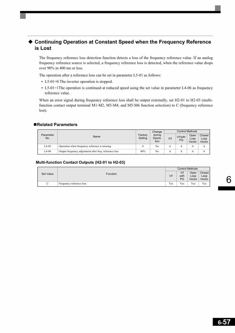
6
Continuing Operation at Constant Speed when the Frequency Reference is Lost
The frequency reference loss detection function detects a loss of the frequency reference value. If an analogfrequency reference source is selected, a frequency reference loss is detected, when the reference value dropsover 90% in 400 ms or less.
The operation after a reference loss can be set in parameter L5-01 as follows:• L5-01=0 The inverter operation is stopped.• L5-01=1The operation is continued at reduced speed using the set value in parameter L4-06 as frequency
reference value.
When an error signal during frequency reference loss shall be output externally, set H2-01 to H2-03 (multi-function contact output terminal M1-M2, M3-M4, and M5-M6 function selection) to C (frequency referencelost).
Related Parameters
Multi-function Contact Outputs (H2-01 to H2-03)
Parameter No. Name Factory
Setting
Change during Opera-
tion
Control Methods
V/f V/f with PG
Open Loop
Vector
Closed Loop
VectorL4-05 Operation when frequency reference is missing 0 No A A A A
L4-06 Output frequency adjustment after freq. reference loss 80% No A A A A
Set Value Function
Control Methods
V/fV/f with PG
Open Loop
Vector
Closed Loop
VectorC Frequency reference loss Yes Yes Yes Yes
6-57

6-58
6
Restarting Operation After Transient Error (Auto Restart Function)
If an Inverter error occurs during operation, the Inverter will perform self-diagnosis. If no error is detected, theInverter will automatically restart. This is called the auto restart function.
Set the number of auto restarts in parameter L5-01.
The auto restart function can be applied to the following errors.
* When L2-01 is set to 1 or 2 (continue operation during momentary power loss)
If an error that is not listed above occurs, the protection function will operate and the auto restart function willnot work.
Auto Restart External OutputsTo output auto restart signals externally, set H2-01 to H2-03 (multi-function contact output terminals M1-M2,M3-M4, and M5-M6 function selection) to 1E (auto restart).
Related Parameters
Multi-function Contact Outputs (H2-01 to H2-03)
Application PrecautionsThe number of auto restarts counter is reset under the following conditions:
• After auto restart, normal operation has continued for 10 minutes.• After the protection operation has been performed and an error reset has been input.• After the power supply is turned OFF, and then ON again.
• OC (Overcurrent) • RH (Braking resistor overheated)
• GF (Ground fault) • RR (Braking transistor error)
• PUF (DC bus fuse blown) • OL1 (Motor overload)
• OV (Main circuit overvoltage) • OL2 (Inverter overload)
• UV1 (Main Circuit Undervoltage, Main Circuit MC Operation Failure)* • OH1 (Motor overheat)
• PF (Main circuit voltage fault) • OL3 (Overtorque 1)
• LF (Output phase failure) • OL4 (Overtorque 2)
Parameter No. Name Factory
Setting
Change during Opera-
tion
Control Methods
V/f V/f with PG
Open Loop
Vector
Closed Loop
VectorL5-01 Number of auto restart attempts 0 No A A A A
L5-02 Auto restart operation selection 0 No A A A A
Set Value Function
Control Methods
V/fV/f with PG
Open Loop
Vector
Closed Loop
Vector1E Automatic restart enabled Yes Yes Yes Yes
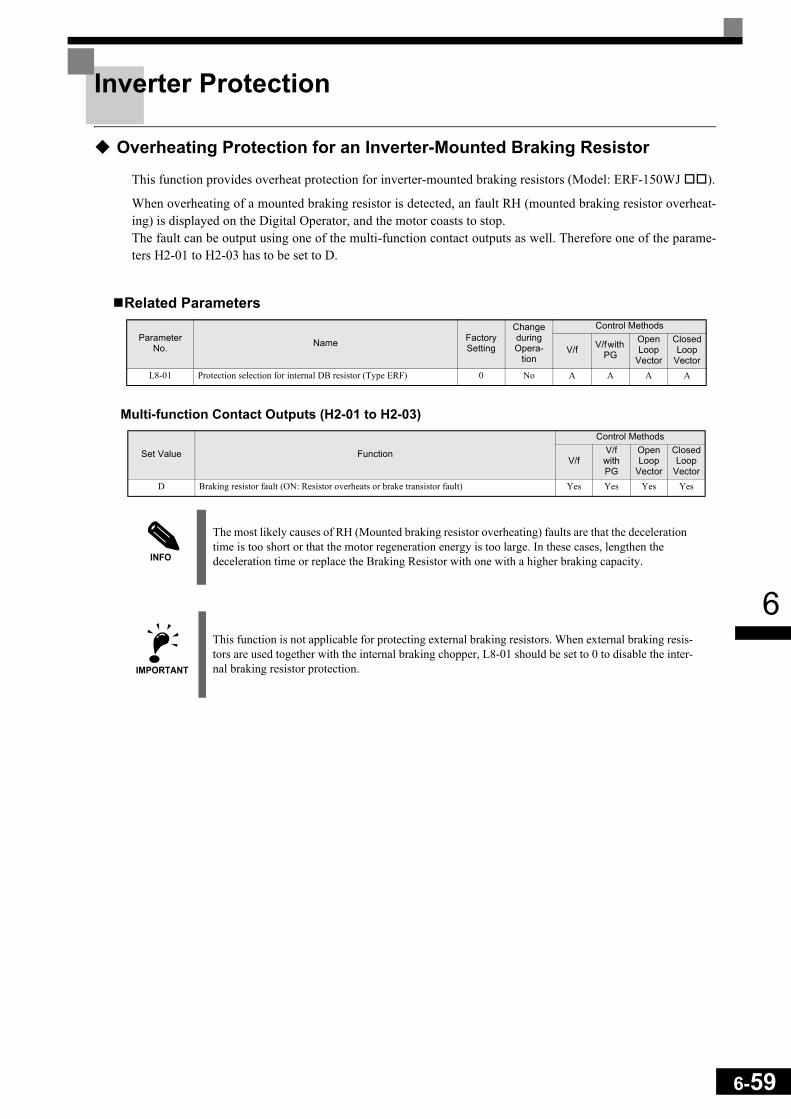
6
Inverter Protection
Overheating Protection for an Inverter-Mounted Braking Resistor
This function provides overheat protection for inverter-mounted braking resistors (Model: ERF-150WJ ).
When overheating of a mounted braking resistor is detected, an fault RH (mounted braking resistor overheat-ing) is displayed on the Digital Operator, and the motor coasts to stop. The fault can be output using one of the multi-function contact outputs as well. Therefore one of the parame-ters H2-01 to H2-03 has to be set to D.
Related Parameters
Multi-function Contact Outputs (H2-01 to H2-03)
Parameter No. Name Factory
Setting
Change during Opera-
tion
Control Methods
V/f V/f with PG
Open Loop
Vector
Closed Loop
VectorL8-01 Protection selection for internal DB resistor (Type ERF) 0 No A A A A
Set Value Function
Control Methods
V/fV/f with PG
Open Loop
Vector
Closed Loop
VectorD Braking resistor fault (ON: Resistor overheats or brake transistor fault) Yes Yes Yes Yes
INFO
The most likely causes of RH (Mounted braking resistor overheating) faults are that the deceleration time is too short or that the motor regeneration energy is too large. In these cases, lengthen the deceleration time or replace the Braking Resistor with one with a higher braking capacity.
IMPORTANT
This function is not applicable for protecting external braking resistors. When external braking resis-tors are used together with the internal braking chopper, L8-01 should be set to 0 to disable the inter-nal braking resistor protection.
6-59
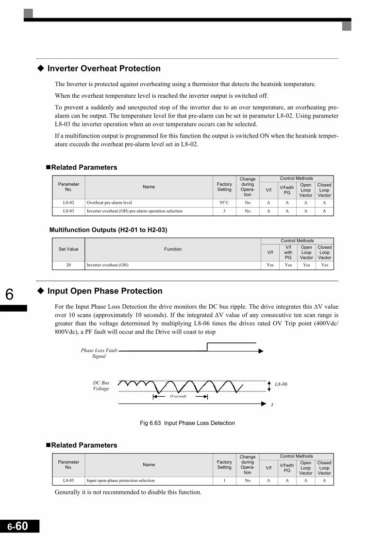
6-60
6
Inverter Overheat Protection
The Inverter is protected against overheating using a thermistor that detects the heatsink temperature.
When the overheat temperature level is reached the inverter output is switched off.
To prevent a suddenly and unexpected stop of the inverter due to an over temperature, an overheating pre-alarm can be output. The temperature level for that pre-alarm can be set in parameter L8-02. Using parameterL8-03 the inverter operation when an over temperature occurs can be selected.
If a multifunction output is programmed for this function the output is switched ON when the heatsink temper-ature exceeds the overheat pre-alarm level set in L8-02.
Related Parameters
Multifunction Outputs (H2-01 to H2-03)
Input Open Phase Protection
For the Input Phase Loss Detection the drive monitors the DC bus ripple. The drive integrates this ∆V valueover 10 scans (approximately 10 seconds). If the integrated ∆V value of any consecutive ten scan range isgreater than the voltage determined by multiplying L8-06 times the drives rated OV Trip point (400Vdc/800Vdc), a PF fault will occur and the Drive will coast to stop
Fig 6.63 Input Phase Loss Detection
Related Parameters
Generally it is not recommended to disable this function.
Parameter No. Name Factory
Setting
Change during Opera-
tion
Control Methods
V/f V/f with PG
Open Loop
Vector
Closed Loop
VectorL8-02 Overheat pre-alarm level 95°C No A A A A
L8-03 Inverter overheat (OH) pre-alarm operation selection 3 No A A A A
Set Value Function
Control Methods
V/fV/f with PG
Open Loop
Vector
Closed Loop
Vector20 Inverter overheat (OH) Yes Yes Yes Yes
Parameter No. Name Factory
Setting
Change during Opera-
tion
Control Methods
V/f V/f with PG
Open Loop
Vector
Closed Loop
VectorL8-05 Input open-phase protection selection 1 No A A A A
t
L8-06
Phase Loss FaultSignal
DC BusVoltage
10 seconds
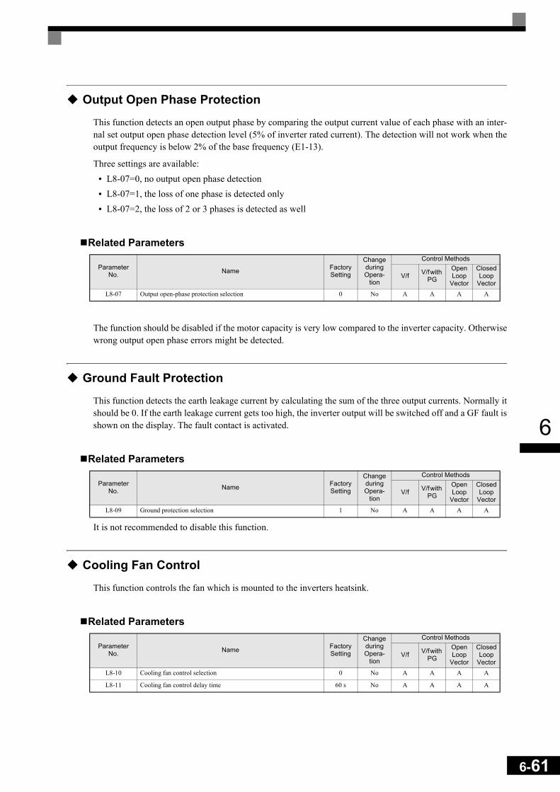
6
Output Open Phase Protection
This function detects an open output phase by comparing the output current value of each phase with an inter-nal set output open phase detection level (5% of inverter rated current). The detection will not work when theoutput frequency is below 2% of the base frequency (E1-13).
Three settings are available:• L8-07=0, no output open phase detection• L8-07=1, the loss of one phase is detected only• L8-07=2, the loss of 2 or 3 phases is detected as well
Related Parameters
The function should be disabled if the motor capacity is very low compared to the inverter capacity. Otherwisewrong output open phase errors might be detected.
Ground Fault Protection
This function detects the earth leakage current by calculating the sum of the three output currents. Normally itshould be 0. If the earth leakage current gets too high, the inverter output will be switched off and a GF fault isshown on the display. The fault contact is activated.
Related Parameters
It is not recommended to disable this function.
Cooling Fan Control
This function controls the fan which is mounted to the inverters heatsink.
Related Parameters
Parameter No. Name Factory
Setting
Change during Opera-
tion
Control Methods
V/f V/f with PG
Open Loop
Vector
Closed Loop
VectorL8-07 Output open-phase protection selection 0 No A A A A
Parameter No. Name Factory
Setting
Change during Opera-
tion
Control Methods
V/f V/f with PG
Open Loop
Vector
Closed Loop
VectorL8-09 Ground protection selection 1 No A A A A
Parameter No. Name Factory
Setting
Change during Opera-
tion
Control Methods
V/f V/f with PG
Open Loop
Vector
Closed Loop
VectorL8-10 Cooling fan control selection 0 No A A A A
L8-11 Cooling fan control delay time 60 s No A A A A
6-61

6-62
6
Selecting the Cooling Fan ControlUsing parameter L8-10 two modes can be selected:
0:The fan is ON only when the inverter output is ON, i.e. a voltage is output. This is the factory setting.
1:The fan is ON whenever the inverter power supply is switched ON.
If L8-10 is set to 0, the turn OFF delay time for the fan can be set in parameter L8-11. After a stop commandthe inverter waits for this time before switching OFF the cooling fan. The factory setting is 60 sec.
Setting the Ambient Temperature
At high ambient temperatures an output current derating has to be considered. The derating depends on theambient temperature and the protective structure of the inverter. The ambient temperature derating curve isshown in Fig 6.64. To ensure a safe inverter protection at high ambient temperatures, always set parameterL8-15 to the actual ambient temperature.
Fig 6.64 Ambient Temperature Derating Curve
Related Parameters
Parameter No. Name Factory
Setting
Change during Opera-
tion
Control Methods
V/f V/f with PG
Open Loop
Vector
Closed Loop
VectorL8-12 Ambient temperature 45 °C No A A A A
IMPORTANT
Since the inverter has no IP00/IP20 detection, at IP20 units the ambient temperature value in L8-12 has to be set 5° higher than the actual ambient temperature.
0
20
40
60
80
100
0 10 20 30 40 50 60
Temperature (°C)
Out
put C
urre
nt in
% o
f the
Rat
ed C
urre
nt
IP00IP20
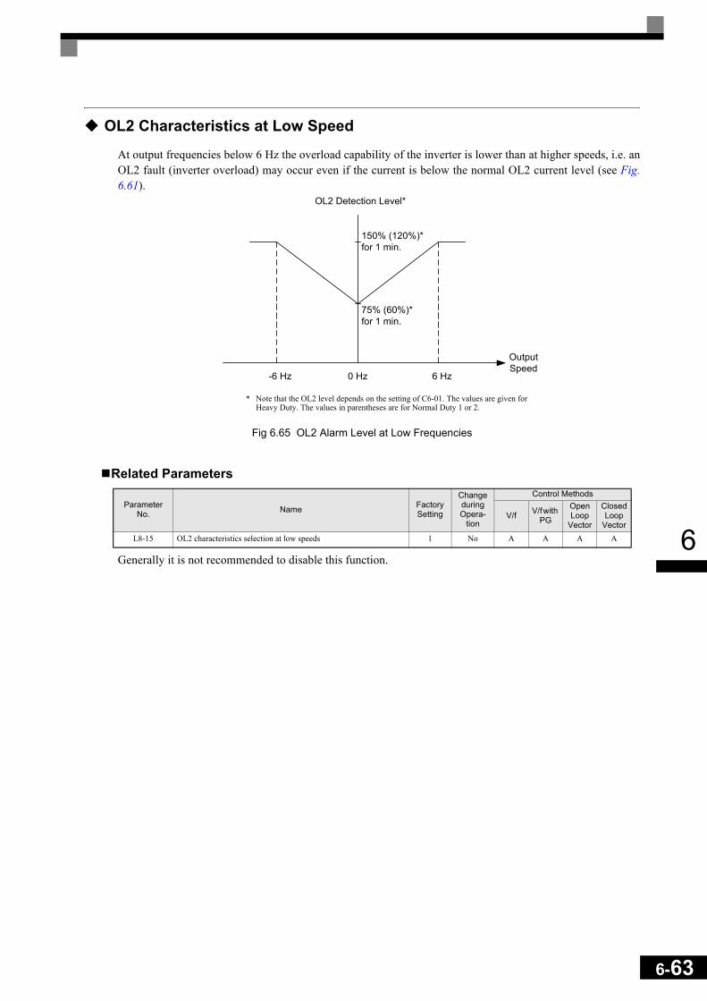
6
OL2 Characteristics at Low Speed
At output frequencies below 6 Hz the overload capability of the inverter is lower than at higher speeds, i.e. anOL2 fault (inverter overload) may occur even if the current is below the normal OL2 current level (see Fig.6.61).
Fig 6.65 OL2 Alarm Level at Low Frequencies
Related Parameters
Generally it is not recommended to disable this function.
Parameter No. Name Factory
Setting
Change during Opera-
tion
Control Methods
V/f V/f with PG
Open Loop
Vector
Closed Loop
VectorL8-15 OL2 characteristics selection at low speeds 1 No A A A A
OL2 Detection Level*
OutputSpeed
0 Hz
150% (120%)*for 1 min.
-6 Hz 6 Hz
75% (60%)*for 1 min.
* Note that the OL2 level depends on the setting of C6-01. The values are given for Heavy Duty. The values in parentheses are for Normal Duty 1 or 2.
6-63

6-64
6
Input Terminal Functions
Temporarily Switching Operation between Digital Operator and Control Circuit Terminals
The Inverter run command inputs and frequency reference inputs can be switched over between Local andRemote.
• Local:The digital operator is used as frequency reference and run command source.• Remote:The frequency reference and run command source can be set in the parameters b1-01 and b1-02.
If any input from H1-01 to H1-05 (digital input terminal S3 to S7 function selection) has been set to 1 (local/remote selection), this input can be used to switch over between local and remote.
Related Parameters
Multi-function Digital Inputs (H1-01 to H1-05)
Blocking the Inverter Output (Baseblock Commands)
Using a baseblock command the inverter output can be stopped immediately. In this case the motor will startcoasting. If the baseblock command is cleared, the inverter output operation is resumed. If speed search is enabled, the inverter detects the motor speed and the operation is resumed from the detectedspeed.If speed search is disabled, the operation is resumed from the frequency reference which was active before thebaseblock command.
To use the baseblock function one of the digital inputs must be set for baseblock, i.e. one of the parametersH1-01 to H1-05 (digital input terminal S3 to S7 function selection) must be set to 8 or 9 (Baseblock commandNO/NC).
Parameter No. Name Factory
Setting
Change during Opera-
tion
Control Methods
V/f V/f with PG
Open Loop
Vector
Closed Loop
Vectorb1-01 Reference selection 1 No Q Q Q Q
b1-02 RUN command source selection 1 No Q Q Q Q
Set Value Function
Control Methods
V/fV/f with PG
Open Loop
Vector
Closed Loop
Vector1 Local/Remote selection (ON: Operator, OFF: b1-01/02) Yes Yes Yes Yes
INFO
Local/Remote switching can also be performed using the LOCAL/REMOTE key on the Digital Oper-ator. When the Local/Remote function has been set for one external terminal, the LOCAL/REMOTE key function on the Digital Operator will be disabled.

6
Multi-function Digital Inputs (H1-01 to H1-05)
Timing ChartThe timing chart when using a baseblock command is shown in Fig 6.66.
Fig 6.66 Baseblock Commands
OH2 (Overheat) Alarm Signal Input
If a digital input is programmed for this function (H1- =B) an OH2 alarm message can be displayed on thedisplay by turning this input to ON. The fault contact will not be operated.
Multifunction Analog Input A2 Disable/Enable
If a digital input is programmed for this function (H1- =C) the analog input A2 can be enabled or disabledby switching the digital input ON/OFF (ON – Analog Input A2 enabled).
Set Value Function
Control Methods
V/fV/f
with PG
Open Loop
Vector
Closed Loop
Vector8 External baseblock NO (Normally Open contact: Baseblock when ON) Yes Yes Yes Yes
9 External baseblock NC (Normally Closed contact: Baseblock when OFF) Yes Yes Yes Yes
IMPORTANT
When a contactor between inverter and motor is used, always perform a base block command before opening the contactor.
Set Value Function
Control Methods
V/fV/f
with PG
Open Loop
Vector
Closed Loop
VectorB OH2 Alarm input (ON: OH2 is displayed) Yes Yes Yes Yes
Set Value Function
Control Methods
V/fV/f with PG
Open Loop
Vector
Closed Loop
VectorC Analog Input A2 enable/disable (ON: Enable) Yes Yes Yes Yes
Forward operation/Stop
Baseblock commandInput Cleared
Frequency reference
Output frequency
Coast to a stop
Speed search or operation with the previous frequency reference
6-65

6-66
6
Drive Enable/Disable
If a digital input is programmed for this function (H1- =6A) the drive can be enabled or disabled byswitching the digital input ON/OFF (ON – Drive enabled).
If the input is switched OFF while a RUN command is active the inverter will stop using the stopping methodset in b1-03.
Stopping Acceleration and Deceleration (Acceleration/Deceleration Ramp Hold)
• A multi-function input can be used to pause the acceleration or deceleration and maintain (hold) the outputfrequency. To program one digital input for this function one of the parameters H1-01 to H1-05 has to beset to 6A.
• The acceleration/deceleration is hold when the input is turned ON.• The acceleration/deceleration is restarted when the acceleration/deceleration ramp hold input is turned
OFF.• The motor will be stopped if a stop command is input while the acceleration/deceleration ramp hold input
is ON.• When parameter d4-01 (the frequency reference hold function selection) is set to 1, the held frequency will
be stored in memory. This stored frequency will be retained as frequency reference even after a power lossand the motor will be restarted at this frequency when a run command is input again.
Related Parameters
Multi-function Digital Inputs (H1-01 to H1-05)
Set Value Function
Control Methods
V/fV/f
with PG
Open Loop
Vector
Closed Loop
Vector6A Enable/Disable drive (ON: drive enabled) Yes Yes Yes Yes
Parameter No. Name Factory
Setting
Change during Opera-
tion
Control Methods
V/f V/f with PG
Open Loop
Vector
Closed Loop
Vectord4-01 Frequency reference hold function selection 0 No A A A A
Set Value Function
Control Methods
V/fV/f
with PG
Open Loop
Vector
Closed Loop
VectorA Acceleration/deceleration ramp hold (ON: hold is active) Yes Yes Yes Yes
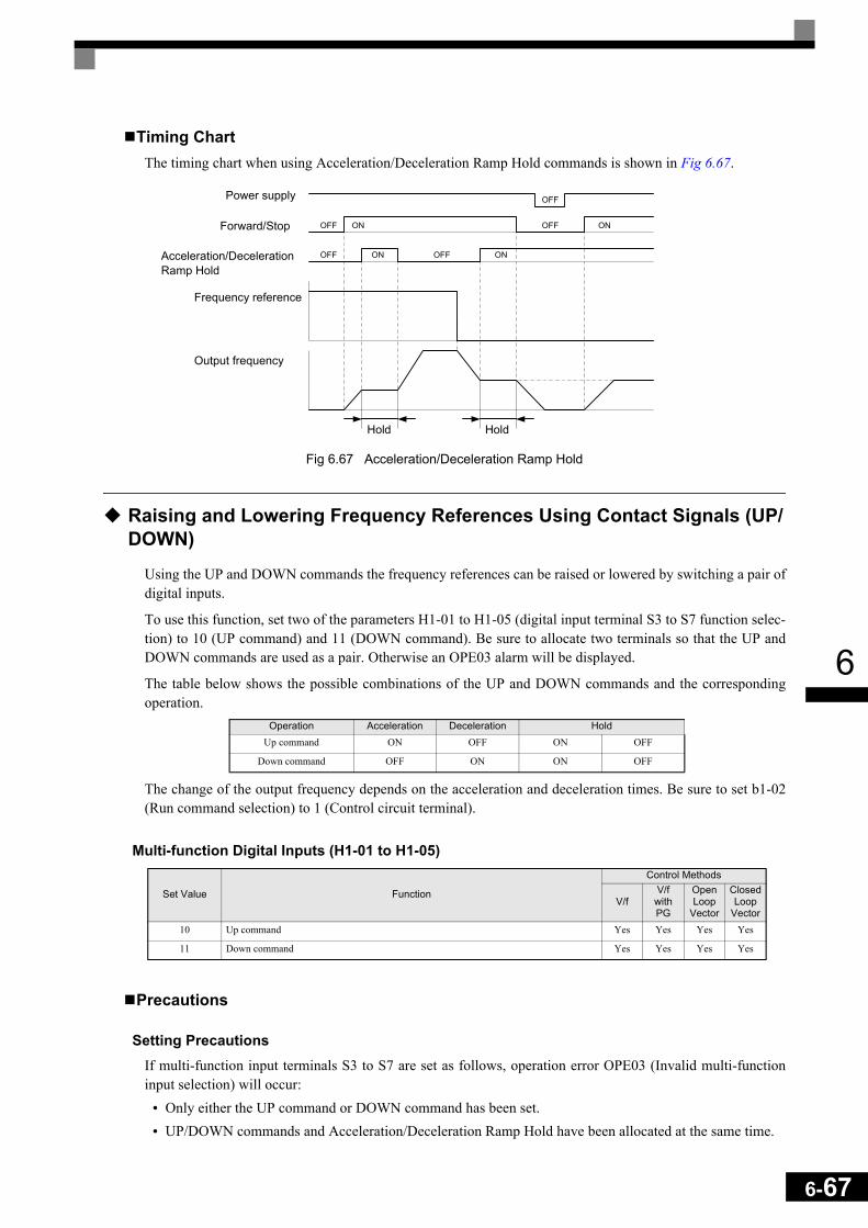
6
Timing ChartThe timing chart when using Acceleration/Deceleration Ramp Hold commands is shown in Fig 6.67.
Fig 6.67 Acceleration/Deceleration Ramp Hold
Raising and Lowering Frequency References Using Contact Signals (UP/DOWN)
Using the UP and DOWN commands the frequency references can be raised or lowered by switching a pair ofdigital inputs.
To use this function, set two of the parameters H1-01 to H1-05 (digital input terminal S3 to S7 function selec-tion) to 10 (UP command) and 11 (DOWN command). Be sure to allocate two terminals so that the UP andDOWN commands are used as a pair. Otherwise an OPE03 alarm will be displayed.
The table below shows the possible combinations of the UP and DOWN commands and the correspondingoperation.
The change of the output frequency depends on the acceleration and deceleration times. Be sure to set b1-02(Run command selection) to 1 (Control circuit terminal).
Multi-function Digital Inputs (H1-01 to H1-05)
Precautions
Setting PrecautionsIf multi-function input terminals S3 to S7 are set as follows, operation error OPE03 (Invalid multi-functioninput selection) will occur:
• Only either the UP command or DOWN command has been set.• UP/DOWN commands and Acceleration/Deceleration Ramp Hold have been allocated at the same time.
Operation Acceleration Deceleration HoldUp command ON OFF ON OFF
Down command OFF ON ON OFF
Set Value Function
Control Methods
V/fV/f
with PG
Open Loop
Vector
Closed Loop
Vector10 Up command Yes Yes Yes Yes
11 Down command Yes Yes Yes Yes
OFF
OFF ON OFF
OFF OFFON ON
ON
Power supply
Forward/Stop
Acceleration/DecelerationRamp Hold
Frequency reference
Output frequency
Hold Hold
6-67

6-68
6
Application Precautions• Frequency references which use the UP/DOWN commands are limited by the frequency reference upper
and lower limits set in parameters d2-01 to d2-03. In this case the value from the input A1 becomes the fre-quency reference lower limit. If using a combination of the frequency reference from terminal A1 and thefrequency reference lower limit set in either parameter d2-02 or d2-03, the larger limit value will becomethe frequency reference lower limit.
• If the UP/DOWN commands are used as frequency reference and the run command is input the inverteraccelerates to the frequency reference lower limit which is set in d2-02.
• When using UP/DOWN commands, multi-step operations are disabled.• When d4-01 (Frequency Reference Hold Function Selection) is set to 1, the frequency reference value
using the UP/DOWN functions is stored even after the power supply is turned OFF. When the power sup-ply is turned ON and the run command is input, the motor accelerates to the frequency reference that hasbeen stored. To reset (i.e., to 0 Hz) the stored frequency reference, turn ON the UP or DOWN commandwhile the run command is OFF.
Connection Example and Timing ChartThe time chart and settings example when the UP command is allocated to the digital input terminal S3, andthe DOWN command is allocated to terminal S4, are shown below.
Fig 6.68 Connection Example when UP/DOWN Commands Are Allocated
Parameter Name Set ValueH1-01 Multi-function input (terminal S3) 10
H1-02 Multi-function input (terminal S4) 11
Inverter
Forward operation/Stop
Reverse operation/Stop
Up command
Down command
Digital input neu-tral
Frequency reference lower limit0 to 10 V analog sig-
nal
S1
S2
S3
S4
SN
A1
AC

6
Fig 6.69 UP/DOWN Commands Timing Chart
Adding/Subtracting a Fixed Speed to an Analog Reference (Trim Control)
The trim control function adds or subtracts the value of parameter d4-02 to/from an analog frequency refer-ence.
To use this function, set two of the parameters H1-01 to H1-05 (multi-function contact terminal inputs S3 toS7 function selection) to 1C (Trim Control Increase command) and 1D (Trim Control Decrease command). Besure to allocate two terminals so that the Trim Control Increase command and Trim Control Decrease com-mand are used as a pair. Otherwise an OPE03 alarm will be displayed.
Related Parameters
Multi-function Digital Inputs (H1-01 to H1-05)
Parameter No. Name Factory
Setting
Change during Opera-
tion
Control Methods
V/f V/f with PG
Open Loop
Vector
Closed Loop
Vectord4-02 Trim control speed limits 10% No A A A A
Set Value Function
Control Methods
V/fV/f with PG
Open Loop
Vector
Closed Loop
Vector1C Trim control increase Yes Yes Yes Yes
1D Trim control decrease Yes Yes Yes Yes
Output frequencyUpper limit (d2-01)
Accelerates to lower limit Same
frequency
Lower limit (d2-02)
Forward operation/stop
UP command
DOWN command
Speed agree*
Reference frequency reset
Power supply
* The speed agree signal turns ON when the motor is not accelerating/decelerating while the run command is ON.
6-69

6-70
6
Trim Control Increase/Decrease Command and Frequency ReferenceThe frequency references using Trim Control Increase/Decrease command ON/OFF operations are shownbelow.
Application Precautions• Trim Control Increase/Decrease command is enabled when speed reference > 0 and the speed reference
source is an analog input (A1 or A2).• When the (analog frequency reference value - d4-02) < 0, the frequency reference is set to 0.• If only one of the Trim Control Increase command or Trim Control Decrease command has been set for a
digital input terminal, operation error OPE03 (invalid multi-function input selected) will occur.
Frequency ReferenceSet Frequency
Reference + d4-02
Set Frequency Reference
- d4-02HOLD
Trim Control Increase Command Terminal ON OFF ON OFF
Trim Control Decrease Com-mand Terminal OFF ON ON OFF
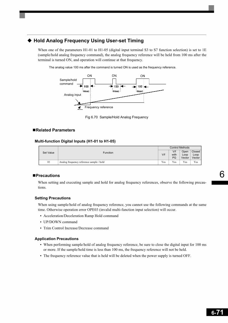
6
Hold Analog Frequency Using User-set Timing
When one of the parameters H1-01 to H1-05 (digital input terminal S3 to S7 function selection) is set to 1E(sample/hold analog frequency command), the analog frequency reference will be held from 100 ms after theterminal is turned ON, and operation will continue at that frequency.
Fig 6.70 Sample/Hold Analog Frequency
Related Parameters
Multi-function Digital Inputs (H1-01 to H1-05)
PrecautionsWhen setting and executing sample and hold for analog frequency references, observe the following precau-tions.
Setting PrecautionsWhen using sample/hold of analog frequency reference, you cannot use the following commands at the sametime. Otherwise operation error OPE03 (invalid multi-function input selection) will occur.
• Acceleration/Deceleration Ramp Hold command• UP/DOWN command• Trim Control Increase/Decrease command
Application Precautions• When performing sample/hold of analog frequency reference, be sure to close the digital input for 100 ms
or more. If the sample/hold time is less than 100 ms, the frequency reference will not be held.• The frequency reference value that is held will be deleted when the power supply is turned OFF.
Set Value Function
Control Methods
V/fV/f
with PG
Open Loop
Vector
Closed Loop
Vector1E Analog frequency reference sample / hold Yes Yes Yes Yes
Sample/holdcommand
Analog input
Frequency reference
The analog value 100 ms after the command is turned ON is used as the frequency reference.
6-71

6-72
6
Switching Operation Source to Communication Option Card
The source of frequency reference and RUN command can be switched between a Communication optioncard and the sources selected in b1-01 and b1-02. Set one of the parameters H1-01 to H1-05 (digital inputs S3to S7 function selection) to 2 to enable operation source switch over.
If a RUN command is active, the switch over will not be accepted.
Related Parameters
Multi-function Digital Inputs (H1-01 to H1-05)
Setting PrecautionsTo use the operation source switching function make the following settings:
• Set b1-01 (frequency reference source) to a value different from 3 (option card).• Set b1-02 (RUN command source) to a value different from 3 (option card).• Set one of the parameters H1-01 to H1-02 to 2.
Jog Frequency with Direction Commands (FJOG/RJOG)
The FJOG/RJOG function operates the inverter at the jog frequency. It can be activated by using the terminalON/OFF operation. When using the FJOG/RJOG commands, there is no need to input the RUN command.
To use this function, set one of the parameters H1-01 to H1-05 (digital input terminal S3 to S7 function selec-tion) to 12 (FJOG command) or 13 (RJOG command).
Related Parameters
Multi-Function Digital Inputs (H1-01 to H1-05)
Application Precautions• Jog frequencies using FJOG and RJOG commands have the priority over other frequency references.• When both FJOG command and RJOG commands are ON for 500 ms or longer at the same time, the
Inverter stops according to the setting in b1-03 (stopping method selection).
Set Value Function
Control Methods
V/fV/f
with PG
Open Loop
Vector
Closed Loop
Vector
2 Operation source selection: Option Card/ Inverter (ON: Inverter settings in b1-01 and b1-02, OFF: Option Card) Yes Yes Yes Yes
Parameter No. Name Factory
Setting
Change during Opera-
tion
Control Methods
V/f V/f with PG
Open Loop
Vector
Closed Loop
Vectord1-17 Jog frequency reference 6.00 Hz Yes Q Q Q Q
Set Value Function
Control Methods
V/fV/f with PG
Open Loop
Vector
Closed Loop
Vector12 FJOG command (ON: Forward run at jog frequency d1-17) Yes Yes Yes Yes
13 RJOG command (ON: Reverse run at jog frequency d1-17) Yes Yes Yes Yes

6
Stopping the Inverter on External Device Errors (External Error Function)
The external error function activates the error contact output and stops the Inverter operation. Using this func-tion the inverter operation can be stopped on peripheral devices break down or other errors. The digital opera-tor will display EFx (External error [input terminal Sx]). The x in EFx shows the number of the terminal atwhich the external error signal is input. For example, if an external error signal is input to terminal S3, EF3will be displayed.
To use the external error function, set one of the values 20 to 2F in one of the parameters H1-01 to H1-05 (dig-ital input terminal S3 to S7 function selection).
Select the value to be set in H1-01 to H1-05 from a combination of any of the following three conditions.• Signal input level from peripheral devices• External error detection method• Operation after external error detection
The following table shows the relationship between the combinations of conditions and the set value in H1-.
* 1. Sets the input level at which errors are detected. (NO contact: External error when ON; NC contact: External error when OFF).* 2. Set the detection method to detect errors using either constant detection or detection during operation.
Constant detection: Detects while power is supplied to the Inverter.Detection during operation: Detects only during Inverter operation.
Set Value
Input Level (See Note *1)
Error Detection Method (See Note *2) Operation During Error Detection
NO Contact NC Contact Constant Detection
Detection During
Operation
Decelerate to Stop (Error)
Coast to Stop (Error)
Emergency Stop (Error)
Continue Operation (Warning)
20 Yes Yes Yes
21 Yes Yes Yes
22 Yes Yes Yes
23 Yes Yes Yes
24 Yes Yes Yes
25 Yes Yes Yes
26 Yes Yes Yes
27 Yes Yes Yes
28 Yes Yes Yes
29 Yes Yes Yes
2A Yes Yes Yes
2B Yes Yes Yes
2C Yes Yes Yes
2D Yes Yes Yes
2E Yes Yes Yes
2F Yes Yes Yes
6-73

6-74
6
Output Terminal Functions
The digital multifunction outputs can be set for several functions using the H2-01 to H2-03 parameters (termi-nal M1 to M6 function selection). These functions are described in the following section.
Related Parameters
During Run (Setting: 0) and During Run 2 (Setting: 37)
During Run (Setting: 0)
During Run 2 (Setting: 37)
These outputs can be used to indicate the inverter’s operating status.
Fig 6.71 Timing Chart for “During RUN” Output
Zero Speed (Setting: 1)
Fig 6.72 Timing Chart for Zero-speed
Parameter No. Name Factory
Setting
Change during Opera-
tion
Control Methods
V/f V/f with PG
Open Loop
Vector
Closed Loop
VectorH2-01 Terminal M1-M2 function selection 0 No A A A A
H2-02 Terminal M3-M4 function selection 1 No A A A A
H2-03 Terminal M5-M6 function selection 2 No A A A A
OFF The Run command is OFF and there is not output voltage.
ON The Run command is ON or a voltage is being output.
OFF The inverter is not outputting a frequency. (Baseblock, DC injection braking or stopped)
ON The inverter is outputting a frequency.
OFF The output frequency is higher than the zero speed level (b2-01).
ON The output frequency is lower than the zero speed level (b2-01).
OFF ON
OFF
OFF
OFF
ON
ON
ON
Run command
Baseblock command
Output frequency
During run 1 output
During run 2 output
Zero speed level (b2-01)
OFF ONZero-speed output
Output frequency

6
Inverter Operation Ready (Setting: 6)If a multifunction output is programmed for this function the output will be switched ON when the initialisa-tion of the inverter at startup has finished without any faults.
During DC Bus Undervoltage (Setting: 7)If a multifunction output is programmed for this function the output is switched ON as long as a DC bus und-ervoltage is detected.
During Baseblock (Setting: 8)If a multifunction output is programmed for this function the output is switched ON as long as the inverter out-put is base blocked.
Frequency Reference Source Selection (Setting: 9)If a multifunction output is programmed for this function the output is ON when the digital operator is selectedas frequency reference source. If any other frequency reference is selected the output is switched OFF.
Run Command Selection Status (Setting: A)If a multifunction output is programmed for this function the output is switched ON when the digital operatoris selected as RUN command source. If any other RUN command source is selected output is switched OFF.
Fault Output (Setting: E)If a multifunction output is programmed for this function the output is switched ON when any fault differentfrom CPF00 and CPF01 occurs. The output is also not switched at minor faults. (Refer to page 7-2 pp. for afault list.)
Minor Fault Output (Setting: 10)If a multifunction output is programmed for this function the output is switched ON when a minor fault occurs(refer to page 7-9 pp. for an alarm list).
Fault Reset Command Active (Setting: 11)If a multifunction output is set for this function the output is switched ON as long as a fault reset command isinput at one of the digital inputs.
During Reverse Run (Setting: 1A)If a multifunction output is programmed for this function the output is switched ON whenever a RUN com-mand in reverse direction is active. The contact will also be ON during DC injection, Braking and Base Block.It will not work when a forward RUN command is input.
During Base Block 2 (Setting: 1B)If a multifunction output is programmed for this function the output is switched OFF as long as a Baseblockcommand is input at a multifunction input.
6-75

6-76
6
Motor 2 Selection (Setting: 1C)If a multifunction output is programmed for this function the output is switched ON when motor 2 is selected.
During Regenerative Operation (Setting: 1D)If a multifunction output is programmed for this function the output is switched ON when the motor worksregenerative, i.e. when energy is fed back to the inverter.
During Run 2 (Setting: 37)When a multifunction output is set to this function the output is switched ON when a frequency is output. Itwill be switched OFF during Baseblock, DC injection braking or Stop.
Drive Enabled (Setting: 38)If a multifunction output is programmed for this function the output is switched ON when the drive is enabled.The drive can be enabled or disabled using a digital multifunction input.

6
Monitor Parameters
Using the Analog Monitor Outputs
This section explains the usage of the internal analog monitor outputs.
Related Parameters
Selecting Analog Monitor ItemsSome of the digital operator monitor items (U1- [status monitor]) can be output at the multi-function ana-log output terminals FM-AC and AM-AC. Refer to page 5-64, Status Monitor Parameters: U1 and set theparameter number of U1 group ( part of U1- ) for the parameters H4-01 or H4-04.
Adjusting the Analog Monitor ItemsAdjust the output current/voltage for multi-function analog output terminals FM-AC and AM-AC using thegain and bias in H4-02, H4-03, H4-05, and H4-06.
The gain sets the analog output voltage/current value which is equal to 100% of the monitor item.The bias sets the analog output voltage/current value which is equal to 0% of the monitor item.Note that the maximum output voltage/current is 10V/20mA. A voltage/current higher than these values cannot be output.
Parameter No. Name Factory
Setting
Change during Opera-
tion
Control Methods
V/f V/f with PG
Open Loop
Vector
Closed Loop
VectorH4-01 Monitor selection (terminal FM) 2 No A A A A
H4-02 Gain (terminal FM) 100% Yes Q Q Q Q
H4-03 Bias (terminal FM) 0.0% Yes A A A A
H4-04 Monitor selection (terminal AM) 3 No A A A A
H4-05 Gain (terminal AM) 50% Yes Q Q Q Q
H4-06 Bias (terminal AM) 0.0% Yes A A A A
H4-07 Analog output 1 signal level selection (FM) 0 No A A A A
H4-08 Analog output signal 2 level selection (AM) 0 No A A A A
6-77

6-78
6
Adjustment ExamplesThe influence of the settings of gain and bias on the analog output channel is shown on three examples in Fig 6.69.
Fig 6.73 Monitor Output Adjustment
Switching Analog Monitor Signal LevelsThe values of some monitor items can be both, positive or negative. If these items shall be output at an analogoutput, the signal level should be set to –10V to +10V (H4-07/08 = 1). Negative values will be output as neg-ative voltage (–10V to 0) and positive values will be output as positive voltage (0 to +10V).For monitor items that can have positive or negative values please refer to page 5-64, Status Monitor Parame-ters: U1.
Both analog outputs can create a 4-20 mA current signal as well. Therefore the parameters H4-07 and H4-08have to be set to 2. Additionally the jumper CN15 has to be set to current output for each channel. Refer topage 2-23, Jumper CN15 and DIP Switch S1 for details about the jumper setting.
Using the Pulse Train Monitor Output
Related Parameters
Selecting Pulse Monitor ItemsSome of the digital operator monitor items (U1- [status monitor]) can be output at pulse monitor terminalMP-AC. Refer to page 5-64, Status Monitor Parameters: U1 and set the part of U1- (Status monitor)for H6-06.
Adjusting the Pulse Monitor ItemsTo adjust the pulse frequency output scaling, set the pulse output frequency which is equal to 100% of themonitor item in parameter H6-07.
Set H6-06 to 2, and H6-07 to 0, to output the frequency synchronous with the Inverter's U-phase output fre-quency.
Parameter No. Name Factory
Setting
Change during Opera-
tion
Control Methods
V/f V/f with PG
Open Loop
Vector
Closed Loop
VectorH6-06 Pulse train monitor selection 2 Yes A A A A
H6-07 Pulse train monitor scaling 1440 Hz Yes A A A A
0V
10V
100%
Gain: 100%Bias: 0%
Gain: 170%Bias: 30%
Gain: 0%Bias: 100%
Monitor item(e.g. Output Frequency)
Output voltage/current
3V/8.8mA

6
Application PrecautionsWhen using the pulse monitor output, connect a peripheral device according to the following load conditions.If the load conditions are different, there is a risk of characteristic insufficiency or damage to the inverter.
Output Voltage (Isolated)VRL (V) Load Impedance
+5 V min. 1.5 kΩ min.+8 V min. 3.5 kΩ min.
+10 V min. 10 kΩ min.
Load Impedance
External Power Supply (V)
12 VDC±10%,15 VDC±10%
Max. Current 16 mA
External power supply
Sinking current
Load impedance
6-79

6-80
6
Individual Functions
Using MEMOBUS Communications
Serial communications with a Programmable Logic Controls (PLCs) or similar devices can be performedusing the MEMOBUS protocol.
MEMOBUS Communications ConfigurationMEMOBUS communications are configured using 1 master (PLC) and a maximum of 31 slaves. Serial com-munications between master and slave are normally started by the master and the slaves respond.
The master performs serial communications with only one slave at a time. Consequently, you must set theaddress of each slave before, so that the master can perform serial communications using that address. A slavethat receives a command from the master performs the specified function and sends a response to the master.
Fig 6.74 Example of Connections between PLC and Inverter
Communications SpecificationsThe MEMOBUS communications specifications are shown in the following table.
Item Specifications
Interface RS-422, RS-485
Communications Cycle Asynchronous (Start-stop synchronization)
Communications Parameters
Baud rate: Select from 1,200, 2,400, 4,800, 9,600 and 19,200 bps.
Data length: 8 bits fixed
Parity: Select from even, odd, or none.
Stop bits: 1 bit fixed
Communications Protocol MEMOBUS
Number of Connectable Units 31 units max.
PLC
Inverter Inverter Inverter
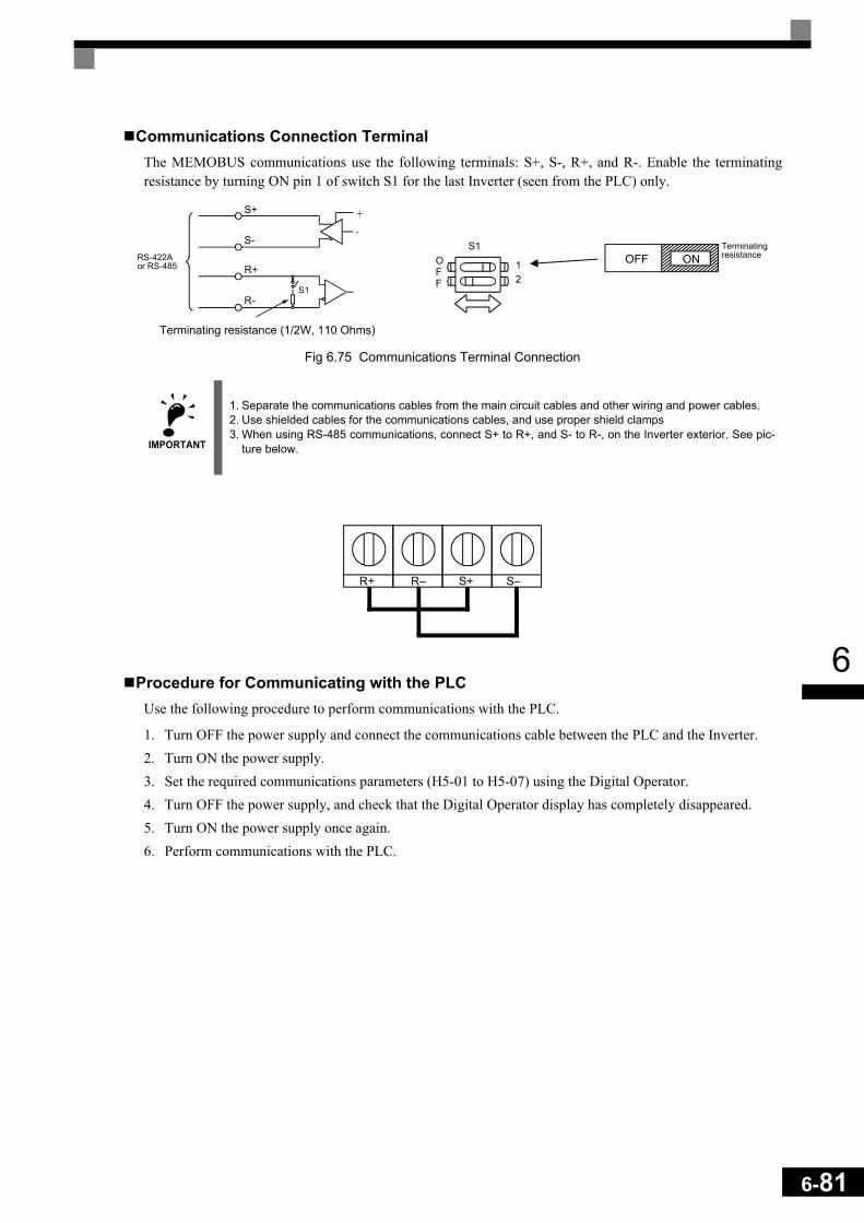
6
Communications Connection TerminalThe MEMOBUS communications use the following terminals: S+, S-, R+, and R-. Enable the terminatingresistance by turning ON pin 1 of switch S1 for the last Inverter (seen from the PLC) only.
Fig 6.75 Communications Terminal Connection
Procedure for Communicating with the PLCUse the following procedure to perform communications with the PLC.
1. Turn OFF the power supply and connect the communications cable between the PLC and the Inverter.2. Turn ON the power supply.3. Set the required communications parameters (H5-01 to H5-07) using the Digital Operator.4. Turn OFF the power supply, and check that the Digital Operator display has completely disappeared.5. Turn ON the power supply once again.6. Perform communications with the PLC.
IMPORTANT
1. Separate the communications cables from the main circuit cables and other wiring and power cables.2. Use shielded cables for the communications cables, and use proper shield clamps3. When using RS-485 communications, connect S+ to R+, and S- to R-, on the Inverter exterior. See pic-
ture below.
Terminating resistance (1/2W, 110 Ohms)
RS-422Aor RS-485
S1
S1OFF
12
Terminating resistance
6-81
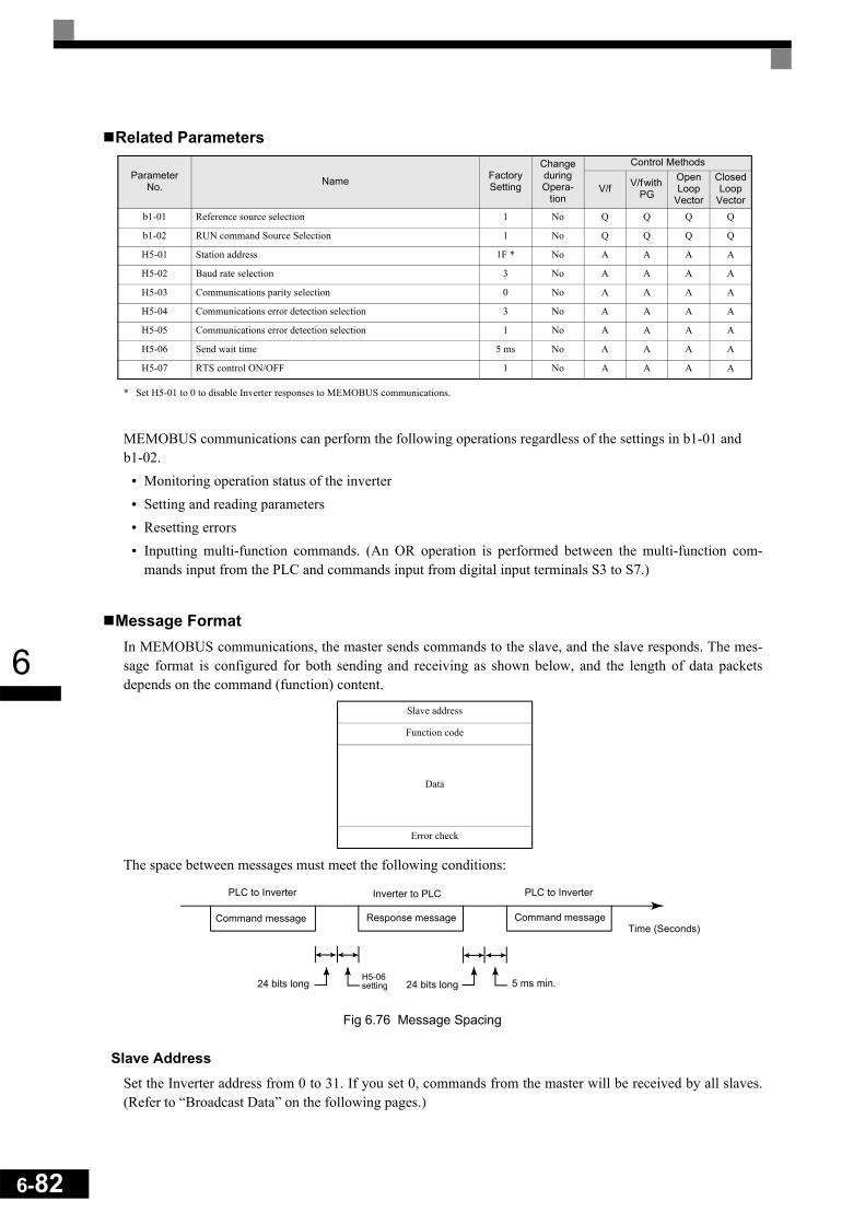
6-82
6
Related Parameters
* Set H5-01 to 0 to disable Inverter responses to MEMOBUS communications.
MEMOBUS communications can perform the following operations regardless of the settings in b1-01 and b1-02.
• Monitoring operation status of the inverter• Setting and reading parameters• Resetting errors• Inputting multi-function commands. (An OR operation is performed between the multi-function com-
mands input from the PLC and commands input from digital input terminals S3 to S7.)
Message FormatIn MEMOBUS communications, the master sends commands to the slave, and the slave responds. The mes-sage format is configured for both sending and receiving as shown below, and the length of data packetsdepends on the command (function) content.
The space between messages must meet the following conditions:
Fig 6.76 Message Spacing
Slave AddressSet the Inverter address from 0 to 31. If you set 0, commands from the master will be received by all slaves.(Refer to “Broadcast Data” on the following pages.)
Parameter No. Name Factory
Setting
Change during Opera-
tion
Control Methods
V/f V/f with PG
Open Loop
Vector
Closed Loop
Vectorb1-01 Reference source selection 1 No Q Q Q Q
b1-02 RUN command Source Selection 1 No Q Q Q Q
H5-01 Station address 1F * No A A A A
H5-02 Baud rate selection 3 No A A A A
H5-03 Communications parity selection 0 No A A A A
H5-04 Communications error detection selection 3 No A A A A
H5-05 Communications error detection selection 1 No A A A A
H5-06 Send wait time 5 ms No A A A A
H5-07 RTS control ON/OFF 1 No A A A A
Slave address
Function code
Data
Error check
PLC to InverterInverter to PLCPLC to Inverter
Command message Response message Command messageTime (Seconds)
24 bits long 5 ms min.H5-06setting24 bits long
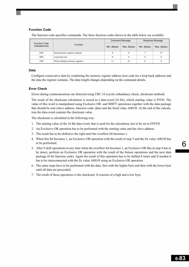
6
Function CodeThe function code specifies commands. The three function codes shown in the table below are available.
DataConfigure consecutive data by combining the memory register address (test code for a loop back address) andthe data the register contains. The data length changes depending on the command details.
Error CheckErrors during communications are detected using CRC-16 (cyclic redundancy check, checksum method).
The result of the checksum calculation is stored in a data-word (16 bit), which starting value is FFFH. Thevalue of this word is manipulated using Exclusive OR- and SHIFT operations together with the data packagethat should be sent (slave address, function code, data) and the fixed value A001H. At the end of the calcula-tion the data-word contains the checksum value.
The checksum is calculated in the following way:
1. The starting value of the 16 Bit data-word, that is used for the calculation, has to be set to FFFFH.2. An Exclusive OR operation has to be performed with the starting value and the slave address.3. The result has to be shifted to the right until the overflow bit becomes 1.4. When this bit becomes 1, an Exclusive OR operation with the result of step 3 and the fix value A001H has
to be performed.5. After 8 shift operations (every time when the overflow bit becomes 1, an Exclusive OR like in step 4 has to
be done), perform an Exclusive OR operation with the result of the former operations and the next datapackage (8 bit function code). Again the result of this operation has to be shifted 8 times and if needed ithas to be interconnected with the fix value A001H using an Exclusive OR operation.
6. The same steps have to be performed with the data, first with the higher byte and then with the lower byteuntil all data are proceeded.
7. The result of these operations is the checksum. It consists of a high and a low byte.
Function Code (Hexadecimal) Function
Command Message Response Message
Min. (Bytes) Max. (Bytes) Min. (Bytes) Max. (Bytes)
03H Read memory register contents 8 8 7 37
08H Loop back test 8 8 8 8
10H Write multiple memory registers 11 41 8 8
6-83
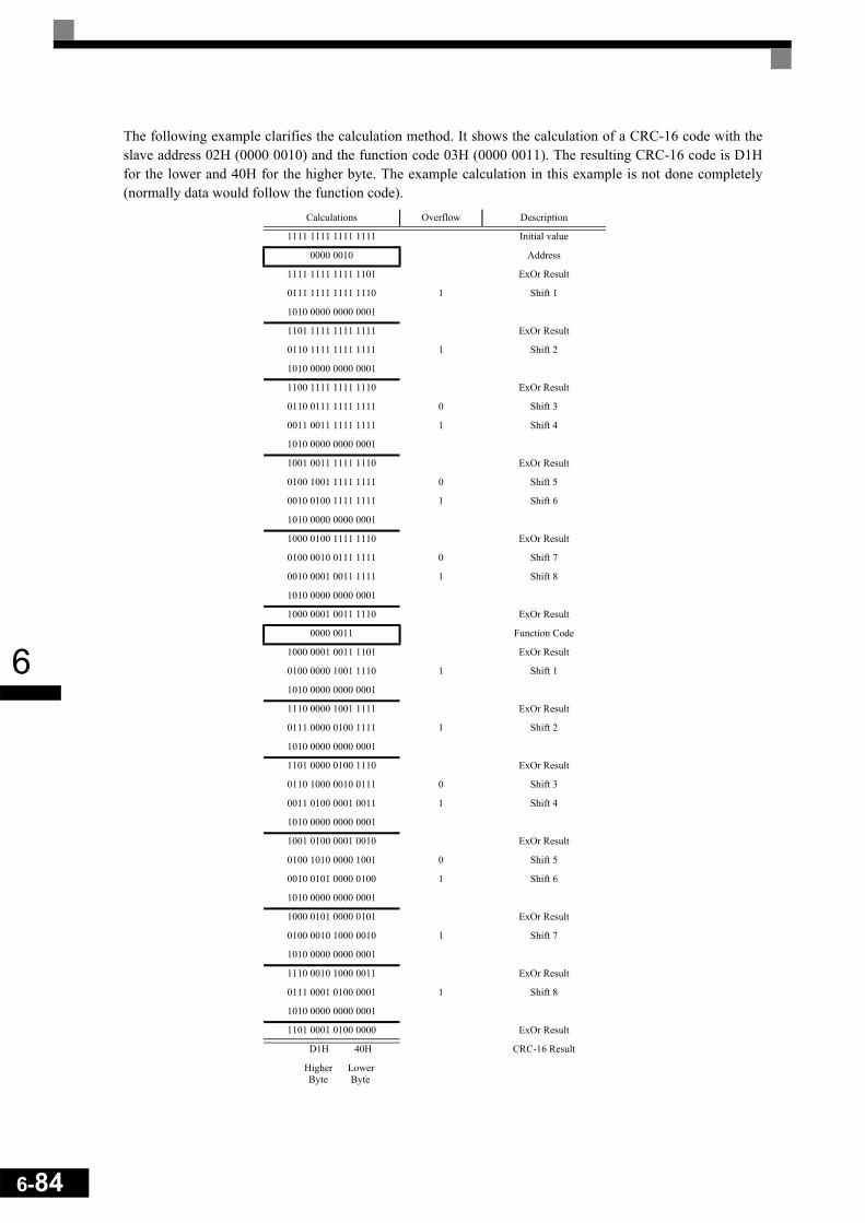
6-84
6
The following example clarifies the calculation method. It shows the calculation of a CRC-16 code with theslave address 02H (0000 0010) and the function code 03H (0000 0011). The resulting CRC-16 code is D1Hfor the lower and 40H for the higher byte. The example calculation in this example is not done completely(normally data would follow the function code).
Calculations Overflow Description
1111 1111 1111 1111 Initial value
0000 0010 Address
1111 1111 1111 1101 ExOr Result
0111 1111 1111 1110 1 Shift 1
1010 0000 0000 0001
1101 1111 1111 1111 ExOr Result
0110 1111 1111 1111 1 Shift 2
1010 0000 0000 0001
1100 1111 1111 1110 ExOr Result
0110 0111 1111 1111 0 Shift 3
0011 0011 1111 1111 1 Shift 4
1010 0000 0000 0001
1001 0011 1111 1110 ExOr Result
0100 1001 1111 1111 0 Shift 5
0010 0100 1111 1111 1 Shift 6
1010 0000 0000 0001
1000 0100 1111 1110 ExOr Result
0100 0010 0111 1111 0 Shift 7
0010 0001 0011 1111 1 Shift 8
1010 0000 0000 0001
1000 0001 0011 1110 ExOr Result
0000 0011 Function Code
1000 0001 0011 1101 ExOr Result
0100 0000 1001 1110 1 Shift 1
1010 0000 0000 0001
1110 0000 1001 1111 ExOr Result
0111 0000 0100 1111 1 Shift 2
1010 0000 0000 0001
1101 0000 0100 1110 ExOr Result
0110 1000 0010 0111 0 Shift 3
0011 0100 0001 0011 1 Shift 4
1010 0000 0000 0001
1001 0100 0001 0010 ExOr Result
0100 1010 0000 1001 0 Shift 5
0010 0101 0000 0100 1 Shift 6
1010 0000 0000 0001
1000 0101 0000 0101 ExOr Result
0100 0010 1000 0010 1 Shift 7
1010 0000 0000 0001
1110 0010 1000 0011 ExOr Result
0111 0001 0100 0001 1 Shift 8
1010 0000 0000 0001
1101 0001 0100 0000 ExOr Result
D1H 40H CRC-16 Result
Higher Lower Byte Byte

6
MEMOBUS Message ExampleAn example of MEMOBUS command/response messages is given below.
Reading Inverter Memory Register ContentsThe content of maximum 16 inverter memory registers can be readout at a time.
Among other things the command message must contain the start address of the first register that is to be readout and the quantity of registers that should be read out. The response message will contain the content of thefirst and the consecutive number of registers that has been set for the quantity.
The contents of the memory register are separated into higher 8 bits and lower 8 bits.
The following tables show message examples when reading status signals, error details, data link status, andfrequency references from the slave 2 Inverter.
Loop back TestThe loop back test returns command messages directly as response messages without changing the contents tocheck the communications between the master and slave. You can set user-defined test code and data values.
The following table shows a message example when performing a loop back test with the slave no. 1.
Command Message Response Message (During Normal Operation)
Response Message (During Error)
Slave Address 02H Slave Address 02H Slave Address 02H
Function Code 03H Function Code 03H Function Code 83H
Start AddressHigher 00H Data quantity 08H Error code 03H
Lower 20H 1st storage register
Higher 00HCRC-16
Higher F1H
QuantityHigher 00H Lower 65H Lower 31H
Lower 04H Next storage register
Higher 00H
CRC-16Higher 45H Lower 00H
Lower F0H Next storage register
Higher 00H
Lower 00H
Next storage register
Higher 01H
Lower F4H
CRC-16Higher AFH
Lower 82H
Command Message Response Message (During Normal Operation)
Response Message (During Error)
Slave address 01H Slave address 01H Slave address 01H
Function code 08H Function code 08H Function code 89H
Test CodeHigher 00H
Test CodeHigher 00H Error Code 01H
Lower 00H Lower 00HCRC-16
Higher 86H
DataHigher A5H
DataHigher A5H Lower 50H
Lower 37H Lower 37H
CRC-16Higher DAH
CRC-16Higher DAH
Lower 8DH Lower 8DH
6-85

6-86
6
Writing to Multiple Inverter Memory RegistersThe writing of inverter memory registers works similar to the reading process, i.e. the address of the first reg-ister that is to be written and the quantity of to be written registers must be set in the command message.
The to be written data must be consecutive, starting from the specified address in the command message. Thedata order must be higher 8 bits, then lower 8 bits. The data must be in memory register address order.
The following table shows an example of a message where a forward operation has been set with a frequencyreference of 60.0 Hz for the inverter with the slave address 01H.
Command Message Response Message (During Normal Operation)
Response Message (During Error)
Slave Address 01H Slave Address 01H Slave Address 01H
Function Code 10H Function Code 10H Function Code 90H
Start AddressHigher 00H
Start AddressHigher 00H Error code 02H
Lower 01H Lower 01HCRC-16
Higher CDH
QuantityHigher 00H
QuantityHigher 00H Lower C1H
Lower 02H Lower 02H
No. of data 04HCRC-16
Higher 10H
Lead dataHigher 00H Lower 08H
Lower 01H
Next dataHigher 02H
Lower 58H * No. of data = 2 x (quantity)
CRC-16Higher 63H
Lower 39H
IMPORTANT
For the number of data value in the command message the double value of the data quantity must be taken.

6
Data TablesThe data tables are shown below. The types of data are as follows: Reference data, monitor data, and broadcastdata.
Reference DataThe reference data table is shown below. These data can be read and written. They cannot be used for monitor-ing functions.
Note:Write 0 to all unused bits. Also, do not write data to reserved registers.
Register Address Contents0000H Reserved
0001H
Run operation and input commands
Bit 0 Forward run
Bit 1 Reverse run
Bit 2 External error
Bit 3 Reset command
Bit 4 ComNet
Bit 5 ComCtrl
Bit 6 Multi-function input command 3
Bit 7 Multi-function input command 4
Bit 8 Multi-function input command 5
Bit 9 Multi-function input command 6
Bit A Multi-function input command 7
Bits B to F Not used
0002H Frequency reference (Set units using parameter o1-03)
0003H to 0005H Not used
0006H PID target value
0007H Analog output 1 setting (-11 V/-726 to 11 V/726) → 10V = 660
0008H Analog output 2 setting (-11 V/-726 to 11 V/726) → 10V = 660
0009H
Multi-function contact output setting
Bit 0 Contact output 1 (Terminal M1-M2) 1: ON 0: OFF
Bit 1 Contact output 2 (Terminal M3-M4) 1: ON 0: OFF
Bit 2 Contact output 3 (Terminal M5-M6) 1: ON 0: OFF
Bits 3 to 5 Not used
Bit 6 Enables/Disables error contact (terminal MA-MC) setting using bit 7 1: ON 0: OFF
Bit 7 Error contact (terminal MA-MC) 1: ON 0: OFF
Bits 8 to F Not used
000AH to 000EH Not used
000FH
Reference selection settings
Bit 0 Not used
Bit 1 Input PID target value 1: Enabled 0: Disabled
Bits 3 to B Not used
C Broadcast data terminal S5 input 1: Enabled 0: Disabled
D Broadcast data terminal S6 input 1: Enabled 0: Disabled
E Broadcast data terminal S7 input 1: Enabled 0: Disabled
F Not used
6-87

6-88
6
Monitor DataThe following table shows the monitor data. Monitor data can only be read.Register Address. Contents
0010H
Inverter status signal
Bit 0 During run
Bit 1 Zero speed
Bit 2 During reverse operation
Bit 3 Reset signal active
Bit 4 During speed agree
Bit 5 Inverter ready
Bit 6 Minor fault
Bit 7 Major fault
Bits 8 to F Not used
0011H
Operator status
Bit 0 During OPE alarm
Bit 1 During fault
Bit 2 Operator in programming mode
Bit 3, 4 00: JVOP-160 attached, 01: JVOP-161 attached, 11: PC connected
Bit 5 to F Not used
0012H OPE Fault Number
0013H Not used
0014H
Fault Content 1
Bit 0 PUF, DC bus fuse blown
Bit 1 UV1
Bit 2 UV2
Bit 3 UV3
Bit 4 Not used
Bit 5 GF, Ground fault
Bit 6 OC, Over current
Bit 7 OV, DC bus over voltage
Bit 8 OH, Inverter heatsink overheat pre-alarm
Bit 9 OH1, Inverter heatsink overheat
Bit A OL1, Motor overload
Bit B OL2, Inverter overload
Bit C OL3, Overtorque detection 1
Bit D OL4, Overtorque detection 2
Bit E RR, Internal braking transistor fault
Bit F RH, Inverter mounted braking resistor overheat
0015H
Fault Content 2
Bit 0 EF3, External fault set on terminal S3
Bit 1 EF4, External fault set on terminal S4
Bit 2 EF5, External fault set on terminal S5
Bit 3 EF6, External fault set on terminal S6
Bit 4 EF7, External fault set on terminal S7
Bit 5 Not used
Bit 6 Not used
Bit 7 OS, Overspeed detected
Bit 8 DEV, Speed deviation detected
Bit 9 PGO, PG disconnected
Bit A PF, Input phase loss
Bit B LF, Output open phase
Bit C OH3, Motor overheat pre-alarm (PTC analog input)
Bit D OPR, Digital operator disconnected

6
0015HBit E ERR,
Bit F OH4, Motor overheat (PTC analog input)
0016H
Fault Content 3
Bit 0 CE, Memobus communications error
Bit 1 BUS, Bus option communications error
Bit 2/3 Not used
Bit 4 CF, Control fault
Bit 5 Not used
Bit 6 EF0, External fault from optional input card
Bit 7 FBL, PID feedback loss
Bit 8 UL3, Undertorque detection 1
Bit 9 UL4, Undertorque detection 2
Bit A OL7, High Slip Braking overload
Bit B to F Not used
0017H
CPF Fault Content 1
Bit 0/1 Not used
Bit 2 CPF02
Bit 3 CPF03
Bit 4 Not used
Bit 5 CPF05
Bit 6 CPF06
Bit 7 to F Not used
0018H
CPF Fault Content 2
Bit 0 CPF20
Bit 1 CPF21
Bit 2 CPF22
Bit 3 CPF23
Bit 4 to F Not used
0019H
Alarm Content 1
Bit 0 UV, DC bus undervoltage
Bit 1 OV, DC bus overvoltage
Bit 2 OH, Inverter heatsink overheat pre-alarm
Bit 3 OH2, Inverter overheat alarm input by a digital input
Bit 4 OL3, Overtorque detection 1
Bit 5 OL4, Overtorque detection 2
Bit 6 EF, Forward/Reverse input set at the same time
Bit 7 BB, Baseblock active
Bit 8 EF3, External alarm set on terminal S3
Bit 9 EF4, External alarm set on terminal S4
Bit A EF5, External alarm set on terminal S5
Bit B EF6, External alarm set on terminal S6
Bit C EF7, External alarm set on terminal S7
Bit D/E Not used
Bit F OS, Overspeed alarm
001AH
Alarm Content 2
Bit 0 Not used
Bit 1 DEV, Speed deviation
Bit 2 PGO, PG disconnected
Bit 3 OPR, Digital operator disconnected
Bit 4 CE, Memobus communications error
Bit 5 CALL, Communications on standby
Bit 6 OL1, Motor overload
Bit 7 OL2, Inverter overload
Register Address. Contents
6-89
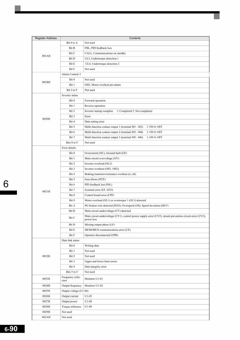
6-90
6
001AH
Bit 8 to A Not used
Bit B FBL, PID feedback loss
Bit C CALL, Communications on standby
Bit D UL3, Undertorque detection 1
Bit E UL4, Undertorque detection 2
Bit F Not used
001BH
Alarm Content 3
Bit 0 Not used
Bit 1 OH3, Motor overheat pre-alarm
Bit 2 to F Not used
0020H
Inverter status
Bit 0 Forward operation
Bit 1 Reverse operation
Bit 2 Inverter startup complete 1: Completed 2: Not completed
Bit 3 Error
Bit 4 Data setting error
Bit 5 Multi-function contact output 1 (terminal M1 - M2) 1: ON 0: OFF
Bit 6 Multi-function contact output 2 (terminal M3 - M4) 1: ON 0: OFF
Bit 7 Multi-function contact output 3 (terminal M5 - M6) 1: ON 0: OFF
Bits 8 to F Not used
0021H
Error details
Bit 0 Overcurrent (OC), Ground fault (GF)
Bit 1 Main circuit overvoltage (OV)
Bit 2 Inverter overload (OL2)
Bit 3 Inverter overheat (OH1, OH2)
Bit 4 Braking transistor/resistance overheat (rr, rH)
Bit 5 Fuse blown (PUF)
Bit 6 PID feedback lost (FbL)
Bit 7 External error (EF, EFO)
Bit 8 Control board error (CPF)
Bit 9 Motor overload (OL1) or overtorque 1 (OL3) detected
Bit A PG broken wire detected (PGO), Overspeed (OS), Speed deviation (DEV)
Bit B Main circuit undervoltage (UV) detected
Bit C Main circuit undervoltage (UV1), control power supply error (UV2), inrush prevention circuit error (UV3), power loss
Bit D Missing output phase (LF)
Bit E MEMOBUS communications error (CE)
Bit F Operator disconnected (OPR)
0022H
Data link status
Bit 0 Writing data
Bit 1 Not used
Bit 2 Not used
Bit 3 Upper and lower limit errors
Bit 4 Data integrity error
Bits 5 to F Not used
0023H Frequency refer-ence Monitors U1-01
0024H Output frequency Monitors U1-02
0025H Output voltage (U1-06)
0026H Output current U1-03
0027H Output power U1-08
0028H Torque reference U1-09
0029H Not used
002AH Not used
Register Address. Contents

6
Note: Communications error details are stored until an error reset is input (you can also reset while the Unit is operating).
002BH
Control terminals input status
Bit 0 Input terminal S1 1: ON 0: OFF
Bit 1 Input terminal S2 1: ON 0: OFF
Bit 2 Multi-function input terminal S3 1: ON 0: OFF
Bit 3 Multi-function input terminal S4 1: ON 0: OFF
Bit 4 Multi-function input terminal S5 1: ON 0: OFF
Bit 5 Multi-function input terminal S6 1: ON 0: OFF
Bit 6 Multi-function input terminal S7 1: ON 0: OFF
Bits 7 to F Not used
002CH
Inverter status
Bit 0 Operation 1: Operating
Bit 1 Zero speed 1: Zero speed
Bit 2 Frequency agree 1: Agreement
Bit 3 User-defined speed agree 1: Agreement
Bit 4 Frequency detection 1 1: Output frequency ≤ L4-01
Bit 5 Frequency detection 2 1: Output frequency ≥ L4-01
Bit 6 Inverter startup completed 1: Startup completed
Bit 7 Undervoltage detection 1: Detected
Bit 8 Baseblock 1: Inverter output baseblock
Bit 9 Frequency reference mode 1: Not communication 0: Communication option
Bit A Run command mode 1: Not communication 0: Communication option
Bit B Overtorque detection 1: Detected
Bit C Frequency reference lost 1: Lost
Bit D Restart enabled1: Restarting
Bit E Error (including MEMOBUS communications time-out) 1:Error occurred
Bit F MEMOBUS communications time-out 1: Timed out
002DH
Multi-function contact output status
Bit 0 Multi-function contact output 1 (terminal M1-M2) 1: ON 0: OFF
Bit 1 Multi-function contact output 2 (terminal M3-M4) 1: ON 0: OFF
Bit 2 Multi-function contact output 3 (terminal M5-M6) 1: ON 0: OFF
Bits 3 to F Not used
002EH - 0030H Not used
0031H Main circuit DC voltage
0032H - 0037H Not used
0038H PID feedback (max. output frequency = 100%; resolution 0.1%; without sign)
0039H PID input (max. output frequency = 100%; resolution 0.1%; with sign)
003AH PID output (max. output frequency = 100%; resolution 0.1%; with sign)
003BH CPU software number
003CH Flash software number
003DH
Communications error details
Bit 0 CRC error
Bit 1 Invalid data length
Bit 2 Not used
Bit 3 Parity error
Bit 4 Overrun error
Bit 5 Framing error
Bit 6 Time-out
Bits 7 to F Not used
003EH kVA setting
003FH Control method
Register Address. Contents
6-91

6-92
6
Broadcast DataUsing broadcast data a command can be given to all slaves at the same time. The slave address in the com-mand message must be set to 00H. All slaves will receive the message. They will not respond.
The following table shows the broadcast data. You can also write this data.
Note:Bit signals not defined in the broadcast operation signals use the local inverter input/output signals.* A change of these bits to 1 will be accepted only, if the bits C,D and/or E in register 000FH (reference data) are set to 1 at the inverter, at which the inputs
S5, S6 and S7 shall be enabled.
Inverter Error CodesThe content of a current fault and faults that have occurred earlier can be read out by Memobus using the FaultTrace (U2- ) and the Fault History (U3- ) parameters. The fault codes are shown in the table below.
Refer to page 7-2, Fault Detection for detailed fault descriptions and for corrective actions.
Register Address Contents
0001H
Operation signal
Bit 0 Forward run
Bit 1 Reverse run
Bits 2 and 3 Not used
Bit 4 External error 1
Bit 5 Error reset 1
Bits 6 to B Not used
Bit C *1 Multi-function digital input terminal S5 input
Bit D *1 Multi-function digital input terminal S6 input
Bit E *1 Multi-function digital input terminal S7 input
Bit F Not used.
0002H Frequency reference
Fault Code Fault Description Fault Code Fault Description Fault Code Fault Description01H PUF 13H EF5 28H FBL02H UV1 14H EF6 29H UL303H UV2 15H EF7 2AH UL404H UV3 18H OS 2BH OL706H GF 19H DEV 83H CPF0207H OC 1AH PGO 84H CPF0308H OV 1BH PF 85H CPF0409H OH 1CH LF 86H CPF050AH OH1 1DH OH3 87H CPF060BH OL1 1EH OPR 88H CPF070CH OL2 1FH ERR 89H CPF080DH OL3 20H OH4 8AH CPF090EH OL4 21H CE 8BH CPF100FH RR 22H BUS 91H CPF2010H RH 25H CF 92H CPF2111H EF3 26H SVE 93H CPF2212H EF4 27H EF0 94H CPF23

6
ENTER CommandWhen writing parameters to the Inverter from the PLC using MEMOBUS communications, the parameters aretemporarily stored in the parameter data area of the Inverter. To enable these parameters in the parameter dataarea the ENTER command must be used.
There are two types of ENTER commands: • ENTER commands that enable parameter data in RAM only (changes will be lost after power loss)• ENTER commands that write data into the EEPROM (non-volatile memory) of the Inverter and enable the
data in RAM at the same time.
The following table shows the ENTER command data. ENTER command data can only be written.
The ENTER command is enabled by writing 0 to register number 0900H or 0910H.
Error CodesThe following table shows MEMOBUS communications error codes.
Register Address. Contents0900H Write parameter data to EEPROM, RAM is refreshed
0910H Parameter data are not written to EEPROM, but refreshed in RAM only.
INFO
• The maximum number of times you can write to EEPROM is 100,000. Do not frequently execute ENTER com-mands (0900H) that write into EEPROM.
• The ENTER command registers are write-only. Consequently, if these registers should be read out, the register address will become invalid (Error code: 02H).
• An ENTER command is not required if reference or broadcast data are sent to the inverter.
Error Code Contents
01H Function code errorA function code other than 03H, 08H, or 10H has been set by the PLC.
02HInvalid register number error• The register address you are attempting to access is not recorded anywhere.• With broadcast sending, a start address other than 0001H, or 0002H has been set.
03HInvalid quantity error• The number of data packets (register content) being read or written is outside the range of 1 to 16.• In write mode, the number of data bytes in the message is not No. of packets x 2.
21HData setting error• A simple upper limit or lower limit error has occurred in the control data or when writing parameters.• When writing parameters, the parameter setting is invalid.
22H
Write mode error• Attempting to write parameters to the inverter during operation.• Attempting to write via ENTER commands during operation.• Attempting to write parameters other than A1-00 to A1-05, E1-03, or 02-04 when warning alarm CPF03
(defective EEPROM) has occurred.• Attempting to write read-only data.
23HWriting during DC bus undervoltage (UV) error• Writing parameters to the inverter during UV (DC bus undervoltage) alarm.• Writing via ENTER commands during UV (DC bus undervoltage) alarm.
24H Writing error during parameters processingAttempting to write parameters while processing parameters in the Inverter.
6-93

6-94
6
Slave Not RespondingIn the following cases, the slave will ignore the write function.
• When a communications error (overrun, framing, parity, or CRC-16) is detected in the command message.• When the slave address in the command message and the slave address in the Inverter do not agree.• When the gap between two blocks (8 bit) of a message exceeds 24 bits.• When the command message data length is invalid.
Self-DiagnosisThe Inverter has a built-in function for self-diagnosing the serial communication interface circuits. This func-tion is called the self-diagnosis function. It uses the connected communications parts of the send and receiveterminals to receive data sent by the Inverter and thereby to check if communication is performed normally.
To perform the self-diagnosis function use the following procedure.
1. Turn ON the inverter power supply, and set 67 (communications test mode) in parameter H1-05 (TerminalS7 Function Selection).
2. Turn OFF the inverter power supply.3. Perform the wiring according to Fig 6.77.4. Turn ON the terminating resistance. (Turn ON pin 1 on DIP switch 1.)5. Turn ON the inverter power supply.
Fig 6.77 Communication Terminals Wiring for Self-Diagnosis
During normal operation, the Digital Operator displays “PASS” on the display.
If an error occurs, a “CE” (MEMOBUS communications error) alarm will be displayed on the Digital Opera-tor, the error contact output will be turned ON, and the Inverter operation ready signal will be turned OFF.
INFO
If the slave address specified in the command message is 0, all slaves execute the write function, but do not return response messages to the master.

6
Using the Timer Function
The multi-function digital input terminals S3 to S7 can be used as timer function input terminals, and multi-function output terminals M1-M2, M3-M4, and M5-M6 can be used as timer function output terminals. Bysetting the delay time, you can prevent chattering of the sensors and switches.
• Set one of the parameters H1-01 to H1-05 (digital input terminal S3 to S7) to 18 (timer function input).• Set H2-01 to H2-03 (multi-function output terminals M1-M2, M3-M4, and M5-M6 function selection) to
12 (timer function output).
Related Parameters
Multi-function Digital Inputs (H1-01 to H1-05)
Multifunction Outputs (H2-01 to H2-03)
Setting ExampleWhen the timer function input ON time is longer than the value set in b4-01, the timer output function isturned ON. When the timer function input OFF time is longer than the value set in b4-02, the timer outputfunction is turned OFF. An example of timer function operation is given in the following diagram.
Fig 6.78 Timer Function Operation Example
Parameter No. Name Factory
Setting
Change during Opera-
tion
Control Methods
V/f V/f with PG
Open Loop
Vector
Closed Loop
Vectorb4-01 Timer function ON-delay time 0.0 s No A A A A
b4-02 Timer function OFF-delay time 0.0 s No A A A A
Set Value Function
Control Methods
V/fV/f
with PG
Open Loop
Vector
Closed Loop
Vector18 Timer function input Yes Yes Yes Yes
Set Value Function
Control Methods
V/fV/f
with PG
Open Loop
Vector
Closed Loop
Vector12 Timer function output Yes Yes Yes Yes
Timer function input
Timer function output
6-95
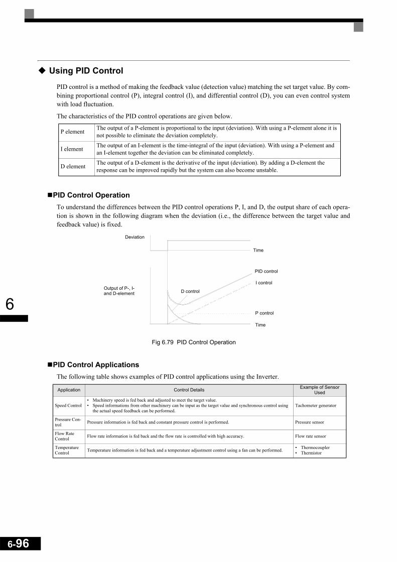
6-96
6
Using PID Control
PID control is a method of making the feedback value (detection value) matching the set target value. By com-bining proportional control (P), integral control (I), and differential control (D), you can even control systemwith load fluctuation.
The characteristics of the PID control operations are given below.
PID Control OperationTo understand the differences between the PID control operations P, I, and D, the output share of each opera-tion is shown in the following diagram when the deviation (i.e., the difference between the target value andfeedback value) is fixed.
Fig 6.79 PID Control Operation
PID Control ApplicationsThe following table shows examples of PID control applications using the Inverter.
P element The output of a P-element is proportional to the input (deviation). With using a P-element alone it is not possible to eliminate the deviation completely.
I element The output of an I-element is the time-integral of the input (deviation). With using a P-element and an I-element together the deviation can be eliminated completely.
D element The output of a D-element is the derivative of the input (deviation). By adding a D-element the response can be improved rapidly but the system can also become unstable.
Application Control Details Example of Sensor Used
Speed Control• Machinery speed is fed back and adjusted to meet the target value.• Speed informations from other machinery can be input as the target value and synchronous control using
the actual speed feedback can be performed.Tachometer generator
Pressure Con-trol Pressure information is fed back and constant pressure control is performed. Pressure sensor
Flow Rate Control Flow rate information is fed back and the flow rate is controlled with high accuracy. Flow rate sensor
Temperature Control Temperature information is fed back and a temperature adjustment control using a fan can be performed. • Thermocoupler
• Thermistor
Deviation
Output of P-, I-D control
Time
PID control
I control
P control
Time
and D-element
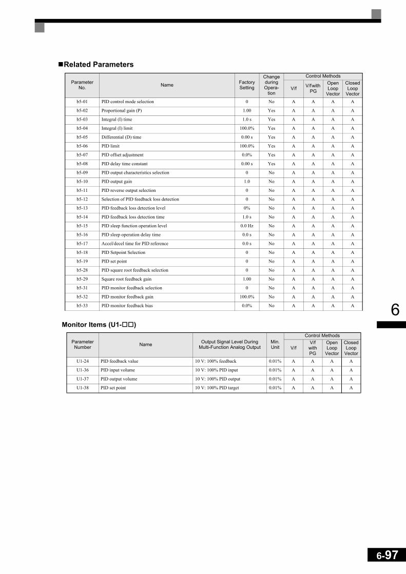
6
Related Parameters
Monitor Items (U1- )
Parameter No. Name Factory
Setting
Change during Opera-
tion
Control Methods
V/f V/f with PG
Open Loop
Vector
Closed Loop
Vectorb5-01 PID control mode selection 0 No A A A A
b5-02 Proportional gain (P) 1.00 Yes A A A A
b5-03 Integral (I) time 1.0 s Yes A A A A
b5-04 Integral (I) limit 100.0% Yes A A A A
b5-05 Differential (D) time 0.00 s Yes A A A A
b5-06 PID limit 100.0% Yes A A A A
b5-07 PID offset adjustment 0.0% Yes A A A A
b5-08 PID delay time constant 0.00 s Yes A A A A
b5-09 PID output characteristics selection 0 No A A A A
b5-10 PID output gain 1.0 No A A A A
b5-11 PID reverse output selection 0 No A A A A
b5-12 Selection of PID feedback loss detection 0 No A A A A
b5-13 PID feedback loss detection level 0% No A A A A
b5-14 PID feedback loss detection time 1.0 s No A A A A
b5-15 PID sleep function operation level 0.0 Hz No A A A A
b5-16 PID sleep operation delay time 0.0 s No A A A A
b5-17 Accel/decel time for PID reference 0.0 s No A A A A
b5-18 PID Setpoint Selection 0 No A A A A
b5-19 PID set point 0 No A A A A
b5-28 PID square root feedback selection 0 No A A A A
b5-29 Square root feedback gain 1.00 No A A A A
b5-31 PID monitor feedback selection 0 No A A A A
b5-32 PID monitor feedback gain 100.0% No A A A A
b5-33 PID monitor feedback bias 0.0% No A A A A
Parameter Number Name Output Signal Level During
Multi-Function Analog OutputMin. Unit
Control Methods
V/fV/f
with PG
Open Loop
Vector
Closed Loop
VectorU1-24 PID feedback value 10 V: 100% feedback 0.01% A A A A
U1-36 PID input volume 10 V: 100% PID input 0.01% A A A A
U1-37 PID output volume 10 V: 100% PID output 0.01% A A A A
U1-38 PID set point 10 V: 100% PID target 0.01% A A A A
6-97

6-98
6
Multi-Function Digital Inputs (H1-01 to H1-05)
Multi-Function Analog Input (H3-09)
Pulse Train Input (H6-01)
PID Control Methods (b5-01)There are four PID control methods. Select the method by setting parameter b5-01.
Set Value Function
Control Methods
V/fV/f
with PG
Open loop
Vector
Closed Loop
Vector19 PID control disable (ON: PID control disabled) Yes Yes Yes Yes
30 PID control integral reset (reset when reset command is input or when stopped during PID control) Yes Yes Yes Yes
31 PID control integral hold (ON: Integral hold) Yes Yes Yes Yes
34 PID soft starter Yes Yes Yes Yes
35 PID input characteristics switch Yes Yes Yes Yes
Set Value Function
Control Methods
V/fV/f
with PG
Open loop
Vector
Closed Loop
VectorB PID feedback Yes Yes Yes Yes
C PID target value Yes Yes Yes Yes
Set Value Function
Control Methods
V/fV/f
with PG
Open Loop
Vector
Closed Loop
Vector0 Frequency reference Yes Yes Yes Yes
1 PID feedback value Yes Yes Yes Yes
2 PID target value Yes Yes Yes Yes
Set Value Control Method
1 PID output becomes the Inverter output frequency, and D control is used in the deviation (difference between PID target value and feedback value.)
2 PID output becomes the Inverter output frequency, and D control is used in the PID feedback value.
3 PID output is added as compensation value of the Inverter output frequency, and D control is used in the deviation (difference between PID target value and feedback value).
4 PID output is added as compensation value of the Inverter output frequency, and D control is used in the PID feedback value.

6
PID Input Methods
PID Target Value Input SourcesNormally, the frequency reference source selected in b1-01 is the PID target value source. Alternatively thePID target value can be set as shown in the following table.
PID Feedback Input MethodsSelect one of the following PID control feedback input methods
PID Target Input Method Setting Conditions
Multi-Function Analog Terminal A2 Input
Set H3-09 to C (PID target value). Either the pulse train input or the analog input A1 can be selected as PID feed-back value.
MEMOBUS register 0006H Set MEMOBUS bit 1 in register address 000FH to 1 (enable/disable PID target value from communications) to be able to use register number 0006H as the PID target value.
Pulse train input Set H6-01 to 2 (PID target value).
Parameter setting If b5-18 is set to 1 the value in b5-19 becomes the PID target value.
INFO
If the PID function is used, the frequency reference value becomes the target value, which is set and shown in Hz on the operator. Nevertheless, internally the PID target value is used in percent. I.e. the following formula is used:
Input Method Setting Conditions
Multi-function analog input Set H3-09 (Multi-function Analog Input Terminal A2 Selection) to B (PID feedback).
Pulse train input Set H6-01 to 1 (PID feedback).
Monitor Parameter Set the number of the monitor parameter U1- , which shall be the PID feedback, in parameter b5-31
INFO
Adjust PID target value and PID feedback value using the following items.• Analog input: Adjust using the analog input terminal gain and bias.• Pulse train input: Adjust using pulse train scaling, pulse train input gain, and pulse train input bias.
PID target value [%] = frequency reference [Hz]
max. output frequency [Hz]• 100%
6-99

6-100
6
PID Adjustment Examples
Suppressing OvershootIf overshoot occurs, reduce Proportional gain (P), and increase integral time (I).
Set a Rapidly Stabilizing Control ConditionTo rapidly stabilize the control even if overshoot occurs, reduce integral time (I), and lengthen differentialtime (D).
Suppressing Long-cycle VibrationIf vibration occurs with a longer cycle than the integral time (I) set value, lengthen the integral time (I) to sup-press the vibration.
Suppressing Short Cycle VibrationIf vibration occurs when the vibration cycle duration is short, and the cycle duration is almost identical to thedifferential time (D) set value, the differential operation is too strong. Shorten the differential time (D) to sup-press the vibration.
If vibration continues even when the differential time (D) is set to 0.00 (D control disabled), reduce the pro-portional gain (P), or increase the PID primary delay time constant.
Response Before adjustment
After adjustment
Time
ResponseBefore adjustment
After adjustment
Time
Response Before adjustment
After adjustment
Time
Response Before adjustment
After adjustment
Time
6
Setting Precautions• In PID control, the b5-04 parameter is used to prevent the calculated integral control value from exceeding
a specified amount. When the load varies rapidly, the Inverter response is delayed, and the machine mightget be damaged or the motor may stall. In this case, reduce the set value to speed up Inverter response.
• The b5-06 parameter is used to prevent the output value of the PID control calculation from exceeding aspecified amount. The value is set taking the maximum output frequency as 100%.
• The b5-07 parameter is used to adjust PID control offset. The value is set in increments of 0.1%, taking themaximum output frequency to be 100%.
• Set the filter time constant for the PID control output in b5-08. Enable this parameter to prevent machineryresonance when machinery friction is high, or rigidity is poor. In this case, set the parameter to be higherthan the resonance frequency cycle duration. Increase this time constant to reduce Inverter responsiveness.
• Using b5-09, the PID output polarity can be inverted. If now the PID feedback value increases the outputfrequency will be increased. This function is usable e.g. for vacuum pumps.
• Using b5-10, you can apply a gain to the PID control output. Enable this parameter to adjust the amount ofcompensation if adding PID control output to the frequency reference as compensation (b5-01 = 3/4).
• When PID control output is negative, you can use parameter b5-11 to determine what happens to theinverter output. When b1-04 (Prohibition of Reverse Operation) is set to 1 (enabled), however, the PIDoutput is limited to 0.
• Using the b5-17 parameter the PID target value can be raised or lowered with an accel./decel. ramp func-tion (PID soft starter).The normally used accel./decel. function (C1- parameters) is allocated after PID control so that,depending on the settings, resonance with the PID control and hunting in the machinery may occur. Usingb5-17 this behavior can be prevented.The PID soft starter function can also be disabled or enabled using a multifunction digital input (H1-has to be set to 34).
6-101

6-102
6
PID Control BlockThe following diagram shows the PID control block in the Inverter.
Fig 6.80 PID Control Block Diagram
Opt
ion
Car
d
Ser
ial C
om
Ana
log
Inpu
t A1/
A2*
Pul
se T
rain
Inp.
D1-
16
D1-
02
Out
put
frequ
ency
P1/
t1/
t
Z-1
b1-0
1
123
Freq
uenc
y R
efer
ence
usin
g m
ulti-
step
com
man
d
Freq
uenc
y re
fere
nce
(U1-
01)
PID
Set
Poi
nt(U
1-38
)
Pro
porti
onal
gain
b5-0
2I-t
ime
b5-0
3I -
lim
itb5
-04
PID
Lim
itb5
-06
PID
del
ay ti
me
b5-0
8
+++
+
b5-0
1=0
ON
PID
con
trol i
s O
FF u
nder
the
follo
win
g co
nditi
ons:
- b5-
01=0
- Dur
ing
JOG
com
man
d is
inpu
t- H
3-=1
9 an
d th
e te
rmin
al s
tatu
s is
ON
Upp
er li
mit
Fmax
x10
9%
+
+
b5-0
1=3
or 4
b5-0
1=1
or 2
Upp
er li
mit
Fmax
x10
9%
Low
er li
mit
Fmax
x10
9%Low
er li
mit
0
0
ME
MO
BU
S R
eg. 0
6HPI
D ta
rget
val
ue
Inte
gral
Hol
dH
1-=3
1In
tegr
al R
eset
H1-
=30
PID
Out
put
Car
acte
ristic
b5-0
9
b5-1
110
Ena
ble
/ Dis
able
reve
rse
oper
atio
nw
hen
PID
out
put i
s ne
gativ
Con
stan
t b5-
19b5
-18=
1
0
PID
SFS
b5-1
7
PID
SFS
can
cel
H1-
=34
01
Freq
uenc
y R
efer
ence
/ PI
D T
arge
t
PID
Tar
get
o1-0
3Scal
ing
1R
eg. 0
Fh, b
it 1
PID
Fee
dbac
k
Term
inal
A2/
A1*
H3-
09=B
10
Z-1
10
10
PID
Inpu
tC
hara
cter
istic
H1-
=35
10
Z-1
PID
SFS
b5-1
7
PID
SFS
can
cel
H1-
=34 01
PID
Inpu
t(U
1-36
)
+ -10
b5-2
8
PID
Fee
dbac
k(U
1-24
)
b5-0
7
++
-+b5
-10
PID
Out
put
Gai
n
PID
offs
et
+ -
b5-1
5S
leep
Lev
el
RU
Non
/off
b5-1
6D
elay
Tim
er
Slee
p Fu
nctio
n
SFS
OFF
P
b5-2
9
4D
1-01
Puls
Tra
in In
put
PID
targ
et v
alue
Anal
og In
put A
2/A
1*
H6-
01=2
H3-
09=C
Puls
e Tr
ain
Inp.
PID
Mon
itor
Feed
back
Sel
.U
1-B
5-31
0
H6-
01=1
Z-1
b5-0
5+ +
1 or
3 2 or
4b5
-01
Diff
eren
tial
Tim
e
* If a
nalo
g in
put A
2 is
set
as
mas
ter r
efer
ence
inpu
t (H
3-13
=1),
ana
log
inpu
t A1
can
be s
elec
ted
for P
ID ta
rget
or P
ID f
eedb
ack
usin
g p
aram
eter
H3-
09
H3-
09
B
H6-
01
1
B5-
31=0
H3-
09
C
b5-1
8 =
1
H6-
01
2
Z-1
b5-0
5b5
-01
2 or
4
1 or
3
+ ++ +
Squ
are
Roo
tFe
edba
ck
PID
out
put m
onito
r(U
1-37
)
b5-2
81
0S
quar
e R
oot
Feed
back
Mon
itor
-200
%
200%
3 or
41
or 2
b5-0
1

6
PID Feedback Loss Detection When performing PID control, be sure to use the PID feedback loss detection function. Otherwise if the PIDfeedback gets lost, the Inverter output frequency may accelerate to the maximum output frequency.
Low Feedback (b5-12 = 1 or 2)When b5-12 is set to 1 and the PID feedback value falls below the PID feedback loss detection level (b5-13)for a time longer than the PID feedback loss detection time (b5-14), a “FBL - Feedback Loss” alarm will bedisplayed at the operator and inverter operation is continued.
When the same happens and b5-12 is set to 2 a “FBL - Feedback Loss” fault will be displayed on the digitaloperator and the inverter operation will be stopped. The motor coasts to stop and the fault contact is operated.
The time chart for PID feedback loss detection is shown below.
Fig 6.81 Low PID Feedback Loss Detection Time Chart
High Feedback (b5-12 = 3 or 4)When b5-12 is set to 3 and the PID feedback value exceeds the PID feedback loss detection level (b5-13) for atime longer than the PID feedback loss detection time (b5-14), a “FBL - Feedback Loss” alarm will be dis-played at the operator and inverter operation is continued.
When the same happens and b5-12 is set to 4 a “FBL - Feedback Loss” fault will be displayed on the digitaloperator and the inverter operation will be stopped. The motor coasts to stop and the fault contact is operated.
The time chart for PID feedback loss detection is shown below.
Fig 6.82 High PID Feedback Loss Detection Time Chart
PID feedback value
Time
Fbl detection
Loss detection level (b5-13)
Loss detection time(b5-14)
Loss detection time’(b5-14)
No Fbldetection
PID feedback value
Time
Fbl detection
Loss detection level (b5-13)
Loss detection time(b5-14)
Loss detection time(b5-14)
No Fbldetection
6-103

6-104
6
PID SleepThe PID sleep function stops the Inverter when the PID output value falls below the sleep operation level (b5-15) for the sleep operation time set in parameter b5-16. The inverter operation will resume, if the PID outputvalue exceeds the sleep operation level for the time set in parameter b5-16 or longer.
The PID sleep function works as well when the PID control is disabled. In this case the frequency referencevalue is observed by the sleep function instead of the PID output value.
The PID sleep time chart is shown below.
Fig 6.83 PID Sleep Time Chart
Square Root Feedback OperationIf parameter b5-28 is set to 1, the feedback value is converted into a value that equals the square root of theactual feedback. This can be used to control the flow rate when a pressure sensor is used to generate a feed-back value. Using parameter b5-29 the square root feedback can be multiplied with a factor. Following for-mula applies:
So linear connection between the PID target value and the feedback can be realized.
PID Monitor Feedback FunctionUsing this function an internal monitor (U1- ) can be set as PID feedback value. The monitor item can beselected in parameter b5-31. The following set values are possible:
Set Value Function
Control Methods
V/f V/f with PG
Open loop
Vector
Closed Loop
Vector0 Disabled Yes Yes Yes Yes
3 Output current Yes Yes Yes Yes
5 Motor Speed No Yes Yes Yes
6 Output voltage Yes Yes Yes Yes
7 DC bus voltage Yes Yes Yes Yes
8 Output power Yes Yes Yes Yes
9 Torque reference No No Yes Yes
15 Terminal A1 input level Yes Yes Yes Yes
16 Terminal A2 input level Yes Yes Yes Yes
18 Motor secondary current Yes Yes Yes Yes
PID output value
Internal run command
External run commandOperating
Operation status outputRun command has been input
Stopped
Sleep operation lev-el b5-15
Sleep operation delay time
Sleep operation delay time
Operation
Flow rate Gain (b5-29) Pressure (head)×=

6
Multifunction Digital Input Settings: H1-01 to H1-05 (Terminal S3 to S7)
PID Control Disable: “19”• If a multifunction input is set for this function it can be used to disable the PID function by switching the
input to ON.• The PID target value becomes the frequency reference value.
PID Control Integral Reset: “30”• Using this function the integral share value of the PID control can be reset by setting a multifunction input
to ON.
PID Control Integral Hold: “31”• Using this function the integral share value of the PID control can be hold by setting a multifunction input
to ON. The value will be hold as long as the input is ON.
PID Softstarter Disable: “34”• Using this function the PID softstarter can be disabled or enabled. It is disabled if the input is activated.
PID Input Characteristic Switch: “35”• Using this function the PID input characteristic can be inverted by setting a multifunction input to ON.
6-105

6-106
6
Energy-saving
To use the energy saving function, set b8-01 (Energy Saving Mode Selection) to 1. Energy-saving control canbe performed in all control methods. The parameters to be adjusted are different for each. In the V/f controlmodes adjust b8-04 to b8-05. In Open Loop and Closed Loop Vector control adjust b8-02 and b8-03.
Related Parameters
* 1. The value for Open Loop Vector control is given. The factory setting is 1.0 in Closed Loop Vector control.* 2. The factory setting is 2.00 s for Inverters larger than 55 kW.* 3. The factory settings depend on the Inverter capacity.
Adjusting Energy-saving ControlThe method of adjusting the energy-saving control function depends on the control method. Refer to the fol-lowing when making adjustments.
V/f Control ModesIn the V/f control modes the voltage for optimum motor efficiency is calculated and becomes the output volt-age reference.
• b8-04 (Energy-saving Coefficient) is preset assuming that motor and inverter capacity are the same. If theinverter capacity differs from the motor capacity, set the motor capacity in E2-11 (Motor Rated OutputPower). Also, adjust b8-04 in steps of 5 % until the output power reaches its minimum. The higher theenergy-saving coefficient, the higher is the output voltage.
• To improve the responsiveness when the load fluctuates, reduce the power detection filter time parameterb8-05. If b8-05 is set too small, however, the motor rotations may become unstable under light load condi-tions.
• Motor efficiency varies due to temperature fluctuations and differences in motor characteristics. Conse-quently the motor efficiency has to be controlled. To have optimized efficiency, the search operation variesthe output voltage. Parameter b8-06 (Search Operation Voltage Limiter) limits the range for the voltagesearch operation. For 200 V Class Inverters, a range of 100% is equal to 200 V and for 400 V Class Invert-ers a range of 100% is equal to 400 V. Set b8-06 to 0 to disable the search operation voltage limiter.
Parameter No. Name Factory
Setting
Change during Opera-
tion
Control Methods
V/f V/f with PG
Open Loop
Vector
Closed Loop
Vectorb8-01 Energy-saving mode selection 0 No A A A A
b8-02 Energy-saving gain 0.7 *1 Yes No No A A
b8-03 Energy-saving filter time constant 0.50 s *2 Yes No No A A
b8-04 Energy-saving coefficient *3 No A A No No
b8-05 Power detection filter time constant 20 ms No A A No No
b8-06 Search operation voltage limiter 0% No A A No No
E2-02 Motor rated slip 2.90 Hz *3 No A A A A
E2-11 Motor rated output power 0.40 *3 No Q Q Q Q

6
Open Loop and Closed Loop Vector ControlIn Open Loop and Closed Loop Vector control, the slip frequency is controlled so that motor efficiency ismaximized.
• Taking the motor rated slip for the base frequency as optimum slip, the inverter calculates the slip for theoptimal motor efficiency depending on the output frequency.
• Before using energy saving always perform autotuning.• If hunting occurs reduce the set value in b8-02 (Energy-saving Gain), or increase the set value in b8-03
(Energy-saving Filter Time Constant).
Field Weakening
The field weakening function is used to lower the output voltage when the motor load changes to a low level(no load). Thereby energy can be saved and motor audible noise is reduced.
Note that this function is designed for the usage with one low load condition that does not change. If the lowload condition changes, the field weakening function can not be optimized. In this case the energy savingfunction should be preferred.
The function can be activated using a multifunction input. Therefore set one of the parameters H1-01 to H1-05to 63.Field weakening can be used in the V/f control modes only.
Related Parameters
Multi-function Digital Inputs (H1-01 to H1-05)
Setting the Field Weakening Level (d6-01)To set the field weakening level run the motor under low load condition and activate the field weakening func-tion using a multifunction input. Monitor the output current and raise or lower the field weakening level untilthe output current reaches it’s minimum value.
Observe the following:• Parameter d6-01 can not be changed during operation (i.e. a RUN command is input).• If the field weakening level is set too low, the motor may stall.
Activating Field WeakeningIf one of the parameters H1-01 to H1-05 is set to “63”, the field weakening function can be activated switchingthe regarding terminal input to ON.
Parameter No. Name Factory
Setting
Change during Opera-
tion
Control Methods
V/f V/f with PG
Open Loop
Vector
Closed Loop
Vectord6-01 Field weakening level 80% No A A No No
d6-02 Field weakening frequency limit 0.0 Hz No A A No No
Set Value Function
Control Methods
V/fV/f with PG
Open Loop
Vector
Closed Loop
Vector63 Field Weakening Yes Yes No No
6-107
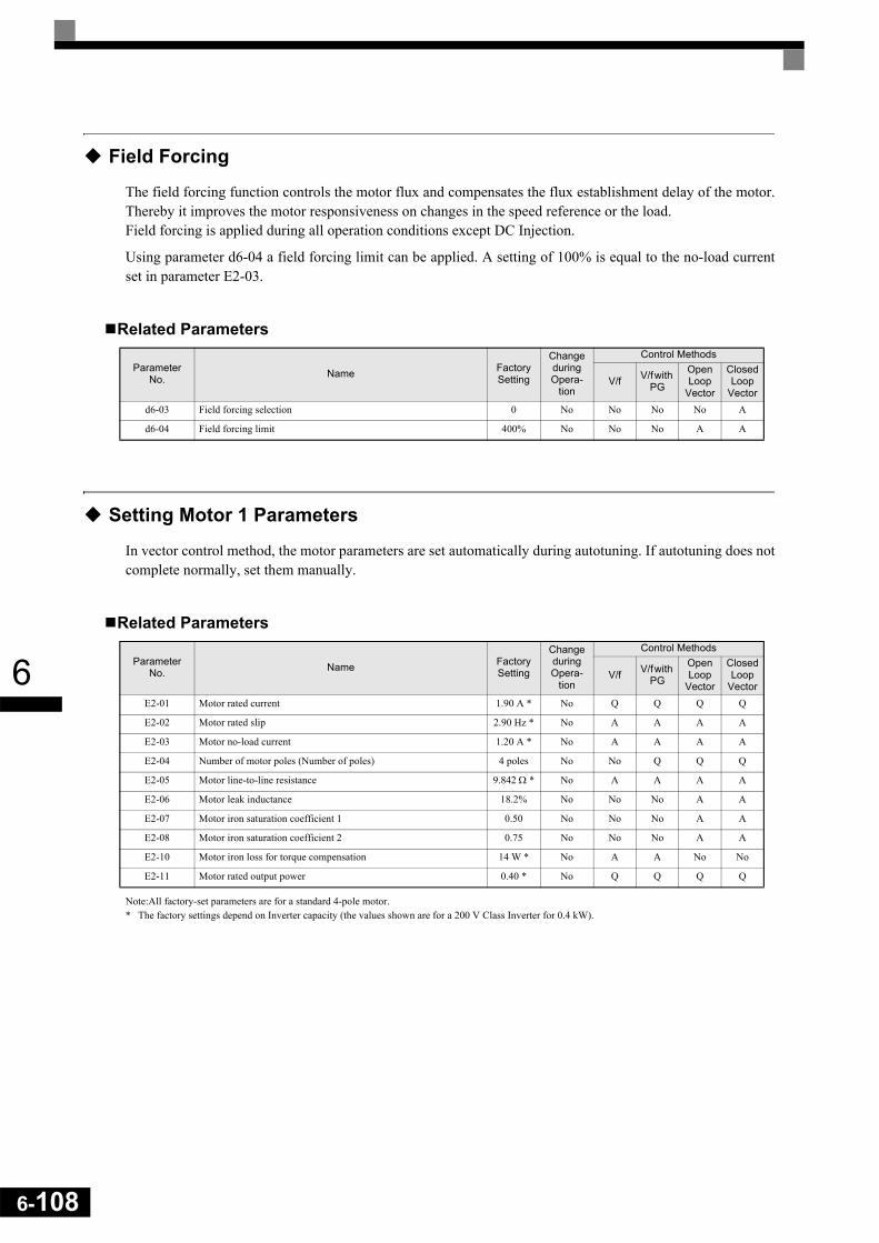
6-108
6
Field Forcing
The field forcing function controls the motor flux and compensates the flux establishment delay of the motor.Thereby it improves the motor responsiveness on changes in the speed reference or the load. Field forcing is applied during all operation conditions except DC Injection.
Using parameter d6-04 a field forcing limit can be applied. A setting of 100% is equal to the no-load currentset in parameter E2-03.
Related Parameters
Setting Motor 1 Parameters
In vector control method, the motor parameters are set automatically during autotuning. If autotuning does notcomplete normally, set them manually.
Related Parameters
Note:All factory-set parameters are for a standard 4-pole motor.* The factory settings depend on Inverter capacity (the values shown are for a 200 V Class Inverter for 0.4 kW).
Parameter No. Name Factory
Setting
Change during Opera-
tion
Control Methods
V/f V/f with PG
Open Loop
Vector
Closed Loop
Vectord6-03 Field forcing selection 0 No No No No A
d6-04 Field forcing limit 400% No No No A A
Parameter No. Name Factory
Setting
Change during Opera-
tion
Control Methods
V/f V/f with PG
Open Loop
Vector
Closed Loop
VectorE2-01 Motor rated current 1.90 A * No Q Q Q Q
E2-02 Motor rated slip 2.90 Hz * No A A A A
E2-03 Motor no-load current 1.20 A * No A A A A
E2-04 Number of motor poles (Number of poles) 4 poles No No Q Q Q
E2-05 Motor line-to-line resistance 9.842 Ω * No A A A A
E2-06 Motor leak inductance 18.2% No No No A A
E2-07 Motor iron saturation coefficient 1 0.50 No No No A A
E2-08 Motor iron saturation coefficient 2 0.75 No No No A A
E2-10 Motor iron loss for torque compensation 14 W * No A A No No
E2-11 Motor rated output power 0.40 * No Q Q Q Q

6
Manual Setting of the Motor Parameters
Motor Rated Current Setting (E2-01)Set E2-01 to the rated current value on the motor nameplate.
Motor Rated Slip Setting (E2-02)Set E2-02 to the motor rated slip calculated from the number of rated rotations on the motor nameplate.
Motor No-Load Current Setting (E2-03)Set E2-03 to the motor no-load current at the rated voltage and rated frequency. Normally, the motor no-loadcurrent is not written on the motor nameplate. Consult the motor manufacturer.
Factory setting is the no-load current value for a standard 4-pole motor.
Number of Motor Poles Setting (E2-04)E2-04 is displayed in V/f control with PG, Open Loop and Closed Loop Vector mode only. Set the number ofmotor poles as written on the motor nameplate.
Motor Line-to-Line Resistance Setting (E2-05)E2-05 is set automatically when performing motor line-to-line resistance autotuning. When you cannot per-form tuning, consult the motor manufacturer for the line-to-line resistance value. Calculate the resistance fromthe line-to-line resistance value in the motor test report using the following formula, and then make the settingaccordingly.
• E-type insulation: [Line-to line resistance (Ω) at 75°C of test report] × 0.92 (Ω)• B-type insulation: [Line-to line resistance (Ω) at 75°C of test repor]t × 0.92 (Ω)• F-type insulation: [Line-to line resistance (Ω) at 115°C of test report] × 0.87 (Ω)
Motor Leak Inductance Setting (E2-06)Set the amount of voltage drop due to motor leakage inductance in E2-06 as percentage of the motor ratedvoltage. Make this setting when using high-speed motors because the standard value will be too high. (Nor-mally, high speed motors have a low inductance compared to standard motors.) If the inductance is not writtenon the motor nameplate, consult the motor manufacturer.
Motor Iron Saturation Coefficients 1 and 2 Settings (E2-07)E2-07 and E2-08 are set automatically during rotating autotuning.
Motor Iron Loss for Torque Compensation Setting (E2-10)E2-10 is displayed only in V/f control method and can be set to increase the torque compensation accuracy.The motor iron loss has to be set in kW.
Motor Rated Slip Motor rated frequency (Hz) Rated Speed (rpm) No. of motor poles×120
-------------------------------------------------------------------------------------------------–=
6-109
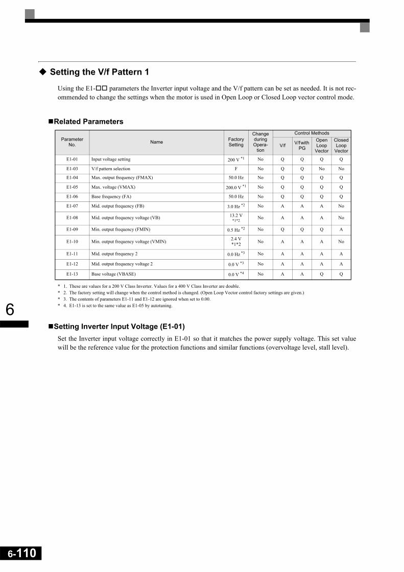
6-110
6
Setting the V/f Pattern 1
Using the E1- parameters the Inverter input voltage and the V/f pattern can be set as needed. It is not rec-ommended to change the settings when the motor is used in Open Loop or Closed Loop vector control mode.
Related Parameters
* 1. These are values for a 200 V Class Inverter. Values for a 400 V Class Inverter are double.* 2. The factory setting will change when the control method is changed. (Open Loop Vector control factory settings are given.)* 3. The contents of parameters E1-11 and E1-12 are ignored when set to 0.00.* 4. E1-13 is set to the same value as E1-05 by autotuning.
Setting Inverter Input Voltage (E1-01)Set the Inverter input voltage correctly in E1-01 so that it matches the power supply voltage. This set valuewill be the reference value for the protection functions and similar functions (overvoltage level, stall level).
Parameter No. Name Factory
Setting
Change during Opera-
tion
Control Methods
V/f V/f with PG
Open Loop
Vector
Closed Loop
Vector
E1-01 Input voltage setting 200 V *1 No Q Q Q Q
E1-03 V/f pattern selection F No Q Q No No
E1-04 Max. output frequency (FMAX) 50.0 Hz No Q Q Q Q
E1-05 Max. voltage (VMAX) 200.0 V *1 No Q Q Q Q
E1-06 Base frequency (FA) 50.0 Hz No Q Q Q Q
E1-07 Mid. output frequency (FB) 3.0 Hz *2 No A A A No
E1-08 Mid. output frequency voltage (VB) 13.2 V *1*2
No A A A No
E1-09 Min. output frequency (FMIN) 0.5 Hz *2 No Q Q Q A
E1-10 Min. output frequency voltage (VMIN) 2.4 V*1*2 No A A A No
E1-11 Mid. output frequency 2 0.0 Hz *3 No A A A A
E1-12 Mid. output frequency voltage 2 0.0 V *3 No A A A A
E1-13 Base voltage (VBASE) 0.0 V *4 No A A Q Q
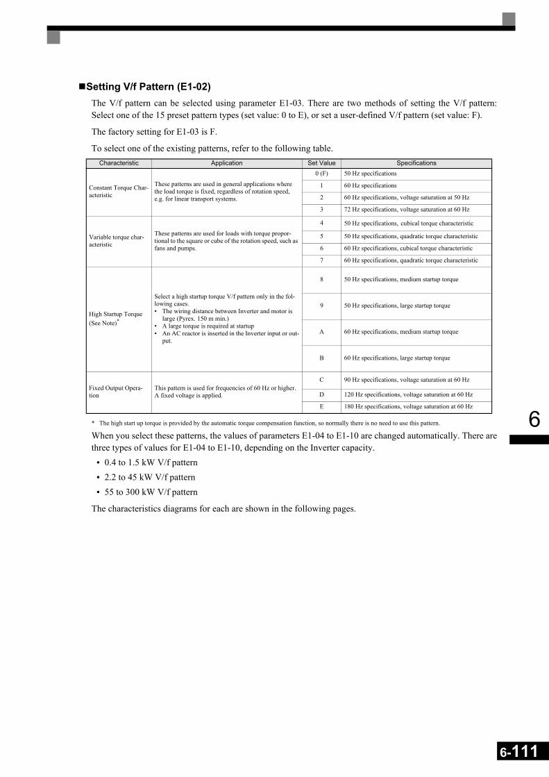
6
Setting V/f Pattern (E1-02)The V/f pattern can be selected using parameter E1-03. There are two methods of setting the V/f pattern:Select one of the 15 preset pattern types (set value: 0 to E), or set a user-defined V/f pattern (set value: F).
The factory setting for E1-03 is F.
To select one of the existing patterns, refer to the following table.
* The high start up torque is provided by the automatic torque compensation function, so normally there is no need to use this pattern.
When you select these patterns, the values of parameters E1-04 to E1-10 are changed automatically. There arethree types of values for E1-04 to E1-10, depending on the Inverter capacity.
• 0.4 to 1.5 kW V/f pattern• 2.2 to 45 kW V/f pattern• 55 to 300 kW V/f pattern
The characteristics diagrams for each are shown in the following pages.
Characteristic Application Set Value Specifications
Constant Torque Char-acteristic
These patterns are used in general applications where the load torque is fixed, regardless of rotation speed, e.g. for linear transport systems.
0 (F) 50 Hz specifications
1 60 Hz specifications
2 60 Hz specifications, voltage saturation at 50 Hz
3 72 Hz specifications, voltage saturation at 60 Hz
Variable torque char-acteristic
These patterns are used for loads with torque propor-tional to the square or cube of the rotation speed, such as fans and pumps.
4 50 Hz specifications, cubical torque characteristic
5 50 Hz specifications, quadratic torque characteristic
6 60 Hz specifications, cubical torque characteristic
7 60 Hz specifications, quadratic torque characteristic
High Startup Torque (See Note)*
Select a high startup torque V/f pattern only in the fol-lowing cases.• The wiring distance between Inverter and motor is
large (Pyrex. 150 m min.)• A large torque is required at startup• An AC reactor is inserted in the Inverter input or out-
put.
8 50 Hz specifications, medium startup torque
9 50 Hz specifications, large startup torque
A 60 Hz specifications, medium startup torque
B 60 Hz specifications, large startup torque
Fixed Output Opera-tion
This pattern is used for frequencies of 60 Hz or higher. A fixed voltage is applied.
C 90 Hz specifications, voltage saturation at 60 Hz
D 120 Hz specifications, voltage saturation at 60 Hz
E 180 Hz specifications, voltage saturation at 60 Hz
6-111
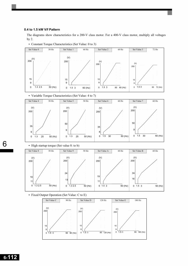
6-112
6
0.4 to 1.5 kW V/f PatternThe diagrams show characteristics for a 200-V class motor. For a 400-V class motor, multiply all voltagesby 2.
• Constant Torque Characteristics (Set Value: 0 to 3)
• Variable Torque Characteristics (Set Value: 4 to 7)
• High startup torque (Set value 8: to b)
• Fixed Output Operation (Set Value: C to E)
Set Value 0 50 Hz Set Value 1 60 Hz Set Value 2 60 Hz Set Value 3 72 Hz
Set Value 4 50 Hz Set Value 5 50 Hz Set Value 6 60 Hz Set Value 7 60 Hz
Set Value 8 50 Hz Set Value 9 50 Hz Set Value A 60 Hz Set Value B 60 Hz
Set Value C 90 Hz Set Value D 120 Hz Set Value E 180 Hz
1.3 2.5 1.5 1.5 3 1.5 3
1.3 1.3 1.5 1.5
1.3 2.5 1.3 2.5 1.5 1.5
1.5 1.5 1.5

6
2.2 to 45 kW V/f PatternThe diagrams show characteristics for a 200-V class motor. For a 400-V class motor, multiply all voltagesby 2.
• Constant Torque Characteristics (Set Value: 0 to 3)
• Variable Torque Characteristics (Set Value: 4 to 7)
• High Startup Torque (Set Value: 8 to b)
• Fixed Output Operation (Set Value: C to E)
Set Value 0 50 Hz Set Value 1 60 Hz Set Value 2 60 Hz Set Value 3 72 Hz
Set Value 4 50 Hz Set Value 5 50 Hz Set Value 6 60 Hz Set Value 7 60 Hz
Set Value 8 50 Hz Set Value 9 50 Hz Set Value A 60 Hz Set Value B 60 Hz
Set Value C 90 Hz Set Value D 120 Hz Set Value E 180 Hz
6-113

6-114
6
55 to 300 kW V/f PatternThe diagrams show characteristics for a 200-V class motor. For a 400-V class motor, multiply all voltagesby 2.
• Constant Torque Characteristics (Set Value: 0 to 3)
• Variable Torque Characteristics (Set Value: 4 to 7)
• High Startup Torque (Set Value: 8 to b)
• Fixed Output Operation (Set Value: C to E)
Set Value 0 50 Hz Set Value 1 60 Hz Set Value 2 60 Hz Set Value 3 72 Hz
Set Value 4 50 Hz Set Value 5 50 Hz Set Value 6 60 Hz Set Value 7 60 Hz
Set Value 8 50 Hz Set Value 9 50 Hz Set Value A 60 Hz Set Value B 60 Hz
Set Value C 90 Hz Set Value D 120 Hz Set Value E 180 Hz
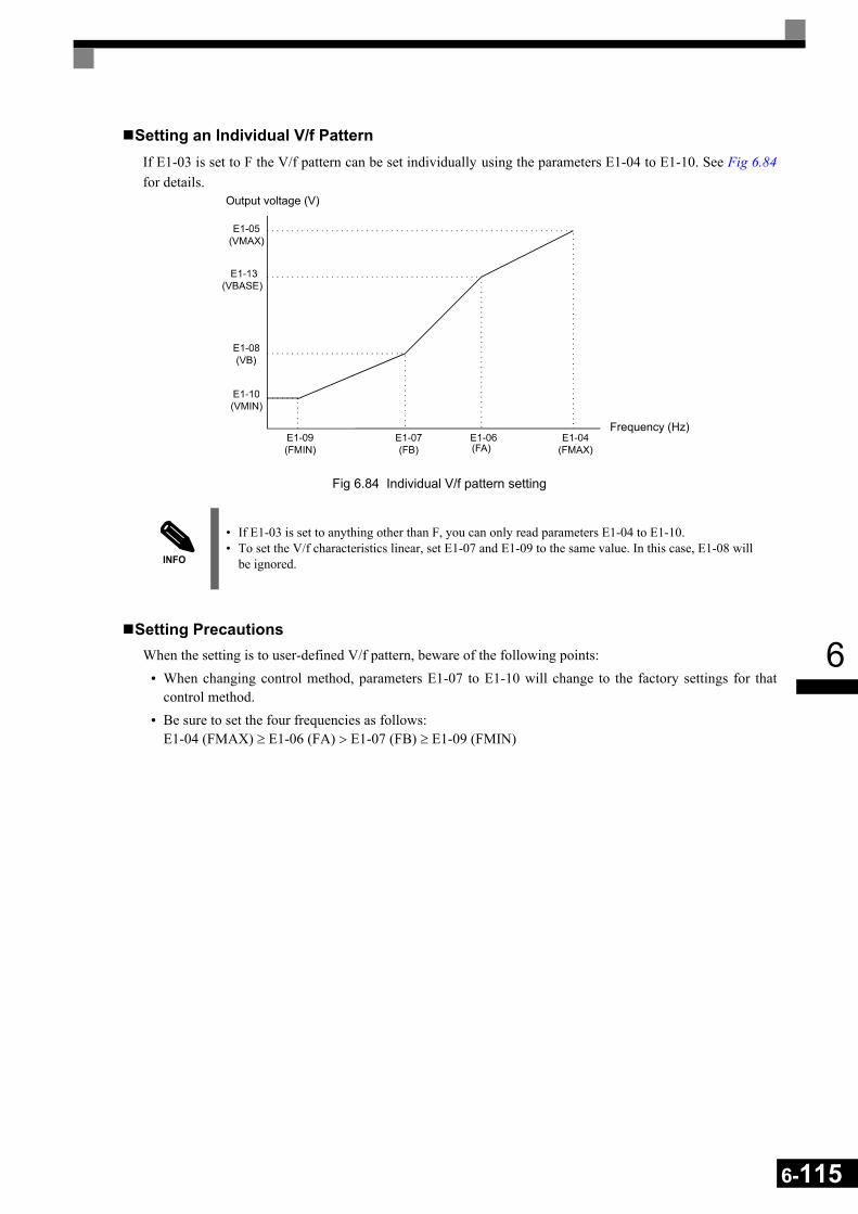
6
Setting an Individual V/f PatternIf E1-03 is set to F the V/f pattern can be set individually using the parameters E1-04 to E1-10. See Fig 6.84for details.
Fig 6.84 Individual V/f pattern setting
Setting PrecautionsWhen the setting is to user-defined V/f pattern, beware of the following points:
• When changing control method, parameters E1-07 to E1-10 will change to the factory settings for thatcontrol method.
• Be sure to set the four frequencies as follows:E1-04 (FMAX) ≥ E1-06 (FA) > E1-07 (FB) ≥ E1-09 (FMIN)
INFO
• If E1-03 is set to anything other than F, you can only read parameters E1-04 to E1-10. • To set the V/f characteristics linear, set E1-07 and E1-09 to the same value. In this case, E1-08 will
be ignored.
Output voltage (V)
Frequency (Hz)
6-115
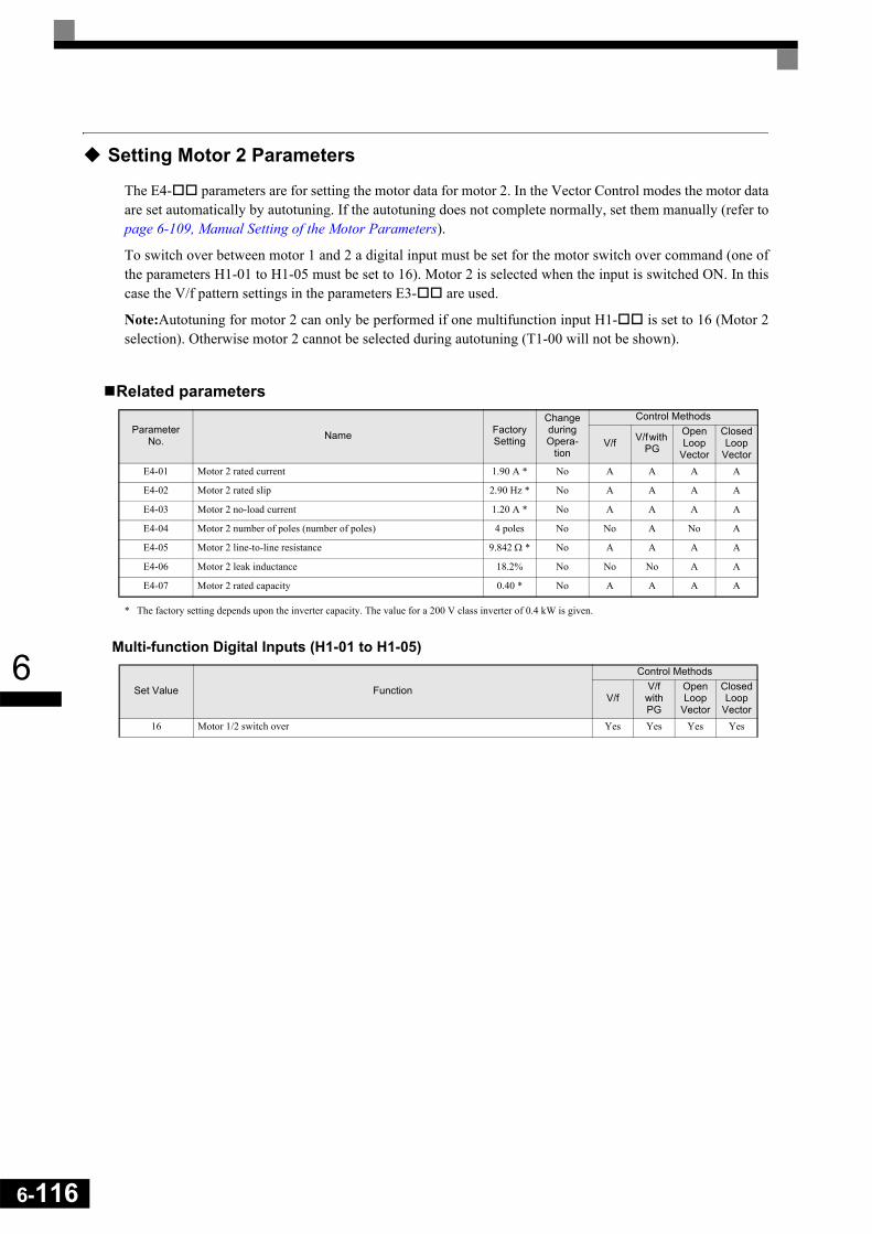
6-116
6
Setting Motor 2 Parameters
The E4- parameters are for setting the motor data for motor 2. In the Vector Control modes the motor dataare set automatically by autotuning. If the autotuning does not complete normally, set them manually (refer topage 6-109, Manual Setting of the Motor Parameters).
To switch over between motor 1 and 2 a digital input must be set for the motor switch over command (one ofthe parameters H1-01 to H1-05 must be set to 16). Motor 2 is selected when the input is switched ON. In thiscase the V/f pattern settings in the parameters E3- are used.
Note:Autotuning for motor 2 can only be performed if one multifunction input H1- is set to 16 (Motor 2selection). Otherwise motor 2 cannot be selected during autotuning (T1-00 will not be shown).
Related parameters
* The factory setting depends upon the inverter capacity. The value for a 200 V class inverter of 0.4 kW is given.
Multi-function Digital Inputs (H1-01 to H1-05)
Parameter No. Name Factory
Setting
Change during Opera-
tion
Control Methods
V/f V/f with PG
Open Loop
Vector
Closed Loop
VectorE4-01 Motor 2 rated current 1.90 A * No A A A A
E4-02 Motor 2 rated slip 2.90 Hz * No A A A A
E4-03 Motor 2 no-load current 1.20 A * No A A A A
E4-04 Motor 2 number of poles (number of poles) 4 poles No No A No A
E4-05 Motor 2 line-to-line resistance 9.842 Ω * No A A A A
E4-06 Motor 2 leak inductance 18.2% No No No A A
E4-07 Motor 2 rated capacity 0.40 * No A A A A
Set Value Function
Control Methods
V/fV/f with PG
Open Loop
Vector
Closed Loop
Vector16 Motor 1/2 switch over Yes Yes Yes Yes

6
Setting the V/f Pattern 2
Using the E3- parameters the V/f pattern for motor 2 can be set as needed.
It is not recommended to change the settings when the motor is used in open loop vector mode.
Related Parameters
* 1. These are values for a 200 V class inverter. Values for a 400 V class inverter are double* 2. The factory setting will change when the control method is changed. (Open Loop Vector control factory settings are given.)
Selecting the Motor 2 Control Method (E3-01) Using parameter E3-01 the control method for motor 2 can be selected.
• The setting of this parameter affects the autotuning function. If V/f or V/f with PG is selected the only pos-sible autotuning method will be stationary autotuning for line-to-line resistance.
Setting the V/f Pattern CharacteristicThe principle of setting the V/f pattern 2 is the same as for V/f pattern 1. Please refer to page 6-111, Setting V/f Pattern (E1-02) for details.
Note: The V/f pattern 2 settings are only used for motor 2, i.e. motor 2 has to be selected using a multi-function input (setting 16).
Parameter No. Name Factory
Setting
Change during Opera-
tion
Control Methods
V/f V/f with PG
Open Loop
Vector
Closed Loop
VectorE3-01 Motor 2 control method selection 0 No A A A A
E3-02 Motor 2 max. output frequency (FMAX) 50.0 Hz No A A A A
E3-03 Motor 2 max. output voltage (VMAX) 200.0 V *1 No A A A A
E3-04 Motor 2 max. voltage frequency (FA) 50.0 Hz No A A A A
E3-05 Motor 2 mid. output frequency 1 (FB) 3.0 Hz *2 No A A A No
E3-06 Motor 2 mid. output frequency voltage 1 (VB) 13.2 V *1*2
No A A A No
E3-07 Motor 2 min. output frequency (FMIN) 0.5 Hz *2 No A A A A
E3-08 Motor 2 min. output frequency voltage (VMIN) 2.4 V *1*2 No A A A No
6-117
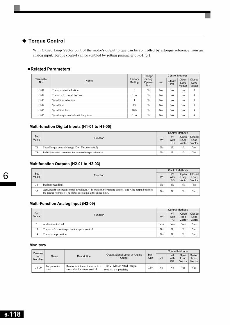
6-118
6
Torque Control
With Closed Loop Vector control the motor's output torque can be controlled by a torque reference from ananalog input. Torque control can be enabled by setting parameter d5-01 to 1.
Related Parameters
Multi-function Digital Inputs (H1-01 to H1-05)
Multifunction Outputs (H2-01 to H2-03)
Multi-Function Analog Input (H3-09)
Monitors
Parameter No. Name Factory
Setting
Change during Opera-
tion
Control Methods
V/f V/f with PG
Open Loop
Vector
Closed Loop
Vectord5-01 Torque control selection 0 No No No No A
d5-02 Torque reference delay time 0 ms No No No No A
d5-03 Speed limit selection 1 No No No No A
d5-04 Speed limit 0% No No No No A
d5-05 Speed limit bias 10% No No No No A
d5-06 Speed/torque control switching timer 0 ms No No No No A
Set Value Function
Control Methods
V/fV/f with PG
Open Loop
Vector
Closed Loop
Vector71 Speed/torque control change (ON: Torque control) No No No Yes
78 Polarity reverse command for external torque reference No No No Yes
Set Value Function
Control Methods
V/fV/f with PG
Open Loop
Vector
Closed Loop
Vector31 During speed limit No No No Yes
32 Activated if the speed control circuit (ASR) is operating for torque control. The ASR output becomes the torque reference. The motor is rotating at the speed limit. No No No Yes
Set Value Function
Control Methods
V/fV/f with PG
Open loop
Vector
Closed Loop
Vector0 Add to terminal A1 Yes Yes Yes Yes
13 Torque reference/torque limit at speed control No No No Yes
14 Torque compensation No No No Yes
Parame-ter
NumberName Description Output Signal Level at Analog
OutputMin. Unit
Control Methods
V/f V/f with PG
OpenLoop
Vector
Closed Loop
Vector
U1-09 Torque refer-ence
Monitor in internal torque refer-ence value for vector control.
10 V: Motor rated torque(0 to ± 10 V possible)
0.1% No No Yes Yes

6
Torque Control OperationIn torque control a torque value can be given as reference for the motor output. If the torque command and theload are not balanced, the motor accelerates or decelerates.
The speed limit circuit prevents the motor speed from rising above certain value set by an analog input orparameter d5-04. The speed limit function mainly consists of two parts, the priority circuit and the speedlimiter circuit.
The priority circuit selects between the torque reference value from the analog input or from the speed control-ler (ASR) output. If the output speed is below the speed limit, the analog input value is taken as torque refer-ence. Otherwise the ASR output value is taken as torque reference.
The speed limit circuit adds a speed suppressing torque to the torque output if the speed exceeds the speedlimit. Together with the priority circuit it prevents the output speed from exceeding the speed limit.
The torque control block diagram is shown in Fig 6.85.
Fig 6.85 Torque Control Block Diagram
Inputting Torque References and Torque Reference DirectionsThe torque reference can be input using an analog voltage or current signals. The torque reference input meth-ods are listed in the table below.
Torque Reference Input Method Reference Location Selection
Method Remarks
Voltage input (0 to 10 V) Analog input A2(Turn OFF pin 2 of SW1.)
H3-08 = 0H3-09 = 13
To switch the torque reference between positive and negative torque, use a digital input (H1- = 78).
Voltage input (-10 to +10 V)Analog input A2(Turn OFF pin 2 of SW1.)
H3-08 = 1H3-09 = 13
The torque reference direction is switched with the analog input voltage direction.
Current input (4 to 20 mA)Analog input A2(Turn ON pin 2 of SW1.)
H3-08 = 2H3-09 = 13
To switch the torque reference between positive and negative torque, use a digital input (H1- = 78).
Option Card (AI-14B) (0 to ±10 V) Channel 2
b1-01=1F2-01 = 0H3-08 = 1H3-09 = 13
Channel 1 of the AI-14B card replaces analog input A1
Torque compensationfrom analog input*
Torque reference fromanalog input A1
Speed limit fromanalog input A2
Speed limit inparameter d5-04
Speed feedback
Torque referencefilter time d5-02
Speed Controller(ASR)
Speed Limiter
PriorityCircuit
-+
Torquelimits
(L7- )
Internal torqueReference+
+
+
1
2d5-03
Speed limit biasd5-05
6-119

6-120
6
The direction of the torque output from the motor will be determined by the sign of the analog signal input ora digital input command. It does not depend on the direction of the run command. The direction of torque willbe as follows:
• Positive analog reference: Torque reference for forward motor rotation (counterclockwise as viewed fromthe motor output axis).
• Negative analog reference: Torque reference for reverse motor rotation (clockwise as viewed from themotor output axis).
Inputting the Speed Limit• The inputs methods for a speed limit are listed in the following table.
The direction in which speed is controlled is determined by the sign of the speed limit signal and the directionof the run command.
• Positive voltage applied: The speed in the forward direction will be limited for forward operation.• Negative voltage applied: The speed in the reverse direction will be limited for reverse operation.
If the direction of the motor rotation and the speed limit direction are not the same, the speed will be limited to 0.
Digital Output Functions (H2-01 to H2-03)
During Speed Limit (“31”)If a digital output is set for this function the output is activated, if the output speed is at the speed limit.
ASR active for Torque Control (“32”)Using this output function a digital output can be used to monitor the status of the speed limit function. Theoutput is switched:
• ON, if the torque reference is taken from the ASR output and the motor is operating at the speed limit• OFF, if the torque reference is taken from the analog input
Speed Limit Input Method Location of Refer-ence
Parameter Settings Remarks
Parameter setting Set in d5-04 d5-03 = 2 -
Voltage input (0 to +10 V) Analog input A1 b1-01 = 1H3-01 = 0
Use this setting if the speed limit has always to be positive.
Voltage input (-10 to +10 V) Analog input A1 b1-01 = 1H3-01 = 1
Use this setting when a speed limit for both directions has to be applied.
Current input (4 to 20 mA) Analog input A2
b1-01 = 1H3-08 = 2H3-09 = 13H3-13 = 1
Terminal A1 becomes the torque refer-ence value. Turn ON (I side) pin 2 of DIP switch S1 on the terminal board.
Option Card (AI-14B) (0 to ±10 V)
Channel 1 b1-01 = 1F2-01 = 0
Channel 1 of the AI-14B card replaces analog input A1
Channel 1 to 3 b1-01 = 3F2-01 = 1
The sum of the channels 1 to 3 is taken as speed limit.

6
Speed Limit Bias SettingThe speed limit bias can be set to limit both the forward and reverse speed to the same value. This differs fromthe operation of the speed limit setting. To use the speed limit bias, set d5-04 to 0 and set the bias in d5-05 asa percentage of the maximum output frequency.
To set 50% forward and reverse speed limits, set the speed limit setting to 0 (d5-03 = 2, d5-04 = 0, and d5-05= 50). The range of torque control will be from -50% to 50% of the maximum output speed.
When using both, the speed limit and the speed limit bias, the speed range of torque control will be the posi-tive and negative speed limits with the speed limit bias added to each.
ExampleThe speed range of torque control when the forward speed limit is 50% and the speed limit bias is 10% isshown in Fig 6.86. This figure does not take the priority circuit into account.
Fig 6.86 Speed Limit Bias Setting
Torque Control Operation ExamplesOperation examples will be described separately for winding operation, in which the speed and motor torqueare in the same directions, and rewinding operation, in which the speed and motor torque are in opposite direc-tions.
Winding OperationIn a winding operation, the line (speed) and torque generated by the motor are in the same direction. For thewinding operation, both the speed limit and the torque reference input are positive. The motor will acceleratewhen the torque reference input is larger than the load and will decelerate when it is smaller than the load. Ifthe motor turns faster than the speed limit, a negative compensation value is output from the speed limiter cir-cuit. When the speed then drops below the speed limit, a positive compensation value is output. The torquecompensation is proportional to the ASR proportional gain. When the sum of the torque reference and thetorque compensation output by the speed limiter is the same as the actual load, the motor will stop acceleratingand run at a constant speed.
Rewinding OperationIn a rewinding operation, the line (speed) and torque generated by the motor are in the opposite directions. (Inthis example, it is assumed that the line speed is positive and the torque reference input is negative.) For therewinding operation, the speed limit is positive and the torque reference input is negative. If the motor turnsfaster than the speed limit, a negative compensation value is output from the speed limiter circuit. If the motoris rotating in reverse, a positive compensation value is output. If the speed is 0 or is below the speed limit, a 0compensation value is output. In this way, the output from the speed limiter is used to maintain the motorspeed between 0 and the speed limit. When the sum of the torque reference and the torque compensation out-
Forwardoperation
Reverseoperation
Positive torque
Negative torque
Forward speed limit50%
Speed limit biasd5-05
6-121

6-122
6
put by the speed limiter is the same as the actual load, the motor will stop accelerating and run at a constantspeed.
Torque Reference Signal Adjustments
Torque Reference Delay Time (d5-02)The filter time constant in the torque reference section can be adjusted using parameter d5-02. This parameteris used to eliminate noise in the torque reference signal and adjust the responsiveness to the host controller.Increase the setting if oscillations occur during torque control.
Setting the Torque CompensationAn analog input can be used to apply a torque compensation (H3-09 = 14). When the amount of torque loss formechanical loss or other influences at the load is input to one of this terminal, it is added to the torque refer-ence to compensate the loss. The direction of torque will be as follows:
• Positive voltage (current): Torque compensation reference for forward motor rotation (counterclockwiseas viewed from the motor output axis).
• Negative voltage: Torque compensation reference for reverse motor rotation (clockwise as viewed fromthe motor output axis).
Since the polarity of the voltage input determines the direction, only forward torque compensation can beinput when the 0 to 10 V or 4 to 20 mA signal level has been selected. If a reverse torque compensation shallbe input, be sure to select the 0 to ±10 V signal level.
Speed/Torque Control Switching FunctionIt is possible to switch between speed control and torque control using one of the digital inputs (H1- = 71,Speed/Torque Control Change). Speed control is performed when the input is OFF and torque control is per-formed when the input is ON. The parameter d5-01 has to be set to 0.
Winding Operation Rewinding Operation
Configuration
Normal Rotation Direc-tion Forward Reverse Forward Reverse
Torque Reference Polar-ity (TREF)
Speed Limit Polarity (SLIM)
Generated Torque
M
n T
Line Direction n
T
M
Line Direction
Torque
Torquelimit
-(d5-05)
nLIM
Speed0
TREF
Torquelimit
nTorque
Torquelimit
(d5-05)
nLIM
Speed0
TREF
Torquelimit
n
Torque
Torquelimit
-(d5-05)
nLIM Speed0
TREF
Torquelimit
n
Torque
Torquelimit
(d5-05)
nLIM
Speed0
TREF
Torquelimit
n

6
Setting the Speed/Torque Control Switching Timer (d5-06)The delay between a change in the speed/torque control switching function input (ON to OFF or OFF to ON)and the corresponding change in the control mode can be set in parameter d5-06. During the timer delay, thevalue of the 2 analog inputs will retain the values they had when the ON/OFF status of speed/torque controlswitching signal was changed. Use this delay to complete any changes required in external signals.
Fig 6.87 shows an example of speed/torque control switching.
Fig 6.87 Speed/Torque Control Switching Time Chart
Application Precautions• The function of the torque reference input (A1 or A2) changes when the control mode is switched between
torque control and speed control.During speed control: The analog input terminal is used as the torque limit input.During torque control: The analog input terminal is used as the torque reference input.
• When the run command is turned OFF, the control method will be speed control. Even from the torquecontrol mode, the system will automatically change to speed control and decelerate to a stop when the runcommand turns OFF.
Speed/torque changesignal
Run command
Control mode
Terminal A1 input
Terminal A2 input
OPEN OPEN
CLOSED CLOSED
Stop
Run
Stop
Speed Speed Speed (decel to stop)
Speedreference
Speed limit Speed limit
Speedreference
Torque Torque
Torque limit Torque limit
Torquereference
Torquereference
1 2 3 4
6-123

6-124
6
Droop Control Function
Droop control is a function that allows to achieve a load sharing between two motors that drive a single load.The Droop Control function must be enabled at one inverter only. If by this inverter the torque rises, the speedis reduced and the other inverter takes over more load. Thereby the load is shared automatically to bothmotors.
Related Constants
Setting the Droop Control GainSet the Droop Control gain in parameter b7-01 to the amount of speed reduction when the maximum outputfrequency is input and the rated torque is generated (see Fig 6.88). b7-01 is set as percentage of the maximumoutput voltage.
Fig 6.88 Droop Control Gain
Droop Control can be disabled by setting the parameter b5-07 to 0.
Setting the Droop Control Delay TimeThe Droop Control delay time in parameter b7-02 is used to adjust the responsiveness of droop control.Increase this setting if oscillations or hunting occur.
Parameter No. Name Factory
Setting
Change during Opera-
tion
Control Methods
V/f V/f with PG
Open Loop
Vector
Closed Loop
Vectorb7-01 Droop Control gain 0.0 Yes No No No A
b7-02 Droop Control delay time 0.05 s No No No No A
b7-01Torque
SpeedSpeed reference0
100%

6
Zero-Servo Function
The Zero-Servo function holds the motor when the motor is stopped in a so called Zero-Servo status. Thismeans, that if the frequency reference falls below the Zero-Speed level (parameter b2-01) a position loop isactivated and the motor is kept at the position, even if a load is applied.
The zero-servo function must be enabled using a digital input, which is programmed for is set to Zero-Servocommand (H1- = 72).
The actual deviation of the rotor position from the zero position can be monitored using parameter U1-35. Theshown value must be divided by to the get the displacement in encoder pulses.
A digital output (H2- = 33) can be used to signalize the completion of a Zero-Servo command. The con-tact is closed as long as the actual rotor position is within the zero position E Zero-Servo completion width.
Related Constants
Multi-function Digital Inputs (H1-01 to H1-05)
Multifunction Outputs (H2-01 to H2-03)
Monitors
Parameter No. Name Factory
Setting
Change during Opera-
tion
Control Methods
V/f V/f with PG
Open Loop
Vector
Closed Loop
Vectorb2-01 Zero speed level (DC injection braking starting frequency) 0.5 Hz No A A A A
b9-01 Zero-servo gain 5 No No No No A
b9-02 Zero-Servo completion width 10 No No No No A
Set Value Function
Control Methods
V/fV/f with PG
Open Loop
Vector
Closed Loop
Vector72 Zero-servo command (ON: Zero-servo) No No No Yes
Set Value Function
Control Methods
V/fV/f with PG
Open Loop
Vector
Closed Loop
Vector
33 Zero-servo end ON: Current position is within zero-servo start position ± the zero-servo end width. No No No Yes
Parame-ter
NumberName Description Output Signal Level at Analog
OutputMin. Unit
Control Methods
V/f V/f with PG
OpenLoop
Vector
Closed Loop
Vector
U1-35Zero-servo movement pulses
Shows the number of PG pulses times 4 for the movement range when stopped at zero.
(Cannot be output.) 1 No No No A
6-125

6-126
6
Timing ChartAn example timing chart for the Zero-Servo function showing the input and output signals is given in the fig-ure below.
Fig 6.89 Time Chart for the Zero-Servo Function
Application Precautions• Be sure to leave the run command input activated. If the run command is turned OFF, the output will be
interrupted and the zero-servo function will become inactive.• The holding force of the Zero-Servo position loop can be adjusted in parameter b9-01. The holding force
will increase if the set value is increased. Oscillation and hunting may occur, if the setting is too large.Adjust b9-01 after adjusting the speed controller (ASR).
• The Zero-Servo detection width is set as the allowable displacement from the Zero-Servo start position.Set the b9-02 taking the number of displacement pulses from the PG multiplied by 4.
• The Zero-Servo completion signal will be turned OFF when the zero servo command is turned OFF.
IMPORTANT
Do not use the Zero-Servo for extended periods of time with 100% of torque. Inverter errors may result. If the Zero Servo function shall be used continuously, make sure that the output current dur-ing the servolock is 50% of the motor current or less.
Run command
OFFZero Servo Command
Frequency (speed)reference
Excitation levelb2-01
Motor speed
Zero Servo Endsignal
ON
ON
Zero-servo status
OFF

6
Kinetic Energy Buffering
The kinetic energy buffering function can be used to decelerate to stop after a sudden power loss using thekinetic energy of the rotating machine to maintain the DC bus voltage. Thereby an uncontrolled coasting of amachine can be prevented. The function can be activated using a multifunction input that i.e. can be operatedby a DC bus undervoltage alarm output or by a voltage drop relay. A wiring example is shown in Fig. 6.80.
Fig 6.90 Wiring Example for KEB function usage
Related Parameters
* The factory setting depends upon the inverter capacity. The value for a 200 V class inverter of 0.4 kW is given.
Setting the Momentary Power Loss Detection (L2-01)• L2-01 = 0
The inverter trips with undervoltage fault (UV1).• L2-01 =1
No UV1 is detected within the time which is set in parameter L2-02. If this time is exceeded and the powerhas not returned, an UV1 fault is output.
• No UV1 is detected. The inverter continues operation as long as the CPU is working.
To use the Kinetic Energy Buffering function in connection with the UV alarm output of the inverter, parame-ter L2-01 must be set to 1 or 2.
Setting the Undervoltage Level (L2-05)This parameter sets the voltage level for the DC bus at which a DC bus undervoltage (UV, UV1) is detected.
Normally there is no need to change this setting. If the UV detection is used for activating the Kinetic EnergyBuffering function, the UV detection level should be increased to the maximum to detect the UV as fast aspossible.
Parameter No. Name Factory
Setting
Change during Opera-
tion
Control Methods
V/f V/f with PG
Open Loop
Vector
Closed Loop
VectorC1-09 Fast stop time 10.0s No A A A A
L2-01 Momentary power loss detection 0 No A A A A
L2-05 Undervoltage detection level 190 V* No A A A A
L2-08 Frequency reduction gain at Kinetic Energy Buffering start. 100 No A A A A
L1L2L3
Voltage drop relay
Terminal S3 to S7
SN
Varispeed F7
H1- =66
toMotor
6-127
6-128
6
Adjusting the Kinetic Energy Buffering Deceleration Time (C1-09)The fast stop time set in parameter C1-09 is used to decelerate to stop when a Kinetic Energy Buffering com-mand is input.
To set up this parameter do the following:• Increase C1-09 until a UV1 fault is detected during deceleration. (If L2-01 is set to 2, no UV1 will be
detected, but the motor will start to coast when the DC bus voltage drops too much.) The highest settingvalue of C1-09, at which no UV1 is detected will be the maximum deceleration time.
• Decrease C1-09 until a DC bus overvoltage (OV) is detected. The lowest setting value of C1-09, at whichno OV is detected, will be the minimal deceleration time.
• Set a value for C1-09, that is somewhere in the middle between the maximum and the minimum decelera-tion time.
Adjusting the Frequency Reduction Gain at Kinetic Energy Buffering Start (L2-08)When the Kinetic Energy Buffering function is enabled, the output frequency is reduced for a certain fre-quency amount in order to prevent an UV1 fault. The amount of this frequency step can be set using parameterL2-08. It is set in percent of the slip frequency before the Kinetic Energy Buffering signal was input. Normallythere is no need to change this setting.
• Increase the setting if an undervoltage fault occurs right after Kinetic Energy Buffering start.• Decrease the setting if an overvoltage fault occurs right after Kinetic Energy Buffering start.
Multifunction Input Settings: H1-01 to H1-05 (Terminal S3-S7)
Kinetic Energy Buffering Command NC: “65”• Storing this setting for one of the parameters H1-01 to H1-05, the Kinetic Energy Buffering function can
be activated using a NC contact.
Kinetic Energy Buffering Command NO: “66”• Using this setting for one of the parameters H1-01 to H1-05, the Kinetic Energy Buffering function can be
activated using a NO contact.
High Slip Braking (HSB)
If the load inertia is large the high slip braking function can be used to shorten the deceleration time comparedto the normal deceleration time without using a braking option (braking resistor, braking resistor unit).
The function must be activated by a multifunction input. It is not comparable with the normal decelerationfunction. It does not use a ramp function.
HSB should not be used at normal operation instead of a deceleration ramp.

6
Related Parameters
Multi-function Digital Inputs (H1-01 to H1-05)
Adjusting the HSB Deceleration Frequency Width (N3-01)This parameter sets the step value that is used for lowering the output frequency to achieve a large negativeslip and thereby to brake the motor.
Normally no adjustments is necessary. Increase the value if a DC bus overvoltage faults occur.
Adjusting the HSB Current Limit (N3-02)The setting of parameter N3-02 limits the output current while high slip braking is active. The current limitaffects the achievable deceleration time.
The lower the current limit the longer is the deceleration time.
Setting the HSB Dwell Time at Stop (N3-03)At the end of a high slip braking the output frequency is held at the minimum output frequency for the time setin N3-03. Increase the time if the motor coasts after HSB.
Setting the HSB Overload Time (N3-04)N3-04 sets the HSB overload time. If the output frequency does not change for any reason although an HSBcommand is given, an OL7 fault will be displayed and the fault contact will operate.
Activating High Slip BrakingIf one of the multifunction inputs is set to “68” it can be used to activate the HSB function. The inverter willbrake the motor immediately after the HSB command was given. HSB cannot be stopped, i.e. normal inverteroperation cannot be resumed.
The HSB function is activated by a pulse signal, a continuous activating of the digital input is not necessary.
Parameter No. Name Factory
Setting
Change during Opera-
tion
Control Methods
V/f V/f with PG
Open Loop
Vector
Closed Loop
VectorN3-01 High-slip braking deceleration frequency width 5% No A A No No
N3-02 High-slip braking current limit 150% No A A No No
N3-03 High-slip braking stop dwell time 1.0 s No A A No No
N3-04 High-slip braking OL time 40 s No A A No No
Set Value Function
Control Methods
V/fV/f with PG
Open Loop
Vector
Closed Loop
Vector68 High Slip Braking command (ON: HSB activated) Yes Yes No No
6-129

6-130
6
Digital Operator Functions
Setting Digital Operator Functions
Related Parameters
* Depends on the inverter capacity
Monitor Selection (o1-01)Using parameter o1-01 the third monitor item that is displayed in drive mode can be selected. This functionhas no effect on the optional LCD-operator (JVOP-160).
Monitor Display when the Power Supply is Turned ON (o1-02)Using parameter o1-02 the monitor item (U1- ) that is to be displayed on the Digital Operator when thepower supply is turned ON can be selected.
Changing Frequency Reference and Display Units (o1-03)Set the Digital Operator frequency reference and display units using parameter o1-03. The setting in o1-03will affect the display units of the following monitor items:
• U1-01 (Frequency Reference)• U1-02 (Output Frequency)• U1-05 (Motor Speed)• U1-20 (Output Frequency after Soft Start)• d1-01 to d1-17 (Frequency references)
Parameter No. Name Factory
Setting
Change during Opera-
tion
Control Methods
V/f V/f with PG
Open Loop
Vector
Closed Loop
Vectoro1-01 Monitor selection 6 Yes A A A A
o1-02 Monitor selection after power up 1 Yes A A A A
o1-03 Frequency units of reference setting and monitor 0 No A A A A
o1-04 Setting unit for frequency reference related parameters 0 No No No No A
o1-05 LCD Display contrast 3 Yes A A A A
o2-01 LOCAL/REMOTE key enable/disable 1 No A A A A
o2-02 STOP key during control circuit terminal operation 1 No A A A A
o2-03 Inverter kVA selection 0* No A A A A
o2-04 User parameter initial value 0 No A A A A
o2-05 Frequency reference setting method selection 0 No A A A A
o2-06 Operation selection when digital operator is disconnected 0 No A A A A
o2-07 Cumulative operation time setting 0 No A A A A
o2-08 Cumulative operation time selection 0 No A A A A
o2-09 Initialize Mode 2 No A A A A
o2-10 Fan operation time setting 0 No A A A A
o2-12 Fault trace initialize 0 No A A A A
o2-13 kWh monitor initialize 0 No A A A A
6
Changing the Units for Frequency Parameters Related to V/f settings (o1-04)Using parameter o1-04 the unit for frequency parameters related to the V/f setting can be changed. If o1-04 isset to 0 it will be Hz. If o1-04 is set to 1 it will be rpm.
Changing the Display Contrast (o1-05)Using o1-05 the contrast of the LCD display on the digital operator can be raised or lowered. Lowering the o1-05 value will decrease the contrast and vice versa.
Disabling the LOCAL/REMOTE Key (o2-01)Set o2-01 to 0 to disable the LOCAL/REMOTE Key on the Digital Operator.
If the key is disabled, it cannot be used anymore to switch over the frequency reference source or the RUNcommand source between LOCAL and REMOTE.
Disabling the STOP Key (o2-02)This parameter is used to set whether the STOP key on the operator is active during remote control (b1-02 ≠ 0)or not.
If o2-02 is set to 1, a STOP command from the operators STOP key will be accepted. If o2-02 is set to 0 it willbe disregarded.
Initializing Changed Parameter Values (o2-03)You can save the current Inverter parameter setting values as user-set parameter initial values. Thereforeparameter o2-03 has to be set to 1.
To initialize the Inverter parameters using the user-set initial values in memory set parameter A1-03 to 1110.To clear the user-set initial values in memory, set o2-03 to 2.
Changing the Inverter Capacity Setting (o2-04)The inverter capacity setting can be set using parameter o2-04. Refer to page 5-72, Factory Settings thatChange with the Inverter Capacity (o2-04) to see parameters that depend on this setting.
Normally it not necessary to change this setting, unless the control card has been changed.
Setting the Frequency Reference using the UP and DOWN Keys without Using the Enter Key (o2-05)
This function is active when frequency references are input from the Digital Operator. When o2-05 is set to 1,you can increment and decrement the frequency reference using the UP and DOWN keys without using theEnter key.
Operation Selection when the Digital Operator is Disconnected (o2-06)This function selects the operation when the digital operator gets disconnected when a RUN command isactive.
If o2-06 is set to 0 the operation is continued.If o2-06 is set to 1 the output is switched off and the motor coasts to stop. The fault contact is operated. Whenthe operator is reconnected an OPR (Operator disconnected) is shown.
6-131
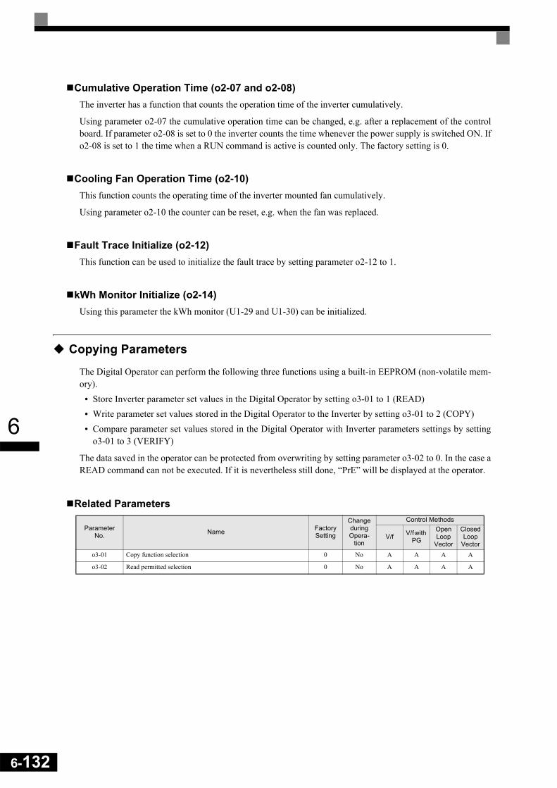
6-132
6
Cumulative Operation Time (o2-07 and o2-08)The inverter has a function that counts the operation time of the inverter cumulatively.
Using parameter o2-07 the cumulative operation time can be changed, e.g. after a replacement of the controlboard. If parameter o2-08 is set to 0 the inverter counts the time whenever the power supply is switched ON. Ifo2-08 is set to 1 the time when a RUN command is active is counted only. The factory setting is 0.
Cooling Fan Operation Time (o2-10)This function counts the operating time of the inverter mounted fan cumulatively.
Using parameter o2-10 the counter can be reset, e.g. when the fan was replaced.
Fault Trace Initialize (o2-12)This function can be used to initialize the fault trace by setting parameter o2-12 to 1.
kWh Monitor Initialize (o2-14)Using this parameter the kWh monitor (U1-29 and U1-30) can be initialized.
Copying Parameters
The Digital Operator can perform the following three functions using a built-in EEPROM (non-volatile mem-ory).
• Store Inverter parameter set values in the Digital Operator by setting o3-01 to 1 (READ)• Write parameter set values stored in the Digital Operator to the Inverter by setting o3-01 to 2 (COPY)• Compare parameter set values stored in the Digital Operator with Inverter parameters settings by setting
o3-01 to 3 (VERIFY)
The data saved in the operator can be protected from overwriting by setting parameter o3-02 to 0. In the case aREAD command can not be executed. If it is nevertheless still done, “PrE” will be displayed at the operator.
Related Parameters
Parameter No. Name Factory
Setting
Change during Opera-
tion
Control Methods
V/f V/f with PG
Open Loop
Vector
Closed Loop
Vectoro3-01 Copy function selection 0 No A A A A
o3-02 Read permitted selection 0 No A A A A

6
Storing Inverter set values in the Digital Operator (READ)To store Inverter set values in the Digital Operator use the following method.
If an error is displayed, press any key to cancel the error display and return to the o3-01 display. Refer to page 7-15, Digital Operator Copy Function Faults for corrective actions.
Step No. Explanation Digital Operator Display
1 Press the Menu Key and select advanced programming mode.
2 Press the DATA/ENTER Key.
3 Press the Increment and Decrement Key until parameter o3-01 is displayed (Copy Function Selection).
4 Press the DATA/ENTER Key and select the constants setting display.
5 Change the set value to 1 using the Increment Key.
6 Set the changed data using the DATA/ENTER Key. The READ function will start.
7 If the READ function ends normally, “End” is displayed on the Digital Oper-ator.
8 The display returns to o3-01 when a key is pressed.
** Main Menu **-ADV-
Programming
Initialization-ADV-
A1 - 00=1Select Language
COPY Function-ADV-
o3 - 01=0Copy Funtion Sel
Copy Function Sel-ADV-
o3-01= 0COPY SELECT
*0*
Copy Function Sel-ADV-
o3-01= 1 *0*
INV OP READ
READ-ADV-
INV OP READING
READ-ADV-
READ COMPLETE
Copy Function Sel-ADV-
o3 - 01=0COPY SELECT
*0*
6-133

6-134
6
Writing Parameter Set Values Stored in the Digital Operator to the Inverter (COPY)To write parameter set values stored in the Digital Operator to the Inverter, use the following method.
If an error is displayed, set the parameters again. Refer to page 7-15, Digital Operator Copy Function Faultsfor corrective actions.
Step No. Explanation Digital Operator Display
1 Press the MENU Key and select advanced programming mode.
2 Press the DATA/ENTER Key.
3 Press the Increment and Decrement Key until parameter o3-01 is displayed (Copy Function Selection).
4 Press the DATA/ENTER Key and select the constants setting display.
5 Change the set value to 2 using the Increment Key.
6 Set the changed data using the DATA/ENTER Key. The COPY function will start.
7 If the COPY function ends normally, “End” is displayed on the Digital Opera-tor.
8 The display returns to o3-01 when a key is pressed.
** Main Menu **-ADV-
Programming
Initialization-ADV-
A1 - 00 = 1Select Language
COPY Function-ADV-
o3 - 01 = 0Copy Funtion Sel
Copy Function Sel-ADV-
o3-01= 0COPY SELECT
*0*
Copy Function Sel-ADV-
o3-01= 2OP INV WRITE
*0*
COPY-ADV-
OP INV COPYING
COPY-ADV-
COPY COMPLETE
Copy Function Sel-ADV-
o3 - 01 =0COPY SELECT
*0*
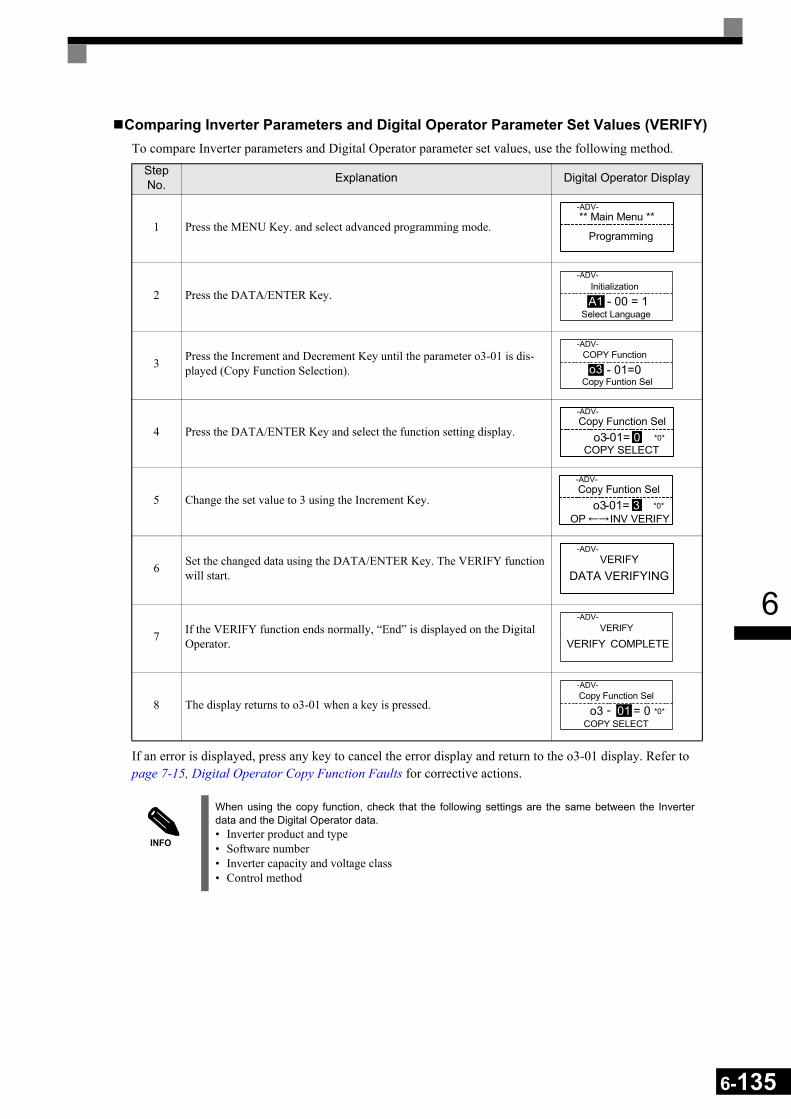
6
Comparing Inverter Parameters and Digital Operator Parameter Set Values (VERIFY)To compare Inverter parameters and Digital Operator parameter set values, use the following method.
If an error is displayed, press any key to cancel the error display and return to the o3-01 display. Refer to page 7-15, Digital Operator Copy Function Faults for corrective actions.
Step No. Explanation Digital Operator Display
1 Press the MENU Key. and select advanced programming mode.
2 Press the DATA/ENTER Key.
3 Press the Increment and Decrement Key until the parameter o3-01 is dis-played (Copy Function Selection).
4 Press the DATA/ENTER Key and select the function setting display.
5 Change the set value to 3 using the Increment Key.
6 Set the changed data using the DATA/ENTER Key. The VERIFY function will start.
7 If the VERIFY function ends normally, “End” is displayed on the Digital Operator.
8 The display returns to o3-01 when a key is pressed.
INFO
When using the copy function, check that the following settings are the same between the Inverterdata and the Digital Operator data.• Inverter product and type• Software number• Inverter capacity and voltage class• Control method
** Main Menu **-ADV-
Programming
Initialization-ADV-
A1 - 00 = 1Select Language
COPY Function-ADV-
o3 - 01=0Copy Funtion Sel
Copy Function Sel-ADV-
o3-01= 0COPY SELECT
*0*
Copy Funtion Sel-ADV-
o3-01= 3 *0*
OP INV VERIFY
VERIFY-ADV-
DATA VERIFYING
VERIFY-ADV-
VERIFY COMPLETE
Copy Function Sel-ADV-
o3 - 01 = 0COPY SELECT
*0*
6-135

6-136
6
Prohibiting Overwriting of Parameters
If A1-01 is set to 0, all parameters except A1-01 and A1-04 are write protected, U1- , U2- and U3- will be displayed. If A1-01 is set to 1, only the parameters A1-01, A1-04 and A2- can be read or
written, U1- , U2- and U3- will be displayed. All other parameters will not be displayed.
If you set one of the parameters H1-01 to H1-05 (digital input terminal S3 to S7 function selection) to 1B(write parameters permitted), parameters can be written from the digital operator when the terminal that hasbeen set is ON. When the set terminal is OFF, writing parameters other than the frequency reference is prohib-ited. However, the parameters can be read.
Related Parameters
Setting a Password
When a password is set in A1-05 and if the set values in A1-04 and A1-05 do not match, only the settings ofparameters A1-01 to A1-03, or A2-01 to A2-32 can be modified.
The setting of all parameters except A1-00 can be prohibited using the password function in combination withsetting parameter A1-01 to 0 (Monitor only).
Related Parameters
Setting a PasswordThe password can be set in parameter A1-05. Normally A1-05 is not displayed. To display and modify A1-05the MENU and Reset key must be pressed together in the A1-04 display.
Parameter No. Name Factory
Setting
Change during Opera-
tion
Control Methods
V/f V/f with PG
Open Loop
Vector
Closed Loop
VectorA1-01 Parameter access level 2 Yes A A A A
Parameter No. Name Factory
Setting
Change during Opera-
tion
Control Methods
V/f V/f with PG
Open Loop
Vector
Closed Loop
VectorA1-01 Parameter access level 2 No A A A A
A1-04 Password 0 No A A A A
A1-05 Password setting 0 No A A A A

6
Displaying User-set Parameters Only
The A2 parameters (user-set parameters) and A1-01 (parameter access level) can be used to establish a param-eter set that contains only the most important parameters.
Set the number of the parameter to which you want to refer in A2-01 to A2-32, and then set A1-01 to 1. Usingthe advanced programming mode you can read and modify A1-01 to A1-03 and the parameters set in A2-01 toA2-32 only.
Related Parameters
Parameter No. Name Factory
Setting
Change during Opera-
tion
Control Methods
V/f V/f with PG
Open Loop
Vector
Closed Loop
VectorA2-01
toA2-32
User setting parameters - No A A A A
6-137

6-138
6
Option Cards
Using PG Feedback Option Cards
To get a more precise speed control the inverter can be equipped with a PG option card to connect a pulse gen-erator. Two different PG cards can be used, the PG-B2 and the PG-X2. Refer to page 2-28, Option Card Mod-els and Specifications to see details.
Related Parameters
Using PG Speed Control CardThere are two types of PG Speed Control Card that can be used in V/f control with PG and Closed Loop Vec-tor control:
• PG-B2: A/B-phase pulse input, compatible with complementary outputs.• PG-X2: A/B/Z-phase pulse input, compatible with line drivers (RS-422).
For the mounting instructions, specifications and connection diagrams refer to page 2-28, Installing and Wir-ing Option Cards.
Setting Number of PG Pulses (F1-01)Set the number of PG (Pulse Generator/Encoder) pulses in pulses per revolution.
Parameter No. Name Factory
Setting
Change during Opera-
tion
Control Methods
V/f V/f with PG
Open Loop
Vector
Closed Loop
VectorF1-01 PG constant 1024 No No Q Q Q
F1-02 Operation selection at PG open circuit (PGO) 1 No No A No A
F1-03 Operation selection at overspeed (OS) 1 No No A No A
F1-04 Operation selection at deviation (DEV) 3 No No A No A
F1-05 PG rotation 0 No No A A A
F1-06 PG division rate (PG pulse monitor) 1 No No A A A
F1-07 Integral value during accel/decel enable/disable 0 No No A No A
F1-08 Overspeed (OS) detection level 115% No No A No A
F1-09 Overspeed detection delay time (OS) 1.0 s No No A No A
F1-10 Excessive speed deviation (DEV) detection level 10% No No A No A
F1-11 Excessive speed deviation detection delay time (DEV) 0.5 s No No A No A
F1-12 Number of PG gear teeth 1 0 No No A No A
F1-13 Number of PG gear teeth 2 0 No No A No A
F1-14 PG open-circuit detection delay time 2.0 s No No A No A
IMPORTANT
If Open Loop Vector control is used and a PG card is installed, the speed detected by the PG card is dis-played in the monitor parameter U1-05. Therefore the PG constant has to be set in parameter F1-01. The direction of the speed detection can be changed by parameter F1-05.To change the U1-05 value to the internally calculated value remove the PG card.

6
Suit the PG Rotation Direction and Motor Rotation Direction (F1-05)Parameter F1-05 suits the PG rotation direction to the motor rotation direction. If the motor is rotating for-wards, set whether it is A-phase leads or B-phase leads.
Generally, the A-phase leads when the rotation direction is counter-clockwise (CCW) seen from the shaft side(FWD command is input).
Setting Number of Gear Teeth Between PG and Motor (F1-12 and F1-13)If there are gears between the motor and PG, the gear ratio can be set using F1-12 and F1-13.
When the number of gear teeth has been set, the number of motor rotations within the Inverter is calculatedusing the following formula.
No. of motor rotations (r/min.) = No. of input pulses from PG × 60 / F1-01 × F1-13 (No. of gear teeth on PGside) / F1-12 (No. of gear teeth on motor side)
Integral Operation During Acceleration and Deceleration (F1-07)You can select whether to enable or disable integral operation during acceleration and deceleration.
To make the motor speed matching the frequency reference as closely as possible even during accelerationand deceleration, set F1-07 to 1. Refer also to page 6-36, Automatic Speed Regulator (ASR).
IMPORTANT
If F1-07 is set to 1, overshoot or undershoot may occur easily immediately after acceleration and decel-eration. To minimize the possibility of overshoot or undershoot occurring, set F1-07 to 0.
Inverter
Forwardcommand
Motor PG (encoder)
Pulse outputA-phase leads when set value = 0 B-phase leads when set value = 1
A-phase A-phase
B-phase B-phase
Example: Forward rotation of standard motor (PG)
Forwardcommand
Motor output axis rotatescounter-clockwise during In-verter forward command.
Rotation(CCW)
A-phase
B-phase
With the used PG the A-phase leads (CCW) when motor rotation is forward.
6-139
6-140
6
Setting PG Pulse Monitor Output Dividing Ratio (F1-06)This function is enabled only when using PG speed control card PG-B2. Set the dividing ratio for the PG pulsemonitor output. The set value is expressed as n for the higher place digit, and m for the two lower place digits.The dividing ratio is calculated as follows:
The dividing ratio can be set within the following range: 1/32 ≤ F1-06 ≤ 1. For example, if the dividing ratio is1/2 (set value 2), half of the number of pulses from the PG are output at the pulse monitor.
Detecting PG Open Circuit (F1-02 and F1-14)Parameter F1-02 selects the stopping method when a PG disconnection is detected.
PG open (PGO) is only detected when the inverter is running at least with a frequency reference higher than1% of the maximum output frequency or above the minimum frequency (E1-09) and the PG feedback signal ismissing for the time set in F1-14 or longer.
Detecting Motor Overspeed (F1-03, F1-08 and F1-09)An overspeed (OS) is detected when the motor speed continues to exceed the set frequency value in F1-08 fora time longer than set in F1-09. After detecting an overspeed (OS), the Inverter stops according to the settingin F1-03.
Detecting Speed Difference between the Motor and Speed Reference (F1-04, F1-10 and F1-11)
Speed deviation is detected when the speed deviation (i.e., the difference between the speed reference and theactual motor speed) is too large. Speed deviation (DEV) is detected only after a speed agreement (speed refer-ence and actual motor speed are within the setting range of L4-02) and if a speed deviation higher than the setvalue in F1-10 continues for longer than the time set in F1-11. After a speed deviation is detected, the Inverterstops according to the setting in F1-04.
Dividing ratio = (1 + n)/m (Setting range) n: 0 or 1, m: 1 to 32
F1-06 = n m

6
Analog Reference Cards
When using a AI-14B or A1-14U analog reference card, set parameter b1-01 (Reference selection) to 3(Option Card).
The AI-14B provides 3 bi-polar input channels with 14-bit (plus sign) A/D conversion.
If b1-01 is set to 1 and F2-01 is set to 0, the channel 1 and 2 replace the analog inputs A1 and A2. A1 becomesthe frequency reference input and the function of A2 can be selected using parameter H3-09. In this case nodigital input can be set for the Option/Inverter selection function (H1- = 2).
If b1-02 is set to 3 and F2-01 is set to 1, the sum of three input channels becomes the frequency referencevalue.
The AI-14U provides 2 unipolar inputs channels with 14-bit A/D conversion. Channel 1 is a voltage input andchannel 2 is a current input. The sum of the channels 1 and 2 is the frequency reference. F2-01 does not needto be set for the AI-14U option card.
Related Parameters
Digital Reference Cards
When using a DI-08 or DI-16H2 Digital Reference Card, set b1-01 (Reference selection) to 3 (Option Card).
The DI-16H2 can be used to set a frequency using a 16-bit digital reference.
The DI-08 can be used to set a frequency using a 8-bit digital reference.
Related Parameters
Parameter No. Name Factory
Setting
Change during Opera-
tion
Control Methods
V/f V/f with PG
Open Loop
Vector
Closed Loop
Vectorb1-01 Frequency reference source selection 1 No Q Q Q Q
F2-01 Bi-polar or uni-polar input selection 0 No A A A A
Parameter No. Name Factory
Setting
Change during Opera-
tion
Control Methods
V/f V/f with PG
Open Loop
Vector
Closed Loop
VectorF3-01 Digital input selection 0 No A A A A
o1-03 Frequency units of reference setting and monitor 0 No A A A A
6-141

6-142
6
Selecting Input Terminal Functions for the DI-16H2 Digital Reference CardThe frequency reference from the DI-16H2 Card is determined by the setting of F3-01 and the 12/16-bitswitch on the Option card. The possible settings are listed in the table below.
Application Precautions• The maximum frequency (100% speed) reference will be used when the binary input is set (setting: 6 or 7)
and all bits are 1.• Setting F3-01 to 6 is valid only when the D1-16H2 is used. Using this setting a frequency from 0.00 to
399.8 Hz can be set in BCD. The sign bit is used as a data bit, i.e. only positive data can be set. Also, thedigit starts from 0, i.e. the minimum setting is 0.02 Hz.
Terminal Pin No.
12-bit Binary with Sign
16-bit Binary with Sign
3-digit BCD with Sign
4-digit BCD with Sign
5-digit BCD with-out Sign
F3-01 = 7S1: 12 bit
F3-01 = 7S1: 16 bit
F3-01 = 0 to 5S1: 12 bit
F3-01 = 0 to 5S1: 16 bit
F3-01 = 6S1: 16 bit
TC1
1 Bit 0 (20) Bit 0 (20) 1
BDC digit 1(0 to 9)
1
BDC digit 1(0 to 9)
2BDC digit 1
(2 to 9)2 Bit 1 (21) Bit 1 (21) 2 2 4
3 Bit 2 (22) Bit 2 (22) 4 4 8
4 Bit 3 (23) Bit 3 (23) 8 8 1
BDC digit 2(0 to 9)
5 Bit 4 (24) Bit 4 (24) 1
BDC digit 2(0 to 9)
1
BDC digit 2(0 to 9)
2
6 Bit 5 (25) Bit 5 (25) 2 2 4
7 Bit 6 (26) Bit 6 (26) 4 4 8
8 Bit 7 (27) Bit 7 (27) 8 8 1
BDC digit 3(0 to 9)
9 Bit 8 (28) Bit 8 (28) 1
BDC digit 3(0 to 9)
1
BDC digit 3(0 to 9)
2
10 Bit 9 (29) Bit 9 (29) 2 2 4
TC2
1 Bit A (210) Bit A (210) 4 4 8
2 Bit B (211) Bit B (211) 8 8 1
BDC digit 4(0 to 9)
3 - Bit C (212) - 1
BDC digit 4(0 to 9)
2
4 - Bit D (213) - 2 4
5 - Bit E (214) - 4 8
6 - Bit F (215) - 8 1 BDC digit 5(0 to 3)7 Sign signal (0: Forward, 1: Reverse) 2
8 SET (read) signal (1: Read)9 Input signal common (0 V)
TC3 Shield wire connection terminal

6
Selecting the Input Terminal Function for a DI-08 Digital Reference CardThe frequency reference from a DI-08 Card is determined by the setting of F3-01, as shown in the followingtable.
Application PrecautionsThe DI-08 will not function if F3-01 is set to 6.
Terminal Pin No.8-bit Binary with Sign 2-digit BCD with Sign
F3-01 = 7 F3-01 = 0 to 5
TC
1 Bit 0 (20) 1
BDC digit 1(0 to 9)
2 Bit 1 (21) 2
3 Bit 2 (22) 4
4 Bit 3 (23) 8
5 Bit 4 (24) 1
BDC digit 2(0 to 15)
6 Bit 5 (25) 2
7 Bit 6 (26) 4
8 Bit 7 (27) 89 Sign signal10 SET (read) signal11 Reference common signal (0 V)
6-143
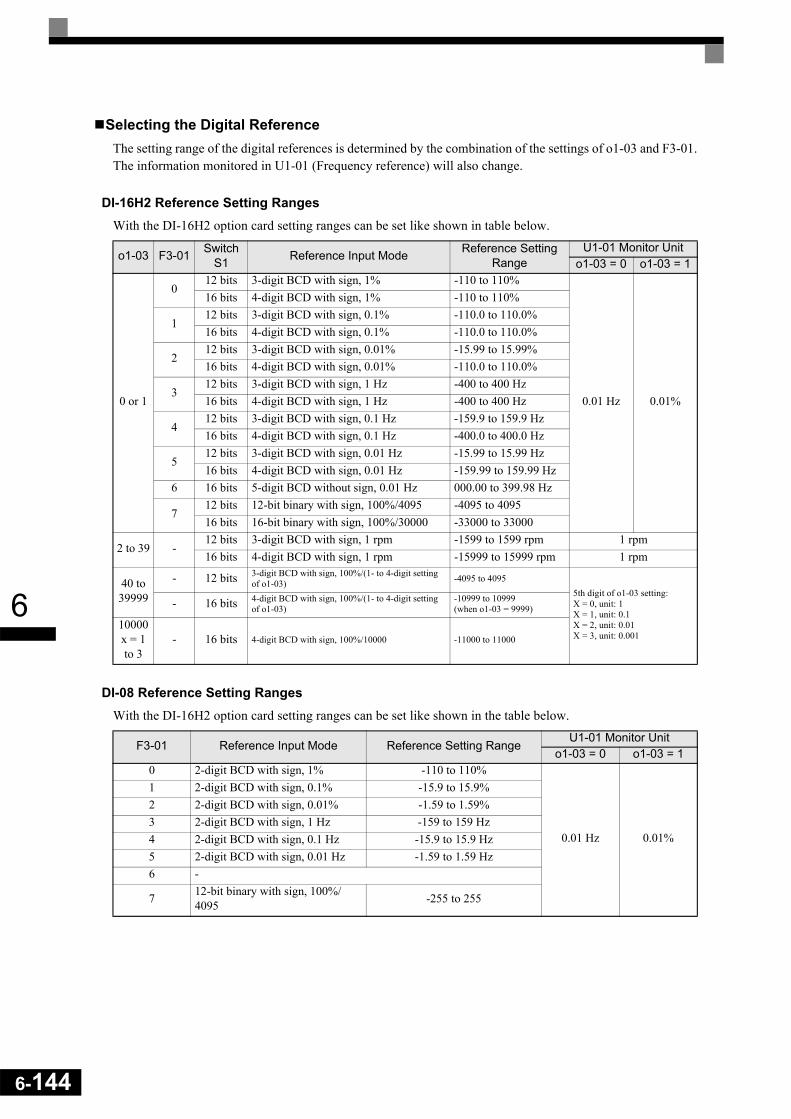
6-144
6
Selecting the Digital ReferenceThe setting range of the digital references is determined by the combination of the settings of o1-03 and F3-01.The information monitored in U1-01 (Frequency reference) will also change.
DI-16H2 Reference Setting Ranges With the DI-16H2 option card setting ranges can be set like shown in table below.
DI-08 Reference Setting RangesWith the DI-16H2 option card setting ranges can be set like shown in the table below.
o1-03 F3-01 Switch S1 Reference Input Mode Reference Setting
RangeU1-01 Monitor Unit
o1-03 = 0 o1-03 = 1
0 or 1
012 bits 3-digit BCD with sign, 1% -110 to 110%
0.01 Hz 0.01%
16 bits 4-digit BCD with sign, 1% -110 to 110%
112 bits 3-digit BCD with sign, 0.1% -110.0 to 110.0%16 bits 4-digit BCD with sign, 0.1% -110.0 to 110.0%
212 bits 3-digit BCD with sign, 0.01% -15.99 to 15.99%16 bits 4-digit BCD with sign, 0.01% -110.0 to 110.0%
312 bits 3-digit BCD with sign, 1 Hz -400 to 400 Hz16 bits 4-digit BCD with sign, 1 Hz -400 to 400 Hz
412 bits 3-digit BCD with sign, 0.1 Hz -159.9 to 159.9 Hz16 bits 4-digit BCD with sign, 0.1 Hz -400.0 to 400.0 Hz
512 bits 3-digit BCD with sign, 0.01 Hz -15.99 to 15.99 Hz16 bits 4-digit BCD with sign, 0.01 Hz -159.99 to 159.99 Hz
6 16 bits 5-digit BCD without sign, 0.01 Hz 000.00 to 399.98 Hz
712 bits 12-bit binary with sign, 100%/4095 -4095 to 409516 bits 16-bit binary with sign, 100%/30000 -33000 to 33000
2 to 39 -12 bits 3-digit BCD with sign, 1 rpm -1599 to 1599 rpm 1 rpm16 bits 4-digit BCD with sign, 1 rpm -15999 to 15999 rpm 1 rpm
40 to 39999
- 12 bits 3-digit BCD with sign, 100%/(1- to 4-digit setting of o1-03) -4095 to 4095
5th digit of o1-03 setting:X = 0, unit: 1X = 1, unit: 0.1X = 2, unit: 0.01X = 3, unit: 0.001
- 16 bits 4-digit BCD with sign, 100%/(1- to 4-digit setting of o1-03)
-10999 to 10999(when o1-03 = 9999)
10000x = 1 to 3
- 16 bits 4-digit BCD with sign, 100%/10000 -11000 to 11000
F3-01 Reference Input Mode Reference Setting RangeU1-01 Monitor Unit
o1-03 = 0 o1-03 = 10 2-digit BCD with sign, 1% -110 to 110%
0.01 Hz 0.01%
1 2-digit BCD with sign, 0.1% -15.9 to 15.9%2 2-digit BCD with sign, 0.01% -1.59 to 1.59%3 2-digit BCD with sign, 1 Hz -159 to 159 Hz4 2-digit BCD with sign, 0.1 Hz -15.9 to 15.9 Hz5 2-digit BCD with sign, 0.01 Hz -1.59 to 1.59 Hz6 -
7 12-bit binary with sign, 100%/4095 -255 to 255

7 Troubleshooting
This chapter describes the fault displays and countermeasures for Inverter and motor problems.
Protective and Diagnostic Functions......................................7-2 Troubleshooting ...................................................................7-17

7-2
7
Protective and Diagnostic Functions
This section describes the fault and alarm functions of the Inverter. These functions include fault detection,alarm detection, operator programming error detection and auto-tuning error detection.
Fault Detection
When the Inverter detects a fault, the fault contact output operates and the Inverter output is switched OFFcausing the motor to coast to stop. (The stopping method can be selected for some faults.) A fault code is dis-played on the Digital Operator.
When a fault has occurred refer to the following table to identify the fault and to correct the causes.
Use one of the following methods to reset the fault before restarting the Inverter:• Set a multi-function contact input (H1-01 to H1-05) to 14 (Fault Reset) and turn ON the error reset signal.• Press the RESET key on the Digital Operator.• Turn the main circuit power supply OFF and then ON again.
To reset a fault it is necessary to remove the cause of the fault and the RUN signal. Only then a Reset signal isaccepted.
Table 7.1 Fault Detection
Display Meaning Probable Causes Corrective Actions
GFGround Fault
Ground FaultThe ground current at the Inverter output exceeded 50% of the Inverter rated output current and L8-09=1 (Enabled).
One Inverter output was shorted to ground and/or a DCCT is defective.
Remove the motor and run the Inverter without the motor.
Check the motor for a phase to ground short.
Check the output current with a clampmeter to verify the DCCT reading.
OCOver Current
OvercurrentThe Inverter’s output current exceeded the overcurrent detec-tion level.
Shorted Inverter output phase-to-phase, shorted motor, locked rotor, load too heavy, accel/decel time too short, contactor on the Inverter output has opened or closed, a special motor or a motor with a rated current larger than the Inverter’s output current is used.
Remove the motor and run the Inverter without the motor.
Check the motor for a phase-to-phase short.
Verify the accel/decel times (C1- ).
Check the Inverter for a phase-to-phase short at the output.
PUFDC Bus Fuse Open
DC Bus FuseThe fuse in the main circuit is open.Warning: Never run the Inverter after replacing the DC bus fuse without checking for shorted components.
Shorted output or terminals or damaged IGBT’s.
Check the motor and the motor cables for short circuits or insulation failures (phase-to-phase).
Replace the inverter after cor-recting the fault.
OVDC Bus Overvolt
DC Bus OvervoltageThe DC bus voltage has exceeded the overvoltage detection level.Default detection levels are: 200 V class: 410 VDC400 V class: 820 VDC
The deceleration time is set too short and the regenerative energy from the motor is too large.
Increase the deceleration time (C1-02/04/06/08) or connect a braking option.
The power supply voltage is too high.
Check the power supply and decrease the voltage to meet the inverter’s specifications.
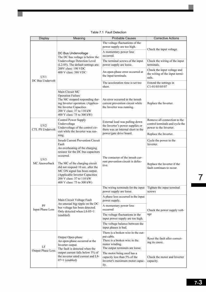
7
UV1DC Bus Undervolt
DC Bus UndervoltageThe DC bus voltage is below the Undervoltage Detection Level (L2-05). The default settings are:200V class: 190 VDC400 V class: 380 VDC
The voltage fluctuations of the power supply are too high.
Check the input voltage. A momentary power loss occurred.
The terminal screws of the input power supply are loose.
Check the wiring of the input terminals.
An open-phase error occurred at the input terminals.
Check the input voltage and the wiring of the input termi-nals.
The acceleration time is set too short.
Extend the settings inC1-01/03/05/07
Main Circuit MC Operation FailureThe MC stopped responding dur-ing Inverter operation. (Applica-ble Inverter Capacities200 V class: 37 to 110 kW400 V class: 75 to 300 kW)
An error occurred in the inrush current prevention circuit while the Inverter was running.
Replace the Inverter.
UV2CTL PS Undervolt
Control Power Supply UndervoltageUndervoltage of the control cir-cuit while the Inverter was run-ning.
External load was pulling down the Inverter’s power supplies or there was an internal short in the power/gate drive board.
Remove all connection to the control terminals and cycle the power to the Inverter.
Replace the Inverter.
UV3MC Answerback
Inrush Current Prevention Circuit FaultAn overheating of the charging resistor for the DC bus capacitors occurred.
The MC of the charging circuit did not respond 10 sec. after the MC ON signal has been output. (Applicable Inverter Capacities200 V class: 37 to 110 kW400 V class: 75 to 300 kW)
The contactor of the inrush cur-rent prevention circuit is defec-tive.
Cycle the power to the Inverter.
Replace the Inverter if the fault continues to occur.
PFInput Phase Loss
Main Circuit Voltage FaultAn unusual big ripple on the DC bus voltage has been detected. Only detected when L8-05=1 (enabled)
The wiring terminals for the input power supply are loose.
Tighten the input terminal screws
A phase loss occurred in the input power supply.
Check the power supply volt-age
A momentary power loss occurred
The voltage fluctuations in the input power supply are too high.
The voltage balance between the input phases is bad.
LFOutput Phase Loss
Output Open-phaseAn open-phase occurred at the Inverter output.The fault is detected when the output current falls below 5% of the inverter rated current and L8-07=1 (enabled)
There is a broken wire in the out-put cable.There is a broken wire in the motor winding.The output terminals are loose.
Reset the fault after correct-ing its cause.
The motor being used has a capacity less than 5% of the Inverter's maximum motor capac-ity.
Check the motor and Inverter capacity.
Table 7.1 Fault Detection
Display Meaning Probable Causes Corrective Actions
7-3

7-4
7
OH Heatsink Overtemp
Heatsink OverheatThe temperature of the Inverter's cooling fin exceeded the setting in L8-02 and L8-03 = 0 to 2.
The ambient temperature is too high.
Check for dirt build-up on the fans or heatsink.
There is a heat source nearby. Reduce the ambient tempera-ture around the drive.
The Inverter's cooling fan(s) stopped.
Replace the cooling fan(s).Inverter's Cooling Fan Stopped
The Inverter's internal cooling fan has stopped (18.5 kW and larger).
OH1Heatsink Max
Temp
Heatsink OverheatThe temperature of the Inverter’s heatsink exceeded 105 °C.
The ambient temperature is too high.
Check for dirt build-up on the fans or heatsink.
There is a heat source nearby. Reduce the ambient tempera-ture around the drive.
The Inverter’s cooling fan(s) stopped.
Replace the cooling fan(s).Inverter’s Cooling Fan Stopped
The Inverter’s internal cooling fan has stopped(18.5 kW and larger).
OH3Motor Overheat 1
Motor OverheatingDetected when the level at A2, programmed for motor tempera-ture (Thermistor input, H3-09=E), exceeds 1.17 V for the time L1-05 and L1-03 = 0 to 2.
Overheating of the motor was measured by the motor thermistor.
Recheck the cycle time and the size of the load.
Recheck the accel and decel times (C1- ).
Recheck the V/f pattern (E1- ).
Recheck the motor rated cur-rent value (E2-01).
OH4Motor Overheat 2
Motor OverheatingDetected when the level at A2, programmed for motor tempera-ture (Thermistor input, H3-09=E), exceeds 2.34 V for the time L1-05 and L1-03 = 0 to 2.
Overheating of the motor was measured by the motor thermistor.
Recheck the cycle time and the size of the load.
Recheck the accel and decel times (C1- ).
Recheck the V/f pattern (E1- ).
Recheck the motor rated cur-rent value (E2-01).
RHDynBrk Transistr
Dynamic Braking ResistorThe protection of the heatsink mounted resistor is activated when L8-01=1. This fault is only applicable when using the 3% duty cycle resistor, which is mounted on the Inverter’s heatsink. For all other resistors, set L8-01=0.
Overhauling load, extended dynamic braking duty cycle, defective dynamic braking resis-tor.
Verify dynamic braking duty cycle (load, decel times, motor speed).
Monitor DC bus voltage.
Replace dynamic braking resistor.
RRDynBrk Transistr
Dynamic Braking TransistorThe built-in dynamic braking transistor failed.
Defective or failed dynamic brak-ing resistor caused braking tran-sistor damage.
Cycle power to the Inverter.
Replace the Inverter.
Table 7.1 Fault Detection
Display Meaning Probable Causes Corrective Actions
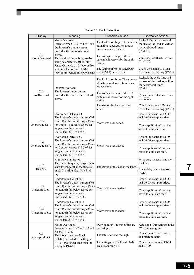
7
OL1Motor Overload
Motor OverloadDetected when L1-01 = 1 to 3 and the Inverter’s output current exceeded the motor overload curve. The overload curve is adjustable using parameter E2-01 (Motor Rated Current), L1-01(Motor Pro-tection Selection) and L2-02 (Motor Protection Time Constant)
The load is too large. The acceler-ation time, deceleration time or cycle time are too short.
Recheck the cycle time and the size of the load as well as the accel/decel times (C1- ).
The voltage settings of the V/f pattern is incorrect for the appli-cation.
Check the V/f characteristics (E1- ).
The setting of Motor Rated Cur-rent (E2-01) is incorrect.
Check the setting of Motor Rated Current Setting (E2-01).
OL2Inv Overload
Inverter OverloadThe Inverter output current exceeded the Inverter’s overload curve.
The load is too large. The acceler-ation time or deceleration times are too short.
Recheck the cycle time and the size of the load as well as the accel/decel times(C1- ).
The voltage settings of the V/f pattern is incorrect for the appli-cation.
Check the V/f characteristics (E1- ).
The size of the Inverter is too small.
Check the setting of Motor Rated Current Setting (E2-01).
OL3Overtorque Det 1
Overtorque Detection 1The Inverter’s output current (V/f control) or the output torque (Vec-tor Control) exceeded L6-02 for longer then the time set in L6-03 and L6-01 = 3 or 4.
Motor was overloaded.
Ensure the values in L6-02 and L6-03 are appropriate.
Check application/machine status to eliminate fault.
OL4Overtorque Det 2
Overtorque Detection 2The Inverter’s output current (V/f control) or the output torque (Vec-tor Control) exceeded L6-05 for longer then the time set in L6-06 and L6-04 = 3 or 4.
Motor was overloaded.
Ensure the values in L6-05 and L6-06 are appropriate.
Check application/machine status to eliminate fault.
OL7HSB OL
High Slip Braking OLThe output frequency stayed con-stant for longer than the time set in n3-04 during High Slip Brak-ing.
The inertia of the load is too large.
Make sure the load is an iner-tial load.
If possible, reduce the load inertia.
UL3Undertorq Det 1
Undertorque Detection 1The Inverter’s output current (V/f control) or the output torque (Vec-tor control) fell below L6-02 for longer then the time set in L6-03 and L6-04 = 7 or 8.
Motor was underloaded.
Ensure the values in L6-02 and L6-03 are appropriate.
Check application/machine status to eliminate fault.
UL4Undertorq Det 2
Undertorque Detection 2The Inverter’s output current (V/f control) or the output torque (Vec-tor control) fell below L6-05 for longer then the time set in L6-06 and L6-04 = 7 or 8.
Motor was underloaded.
Ensure the values in L6-05 and L6-06 are appropriate.
Check application/machine status to eliminate fault.
OSOverspeed Det
Motor OverspeedDetected when F1-03 = 0 to 2 and A1-02 = 1 or 3.The motor speed feedback (U1-05) exceeded the setting in F1-08 for a longer time than the setting in F1-09.
Overshooting/Undershooting are occurring.
Adjust the ASR settings in the C5 parameter group.
The reference was too high. Check the reference circuit and reference gain.
The settings in F1-08 and F1-09 are not appropriate.
Check the settings in F1-08 and F1-09.
Table 7.1 Fault Detection
Display Meaning Probable Causes Corrective Actions
7-5

7-6
7
PGOPG Open
PG Disconnection Detected when F1-02 = 0 to 2 and A1-02 = 1 or 3Detected when no PG (encoder) pulses are received for a time longer than the setting in F1-14.
There is a break in the PG wiring. Fix the broken/disconnected wiring.
The PG is wired incorrectly. Fix the wiring.
Power is not being supplied to the PG.
Supply power to the PG properly.
Wrong brake control sequence when a brake is used.
Check if the brake is opened when the RUN command is applied.
DEVSpeed Deviation
Excessive Speed DeviationDetected when F1-04 = 0 to 2 and A1-02 = 1 or 3The speed deviation is greater than the setting in F1-10 for a time longer than the setting F1-11
The load is too large. Reduce the load.
The acceleration time and decel-eration time are too short.
Lengthen the acceleration time and deceleration time.
The load is locked. Check the mechanical system.
The settings in F1-10 and F1-11 are not appropriate.
Check the settings in F1-10 and F1-11.
Wrong brake control sequence when a brake is used.
Check if the brake is opened when the RUN command is applied.
SVEZero Servo Fault
Zero Servo FaultThe motor position moved during Zero Servo Operation.
The torque limit is too small. Increase the torque limit.
The load torque is too large. Decrease the load torque.
- Check for signal noise.
CFOut of Control
Control FaultA torque limit was reached con-tinuously for 3 seconds or longer during a deceleration stop in Open Loop Vector control.
Motor parameters were not set properly. Check the motor parameters.
FBLFeedback Loss
PID Feedback LostThis fault occurs when PID feed-back loss detection is pro-grammed to fault (b5-12 = 2) and the PID feedback fell below the PID Feedback Loss Detection Level (b5-13) for the PID Feed-back Loss Detection Time (b5-14)
PID feedback source (e.g. trans-ducer, sensor, building automa-tion signal) is not installed correctly or is not working.
Verify Inverter is pro-grammed to receive the PID feedback source signal.
Check to ensure the PID feed-back source is installed and working properly.
EF0Opt External Flt
External fault input from Commu-nications Option Card
An external fault condition was present, input from a communica-tion option card.
Check for an external fault condition.
Verify the parameters.
Verify communication signals
EF3Ext Fault S3 External fault at terminal S3
An "external fault" was input from a multi-function input termi-nal (S3 to S7).
Eliminate the cause of the external fault condition.
EF4Ext Fault S4 External fault at terminal S4
EF5Ext Fault S5 External fault at terminal S5
EF6Ext Fault S6 External fault at terminal S6
EF 7Ext Fault S7 External fault at terminal S7
OPROper Disconnect
Digital Operator Connection FaultDetected when the digital opera-tor is removed and the Inverter receives its RUN command through the digital operator (b1-02=0)
The digital operator was removed during running or the operator cable is broken.
Check the connection of the Digital Operator.
Table 7.1 Fault Detection
Display Meaning Probable Causes Corrective Actions

7
CEMemobus Com
Err
MEMOBUS Communication ErrorDetected when control data was not received correctly for two sec-onds and H5-04 = 0 to 2 and H5-05=1.
Connection is broken and/or the master has stopped the communi-cation.
Check the connections and all user-side software configura-tions.
BUSOption Com Err
Option Communication ErrorAfter initial communication was established, the connection was lost.
Connection is broken and/or the master has stopped the communi-cation.
Check the connections and all user-side software configura-tions.
CPF00COM-
ERR(OP&INV)
Digital Operator Communication Fault 1Communication with the digital operator could not be established within 5 seconds after the power was supplied to the Inverter.
Digital operator cable was not securely connected or digital operator is defective and/or con-trol board is defective
Disconnect the Digital Opera-tor and then connect it again.
Replace the Inverter.
CPU External RAM Fault The control board is damaged.Cycle the inverter power sup-ply,
Replace the Inverter.
CPF01COM-
ERR(OP&INV)
Digital Operator Communication Fault 2After communications with the digital operator was established, the communication stopped for 2 seconds or more.
Digital operator cable was not securely connected or digital operator is defective
Disconnect the Digital Opera-tor and then connect it again.
The control board is damaged.Cycle the power to the Inverter.
Replace the Inverter.
CPF02BB Circuit Err
Baseblock circuit errorA baseblock circuit error occurred at power-up.
Gate array hardware failure at power-up.
Perform an initialization to factory defaults.
Cycle the power to the Inverter.
Replace the Inverter.
CPF03EEPROM Error
EEPROM errorCheck sum is not valid
Noise or spike was on the control circuit input terminals or the con-trol board is damaged.
Perform an initialization to factory defaults.
Cycle the power to the Inverter
Replace the Inverter.
CPF04Internal A/D Err
CPU Internal A/D Converter Fault
Noise or spike was on the control circuit input terminals or the con-trol board is damaged.
Perform an initialization to factory defaults.
Cycle the power to the Inverter.
Replace the Inverter.
CPF05External A/D Err
CPU External A/D Converter Fault
Noise or spike was on the control circuit input terminals or the con-trol board is damaged.
Perform an initialization to factory defaults.
Cycle the power to the Inverter.
Replace the Inverter.
CPF06Option Error Option Card Connection Fault
The Option Card is not connected properly.
Turn off the power and re-install the Option Card again.
The Inverter or Option Card is damaged
Replace the Option Card or the Inverter.
CPF07RAM-Err ASIC Internal RAM fault
- Cycle the power to the Inverter
The control circuit is damaged. Replace the Inverter.
Table 7.1 Fault Detection
Display Meaning Probable Causes Corrective Actions
7-7

7-8
7
CPF08WAT-Err Watchdog Timer Fault
- Cycle the power to the Inverter
The control circuit is damaged. Replace the Inverter.
CPF09CPU-Err
CPU-ASIC Mutual Diagnosis Fault
- Cycle the power to the Inverter
The control circuit is damaged. Replace the Inverter.
CPF10ASIC-Err ASIC version fault The control circuit is damaged. Replace the Inverter.
CPF20Option A/D Error
Communication Option Card A/D Converter Error
Option board connection is not correct.
Turn off the power and re-install the option board again
Remove all inputs to the option board
Option card A/D converter is faulty.
Perform an initialization to factory defaults.
Cycle the power to the Inverter
Replace the option board
Replace the inverter
CPF21Option CPU Down
Self-diagnosis Fault of Option Board
Noise or spike was on the com-munication line and/or defective option board.
Perform an initialization to factory defaults.
Cycle the power to the Inverter
Replace the option board
Replace the Inverter
CPF22Option Type Err Option Board Code Number Fault Unrecognizable option board is
connected to the control board.
Remove any option boards
Perform an initialization to factory defaults
Cycle the power to the Inverter
Replace the option board
Replace the Inverter
CPF23Option DPRAM
Err
Option BoardInterconnection Fault
An option board was not correctly connected to the control board, or an option board that was not made for the Inverter is attached to the control board.
Turn off the power and rein-stall the option board again
Perform an initialization to factory defaults
Cycle the power to the Inverter
Replace the option board
Replace the Inverter
Table 7.1 Fault Detection
Display Meaning Probable Causes Corrective Actions

7
Alarm Detection
Alarms are Inverter protection function that do not operate the fault contact output. The system will automati-cally return to its original status when the cause of the alarm has been removed.
During an alarm condition, the Digital Operator display flashes and an alarm output is generated at the multi-function outputs (H2-01 to H2-03) if programmed
When an alarm occurs, take appropriate countermeasures according to the table below.Table 7.2 Alarm Detection
Display Meaning Probable causes Corrective Actions
EFExternal Fault
(flashing)
Forward/Reverse Run Commands Input TogetherBoth the forward and the reverse run commands are input simulta-neously for 500ms or more. This alarm stops the motor.
The external forward and reverse command were input simulta-neously.
Check external sequence logic, so only one input is received at a time.
UVDC Bus Undervolt
(flashing)
DC Bus UndervoltageThe following conditions occurred The DC bus voltage was below the Undervoltage Detection Level Setting (L2-05).The MC of the inrush current pre-vention circuit opened.The control power supply voltage was below the CUV level.UV Alarm is only detected when the drive is in a stopped condition
For the probable causes please have a look at UV1, UV2 and UV3 in table 7.1.
For the corrective actions please have a look at UV1, UV2 and UV3 in table 7.1
OVDC Bus Overvolt
(flashing)
DC Bus OvervoltageThe DC bus voltage exceeded the overvoltage detection level.200 V class: 410 VDC400 V class: 820 VDCOV Alarm is only detected when the drive is in a stopped condition
The power supply voltage is too high.
Check the power supply and decrease the voltage to meet the Inverter’s specifications
OH Heatsnk Overtmp
(flashing)
Heatsink OverheatThe temperature of the Inverter's cooling fin exceeded the tempera-ture programmed in L8-02.Enabled when L8-03 = 3
The ambient temperature is too high.
Check for dirt build-up on the fans or heatsink.
There is a heat source nearby. Reduce the ambient tempera-ture around the Inverter
The Inverter cooling fan(s) has stopped. Replace the cooling fan(s).
OH2Over Heat 2(flashing)
Overheat AlarmAn OH2 alarm signal is input from a multi-function digital input terminal (S3 to S7) that is programmed to OH2 Alarm Sig-nal Input (H1- = B)
An external overheat condition exists that was connected to one of the multi-function input termi-nals S3 to S7.
Check the external overheat signal connected to the speci-fied digital input.
Verify the parameter settings in H1-
OH3Motor Overheat 1
(flashing)
Motor Overheating AlarmDetected when the level at A2, programmed for motor tempera-ture (Thermistor input, H3-09 = E), exceeds 1.17 V for the time L1-05 and L1-03 = 3.
Overheating of the motor as mea-sured by the motor thermistor.
Recheck the cycle time and the size of the load.
Recheck the accel and decel times (C1- )
Recheck the V/f pattern (E1- ).
Recheck the motor rated cur-rent value (E2-01)
7-9
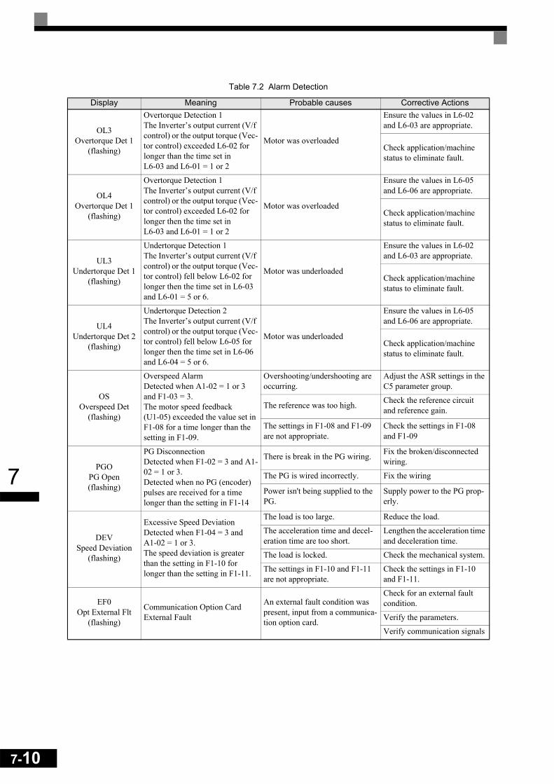
7-10
7
OL3Overtorque Det 1
(flashing)
Overtorque Detection 1The Inverter’s output current (V/f control) or the output torque (Vec-tor control) exceeded L6-02 for longer than the time set in L6-03 and L6-01 = 1 or 2
Motor was overloaded
Ensure the values in L6-02 and L6-03 are appropriate.
Check application/machine status to eliminate fault.
OL4Overtorque Det 1
(flashing)
Overtorque Detection 1The Inverter’s output current (V/f control) or the output torque (Vec-tor control) exceeded L6-02 for longer then the time set in L6-03 and L6-01 = 1 or 2
Motor was overloaded
Ensure the values in L6-05 and L6-06 are appropriate.
Check application/machine status to eliminate fault.
UL3Undertorque Det 1
(flashing)
Undertorque Detection 1The Inverter’s output current (V/f control) or the output torque (Vec-tor control) fell below L6-02 for longer then the time set in L6-03 and L6-01 = 5 or 6.
Motor was underloaded
Ensure the values in L6-02 and L6-03 are appropriate.
Check application/machine status to eliminate fault.
UL4Undertorque Det 2
(flashing)
Undertorque Detection 2The Inverter’s output current (V/f control) or the output torque (Vec-tor control) fell below L6-05 for longer then the time set in L6-06 and L6-04 = 5 or 6.
Motor was underloaded
Ensure the values in L6-05 and L6-06 are appropriate.
Check application/machine status to eliminate fault.
OSOverspeed Det
(flashing)
Overspeed AlarmDetected when A1-02 = 1 or 3 and F1-03 = 3.The motor speed feedback (U1-05) exceeded the value set in F1-08 for a time longer than the setting in F1-09.
Overshooting/undershooting are occurring.
Adjust the ASR settings in the C5 parameter group.
The reference was too high. Check the reference circuit and reference gain.
The settings in F1-08 and F1-09 are not appropriate.
Check the settings in F1-08 and F1-09
PGOPG Open(flashing)
PG DisconnectionDetected when F1-02 = 3 and A1-02 = 1 or 3.Detected when no PG (encoder) pulses are received for a time longer than the setting in F1-14
There is break in the PG wiring. Fix the broken/disconnected wiring.
The PG is wired incorrectly. Fix the wiring
Power isn't being supplied to the PG.
Supply power to the PG prop-erly.
DEVSpeed Deviation
(flashing)
Excessive Speed DeviationDetected when F1-04 = 3 and A1-02 = 1 or 3.The speed deviation is greater than the setting in F1-10 for longer than the setting in F1-11.
The load is too large. Reduce the load.
The acceleration time and decel-eration time are too short.
Lengthen the acceleration time and deceleration time.
The load is locked. Check the mechanical system.
The settings in F1-10 and F1-11 are not appropriate.
Check the settings in F1-10 and F1-11.
EF0Opt External Flt
(flashing)
Communication Option Card External Fault
An external fault condition was present, input from a communica-tion option card.
Check for an external fault condition.
Verify the parameters.
Verify communication signals
Table 7.2 Alarm Detection
Display Meaning Probable causes Corrective Actions
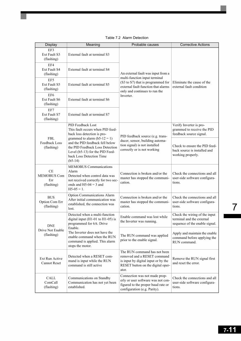
7
EF3Ext Fault S3
(flashing)External fault at terminal S3
An external fault was input from a multi-function input terminal (S3 to S7) that is programmed for external fault function that alarms only and continues to run the Inverter.
Eliminate the cause of the external fault condition
EF4Ext Fault S4
(flashing)External fault at terminal S4
EF5Ext Fault S5
(flashing)External fault at terminal S5
EF6Ext Fault S6
(flashing)External fault at terminal S6
EF7Ext Fault S7
(flashing)External fault at terminal S7
FBLFeedback Loss
(flashing)
PID Feedback LostThis fault occurs when PID feed-back loss detection is pro-grammed to alarm (b5-12 = 1) and the PID feedback fell below the PID Feedback Loss Detection Level (b5-13) for the PID Feed-back Loss Detection Time (b5-14)
PID feedback source (e.g. trans-ducer, sensor, building automa-tion signal) is not installed correctly or is not working
Verify Inverter is pro-grammed to receive the PID feedback source signal.
Check to ensure the PID feed-back source is installed and working properly.
CEMEMOBUS Com
Err(flashing)
MEMOBUS Communications AlarmDetected when control data was not received correctly for two sec-onds and H5-04 = 3 and H5-05 = 1.
Connection is broken and/or the master has stopped the communi-cation.
Check the connections and all user-side software configura-tions.
BUSOption Com Err
(flashing)
Option Communications AlarmAfter initial communication was established, the connection was lost.
Connection is broken and/or the master has stopped the communi-cation.
Check the connections and all user-side software configura-tions.
DNEDrive Not Enable
(flashing)
Detected when a multi-function digital input (H1-01 to H1-05) is programmed for 6A: Drive Enable.The Inverter does not have the enable command when the RUN command is applied. This alarm stops the motor.
Enable command was lost while the Inverter was running.
Check the wiring of the input terminal and the external sequence of the enable signal.
The RUN command was applied prior to the enable signal.
Apply and maintain the enable command before applying the RUN command.
Ext Run ActiveCannot Reset
Detected when a RESET com-mand is input while the RUN command is still active
The RUN command has not been removed and a RESET command is input by digital input or by the RESET button on the digital oper-ator.
Remove the RUN signal first and reset the error.
CALLComCall(flashing)
Communications on StandbyCommunication has not yet been established.
Connection was not made prop-erly or user software was not con-figured to the proper baud rate or configuration (e.g. Parity).
Check the connections and all user-side software configura-tions.
Table 7.2 Alarm Detection
Display Meaning Probable causes Corrective Actions
7-11
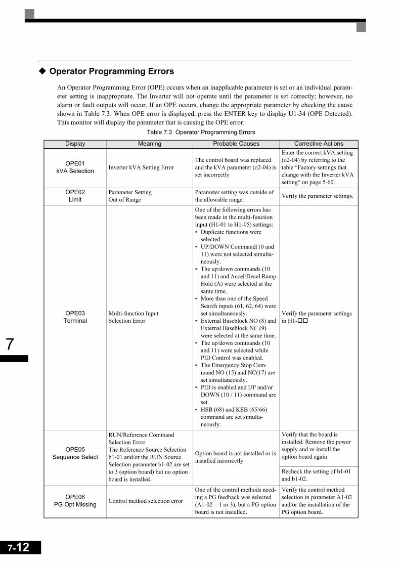
7-12
7
Operator Programming Errors
An Operator Programming Error (OPE) occurs when an inapplicable parameter is set or an individual param-eter setting is inappropriate. The Inverter will not operate until the parameter is set correctly; however, noalarm or fault outputs will occur. If an OPE occurs, change the appropriate parameter by checking the causeshown in Table 7.3. When OPE error is displayed, press the ENTER key to display U1-34 (OPE Detected).This monitor will display the parameter that is causing the OPE error.
Table 7.3 Operator Programming Errors
Display Meaning Probable Causes Corrective Actions
OPE01kVA Selection Inverter kVA Setting Error
The control board was replaced and the kVA parameter (o2-04) is set incorrectly
Enter the correct kVA setting (o2-04) by referring to the table “Factory settings that change with the Inverter kVA setting“ on page 5-60.
OPE02Limit
Parameter Setting Out of Range
Parameter setting was outside of the allowable range. Verify the parameter settings.
OPE03Terminal
Multi-function InputSelection Error
One of the following errors has been made in the multi-function input (H1-01 to H1-05) settings:• Duplicate functions were
selected.• UP/DOWN Command(10 and
11) were not selected simulta-neously.
• The up/down commands (10 and 11) and Accel/Decel Ramp Hold (A) were selected at the same time.
• More than one of the Speed Search inputs (61, 62, 64) were set simultaneously.
• External Baseblock NO (8) and External Baseblock NC (9) were selected at the same time.
• The up/down commands (10 and 11) were selected while PID Control was enabled.
• The Emergency Stop Com-mand NO (15) and NC(17) are set simultaneously.
• PID is enabled and UP and/or DOWN (10 / 11) command are set.
• HSB (68) and KEB (65/66) command are set simulta-neously.
Verify the parameter settings in H1-
OPE05Sequence Select
RUN/Reference Command Selection ErrorThe Reference Source Selection b1-01 and/or the RUN Source Selection parameter b1-02 are set to 3 (option board) but no option board is installed.
Option board is not installed or is installed incorrectly
Verify that the board is installed. Remove the power supply and re-install the option board again
Recheck the setting of b1-01 and b1-02.
OPE06PG Opt Missing Control method selection error
One of the control methods need-ing a PG feedback was selected (A1-02 = 1 or 3), but a PG option board is not installed.
Verify the control method selection in parameter A1-02 and/or the installation of the PG option board.

7
OPE07Analog Selection
Multi-function Analog Input/Pulse Train Input Error
The same function has been selected for the analog input selection and the pulse train input selection. • H3-09 = B and H6-01 = 1• H3-09 = C and H6-01 = 2b1-01 (Reference Source Selec-tion) is set to 4 (pulse train) and H6-01 (Pulse Train Input Func-tion Selection) is set to a value other than 0 (frequency refer-ence).
Check the parameters b1-01, H3-09 and H6-01.
OPE08Constant Selection Function Selection Error
A setting has been made that is applicable with the current con-trol method.Example: A function used only with open loop vector control was selected for V/f control.
Verify the control method and the function.
OPE09PID Selection PID Control Setup Error
The following settings have been made at the same time.• b5-01 (PID Control Mode
Selection) has been set to a value other than 0.
• b5-15 (PID Sleep Function Operation Level) has been set to a value other than 0.
• b1-03 (Stopping Method Selec-tion) has been set to 2 or 3.
Check parameters b5-01, b5-15 and b1-03.
OPE10V/f Ptrn Setting V/f Parameter Setting Error V/f parameter settings were out of
range.
Check parameters (E1- , E3- ). A frequency/volt-age value may be set higher than the maximum frequency/voltage.
OPE11CarrFrq/On-Delay
Carrier Frequency Parameter Set-ting Error
One of the following parameter setting errors exists.• Carrier frequency Gain
C6-05 > 6 and C6-03 (Carrier Frequency Upper Limit) < C6-04 (Carrier Frequency Lower Limit)
• Upper/lower limit error in C6-03 and 04.
• C6-01 = 0 and C6-02 = 2 to 6.• C6-01 = 1 and C6-02 = 7 to E.
Check the parameter settings.
ERREEPROM R/W Err
EEPROM write errorThe NV-RAM data does not match the EEPROM data.
A verification error occurred when writing EEPROM.
Cycle power to the Inverter.
Do a factory initialization (A1-03)
Table 7.3 Operator Programming Errors
Display Meaning Probable Causes Corrective Actions
7-13

7-14
7
Auto-tuning Fault
Auto-tuning faults are shown below. When the following faults are detected, the fault is displayed on the digi-tal operator and the motor coasts to stop. No fault or alarm outputs will be operated.
Table 7.4 Auto-tuning Faults
Display Meaning Probable causes Corrective Actions
Er - 01Fault Motor data fault
There is an error in the data input for autotuning. Check the input data.
There is an error in the relation-ship between the motor output and the motor rated current.
Check the Inverter and motor capacity.
There is an error between the no-load current setting and the input motor rated current (when auto-tuning for line-to-line resistance is performed for vector control)
Check the motor rated current and no-load current.
Er - 02Minor Fault Alarm An alarm is detected during auto-
tuning.
Check the input data.
Check wiring and the machine.
Check the load.
Er - 03STOP key STOP key input The STOP key was pressed to
cancel autotuning. -
Er - 04Resistance Line-to-Line Resistance Fault
Autotuning was not completed in the specified time.
The auto-tuning result is outside the parameter setting range.
• Check the input data.• Check motor wiring.• If the motor is connected to
the machine, disconnect it.• If the setting of T1-03 is
higher than the Inverter input power supply voltage (E1-01), change the input data.
Er - 05No-Load Current No-Load Current Fault
Er - 08Rated slip Rated Slip Fault
Er - 09Accelerate
Acceleration FaultDetected only for rotating auto-tuning
The motor did not accelerate in the specified time (C1-01 + 10 sec)
• Increase C1-01 (Accelera-tion Time 1).
• Increase L7-01 and L7-02 (Torque Limits) if they are low.
• If the motor is connected to the machine, disconnect it.
Er - 11Motor Speed
Motor speed FaultDetected only for rotating auto-tuning
The torque reference exceeded 100% during acceleration.Detected when A1-02 = 2 or 3 (Vector control).
• If the motor is connected to the machine, disconnect it.
• Increase C1-01 (Accelera-tion Time 1).
• Check the input data (partic-ularly the number of PG pulses and the number of motor poles).
Er - 12I-det. Circuit Current Detection Fault
The current exceeded the motor rated current.
Check wiring of the Inverter and the mounting.
Any of U/T1, V/T2 and W/T3 has open-phase
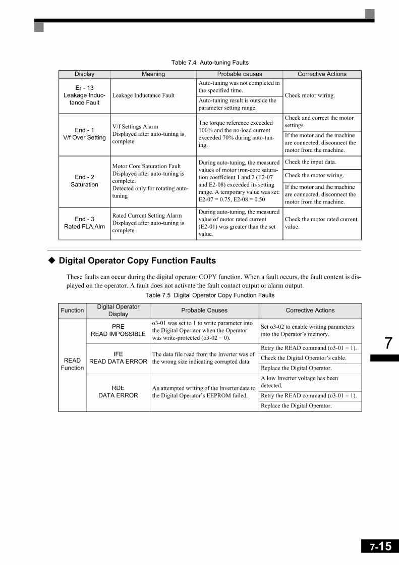
7
Digital Operator Copy Function Faults
These faults can occur during the digital operator COPY function. When a fault occurs, the fault content is dis-played on the operator. A fault does not activate the fault contact output or alarm output.
Er - 13Leakage Induc-
tance FaultLeakage Inductance Fault
Auto-tuning was not completed in the specified time.
Check motor wiring.Auto-tuning result is outside the parameter setting range.
End - 1V/f Over Setting
V/f Settings AlarmDisplayed after auto-tuning is complete
The torque reference exceeded 100% and the no-load current exceeded 70% during auto-tun-ing.
Check and correct the motor settings
If the motor and the machine are connected, disconnect the motor from the machine.
End - 2Saturation
Motor Core Saturation FaultDisplayed after auto-tuning is complete. Detected only for rotating auto-tuning
During auto-tuning, the measured values of motor iron-core satura-tion coefficient 1 and 2 (E2-07 and E2-08) exceeded its setting range. A temporary value was set: E2-07 = 0.75, E2-08 = 0.50
Check the input data.
Check the motor wiring.
If the motor and the machine are connected, disconnect the motor from the machine.
End - 3Rated FLA Alm
Rated Current Setting AlarmDisplayed after auto-tuning is complete
During auto-tuning, the measured value of motor rated current (E2-01) was greater than the set value.
Check the motor rated current value.
Table 7.5 Digital Operator Copy Function Faults
Function Digital Operator Display Probable Causes Corrective Actions
READ Function
PREREAD IMPOSSIBLE
o3-01 was set to 1 to write parameter into the Digital Operator when the Operator was write-protected (o3-02 = 0).
Set o3-02 to enable writing parameters into the Operator’s memory.
IFE READ DATA ERROR
The data file read from the Inverter was of the wrong size indicating corrupted data.
Retry the READ command (o3-01 = 1).
Check the Digital Operator’s cable.
Replace the Digital Operator.
RDEDATA ERROR
An attempted writing of the Inverter data to the Digital Operator’s EEPROM failed.
A low Inverter voltage has been detected.
Retry the READ command (o3-01 = 1).
Replace the Digital Operator.
Table 7.4 Auto-tuning Faults
Display Meaning Probable causes Corrective Actions
7-15

7-16
7
COPY Function
CPEID UNMATCHED
The Inverter type or software number was different from the stored data in the digital operator
Use stored data of the same product (F7) and software number (U1-14) only.
VAE INV. KVA UNMATCH
The capacity of the Inverter and the capac-ity of the stored data in the Digital Operator are different.
Use stored data for the same Inverter capacity only (o2-04).
CRECONTROL
UNMATCHED
The control method of the Inverter and the control method of the stored data in the Digital Operator are different.
Use stored data for the same control method (A1-02).
CYE COPY ERROR
A parameter setting written to the Inverter was different from the setting stored in the Digital Operator.
Retry the COPY function (o3-01 = 2)
CSESUM CHECK ERROR
Upon completion of the COPY function, the Inverter’s data checksum was different than the digital operator’s data checksum.
Retry the COPY function (o3-01 = 2)
VerifyFunction
VYEVERIFY ERROR
The set value of the digital operator and the Inverter do not match Retry the Verify function (o3-01 = 3)
Table 7.5 Digital Operator Copy Function Faults
Function Digital Operator Display Probable Causes Corrective Actions

7
Troubleshooting
Due to parameter setting errors, faulty wiring, and so on, the Inverter and motor may not operate as expectedwhen the system is started. If that occurs, use this section as a reference and perform the appropriate counter-measures.
If the contents of the fault are displayed, refer to page -2, Protective and Diagnostic Functions.
If A Parameter Cannot Be Set
Use the following information if a parameter cannot be set.
The display does not change when the Increment and Decrement keys are pressed.The following causes are possible:
The Inverter is operating (drive mode).There are some parameters that cannot be set during operation. Turn off the RUN command and then set theparameters
Parameter write enable is input.This occurs when "Parameter Write Enable" (set value: 1B) is set for a multi-function input terminal (H1-01 toH1-05). If the Parameter Write Enable input is OFF, the parameters cannot be changed. Turn it ON and thenset the parameters.
Passwords do not match. (Only when a password is set.)If the parameter A1-04 (Password) and A1-05 (Password Setting) settings are different, the parameters for theinitialize mode cannot be changed. Enter the correct password in A1-04.
If you cannot remember the password, display A1-05 (Password Setting) by pressing the Shift/RESET keyand the MENU key simultaneously while in the A1-04 display. Then set the password and input the set pass-word in parameter A1-04.
OPE01 through OPE11 is displayed.The set value for the parameter is wrong. Refer to Table 7.3 in this chapter and correct the settings.
CPF00 or CPF01 is displayed.This is a Digital Operator communication error. The connection between the Digital Operator and the Invertermay be faulty. Remove the Digital Operator and then re-install it.
7-17
7-18
7
If the Motor Does Not Operate Properly
The following causes are possible:
Ensure the Digital Operator is securely connected to the Inverter.
The motor does not operate when the RUN key on the Digital Operator is pressed.The following causes are possible:
The LOCAL/REMOTE mode is not selected properly.The status of the SEQ and the REF LEDs have to be OFF for LOCAL mode. Press the LOCAL/REMOTE keyto switch between the two modes or check if there is a multi-function digital input programmed to LOCAL/REMOTE selection (H1- = 1).
The Inverter is not in drive modeIf the Inverter is not in Drive mode, it will not start. Press the MENU key once and then press the DATA/ENTER key. The Inverter is now in drive mode.
The Frequency Reference is too lowIf the frequency reference is set below the frequency set in E1-09 (Minimum Output Frequency), the Inverterwill not operate. Raise the frequency reference to at least the minimum output frequency.
There is a multi-function analog input setting error.If multi-function analog input H3-09 is set to 1 (frequency gain), and if no voltage (current) is input, then thefrequency reference will be zero. Check to be sure that the set value and analog input value are correct.
The motor does not operate when an external operation signal is input.The following causes are possible:
The Inverter is not in drive mode.If the Inverter is not in Drive mode, it will not start. Press the MENU key once and then press the DATA/ENTER key. The Inverter is now in drive mode.
The LOCAL/REMOTE mode is not selected properly.The status of the SEQ and the REF LEDs have to be ON for REMOTE mode. Press the LOCAL/REMOTEkey to switch between the two modes or check if there is a multi-function digital input programmed toLOCAL/REMOTE selection (H1- = 1).
The Frequency Reference is too lowIf the frequency reference is set below the frequency set in E1-09 (Minimum Output Frequency), the Inverterwill not operate. Raise the frequency reference to at least the minimum output frequency.
The motor stops during acceleration or when a load is connected.The load may be too large. The motor’s responsiveness limit may be exceeded if it is accelerated too rapidlyby the Inverter’s stall prevention function or automatic torque boost function. Increase the acceleration time(C1-01) or reduce the motor load. Also, consider increasing the motor size.
7
The motor only rotates in one direction."Reverse run disabled" may be selected. If b1-04 (Prohibition of Reverse Operation) is set to 1 (reverse runprohibited), the Inverter will not accept any reverse run commands.
If the Direction of the Motor Rotation is Reversed
If the motor rotates in the wrong direction, the motor output wiring may be incorrect. When the Inverter oper-ates in the forward direction, the forward direction of the motor will depend on the manufacturer and themotor type, so be sure to check the motor specification
The direction of the motor rotation can be reversed by switching two wires among U, V, and W. If using anencoder, the polarity will also have to be switched. If the Inverter is operated in V/f mode also parameter b1-04 can be used to change the rotation direction.
If the Motor Stalls or Acceleration is Slow
The torque limit has been reached.When a torque limit has been set in parameters L7-01 to L7-04, the output torque will be limited accordingthese settings. Therefore the motor may not develop enough torque to accelerate or the acceleration time mightbe very long.
If torque limits have been set for the multi-function analog input (H3-09 = 10 to 12 or 15), check the signals.
The stall prevention level during acceleration is too low.If the value set for L3-02 (Stall Prevention Level during Acceleration) is too low, the acceleration time will beincreased. Check that the set value is suitable and that the load is not too large for the motor.
The stall prevention level during running is too low.If the value set for L3-06 (Stall Prevention Level during Running) is too low, the motor speed and torque willbe limited. Check that the set value is suitable and that the load is not too large for the motor.
Auto-tuning has not been performed for vector controlVector control will not work properly if auto-tuning has not been performed. Perform auto-tuning, or set themotor parameters through calculations.
7-19

7-20
7
If the Motor Operates at Higher Speed than the Frequency Reference
PID control is enabled.If the PID control is enabled (b5-01 = 1 to 4), the Inverter output frequency will change to regulate the processvariable to the desired set point. The PID can command a speed up to Maximum Output Frequency (E1-04)even though the reference is much lower.
If There is Low Speed Control Accuracy Above Base Speed in Open Loop Vector Control Mode
The Inverter’s maximum output voltage is determined by its input voltage. (For example, if 400 VAC is input,then the maximum output voltage will be 400 VAC). Vector control uses voltage to control the currents withinthe motor. If the vector control voltage reference value exceeds the Inverter output voltage capability, thespeed control accuracy will decrease because the motor currents cannot be properly controlled. Use a motorwith a low rated voltage compared to the input voltage, or change to Closed Loop Vector control.
If Motor Deceleration is Slow
The following causes are possible:
The deceleration time is long even when braking resistor is connected.The following causes are possible:
Stall Prevention During Deceleration is enabled.When a braking resistor is connected, set parameter L3-04 (Stall Prevention Selection during Deceleration) to0 (disabled) or 3 (with braking resistor). When this parameter is set to 1 (enabled, factory default), the stallprevention function will interfere with the braking resistor.
The deceleration time setting is too long.Check the deceleration time setting (parameters C1-02, C1-04, C1-06, and C1-08).
Motor torque is insufficient.If the parameters are correct and there is no overvoltage fault, then the motor's power may be insufficient.Consider increasing the motor and Inverter capacity.
The torque limit has been reached.When a torque limit is reached (L7-01 to L7-04), the motor torque will be limited. This can cause the deceler-ation time to be extended. Check to be sure that the value set for the torque limit is suitable.
If a torque limit has been set for the multi-function analog input terminal A2 Function (parameter H3-09 = 10to 12 or 15), check to be sure that the analog input value is suitable.

7
If the Motor Overheats
The following causes are possible:
The load is too large.If the motor load is too large and the torque exceeds the motor’s rated torque, the motor may overheat. Reducethe loads by either reducing the load or increasing the acceleration/deceleration times. Also consider increas-ing the motor size.
The ambient temperature is too high.The motor rating is determined by a particular ambient operating temperature range. The motor will overheatif it is run continuously at the rated torque in an environment where the maximum ambient operating tempera-ture is exceeded. Lower the motor's ambient temperature to be within its acceptable range.
Auto-tuning has not been performed for vector controlVector control may not perform efficiently if auto-tuning has not been performed. Perform auto-tuning, or setthe motor parameters through hand calculations. Alternatively, change the Control Mode Selection (A1-02) toV/f Control (0 or 1).
If Peripheral Devices Like PLCs or Others are Influenced by the Starting or Running Inverter
The following solutions are possible: • Change the Inverter's Carrier Frequency Selection (C6-02) to lower the carrier frequency. This will help to
reduce the amount of transistor switching noise.• Install an Input Noise Filter at the Inverter's input power terminals.• Install an Output Noise Filter at the Inverter's motor terminals.• Use shielded motor cables or a conduit. Metal shields electrical noise. • Check the grounding of the Inverter and motor.• Separate main circuit wiring from control circuit wiring.
If the Earth Leakage Breaker Operates When the Inverter is Running
The Inverter’s output is pulse modulated, i.e. the output voltage consists of high frequency pulses (PWM).This high frequency signal causes a certain amount of leakage current which may cause the earth leakagebreaker to operate and cut off the power supply. Change to a ground fault interrupter with a high leakagedetection level (i.e., a sensitivity current of 200 mA or higher, with an operating time of 0.1 s or more), or onethat incorporates high frequencies countermeasures (i.e., one designed for use with Inverters). It will also helpto some extent to lower the Inverter's Carrier Frequency Selection (C6-02). In addition, remember that theleakage current increases as the cable is lengthened.
7-21

7-22
7
If There is Mechanical Oscillation
Use the following information when there is mechanical vibration:
The application is making unusual sounds.The following causes are possible:
There may be resonance between the mechanical system's natural frequency and the carrier frequency.
This is characterized by the motor running with no noise generation, but the machinery vibrates with a high-pitched whine. To prevent this type of resonance, adjust the carrier frequency with parameters C6-02 toC6-05.
There may be resonance between a mechanical system’s natural frequency and the output fre-quency of the Inverter.
To prevent this resonance frequency use the Jump Frequency Function in parameters d3- , or have thedriven motor and load balanced to reduce vibration.
Oscillation and hunting occur with V/f controlThe torque compensation parameter settings may be incorrect for the machine. Adjust parameters C4-01(Torque Compensation Gain) and C4-02 (Torque Compensation Delay Time). Decrease C4-01 carefully insteps of 0.05 and/or increase C4-02.
Furthermore the Hunting Prevention Gain (n1-02) can be increased if the problems occur in light load condi-tions and the Slip Compensation Delay Time (C3-02) can be decreased.
Oscillation and hunting occur with V/f w/PG control.The parameter settings of the speed control loop (Automatic Speed Regulator, ASR) may be incorrect for themachine. Adjust the gains and integral times.
If the oscillation cannot be eliminated in this way, set the hunting prevention selection (n1-01) to disabled (set-ting 0) and then try adjusting the gain again.
Oscillation and hunting occur with Open Loop Vector control. The torque compensation parameter settings may be incorrect for the machine. Adjust parameters C4-01(Torque Compensation Gain), C4-02 (Torque Compensation Delay Time Parameter) and C3-02 (Slip Com-pensation Delay Time) in order. Lower the gain parameters and raise the delay time parameters.
If auto-tuning has not been performed, proper performance may not be achieved for Vector Control. Performauto-tuning or set the motor parameters through hand calculations. Alternatively, change the Control ModeSelection to V/f Control (A1-02 = 0 or 1)
Oscillation and hunting occur with Closed Loop Vector controlThe gain adjustment may be insufficient. Adjust the speed control loop (Automatic Speed Regulator, ASR) bychanging C5-01 (ASR Proportional Gain). If the oscillation points overlap with those of the machine and can-not be eliminated, increase the ASR Delay Time, and then readjust the ASR gain (C5-01)

7
If auto-tuning has not been performed, proper performance may not be achieved for Closed Loop Vector Con-trol. Perform auto-tuning or set the motor parameters through hand calculations. Alternatively, change theControl Mode Selection to V/f Control (A1-02 = 0 or 1).
Oscillation and hunting occur with PID control.If there is oscillation or hunting during PID control, check the oscillation cycle and individually adjust P, I,and D parameters. (Refer to page -96, Using PID Control.)
If the Motor Rotates Even When Inverter Output is Stopped
If the motor rotates after a deceleration when the Inverter is stopped due to a large inertial load, DC-injectionbraking may be necessary. Adjust the DC injection braking as follows.
• Increase parameter b2-02 (DC Injection Braking Current).• Increase parameter b2-04 (DC Injection Braking Time at Stop).
If Output Frequency Does Not Rise to Frequency Reference
The frequency reference is within the jump frequency range.When the jump frequency function is used, the output frequency does not change within the jump frequencyrange. Check to be sure that the Jump Frequency (d3-01 to d3-03) and Jump Frequency Width (d3-04) settingsare suitable.
The frequency reference upper limit has been reached.The output frequency upper limit is determined by the following formula:
Freq Ref Upper Limit = Max. Output Frequency (E1-04) x Frequency Reference Upper Limit (d2-01) /100
Check to be sure that the parameter E1-04 and d2-01 settings are suitable.
7-23

7-24
7
8 Maintenance and
InspectionThis chapter describes basic maintenance and inspection for the Inverter.
Maintenance and Inspection ..................................................8-2

8-2
8
Maintenance and Inspection
Periodic Inspection
Check the following items during periodic maintenance.• The motor should not vibrate or make unusual noises.• There should be no abnormal heat generation from the Inverter or motor. • The ambient temperature should be within the Inverter’s specifications.• The output current value shown in U1-30 should not be higher than the motor or the Inverter rated current
for extended period of time. • The cooling fan in the Inverter should be operating normally.
Before attempting any maintenance checks, make sure that the three-phase power is disconnected. With powerremoved from the unit, the DC bus capacitors will stay charged for several minutes. The Charge LED in theInverter will glow red until the DC bus voltage is below 10VDC. To ensure that the DC bus is completely dis-charged, measure between the positive and negative bus with a DC voltmeter set to the highest scale. Be surenot to touch terminals immediately after the power has been turned off. Doing so can result in electric shock.
Apply power to the Inverter and conduct the following inspection:
Item Inspection Corrective ProcedureExternal terminals
Mounting boltsConnectors
Are all screws and bolts tight? Tighten loose screws and bolts firmly.
Are connectors tight? Reconnect the loose connectors.
Cooling fins Are the fins dirty or dusty?Clean off any dirt and dust with an air gun using dry air at a pressure of 4 x 10⁵ to 6 x 10⁵ Pa (4 to 6 bar, 55 to 85 psi).
All PCBs Is there any conductive dirt or oil mist on the PCBs?
Clean off any dirt and dust with an air gun using dry air at a pressure of 4 x 10⁵ to 6 x 10⁵ Pa (4 to 6 bar, 55 to 85 psi).Replace the boards if they cannot be made clean.
Input DiodesOutput Transistors
Power Modules
Is there any conductive dirt or oil mist on the modules or components?
Clean off any dirt and dust with an air gun using dry air at a pressure of 4 x 10⁵ to 6 x 10⁵ Pa (4 to 6 bar, 55 to 85 psi).
DC bus capacitors Are there any irregularities, such as dis-coloration or odor? Replace the capacitor or Inverter.
Item Inspection Corrective Procedure
Cooling Fan(s)
Is there any abnormal noise or vibration, or has the total operating time exceeded 20,000 hours. Check U1-40 for the elapsed cooling oper-ation time.
Replace Cooling Fan
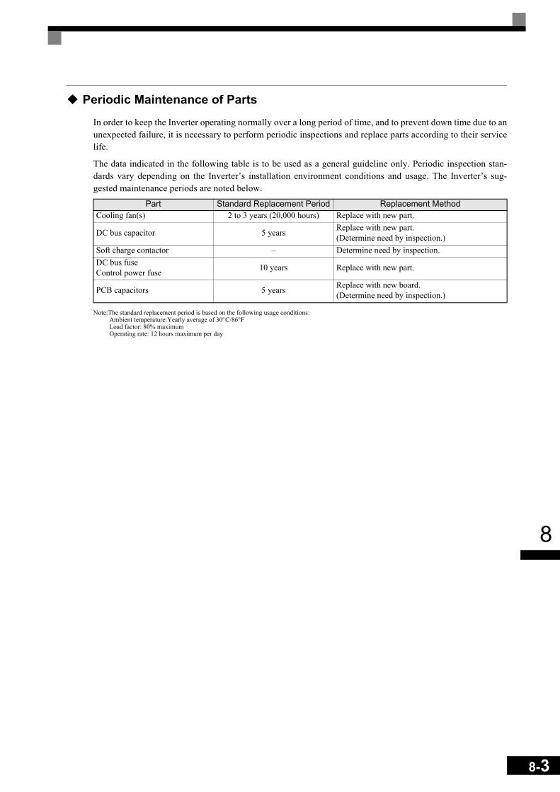
8
Periodic Maintenance of Parts
In order to keep the Inverter operating normally over a long period of time, and to prevent down time due to anunexpected failure, it is necessary to perform periodic inspections and replace parts according to their servicelife.
The data indicated in the following table is to be used as a general guideline only. Periodic inspection stan-dards vary depending on the Inverter’s installation environment conditions and usage. The Inverter’s sug-gested maintenance periods are noted below.
Note:The standard replacement period is based on the following usage conditions:Ambient temperature:Yearly average of 30°C/86°FLoad factor: 80% maximumOperating rate: 12 hours maximum per day
Part Standard Replacement Period Replacement MethodCooling fan(s) 2 to 3 years (20,000 hours) Replace with new part.
DC bus capacitor 5 years Replace with new part. (Determine need by inspection.)
Soft charge contactor – Determine need by inspection.DC bus fuseControl power fuse 10 years Replace with new part.
PCB capacitors 5 years Replace with new board. (Determine need by inspection.)
8-3

8-4
8
Cooling Fan Replacement
200 V and 400 V Class Inverters of 18.5 kW or LessA cooling fan is attached to the bottom of the Inverter.
If the Inverter is installed using the mounting holes on the back of the Inverter, the cooling fan can be replacedwithout removing the Inverter from the installation panel.
If the Inverter is mounted with the heatsink external to the enclosure, the cooling fan can only be replaced byremoving the Inverter from the enclosure.
Removing the Cooling Fan 1. Always turn OFF the input power before removing and installing the heatsink cooling fan.2. Press in on the right and left sides of the fan cover in the direction of arrows “1“ and when pull the fan out
in the direction of arrow “2“.3. Pull out the cable connected to the fan from the fan cover and disconnect the power connector.4. Open the fan cover on the left and right sides in direction of arrows “3“ and remove the fan cover from the
fan.
Fig 8.1 Cooling Fan Replacement (Inverters of 18.5 kW or Less)
Mounting the Cooling Fan1. Attach the fan cover to the cooling fan. Be sure that the air flow direction is correct (see figure above).2. Connect the cables securely and place the connector and cable into the fan cover.3. Mount the fan cover on the Inverter. Be sure that the tabs on the sides of the fan cover click into place on
the Inverter heatsink.
1
1
2
Fan cover
Powerconnector
3
Air flow direction
3
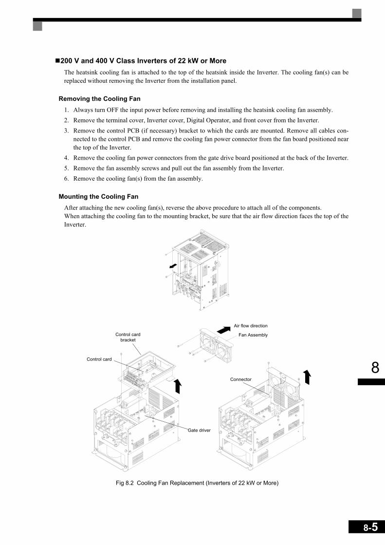
8
200 V and 400 V Class Inverters of 22 kW or MoreThe heatsink cooling fan is attached to the top of the heatsink inside the Inverter. The cooling fan(s) can bereplaced without removing the Inverter from the installation panel.
Removing the Cooling Fan1. Always turn OFF the input power before removing and installing the heatsink cooling fan assembly. 2. Remove the terminal cover, Inverter cover, Digital Operator, and front cover from the Inverter.3. Remove the control PCB (if necessary) bracket to which the cards are mounted. Remove all cables con-
nected to the control PCB and remove the cooling fan power connector from the fan board positioned nearthe top of the Inverter.
4. Remove the cooling fan power connectors from the gate drive board positioned at the back of the Inverter.5. Remove the fan assembly screws and pull out the fan assembly from the Inverter.6. Remove the cooling fan(s) from the fan assembly.
Mounting the Cooling FanAfter attaching the new cooling fan(s), reverse the above procedure to attach all of the components.When attaching the cooling fan to the mounting bracket, be sure that the air flow direction faces the top of theInverter.
Fig 8.2 Cooling Fan Replacement (Inverters of 22 kW or More)
Control card
Control cardbracket
Gate driver
Connector
Fan Assembly
Air flow direction
8-5
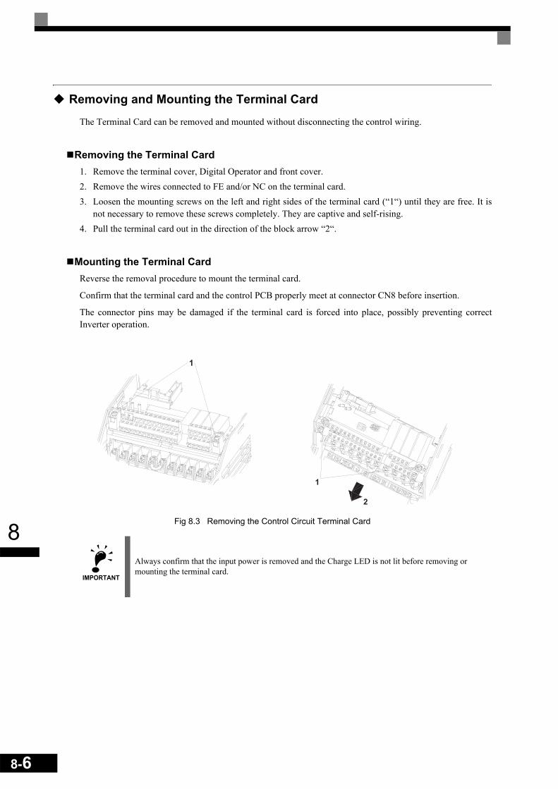
8-6
8
Removing and Mounting the Terminal Card
The Terminal Card can be removed and mounted without disconnecting the control wiring.
Removing the Terminal Card1. Remove the terminal cover, Digital Operator and front cover.2. Remove the wires connected to FE and/or NC on the terminal card. 3. Loosen the mounting screws on the left and right sides of the terminal card (“1“) until they are free. It is
not necessary to remove these screws completely. They are captive and self-rising.4. Pull the terminal card out in the direction of the block arrow “2“.
Mounting the Terminal CardReverse the removal procedure to mount the terminal card.
Confirm that the terminal card and the control PCB properly meet at connector CN8 before insertion.
The connector pins may be damaged if the terminal card is forced into place, possibly preventing correctInverter operation.
Fig 8.3 Removing the Control Circuit Terminal Card
IMPORTANT
Always confirm that the input power is removed and the Charge LED is not lit before removing or mounting the terminal card.
1
2
1

9Specifications
This chapter describes the basic specifications of the Inverter and specifications for options and peripheral devices.
Standard Inverter Specifications ............................................9-2
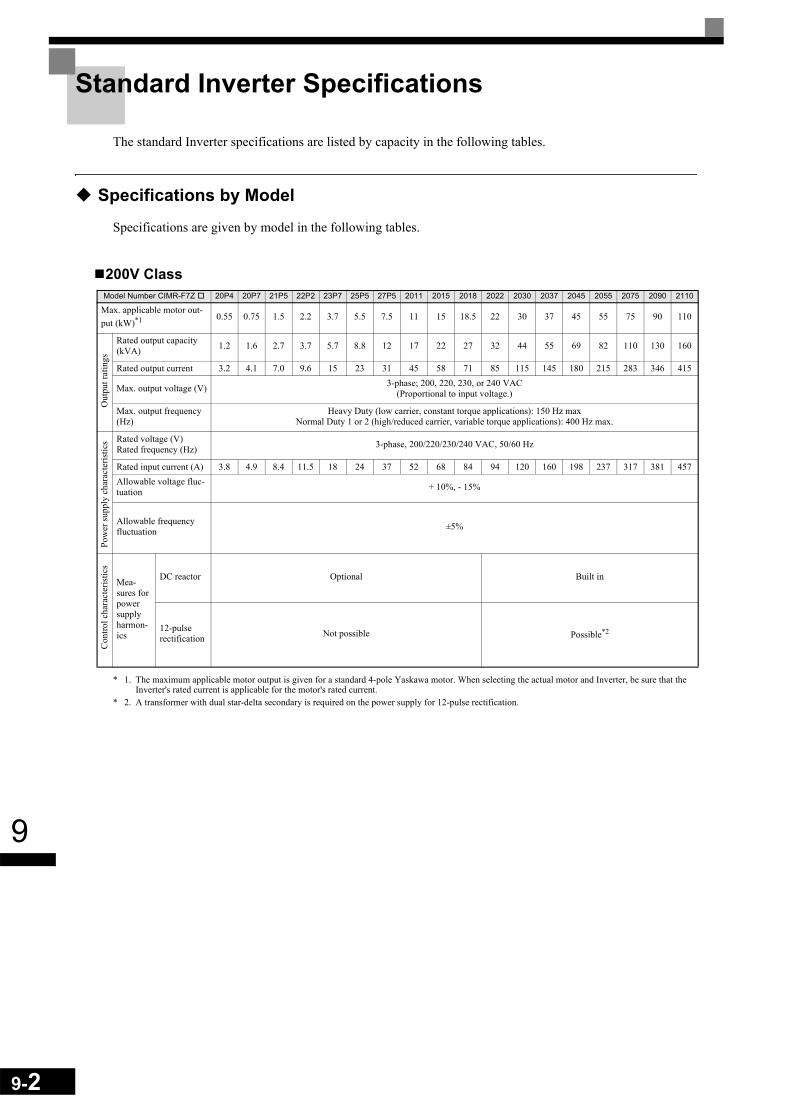
9-2
9
Standard Inverter Specifications
The standard Inverter specifications are listed by capacity in the following tables.
Specifications by Model
Specifications are given by model in the following tables.
200V Class
* 1. The maximum applicable motor output is given for a standard 4-pole Yaskawa motor. When selecting the actual motor and Inverter, be sure that the Inverter's rated current is applicable for the motor's rated current.
* 2. A transformer with dual star-delta secondary is required on the power supply for 12-pulse rectification.
Model Number CIMR-F7Z 20P4 20P7 21P5 22P2 23P7 25P5 27P5 2011 2015 2018 2022 2030 2037 2045 2055 2075 2090 2110
Max. applicable motor out-put (kW)*1 0.55 0.75 1.5 2.2 3.7 5.5 7.5 11 15 18.5 22 30 37 45 55 75 90 110
Rated output capacity (kVA) 1.2 1.6 2.7 3.7 5.7 8.8 12 17 22 27 32 44 55 69 82 110 130 160
Rated output current 3.2 4.1 7.0 9.6 15 23 31 45 58 71 85 115 145 180 215 283 346 415
Max. output voltage (V) 3-phase; 200, 220, 230, or 240 VAC (Proportional to input voltage.)
Max. output frequency (Hz)
Heavy Duty (low carrier, constant torque applications): 150 Hz maxNormal Duty 1 or 2 (high/reduced carrier, variable torque applications): 400 Hz max.
Rated voltage (V)Rated frequency (Hz) 3-phase, 200/220/230/240 VAC, 50/60 Hz
Rated input current (A) 3.8 4.9 8.4 11.5 18 24 37 52 68 84 94 120 160 198 237 317 381 457Allowable voltage fluc-tuation + 10%, - 15%
Allowable frequency fluctuation ±5%
Mea-sures for power supply harmon-ics
DC reactor Optional Built in
12-pulse rectification Not possible Possible*2
Out
put r
atin
gsPo
wer
supp
ly c
hara
cter
istic
sC
ontro
l cha
ract
eris
tics

9
400 V Class
* 1. The maximum applicable motor output is given for a standard 4-pole Yaskawa standard motor. When selecting the actual motor and Inverter, be sure that the Inverter's rated current is higher than the motor's rated current.
* 2. A transformer with dual star-delta secondary is required on the power supply for 12-pulse-rectification.
Model Number CIMR-F7Z 40P4 40P7 41P5 42P2 43P7 44P0 45P5 47P5 4011 4015 4018
Max. applicable motor output (kW) *1 0.55 0.75 1.5 2.2 3.7 4.0 5.5 7.5 11 15 18.5
Rated output capacity (kVA) 1.4 1.6 2.8 4.0 5.8 6.6 9.5 13 18 24 30
Rated output current (A) 1.8 2.1 3.7 5.3 7.6 8.7 12.5 17 24 31 39
Max. output voltage (V) 3-phase; 380, 400, 415, 440, 460, or 480 VAC (Proportional to input voltage.)
Max. output frequency (Hz)
Heavy Duty (low carrier, constant torque applications): 150 Hz max.Normal Duty 1 or 2 (high/reduced carrier, variable torque applications): 400 Hz max.
Rated voltage (V)Rated frequency (Hz) 3-phase, 380, 400, 415, 440, 460 or 480 VAC, 50/60 Hz
Rated input current (A) 2.2 2.5 4.4 6.4 9.0 10.4 15 20 29 37 47
Allowable voltage fluctua-tion + 10%, - 15%
Allowable frequency fluc-tuation ±5%
Measures for power supply harmonics
DC reactor Optional
12-phase rec-tification Not possible
Model Number CIMR-F7Z 4022 4030 4037 4045 4055 4075 4090 4110 4132 4160 4185 4220 4300
Max. applicable motor output (kW)*1 22 30 37 45 55 75 90 110 132 160 185 220 300
Rated output capacity (kVA) 34 46 57 69 85 110 140 160 200 230 280 390 510
Rated output current (A) 45 60 75 91 112 150 180 216 260 304 370 506 675
Max. output voltage (V) 3-phase, 380, 400, 415, 440, 460, or 480 VAC (Proportional to input voltage.)
Max. output frequency (Hz)
Heavy Duty (low carrier, constant torque applications): 150 Hz max.Normal Duty 1 or 2 (high/reduced carrier, variable torque applications): 400 Hz max.
Max. voltage (V)Rated frequency (Hz) 3-phase, 380, 400, 415, 440, 460, or 480 VAC, 50/60 Hz
Rated input current (A) 50 66 83 100 120 165 198 238 286 334 407 537 743
Allowable voltage fluctua-tion + 10%, - 15%
Allowable frequency fluc-tuation ±5%
Measures for power supply harmonics
DC reactor Built in
12-phase rec-tification Possible*2
Out
put r
atin
gsPo
wer
supp
ly c
hara
cter
istic
sC
ontro
l cha
ract
eris
tics
Out
put r
atin
gsPo
wer
supp
ly c
hara
cter
istic
sC
ontro
l cha
ract
eris
tics
9-3

9-4
9
Common Specifications
The following specifications apply to both 200 V and 400 V class Inverters.Model NumberCIMR-F7Z Specification
Control method Sine wave PWMClosed Loop Vector control, Open Loop Vector control, V/f control, V/f with PG control
Torque characteristics
Heavy Duty (low carrier, constant torque applications): 2 kHz carrier frequency, 150% overload for 1 minute, higher carrier frequency possible with current derating.
Normal Duty 1 (high carrier, variable torque applications): maximum carrier frequency, depending on inverter capacity, 120% overload for 1 minute.
Normal Duty 2 (variable torque applications): carrier frequency reduced, continuous overload capability increased
Speed control range1:40 (V/f control)
1:100 (Open Loop Vector control)1:1000 (Closed Loop Vector control)
Speed control accuracy
± 3% (V/f control)± 0.03% (V/f control with PG)
± 0.2% (Open Loop Vector control)± 0.02% (Closed Loop Vector control)
(25°C ± 10°C)
Speed control response 5 Hz (control without PG)30 Hz (control with PG)
Torque limits Provided (4 quadrant steps can be changed by constant settings.) (Vector control)
Torque accuracy ± 5%
Frequency range 0.01 to 150 Hz (Heavy Duty), 0.01 to 400 Hz (Normal Duty 1 or 2)
Frequency accuracy (tem-perature characteristics)
Digital references: ± 0.01% (-10°C to +40°C)
Analog references: ± 0.1% (25°C ±10°C)
Frequency setting resolu-tion
Digital references: 0.01 Hz
Analog references: 0.025/50 Hz (11 bits plus sign)
Output frequency resolu-tion 0.01 Hz
Overload capacity and maximum current
Heavy Duty (low carrier, constant torque applications): 150% of rated output current for 1 minuteNormal Duty 1 or 2 (high/reduced carrier, variable torque applications): 120% of rated output current for 1 minute
Frequency setting signal 0 to +10V, –10 to +10 V, 4 to 20 mA, pulse train
Acceleration/Decelera-tion time 0.01 to 6000.0 s (4 selectable combinations of independent acceleration and deceleration time settings)
Braking torque Approximately 20% (Approximately 125% with Braking Resistor option, braking transistor built into Inverters of 18.5 kW or less)
Main control functions
Restarting after momentary power loss, speed search, overtorque/undertorque detection, torque limits, 17-speed control (max-imum), 4 acceleration and deceleration times, S-curve acceleration/deceleration, 3-wire control, auto-tuning (rotational or sta-tionary), dwell function, cooling fan ON/OFF control, slip compensation, torque compensation, auto-restart after fault, jump
frequencies, upper and lower limits for frequency references, DC braking for starting and stopping, high-slip braking, advanced PID control, energy-saving control, MEMOBUS communications (RS-485/422, 19.2 kbps maximum), 2 motor
parameter sets, fault reset and parameter copy function.
Motor protection Protection by electronic thermal overload relay.
Instantaneous overcurrent protection Stops at approx. 200% of rated output current.
Fuse blown protection Stops for fuse blown.
Overload protection
Heavy Duty (low carrier, constant torque applications): 150% of rated output current for 1 minuteNormal Duty 1 (high carrier, variable torque applications): 120% of rated output current for 1 minuteNormal Duty 2 (high carrier, variable torque applications): 120% of rated output current for 1 minute,
increased continuous output current.
Overvoltage protection 200 Class Inverter: Stops when main-circuit DC voltage is above 410 V.400 Class Inverter: Stops when main-circuit DC voltage is above 820 V.
Undervoltage protection 200 Class Inverter: Stops when main-circuit DC voltage is below 190 V.400 Class Inverter: Stops when main-circuit DC voltage is below 380 V.
Momentary power loss ride through By selecting the momentary power loss method, operation can be continued if power is restored within 2 s.
Cooling fin overheating Protection by thermistor.
Stall prevention Stall prevention during acceleration, deceleration and running independently.
Grounding protection Protection by electronic circuits.
Charge indicator Glows when the main circuit DC voltage is approx. 10 VDC or more.
Protective structure Enclosed wall-mounted type (NEMA 1): 18.5 kW or less (same for 200 V and 400 V class Inverters)Open chassis type (IP00): 22 kW or more (same for 200 V and 400 V class Inverters)
Con
trol c
hara
cter
istic
sPr
otec
tive
func
tions

9
Ambient operating tem-perature
-10°C to 40°C (Enclosed wall-mounted type)–10°C to 45°C (Open chassis type)
Ambient operating humid-ity 95% max. (with no condensation)
Storage temperature - 20°C to + 60°C (short-term temperature during transportation)
Application site Indoor (no corrosive gas, dust, etc.)
Altitude 1000 m max.
Vibration 10 to 20 Hz, 9.8 m/s2 max.; 20 to 50 Hz, 2 m/s2 max
Model NumberCIMR-F7Z Specification
Envi
ronm
ent
9-5

9-6
9

10Appendix
This chapter provides precautions for the Inverter, motor, andperipheral devices and also provides lists of constants.
Inverter Application Precautions ..........................................10-2 Motor Application Precautions .............................................10-5 User Constants ....................................................................10-7
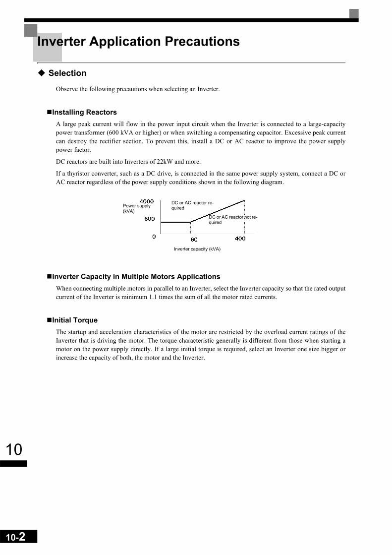
10-2
10
Inverter Application Precautions
Selection
Observe the following precautions when selecting an Inverter.
Installing ReactorsA large peak current will flow in the power input circuit when the Inverter is connected to a large-capacitypower transformer (600 kVA or higher) or when switching a compensating capacitor. Excessive peak currentcan destroy the rectifier section. To prevent this, install a DC or AC reactor to improve the power supplypower factor.
DC reactors are built into Inverters of 22kW and more.
If a thyristor converter, such as a DC drive, is connected in the same power supply system, connect a DC orAC reactor regardless of the power supply conditions shown in the following diagram.
Inverter Capacity in Multiple Motors ApplicationsWhen connecting multiple motors in parallel to an Inverter, select the Inverter capacity so that the rated outputcurrent of the Inverter is minimum 1.1 times the sum of all the motor rated currents.
Initial TorqueThe startup and acceleration characteristics of the motor are restricted by the overload current ratings of theInverter that is driving the motor. The torque characteristic generally is different from those when starting amotor on the power supply directly. If a large initial torque is required, select an Inverter one size bigger orincrease the capacity of both, the motor and the Inverter.
Power supply (kVA)
DC or AC reactor re-quired
DC or AC reactor not re-quired
Inverter capacity (kVA)

10
Installation
Observe the following precautions when installing an Inverter.
Installation in EnclosuresInstall the Inverter in a clean location where it is not subjected to oil mist, dust, and other contaminants, orinstall the Inverter in a completely enclosed panel. Provide cooling measures and sufficient panel space so thatthe temperature surrounding the Inverter does not exceed the allowable temperature. Do not install the Inverteron wood or other combustible materials.
Installation DirectionMount the Inverter vertically to a wall or other vertical surface.
Settings
Observe the following precautions when making settings for an Inverter.
Upper LimitsThe maximum output frequency can be set up to 400Hz. Setting the output frequency too high can damage themachine. So pay attention to the mechanical system and observe required limits for the output frequency.
DC Injection BrakingIf the DC Injection Braking Current or the Braking Time are set too high the motor can overheat what candamage the motor
Acceleration/Deceleration TimesThe motor's acceleration and deceleration times are determined by the torque generated by the motor, the loadtorque, and the load's inertial moment (GD2/4). If the stall prevention functions are activated during accelera-tion or deceleration, it might be necessary to increase the acceleration or deceleration time.
To reduce the acceleration or deceleration times, increase the capacity of the motor and Inverter.
10-3

10-4
10
Handling
Observe the following precautions when wiring or performing maintenance for an Inverter.
Wiring CheckThe Inverter will be internally damaged if the power supply voltage is applied to output terminal U, V, or W.Check wiring for any mistakes before supplying power. Check all wiring and control sequences carefully.
Magnetic Contactor InstallationIf a magnetic contactor is installed in the power supply line do not exceed one start per hour. Switching moreoften can damage the inrush current prevention circuit.
Maintenance and InspectionsAfter turning OFF the main circuit power supply it can take several minutes before the DC bus is dischargedcompletely. The CHARGE LED, indicating if the DC bus is charged, glows above a voltage of 10VD.

10
Motor Application Precautions
Using the Inverter for an Existing Standard Motor
Observe the following precautions when using an Inverter for an existing standard motor.
Low Speed RangesIf a standard cooled motor is used at low speed the cooling effects are diminished. If the motor is used in con-stant torque applications in low speed area the motor may overheat. If full torque is required at low speed con-tinuously an externally cooled motor must be used.
Installation Withstand VoltageIf the inverter is used with an input voltage of 440 V or higher and long motor cables, voltage spikes at themotor terminals may occur which can damage the motor windings. Please ensure that the motor insulationclass is sufficient.
High-speed OperationWhen using the motor at a speed higher than the motor rated frequency (usually 50 Hz), problems may arise indynamic balance and bearing durability.
Acoustic NoiseThe noise generated in the motor depends on the carrier frequency. The higher the setting the less the gener-ated noise is.
Using the Inverter for Special Motors
Observe the following precautions when using a special motor.
Pole-changing MotorThe rated input current of pole-changing motors differs from that of standard motors. Select an appropriateInverter according to the maximum current of the motor.
Submersible MotorThe rated input current of submersible motors is higher than that of standard motors. Therefore, always selectan appropriate Inverter according to the maximum current of the motor.
Explosion-proof MotorWhen an explosion-proof motor is used, it must be subjected to an explosion-proof test in conjunction with theInverter. This is also applicable when an existing explosion-proof motor is to be operated with the Inverter.Since the Inverter itself is, however, not explosion-proof, always install it in a safe place.
Gear motorThe speed range for continuous operation differs according to the lubrication method and motor manufacturer.In particular, continuous operation of an oil-lubricated motor in the low speed range may result in damaging.If the motor is to be operated at a speed higher than 50 Hz, consult the manufacturer.
10-5
10-6
10
Synchronous MotorA synchronous motor is not suitable for Inverter control.
Single-phase MotorDo not use an Inverter for a single-phase capacitor motor. Any capacitors directly connected to the inverteroutput may damage the Inverter.
Power Transmission Mechanism (Speed Reducers, Belts and Chains)
If an oil-lubricated gearbox or speed reducer is used in the power transmission mechanism, oil lubrication willbe affected when the motor operates only in the low speed range. The power transmission mechanism willmake noise and experience problems with service life and durability if the motor is operated at low speedscontinuously.

10
User Constants
Factory settings are given in the following table. These are factory settings for a 200 V Class Inverter with 0.4kW (open loop vector control).
No. Name FactorySetting Setting
A1-00 Language selection for Digital Operator display 0
A1-01 Parameter access level 2
A1-02 Control method selection 2
A1-03 Initialize 0
A1-04 Password 0
A1-05 Password setting 0
A2-01 to A2-32 User specified parameters –
b1-01 Reference source selection 1
b1-02 RUN command source selection 1
b1-03 Stopping method selection 0
b1-04 Prohibition of reverse operation 0
b1-05 Operation selection for setting frequencies equal or lower than E1-09 0
b1-06 Control input scan 1
b1-07 Operation selection after switching to remote mode 0
b1-08 Run command selection in programming modes 0
b2-01 Zero speed level (DC injection braking starting frequency) 0.5 Hz
b2-02 DC injection braking current 50%
b2-03 DC injection braking time at start 0.00 s
b2-04 DC injection braking time at stop 0.50 s
b2-08 Magnetic flux compensation volume 0%
b3-01 Speed search selection (current detection or speed calculation) *1
b3-02 Speed search operating current (current detection) *1
b3-03 Speed search deceleration time (current detection) 2.0 s
b3-05 Speed search wait time (current detection or speed calculation) 0.2 s
b3-10 Speed Search Compensation Gain (speed calculation only) 1.10
b3-14 Speed Search Rotating Selection Direction 1
b4-01 Timer function ON-delay time 0.0 s
b4-02 Timer function OFF-delay time 0.0 s
b5-01 PID control mode selection 0
b5-02 Proportional gain (P) 1.00
b5-03 Integral (I) time 1.0 s
b5-04 Integral (I) limit 100.0%
b5-05 Differential (D) time 0.00 s
b5-06 PID limit 100.0%
b5-07 PID offset adjustment 0.0%
b5-08 PID delay time constant 0.00 s
b5-09 PID output characteristics selection 0
b5-10 PID output gain 1.0
b5-11 PID reverse output selection 0
b5-12 Selection of PID feedback signal loss detection 0
b5-13 PID feedback loss detection level 0%
10-7
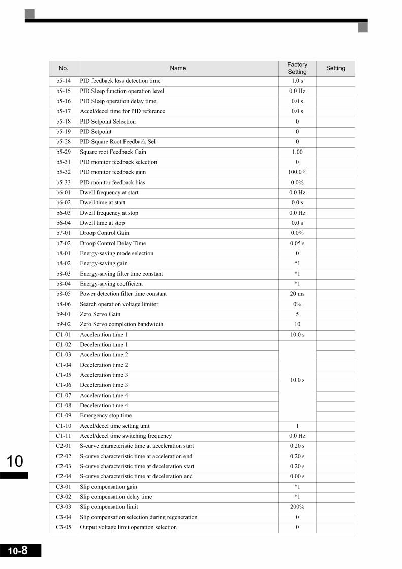
10-8
10
b5-14 PID feedback loss detection time 1.0 s
b5-15 PID Sleep function operation level 0.0 Hz
b5-16 PID Sleep operation delay time 0.0 s
b5-17 Accel/decel time for PID reference 0.0 s
b5-18 PID Setpoint Selection 0
b5-19 PID Setpoint 0
b5-28 PID Square Root Feedback Sel 0
b5-29 Square root Feedback Gain 1.00
b5-31 PID monitor feedback selection 0
b5-32 PID monitor feedback gain 100.0%
b5-33 PID monitor feedback bias 0.0%
b6-01 Dwell frequency at start 0.0 Hz
b6-02 Dwell time at start 0.0 s
b6-03 Dwell frequency at stop 0.0 Hz
b6-04 Dwell time at stop 0.0 s
b7-01 Droop Control Gain 0.0%
b7-02 Droop Control Delay Time 0.05 s
b8-01 Energy-saving mode selection 0
b8-02 Energy-saving gain *1
b8-03 Energy-saving filter time constant *1
b8-04 Energy-saving coefficient *1
b8-05 Power detection filter time constant 20 ms
b8-06 Search operation voltage limiter 0%
b9-01 Zero Servo Gain 5
b9-02 Zero Servo completion bandwidth 10
C1-01 Acceleration time 1 10.0 s
C1-02 Deceleration time 1
10.0 s
C1-03 Acceleration time 2
C1-04 Deceleration time 2
C1-05 Acceleration time 3
C1-06 Deceleration time 3
C1-07 Acceleration time 4
C1-08 Deceleration time 4
C1-09 Emergency stop time
C1-10 Accel/decel time setting unit 1
C1-11 Accel/decel time switching frequency 0.0 Hz
C2-01 S-curve characteristic time at acceleration start 0.20 s
C2-02 S-curve characteristic time at acceleration end 0.20 s
C2-03 S-curve characteristic time at deceleration start 0.20 s
C2-04 S-curve characteristic time at deceleration end 0.00 s
C3-01 Slip compensation gain *1
C3-02 Slip compensation delay time *1
C3-03 Slip compensation limit 200%
C3-04 Slip compensation selection during regeneration 0
C3-05 Output voltage limit operation selection 0
No. Name FactorySetting Setting

10
C4-01 Torque compensation gain 1.00
C4-02 Torque compensation delay time constant *1
C4-03 Starting torque compensation (FWD) 0.0%
C4-04 Starting torque compensation (REV) 0.0%
C4-05 Starting torque compensation time constant 10 ms
C5-01 ASR proportional (P) gain 1 *1
C5-02 ASR integral (I) time 1 *1
C5-03 ASR proportional (P) gain 2 *1
C5-04 ASR integral (I) time 2 *1
C5-05 ASR limit 5.0%
C5-06 ASR delay time 0.004 ms
C5-07 ASR switching frequency 0.0 Hz
C5-08 ASR integral (I) limit 400%
C6-01 Heavy/Normal Duty selection 0
C6-02 Carrier frequency selection 1
C6-03 Carrier frequency upper limit 2.0 kHz
C6-04 Carrier frequency lower limit 2.0 kHz
C6-05 Carrier frequency proportional gain 00
d1-01 Frequency reference 1 0.00 Hz
d1-02 Frequency reference 2 0.00 Hz
d1-03 Frequency reference 3 0.00 Hz
d1-04 Frequency reference 4 0.00 Hz
d1-05 Frequency reference 5 0.00 Hz
d1-06 Frequency reference 6 0.00 Hz
d1-07 Frequency reference 7 0.00 Hz
d1-08 Frequency reference 8 0.00 Hz
d1-09 Frequency reference 9 0.00 Hz
d1-10 Frequency reference 10 0.00 Hz
d1-11 Frequency reference 11 0.00 Hz
d1-12 Frequency reference 12 0.00 Hz
d1-13 Frequency reference 13 0.00 Hz
d1-14 Frequency reference 14 0.00 Hz
d1-15 Frequency reference 15 0.00 Hz
d1-16 Frequency reference 16 0.00 Hz
d1-17 Jog frequency reference 6.00 Hz
d2-01 Frequency reference upper limit 100.0%
d2-02 Frequency reference lower limit 0.0%
d2-03 Master speed reference lower limit 0.0%
d3-01 Jump frequency 1 0.0 Hz
d3-02 Jump frequency 2 0.0 Hz
d3-03 Jump frequency 3 0.0 Hz
d3-04 Jump frequency width 1.0 Hz
d4-01 Frequency reference hold function selection 0
d4-02 + - Speed limits 10%
d5-01 Torque control selection 0
No. Name FactorySetting Setting
10-9
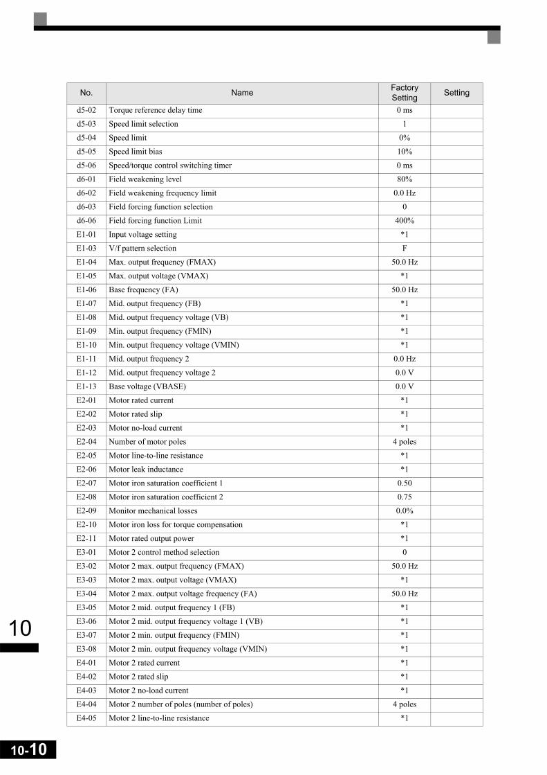
10-10
10
d5-02 Torque reference delay time 0 ms
d5-03 Speed limit selection 1
d5-04 Speed limit 0%
d5-05 Speed limit bias 10%
d5-06 Speed/torque control switching timer 0 ms
d6-01 Field weakening level 80%
d6-02 Field weakening frequency limit 0.0 Hz
d6-03 Field forcing function selection 0
d6-06 Field forcing function Limit 400%
E1-01 Input voltage setting *1
E1-03 V/f pattern selection F
E1-04 Max. output frequency (FMAX) 50.0 Hz
E1-05 Max. output voltage (VMAX) *1
E1-06 Base frequency (FA) 50.0 Hz
E1-07 Mid. output frequency (FB) *1
E1-08 Mid. output frequency voltage (VB) *1
E1-09 Min. output frequency (FMIN) *1
E1-10 Min. output frequency voltage (VMIN) *1
E1-11 Mid. output frequency 2 0.0 Hz
E1-12 Mid. output frequency voltage 2 0.0 V
E1-13 Base voltage (VBASE) 0.0 V
E2-01 Motor rated current *1
E2-02 Motor rated slip *1
E2-03 Motor no-load current *1
E2-04 Number of motor poles 4 poles
E2-05 Motor line-to-line resistance *1
E2-06 Motor leak inductance *1
E2-07 Motor iron saturation coefficient 1 0.50
E2-08 Motor iron saturation coefficient 2 0.75
E2-09 Monitor mechanical losses 0.0%
E2-10 Motor iron loss for torque compensation *1
E2-11 Motor rated output power *1
E3-01 Motor 2 control method selection 0
E3-02 Motor 2 max. output frequency (FMAX) 50.0 Hz
E3-03 Motor 2 max. output voltage (VMAX) *1
E3-04 Motor 2 max. output voltage frequency (FA) 50.0 Hz
E3-05 Motor 2 mid. output frequency 1 (FB) *1
E3-06 Motor 2 mid. output frequency voltage 1 (VB) *1
E3-07 Motor 2 min. output frequency (FMIN) *1
E3-08 Motor 2 min. output frequency voltage (VMIN) *1
E4-01 Motor 2 rated current *1
E4-02 Motor 2 rated slip *1
E4-03 Motor 2 no-load current *1
E4-04 Motor 2 number of poles (number of poles) 4 poles
E4-05 Motor 2 line-to-line resistance *1
No. Name FactorySetting Setting

10
E4-06 Motor 2 leak inductance *1
E4-07 Motor 2 rated capacity *1
F1-01 PG constant 1024
F1-02 Operation selection at PG open circuit (PGO) 1
F1-03 Operation selection at overspeed (OS) 1
F1-04 Operation selection at deviation 3
F1-05 PG rotation 0
F1-06 PG division rate (PG pulse monitor) 1
F1-07 Integral value during accel/decel enable/disable 0
F1-08 Overspeed detection level 115%
F1-09 Overspeed detection delay time 1.0 s
F1-10 Excessive speed deviation detection level 10%
F1-11 Excessive speed deviation detection delay time 0.5 s
F1-12 Number of PG gear teeth 1 0
F1-13 Number of PG gear teeth 2 0
F1-14 PG open-circuit detection delay time 2.0 s
F2-01 Bi-polar or uni-polar input selection 0
F3-01 Digital input option 0
F6-01 Operation selection after communications error 1
F6-02 Input level of external error from Communications Option Card 0
F6-03 Stopping method for external error from Communications Option Card 1
F6-04 Trace sampling from Communications Option Card 0
F6-05 Current monitor unit selection 1
F6-06 Torque reference/torque limit selection from communications option card 1
H1-01 Terminal S3 function selection 24
H1-02 Terminal S4 function selection 14
H1-03 Terminal S5 function selection 3 (0)*2
H1-04 Terminal S6 function selection 4 (3)*2
H1-05 Terminal S7 function selection 6 (4)*2
H2-01 Terminal M1-M2 function selection 0
H2-02 Terminal M3-M4 function selection 1
H2-03 Terminal M5-M6 function selection 2
H3-01 Multi-function analog input terminal A1 signal level selection 0
H3-02 Gain (terminal A1) 100.0%
H3-03 Bias (terminal A1) 0.0%
H3-08 Multi-function analog input terminal A2 signal level selection 2
H3-09 Multi-function analog input terminal A2 function selection 0
H3-10 Gain (terminal A2) 100.0%
H3-11 Bias (terminal A2) 0.0%
H3-12 Analog input filter time constant 0.00 s
H3-13 Terminal A1/A2 switching 0
H4-01 Monitor selection (terminal FM) 2
H4-02 Gain (terminal FM) 100%
H4-03 Bias (terminal FM) 0.0%
No. Name FactorySetting Setting
10-11

10-12
10
H4-04 Monitor selection (terminal AM) 3
H4-05 Gain (terminal AM) 50.0%
H4-06 Bias (terminal AM) 0.0%
H4-07 Analog output 1 signal level selection 0
H4-08 Analog output 2 signal level selection 0
H5-01 Station address 1F
H5-02 Communications speed selection 3
H5-03 Communications parity selection 0
H5-04 Stopping method after communications error 3
H5-05 Communications error detection selection 1
H5-06 Send wait time 5 ms
H5-07 RTS control ON/OFF 1
H6-01 Pulse train input function selection 0
H6-02 Pulse train input scaling 1440 Hz
H6-03 Pulse train input gain 100.0%
H6-04 Pulse train input bias 0.0%
H6-05 Pulse train input filter time 0.10 s
H6-06 Pulse train monitor selection 2
H6-07 Pulse train monitor scaling 1440 Hz
L1-01 Motor protection selection 1
L1-02 Motor protection time constant 1.0 min
L1-03 Alarm operation selection during motor overheating 3
L1-04 Motor overheating operation selection 1
L1-05 Motor temperature input filter time constant 0.20 s
L2-01 Momentary power loss detection 0
L2-02 Momentary power loss ride through time *1
L2-03 Min. baseblock time *1
L2-04 Voltage recovery time *1
L2-05 Undervoltage detection level *1
L2-06 KEB deceleration time 0.0 s
L2-07 Momentary recovery time *1
L2-08 Frequency reduction gain at KEB start 100%
L3-01 Stall prevention selection during accel 1
L3-02 Stall prevention level during accel 150%
L3-03 Stall prevention limit during accel 50%
L3-04 Stall prevention selection during decel 1
L3-05 Stall prevention selection during running 1
L3-06 Stall prevention level during running 150%
L4-01 Speed agreement detection level 0.0 Hz
L4-02 Speed agreement detection width 2.0 Hz
L4-03 Speed agreement detection level (+/-) 0.0 Hz
L4-04 Speed agreement detection width (+/-) 2.0 Hz
L4-05 Operation when frequency reference is missing 0
L4-06 Frequency reference value at frequency reference loss 80%
L5-01 Number of auto restart attempts 0
No. Name FactorySetting Setting

10
L5-02 Auto restart operation selection 0
L6-01 Torque detection selection 1 0
L6-02 Torque detection level 1 150%
L6-03 Torque detection time 1 0.1 s
L6-04 Torque detection selection 2 0
L6-05 Torque detection level 2 150%
L6-06 Torque detection time 2 0.1 s
L7-01 Forward drive torque limit 200%
L7-02 Reverse drive torque limit 200%
L7-03 Forward regenerative torque limit 200%
L7-04 Reverse regenerative torque limit 200%
L7-06 Torque limit time constant 200 ms
L7-07 Torque Limit Operation during accel/decel 0
L8-01 Protect selection for internal DB resistor (Type ERF) 0
L8-02 Overheat pre-alarm level 95 °C*1
L8-03 Operation selection after overheat pre-alarm 3
L8-05 Input open-phase protection selection 1
L8-07 Output open-phase protection selection 0
L8-09 Ground protection selection 1
L8-10 Cooling fan control selection 0
L8-11 Cooling fan control delay time 60 s
L8-12 Ambient temperature 45 °C
L8-15 OL2 characteristics selection at low speeds 1
L8-18 Soft CLA selection 1
N1-01 Hunting-prevention function selection 1
N1-02 Hunting-prevention gain 1.00
N2-01 Speed feedback detection control (AFR) gain 1.00
N2-02 Speed feedback detection control (AFR) time constant 50 ms
N2-03 Speed feedback detection control (AFR) time constant 2 750 ms
N3-01 High-slip braking deceleration frequency width 5%
N3-02 High-slip braking current limit 150%
N3-03 High-slip braking stop dwell time 1.0 s
N3-04 High-slip braking OL time 40 s
o1-01 Monitor selection 6
o1-02 Monitor selection after power up 1
o1-03 Frequency units of reference setting and monitor 0
o1-04 Setting unit for frequency parameters related to V/f characteristics 0
o1-05 LCD Display contrast adjustment 3
o2-01 LOCAL/REMOTE key enable/disable 1
o2-02 STOP key during control circuit terminal operation 1
o2-03 User parameter initial value 0
o2-04 kVA selection 0
o2-05 Frequency reference setting method selection 0
o2-06 Operation selection when digital operator is disconnected 0
o2-07 Cumulative operation time setting 0 hr
No. Name FactorySetting Setting
10-13

10-14
10
* 1. The factory setting depends on the inverter model and the control method.* 2. The values in parentheses indicate initial values when initialized in 3-wire sequence.
o2-08 Cumulative operation time selection 0
o2-09 Initialize Mode 2
o2-10 Fan operation time setting 0 hr
o2-12 Fault trace initialize 0
o2-13 kWh monitor initialize 0
o3-01 Copy function selection 0
o3-02 Read permission selection 0
T1-00 Motor 1/2 selection 1
T1-01 Autotuning mode selection 0
T1-02 Motor output power *1
T1-03 Motor rated voltage *1
T1-04 Motor rated current *1
T1-05 Motor base frequency 50.0 Hz
T1-06 Number of motor poles 4 poles
T1-07 Motor base speed 1450 r/min
T1-08 Number of PG pulses 1024
No. Name FactorySetting Setting