various descriptions of majority gate when-else if-else case, select and other conditionals in...
TRANSCRIPT

• Various Descriptions of Majority Gate
• When-else
• If-else
• Case, select and other conditionals in sequential and concurrent descriptions
• Concurrent Statements versus Processes
• Priority Circuits and Multiplexers
• Ripple Carry Adders
Introduction To Introduction To VHDL for VHDL for
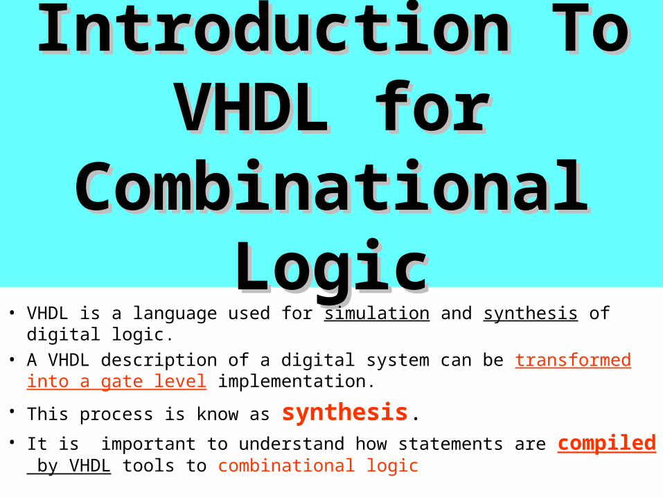
Combinational LogicCombinational Logic• VHDL is a language used for simulation and synthesis of digital logic.
• A VHDL description of a digital system can be transformed into a gate level implementation.
• This process is know as synthesis.• It is important to understand how statements are compiled by VHDL
tools to combinational logic
VHDL has two semantics
1. Semantics for simulation
2. Semantics for synthesis
Concurrent Concurrent Statements in Statements in
VHDLVHDL
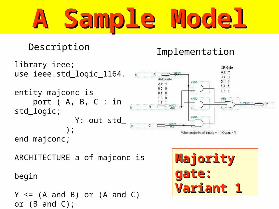
library ieee;use ieee.std_logic_1164.all;
entity majconc is port ( A, B, C : in std_logic; Y: out std_logic );end majconc;
ARCHITECTURE a of majconc is
begin
Y <= (A and B) or (A and C) or (B and C);end a;
A Sample ModelA Sample ModelDescription Implementation
Majority gate: Majority gate: Variant 1Variant 1
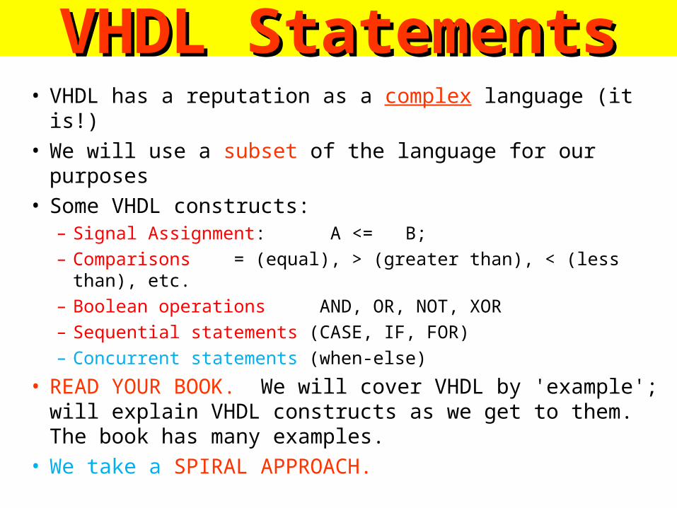
VHDL StatementsVHDL Statements• VHDL has a reputation as a complex language (it is!)• We will use a subset of the language for our purposes• Some VHDL constructs:
– Signal Assignment: A <= B;
– Comparisons = (equal), > (greater than), < (less than), etc.
– Boolean operations AND, OR, NOT, XOR
– Sequential statements (CASE, IF, FOR)
– Concurrent statements (when-else)
• READ YOUR BOOK. We will cover VHDL by 'example'; will explain VHDL constructs as we get to them. The book has many examples.
• We take a SPIRAL APPROACH.
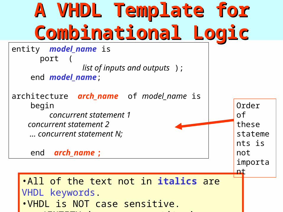
A VHDL Template for A VHDL Template for Combinational LogicCombinational Logic
entity model_name is port ( list of inputs and outputs ); end model_name; architecture arch_name of model_name is begin concurrent statement 1 concurrent statement 2 ... concurrent statement N;
end arch_name ;
•All of the text not in italics are VHDL keywords. •VHDL is NOT case sensitive.
•(ENTITY is same as entity is same as EnTiTy).
Order of these statements is not important
Majority Majority Gate Gate
ExampleExample

Majority Gate ExampleMajority Gate ExampleThe following is an example of a three input XOR gate (majority gate) implemented in VHDL
library ieee;use ieee.std_logic_1164.all;
entity majority is port ( A, B, C : in std_logic; -- two dashes is a COMMENT in VHDL Y: out std_logic );end majority;-- this is the architecture declaration, uses only one concurrent statement.
ARCHITECTURE concurrent of majority is
begin
Y <= (A and B) or (A and C) or (B and C);end concurrent;
This is a style of This is a style of one big expressionone big expression
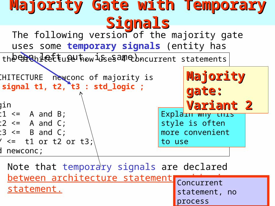
Majority Gate with Temporary SignalsMajority Gate with Temporary SignalsThe following version of the majority gate uses some temporary signals (entity has been left out, is same).
-- the architecture now uses 4 concurrent statements
ARCHITECTURE newconc of majority is signal t1, t2, t3 : std_logic ;
begin t1 <= A and B; t2 <= A and C; t3 <= B and C; Y <= t1 or t2 or t3;end newconc;
Note that temporary signals are declared between architecture statement and begin statement.
Signals cannot be declared in a process.
Explain why this style is often more convenient to use
Majority gate: Majority gate: Variant 2Variant 2
Concurrent statement, no process
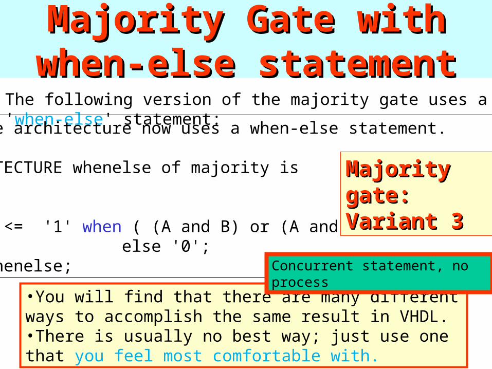
Majority Gate with when-else Majority Gate with when-else statementstatement
The following version of the majority gate uses a 'when-else' statement:
-- the architecture now uses a when-else statement.
ARCHITECTURE whenelse of majority is
begin Y <= '1' when ( (A and B) or (A and C) or (B and C)) else '0';end whenelse;
•You will find that there are many different ways to accomplish the same result in VHDL. •There is usually no best way; just use one that you feel most comfortable with.
Majority gate: Majority gate: Variant 3Variant 3
Concurrent statement, no process
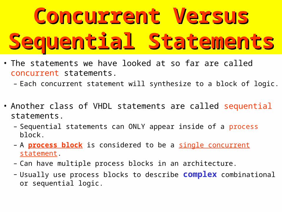
Concurrent Versus Sequential Concurrent Versus Sequential StatementsStatements
• The statements we have looked at so far are called concurrent statements.– Each concurrent statement will synthesize to a block of logic.
• Another class of VHDL statements are called sequential statements.– Sequential statements can ONLY appear inside of a process block. – A process block is considered to be a single concurrent statement.– Can have multiple process blocks in an architecture.
– Usually use process blocks to describe complex combinational or sequential logic.
RememberRemember
A process block is considered to be a single concurrent statement.
Majority Gate using Majority Gate using processprocess block and block and ifif
statementstatement
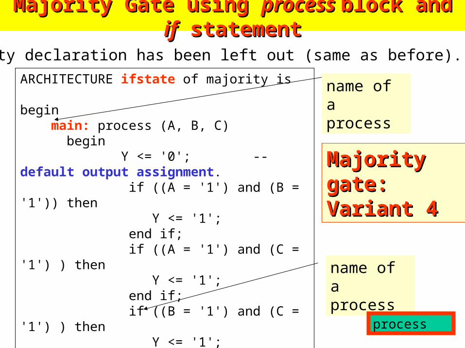
Majority Gate using Majority Gate using process process block and block and ifif statement statement
The entity declaration has been left out (same as before).
ARCHITECTURE ifstate of majority is
begin main: process (A, B, C) begin Y <= '0'; -- default output assignment. if ((A = '1') and (B = '1')) then Y <= '1'; end if; if ((A = '1') and (C = '1') ) then Y <= '1'; end if; if ((B = '1') and (C = '1') ) then Y <= '1'; end if; end process main;end ifstate;
name of a process
name of a process
Majority gate: Majority gate: Variant 4Variant 4
process
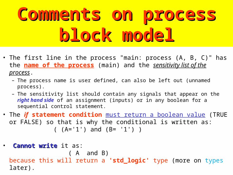
Comments on process block Comments on process block modelmodel
• The first line in the process "main: process (A, B, C)" has the name of the process (main) and the sensitivity list of the process.– The process name is user defined, can also be left out (unnamed process).
– The sensitivity list should contain any signals that appear on the right hand side of an assignment (inputs) or in any boolean for a sequential control statement.
• The if statement condition must return a boolean value (TRUE or FALSE) so that is why the conditional is written as: ( (A='1') and (B= '1') )
• Cannot writeCannot write it as: ( A and B)because this will return a 'std_logic' type (more on types later).
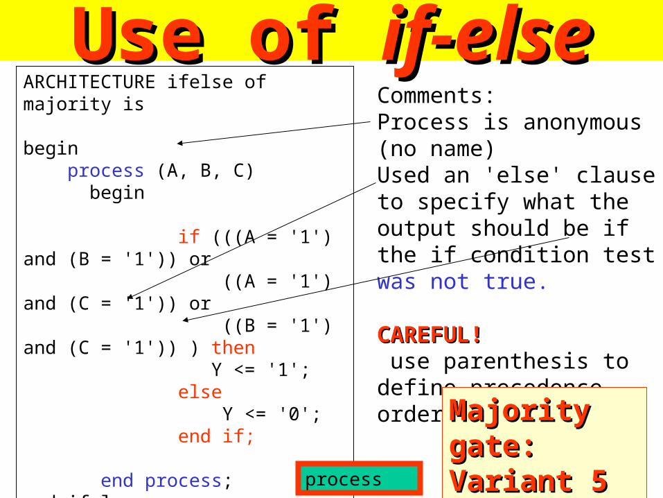
Use of Use of if-elseif-elseARCHITECTURE ifelse of majority is
begin process (A, B, C) begin if (((A = '1') and (B = '1')) or ((A = '1') and (C = '1')) or ((B = '1') and (C = '1')) ) then Y <= '1'; else Y <= '0'; end if;
end process;end ifelse;
Comments:Process is anonymous (no name)Used an 'else' clause to specify what the output should be if the if condition test was not true.
CAREFUL!CAREFUL! use parenthesis to define precedence order
Majority gate: Majority gate: Variant 5Variant 5
process
Unassigned Unassigned outputsoutputs in in
Process blocksProcess blocks
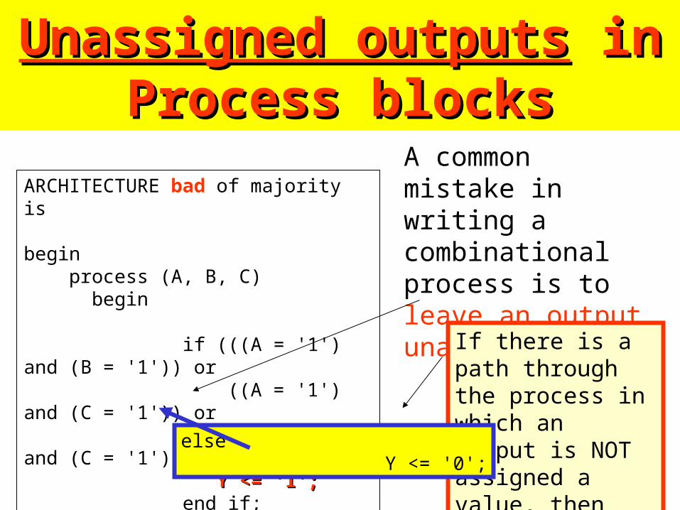
Unassigned outputsUnassigned outputs in Process in Process blocksblocks
A common mistake in writing a combinational process is to leave an output unassigned.
ARCHITECTURE bad of majority is
begin process (A, B, C) begin if (((A = '1') and (B = '1')) or ((A = '1') and (C = '1')) or ((B = '1') and (C = '1')) ) then Y <= '1';Y <= '1'; end if;
end process;end bad;
If there is a path through the process in which an output is NOT assigned a value, then that value is unassigned.
else Y <= '0';
Please remember
You will regret if you forget to leave an output unassigned.
Please rememberI can sleep well when my students follow my morals.
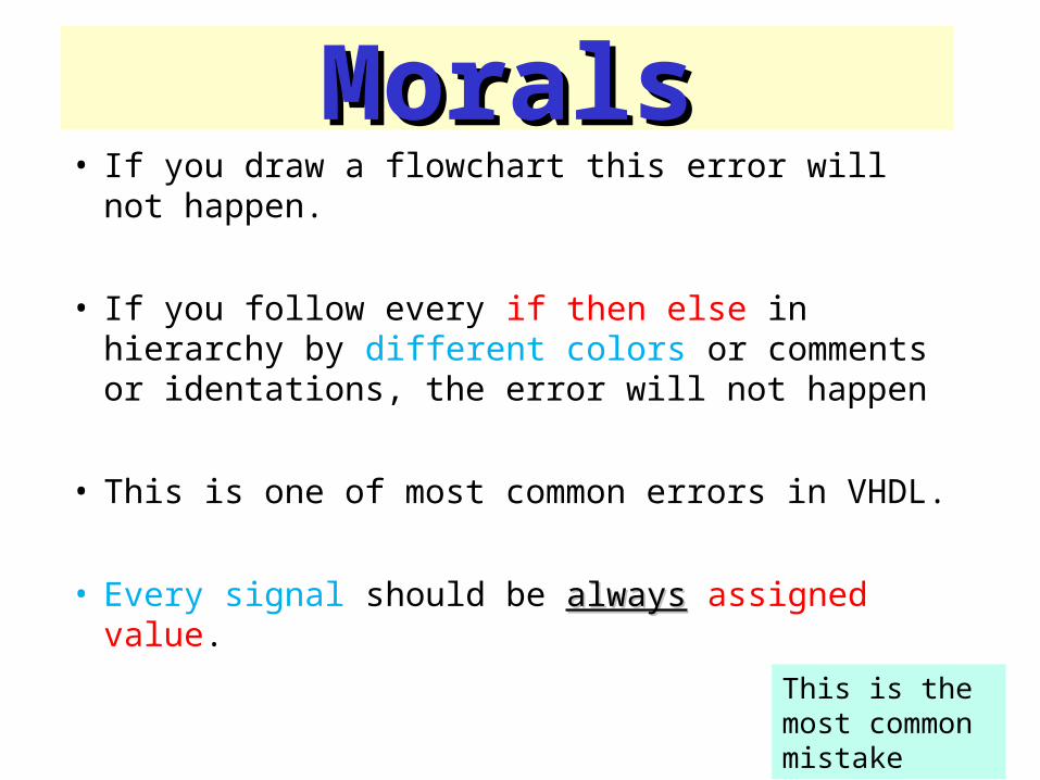
MoralsMorals• If you draw a flowchart this error will not happen.
• If you follow every if then else in hierarchy by different colors or comments or identations, the error will not happen
• This is one of most common errors in VHDL.
• Every signal should be alwaysalways assigned value.
This is the most common mistake
More Comments on ‘bad’ architectureMore Comments on ‘bad’ architecture
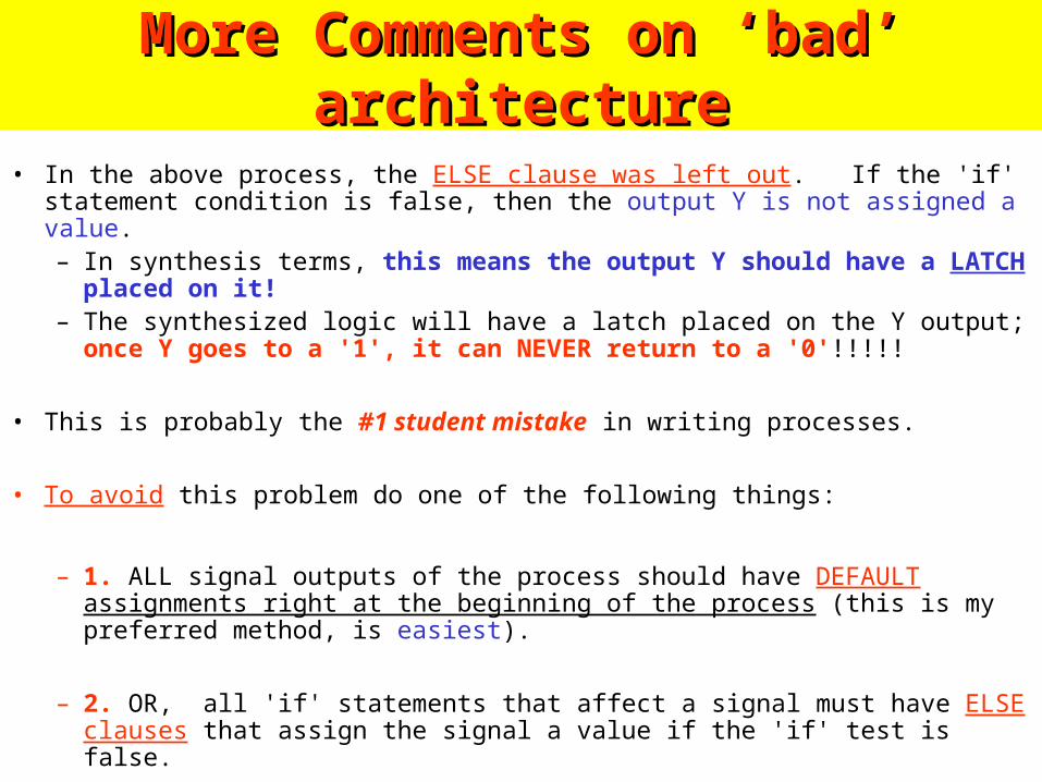
• In the above process, the ELSE clause was left out. If the 'if' statement condition is false, then the output Y is not assigned a value.– In synthesis terms, this means the output Y should have a LATCH placed on
it!– The synthesized logic will have a latch placed on the Y output; once Y goes to
a '1', it can NEVER return to a '0'!!!!!
• This is probably the #1 student mistake in writing processes.
• To avoid this problem do one of the following things:
– 1. ALL signal outputs of the process should have DEFAULT assignments right at the beginning of the process (this is my preferred method, is easiest).
– 2. OR, all 'if' statements that affect a signal must have ELSE clauses that assign the signal a value if the 'if' test is false.

Priority Priority circuit circuit
exampleexample
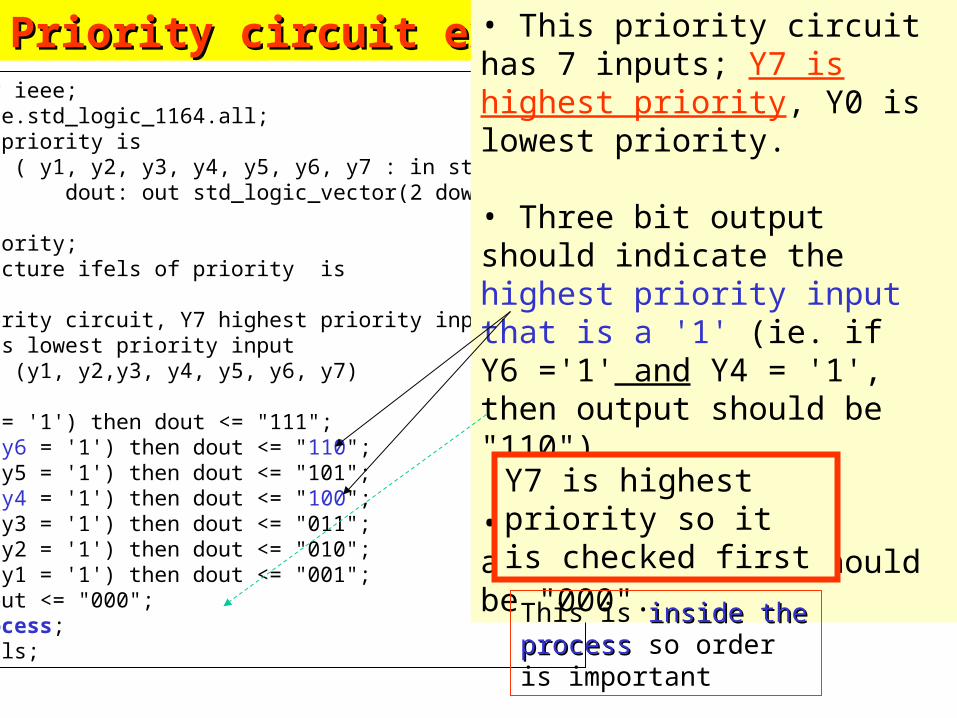
library ieee;use ieee.std_logic_1164.all;entity priority is port ( y1, y2, y3, y4, y5, y6, y7 : in std_logic; dout: out std_logic_vector(2 downto 0) );end priority;architecture ifels of priority isbegin-- priority circuit, Y7 highest priority input-- Y1 is lowest priority inputprocess (y1, y2,y3, y4, y5, y6, y7)beginif (y7 = '1') then dout <= "111";elsif (y6 = '1') then dout <= "110";elsif (y5 = '1') then dout <= "101";elsif (y4 = '1') then dout <= "100";elsif (y3 = '1') then dout <= "011";elsif (y2 = '1') then dout <= "010";elsif (y1 = '1') then dout <= "001";else dout <= "000";end process;end ifels;
Priority circuit examplePriority circuit example • This priority circuit has 7 inputs; Y7 is highest priority, Y0 is lowest priority.
• Three bit output should indicate the highest priority input that is a '1' (ie. if Y6 ='1' and Y4 = '1', then output should be "110"). •If no input is asserted, output should be "000".
Y7 is highest priority so it is checked first
This is inside the processinside the process so order is important
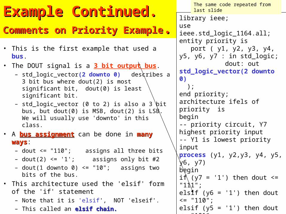
Example Continued.Example Continued.Comments on Priority ExampleComments on Priority Example..• This is the first example that used a bus.
• The DOUT signal is a 3 bit output bus.– std_logic_vector(2 downto 0) describes a 3 bit
bus where dout(2) is most significant bit, dout(0) is least significant bit.
– std_logic_vector (0 to 2) is also a 3 bit bus, but dout(0) is MSB, dout(2) is LSB. We will usually use 'downto' in this class.
• A bus assignmentbus assignment can be done in many waysmany ways:– dout <= "110"; assigns all three bits
– dout(2) <= '1'; assigns only bit #2
– dout(1 downto 0) <= "10"; assigns two bits of the bus.
• This architecture used the 'elsif' form of the 'if' statement– Note that it is 'elsif', NOT 'elseif'.
– This called an elsif chain.elsif chain.
library ieee;use ieee.std_logic_1164.all;entity priority is port ( y1, y2, y3, y4, y5, y6, y7 : in std_logic; dout: out std_logic_vector(2 downto 0) );end priority;architecture ifels of priority isbegin-- priority circuit, Y7 highest priority input-- Y1 is lowest priority inputprocess (y1, y2,y3, y4, y5, y6, y7)beginif (y7 = '1') then dout <= "111";elsif (y6 = '1') then dout <= "110";elsif (y5 = '1') then dout <= "101";elsif (y4 = '1') then dout <= "100";elsif (y3 = '1') then dout <= "011";elsif (y2 = '1') then dout <= "010";elsif (y1 = '1') then dout <= "001";else dout <= "000";end process;end ifels;
The same code repeated from last slide

New VariantNew Variant: Priority Circuit : Priority Circuit with just IF statements.with just IF statements.
architecture plainif of priority isbegin-- priority circuit, Y7 highest priority input-- Y1 is lowest priority inputprocess (y1, y2,y3, y4, y5, y6, y7)begindout <= "000;if (y1 = '1') then dout <= "001"; end if;if (y2 = '1') then dout <= "010"; end if;if (y3 = '1') then dout <= "011"; end if;if (y4 = '1') then dout <= "100"; end if;if (y5 = '1') then dout <= "101"; end if;if (y6 = '1') then dout <= "110"; end if;if (y7 = '1') then dout <= "111"; end if;end process;end plainif;
By reversing the order of the assignments, we can accomplish the same as the elsif priority chain.
In a process, the LAST In a process, the LAST assignment to the output is assignment to the output is what counts.what counts.
Y7 is highest priority so it is checked lastchecked last
Because in process the last the last value assigned wins!!value assigned wins!!
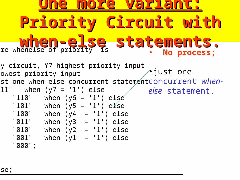
One more variant:One more variant: Priority Priority Circuit with when-else statements.Circuit with when-else statements.architecture whenelse of priority isbegin-- priority circuit, Y7 highest priority input-- Y1 is lowest priority input-- uses just one when-else concurrent statement.dout <= "111" when (y7 = '1') else "110" when (y6 = '1') else "101" when (y5 = '1') else "100" when (y4 = '1') else "011" when (y3 = '1') else "010" when (y2 = '1') else "001" when (y1 = '1') else "000";
end whenelse;
• No process; •just one concurrent when-else statement.
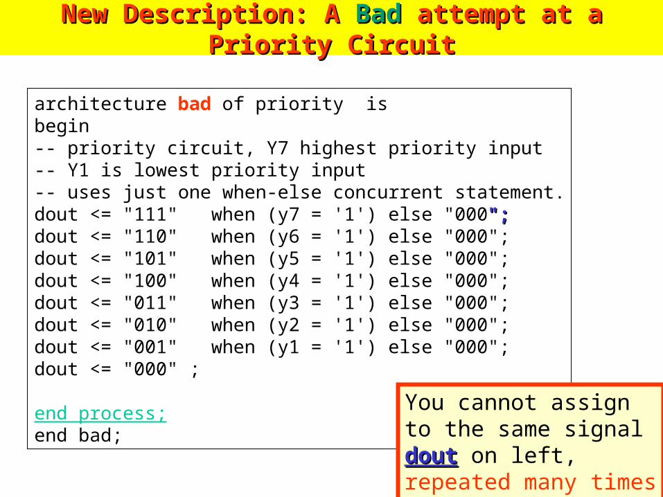
New Description: A New Description: A BadBad attempt at a Priority Circuit attempt at a Priority Circuit
architecture bad of priority isbegin-- priority circuit, Y7 highest priority input-- Y1 is lowest priority input-- uses just one when-else concurrent statement.dout <= "111" when (y7 = '1') else "000";";dout <= "110" when (y6 = '1') else "000";dout <= "101" when (y5 = '1') else "000";dout <= "100" when (y4 = '1') else "000";dout <= "011" when (y3 = '1') else "000";dout <= "010" when (y2 = '1') else "000";dout <= "001" when (y1 = '1') else "000";dout <= "000" ;
end process;end bad;
You cannot assign to the same signal doutdout on left, repeated many times in concurrent statements!!
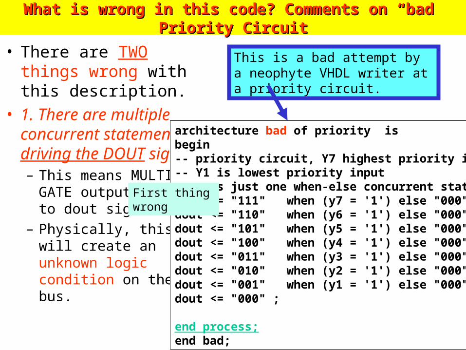
What is wrong in this code? Comments on “bad” Priority CircuitWhat is wrong in this code? Comments on “bad” Priority Circuit
• There are TWO things wrong with this description.
• 1. There are multiple concurrent statements driving the DOUT signal. – This means MULTIPLE
GATE output are tied to dout signal!
– Physically, this will create an unknown logic condition on the bus.
architecture bad of priority isbegin-- priority circuit, Y7 highest priority input-- Y1 is lowest priority input-- uses just one when-else concurrent statement.dout <= "111" when (y7 = '1') else "000";dout <= "110" when (y6 = '1') else "000";dout <= "101" when (y5 = '1') else "000";dout <= "100" when (y4 = '1') else "000";dout <= "011" when (y3 = '1') else "000";dout <= "010" when (y2 = '1') else "000";dout <= "001" when (y1 = '1') else "000";dout <= "000" ;
end process;end bad;
This is a bad attempt by a neophyte VHDL writer at a priority circuit.
First thing wrong
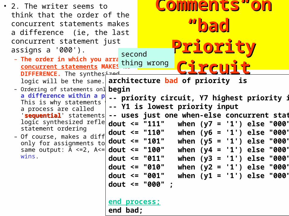
Comments on Comments on “bad” Priority “bad” Priority
CircuitCircuit
• 2. The writer seems to think that the order of the concurrent statements makes a difference (ie, the last concurrent statement just assigns a '000'). – The order in which you
arrange concurrent statements MAKES NO DIFFERENCE. The synthesized logic will be the same.
– Ordering of statements only makes a difference within a process. This is why statements within a process are called 'sequentialsequential' statements; the logic synthesized reflects the statement ordering
– Of course, makes a difference only for assignments to the same output: A <=2, A<=3, last wins.
architecture bad of priority isbegin-- priority circuit, Y7 highest priority input-- Y1 is lowest priority input-- uses just one when-else concurrent statement.dout <= "111" when (y7 = '1') else "000";dout <= "110" when (y6 = '1') else "000";dout <= "101" when (y5 = '1') else "000";dout <= "100" when (y4 = '1') else "000";dout <= "011" when (y3 = '1') else "000";dout <= "010" when (y2 = '1') else "000";dout <= "001" when (y1 = '1') else "000";dout <= "000" ;
end process;end bad;
second thing wrong
4-to-1 mux with 4-to-1 mux with 8 bit Datapaths8 bit Datapaths

NEW EXAMPLENEW EXAMPLE: 4-to-1 mux with 8 : 4-to-1 mux with 8 bit Datapathsbit Datapaths
library ieee;use ieee.std_logic_1164.all;entity mux4to1_8 is port ( a,b,c,d : in std_logic_vector(7 downto 0); sel: in std_logic_vector (1 downto 0); dout: out std_logic_vector(7 downto 0) );end mux4to1_8;architecture whenelse of mux4to1_8 isbegindout <= b when (sel = "01") else c when (sel = "10") else d when (sel = "11") else a; -- default
end process;end whenelse;
8
sel
We do not use with in this example
dout8
2
a b c d
0 1 2 3
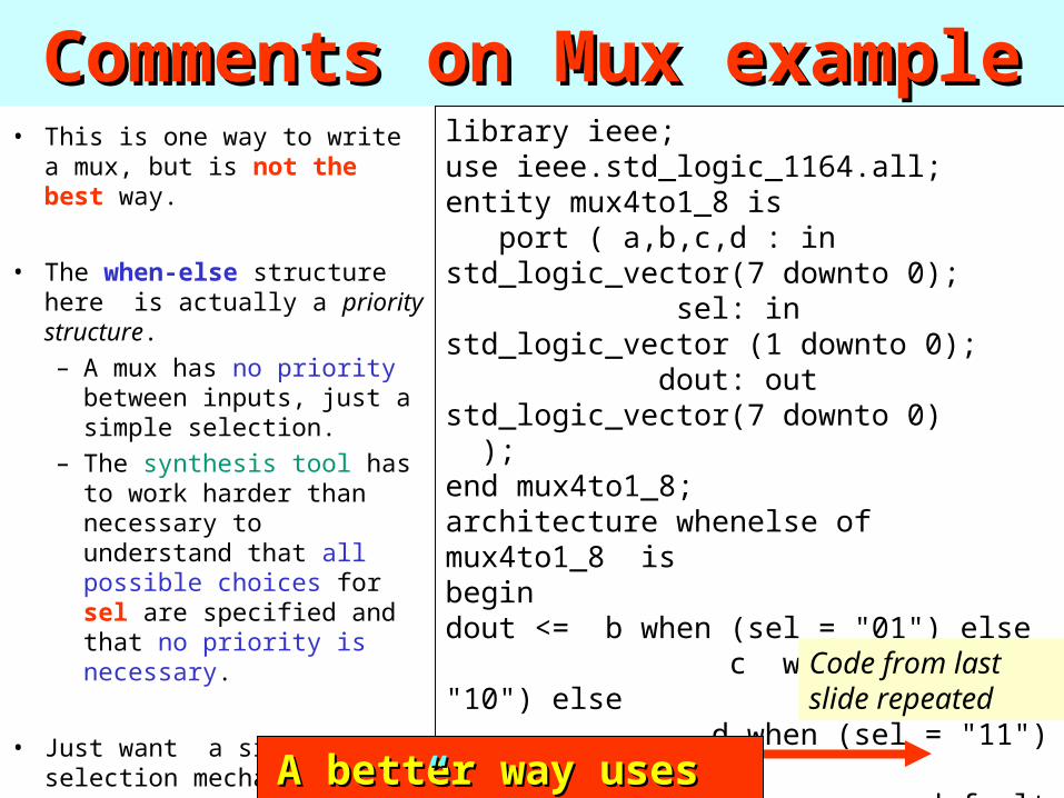
Comments on Mux exampleComments on Mux example• This is one way to write a
mux, but is not the best way.
• The when-else structure here is actually a priority structure.
– A mux has no priority between inputs, just a simple selection.
– The synthesis tool has to work harder than necessary to understand that all possible choices for sel are specified and that no priority is necessary.
• Just want a simple selection mechanism.
library ieee;use ieee.std_logic_1164.all;entity mux4to1_8 is port ( a,b,c,d : in std_logic_vector(7 downto 0); sel: in std_logic_vector (1 downto 0); dout: out std_logic_vector(7 downto 0) );end mux4to1_8;architecture whenelse of mux4to1_8 isbegindout <= b when (sel = "01") else c when (sel = "10") else d when (sel = "11") else a; -- default
end process;end whenelse;
A better way uses “A better way uses “with”with”
Code from last slide repeated

4-to-1 Mux using 4-to-1 Mux using SelectSelect Concurrent Concurrent StatementStatement
architecture select_statement of mux4to1_8 isbeginwith sel selectselect dout <= b when "01", c when "10", d when "11", a when others;end select_statementselect_statement;
• Some synthesis tools will automatically recognize this structure (using with) as a muxmux•They will find a more efficient implementation than using a when-else or if statement structure • Remember in general that when-else and if structures define priority priority structures for compilationstructures for compilation.
8
sel
dout82
a b c d
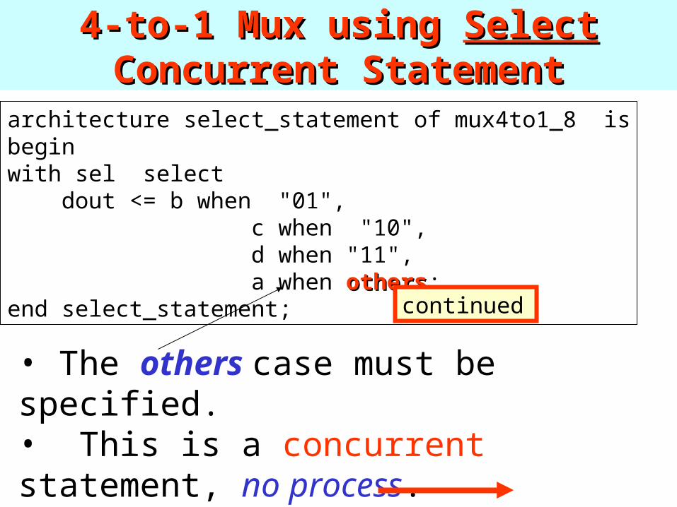
4-to-1 Mux using 4-to-1 Mux using SelectSelect Concurrent Concurrent StatementStatement
architecture select_statement of mux4to1_8 isbeginwith sel select dout <= b when "01", c when "10", d when "11", a when othersothers;end select_statement;
• The others case must be specified.• This is a concurrent statement, no process.• The sequential version of the select statement is the case statement.
continued
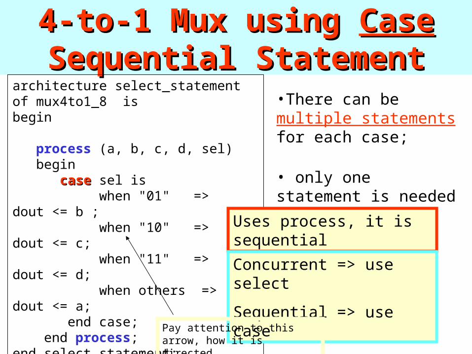
4-to-1 Mux using 4-to-1 Mux using CaseCase Sequential Sequential StatementStatement
architecture select_statement of mux4to1_8 isbegin
process (a, b, c, d, sel) begin casecase sel is when "01" => dout <= b ; when "10" => dout <= c; when "11" => dout <= d; when others => dout <= a; end case; end process;end select_statement;
•There can be multiple statements for each case;
• only one statement is needed for each case in this example.
Uses process, it is sequential
Concurrent => use select
Sequential => use case
Pay attention to this arrow, how it is directed
Logical Shift Logical Shift Left by 1Left by 1
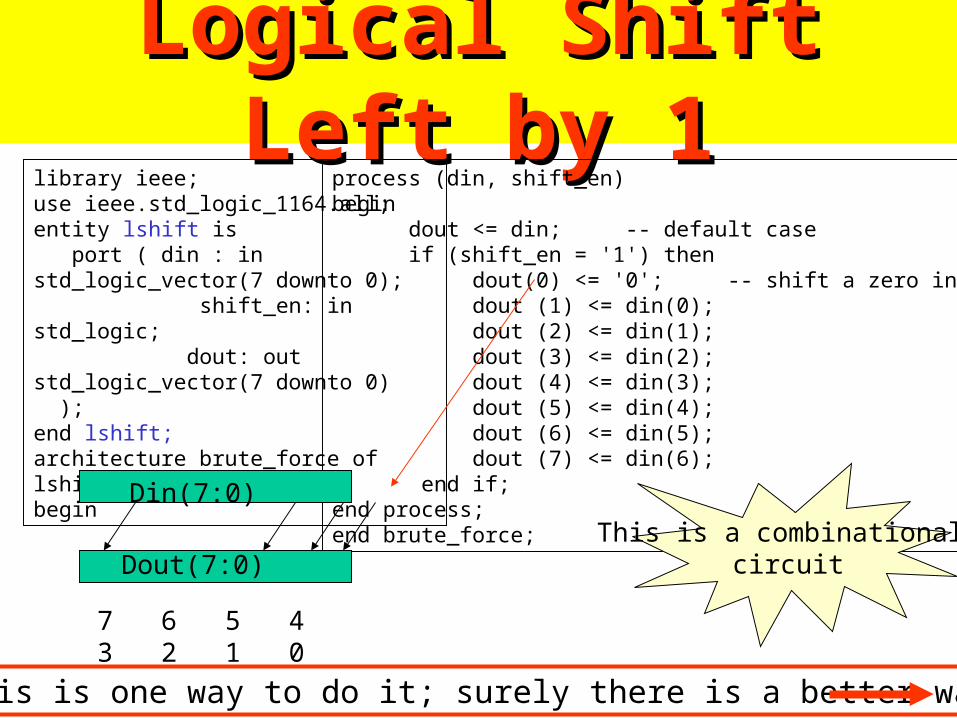
Logical Shift Left by 1Logical Shift Left by 1library ieee;use ieee.std_logic_1164.all;entity lshift is port ( din : in std_logic_vector(7 downto 0); shift_en: in std_logic; dout: out std_logic_vector(7 downto 0) );end lshift;architecture brute_force of lshift isbegin
process (din, shift_en)begin dout <= din; -- default case if (shift_en = '1') then dout(0) <= '0'; -- shift a zero into LSB dout (1) <= din(0); dout (2) <= din(1); dout (3) <= din(2); dout (4) <= din(3); dout (5) <= din(4); dout (6) <= din(5); dout (7) <= din(6); end if; end process;end brute_force;
This is one way to do it; surely there is a better way?
Din(7:0)
Dout(7:0)
7 6 5 4 3 2 1 0
This is a combinational circuit
Logical Shift Left by 1 (better way)Logical Shift Left by 1 (better way)
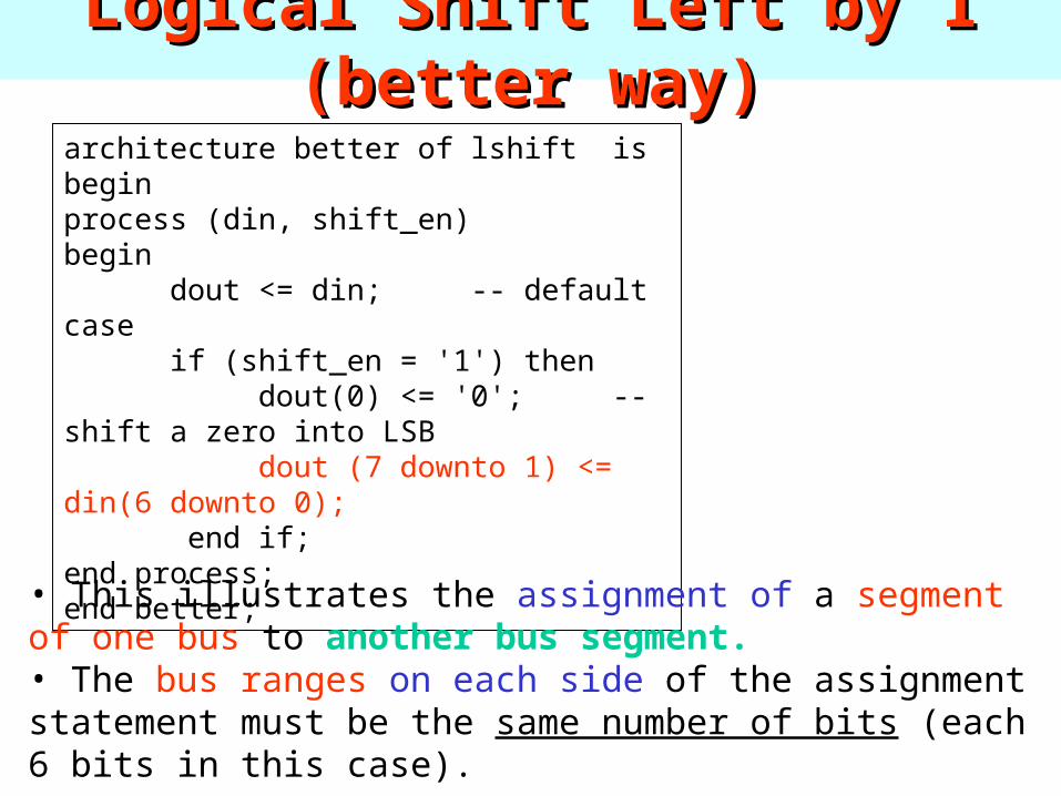
architecture better of lshift isbeginprocess (din, shift_en)begin dout <= din; -- default case if (shift_en = '1') then dout(0) <= '0'; -- shift a zero into LSB dout (7 downto 1) <= din(6 downto 0); end if; end process;end better;
• This illustrates the assignment of a segment of one bus to another bus segment. • The bus ranges on each side of the assignment statement must be the same number of bits (each 6 bits in this case).

4 Bit Ripple 4 Bit Ripple Carry AdderCarry Adder

4 Bit Ripple Carry Adder4 Bit Ripple Carry Adder
A B
S
CiCo
A B
S
CiCo
A B
S
CiCo
A B
S
CiCo Cin
A(0)
Cout
B(0)A(1) B(1)A(2) B(2)A(3) B(3)
C(0)C(1)C(2)C(3)C(4)
Sum(0)Sum(1)Sum(2)Sum(3)
Want to write a VHDL model for a 4 bit ripple carry adder. Logic equation for each full adder is: sum <= a xor b xor ci; co <= (a and b) or (ci and (a or b));
• We used GENERATE before to describe this circuit• Now we will do this withoutwithout GENERATE

4 Bit Ripple Carry Model 4 Bit Ripple Carry Model library ieee;use ieee.std_logic_1164.all;entity adder4bit is port ( a,b: in std_logic_vector(3 downto 0); cin : in std_logic; cout: out std_logic; sum: out std_logic_vector(3 downto 0) );end adder4bit;architecture bruteforce of adder4bit is -- temporary signals for internal carries signal c : std_logic_vector(4 downto 0); .begin process (a, b, cin, c) begin c(0) <= cin; -- full adder 0 sum(0) <= a(0) xor b(0) xor c(0); c(1) <= (a(0) and b(0)) or (c(0) and (a(0) or b(0))); -- full adder 1 sum(1) <= a(1) xor b(1) xor c(1); c(2) <= (a(1) and b(1)) or (c(1) and (a(1) or b(1)));
-- full adder 2 sum(2) <= a(2) xor b(2) xor c(2); c(3) <= (a(2) and b(2)) or (c(2) and (a(2) or b(2))); -- full adder 3 sum(3) <= a(3) xor b(3) xor c(3); c(4) <= (a(3) and b(3)) or (c(3) and (a(3) or b(3))); cout <= c(4);end process;end bruteforce;
•Straight forward Straight forward implementation. implementation.
•Nothing wrong with Nothing wrong with this.this.
•However, is there an However, is there an easiereasier way?way?
Not very elegant for long words, not scalable

4 Bit Ripple Carry Model 4 Bit Ripple Carry Model using using For For StatementStatement
architecture forloop of adder4bit is
signal c : std_logic_vector(4 downto 0); -- temporary signals for internal carries.begin process (a, b, cin, c) begin c(0) <= cin; for i in 0 to 3 loop -- all four full adders sum(i) <= a(i) xor b(i) xor c(i); c(i+1) <= (a(i) and b(i)) or (c(i) and (a(i) or b(i))); end loop; cout <= c(4); end process;end forloop;
Index “i” is not a signal , not a variable.
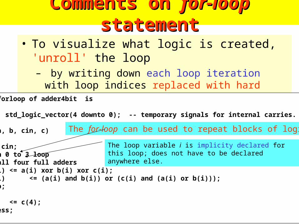
Comments on Comments on for-loop for-loop statementstatement
• To visualize what logic is created, 'unroll' the loop– by writing down each loop iteration with loop indices
replaced with hard numbers.
architecture forloop of adder4bit is
signal c : std_logic_vector(4 downto 0); -- temporary signals for internal carries.begin process (a, b, cin, c) begin c(0) <= cin; for i in 0 to 3 loop -- all four full adders sum(i) <= a(i) xor b(i) xor c(i); c(i+1) <= (a(i) and b(i)) or (c(i) and (a(i) or b(i))); end loop; cout <= c(4); end process;end forloop;
The for-loop can be used to repeat blocks of logic
The loop variable i is implicity declared for this loop; does not have to be declared anywhere else.
SummarySummary• There are many different ways to write VHDL synthesizable models for synthesizable models for
combinational logic.combinational logic.
• There is no 'best' way to write a model; for now, just use the statements/style that you feel most comfortable with and can get to work (of course!)
• READ THE BOOK!!!!!!!!
– There is NO WAY that we can cover all possible examples in class. The book has many other VHDL examples.
– I have intentionally left out MANY, MANY language details.
– You can get by with what I have shown you, but feel free to experiment with other language features that you see discussed in the book or elsewhere.
Summary (cont.)Summary (cont.)• SEARCH THE WWW!!!!!
– The WWW is full of VHDL examples, tutorials, etc.
• TRY IT OUT!!!!– If you have a question about a statement or example, try it out in the Altera Maxplus package
and see what happens!
• This course is about Digital System DESIGN, not VHDL language itself. – As such, we will have only some lectures about VHDL,
• the rest will be on design topics.
– VHDL is only a means for efficiently implementing your design - it is not interesting by itself.
– You will probably learn multiple synthesis languages in your design career - it is the digital design techniques that you use that will be common to your designs, not the synthesis language.
For students to remember and use in For students to remember and use in their worktheir work
• Templates for combinational design– How to describe majority in different waysmajority in different ways
• Use of if else in combinational logic• Use of if else in state machines
• Description of various types of multiplexers.• Basic design constructs:
– Case– Select– When– For and loop
• Understand why latches can be incorrectly created from your description while you do not desire them.
Remark on where we are in class?Remark on where we are in class?• At this time we have shown the following pieces of knowledge:
– 1. How to design combinational circuits of various types– 2. How to design sequential circuits of various types– 3. How to describe them in VHDL
• Now you have enough knowledge to solve Homework 1 and Homework 2.
• To be able to design a large circuit in project you need however more knowledge, in the given below priorities
– A) computer architecture and the methods to design high-performance DSP and Image Processing circuits.
– B) Pipelining, systolic design, etc.– C) More on VHDL simulation and synthesis, how the CAD tools work.– D) more on building testbenches.

SourcesSources• Bob Reese
• Students from previous classes