variax 2 plating systems - stryker meded · the anchorage 2 cp system is intended for use in...
TRANSCRIPT

Operative techniqueAnchorage® 2 CP
VariAx® 2 Plating Systems

2
This publication sets forth detailed recommended procedures for using Stryker devices and instruments. It offers guidance that you should heed, but, as with any such technical guide, each surgeon must consider the particular needs of each patient and make appropriate adjustments when and as required.
A workshop training is recommended prior to perform-ing your first surgery. All non-sterile devices must be cleaned and sterilized before use. Follow the instruc-tions provided in our reprocessing guide (L24002000). Multi-component instruments must be disassembled for cleaning. Please refer to the corresponding assembly/dis-assembly instructions.
Please remember that the compatibility of different product systems have not been tested unless specified otherwise in the product labeling. See package insert (Instruction for Use) [V15011, V15013] for a complete list of potential adverse effects, contraindications, warnings and precautions. The surgeon must discuss all relevant risks including the finite lifetime of the device with the patient when necessary.
Acknowledgments: Stryker acknowledges the following surgeons for their support in the development of this technique guide: Keith L. Wapner, M.D.
VariAx 2Plating Systems
Indications, precautions, contraindications 3
VariAx 2 system technology 4-10
Anchorage 2 CP system technology 11-15
Anchorage 2 CP operative technique 18-27
Table of contentsOperative technique Anchorage 2 CP

3
Indications for use The Anchorage 2 CP System is intended for use in internal fixation, reconstruction and treatment of fractures in the foot and ankle in adult and adolescent patients (12-21 years).
Indications include:
• Replantation• Joint fusions• Corrective osteotomies• Osteopenic bone
Note: Circular holes in plate are compatible with VariAx 2 T10 3.5/2.7mm and T8 2.7/2.4mm screws only.
PrecautionsThe Anchorage 2 CP System has not been evaluated for safety and compatibility in the MR environment and has not been evaluated for safety and compatibility in Magnetic Resonance (MR) environment and has not been tested for heating or migration in the MR environment, unless specified otherwise in the product labeling.
ContraindicationsThe physician’s education, training and professional judgement must be relied upon to choose the most appropriate device and treatment. Conditions presenting an increased risk of failure include:
• Any active or suspected latent infection or marked local inflammation in or about the affected area.
• Compromised vascularity that would inhibit adequate blood supply to the fracture or the operative site.
• Bone stock compromised by disease, infection or prior implantation that can not provide adequate support and/or fixation of the devices.
• Material sensitivity, documented or suspected.• Obesity. An overweight or obese patient can
produce loads on the implant that can lead to failure of the fixation of the device or to failure of the device itself.
• Patients having inadequate tissue coverage over the operative site.
• Implant utilization that would interfere with anatomical structures or physiological performance.
• Any mental or neuromuscular disorder which would create an unacceptable risk of fixation failure or complications in postoperative care.
• Other medical or surgical conditions which would preclude the potential benefit of surgery.
Indications, precautions and contraindications

4
Screw racksAll VariAx 2 screws can be stored in an easy-to-use storage rack. Our screw rack assembly can be stored independently on the operative room (OR) table and features a sloped design for easy access. Each screw rack can either clip into the tray, or sit individually on a flat surface with a rotating standing aid on the bottom of the rack for stabilization. The storage rack’s transparent lid allows for identification of the content. All four screw racks combined can hold up to 680 locking and non-locking screws – 3.5mm T10, 2.7mm T8 and 2.4mm T8. Each rack features a spot for up to four washers.
Comprehensive locking and non-locking systemOur color-coded polyaxial screws offer a wide array of both locking and non-locking screw options and incor-porates a color code for easy identification for screw diameters. Each VariAx 2 foot plate screw hole incor-porates patented SmartLock1 technology. As the lock-ing screw is inserted into the screw hole, the Ti6Al4V titanium alloy screw forms its own thread into the pure titanium plate. Each hole also accepts non-locking screws. With a single plate comes more options. The genius of SmartLock is its simplicity.
Compression and locking in one stepCompression can be achieved when a screw is inserted and tightened into an oval compression hole. If a locking screw is used, the screw can then be locked into the plate in a single step.
Polyaxial lockingSmartLock technology goes one step further. Every screw hole in the VariAx 2 foot plate (except the compression slots) permits polyaxial screw placement. Locking screws can be angled up to 15˚ in each direction for a total range of 30˚. Simply place the polyaxial drill guide in the screw hole to select the appropriate angle. Each plate allows a surgeon to insert locking or non-locking screws at a variable angle of their choice.
VariAx 2 system technology

5
Color codingThe VariAx 2 screws and instruments follow a comprehensive color-coding scheme whereby the screw anodization color matches the corresponding instrument’s color.
This allows for easy handling in the OR environment. Overdrills and drill guides for interfragmentary lagging technique are available for all screw sizes. The drill bits, lagging drill guides and screws are also color coded to facilitate ease of use. Drill guides and screwdrivers are also identified with a T10 or T8 symbol for quick reference.
Locking or non-locking screwsLocking and non-locking screws are available in 3.5mm, 2.7mm and 2.4mm diameters. The circular holes in the locking plates provide an option for locking and non-locking screws.
Note: Locking screws are laser marked with a ‘dot’ and ‘ring’ marking on the screw head to differentiate them from non-locking screws.
One-size-fits-all washerA 7.0mm washer is available that works with all screw sizes (T8 or T10) when non-locking screws are used independently from the plate.
2.7mm screws T8 interface
Locking Non-locking
3.5mm screws T10 interface
Locking Non-locking
2.7mm screws T10 interface
2.4mm screws T8 interface
Locking Non-locking
Screwdriver blade
Screwdriver blade
Locking Non-locking
Note: Optional implant and correlating instru-
mentation for 2.7mm T10 interface. This screw is not
included in the VariAx 2 foot dedicated system.
Locking Non-locking

6
Plating instrumentation VariAx 2 offers three standard types of drill guides: a 2.0mm for use with all T8 screws, a 2.0mm for use with T10 2.7mm screws and a 2.6mm for use with T10 3.5mm screws.
The 2.0mm drill guide for T8 screws facilitates drilling a 2.0mm pilot hole for a 2.4 or 2.7mm T8 screw centrically for locking or non-locking screws. Additionally, the opposite side of the guide facilitates eccentric drilling for use in a compression hole when compression is desired.
The 2.0mm drill guide for T10 screws facilitates drilling a 2.0mm pilot hole for a 2.7mm T10 screw centrically for locking or non-locking screws. Additionally, the opposite side of the guide facilitates eccentric drilling for use in a compression hole when compression is desired.
The 2.6mm drill guide facilitates drilling a 2.6mm pilot hole for a 3.5mm screw centrically for locking or non-locking screws. Additionally, the opposite side of the guide facilitates eccentric drilling for use in a compression hole when compression is desired.
Note: When drilling eccentrically, the arrow marked on the compression side of the drill guide should be pointing toward the fracture line/osteotomy site. The compression drill guide must be inserted perpendicularly into the compression hole and can not be angulated. When angulating the drill guide or using the wrong instrument, there is a risk that the screw will not properly sit in the plate or slip through the hole.
Additionally, there are a variety of drills offered in the system. The 2.0mm drill for T8 (purple and blue color rings) is used to drill the pilot hole for 2.4 and 2.7mm T8 screws. The 2.0mm drill for T10 screws (double turquoise color rings) is used to drill the pilot hole for the optional 2.7mm T10 screws. Lastly, the 2.6mm drill (double orange color rings) is used to drill the pilot hole for the 3.5mm T10 screws.
All drills are scaled and designed so as to correctly evaluate the appropriate screw length.
Drill bit, 2.6mm, scaled
Drill bit, 2.0mm, scaled
Drill guide for 3.5mm screws
Drill guide for 2.4/2.7mm screws, locking/compression
VariAx 2 system technology

7
Lag overdrill guide for 3.5mm screws
Lag overdrill guide for 2.7mm screws
Overdrill, AO, 3.5mm x 122mm
Overdrill, AO, 2.7mm x 122mm
Overdrills and drill guides for interfragmentary lagging technique are available for all screw sizes. The drill bits, lagging drill guides and screws are also color coded to facilitate ease of use.
Note: Always match the color ring marking on the drill bit with the color marking on the drill guide. Additionally, always match the screw anodization color with at least one of the color ring markings.
Note: The VariAx Foot Calcaneus Standard Plate oblong holes (see figure to right) are intended to be used for prepositioning of plate only. Applying high torque during final tightening of screw in oblong holes may create potential for T10 screws to not sit properly or slip through the hole.

8
Joystick for plate positioning and temporary fixationThe joystick for T10 holes can be used in any large VariAx circular hole and the joystick for T8 holes can be used in any small VariAx circular hole to aid in plate positioning. Additionally, they can also be used to temporarily fix the plate to the bone by inserting a K-wire with a diameter up to 1.4mm through a joystick that is already engaged in the plate hole.
Note: Do not insert a K-wire through a joystick on the compression side of the fracture if compression is needed.
After inserting the joystick tip in the circular hole, turn the knob on the upper part of the joystick clockwise to fix it in the hole. To remove the joystick, simply remove any K-wire and turn the knob counter-clockwise to disengage the tip from the hole.
Note: Do not use the engaged joystick to apply bending to the plate as this may damage the plate or joystick.
Joint distraction forceps VariAx 2 offers joint distraction forceps with a ratcheting function for aid in achieving and holding a reduction.
Depth measurement options VariAx 2 offers various options to evaluate the screw length. As previously mentioned, all drills are scaled so that the surgeon may quickly evaluate the screw length when using the drill through the dedicated drill guides.
A SpeedGuide is also offered that allows the surgeon to drill and measure the hole depth in one step with a single instrument. For further information on the SpeedGuide, please refer to the SpeedGuide Operative Technique.
Lastly, a standard depth gauge may be used either independently or through a plate hole.
SpeedGuides
Depth gauge
VariAx 2 system technology

9
Taps and countersink 2.4, 2.7 and 3.5mm taps are available in the system. Although all screws are self-tapping, it is recommended to use a tap if excessive resistance is felt during insertion or if the bone is dense.
A countersink is also available for reducing the screw head prominence when the screw is used independently of a plate.
Modular handleVariAx 2 offers a fully modular handle system. This is composed of two handle grip sizes (medium and large) that can be interchanged with either a bi-directional ratcheting AO-coupling insert or a standard AO-coupling insert.
Both handle sizes are equipped with a spin-cap to allow insertion using a two-finger technique. In order to disengage the insert from the handle, push down on the button on the distal part of the handle and pull the insert away from the handle.
Note: The inserts must be removed from the handles before cleaning.
The ratcheting insert can work in three modes: clockwise ratcheting, counter-clockwise ratcheting or neutral. To switch between the different modes, simply twist the distal part of the insert to the desired driving direction.
Note: To ensure appropriate ratcheting function, perform appropriate maintenance on the insert by applying medical-grade lubricant oil through the marked cut-outs.
Tap for 2.7mm screws
Tap for 3.5mm screws
Countersink
Large handle
Ratcheting insert
Medium handle

10
Tray configuration specific to Foot & Ankle, other configurations may exist
Level 3 (T10/T8 screws)Level 2 (reduction instruments)
Level 4 (plates)
Level 1 (T10 /T8 instruments)
Modular system designThe trays for the Foot & Ankle Plating systems utilize interchangeable modules to allow you to customize the contents of your tray to better meet your specific needs. Select the appropriate interchangeable modules to build in extra inventory of frequently used parts or to seamlessly integrate other components of the Foot & Ankle portfolio.
Foot & Ankle plating system trays feature swing clip locks to create additional modularity and ease of use
VariAx 2 system technology

11
Anchorage 2 CP two-level add-on tray The combination of the VariAx SmartLock1 and Anchorage 2 CP technology offers a plate design that advances the standard of care when treating your forefoot and midfoot reconstruction cases. The VariAx SmartLock allows the option of T10 3.5/2.7mm or T8 2.7/2.4mm locking screws capable of locking at up to 15˚ off axis to the plate. Additionally, the indication-specific Anchorage 2 CP plates merge the advantages of rigid plate fixation and incorporates compression generated through the plate with either a T10 4.1mm or T8 3.6mm partially threaded screw across the fusion site at variable angle (varies on CP plate).
Drawer 1
• Four plate modules: MTP/universal module, midfoot module, lapidus, left module, lapidus, right module (two CP plates each)
Note: Templates do not have a module on their own. They are found within the corresponding plate module, and are to be used with the VariAx 2 T10 or T8 cannu-lated joysticks.
• CP instrument inlay: K-wire 1.4mm x 100mm (5), T10 and T8 CP drill guides (1 of each), CP reamers (2)
• CP screw rack (1)
Drawer 2
• F&A reduction instruments 3: K-wire cutter (1), pointed reduction clamp (1)
• Reamer inlay: cup & cone reamers 14mm-22mm (one of each)
Note: The CP screw rack can either clip into the drawer or sit individually on a flat surface with a rotating stand-ing aid on the bottom of the rack for stabilization.
Anchorage 2 CPsystem technology

12
Screw type Lengths Hole size Corresponding plates
2.4mm screws 8-38mm
Universal CP and MTP CP plates
2.7mm screws 8-50mm
3.5mm screws 8-70mm Lapidus CP and midfoot CP plates
CP lag screw Lengths Hole size Corresponding plates
3.6mm screws 20-44mm Universal CP and MTP CP plates
4.1mm screws 20-70mm Lapidus CP and midfoot CP plates
Midfoot CP plateUniversal CP plate MTP CP plate Lapidus CP plate
Anchorage 2 CP screws
VariAx 2 screws
Anchorage 2 CP was created in order to provide a com-plete, modular system which contains various plates – each with their own specific indications – for recon-structive and trauma procedures for the foot and ankle. The addition of the four new plates is intended to fill procedure gaps in the VariAx and VariAx 2 Foot Systems. The Anchorage 2 CP System features a two-level tray that is compatible with the VariAx 2 four-level tray.
Anchorage 2 CP plates feature a CP hole that allows for a variable screw angle. All other holes feature VariAx SmartLock1 technology, which allows for +/- 15˚ screw insertion.
The Anchorage 2 CP Plating System contains pre-contoured, anatomic locking plates. Screw locations have been designed to maximize bone purchase for each respective fusion without violating joint lines.
• Plate thickness: 1.5mm• Plates are either T10 or T8 plates. T10 plates accept
4.1mm CP screws. T8 plates accept 3.6mm CP screws.• Screws and instruments are color coded for ease of
identification• Screw material: Ti6Al4V ELI • Plate material: Titanium grade 2
Anchorage 2 CP foot plates are designed to have a low profile. Additionally the VariAx 2 screws have minimal screw head prominence and therefore may reduce the risk of soft tissue irritation. The Anchorage 2 CP screws have no screw head prominence when inserted through CP hole.
Anchorage 2 CPsystem technology
13
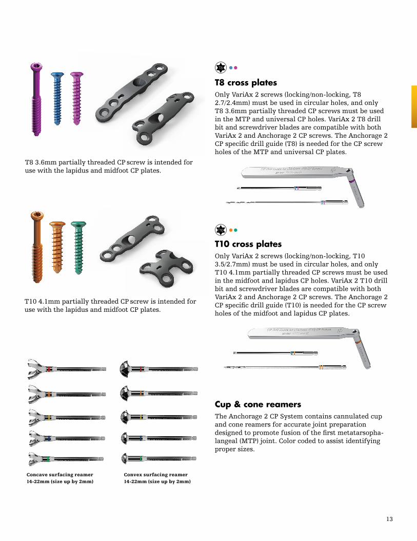
T8 cross platesOnly VariAx 2 screws (locking/non-locking, T8 2.7/2.4mm) must be used in circular holes, and only T8 3.6mm partially threaded CP screws must be used in the MTP and universal CP holes. VariAx 2 T8 drill bit and screwdriver blades are compatible with both VariAx 2 and Anchorage 2 CP screws. The Anchorage 2 CP specific drill guide (T8) is needed for the CP screw holes of the MTP and universal CP plates.
T10 cross platesOnly VariAx 2 screws (locking/non-locking, T10 3.5/2.7mm) must be used in circular holes, and only T10 4.1mm partially threaded CP screws must be used in the midfoot and lapidus CP holes. VariAx 2 T10 drill bit and screwdriver blades are compatible with both VariAx 2 and Anchorage 2 CP screws. The Anchorage 2 CP specific drill guide (T10) is needed for the CP screw holes of the midfoot and lapidus CP plates.
Concave surfacing reamer 14-22mm (size up by 2mm)
Convex surfacing reamer 14-22mm (size up by 2mm)
T8 3.6mm partially threaded CP screw is intended for use with the lapidus and midfoot CP plates.
T10 4.1mm partially threaded CP screw is intended for use with the lapidus and midfoot CP plates.
Cup & cone reamers The Anchorage 2 CP System contains cannulated cup and cone reamers for accurate joint preparation designed to promote fusion of the first metatarsopha-langeal (MTP) joint. Color coded to assist identifying proper sizes.
14
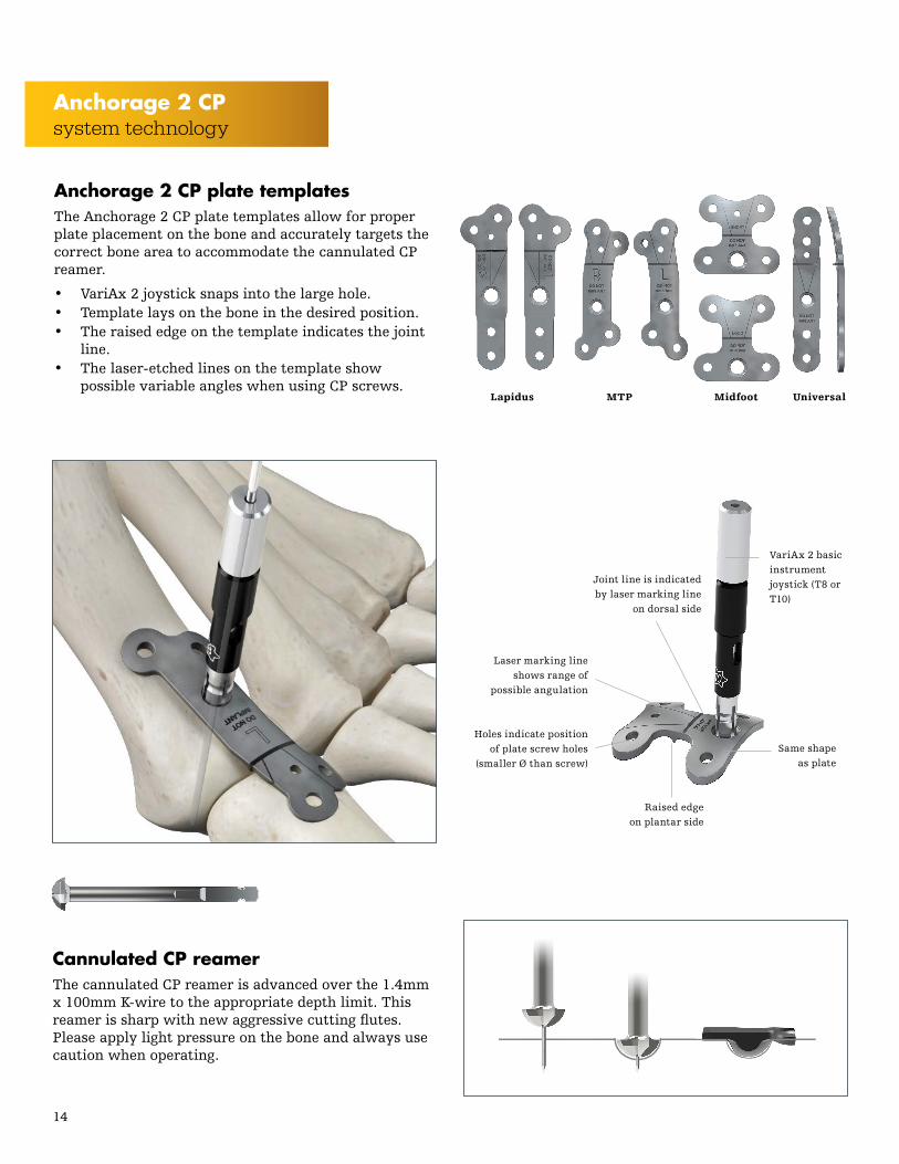
Same shape as plate
Laser marking line shows range of
possible angulation
Holes indicate position of plate screw holes
(smaller Ø than screw)
Joint line is indicated by laser marking line
on dorsal side
Raised edge on plantar side
Anchorage 2 CP plate templatesThe Anchorage 2 CP plate templates allow for proper plate placement on the bone and accurately targets the correct bone area to accommodate the cannulated CP reamer.
• VariAx 2 joystick snaps into the large hole.• Template lays on the bone in the desired position.• The raised edge on the template indicates the joint
line. • The laser-etched lines on the template show
possible variable angles when using CP screws.Lapidus MTP Midfoot Universal
Cannulated CP reamer The cannulated CP reamer is advanced over the 1.4mm x 100mm K-wire to the appropriate depth limit. This reamer is sharp with new aggressive cutting flutes. Please apply light pressure on the bone and always use caution when operating.
VariAx 2 basic instrument joystick (T8 or T10)
Anchorage 2 CPsystem technology

15
Introduction to cross plate (CP) technology
CP screwsThe Anchorage 2 CP System uses an inset diagonal, partially threaded screw to develop mechanical compression across the fusion site. This approach minimizes the need for separate, independent stabilization and is designed to create compression. The Anchorage 2 CP screws are self-tapping and self-drilling and feature an advanced new conical pitch thread and cutting flute that catches the far cortex faster and allows for maximum compression across the joint, resulting in successful unions.
Cross joint compression The Anchorage 2 CP system uses an inset diagonal, cross-joint screw to develop mechanical compression across the fusion site. This approach minimizes the need for separate, independent stabilization and is designed to create compression.
All Anchorage CP plates include:
• Oblique screw design, which offers an immediate stable construct
• Low profile design• Cannulated instrumentation, which helps promote
surgical efficiency
The CP plate concept was designed to allow maximum transmission of compression force across the joint, without the risk of the head of the screw fracturing the cortex and thus loosing stability. By creating a recess for the counterbore in the plate, it allows positioning of a compression screw through the plate. By first fixing the plate to the bone, the force of compression is borne by the plate and screw as the compression screw is set. This allows maximum compression and plate fixation to be accomplished in one step. This combination affords the compression of lag screw fixation combined with the stability of plate fixation.
The Anchorage 2 CP plates feature the patented VariAx SmartLock1 technology. The T10 and T8 locking screw heads are designed with threads on the underside, which upon insertion, engage the circular “lip” within any hole on the plate. The locking mechanism allows free angulation in all directions through a 30˚ cone.
Step 1 Step 2
Step 3
Step 4
Quick tipDo not apply VariAx 2 plate benders on Anchorage 2 CP plates. Bending of the plates will weaken the plate and compromise the CP technology.

16
CP screw angulation
Midfoot CP plate
Universal CP plate
MTP CP plate
Lapidus CP plate
Anchorage 2 CP platesNote: CP screws are to be used within a CP plate hole ONLY and not as an independent lag screw.
35° angle
50° angle
35° angle
35° angle
+/- 15° angle
25° angle
Variable angle Fixed angle
+/- 15° angle
+/- 7.5° angle
Anchorage 2 CPsystem technology

17
Option 1: flat cuts Perform a dorsal approach to expose the metatarsal head and the base of the proximal phalanx. Remove the articular surface of metatarsal head perpendicularly to the shaft. Hold the phalanx in position (15˚ valgus; 10-15˚ dorsiflexion). Make a parallel cut on proximal phalanx and proceed to the medial eminence Removal.
Place a guidewire into the middle of the base of the proximal phalanx and drive it out distal medial. Reduce the joint and then drive the pin back in a retrograde fashion into the metatarsal shaft for provisional fixation.
Option 2: cup and cone technique
Metatarsal preparation Displace the phalanx plantarly or laterally, according to the approach chosen to expose the metatarsal head. Using a powered drill, place a 1.4mm × 100mm K-wire (45-80200) proximally through the center of the meta-tarsal head and into the diaphysis. The largest diameter concave reamer (22mm) (XFR004222) is inserted over the K-wire. Reaming is performed until bleeding sub-chondral bone becomes visible on the joint surface. To ensure proper sizing, begin by using the largest size concave reamer, and then downsizing to match the diameter of the metatarsal head.
Note: Check the progress of the reamer frequently to prevent excessive shortening of the metatarsal. Take note of the last reamer size used.
Once metatarsal reaming is complete, the K-wire can be used to elevate the metatarsal head to enable the removal of bone on the plantar aspect.
Phalangeal preparation The proximal phalanx is plantarflexed using a Hohmann retractor (700664, 700665, 700667). A 1.4mm × 100mm K-wire is inserted into the center of the articular cartilage and directed through the diaphysis. Care should be taken not to penetrate the interphalan-geal joint. Reaming is initiated using the smallest size convex reamer (14mm) (XFR004214) inserted over the K-wire. Progressively increase the diameter of reamer used until the proximal phalanx is prepared with the same diameter utilized to prepare the metatarsal.
If the metatarsal reaming stopped at 18mm, the last and largest reamer used on the phalanx will be 18mm (XFR004218).
MTP joint preparation options

18
Incision/exposure A dorsal longitudinal incision is commonly used for MTP joint exposure. A medial approach may also be considered according to surgeon experience and patient indication. The incision is deepened and the EHL tendon retracted laterally. The joint capsule is released medial to the EHB tendon and retractors are placed to expose the base of the proximal phalanx and metatarsal head. An exostosectomy can be performed if necessary. A simulation of correction (metatarsus varus and pronation) is performed.
Preparation of metatarsophalangeal jointThe first MTP joint is prepared using flat cuts technique or the provided cup and cone reamers within the Anchorage 2 CP set (Refer to page 15 for detailed MTP exposure). Once prepared, the cup and cone surfaces can be aligned into desired position and temporarily stabilized using either a 1.4 × 100mm guidewire or a 1.6 × 200mm fully threaded wire.
StabilizationProper positioning can be evaluated by placing a support against the plantar surface of the foot. Once the desired position has been achieved, drive a K-wire 1.6mm × 200mm from the mid portion of the base of the proximal phalanx distally out the medial side. Then reduce the joint and drive it back in a retrograde fashion into the metatarsal for provisional fixation.
MTP CP preparationThe MTP CP template is oriented either R (705178) or L (705177). Loosen and insert the VariAx joystick for T8 screw holes (703927) into the large hole of the MTP template. After inserting the joystick tip in the circular hole, turn the knob on the upper part of the joystick clockwise to fix it. Proper template position is achieved when the raised edge on the MTP CP template is direct-ly over the metatarsophalangeal joint line. A 1.4mm × 100mm K-wire (45-80200) is inserted through the can-nulated VariAx joystick. Once the K-wire is positioned, the template and joystick are removed.
MTP CP - operative technique
Anchorage 2 CPoperative technique

19
MTP CP preparation (continued)The CP reamer (705172) is advanced over the same K-wire until the upper edge of the reamer is flush with the bone surface. The plate is positioned and temporarily fixated on the distal aspect of plate with a 1.4mm × 100mm K-wire . Once fixated, the proximal holes are drilled with T8 drill bits and filled with appropriate T8 screws.
Note: All circular holes accommodate both locking and non-locking T8 VariAx 2 screws (2.7mm and 2.4mm) with the exception of the CP hole.
Proximal screw insertionA 2.0mm drill bit (703896) for T8 VariAx 2 screws can be used in conjunction with the appropriate T8 drill guide to prepare the circular proximal holes for screw insertion. Insert distal screws on metatarsal after determining screw length with the VariAx 2/CP depth gauge (705170) to measure the appropriate length T8 screw to be inserted.
CP screwAfter proximal fixation is achieved, the T8 CP drill guide (705173) is positioned in the CP plate hole. A drill bit (703896) for T8 screws is used to drill to the plantar cortex of the proximal phalanx. Use the VariAx 2/CP depth gauge (705170) to measure the appropriate length T8 CP screw to be inserted. Once appropriate screw is measured, place through the CP hole. As CP screw seats in plate, all temporary fixation is removed. Final tightening of T8 CP screw develops compression across the joint with lag effect.
Distal screw insertionOnce compressed, the remaining distal screws can be inserted and verified with X-Ray.
Note: To avoid any risk of conflict with the cross joint screw, a maximum 12mm size screw is recommended. VariAx 2 screws can also be angulated to avoid the CP screw.
CP reamer 705172
K-wire 45-80200
VariAx 2 T8 drill guide
703684
Convex/concave surface reamers
Template for MTP cross-plate, left
705177
VariAx 2 joystick for T8 screw holes
703927
Drill bit, AO, Dia 2.0mm × 135mm,
scaled 703896
Drill guide for T8 cross-plates
705173
Instruments

20
Triple arthrodesis procedure The triple arthrodesis is a surgical procedure that relieves pain in the rear part of the foot by fusing the three main joints of the hindfoot: the subtalar joint, talonavicular joint, and the calcaneocuboid joint. This procedure improves the stability of the foot and in some cases corrects the deformity of the foot. After the foot is properly aligned and the fusion of subtalar joint is performed, fixation of the talonavicular joint is next.
Incision/exposure Incision for the talonavicular joint is made dorsomedially, beginning at the tip of the medial malleolus and in line with the medial border of the foot, extending 6-7cm toward the great toe longitudinally and ending between the anterior and posterior tibial tendons. Once exposed, all of the remaining cartilage from the joints is removed and prepared for fusion.
Preparation of talonavicular jointThe midfoot CP template comes in either short (705176) or long (705183) depending on the anatomy. The correct template size is chosen based on the length of the plate that spans the fusion site and leaves an adequate bony bridge between the plate screws. Loosen and insert the VariAx joystick for T10 screw holes (703928) into the appropriate midfoot CP template hole.
Midfoot TN - operative technique
Anchorage 2 CPoperative technique

21
Midfoot CP preparationAfter inserting the joystick tip in the circular hole, turn the knob on the upper part of the joystick clockwise to fix it. Proper position is achieved when the raised edge on the midfoot CP template is directly over the talona-vicular joint line. A 1.4mm × 100mm K-wire (45-80200) is inserted through the cannulated VariAx joystick. Once the K-wire is positioned, the template and joystick are removed. The CP reamer (705172) is advanced over the same K-wire until the upper edge of the reamer is flush with the bone surface.
Note: All circular holes accommodate both locking and non-locking T10 VariAx 2 screws (3.5mm and 2.7mm) with the exception of the CP hole.
Distal screw insertion A 2.6mm drill bit (703691) for T10 VariAx 2 screws can be used in conjunction with the appropriate T10 drill guide to prepare the hole for screw insertion. Insert distal screws on navicular after determining the screw length with the VariAx 2/CP depth gauge (705170) to measure the appropriate length T10 screw to be inserted.
CP screw The T10 CP drill guide (705173) is positioned inside the CP hole. Use the 2.6mm drill bit to accommodate the 4.1mm CP screw. Once drilled, use the VariAx 2/CP depth gauge to measure the appropriate length for the T10 CP screw to be inserted. When the appropriate screw length is measured, place the 4.1mm CP screw through the CP hole. As the CP screw is seated in the plate, all the temporary fixation is removed. Final tightening of the T10 CP screw develops compression across the joint with lag effect. Insert remaining proximal screws on the talus side of the joint and position under fluoroscopy.

22
Incision/exposure The incision can be extended distally for access to the cuneiforms, first metatarsal base and naviculocuneiform and intertarsal joints. Remove cartilage in the naviculo-cuneiform joint. If there is significant damage to tissue in the joints between the navicular and cuneiform, the remaining cartilage is removed. If the foot is misaligned, the bones need to be positioned correctly using a K-wire.
Midfoot CP preparationThe midfoot CP template comes in either short (705176) or long (705183) depending on the anatomy. The correct template size is chosen based on the length of plate that spans the fusion site and leaves an adequate bony bridge between the plate screws. Loosen and insert the VariAx joystick for T10 screw holes (703928) into the appropriate midfoot CP template hole. After inserting the joystick tip in the circular hole, turn the knob on the upper part of the joystick clockwise to fix it. Proper position is achieved when the raised edge on the midfoot CP template is di-rectly over the naviculocuneiform joint line. A 1.4mm x 100mm K-wire (45-80200) is inserted through the can-nulated VariAx joystick. Once the K-wire is positioned, the template and joystick are removed. The CP reamer (705172) is advanced over the same K-wire until the up-per edge of the reamer is flush with the bone surface.
Note: All circular holes accommodate both locking and non-locking T10 VariAx 2 screws (3.5mm and 2.7mm) with the exception of the CP hole.
Distal screw insertion A 2.6mm drill bit (703691) for T10 VariAx 2 screws can be used in conjunction with the appropriate T0 drill guide to prepare the hole for screw insertion. Insert dis-tal screws on cuneiform after determining screw length with the VariAx 2/CP depth gauge (705170) to measure the appropriate length T10 screw to be inserted.
CP screw The T10 CP drill guide (705173) is positioned inside the CP hole. Use the 2.6mm drill bit to accommodate the 4.1mm CP screw. Once drilled, use the VariAx 2/CP depth gauge to measure the appropriate length for the T10 CP screw to be inserted. When the appropri-ate screw length is measured, place 4.1mm CP screw through the CP hole. As the CP screw sits in the plate, all temporary fixation is removed. Final tightening of T10
Midfoot NC - operative techniqueCP screw develops compression across the joint with lag effect. Insert remaining proximal screws on the navicu-lar side of the joint and position under fluoroscopy.
Anchorage 2 CPoperative technique

23
Midfoot CC - operative technique
Quick tipDr. Keith Wapner
Extend CP screw across the length of the joint so to reach the plantar side of the bones. CP orienta-tion can be applied in either direction so that the CP screw can go from cuboid to calcaneus or from calcaneus to cuboid. In post traumatic cases, this will often be dictated by the shape of the bone.
Incision/exposure Expose the calcaneocuboid joint through a lateral (Ollier) incision. Distract the joint with a lamina spreader, and sharply debride the articular cartilage to expose the bleeding subchondral bone. Completely remove the cartilage from the calcaneocuboid joint.
Midfoot CP preparationThe midfoot CP template comes in either short (705176) or long (705183) depending on the anatomy. The correct template size is chosen based on the length of plate that spans the fusion site and leaves an adequate bony bridge between the plate screws. Loosen and insert the VariAx joystick for T10 screw holes (703928) into the appropriate midfoot CP template hole. After inserting the joystick tip in the circular hole, turn the knob on the upper part of the joystick clockwise to fix it. Proper position is achieved when the raised edge on the midfoot CP template is directly over the calcaneocuboid joint line. A 1.4mm x 100mm K-wire (45-80200) is inserted through the cannulated VariAx joystick. Once the K-wire is positioned, the template and joystick are removed. The CP reamer (705172) is advanced over the same K-wire until the upper edge of the reamer is flush with the bone surface.
Note: All circular holes accommodate both locking and non-locking T10 VariAx 2 screws (3.5mm and 2.7mm) with the exception of the CP hole.
Distal screw insertion A 2.6mm drill bit (703691) for T10 VariAx 2 screws can be used in conjunction with the appropriate T10 drill guide to prepare the hole for screw insertion. Insert distal screws on cuboid after determining screw length with the VariAx 2/CP depth gauge (705170) to measure the appropriate length T10 screw to be inserted.
CP screw The T10 CP drill guide (705173) is positioned inside the CP hole. Use the 2.6mm drill bit to accommodate the 4.1mm CP screw. Once drilled, use VariAx 2/CP depth gauge to measure the appropriate length for the T10 CP screw to be inserted. When appropriate screw length is measured, place the 4.1mm CP screw through the CP hole. As the CP screw sits in the plate, all temporary fixation is removed. Final tightening of the T10 CP screw develops compression across the joint with lag effect. Insert remaining proximal screws on calcaneus side of the joint and position under fluoroscopy.

24
Incision & preparation of tarsometatarsal joint An incision is made over the dorsal medial aspect of the first tarsometatarsal joint. Dissection is carried down through the subcutaneous tissues with care to identify and protect the anterior tibial tendon as it passes along the medial side of the medial cuneiform to insert on the plantar base of the first metatarsal. A dorsal capsulo-tomy is performed and the joint surfaces are debrided back to bleeding bone. After the joint preparation, re-duce the fragments and temporarily fixate using 1.6mm × 200mm K-wires.
Lapidus CP preparationThe lapidus CP template is oriented either R or L (705180, 705179). Loosen and insert the VariAx joystick for the T10 screw holes (703928) into the appropriate lapidus CP template hole. After inserting the joystick tip in the circular hole, turn the knob on the upper part of the joystick clockwise to fix it. Proper position is achieved when the raised edge on the lapidus CP template is directly over the tarsometatarsal joint line. A 1.4mm × 100mm K-wire (45-80200) is inserted through the cannulated VariAx joystick. Once the K-wire is positioned, the template and joystick are removed. The CP reamer (705172) is advanced over the same K-wire until the upper edge of the reamer is flush with the bone surface.
Note: All circular holes accommodate both locking and non-locking T10 VariAx 2 screws (3.5mm and 2.7mm) with the exception of the CP hole.
Distal screw insertionA 2.6mm drill bit (703691) for the T10 VariAx 2 screws can be used in conjunction with the appropriate T10 drill guide to prepare the hole for screw insertion. Insert distal screws into first metatarsal after deter-mining screw length with the VariAx 2/CP depth gauge (705170) to measure the appropriate length of T10 screw inserted.
Lapidus arthrodesis - operative technique
Anchorage 2 CPoperative technique

25
CP screwThe T10 CP drill guide (705171) is positioned inside the CP hole.
Note: The Anchorage 2 CP lapidus CP plate can be an-gulated in one direction only.
Use the 2.6mm drill bit to accommodate the 4.1mm CP screw. Once drilled, use the VariAx 2/CP depth gauge to measure the appropriate length for the T10 CP screw to be inserted. When the appropriate screw length is measured, place the 4.1 CP screw through the CP hole. As the CP screw sits in the plate, all temporary fixa-tion is removed. Final tightening of the T10 CP screw develops compression across the joint with lag effect. Insert remaining proximal screws and position under fluoroscopy.

26
Universal CP preparation Insert the VariAx joystick for the T8 screw holes (703927) into the universal CP template hole (705182). After inserting the joystick tip in the circular hole, turn the knob on the upper part of the joystick clockwise to fix it. Proper position is achieved when the raised edge on the universal CP template is directly over the joint line. A 1.4mm × 100mm K-wire (45-80200) is inserted through the cannulated VariAx joystick. Once the K-wire is positioned, the template and joystick are removed. The CP reamer (705172) is advanced over the same K-wire until the upper edge of the reamer is flush with the bone surface.
Note: All circular holes accommodate both locking and non-locking T8 VariAx 2 screws (2.7mm and 2.4mm) with the exception of the CP hole.
Distal screw insertionA 2.0mm drill bit (703896) for the T8 VariAx 2 screws can be used in conjunction with the appropriate T8 drill guide (703684) to prepare the hole for screw insertion. Insert the distal screws into metatarsal after determining the screw length with the VariAx 2/CP depth gauge (705170) to measure the appropriate length of the T8 screw inserted.
Universal CP - operative technique
Anchorage 2 CPoperative technique
27
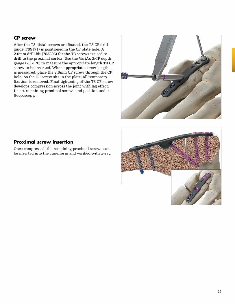
CP screwAfter the T8 distal screws are fixated, the T8 CP drill guide (705171) is positioned in the CP plate hole. A 2.0mm drill bit (703896) for the T8 screws is used to drill to the proximal cortex. Use the VariAx 2/CP depth gauge (705170) to measure the appropriate length T8 CP screw to be inserted. When appropriate screw length is measured, place the 3.6mm CP screw through the CP hole. As the CP screw sits in the plate, all temporary fixation is removed. Final tightening of the T8 CP screw develops compression across the joint with lag effect. Insert remaining proximal screws and position under fluoroscopy.
Proximal screw insertionOnce compressed, the remaining proximal screws can be inserted into the cuneiform and verified with x-ray.

This document is intended solely for the use of healthcare professionals. A surgeon must always rely on his or her own professional clinical judgment when deciding whether to use a particular product when treating a particular patient. Stryker does not dispense medical advice and recommends that surgeons be trained in the use of any particular product before using it in surgery.
The information presented is intended to demonstrate a Stryker product. A surgeon must always refer to the package insert, product label and/or instructions for use, including the instructions for Cleaning and Sterilization (if applicable), before using any Stryker product. Products may not be available in all markets because product availability is subject to the regulatory and/or medical practices in individual markets. Please contact your Stryker representative if you have questions about the availability of Stryker products in your area.
Stryker Corporation or its divisions or other corporate affiliated entities own, use or have applied for the following trademarks or service marks: Anchorage, SmartLock, Stryker, VariAx. All other trademarks are trademarks of their respective owners or holders.
The products listed above are CE marked.
AN-ST-2_Rev-2, 08-2016 Copyright © 2016 Stryker
Manufacturer:
Stryker GmbH Bohnackerweg 1 2545 Selzach, Switzerland
stryker.com
Foot & Ankle
References
1. Licensed from Prof. Wolter