variable speed drive xmv660
TRANSCRIPT

XMV660Variable Speed Drive
38-39
• Multi-level, pulse-width modulation with phase shift transformer• High efficiency and Power factor at partial loads• Low harmonics - IEEE 519 compliance• Low dV/dt - No motor derating or motor cable length restriction• Output voltage boosting • Redundancy - Automatic cell bypass• Rugged and maintenance friendly design

XMV660 MV drive goes one step further in achieving high performance by implementing proven low voltage technology within a modular and reliable configuration. An input phase shift transformer powers low voltage cells that are combined in series producing a quasi–sinusoidal current and voltage output wave with a reduced dV/dt and THDi level. It is designed under the strictest safety regulations and complies with the most demanding industrial requirements. The XMV660 is available in a wide voltage and power range, offering the best power quality, maximum motor care, uncompromising safety and reliability with reduced maintenance across the whole range.
MAXIMUM MOTOR CARE, OPERATOR SAFETY AND
RELIABILITY WITHOUT COMPROMISING MAINTENANCE
05.
XM
V6
60
SE
RIE
S

Discovering XMV660 Series
The XMV660 is based on a multi-step pulse width modulation (PWM). Low voltage power cells are connected in series producing a quasi-sinusoidal voltage and current motor wave. This topology offers a low dV/dt, THDi and HVF without output dV/dt or sinusoidal filters. This leads to reduce: peak voltages at the motor terminals, motor vibrations and overheating.
Power cells are connected to dedicated output terminals of the phase-shift transformer that can be configured from 18 to 54 pulse. This transformer offers a low THDi, high electric protection, and high power factor at low loads.
The control panel, which can be mounted over the transformer cabinet or in an adjoining cabinet, monitors the transformer status and communicates with power cells through fiber optics. At the same time, interacts with the user and DCS (Distributed Control system) through the colour touch-graphic display, serial communication ports, or I/O signals.
Input busbar Voltage & current measurement
Surge arresters
Cooling system
Main control & user terminal strip
40-41

Phase-shift input transformer
Outputbusbars Power Cells Phase U
Power Cells Phase VPower Cells Phase W
Pushbuttons & local control
power cellscabinet
05.
XM
V6
60
SE
RIE
S
control cabinet
transformercabinet
MEDIUM VOLTAGE / POWER ELECTRONICS

42-4242-43
Power qualityand efficiencyXMV660 topology meets the most stringent regulations regarding power quality (IEEE519) and electromagnetic compatibility (EMC 2004/108/EC).

MEDIUM VOLTAGE / POWER ELECTRONICS
• An input phase shift transformer from 18 to 54 pulses reduces the THDi level, thus no harmonics filters are needed.
• Outstanding Power Factor PF > 0.95 above 20% load, therefore no capacitor banks or active filters are needed.
• High efficiency ƞ > 96 % above 40% load ( Including transformer).
05.
XM
V6
60
SE
RIE
S
HIGHEST EFFICIENCY AND POWER FACTOR

44-45
Maximummotor care700V power cells combined in series generate a quasi sinusoidal voltage and current output waveform therefore achieving a low dV/dt, HVF and THDi. The XMV660 eliminates installation restrictions and additional expense that reduce profitably.

A low dV/dt reduces the voltage peaks at the motor winding and the common mode voltage (CMV) on the motor stator. Therefore, the XMV660 can be installed with new and existing motors with standard insulation and motor cables.
Negligible common mode currents (CMC) through motor bearings allow the use of standard bearings and lubrication.
Reduced motor losses caused by non sinusoidal waveforms (high THDi). There is no need to apply a power derating in medium voltage motors.
Reduced induced vibrations and torque pulses on the motor shaft by implementing a multi-step pulse width modulation (PWM) with low voltage power cells.
05.
XM
V6
60
SE
RIE
S
MEDIUM VOLTAGE / POWER ELECTRONICS
COMPATIBLE WITH NEW AND EXISTING MOTORS

46-47
Safety and protectionThe XMV660 integrates built-in hardware and software protections that reduce the associated risk of medium voltage facilities as standard.

An input phase-shift transformer offers a wide variety of benefits to your installation:
• Protects power rectifier bridge semiconductors and withstands grid transitory fluctuations.
• Reduces the short circuit power and therefore the fault current in case of an unlikely internal isolation defect.
• Compensates grid and drive voltage drops by using an on-site tap adjustment of the transformer. The motor will work under the rated voltage avoiding undesired motor oversizing and overheating.
• A tailor made input transformer allows the user to order a different input and output voltage. Thus, there is no need to install further transformers or switchgear, and allows the user to work with different rated voltage equipment within the same facilities.
The drive monitors the input, the output and each individual power cell offering multiple software and hardware protections that will take care of your costly rotating assets (pump, fan, conveyor, compressors…).
Each cell is protected by three fuses that provide overcurrent protection to the rectifier bridge.
The XMV660 can be delivered with a pre-charge system that magnetises the transformer and charges each cell DC bus. This system limits the inrush current at the drive’s connection.
The XMV660 can be delivered with input protection modules that avoid the need for medium voltage protection switchgear.
Safety system, mechanical interlocks, restricted settings access with password and a warning buzzer will warn you of undesirable settings.
05.
XM
V6
60
SE
RIE
S
MAXIMUMOPERATOR SAFETY
MEDIUM VOLTAGE / POWER ELECTRONICS

48-49
Maximum reliabilityand availabilityA multi-step topology based on proven low voltage semiconductors ensures service life, quality and availability.

05.
XM
V6
60
SE
RIE
S
The XMV660 is delivered fully factory tested to ensure the best performance under any load condition.
Transformer’s and cell’s temperature are permanently monitored to detect fan clogging or failure. Additionally the drive is available with a redundant cooling system that maximises the availability rate.
The XMV660 is delivered with a bypass in each cell and a centralised algorithm that permits the drive to keep running even when one or more cells fail, and at maximized output voltage.
The XMV660 is available with different cell topologies that improve built-in standard features (regenerative, reduced size…), for further information consult Power Electronics.
CELL TYPOLOGIES
MEDIUM VOLTAGE / POWER ELECTRONICS

Maintenancefriendly
50-51
The XMV660 is delivered with three adjoining, integrated or separate cabinets: power transformer cabinet, power cells cabinet and control cabinet.

MEDIUM VOLTAGE / POWER ELECTRONICS
All of the cabinets are designed to provide an easy front access that simplifies maintenance and supervision. The transformer cabinet can be installed out of the plant room in order to reduce indoor heat loads.
Low voltage test allow a safely fully functional performance before commissioning.
An accessible front connection together with a guide frame permits power cells to be manually changed by an operator with the aid of a trolley.
A redundant design of the power conversion stage and cooling system increases availability rates with a reduced stock of spare parts.
Filters and gratings are easily removable from the front without opening the cabinet or disturbing the normal operation of the application. Hence providing maximum safety to routine maintenance tasks.
05.
XM
V6
60
SE
RIE
S
AN EASY FRONT ACCESS SIMPLIFIES
MAINTENANCE AND SUPERVISION

Accurate, powerfuland flexible motor control
52-53
Power Electronics’ success is measured by our customer’s satisfaction so the motor control systems developed by Power Electronics have been designed to meet the most demanding features. It integrates the V/f control and two vector controls: the Power Motor Control (PMC) and the Advanced Vector Control (AVC) as standard.

05.
XM
V6
60
SE
RIE
SQuick and powerful responsePMC and AVC allow its application in high starting torque, dynamic or precise applications. The XMV660 is suitable for all existing applications.
No auto tuning needPMC factory settings and motor nameplate parameters ensure perfect performance without enabling the auto tuning function during commissioning. We have invested in new control methods to simplify settings. A fast and reliable commissioning saves time and money.
Start and Stop maximum controlThanks to the MBC (Mechanical Brake Control), the Pre-Magnetisation and Delay off IGBT, the loaded process will have a smooth start and stop.
Multiple drive’s synchronizationPMC-OLTC is the unique master-slave motor control that allows the synchronisation of multiple drives and motors without encoder. The result is a smooth, powerful and fast response with the least maintenance and supervision. Every motor will provide the same torque under any circumstance, therefore ageing all the motors homogeneously. Moreover, its reduced starting in-rush current peaks allow the reduction of the drive and motor oversizing in demanding conveyors and mills.
Non-stop Power Cell BypassWhen one or more power cells fail, the drive depending on the fault severity, automatically cuts off the power to the motor and bypasses the damaged cells. Then without loosing the motor synchronisation, recalculates phase to phase angles to maximise output voltage (neutral-shift algorithm) and re-connects in a few milliseconds.
Additional functionalitiesThermal motor protection, motor overload prediction, motor stall, fly start, automatic restart, etc... complete the wide control features.
MEDIUM VOLTAGE / POWER ELECTRONICS

54-5454-55
Easy to driveIn Power Electronics, we have developed the XMV660 with an user-friendly interface and fully compatible with the most extended industrial protocols, which leads into a comfortable workflow. Intuitive and comprenhensive screens and buttons enhance user’s control and configuration.
MEDIUM VOLTAGE / POWER ELECTRONICS
05.
XM
V6
60
SE
RIE
S
• 3,5 " Touch Screen (240x320 pixels) with pen
• Built-in Help System
• Save and Copy the parameter configuration
for fast commissioning
• Quad Band GSM modem integrated to remote
start, stop and notification by SMS option
• Optional 5Vdc external power supply
or batteries
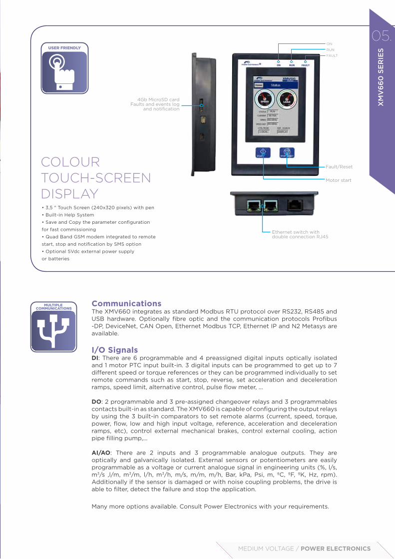
CommunicationsThe XMV660 integrates as standard Modbus RTU protocol over RS232, RS485 and USB hardware. Optionally fibre optic and the communication protocols Profibus -DP, DeviceNet, CAN Open, Ethernet Modbus TCP, Ethernet IP and N2 Metasys are available.
I/O Signals DI: There are 6 programmable and 4 preassigned digital inputs optically isolated and 1 motor PTC input built-in. 3 digital inputs can be programmed to get up to 7 different speed or torque references or they can be programmed individually to set remote commands such as start, stop, reverse, set acceleration and deceleration ramps, speed limit, alternative control, pulse flow meter, ...
DO: 2 programmable and 3 pre-assigned changeover relays and 3 programmables contacts built-in as standard. The XMV660 is capable of configuring the output relays by using the 3 built-in comparators to set remote alarms (current, speed, torque, power, flow, low and high input voltage, reference, acceleration and deceleration ramps, etc), control external mechanical brakes, control external cooling, action pipe filling pump,...
AI/AO: There are 2 inputs and 3 programmable analogue outputs. They are optically and galvanically isolated. External sensors or potentiometers are easily programmable as a voltage or current analogue signal in engineering units (%, l/s, m3/s ,l/m, m3/m, l/h, m3/h, m/s, m/m, m/h, Bar, kPa, Psi, m, ºC, ºF, ºK, Hz, rpm). Additionally if the sensor is damaged or with noise coupling problems, the drive is able to filter, detect the failure and stop the application.
Many more options available. Consult Power Electronics with your requirements.
COLOUR TOUCH-SCREEN DISPLAY
4Gb MicroSD cardFaults and events log
and notification
Ethernet switch withdouble connection RJ45
FAULT
RUN
ON
Fault/Reset
Motor start

Dedicated software tools and Macros
56-57
Real performance information about motor and drive status. The XMV660 integrates an accurate power grid analyser and drive diagnosis function.

MEDIUM VOLTAGE / POWER ELECTRONICS
05.
XM
V6
60
SE
RIE
S
PowerCOMMSThe PowerCOMMS tool offers real performance information about motor and drive status. The XMV660 integrates an accurate power grid analyser and drive’s diagnosis function. This tool executed from a PC, and communicated with the drives through Ethernet or RS485/RS232, registers, plots and exports all the drive visualisation parameters: energy consumption, regenerated energy, motor voltage, PTC signal, IGBT temperature, motor overload, Power Cells status, etc.
Not only can you monitor both drive and motor, you can also remotely control and commission multiple drives. User-friendly and flexible tool to copy and save the XMV660 parameters remotely to speed up the commissioning or configuration, saving time and money.
PowerPLCPowerPLC tool will enhance the XMV660 performance implementing multiple functions without additional hardware. Dedicated software for customers’ application.
Multiple motor control, automatic pump and crusher unclogging, compressor regulation, cranes driving, petrol pump softstart, paper and cable rolling control, biogas digesters mixers, accumulators, calendar functions, and much more... The user establishes the limits for the XMV660.
WE HAVE INVESTED IN NEW SOFTARE TOOLS TO SIMPLIFY
SETTINGS AND OPERATION

58-59
Technical Characteristics
INPUT
Input voltage (kV) [1] 2.3kV to 11kV (±10%), (Voltage/Power Ride Through -35%)
Frequency 50/60Hz (±10%)
Power factor > 0.95 (over 20% load)
THDi (%) current < 5% [2]
Power transformer Phase-shift transformer, dry type (From 18 to 54)
Overvoltage protection Surge Arresters
Drive bypass Optional bypass cabinet
OUTPUT
Technology Multi-level, pulse-width modulation, low voltage power cells connected in series.
Output voltage (kV) 2.3kV, 3kV, 3.3kV, 4.16kV, 5kV, 5.5kV, 6kV, 6.6kV, 10kV, 11kV
Pulses / power cells in series 18p/3, 24p/4, 30p/5, 36p/6, 54p/9
Power cells (A) / (V) 100A, 200A, 300A, 400A, 600A / 600V-700V
Overload capacity 150% (60s/10min)
Current harmonic distortion (THDi) < 5%
dV/dt value < 1000V/µs (Multi-level topology reduce peak voltages)
Harmonic voltage factor (HVF) < 0.019 ( No motor derating required)
Frequency 0.5 to 120Hz. (0.01Hz accuracy)
Efficiency ≥96% (including transformer)
Power cell bypass Built-in as standard
Output voltage balance Neutral phase shift
Output voltage boosting Space vector modulation
ENVIRONMENTALRATINGS
Operation conditions Indoor, No caustic and volatile air, no dust
Degree of protection IP41 (IEC60529) / IP54 Optional
Operation temperature 0ºC to +50ºC; >50ºC power derating 1%/ºC Pn
Storage temperature -25ºC a +55ºC
Humidity < 90%, non condensing
Altitude <1000m; >1000m power derating 1%/100m. Máx. 3000m
Cooling Forced air cooling. Optional redundant
CONTROL
Control modeLocal control (Colour touch-screen display 3.5” and push-button)Remote control I/O
Control method
V/hz
VECTOR CONTROLOpen Loop: PWM speed / torque control, AVC: speed / torque controlClose Loop (Encoder): PWM speed / torque control, AVC: speed / torque control
Carrier frequency 1kHz
Control power supply Redundant 2x230Vac II P+N (3kVA), UPS integrated
Other characteristicsVoltage/Power ride through, quick setting and commisioning, master-slave synchronization, skip critical frequencies, delay-off IGBt, motor pre-magnetization, flux reduction at low load (energy saver), electric DC brake, multi-reference and speed ramp, Power PLC programming, Other consult Power Electronics.
LOCAL CONTROL PANEL
Display Color touch-screen display TFT 3.5”
Connection RJ45, 3m (5m Optional)
Features
4Gb MicroSD card | Faults and events log and notification, save and copy the parameters. Quad Band GSM modem integrated to remote start, stop and notification by SMS.Ethernet switch with double connection RJ45Self powered by RJ45, optional 5Vdc external power supply or batteriesComprenhensive screens with built-in help systemCoded access to parameters with pasword
Leds Led on: Control board is energizedLed run: Motor receiving power supplyLed fault: Flashing displays that a fault has occurred
Display information
Average current and 3-phase motor current, Average voltage and 3-phase motor voltage, Average input voltage and 3-phase input voltage, 3-phase input and output frequency, Drive Status, Speed, Torque, Power, Power factor of motor, Individual Cells status, Register of total and partial drive running time with reset function. (hours), Register of total and partial drive energy consumption with reset function (kWh), Relay status, Digital inputs / PTC status, Output comparator status, Analogue inputs and sensor values, Analogue output value, Motor overload and equipment status, Drive and rectifier temperature, Fault history (last 6 faults).
Visualization leds Red: Running, Green: Stopped, Amber:Warning, Red: Fault
Push buttons
Control mode selector: local/stop/remoteEmergency StopGreen: Local start push buttonRed: Local Stop push buttonWhite: Fault Reset

USERINTERCONNECTION [1]
Digital inputs
5 programmable, Active high (24Vdc), Isolated power supply
5 pre-configurated (Start/Stop ; Reset, control mode, reference)
1 PTC input
Analogue inputs 3 programmable differential inputs. 0 – 20mA, 4 – 20mA, 0 – 10Vdc and ±10Vdc. (Optically isolated)
Digital outputs
2 programmable changeover relays (250Vac, 8A or 30Vdc, 8A)
3 programmables NO contacts (250Vac, 8A or 30Vdc, 8A)
3 pre-configured contacts (Start/Stop, Warning, Failure)
Analogue outputs3 isolated programmable outputs:
0 – 20mA, 4 – 20mA, 0 – 10Vdc and ±10Vdc
Encoder (optional) 2 differential encoders input (process y vector control).Input signal from 5 to 24Vdc
COMMUNICATIONS
Standard hardware USB, RS232, RS485
Optional hardware Fiber optics, Ethernet, 9 Pin D-SUB, CAN
Standard protocol Modbus-RTU
Optional protocolProfibus-DP, DeviceNet, Ethernet (Modbus TCP),
Ethernet IP, CAN Open, N2 Metasys
PROTECTIONS
Motor protections
Rotor locked, torque limit, Motor overload (thermal model), Output current limit, Phase current imbalance, Ground fault current, Phase voltage imbalance, Motor over-temperature (PTC signal), Speed limit, excessive starting and stopping time.
Drive protections
Input phase loss, Low input voltage, High input voltage, maximum number of faulty cells, High input frequency, Low input frequency, drive overload, drive over-temperature, Analogue input signal loss (speed reference loss), communication loss (time-out), Power supply fault, Emergency stop
Power cells protections
Overcurrent (fuses), high DC bus voltage, Low DC bus voltage, DC bus voltage instability, low input voltage, fiber optics communication lost, communication time overpassed (time-out), control voltage lost, gate drive fault, power cell overtemperature.
REGULATION
Electromagnetic compatibilityDirectiva EMC 2004/108/EC
IEC/EN 61800-3
IEEE 519-1992
VSD design and construction
IEC/EN 61800-4 General requirements
IEC/EN 61800-5-1 Safety
IEC/EN 60146-1-1 Semiconductor converters
MV transformer
IEC/EN 60076 -1, -11
IEC/EN 60146-1-3
IEC/EN 61378-1
05.
XM
V6
60
SE
RIE
S
NOTES [1] Other configurations, consult Power Electronics. [2] Harmonics are below the limits defined in IEEE519 for all ISC/IL.
MEDIUM VOLTAGE / POWER ELECTRONICS

Customised solutions
60-61
Experienced engineers in medium voltage facilities and backed by our R&D and Production departments, are willing to modify standard unit to comply with your specific requirements and support you during the plant lay-out. Factory tested solutions that provide flexibility and reliability.

MEDIUM VOLTAGE / POWER ELECTRONICS
Control, user terminal stripand pushbuttons:• Pushbottons, selectors and pilots.• Digital and analogue I/O pre-configuration • Customised user terminal strip • PTC and PT100 relays • Process and motor encoder boards.• Optional communication protocols (Profibus-DP, Dvicenet, Ethernet Modbus TCP, N2 Metasys, CAN Open…) • Power PLC dedicated applications
Bypass andinput protection cells:• VSD bypass with fully controlled line and bypass vacuum contactors• Automatic circuit breaker, fuses, withdraw-able contactor, on-load disconnector with or without fuses. • Earthing switch• ATEX relay and output disconnection cell• Motor protection relay• Commutation cells• Soft-load system
Cabinet features:• IP54 protection degree, stainless steel enclosure, specific RAL, tailor made labelling. • Incoming MV cable or busbar connection from top, right or backside.• Lined up VSD with common main input busbar and protection.
05.
XM
V6
60
SE
RIE
S
Documentation:• Electrical and dimensional drawings.• ITP reports• Witness factory Aceptance test (FAT)• ….

62-63
XMV66 100 030 X Y Z - - -
XMV660Series
Rated Output Current [1] Rated Voltage Overload % Degree of
Protection Model [2] Cable access Soft Load System Cooling Redundancy Nominal Input Voltage[2]
100 100A 023 2.3kV(9 cells) 1 110%
Light Duty 4 IP41 A Asynchronous motor - Bottom input and output - Not included - Not included -
Nominal Output Voltage
200 200A 030 3kV(9 cells) 2 120%
Normal Duty 5 IP54[2] S Synchronous motor T Top input and bottom output C Included V Included A 2.3kV
300 300A 033 3.3kV(9 cells) 5 150%
Heavy Duty R Asynchronous motor4Q Regenerative U Top input and
output B 3kV
400 400A 416 4.16kV (12 cells) ... Under
request W[1] Synchronous motor 4Q C 3.3kV
600 600A 060 6kV (18 cells) M
Asynchronous motor4Q Regenerative
Monophase Bridge rectifier
D 4.16kV
... Underrequest 066 6.6kV
(18 cells) E 6kV
100[2] 10kV (27 cells) F 6.6kV
110[2] 11kV (27 cells) G 7.2kV
H 10kV
I 11kV
J 12kV
... Underrequest
CONFIGURATION TABLE - XMV660
DIMENSIONS - XMV660
Configuration tableDimensions
NOTES [1] Check the rated current of the motor nameplate and indicate the short circuit current to guarantee the compatibility with the selected drive. [2] Consult availability with Power Electronics [3] Preliminary, consult Power Electronics the definitive values. Request your quote by filling the ordering info template; please consult Power Electronics with your additional demands
Rated current WidthW (mm)[3]
Depth D (mm)
HeightH (mm)*
Heighth (mm)
2.3kV-3.3kV
< 100A 2515 1200 2650 2320
101A – 200A 3000 1200 2650 2320
201A – 300A 3500 1400 2650 2320
301A – 400A 4400 1400 2650 2320
> 400A Under request
4.16kV
< 100A 2700 1200 2650 2320
101A – 200A 3430 1400 2650 2320
201A – 300A 4400 1400 2650 2320
301A – 400A 5000 1400 2650 2320
> 400A Under request
6kV- 6.6kV
< 100A 3430 1400 2650 2320
101A – 200A 4600 1400 2650 2320
201A – 300A 5300 1400 2650 2320
301A – 400A 6600 1400 2650 2320
> 400A Under request

MEDIUM VOLTAGE / POWER ELECTRONICS
XMV66AR 0100 6 4 SE - - -
Módulo ProtecciónXMV660
Rated output current Rated voltage Degree of
Protection Configuration Power cable access Fuse Protection Earthing Switch
0100 100A 2 2300V 4 IP41 IA Automatic Circuit Breaker - Bottom input and
output - Not included - Not included
... ... 3 3000V-3300V 5 IP54[2] SF Disconnector with fuses T Top input and
bottom output F Included E Included
2000 2000A 4 4160V CX Withdrawable Line contactor U Top input and
output
... Under request 6 6000V-6600V SE Disconnector and
earthing switch
8 10000V-11000V[2] BP Line contactor and bypass contactor
- Under request
DIMENSIONS - PROTECTION MODULE XMV660
CONFIGURATION TABLE - PROTECTION MODULE XMV660
CONFIGURATION
DIMENSIONS
WIDTHW (mm)
DEPTHD (mm)
HEIGHTH (mm)
IA / SF / SE /BP 900 1200 / 1400 2320
NOTES [1] Check the rated current of the motor nameplate and indicate the short circuit current to guarantee the compatibility with the selected drive. [2] Consult availability with Power Electronics
Please consult Power Electronics with your demands.
05.
XM
V6
60
SE
RIE
S

64-63
Standard ratings
STANDARD RATINGS - XMV660
XMV660 2.3kV
CODENOMINAL
CURRENT (A)MOTOR POWER
(kW) (HP)[1]
XMV66050 023 50 149 200
XMV66060 023 60 186 250
XMV66070 023 70 224 300
XMV66080 024 80 261 350
XMV66090 023 90 298 400
XMV66100 023 100 336 450
XMV66120 023 120 373 500
XMV66140 023 140 447 600
XMV66170 023 170 522 700
XMV66190 023 190 597 800
XMV66210 023 210 671 900
XMV66230 023 230 746 1000
XMV66300 023 300 932 1250
XMV66350 023 350 1119 1500
XMV66410 023 410 1305 1750
XMV66470 023 470 1491 2000
XMV66530 023 530 1678 2250
XMV66590 023 590 1864 2500
XMV660 3kV
CODENOMINAL
CURRENT (A)MOTOR POWER
(kW)[2] (HP)
XMV66050 030 50 200 268
XMV66060 030 60 250 335
XMV66075 030 75 315 422
XMV66085 030 85 355 476
XMV66100 030 100 400 536
XMV66110 030 110 450 603
XMV66120 030 120 500 671
XMV66135 030 135 560 751
XMV66150 030 150 630 845
XMV66170 030 170 710 952
XMV66200 030 200 800 1073
XMV66220 030 220 900 1207
XMV66240 030 240 1000 1341
XMV66300 030 300 1250 1676
XMV66340 030 340 1400 1877
XMV66390 030 390 1600 2146
XMV66430 030 430 1800 2414
XMV66480 030 480 2000 2682
XMV66540 030 540 2240 3004
XMV66600 030 600 2500 3353[1] HP standard motor rated power (cos φ • Eff = 0.8, 2.3kV)
[2] kW standard motor rated power (cos φ • Eff = 0.8, 3kV)
64-65

NOTE Request your quote by filling the Ordering info template; please consult Power Electronics with your additional demands. Variable speeds drives over 400A and 7.2kV will be engineered under request, consult availability.
STANDARD RATINGS - XMV660
XMV660 3.3kV
CODENOMINAL
CURRENT (A)MOTOR POWER
(kW) [3] (HP)
XMV66045 033 45 200 268
XMV66055 033 55 250 335
XMV66070 033 70 315 422
XMV66080 033 80 355 476
XMV66090 033 90 400 536
XMV66100 033 100 450 603
XMV66110 033 110 500 671
XMV66120 033 120 560 751
XMV66140 033 140 630 845
XMV66150 033 150 710 952
XMV66175 033 175 800 1073
XMV66200 033 200 900 1207
XMV66220 033 220 1000 1341
XMV66270 033 270 1250 1676
XMV66310 033 310 1400 1877
XMV66350 033 350 1600 2146
XMV66400 033 400 1800 2414
XMV66440 033 440 2000 2682
XMV66490 033 490 2240 3004
XMV66550 033 550 2500 3353
[3] kW standard motor rated power (cos φ • Eff = 0.8, 3.3kV)
XMV660 4.16kV
CODENOMINAL
CURRENT (A)MOTOR POWER
(kW) (HP) [4]
XMV66050 416 50 298 400
XMV66060 416 60 336 450
XMV66070 416 70 373 500
XMV66080 416 80 447 600
XMV66090 416 90 522 700
XMV66100 416 100 597 800
XMV66120 416 120 671 900
XMV66130 416 130 746 1000
XMV66160 416 160 932 1250
XMV66200 416 200 1119 1500
XMV66230 416 230 1305 1750
XMV66260 416 260 1491 2000
XMV66290 416 290 1678 2250
XMV66320 416 320 1864 2500
XMV66360 416 360 2051 2750
XMV66390 416 390 2237 3000
XMV66450 416 450 2610 3500
XMV66520 416 520 2983 4000
XMV66580 416 580 3356 4500
[4] HP standard motor rated power (cos φ • Eff = 0.8, 4.16kV)
MEDIUM VOLTAGE / POWER ELECTRONICS
05.
XM
V6
60
SE
RIE
S

66-67
Standard ratings
STANDARD RATINGS - XMV660
XMV660 6kV
CODENOMINAL
CURRENT (A)MOTOR POWER
(kW) [5] (HP)
XMV66050 060 50 400 536
XMV66055 060 55 450 603
XMV66060 060 60 500 671
XMV66070 060 70 560 751
XMV66080 060 80 630 845
XMV66085 060 85 710 952
XMV66100 060 100 800 1073
XMV66110 060 110 900 1207
XMV66120 060 120 1000 1341
XMV66150 060 150 1250 1676
XMV66170 060 170 1400 1877
XMV66190 060 190 1600 2146
XMV66220 060 220 1800 2414
XMV66240 060 240 2000 2682
XMV66270 060 270 2240 3004
XMV66300 060 300 2500 3353
XMV66340 060 340 2800 3755
XMV66380 060 380 3150 4224
XMV66430 060 430 3550 4761
XMV66480 060 480 4000 5364
XMV66540 060 540 4500 6035
XMV66600 060 600 5000 6705
XMV660 6.6kV
CODENOMINAL
CURRENT (A)MOTOR POWER
(kW) [6] (HP)
XMV66045 066 45 400 536
XMV66050 066 50 450 603
XMV66055 066 55 500 671
XMV66060 066 60 560 751
XMV66070 066 70 630 845
XMV66080 066 80 710 952
XMV66090 066 90 800 1073
XMV66100 066 100 900 1207
XMV66110 066 110 1000 1341
XMV66140 066 140 1250 1676
XMV66150 066 150 1400 1877
XMV66180 066 180 1600 2146
XMV66200 066 200 1800 2414
XMV66220 066 220 2000 2682
XMV66250 066 250 2240 3004
XMV66270 066 270 2500 3353
XMV66300 066 300 2800 3755
XMV66350 066 350 3150 4224
XMV66390 066 390 3550 4761
XMV66440 066 440 4000 5364
XMV66500 066 500 4500 6035
XMV66550 066 550 5000 6705
[5] kW standard motor rated power (cos φ • Eff = 0.8, 6kV) [6] kW standard motor rated power (cos φ • Eff = 0.8, 6.6kV)

MEDIUM VOLTAGE / POWER ELECTRONICS
STANDARD RATINGS - XMV660
XMV660 10kV
CODENOMINAL
CURRENT (A)MOTOR POWER
(kW)[7] (HP)
XMV66020 100 20 315 422
XMV66025 100 25 355 476
XMV66030 100 30 400 536
XMV66035 100 35 500 671
XMV66040 100 40 560 751
XMV66045 100 45 630 845
XMV66050 100 50 710 952
XMV66060 100 60 800 1073
XMV66065 100 65 900 1207
XMV66070 100 70 1000 1341
XMV66090 100 90 1250 1676
XMV66100 100 100 1400 1877
XMV66115 100 115 1600 2146
XMV66130 100 130 1800 2414
XMV66145 100 145 2000 2682
XMV66160 100 160 2240 3004
XMV66180 100 180 2500 3353
XMV66200 100 200 2800 3755
XMV66230 100 230 3150 4224
XMV66260 100 260 3550 4761
XMV66290 100 290 4000 5364
XMV66325 100 325 4500 6035
XMV66360 100 360 5000 6705
XMV66400 100 400 5600 7510
XMV660 11kV
CODENOMINAL
CURRENT (A)MOTOR POWER
(kW)[8] (HP)
XMV66020 110 20 315 422
XMV66023 110 23 355 476
XMV66025 110 25 400 536
XMV66030 110 30 500 671
XMV66035 110 35 560 751
XMV66040 110 40 630 845
XMV66045 110 45 710 952
XMV66050 110 50 800 1073
XMV66060 110 60 900 1207
XMV66065 110 65 1000 1341
XMV66080 110 80 1250 1676
XMV66090 110 90 1400 1877
XMV66100 110 100 1600 2146
XMV66120 110 120 1800 2414
XMV66130 110 130 2000 2682
XMV66150 110 150 2240 3004
XMV66165 110 165 2500 3353
XMV66185 110 185 2800 3755
XMV66210 110 210 3150 4224
XMV66230 110 230 3550 4761
XMV66260 110 260 4000 5364
XMV66300 110 300 4500 6035
XMV66330 110 330 5000 6705
XMV66370 110 370 5600 7510
[7] kW standard motor rated power (cos φ • Eff = 0.8, 10kV) [8] kW standard motor rated power (cos φ • Eff = 0.8, 11kV)
NOTE Request your quote by filling the Ordering info template; please consult Power Electronics with your additional demands. Variable speeds drives over 400A and 7.2kV will be engineered under request, consult availability.
05.
XM
V6
60
SE
RIE
S

68-69
Warranty POWER ELECTRONICS guarantees supply against any anomaly which can be directly and exclusively attributed to design, fabrication, manufacture or material defect, thus in case those faults or defects are identified before the end of warranty, POWER ELECTRONICS undertakes to repair them in a maximum time span of 24/48h. POWER ELECTRONICS provides its clients with a 24h/365 days a year technical service. Lacking a specific agreement in particular terms, the period of the warranty is of THREE years. In application of that warranty, POWER ELECTRONICS commits to repair or replace the faulty parts. The client must communicate to POWER ELECTRONICS immediately any obvious defect, describing its nature in detail and allowing POWER ELECTRONICS to control and correct this fault. The possible expenses caused by transport, customs, expenses, etc and those related to dismounting and assembling the corrected or substituted part, will be covered by POWER ELECTRONICS, except in those cases in which the client whishes to carry out those tasks with the previous approval by POWER ELECTROINCS, which no cost for the manufacturer.
The warranty will only be valid when the transport, storage, assembly, installation, commissioning, functioning and maintenance in the delivery have all been carried out correctly by authorized personnel and in accordance with the enclosed instructions manual. The warranty exclusively includes the repair of defects and/or exchange of faulty parts on our own products. The warranty will be void in normal cases of wear and tear, being ordinary caused by functioning or external causes, or extraordinary caused by an overcharge of work load, wrong use or external causes as can be excessive humidity, dust, corroding products, electromagnetic fields, static energy, fluctuations in the quality of the electrical supply, etc. And, does not cover defects caused by accidents, by transport, inadequate storage or conservation, and in general faults which are not attributable or are out of POWER ELECTRONICS’ control.
The client does not have authorization to personally repair, or do so through a third party, nor can he send the equipment to be corrected or replaced, without the specific authorization by POWER ELECTRONICS. The warranty will be void if the client or any third parties make any intervention, modification, or repair without the previous written consent by POWER ELECTRONICS, or if they do not fulfill the immediate requirements to avoid an aggravation of the damage. The warranty will not cover in any case the damage, whether direct or not, to people or objects, and in no case will the faulty equipment include compensation or payment for lack of productivity by the client or by the final user, and this is the only warranty given to the client, substituting any previous mentioned conditions or warranty, both implicit and legal, which have not been expressly accepted by POWER ELECTRONICS. The warranty always frees POWER ELECTRONICS from having to answer to faults which occur after the mentioned period. The repair or replacement of a faulty equipment at arrival will not modify the initial date of the warranty period for the global equipment. The substituted equipment will be property of POWER ELECTRONICS.

MEDIUM VOLTAGE / POWER ELECTRONICS
Contact05.
WA
RR
AN
TY
/ C
ON
TAC
T

WHEN YOU HAVE A GREAT TEAM, ANYTHING IS POSSIBLE
70-5570-71
ALEIX AND RANDYHAVE RACED MORETHAN 4000KM WITH POWER ELECTRONICS

05.
SPO
NSO
RSH
IP
MEDIUM VOLTAGE / POWER ELECTRONICS
Over time, Power Electronics has actively supported sports which share the values of personal overcome, dedication and team work. Values that represent the cornerstone of all the areas of work, life and sport.
Since 2012, Power Electronics has become the main sponsor of one of the leading motorbikes teams of the moto GP world championship. Commanded by Jorge Martinez “Aspar”, the POWER ELECTRONICS ASPAR TEAM has already won its first CRT championship. We count on two pilots that combine both experience and youth, the Spanish Aleix Espargaró and the French Randy de Puniet, aggressive and competitive riders that struggle to get the top.
The high number of followers and its position in those countries where Power Electronics is carrying out a internationalization strategy, make the moto GP world championship a perfect launching pad to make Power Electronics a well known worldwide brand. Furthermore, we are a company dedicated to the manufacturing of cutting-edge technology and are proud of helping and supporting companies who invest their resources in innovation. Same as we do.
Power Electronics Aspar Team is a step further in our sponsorship strategy of supporting sports. It began for some time now in a local level and still continues by supporting grassroots sport (San Jose School) and Valencia Basket, team which nowadays is already linked to us.

GC
A0
3AI
PO
WE
R E
LEC
TR
ON
ICS
res
erve
s th
e ri
ght
to
mo
dif
y w
hole
or
par
t o
f th
e co
nten
t o
f th
is b
roch
ure
at a
ny t
ime
and
wit
hout
pri
or
noti
ce. J
une
2013

www.power-electronics.com
ME
DIU
M V
OLT
AG
E