variable speed drive compressors -...
TRANSCRIPT

Making Modern living possible
Variable Speed Drive CompressorsNLV-F and BD150FHow to start?
February 2010 DEHC.EI.300.B3.02 / 520N1002 2
General: The Danfoss variable speed compressors NLV-F and BD150F serve the possibility to adjust the refrigeration capacity according to the load by controlling the motor speed. The compressors are highly optimized with very high motor as well as mechanical efficiency. Tests have shown improvements in energy consumption up to 30 %, depending on the system design.
Application: The NLV-F compressors are designed for nominal voltage 100-127 V at frequency 50-60 Hz and refrigerant R 134a at medium to low evaporating temperatures (MPB/LBP) for commercial appliances. The BD150F compressor is designed for nominal voltage 220-240 Volt at frequency 50-60 Hz and 300 V DC with refrigerant R 134a and low evaporating temperatures (LBP) for e.g. mobile cooling.
Selection: Controlling the compressor speed means that the compressor selection is different to standard compressors. The model is chosen according to the capacity at max. speed. This capacity will cover the load at max. ambient temperature or at pulldown. This max. capacity will be chosen similar to the rated capacity of a standard single speed compressor for the same appliance. During normal cycling operation the compressor typically runs at minimum speed, giving the highest COP, and during peak load operation at maximum speed. The advantages by doing this are: • a smaller compressor in terms of displacement is needed • longer running periods at load conditions with higher evaporation tem-
perature and lower condensing temperature, giving higher compressor COP. Overall system efficiency increases
• lower rpm - lower noise level
Variable speed programme: The compressor programme is under constant consideration and extension of the capacity range is under development. The performance data will be updated in the individual datasheets, to be found on the homepage compressors.danfoss.com Evaluation samples for special purposes, and refrigerants other than R 600a and R 134a, are possible to establish in development cooperation projects.

February 2010 DEHC.EI.300.B3.02 / 520N1002 3
Design: Electrical:
The compressors are equipped with permanent magnet rotors (PM motor) and 3 identical stator windings. The electronic unit is mounted directly on the compressor and controls the PM motor.
Mechanical: All other components are based on our normal compressor programme. All R 134a compressors are charged with ester oil and are only approved for use with this oil and refrigerant. A blue stripe and the text 'R134a' on the compressor label identify the compressors for this application.
Design limits: In order to secure the lifetime of the compressors, the appliances have to meet some design criteria. The compressor has to start and work properly through pressure peaks obtained in the highest ambient temperature and lowest obliging voltage. At this peak load the condensing temperature must not exceed 70°C. At stable operation conditions the condensing temperature must not exceed 60°C. These limits are the same for our fixed speed compressor ranges and secure a protection of valves, gaskets, oil and motor insulation
Electronic unit: The variable speed compressor motors are electronically controlled. No attemp must be made to start the compressor without a complete electronic unit, as specified in the data sheet for the compressor type in question. The electronic unit has a built-in overload protection as well as thermal protection. In case of activation of this protection the electronic unit will protect the compressor motor as well as itself. When the protection has been activated, the electronic unit automatically will restart the compressor after a certain time. The electronic unit provides the compressor with high starting torque (HST) which means that a pressure-equalizeation of the system before start is not necessary.
Power supply connections : Mains is connected to terminals L and N. To facilitate connection with other units the control unit is provided with parallel connector pins to L and N. Protective earth is connected to the compressor shell.

February 2010 DEHC.EI.300.B3.02 / 520N1002 4
Thermostat connections : The Danfoss control units for variable speed compressors contain 3 interface modes for thermostats. This includes the standard connections of fixed speed compressors (see description a) to simplify the integration of the variable speed compressors in existing appliances.
All connection terminals are 6.3mm spades. RAST5 connectors can be used.
R- R+ N L C C N N L
Mechanical thermostat
Fan ect.Mains
Electronic thermostat
Figure 1: Connection terminals
a) Standard mechanical switching type of thermostat with a 115V resp. 220V on/off signal
The thermostat switch is connected to the terminals L and C - see figure 1. The compressor runs in 'adaptive control' mode, see description: Adaptive control. A fan can be connected to N and C and will be started and stopped with the compressor. Thermostats with integrated heating resistors, for avoiding cross ambient switching, can not be used, as the input is of high impedance. A small current flows through the resistor when contacts are open. Thus the thermostat would always be interpreted as on.
b) Thermostat with DC signal out ( 5V, max. 15V) DC signal (on - off) is connected to terminal R+ and R-, which are reinforced isolated in the compressor control. The compressor control is in 'adaptive control' - see description: Adaptive control. A fan can not be connected.
c) Electronic thermostat with frequency output ( 5V, max. 15V) A square signal is connected to pins R+ and R-, which are reinforced isolated in the compressor control. The refrigerator thermostat is to supply the Danfoss compressor electronic unit with a square signal, with min. pulse width 200 μs. A fan can not be connected.
February 2010 DEHC.EI.300.B3.02 / 520N1002 5
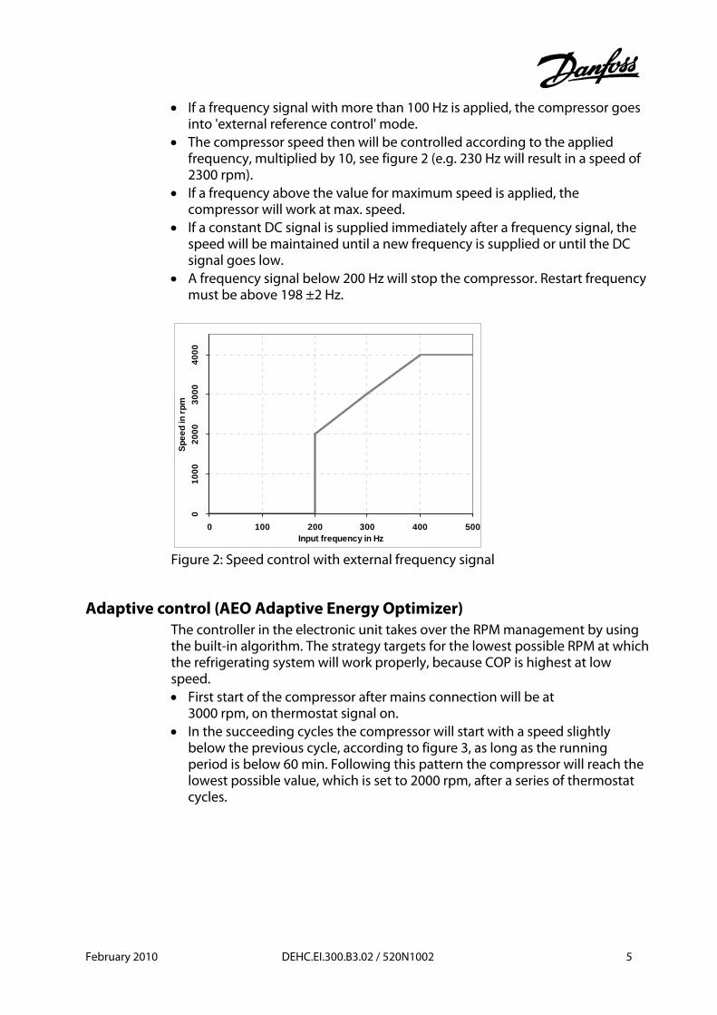
• If a frequency signal with more than 100 Hz is applied, the compressor goes into 'external reference control' mode.
• The compressor speed then will be controlled according to the applied frequency, multiplied by 10, see figure 2 (e.g. 230 Hz will result in a speed of 2300 rpm).
• If a frequency above the value for maximum speed is applied, the compressor will work at max. speed.
• If a constant DC signal is supplied immediately after a frequency signal, the speed will be maintained until a new frequency is supplied or until the DC signal goes low.
• A frequency signal below 200 Hz will stop the compressor. Restart frequency must be above 198 ±2 Hz.
010
0020
0030
0040
00
0 100 200 300 400 500Input frequency in Hz
Spee
d in
rpm
Figure 2: Speed control with external frequency signal
Adaptive control (AEO Adaptive Energy Optimizer) The controller in the electronic unit takes over the RPM management by using the built-in algorithm. The strategy targets for the lowest possible RPM at which the refrigerating system will work properly, because COP is highest at low speed. • First start of the compressor after mains connection will be at
3000 rpm, on thermostat signal on. • In the succeeding cycles the compressor will start with a speed slightly
below the previous cycle, according to figure 3, as long as the running period is below 60 min. Following this pattern the compressor will reach the lowest possible value, which is set to 2000 rpm, after a series of thermostat cycles.

February 2010 DEHC.EI.300.B3.02 / 520N1002 6
4000
3628
3320
3060
2838
2646
2478
2330
2199
2082
2000
2000
2000
2000
2000
2000
2000
2000
2000
2000
3000
2786
2601
2438
2295
2168
2054
2000
2000
2000
2000
2000
2000
2000
2000
2000
2000
2000
2000
2000
2500
2350
2216
2097
2000
2000
2000
2000
2000
2000
2000
2000
2000
2000
2000
2000
2000
2000
2000
1500
2000
2500
3000
3500
4000
4500
0 1 2 3 4 5 6 7 8 9 10
Number of thermostat breaks
Spee
d in
rpm
Figure 3: AEO step down examples • If the running period however exceeds 60 minutes, the speed is increased
according to the scheme in figure 4. • After a total duty cycle of 75 minutes the control unit will increase the speed
first time, then successively every 15 minutes until the max. speed is reached. Following this pattern the compressor will reach the maximum speed within a certain time, depending on the start speed, if not recieving an 'off' signal. This increase will normally occur at high ambient temperature or at loading of a freezer for freezing.
3000 3000 3000 3000
3214
4000 4000 4000 4000 4000 4000
2750 2750 2750 2750
2931
4000 4000 4000 4000 4000
2500 2500 2500 25002650
3638
4000 4000 4000 4000 4000
2250 2250 2250 22502373
3134
4000 4000 4000 4000 4000
2000 2000 2000 20002097
2671
3677
4000 4000 4000 4000
1000
1500
2000
2500
3000
3500
4000
4500
0:00 0:15 0:30 0:45 1:00 1:15 1:30 1:45 2:00 2:15 2:30Time in h:min
Spee
d in
rpm
RPM 3000
RPM 2750RPM 2500
RPM 2250RPM 2000
Figure 4: AEO step up examples
February 2010 DEHC.EI.300.B3.02 / 520N1002 7
Charge determination should be done at fixed speed, with a frequency according to the speed needed, like in the description at c).
Delivery: The compressors are delivered seperated from the electronic units. In quantities the compressors are delivered on standard Danfoss pallets with the dimensions 1144 x 800 mm containing 125 pcs BD150F or 80 pcs NLV-F per pallet. The electronic units are delivered in boxes or multiboxes.
Mounting: In general the compressors can be mounted as normal compressors. Ths generation of the variable speed compressors however has a slightly enlarged space need, in the area of the electronic unit. This may force the use of 'snap-on' mounting accessories. This space will be reduced in future electronic units generations. The electronic unit is mounted and fixed with two M 3.5 screws.
Approvals: Compressors are approved according to UL984 or EN 60335-2-34.
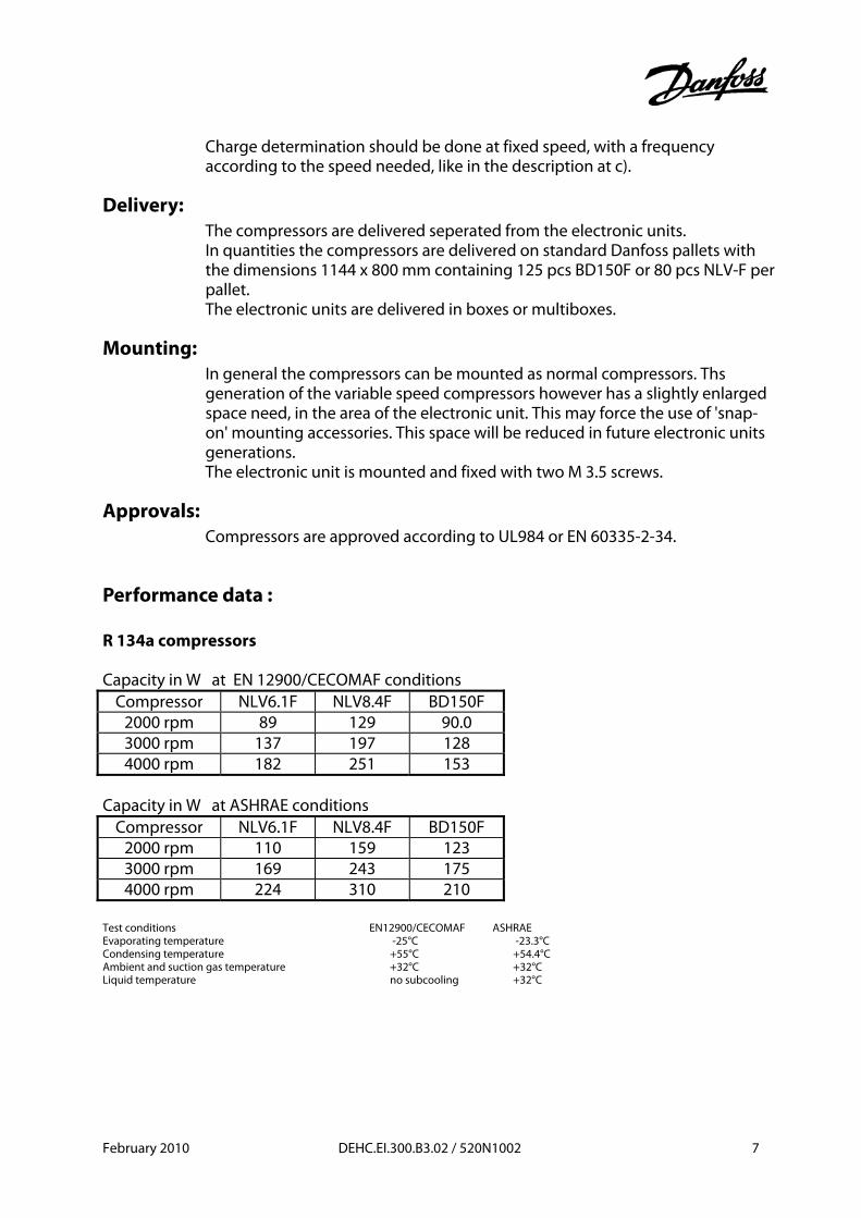
Performance data : R 134a compressors Capacity in W at EN 12900/CECOMAF conditions
Compressor NLV6.1F NLV8.4F BD150F 2000 rpm 89 129 90.0 3000 rpm 137 197 128 4000 rpm 182 251 153
Capacity in W at ASHRAE conditions
Compressor NLV6.1F NLV8.4F BD150F 2000 rpm 110 159 123 3000 rpm 169 243 175 4000 rpm 224 310 210
Test conditions EN12900/CECOMAF ASHRAE Evaporating temperature -25°C -23.3°C Condensing temperature +55°C +54.4°C Ambient and suction gas temperature +32°C +32°C Liquid temperature no subcooling +32°C

February 2010 DEHC.EI.300.B3.02 / 520N1002 8
G eneral data: Refrigerant R134a Compressor NLV6.1F NLV8.4F BD150F Code number 105G5660 105G5960 102G4784 Electronic unit 105N4212 105N4212 105N4220 Application MBP/LBP MBP/LBP LBP Evap. temp. range -35 to 7.2 -35 to 7.2 -35 to -10 Voltage range 80-140 80-140 160-254 AC
250-350 DC Starting torque HST HST HST Max ambient 43 °C 43 °C 43 °C Compressor cooling Fan 1.5 m/s Fan 1.5 m/s static Displacement cm3 6.13 8.35 6.49 Oil quantity cm3 320 320 280 Max. refrig. charge kg 0.4 0.4 0.4 Weight compressor / electronic unit kg
10.5 0.4
10.5 0.4
8.0 0.4
Height mm A B
203 197
203 197
173 169
Suction conn. C 8.2 8.2 6.2 Process conn. D 6.5 6.5 6.2 Discharge conn. E 6.5 6.5 5
157
6612
0
102 96117
297151
°20
°
45°
170178
70 100
Ø16
186204
ø9
3510
5
107
105
BA
30°
31.5°28°
176230C D
E
8394
A B
C
ED
8642
25° 35° 15°
47°27°51°
6.54
(166
)"
2.83
(72)
"4.72
(120
)"
4.45"(113)
5.00"(127)
4.69"(119)
3.35
"(85
)
2.13
"(5
4)
8.10"(205)
8.03"(204)
6.70"(170)
3.68
"(93
.5)
10.24"(260)
2.97
"(75
.5)
4.04
"(102
.5)
6.50"(165)
7.32"(186)
2.76
"(70
)
ø0.63"(16)
1.38
"(3
5)
ø0. "75 (19)
ø0.38"(9.7)
4.00
"(10
1.6)
5.20
"(13
2)
Figure 5: BD150F dimensions Figure 6: NLV dimensions

February 2010 DEHC.EI.300.B3.02 / 520N1002 9
Test equipment specifications:
Power consumption Because of a current shape different from standard compressors, as described more in detail in 'Current consumption shape', measuring equipment for energy consumption has to meet extended specifications. The higher frequency parts of the current give a demand for a bandwidth of at least 5 kHz for the energy consumption measurement equipment, to get accurate measurements. We recommend following data: Minimum bandwidth 10 kHz Power factor capability <0.2 Peak current capability 25 A Results coming from equipment with unsatisfactory bandwidth are not pre-dictable. A systematic deviation of several percent is easily possible to get, resulting in higher or lower values.
Speed When testing compressors on a calorimeter, an accurate frequency signal source has to be used, e.g. a laboratory frequency generator. Testing at a different speed, slightly higher, gives remarkable differences, and non comparable results. When testing at lowest possible speed, 2000 rpm, the control signal has to be put above the startup frequency of 198 ±2 Hz, then carefully adjusted down to 200 Hz, because the electronic unit stops the motor below 200 Hz. In this way a test at 2000 rpm to 2005 rpm should be possible. For charge determination in appliances, the speed should be fixed with a frequency signal source also.
Current consumption shape: The PM motors used in the TLV compressors are feed with a PWM modulated switched DC current. The DC part is feed via a rectifier bridge. This gives current peaks with a shape very different from a sine curve resulting in a remarkable power factor. Test equipment should be capable of measuring up to 10 kHz to get accurate results. Digital wattmeters usually have a bandwidth of 10 kHz or more.
Voltage stabilization: When operating a single appliance with a variable speed compressor on an automatic voltage stabilizer in a laboratory, the stabilizer can produce very strong voltage fluctuations, because of the current shape being very different to sine. Using an additional load, e.g. a normal incandescent lamp or other resistant load, the stabilizer should work normal again.

DEHC.EI.300.B3.02/520N1002 Produced by Danfoss Compressors, DEHC6093, 02.2010
Danfoss can accept no responsibility for possible errors in catalogues, brochures and other printed material. Danfoss reserves the right to alter its products without notice. This also applies to products already on order provided that such alterations can be made without subsequential changes being necessary in specifications already agreed.All trademarks in this material are property of the respective companies. Danfoss and the Danfoss logotype are trademarks of Danfoss A/S. All rights reserved.
Danfoss Compressors GmbH • Mads-Clausen-Str. 7 • D-24939 Flensburg / Germany • Tel: +49 (0461) 4941-0 • Fax: +49 (0461) 44715 • compressors.danfoss.com