vapor deposition of platinum alloyed nickel aluminide coatings
TRANSCRIPT
201 (2006) 2326–2334www.elsevier.com/locate/surfcoat
Surface & Coatings Technology
Vapor deposition of platinum alloyed nickel aluminide coatings
Z. Yu ⁎, K.P. Dharmasena, D.D. Hass, H.N.G. Wadley
Department of Materials Science and Engineering University of Virginia Charlottesville, VA 22903, USA
Received 14 April 2005; accepted in revised form 3 April 2006Available online 19 June 2006
Abstract
Platinum-doped NiAl coatings are widely used to increase the oxidation resistance of superalloys. These coatings are usually synthesized by a solidstate reaction-diffusion process conducted at high temperature. It requires the chemical vapor deposition of aluminum on a nickel rich superalloysubstrate that has been pre-coated with several microns of electrodeposited platinum. Here, we show that an electron beam directed vapor deposition(EB-DVD) technique can be used to deposit well bonded, structurally and chemically homogeneous NiAlPt bond coats of any composition ontosuperalloy substrates. The approach utilized a high voltage, rapid scan frequency electron beam to independently heat elemental nickel, aluminum andplatinum melt pools to create three closely spaced vapor plumes. These vapor plumes were then entrained in an inert gas jet flow, which mixed anddirected them to a substrate. By adjusting the electron beam current applied to each elemental source, homogeneous, dense, Pt alloyed β-phase NiAlcoatings could be synthesized at substrate temperatures of 1050 °C. The width of the substrate–coating interdiffusion zone was controlled by thedeposition temperature and time.© 2006 Elsevier B.V. All rights reserved.
Keywords: Thermal barrier coating; Bond coat; NiAlPt; EB-DVD
1. Introduction
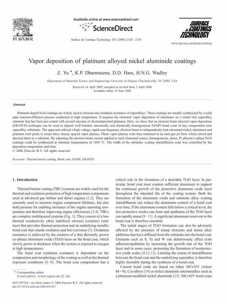
Thermal barrier coating (TBC) systems are widely used for thethermal and oxidation protection of high temperature componentsused in advanced gas turbine and diesel engines [1,2]. They arecurrently used to increase engine component lifetimes, but alsohold promise for enabling increases of the engine operating tem-perature and therefore improving engine efficiencies [3,4]. TBCsare complex multilayered systems (Fig. 1). They consist of a lowthermal conductivity yttria stabilized zirconia (ceramic) outerlayer that provides thermal protection and an underlying metallicbond coat that retards oxidation and hot corrosion [5]. Oxidationresistance is achieved by the creation of a thin thermally grown(α-phase) aluminum oxide (TGO) layer on the bond coat, whichslowly grows in thickness when the system is exposed to oxygenat high temperatures.
The bond coat oxidation resistance is dependent on thecomposition andmorphology of the coating aswell as the thermalexposure conditions [6–8]. The bond coat composition has a
⁎ Corresponding author.E-mail address: [email protected] (Z. Yu).
0257-8972/$ - see front matter © 2006 Elsevier B.V. All rights reserved.doi:10.1016/j.surfcoat.2006.04.020
critical role in the formation of a desirable TGO layer. In par-ticular, bond coat must contain sufficient aluminum to supportthe continued growth of the protective aluminum oxide layerthroughout the intended life of the coating system. Both theformation of the aluminum oxide and substrate alloy–coatinginterdiffusion can reduce the aluminum content of a bond coatover time. If the aluminum content falls below a critical level, theless protective oxides can form and spallation of the TGO layercan rapidly ensue [9–11]. A significant aluminum reservoir in thebond coat is therefore essential.
The initial stages of TGO formation can also be adverselyaffected by the presence of tramp elements and minor alloyadditions that have diffused from the substrate into the bond coat.Elements such as S, Ta and W can deleteriously effect scaleadhesion/spallation by increasing the growth rate of the TGOlayer and in some cases, promoting the formation of nonprotec-tive oxide scales [4,12,13]. Limiting the extent of interdiffusionbetween the bond coat and the underlying superalloy is thereforehighly desirable during the synthesis of a bond coat.
Current bond coats are based on either MCrAlY (whereM=Ni, Co) alloys [14] or nickel aluminide intermetallics such asa platinum-modified nickel aluminide [15]. MCrAlY bond coats
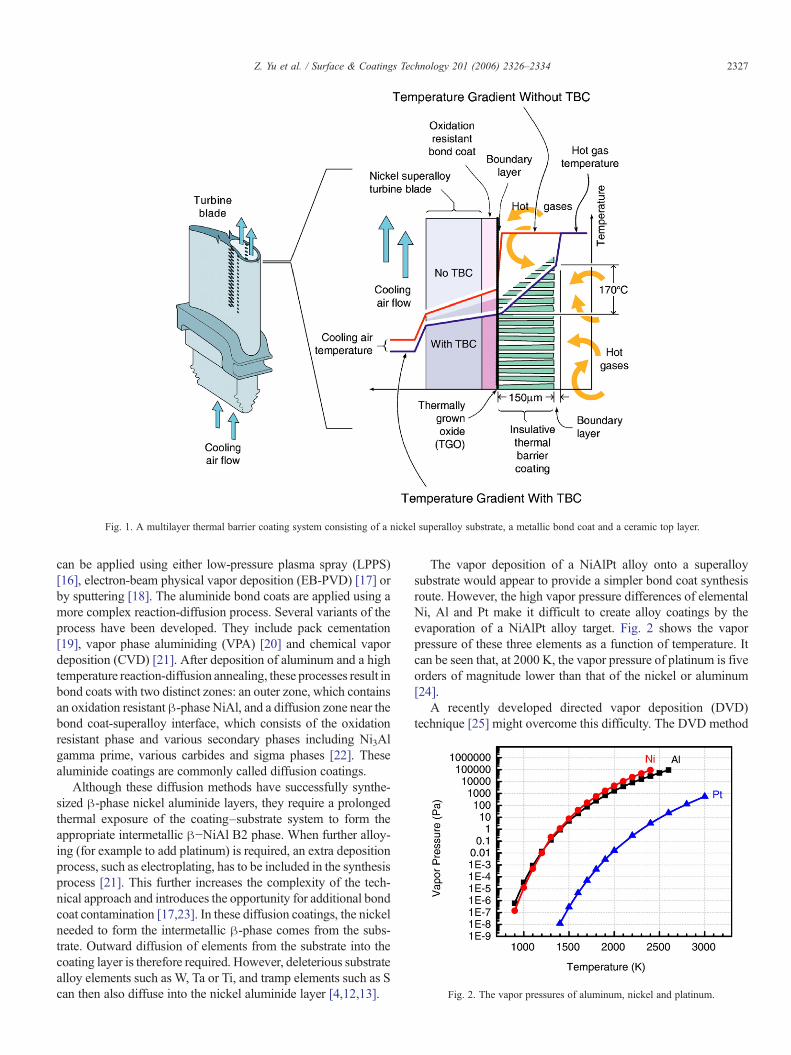
Fig. 1. A multilayer thermal barrier coating system consisting of a nickel superalloy substrate, a metallic bond coat and a ceramic top layer.
Fig. 2. The vapor pressures of aluminum, nickel and platinum.
2327Z. Yu et al. / Surface & Coatings Technology 201 (2006) 2326–2334
can be applied using either low-pressure plasma spray (LPPS)[16], electron-beam physical vapor deposition (EB-PVD) [17] orby sputtering [18]. The aluminide bond coats are applied using amore complex reaction-diffusion process. Several variants of theprocess have been developed. They include pack cementation[19], vapor phase aluminiding (VPA) [20] and chemical vapordeposition (CVD) [21]. After deposition of aluminum and a hightemperature reaction-diffusion annealing, these processes result inbond coats with two distinct zones: an outer zone, which containsan oxidation resistant β-phase NiAl, and a diffusion zone near thebond coat-superalloy interface, which consists of the oxidationresistant phase and various secondary phases including Ni3Algamma prime, various carbides and sigma phases [22]. Thesealuminide coatings are commonly called diffusion coatings.
Although these diffusion methods have successfully synthe-sized β-phase nickel aluminide layers, they require a prolongedthermal exposure of the coating–substrate system to form theappropriate intermetallic β−NiAl B2 phase. When further alloy-ing (for example to add platinum) is required, an extra depositionprocess, such as electroplating, has to be included in the synthesisprocess [21]. This further increases the complexity of the tech-nical approach and introduces the opportunity for additional bondcoat contamination [17,23]. In these diffusion coatings, the nickelneeded to form the intermetallic β-phase comes from the subs-trate. Outward diffusion of elements from the substrate into thecoating layer is therefore required. However, deleterious substratealloy elements such as W, Ta or Ti, and tramp elements such as Scan then also diffuse into the nickel aluminide layer [4,12,13].
The vapor deposition of a NiAlPt alloy onto a superalloysubstrate would appear to provide a simpler bond coat synthesisroute. However, the high vapor pressure differences of elementalNi, Al and Pt make it difficult to create alloy coatings by theevaporation of a NiAlPt alloy target. Fig. 2 shows the vaporpressure of these three elements as a function of temperature. Itcan be seen that, at 2000 K, the vapor pressure of platinum is fiveorders of magnitude lower than that of the nickel or aluminum[24].
A recently developed directed vapor deposition (DVD)technique [25] might overcome this difficulty. The DVD method

2328 Z. Yu et al. / Surface & Coatings Technology 201 (2006) 2326–2334
utilizes a differentially pumped, high voltage electron beam guncapable of operating in a high-pressure environment together withan inert gas jet to entrain and deposit the vapor. By using a highscan frequency electron beam gun, several different materials canbe co-evaporated at independently controllable rates. This can beaccomplished from sources placed within the inert gas jet, whichenables the creation of an alloy vapor plume of controllablecomposition by independently controlling the evaporation rate ofeach source. By using a low density, high velocity gas jet topromote gas phase vapor plume diffusion, a homogeneous com-position vapor flux can be achieved [26].
We have recently shown that the directed vapor depositiontechnique can be used to synthesize binary NiAl coatings byindependently evaporating nickel and aluminum elementalsources [27]. This enabled coating composition control and de-monstrated the growth of layers with a homogeneous β-phasestructure, few pores and only a small region of interdiffusion at thecoating–substrate interface. Here, we explore the extension of thisapproach to the deposition of ternary Al–Ni–Pt bond coats andshow that by independently evaporating the elemental sources, itis possible to synthesize NiAl+Pt alloy coatings even when thevapor pressure differences are high. We also show that dense,
Fig. 3. Schematic illustration of the directed vapor deposition processing system.
single-phase coatings can be created with minimal interdiffusionwith the substrate.
2. DVD process description
Several processes have emerged for combining the atomic andmolecular fluxes created by an evaporation process with rarefiedsupersonic gas jets [28–30]. In theDVDapproach, an inert gas jetis used to direct and transport an electron beam evaporated vaporplume to a substrate [31]. Fig. 3 shows a schematic illustration ofthis process. An annular nozzle in combination with a fixedupstream pressure (i.e. the gas pressure prior to its entrance intothe processing chamber), Pu, of at least twice that of the chamberpressure, Po, was used to form the supersonic gas jet [32,33]. Thecrucible used to hold the source materials were placed in the exitthroat of the nozzle. These source materials were then heated byan electron beam to form a melt pool with a vapor plume above.The inert gas stream then transported the vapor from the nozzle ina gas jet whose initial cross-sectional area was comparable to thatof the nozzle. Using appropriate jet flow conditions, most of thevapor can be confined within the jet and directed to the substrate.The carrier gas molecular weight (compared to that of the vapor)
It is possible to evaporate from four individual source materials (two shown).
2329Z. Yu et al. / Surface & Coatings Technology 201 (2006) 2326–2334
and the carrier gas speed control the effectiveness of the vaporatom redirection (via binary collisions) and transport to the sub-strate [25]. Optimizing system parameters such as the nozzlediameter, gas flow rate and pumping speed enable a relativelyuniform, high efficiency deposition of the evaporant onto asubstrate [31].
The system used here utilized a differential pumped electronbeam gun (EB-gun) modified to function in a high-pressureenvironment. A high accelerating voltage (60 kV) e-beam gunwas used to reduce the electron scattering cross section, whichthen facilitates efficient beam propagation in relatively high-pressure environments [34,35]. The high-speed (100 kHz) e-beamscanning system, combined with a small beam spot diameter(b0.5 mm) allowed a multisource crucible to be used to create analloy vapor plume from its constituent metal components orbinary combinations of the metals with similar vapor pressures.Up to four of 3.2 mm diameter sources could be simultaneouslyevaporated in the DVD chamber. In practice, the electron beamwas jumped among each of the sources and the relative dwell timeon each source was adjusted to control the individual melt pooltemperatures and therefore the evaporation rate. For the high scanfrequencies used here, this is equivalent to a splitting of the totalelectron beam current into three branches, each of which isapplied to heat one source continuously (Fig. 4). By adjusting thedwell times of the beam, the individual evaporation rates of thethree Ni, Al and Pt sources, and the average plume stoichiometrycould be controlled over a wide range of coating compositions.
By adjusting the flow conditions used to create the jet, highdeposition rates were achievable with a relatively low power
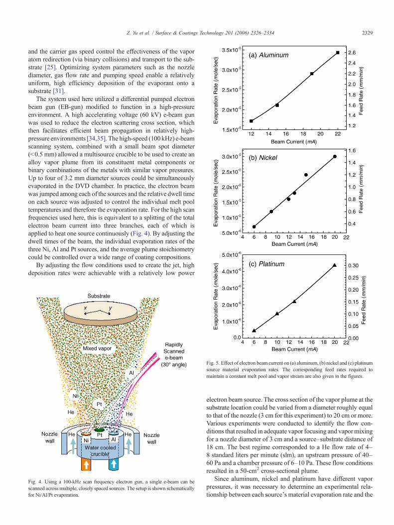
Fig. 4. Using a 100-kHz scan frequency electron gun, a single e-beam can bescanned across multiple, closely spaced sources. The setup is shown schematicallyfor Ni/Al/Pt evaporation.
Fig. 5. Effect of electron beam current on (a) aluminum, (b) nickel and (c) platinumsource material evaporation rates. The corresponding feed rates required tomaintain a constant melt pool and vapor stream are also given in the figures.
electron beam source. The cross section of the vapor plume at thesubstrate location could be varied from a diameter roughly equalto that of the nozzle (3 cm for this experiment) to 20 cm or more.Various experiments were conducted to identify the flow con-ditions that resulted in adequate vapor focusing and vapormixingfor a nozzle diameter of 3 cm and a source–substrate distance of18 cm. The best regime corresponded to a He flow rate of 4–8 standard liters per minute (slm), an upstream pressure of 40–60 Pa and a chamber pressure of 6–10 Pa. These flow conditionsresulted in a 50-cm2 cross-sectional plume.
Since aluminum, nickel and platinum have different vaporpressures, it was necessary to determine an experimental rela-tionship between each source's material evaporation rate and the
2330 Z. Yu et al. / Surface & Coatings Technology 201 (2006) 2326–2334
electron beam current applied to it. Fig. 5 shows the dependenceof the evaporation rate (and the equivalent source rod feed rate)upon electron beam current for the three elemental sources.These relationships enabled identification of the appropriatecombinations of beam current (dwell time) to achieve a desiredelemental source evaporation rate and therefore a target coatinglayer composition.
Commercial RENÉ N5 superalloy [36] coupons with adiameter of 2.54 cm were used as the substrates. A flat-plateheater with tungsten filament was used to heat the substrate fromthe backside. The substrates were pre-heated to 450 °C for 1 h toclean the surface and then heated to 1050 °C for deposition. Ahelium gas jet with a flow rate of 7 slm was used. This corres-ponded to an upstream pressure of 56 Pa and a chamber pressureof 8.9 Pa. The deposition duration was varied from 30 to 40 min.Using a 3 kW beam power, the three source materials combinedevaporation rate was about 2.7×10⁻³ mol/min and the measureddeposition rate was 1.0±0.2 μm/min. After the deposition pro-cess, the samples were cooled to ambient within the depositionchamber in an inert gas environment. The resulting as depositedalloy coating morphologies were observed using scanning elec-tron microscopy (SEM) and the coating compositions wereanalyzed using energy dispersive spectroscopy (EDS) measure-ments. The coating phase structures were identified with standardX-ray diffraction techniques.
3. Results and discussion
A series of initial coating trials were conducted to identify thepreferred deposition temperature. Earlier studies have indicatedthat the deposition of pore-free NiAl could be achieved at adeposition temperature of 1000 °C and a deposition rate of 0.5–1 μm/min [27]. In the platinum-modified system, these conditionsresulted in coatings containing a significant volume fraction ofisolated pores that was thought to be a result of the poor migration
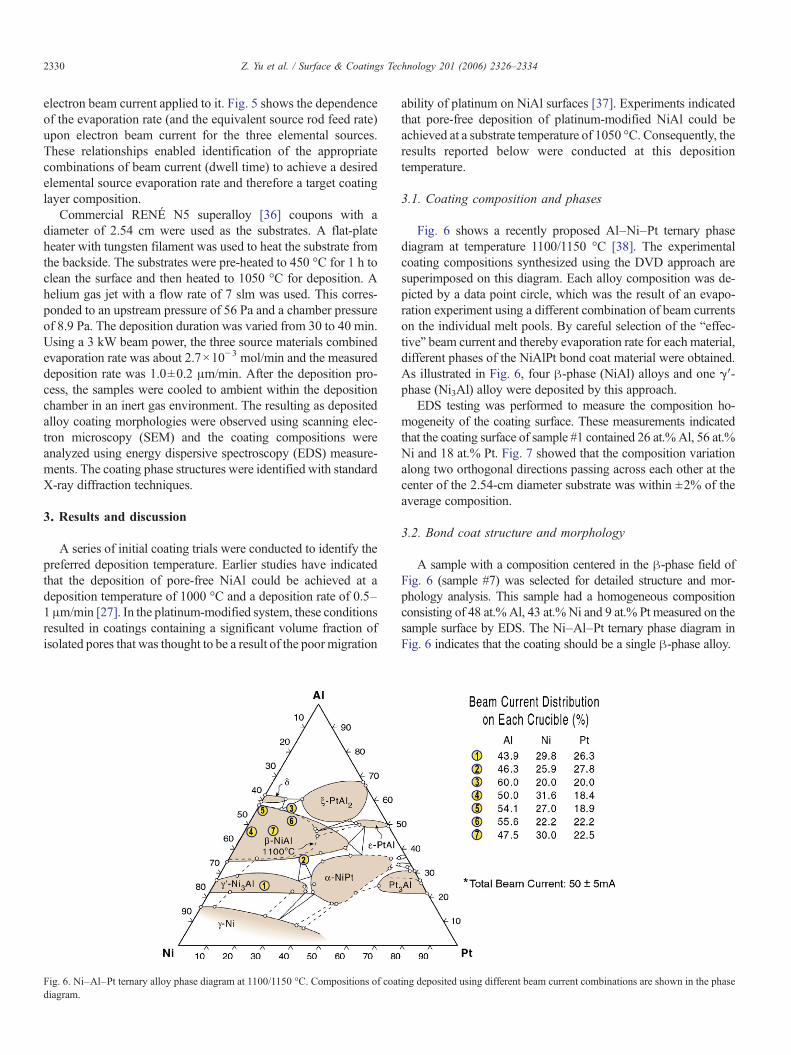
Fig. 6. Ni–Al–Pt ternary alloy phase diagram at 1100/1150 °C. Compositions of coadiagram.
ability of platinum on NiAl surfaces [37]. Experiments indicatedthat pore-free deposition of platinum-modified NiAl could beachieved at a substrate temperature of 1050 °C. Consequently, theresults reported below were conducted at this depositiontemperature.
3.1. Coating composition and phases
Fig. 6 shows a recently proposed Al–Ni–Pt ternary phasediagram at temperature 1100/1150 °C [38]. The experimentalcoating compositions synthesized using the DVD approach aresuperimposed on this diagram. Each alloy composition was de-picted by a data point circle, which was the result of an evapo-ration experiment using a different combination of beam currentson the individual melt pools. By careful selection of the “effec-tive” beam current and thereby evaporation rate for each material,different phases of the NiAlPt bond coat material were obtained.As illustrated in Fig. 6, four β-phase (NiAl) alloys and one γ′-phase (Ni3Al) alloy were deposited by this approach.
EDS testing was performed to measure the composition ho-mogeneity of the coating surface. These measurements indicatedthat the coating surface of sample #1 contained 26 at.%Al, 56 at.%Ni and 18 at.% Pt. Fig. 7 showed that the composition variationalong two orthogonal directions passing across each other at thecenter of the 2.54-cm diameter substrate was within ±2% of theaverage composition.
3.2. Bond coat structure and morphology
A sample with a composition centered in the β-phase field ofFig. 6 (sample #7) was selected for detailed structure and mor-phology analysis. This sample had a homogeneous compositionconsisting of 48 at.% Al, 43 at.% Ni and 9 at.% Pt measured on thesample surface by EDS. The Ni–Al–Pt ternary phase diagram inFig. 6 indicates that the coating should be a single β-phase alloy.
ting deposited using different beam current combinations are shown in the phase
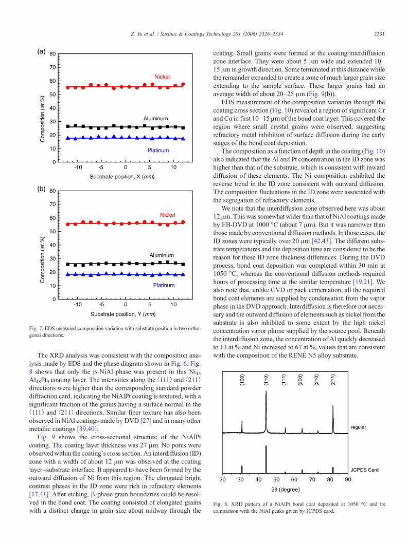
Fig. 8. XRD pattern of a NiAlPt bond coat deposited at 1050 °C and itscomparison with the NiAl peaks given by JCPDS card.
Fig. 7. EDS measured composition variation with substrate position in two ortho-gonal directions.
2331Z. Yu et al. / Surface & Coatings Technology 201 (2006) 2326–2334
The XRD analysis was consistent with the composition ana-lysis made by EDS and the phase diagram shown in Fig. 6. Fig.8 shows that only the β-NiAl phase was present in this Ni43Al48Pt9 coating layer. The intensities along the ⟨111⟩ and ⟨211⟩directions were higher than the corresponding standard powderdiffraction card, indicating the NiAlPt coating is textured, with asignificant fraction of the grains having a surface normal in the⟨111⟩ and ⟨211⟩ directions. Similar fiber texture has also beenobserved in NiAl coatings made by DVD [27] and in many othermetallic coatings [39,40].
Fig. 9 shows the cross-sectional structure of the NiAlPtcoating. The coating layer thickness was 27 μm. No pores wereobservedwithin the coating's cross section.An interdiffusion (ID)zone with a width of about 12 μm was observed at the coatinglayer–substrate interface. It appeared to have been formed by theoutward diffusion of Ni from this region. The elongated brightcontrast phases in the ID zone were rich in refractory elements[17,41]. After etching, β-phase grain boundaries could be resol-ved in the bond coat. The coating consisted of elongated grainswith a distinct change in grain size about midway through the
coating. Small grains were formed at the coating/interdiffusionzone interface. They were about 5 μm wide and extended 10–15 μm in growth direction. Some terminated at this distance whilethe remainder expanded to create a zone of much larger grain sizeextending to the sample surface. These larger grains had anaverage width of about 20–25 μm (Fig. 9(b)).
EDS measurement of the composition variation through thecoating cross section (Fig. 10) revealed a region of significant Crand Co in first 10–15 μm of the bond coat layer. This covered theregion where small crystal grains were observed, suggestingrefractory metal inhibition of surface diffusion during the earlystages of the bond coat deposition.
The composition as a function of depth in the coating (Fig. 10)also indicated that the Al and Pt concentration in the ID zone washigher than that of the substrate, which is consistent with inwarddiffusion of these elements. The Ni composition exhibited thereverse trend in the ID zone consistent with outward diffusion.The composition fluctuations in the ID zone were associated withthe segregation of refractory elements.
We note that the interdiffusion zone observed here was about12μm.Thiswas somewhat wider than that ofNiAl coatingsmadeby EB-DVD at 1000 °C (about 7 μm). But it was narrower thanthosemade by conventional diffusionmethods. In those cases, theID zones were typically over 20 μm [42,43]. The different subs-trate temperatures and the deposition time are considered to be thereason for these ID zone thickness differences. During the DVDprocess, bond coat deposition was completed within 30 min at1050 °C, whereas the conventional diffusion methods requiredhours of processing time at the similar temperature [19,21]. Wealso note that, unlike CVD or pack cementation, all the requiredbond coat elements are supplied by condensation from the vaporphase in the DVD approach. Interdiffusion is therefore not neces-sary and the outward diffusion of elements such as nickel from thesubstrate is also inhibited to some extent by the high nickelconcentration vapor plume supplied by the source pool. Beneaththe interdiffusion zone, the concentration of Al quickly decreasedto 13 at.% and Ni increased to 67 at.%, values that are consistentwith the composition of the RENÉ N5 alloy substrate.
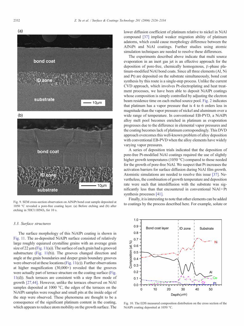
Fig. 10. The EDS measured composition distribution on the cross section of theNiAlPt coating deposited at 1050 °C.
Fig. 9. SEM cross-section observation on AlNiPt bond coat sample deposited at1050 °C revealed a pore-free coating layer. (a) Before etching and (b) afteretching in 5HCl:1HNO3 for 10 s.
2332 Z. Yu et al. / Surface & Coatings Technology 201 (2006) 2326–2334
3.3. Surface structures
The surface morphology of this NiAlPt coating is shown inFig. 11. The as-deposited NiAlPt surface consisted of relativelylarge roughly equiaxed crystalline grains with an average grainsize of 22μm (Fig. 11(a)). The surface of each grain had a groovedsubstructure (Fig. 11(b)). The grooves changed direction andangle at the grain boundaries and deeper grain boundary grooveswere observed at these locations (Fig. 11(c)). Further observationsat higher magnification (30,000×) revealed that the grooveswere actually part of terrace structure on the coating surface (Fig.11(d)). Such terraces are consistent with a step flow mode ofgrowth [27,44]. However, unlike the terraces observed on NiAlsamples deposited at 1000 °C, the edges of the terraces on theNiAlPt samples were rougher and small pits at the inside edge ofthe step were observed. These phenomena are thought to be aconsequence of the significant platinum content in the coating,which appears to reduce atommobility on the growth surface. The
lower diffusion coefficient of platinum relative to nickel in NiAlcompound [37] implied weaker migration ability of platinumadatoms, which could cause morphology difference between theAlNiPt and NiAl coatings. Further studies using atomicsimulation techniques are needed to resolve these differences.
The experiments described above indicate that multi sourceevaporation in an inert gas jet is an effective approach for thedeposition of pore-free, chemically homogenous, β-phase pla-tinum-modified NiAl bond coats. Since all three elements (Al, Niand Pt) are deposited on the substrate simultaneously, bond coatsynthesis by this route is a single-step process. Unlike the currentCVD approach, which involves Pt-electroplating and heat treat-ment processes, we have been able to deposit NiAlPt coatingswhose composition is simply controlled by adjusting the electronbeam residence time on each melted source pool. Fig. 2 indicatesthat platinum has a vapor pressure that is 4 to 6 orders less inmagnitude than the vapor pressure of nickel and aluminum over awide range of temperature. In conventional EB-PVD, a NiAlPtalloy melt pool becomes enriched in platinum as evaporationprogresses due to the difference in elemental vapor pressures andthe coating becomes lack of platinum correspondingly. This DVDapproach overcomes this well-known problem of alloy depositionwith conventional EB-PVDwhen the alloy elements have widelyvarying vapor pressures.
A series of deposition trials indicated that the deposition ofpore-free Pt-modified NiAl coatings required the use of slightlyhigher growth temperatures (1050 °C) compared to those neededfor the growth of pore-free NiAl. We suspect that Pt increases theactivation barriers for surface diffusion during NiAl film growth.Atomistic simulations are needed to resolve this issue [37]. Ne-vertheless, the combination of growth temperature and depositionrate were such that interdiffusion with the substrate was sig-nificantly less than that encountered in conventional NiAl+Ptsynthesis processes [41].
Finally, it is interesting to note that other elements can be addedto coatings by the process described here. For example, solute or

Fig. 11. Surface morphologies of NiAlPt bond coats deposited at 1050 °C. (a) NiAlPt surface consists of crystalline grains with average grain size 22 μm. (b) Grainsurface morphology at 10,000× magnification. (c) The strikes change their direction and twist at the grain boundary. (d) Grain surface morphology at 30,000×magnification.
2333Z. Yu et al. / Surface & Coatings Technology 201 (2006) 2326–2334
precipitation strengthening by the addition of elements such asHf,Cr, Zr or Y might enable increases in the yield/creep strength ofthe coatings [1,4,45]. The vapor pressures of these elements varywidely, but the multi evaporation source approach described hereholds some promise for expanding the range of compositions thatcan be successfully deposited.
4. Conclusion
We have utilized a multi source evaporation method togetherwith gas jet enhanced mixing to deposit NiAlPt coatings ofcontrolled composition and morphology. The approach utilizesclosely spaced multisource crucible and an electron beam whosedwell time on individual source materials can be modified tocontrol the individual source evaporation rate. An inert gas jetflow promotes vapor mixing and the deposition of homogeneous,pore-free NiAlPt coatings without the assistance of post-depo-sition heat treatments. Coatings with a single β-phase structureand no surface contamination by substrate alloy elements havebeen fabricated.
Acknowledgement
We are grateful to Profs. Carlos Levi, Anthony Evans andDavid Clarke of University of California, Santa Barbara, Dr.David Wortman, GE Corporate R&D, Schenectady, New York,and Yossi Marciano, Nuclear Research Center-Negev, Israel foruseful discussions. We thank Prof. Brian Gleeson, Iowa StateUniversity for granting permission to use his Ni–Al–Pt phasediagram. This work was supported by an ONR MURI programon Prime Reliant Coatings (Program Manager, Steve Fishman),ONR Contract # N00014-00-1-0438.
References
[1] C.G. Levi, Curr. Opin. Solid State Mater. Sci. 8 (2004) 77.[2] Coatings for High-Temperature Structural Materials, National Research
Council Report, National Academy Press, Washington, DC, 1996.[3] G.W. Goward, Surf. Coat. Technol. 108/109 (1998) 73.[4] N.P. Padture, M. Gell, E.H. Jordan, Science 296 (2002) 280.[5] B.J. Gill, R.C. Tucker Jr., Mater. Sci. Technol. 2 (1986) 207.[6] V.K. Tolpygo, D.R. Clarke, Acta Mater. 48 (2000) 3283.

2334 Z. Yu et al. / Surface & Coatings Technology 201 (2006) 2326–2334
[7] P. Kofstad, High Temperature Corrosion, Elsevier Applied Science,London, 1988.
[8] U.R. Evans, The Corrosion and Oxidation of Metals, Matthew Arnold,London, 1960.
[9] E.A.G. Shillington, D.R. Clarke, Acta Mater. 47 (1999) 1297.[10] M. Gell, K. Vaidyanathan, B. Barber, J. Cheng, E. Jordan, Metall. Mater.
Trans., A Phys. Metall. Mater. Sci. 30 (1999) 427.[11] M.R. Brickey, J.L. Lee, Oxid. Met. 54 (2000) 237.[12] B.A. Pint, I.G. Wright, W.Y. Lee, et al., Mater. Sci. Eng., A Struct. Mater.:
Prop. Microstruct. Process. 245 (1998) 201.[13] J.G. Smeggil, Mater. Sci. Eng., A Struct. Mater.: Prop. Microstruct.
Process. 87 (1987) 261.[14] R. Darolia, U.S. Patent 6,255,001, July 2001.[15] R. Mevrel, C. Duret, R. Pichoir, Mater. Sci. Technol. 2 (1986) 201.[16] G.Y. Kim, W.Y. Lee, J.A. Haynes, T.R. Watkins, Metall. Mater. Trans., A
Phys. Metall. Mater. Sci. 32 (2001) 615.[17] D.R. Mumm, A.G. Evans, Acta Mater. 48 (2000) 1815.[18] R.S. Parzuchowski, Thin Solid Films 45 (1977) 349.[19] S.R. Choi, J.W. Hutchinson, A.G. Evans, Mech. Mater. 31 (1999) 447.[20] P.K. Wright, A.G. Evans, Curr. Opin. Solid State Mater. Sci. 4 (1999) 255.[21] W.Y. Lee, Y. Zhang, I.G. Wright, B.A. Pint, P.K. Liaw, Metall. Mater.
Trans., A Phys. Metall. Mater. Sci. 29 (1998) 833.[22] M.J. Stiger, N.M. Yanar, M.G. Topping, F.S. Pettit, G.H. Meier, Metallk 90
(1999) 1069.[23] Y. Zhang, W.Y. Lee, J.A. Haynes, I.G. Wright, B.A. Pint, K.M. Cooley, P.K.
Liaw, Metall. Mater. Trans., A Phys. Metall. Mater. Sci. 30 (1999) 2679.[24] Vapor pressure of the chemical elements, Nesme‘i’anov, An. N. (Andrei
Nikolaevich), 1911-(1963), in: R. Gary (Ed.), Elsevier Pub. Co, Amsterdam,1963.
[25] D.D. Hass, K. Dharmasena, H.N.G. Wadley, International Conference onHigh-Power Electron Beam Technology, vol. 8–1, 2002.
[26] D.D. Hass, P.A. Parrish, H.N.G.Wadley, J. Vac. Sci. Technol. A 16 (6) (1998)339.
[27] Z. Yu, D.D. Hass, H.N.G. Wadley, Mater. Sci. Eng., A Struct. Mater.: Prop.Microstruct. Process. 394 (2005) 43.
[28] B.L. Halpern, J.J. Schmidt, J. Vac. Sci. Technol. A 12 (1994) 1623.[29] J.J. Schmidt, B.L. Halpern, U.S. Patent 4788082 (1988).[30] J.F. Groves, H.N.G. Wadley, Compos., Part B Eng. 28B (1997) 57.[31] J.F. Groves, G. Mattausch, H. Morgner, D.D. Hass, H.N.G. Wadley, Surf.
Eng. 16 (2000) 461.[32] T.C. Adamson Jr., J.A. Nicholls, J. of the Aerospace Sciences, 26(1) (1959)
16.[33] J.F. Groves, “Directed vapor deposition”, PhD dissertation, p34–39, University
of Virginia (1998).[34] Y. Arata, Plasma, Electron, and Laser Beam Technology, Metals Park, OH,
ASM, 1986.[35] J.F. Groves, “Directed vapor deposition”, PhD dissertation, p60–63,
University of Virginia (1998).[36] J.A. Haynes, M.J. Lance, B.A. Pint, I.G.Wright, Surf. Coat. Technol. 146–147
(2001) 140.[37] Y. Minamino, Y. Koizumi, N. Tsuji, M. Morioka, K. Hirao, Y. Shirai, Sci.
Technol. Adv. Mater. 1 (2000) 237.[38] B. Gleeson, W. Wang, S. Hayashi, D. Sordelet, Mat. Sci. Forum 461–464
(2004) 213.[39] N. Schell, W. Matz, J. Bøttiger, J. Chevallier, P. Kringhøj, J. Appl. Phys. 91
(2002) 2037.[40] C.E. Murray, K.P. Rodbell, J. Appl. Phys. 89 (2001) 2337.[41] P.C. Patnaik, Mater. Manuf. Process. 4 (1989) 133.[42] B. Ning, M.E. Stevenson, M.L. Weaver, R.C. Bradt, Surf. Coat. Technol.
163–164 (2003) 112.[43] J. angenet, K. Stiller, Mater. Sci. Eng., A Struct. Mater.: Prop. Microstruct.
Process. 316 (2001) 182.[44] P. Gambardella, K. Kern, Surf. Sci. 475 (2001) L229.[45] J.R. Nicholls, MRS Bull. 28 (2003) 659.