vantage fcm booth - welcome to nordson...
TRANSCRIPT

Vantage� FCM Booth
Customer Product ManualPart 1051183A
Issued 6/04
NORDSON CORPORATION AMHERST, OHIO USA
For parts and technical support, call the Industrial CoatingSystems Customer Support Center at (800) 433-9319 or
contact your local Nordson representative.
This document is subject to change without notice.Check http://emanuals.nordson.com for the latest version.
Part 1051183A � 2004 Nordson Corporation
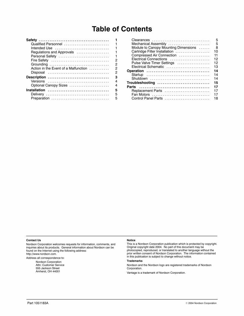
Table of ContentsSafety 1. . . . . . . . . . . . . . . . . . . . . . . . . . . . . . . . . . . . . . .
Qualified Personnel 1. . . . . . . . . . . . . . . . . . . . . . . . .Intended Use 1. . . . . . . . . . . . . . . . . . . . . . . . . . . . . .Regulations and Approvals 1. . . . . . . . . . . . . . . . . .Personal Safety 1. . . . . . . . . . . . . . . . . . . . . . . . . . . .Fire Safety 2. . . . . . . . . . . . . . . . . . . . . . . . . . . . . . . .Grounding 2. . . . . . . . . . . . . . . . . . . . . . . . . . . . . . . . .Action in the Event of a Malfunction 2. . . . . . . . . . .Disposal 2. . . . . . . . . . . . . . . . . . . . . . . . . . . . . . . . . .
Description 3. . . . . . . . . . . . . . . . . . . . . . . . . . . . . . . . . .Versions 4. . . . . . . . . . . . . . . . . . . . . . . . . . . . . . . . . .Optional Canopy Sizes 4. . . . . . . . . . . . . . . . . . . . . .
Installation 5. . . . . . . . . . . . . . . . . . . . . . . . . . . . . . . . . .Delivery 5. . . . . . . . . . . . . . . . . . . . . . . . . . . . . . . . . . .Preparation 5. . . . . . . . . . . . . . . . . . . . . . . . . . . . . . . .
Clearances 5. . . . . . . . . . . . . . . . . . . . . . . . . . . . . . . .Mechanical Assembly 5. . . . . . . . . . . . . . . . . . . . . . .Module to Canopy Mounting Dimensions 8. . . . . .Cartridge Filter Installation 10. . . . . . . . . . . . . . . . . . .Compressed Air Connection 11. . . . . . . . . . . . . . . . .Electrical Connections 12. . . . . . . . . . . . . . . . . . . . . .Pulse Valve Timer Settings 12. . . . . . . . . . . . . . . . . .Electrical Schematic 13. . . . . . . . . . . . . . . . . . . . . . . .
Operation 14. . . . . . . . . . . . . . . . . . . . . . . . . . . . . . . . . . .Startup 14. . . . . . . . . . . . . . . . . . . . . . . . . . . . . . . . . . .Shutdown 14. . . . . . . . . . . . . . . . . . . . . . . . . . . . . . . . .
Troubleshooting 15. . . . . . . . . . . . . . . . . . . . . . . . . . . . .Parts 17. . . . . . . . . . . . . . . . . . . . . . . . . . . . . . . . . . . . . . .
Replacement Parts 17. . . . . . . . . . . . . . . . . . . . . . . . .Fan Motors 17. . . . . . . . . . . . . . . . . . . . . . . . . . . . . . . .Control Panel Parts 18. . . . . . . . . . . . . . . . . . . . . . . . .
Contact UsNordson Corporation welcomes requests for information, comments, andinquiries about its products. General information about Nordson can befound on the Internet using the following address:http://www.nordson.com.Address all correspondence to:
Nordson CorporationAttn: Customer Service555 Jackson StreetAmherst, OH 44001
NoticeThis is a Nordson Corporation publication which is protected by copyright.Original copyright date 2004. No part of this document may bephotocopied, reproduced, or translated to another language without theprior written consent of Nordson Corporation. The information containedin this publication is subject to change without notice.
Trademarks
Nordson and the Nordson logo are registered trademarks of NordsonCorporation.
Vantage is a trademark of Nordson Corporation.

Vantage FCM Booth 1
Part 1051183A� 2004 Nordson Corporation
Vantage FCM Booth
Safety
Read and follow these safety instructions. Task-and equipment-specific warnings, cautions, andinstructions are included in equipmentdocumentation where appropriate.
Make sure all equipment documentation, includingthese instructions, is accessible to all personsoperating or servicing equipment.
Qualified Personnel Equipment owners are responsible for making surethat Nordson equipment is installed, operated, andserviced by qualified personnel. Qualifiedpersonnel are those employees or contractors whoare trained to safely perform their assigned tasks.They are familiar with all relevant safety rules andregulations and are physically capable ofperforming their assigned tasks.
Intended Use Use of Nordson equipment in ways other thanthose described in the documentation supplied withthe equipment may result in injury to persons ordamage to property.
Some examples of unintended use of equipmentinclude
� using incompatible materials
� making unauthorized modifications
� removing or bypassing safety guards orinterlocks
� using incompatible or damaged parts
� using unapproved auxiliary equipment
� operating equipment in excess of maximumratings
Regulations and Approvals Make sure all equipment is rated and approved forthe environment in which it is used. Any approvalsobtained for Nordson equipment will be voided ifinstructions for installation, operation, and serviceare not followed.
All phases of equipment installation must complywith all federal, state, and local codes.
Personal Safety To prevent injury follow these instructions.
� Do not operate or service equipment unless youare qualified.
� Do not operate equipment unless safetyguards, doors, or covers are intact andautomatic interlocks are operating properly. Donot bypass or disarm any safety devices.
� Keep clear of moving equipment. Beforeadjusting or servicing any moving equipment,shut off the power supply and wait until theequipment comes to a complete stop. Lock outpower and secure the equipment to preventunexpected movement.
� Relieve (bleed off) hydraulic and pneumaticpressure before adjusting or servicingpressurized systems or components.Disconnect, lock out, and tag switches beforeservicing electrical equipment.
� Obtain and read Material Safety Data Sheets(MSDS) for all materials used. Follow themanufacturer’s instructions for safe handlingand use of materials, and use recommendedpersonal protection devices.
� To prevent injury, be aware of less-obviousdangers in the workplace that often cannot becompletely eliminated, such as hot surfaces,sharp edges, energized electrical circuits, andmoving parts that cannot be enclosed orotherwise guarded for practical reasons.

Vantage FCM Booth2
Part 1051183A � 2004 Nordson Corporation
Fire Safety To avoid a fire or explosion, follow theseinstructions.
� Do not smoke, weld, grind, or use open flameswhere flammable materials are being used orstored.
� Provide adequate ventilation to preventdangerous concentrations of volatile materialsor vapors. Refer to local codes or your materialMSDS for guidance.
� Do not disconnect live electrical circuits whileworking with flammable materials. Shut offpower at a disconnect switch first to preventsparking.
� Know where emergency stop buttons, shutoffvalves, and fire extinguishers are located. If afire starts in a spray booth, immediately shut offthe spray system and exhaust fans.
� Clean, maintain, test, and repair equipmentaccording to the instructions in your equipmentdocumentation.
� Use only replacement parts that are designedfor use with original equipment. Contact yourNordson representative for parts informationand advice.
Grounding
WARNING: Operating faulty electrostaticequipment is hazardous and can causeelectrocution, fire, or explosion. Makeresistance checks part of your periodicmaintenance program. If you receive evena slight electrical shock or notice staticsparking or arcing, shut down all electricalor electrostatic equipment immediately. Donot restart the equipment until the problemhas been identified and corrected.
Grounding inside and around the booth openingsmust comply with NFPA requirements for Class 2,Division 1 or 2 Hazardous Locations. Refer toNFPA 33, NFPA 70 (NEC articles 500, 502, and516), and NFPA 77, latest conditions.
� All electrically conductive objects in the sprayareas shall be electrically connected to groundwith a resistance of not more than 1 megohmas measured with an instrument that applies atleast 500 volts to the circuit being evaluated.
� Equipment to be grounded includes, but is notlimited to, the floor of the spray area, operatorplatforms, hoppers, photoeye supports, andblow-off nozzles. Personnel working in thespray area must be grounded.
� There is a possible ignition potential from thecharged human body. Personnel standing on apainted surface, such as an operator platform,or wearing non-conductive shoes, are notgrounded. Personnel must wear shoes withconductive soles or use a ground strap tomaintain a connection to ground when workingwith or around electrostatic equipment.
� Operators must maintain skin-to-handle contactbetween their hand and the gun handle toprevent shocks while operating manualelectrostatic spray guns. If gloves must beworn, cut away the palm or fingers, wearelectrically conductive gloves, or wear agrounding strap connected to the gun handle orother true earth ground.
� Shut off electrostatic power supplies andground gun electrodes before makingadjustments or cleaning powder spray guns.
� Connect all disconnected equipment, groundcables, and wires after servicing equipment.
Action in the Event of aMalfunction If a system or any equipment in a systemmalfunctions, shut off the system immediately andperform the following steps:
� Disconnect and lock out electrical power. Closepneumatic shutoff valves and relieve pressures.
� Identify the reason for the malfunction andcorrect it before restarting the equipment.
Disposal Dispose of equipment and materials used inoperation and servicing according to local codes.
Vantage FCM Booth 3
Part 1051183A� 2004 Nordson Corporation
Description
The Vantage FCM Booth is a configurable powdercoating booth for spray-to-waste operations. Itconsists of a collector module and optional canopy.
The collector module consists of a three-sided filterenclosure, fan module, primary and final filters,pulse valves, and controls.
The module is available in three widths and fourairflow capacities. Standard modules have the finalfilters mounted on the rear and top of the module.Modules can also be ordered with the final filtersmounted on the front and top.
Optional canopies are available. The booth isassembled in the customer’s plant and bolted tothe plant floor.
1401389A
330 cm130 in.
H
W
FAN MOTOR
PILOT VALVE ASSEMBLY(1 VALVE PER CARTRIDGE FILTER)
PULSE TUBE ACCESS DOOR
CONTROL PANEL
AIR MANIFOLD(Optional)
CANOPY(Optional)
COLLECTOR MODULE
FINAL FILTERS(REAR & TOP)
(See Note)
D 107 cm(42 in.)
PRIMARY(CARTRIDGE)
FILTERS
FRONT VIEW
SIDE VIEW
PULSE AIRREGULATOR
PULSE VALVESAND MANIFOLD
Note: Standard locationfor final filters is rearand top. Optionallocation is front andtop, for systemsinstalled against a wall.
Figure 1 Vantage FCM Booth Components and Dimensions (9600 CFM Booth Shown)
Vantage FCM Booth4
Part 1051183A � 2004 Nordson Corporation
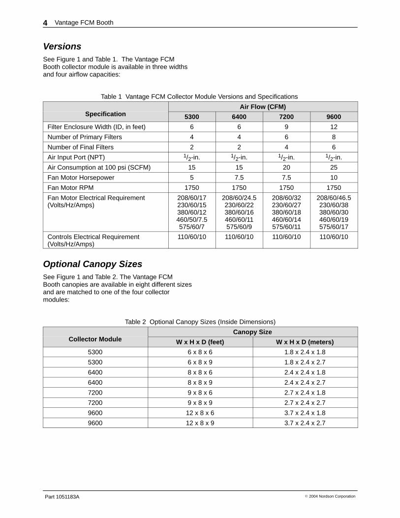
Versions See Figure 1 and Table 1. The Vantage FCMBooth collector module is available in three widthsand four airflow capacities:
Table 1 Vantage FCM Collector Module Versions and Specifications
S ifi iAir Flow (CFM)
Specification 5300 6400 7200 9600
Filter Enclosure Width (ID, in feet) 6 6 9 12
Number of Primary Filters 4 4 6 8
Number of Final Filters 2 2 4 6
Air Input Port (NPT) 1/2-in. 1/2-in. 1/2-in. 1/2-in.
Air Consumption at 100 psi (SCFM) 15 15 20 25
Fan Motor Horsepower 5 7.5 7.5 10
Fan Motor RPM 1750 1750 1750 1750
Fan Motor Electrical Requirement(Volts/Hz/Amps)
208/60/17230/60/15380/60/12460/50/7.5575/60/7
208/60/24.5230/60/22380/60/16460/60/11575/60/9
208/60/32230/60/27380/60/18460/60/14575/60/11
208/60/46.5230/60/38380/60/30460/60/19575/60/17
Controls Electrical Requirement(Volts/Hz/Amps)
110/60/10 110/60/10 110/60/10 110/60/10
Optional Canopy Sizes See Figure 1 and Table 2. The Vantage FCMBooth canopies are available in eight different sizesand are matched to one of the four collectormodules:
Table 2 Optional Canopy Sizes (Inside Dimensions)
C ll M d lCanopy Size
Collector Module W x H x D (feet) W x H x D (meters)
5300 6 x 8 x 6 1.8 x 2.4 x 1.8
5300 6 x 8 x 9 1.8 x 2.4 x 2.7
6400 8 x 8 x 6 2.4 x 2.4 x 1.8
6400 8 x 8 x 9 2.4 x 2.4 x 2.7
7200 9 x 8 x 6 2.7 x 2.4 x 1.8
7200 9 x 8 x 9 2.7 x 2.4 x 2.7
9600 12 x 8 x 6 3.7 x 2.4 x 1.8
9600 12 x 8 x 9 3.7 x 2.4 x 2.7

Vantage FCM Booth 5
Part 1051183A� 2004 Nordson Corporation
Installation
WARNING: Allow only qualified personnelto perform the following tasks. Follow thesafety instructions in this document and allother related documentation.
Delivery Perform the following tasks when the booth isdelivered.
� Take inventory of all equipment. Make sure thatyou have all of the materials listed on thepacking slip.
� Inspect each component for damage.Document any damage that you find and reportit to both the carrier and your Nordsonrepresentative.
� Clear the area of all obstructions.
� Provide a secured, indoor storage area forequipment.
� Clear the route from the delivery site to theinstallation site. Make sure that there issufficient clearance for all equipment.
Preparation Perform the following tasks before installing thebooth.
� Obtain any necessary local or state permits.
NOTE: Compliance with local, state, andnational codes including NFPA Bulletin 33 andbuyer’s insurance is the responsibility of thebuyer.
� Make sure that the installation area has a level,class-B floor.
� Make any building alterations to meet local,state, and national codes in the powder coatingroom.
� Install sprinkler heads as required by yourinsurance carrier or local, state, and nationalcodes.
� Make sure that you have sufficient electricalservice and compressed air available for bothinstallation and operation at the installation site.
� Locate the booth in a proper environment. Iftemperature and humidity in the spray roomexceed the following ranges, you should installair conditioning equipment.
Temperature 21-27 �C (70-80 �F)Humidity 45-55% RH
� If applicable, install the conveyor. Theconveyor and its hangers must be built andtested at the site before the booth isassembled.
� Provide trash bins and off-site disposal forrefuse, skids, and crating.
Clearances The installation area should have ample floor spacefor coating operations and service. There must beat least 1-m (3-ft) clearance between the final filtersand any wall, roof, or other object to allow free airflow.
Mechanical Assembly 1. See Figure 2. Mark out the booth position on
the floor.
2. Lay the 2-in. floor channel (6-, 9-, or 12-ft long)along the position of the back wall of the filterenclosure.
3. Assemble the filter enclosure side panels(42-in. wide, 14 gauge, with stiffeners) and backpanels (36-in. wide, 18 gauge) with 5/16-in. nutsand bolts. Hand-tighten the fasteners.
4. Make sure the panels are straight, that the sidepanels are square with the back panels, andthat the enclosure is sitting solidly on the floor inthe correct position. Use shims if necessary.
5. Tighten the panel fasteners, then lag theenclosure to the floor to provide a stable basefor the fan module.
6. Using an appropriate lifting device, carefullyraise the fan module onto the filter enclosure.Attach the module to the enclosure with 5/16-in.nuts and bolts and tighten them securely. Donot remove the lifting device until assembly iscomplete.
7. See Figure 3. Mount the control panel, pilotvalve assembly, and regulator on theappropriate side of the enclosure.

Vantage FCM Booth6
Part 1051183A � 2004 Nordson Corporation
Mechanical Assembly (contd)
8. See Figure 7. Install the cartridge filter rodsand filters as described in Cartridge FilterInstallation. Attach the retainers to the bottomof the filters.
9. Attach canopy panels to the filter enclosure.Refer to Figures 4, 5, and 6 for canopymounting hole patterns.
1401390A
Fan Module
Side Panels(14 Gauge)
Back Panels(18 Gauge)
2 in. Floor Channel
5/16-in.nuts and bolts
5/16-in.nuts and bolts
Lag panelsto floor
Figure 2 Booth Assembly

Vantage FCM Booth 7
Part 1051183A� 2004 Nordson Corporation
FILTER/REGULATOR
PILOT VALVE ASSEMBLY
CONTROL PANELWIRING TOFAN MOTOR
1401391A
Figure 3 Control Panel, Pilot Valve Assembly, and Filter/Regulator Installation (Left-Hand Orientation Shown)
Vantage FCM Booth8
Part 1051183A � 2004 Nordson Corporation
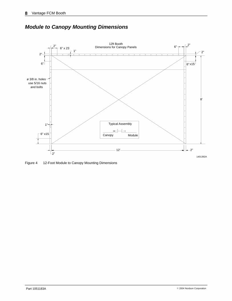
Module to Canopy Mounting Dimensions
1401392A
12ft BoothDimensions for Canopy Panels
12’
6” x15
2”
1”
2”
6”
2”6” x 23
1”
8’
2”
6” x15
2”
2”6”
ø 3/8 in. holesuse 5/16 nuts and bolts
ModuleCanopy
Typical Assembly
Figure 4 12-Foot Module to Canopy Mounting Dimensions

Vantage FCM Booth 9
Part 1051183A� 2004 Nordson Corporation
1401393A
9’
6” x15
6”
2”
2”
1”
1”6” x17
2” 6”2”
6”x15
2”
8’
2”
9ft BoothDimensions for Canopy Panels
ø 3/8” holesuse 5/16 nuts and bolts
Canopy Module
Typical Assembly
Figure 5 9-Foot Module to Canopy Mounting Dimensions

Vantage FCM Booth10
Part 1051183A � 2004 Nordson Corporation
1401393A
8’
6’
1”
6” x15
2”
2”
6”
2”
1”
6” x112”
6ft BoothDimensions for Canopy Panels 2”
6”x15
6”2”
ø 3/8” holesuse 5/16 nuts
and bolts
Canopy Module
Typical Assembly
Figure 6 6-Foot Module to Canopy Mounting Dimensions
Cartridge Filter Installation
See Figure 7.
1. Install the filter rods (3) through the spigot andsecure them with the flanged nuts (1), so thatthe end of the rod is flush with the top of theupper nut.
2. Install the cartridge filters (4) on the rods, openend first. Align the filter so the end of the filterrod slides through the mounting hole in theclosed end of the filter.

Vantage FCM Booth 11
Part 1051183A� 2004 Nordson Corporation
3. Secure the filter with the 3/8-in. washer (2) andflanged nuts (1). Tighten the nuts to compressthe filter gaskets at the open ends. Do notovertighten the nuts or you may damage thefilter.
4. Once all filters are installed, install the filterretainer strip(s) (5) over the ends of the filterrods and install the 3/8-in. wing nuts (6).
1401394A
1
1
3
4
2
1
5
6
END OF RODFLUSH WITHTOP OF NUT
Figure 7 Cartridge Filter Installation1. 3/8-in. flanged nuts2. 3/8-in. washer
3. Filter rods4. Cartridge filters (48 in.)
5. Filter retainer strip(s)6. 3/8-in. wing nuts
Compressed Air Connection
Compressed air requirements:
Pressure: 4-7 bar (60-100 psi)
Air Quality: Air must be clean and dry. Adedicated, refrigerated or regenerative-desiccantair dryer that can produce a 3 �C (38 �F) or lowerdewpoint at 7 bar (100 psi) is recommended.
Install a shutoff valve and drop leg with drain valveahead of the filter/regulator.
See Figure 3. Connect the compressed air supplyto the filter/regulator.

Vantage FCM Booth12
Part 1051183A � 2004 Nordson Corporation
Electrical Connections
WARNING: All phases of installation mustcomply with all federal, state, and localcodes. All work that is located in Class 2,Divisions 1 and 2 hazardous locations mustcomply with NFPA code 33, and NFPAcode 70 (especially articles 500, 502, and516, latest editions).
The booth requires both 3 phase power for the fanmotor at the voltage specified in the purchaseorder, and 120 volt single phase power for theother booth devices and controls.
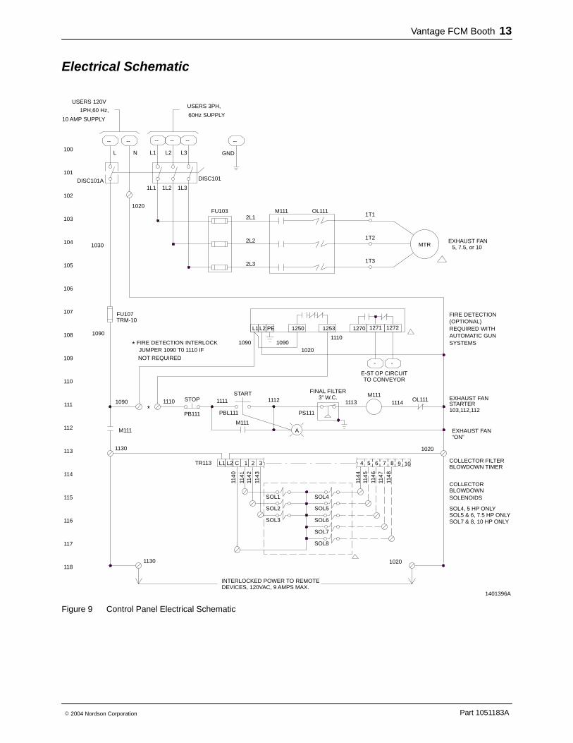
Use Figure 9 to make your electrical connections.
� Install a fused, locking disconnect switch, wiredin accordance with National Electric CodeNFPA-70, in the main electrical line supplyingpower to the control panel. You must be able todisconnect and lock out power to the boothcontrol panel.
� Use dust-tight strain reliefs or conduitconnectors to bring power into the the boothcontrol panel.
� As required, connect the pre-wired motorconduit to the control panel and/or motorjunction box. Connect the conduit wiring to thecontrol panel or motor leads. If necessary, referto the wiring diagram on the motor junction box.
NOTE: The fan motor must rotate in the correctdirection to draw air through the cartridge filters. Tochange fan direction, reverse any two motor wiresat the motor starter in the control panel.
� As required, connect the pre-wired pilot valveconduit to the control panel and/or pilot valveassembly.
Pulse Valve Timer Settings
See Figure 8. Locate the sequential timer board onthe inside door of the electrical panel.
PULSE DURATION (ON TIME): Time pulse valvesare open. Factory set to 0.1 second. Normally, thissetting does not have to be changed.
PULSE FREQUENCY (OFF TIME): Time betweenpulses. Set as desired. This setting is dependenton the volume of powder being sprayed and thestatic pressure reading on the cartridge filters. Alower setting results in more frequent pulsing andhigher air consumption.
1401395A
0
50
75
100125
150
180 0
.1
.3
.5
.4
OFF TIME ON TIME
.2
Figure 8 Pulse Valve Timer Settings
Vantage FCM Booth 13
Part 1051183A� 2004 Nordson Corporation
Electrical Schematic
1401396A
103,112,112
SOL2
SOL3
SOL1115
114
113
112
1130
1130
M111
INTERLOCKED POWER TO REMOTEDEVICES, 120VAC, 9 AMPS MAX.
PB111
M111
PBL111
321CL2L1TR113
1140
PS111
A
BLOWDOWN TIMERCOLLECTOR FILTER
1020
BLOWDOWNSOLENOIDS
COLLECTOR
1110
FINAL FILTER
102
1110
NOT REQUIREDJUMPER 1090 T0 1110 IF
FIRE DETECTION INTERLOCK
1090
109
111
110
108
107
1090
FU107
1030
106
105
104
103
1020
STOPSTART
1111
1090
L1
1112 3” W.C.
1250
1090
PEL2
1020
1253
2L3
FU103
2L2
2L1M111 OL111
--
1PH,60 Hz,
10 AMP SUPPLY
DISC101A
100
101
L
1L1 1L2
L1N L2
-- -- --
DISC101
1L3
L3 GND
60Hz SUPPLY
-- --
FIRE DETECTION
OL111
E-ST OP CIRCUITTO CONVEYOR
1113M111
-
1114
-
1270 1271 1272
EXHAUST FANSTARTER
REQUIRED WITH(OPTIONAL)
SYSTEMSAUTOMATIC GUN
MTR
1T3
1T2
1T1
EXHAUST FAN5, 7.5, or 10
USERS 120VUSERS 3PH,
118
117
116
1020
4 5 6
SOL5
SOL4
1141
1142
1143
1144
1145
SOL6
1146
SOL5 & 6, 7.5 HP ONLY
TRM-10
SOL7
SOL8
7 8
1147
1148
9 10
SOL7 & 8, 10 HP ONLY
SOL4, 5 HP ONLY
*
*
EXHAUST FAN“ON”
Figure 9 Control Panel Electrical Schematic
Vantage FCM Booth14
Part 1051183A � 2004 Nordson Corporation
Operation WARNING: Allow only qualified personnelto perform the following tasks. Follow thesafety instructions in this document and allother related documentation.
Startup 1. Turn on the compressed air supply. Adjust the
system air pressure to 5.5 bar (80 psi).
2. Turn on the control panel disconnect switch.
3. Turn on the exhaust fan by pressing the FANSTART (1) button.
4. Set the pulse-valve air pressure to 1.7 bar(25 psi). Adjust as required to efficiently cleanthe cartridge filters.
5. Check the cartridge filter differential pressuregauge on the control panel. The pressureshould be less than 4.0-in. w.c. If it is higher,increase the filter pulsing frequency or airpressure.
NOTE: The final filter pressure switch will shutdown the exhaust fan is the final filter differentialpressure reaches 3.0 in. w.c. If this happens, thefinal filters are clogging. Refer to Troubleshootingto correct this problem.
6. Check the level of the powder in the feedhopper. Fill feed hoppers no more than 2/3 fullto leave room for expansion when fluidizing airis turned on.
7. Turn on the feed hopper fluidizing air.
8. Check all equipment ground connections.
9. During production, make sure the sprayedpowder is not escaping from the booth. If thishappens, check the cartridge filter differentialpressure. Increase pulsing frequency orpressure.
Shutdown 1. Blow the powder off the canopy walls.
2. Vacuum the waste powder off the floor.
3. Clean your powder application equipment.
4. Shut off the exhaust fan.
5. Turn off the control panel disconnect switch.

Vantage FCM Booth 15
Part 1051183A� 2004 Nordson Corporation
Troubleshooting WARNING: Allow only qualified personnel to perform the following tasks. Follow the safetyinstructions in this document and all other related documentation.
This section contains troubleshooting procedures. These procedures cover only the most common problemsthat you may encounter. If you cannot solve the problem with the information given here, contact your localNordson representative for help.
Problem Possible Cause Corrective Action
1. Powder escapingfrom booth openings
Cartridge filters clogged because
� Inadequate pulse pressure Increase the pulse air pressure.
� Pulse off timing too long Decrease the pulse off time.
� Powder too fine orcontaminated
If using reclaimed powder, reduce theratio of reclaimed-to-virgin powder.Check powder particle size, ifnecessary.
� Powder contaminated Replace the contaminated powder.
� Pulse valve or solenoid valvemalfunction
Isolate the problem component andrepair as follows:
� The pulse valve diaphragm isruptured. If you hear a hissingsound inside the fan housing,check for constant air flow fromthe valve. Rebuild or replace thedamaged valve.
� The pulse valve spring is broken,or the solenoid valve is nottriggering the pulse valve. If acartridge filter is not being pulsed,check the valve pilot air tubingand solenoid wiring; correct ifdisconnected or failed. Check thecontinuity across the solenoidterminal (with power off andlocked out). If it is shorted open,replace the solenoid. If thesolenoid valve is good, replacethe pulse valve.
Cross drafts Check for cross drafts across thebooth openings and correct asnecessary.
Parts entering booth are too hot Cool the parts to 48 �C (120 �F) orbelow before bringing them into thebooth.
Continued...

Vantage FCM Booth16
Part 1051183A � 2004 Nordson Corporation
Corrective ActionPossible CauseProblem
1. Powder escapingfrom booth openings(contd)
Powder flow exceeds ability ofexhaust fans to contain
Reduce the powder flow or thenumber of guns.
Booth openings exceed designcriteria
Close off or decrease the size of theopening.
Parts too large, interrupting flow ofair through booth
Contact your Nordson representative.
Exhaust fan rotation reversed Reverse the rotation of the motor byswitching the wiring.
2. Exhaust fan shutsdown, will not restart
Final filters are clogged Check final filter differential pressuregauge. If over 3-in. w.c., checkcartridge filter media and gaskets fordamage. Replace damaged filters.
Fuse(s) blown Check for the reason the fuse(s) blewand correct it. Replace the blownfuse(s).
Fan motor overload shutdown Correct one of the following possiblemotor, contactor, fuse or operationalproblems as needed:
� Check the exhaust fan for properrotation direction.
� Check for mechanical binding ofthe motor/fan assembly.
� Check for contact corrosion at themotor starter in the control panel.
� Check the overload protector inthe control panel.
3. Cartridge pulsing willnot start
No air supply to pulse manifolds Check the air supply.
Solenoid shorted; blows timerboard fuse
Call an electrician.
Timer board malfunction or otherelectrical problem
Call an electrician.

Vantage FCM Booth 17
Part 1051183A� 2004 Nordson Corporation
Parts To order parts, call the Nordson Finishing Customer Support Center at (800) 433-9319 or your localNordson representative.
Replacement Parts Part Description Note
1014960 Reverse pulse valve1042591 Cartridge filter, 48 in.1042595 Filter rod1032826 Final filter (35.5 x 20.5 x 5.5) A1066540 Final filter (35.5 x 23.5 x 11.5) A1042596 Final filter (35.5 x 20.5 x 8.5) A1042655 Inlet cone (5300 CFM, 5 HP motor)1042656 Inlet cone (6400/7200 CFM, 7.5 HP motor)1014952 Inlet cone (9600 CFM, 10 HP motor)1042653 Fan wheel (5300 CFM, 5 HP motor)1042654 Fan wheel (6400/7200 CFM, 7.5 HP motor)1014950 Fan wheel, (9600 CFM, 10 HP motor)1042592 Pulse valve assembly (4 valves)1042593 Pulse valve assembly (6 valves)1042594 Pulse valve assembly (8 valves)
NOTE A: Measure your existing final filters before ordering replacements.
Final Filters by Model Booth Model Final Filter P/N Filter Size (LxWxD) Quantity per Booth
VTG-5300c 1032826 35.5 x 20.5 x 5.5 2
VTG-6400c 1032826 35.5 x 20.5 x 5.5 2
VTG-7200c 1066540 35.5 x 23.5 x 11.5 3
VTG-8500c 1066540 35.5 x 23.5 x 11.5 3
VTG-9600c 1066540 35.5 x 23.5 x 11.5 4
VTG-10600c 1032826 35.5 x 20.5 x 5.5 4
VTG-12800c 1032826 35.5 x 20.5 x 5.5 4
NOTE: Some older batch booths used 1042596 (35.5 x 20.5 x 8.5) filters. Always measure your filters beforeordering replacements.
Fan Motors
HP 208V 230/460V 380V 575V5 1043155 1043155 - 1043156
7.5 1043157 1043157 - 1043158
10 1022543 1014957 1022544 1014958

Vantage FCM Booth18
Part 1051183A � 2004 Nordson Corporation
Control Panel Parts See Figure 10.
SIZE
5 HP
7.5 HP
FU103 AJT 25
FLA
M111
FU103
M111
24.2
AJT 45
FLA
ITEM 208V
15
AJT 25
AJT 40
22
EXHAUSTER REF. CHART
230V
15.2
AJT 12AJT 15
11
AJT 20
8.2
AJT 15
7.6
460V
6.1
575V
OL111
OL111
TOTAL SYSTEM CURRENT
DISCONNECT (DISC101) REF. CHART
DISCONNECT
0.0A - 34.0A
51.1A - 86.9A
34.1A - 51.0A OT63E3
OT100E3
OT45E3
FU103
FU103
6J60A3B 6J30A3B6J30A3B
6J100A3B 6J100A3B 6J30A3B6J60A3B
10 HP
FLA
M111
FU103
OL111
FU103
AJT 60
A40-30-10-84
32.2
A16-30-10-84
AJT 50
A30-30-10-84
28
AJT 20AJT 25
A12-30-10-84
14 11
6J60A3B 6J60A3B 6J30A3B6J30A3B
A16-30-10-84TA25DU19
6J30A3B
A9-30-10-84TA25DU11
TA25DU14TA25DU19TA25DU32TA42DU42
A12-30-10-84TA25DU14
A26-30-10-84A26-30-10-84TA25DU25TA25DU25
A16-30-10-84TA25DU19
A9-30-10-84TA25DU8.5
A9-30-10-84TA25DU6.5
DISC101
1
1 DISCONNECT, NON-FUSED
SUB-P ANEL
ABB
M111
FU107
1
1
PBL111 1
1
TR113 1
ZB4 BW353
SEE CHARTCONTACTOR, MOTOR
FUSEBLOCK
PUSHBUTTON HEAD, ILLUM., AMBER, L.E.D.
GOULD
ALLEN BRADLEY
TELEMECANIQUE
-----NAMEPLATE, WHITE
TIMER BOARD
1 SMCBREATHER VENT
BULKHEAD UNION, 6MM
PRESSURE SWITCH
MALE CONNECTOR, 6MM x 1/8NPT KQ2H06-01S
KQ2E06-00
1910-5
AN203-KMB
SMC
SMC
DWYERPS111 1
ITEM QTY DESCRIPTION PART NO. MFG.
SEE CHART
1 ENCLOSURE
USM1
1
2PS111,GA5,GA10
PS111
ATM1
FU107 1 FUSE, CONTROL GOULDTRM10
FU103 3 FUSE,J TYPE, TIME DELAY GOULDSEE CHART
OL111 1 OVERLOAD,MOTOR SEE CHART
DISC101
DISC101
1
1
DISCONNECT, HANDLE
DISCONNECT, EXTENDED SHAFT
ABB
ABB
OXZS49
OHB80J6
ALLEN BRADLEY
PBL111 1 PUSHBUTTON, BASE ZB4 BZ009 TELEMECANIQUE
1 PUSHBUTTON, HEAD,RED ZB4BA9 TELEMECANIQUE
1 PUSHBUTTON, BASE ZB4BZ102 TELEMECANIQUE
DWYER2-5005MINIHELIC GAGE 0-5 IN. W.C.1GA5
GA3 1 MINIHELIC GAGE 0-3 IN. W.C. 2-5003 DWYER
PS111,GA5 1 PLUG-IN ”Y”, 6MM KQ2U06-99 SMC
DNC-T2006-B10 NCC
DISC101A
M111 1 CONTACT, AUXILLIARY 100-SA10 ALLEN BRADLEY
PB111
PB111
FU103 1 FUSEBLOCK MARATHONSEE CHART
TUBING, 6MMA/RPS111,GA5,GA10
1 AUX. CONTACT, DISCONNECT ABBOA1G10
3 COVER, HOLE A-SPBG HOFFMAN
A/R DIN RAIL 199DR1TB,FU107,OPTIONS
25 TERMINALS 57.504.0055.6 WEILANDTB
PBL111 1 LIGHT MODULE, LED, AMBER,120V ZBVG5 TELEMECANIQUE
PBL111 1 CONTACT BLOCK, NO ZBE101 TELEMECANIQUE
ALLEN BRADLEY
PB111 1 CONTACT BLOCK, NC ZBE102 TELEMECANIQUE
TR113 1 TIMER BOARD (9600 CFM BOOTH ONLY) DNC-T2010-B10 NCC

Vantage FCM Booth 19
Part 1051183A� 2004 Nordson Corporation
10 AMP MAXIMUM
1401397A
M111
OL111
PS111
FU103
DISC101
TRM-10 OR EQUAL
FU107
DISC101A
TB
GROUND
GROUND LUG
100-C60
193-EA
LUG
PNEUMATIC SCHEMATIC
GA3
0 3
0 5
TR113
PBL111
FAN STOP
PB111
FAN START
A
PRIMARY FILTERS
FINAL FILTERS
GA5
Figure 10 Control Panel Parts

Vantage FCM Booth20
Part 1051183A � 2004 Nordson Corporation