vanguard - peter mcleland · 1 vickers vanguard 951/953 cockpit manual version 5.0 january 2008 for...
TRANSCRIPT

1
VICKERS
VANGUARD
951/953
Cockpit Manual
Version 5.0 January 2008
For use with Rick Piper’s Vickers Vanguard for Flight Simulator 2004
by Fraser A. McKay
Sound set by Fraser McKay Autopilot refinements by David Maltby
Photography by David Booker Technical advice by Robbie Arnold
Internal sounds xml source courtesy Doug Dawson.

2
VC9 V5 CONTENTS
MUST READ 1. ELECTRICAL SYSTEM 2. ENGINE & PROPELLER CONTROLS 3. FUEL SYSTEM 4. FLYING CONTROLS, FLAPS & UNDERCARRIAGE 5. DEICING SYSTEMS 6. AIR CONDITIONING 7. RADIO INSTALLATION & AUTOPILOT 8. MINOR SYSTEMS
9. LIMITATIONS 10. ENGINE & FLIGHT HANDLING
MUST READ It is essential that new users familiarise themselves with the contents of the manual to avoid getting into difficulty. Those who are familiar with the previous version are also advised to do so. While I am happy to resolve queries by email or through the cbfsim forum, please read the manual first. I will no longer be supporting previous versions of this panel. Note that engine speed is controlled entirely by the throttle lever therefore joystick and keyboard commands for propeller and mixture control are not necessary. VC9 V5

3
1.ELECTRICAL SYSTEM 28V DC Supplies The controls for the aircraft’s electrical system are located on the Overhead Rear panel, which also houses the switches for the lights, windscreen heat and notices. The electrical system is more complex that that the Viscount, and the casual user can get away with leaving it alone, as long as the Alternators are left on and the two main Inverter switches are set to 1 and 2 respectively. An Alternator driven by each engine provides AC power which through Transformer Rectifier Units (TRUs) supply the main 28VDC electrical system. An additional alternator mounted on engines 1 and 4 supply the deicing system. Failure of Nos 1, 2 or 4 alternators will trip a demand for a changeover to another alternator, and illumination of the appropriate Alternator Changeover Lamp, at which time the Changeover Switch should be operated.

4
115V AC Supplies 115VAC for the instrumentation and autopilot is provided by two 3 kVA inverters. They are normally set to 1 and 2, the 3 position selects a third inverter should another fail. The inverters supply the following systems:
SFS Director Horizon VHF Com1 and 2 RMIs & Beam compass VOR/ADF Note that these systems Fuel Quantity Gauges Transponder are inoperative with the
Servo Altimeter Markers inverter switch OFF Oil Gauges Cockpit Lighting Autopilot PUD Cyclic Timer
A 450 VA inverter is provided for emergency use and is powered by the aircraft batteries, and is intended for use if a total TRU failure occurs. This inverter only replaces the services supplied by No1 inverter. Emergency Power Clicking on the area of the Red Emergency Power arrow will operate the gangbar, and set the switching to the emergency position. Services lost are: SFS Director Horizon SFS Beam Compass VOR/ILS Autopilot Markers Anti Icing Nav Lights Brake Pressure Gauges Landing Lights CDI AP Engage & Trim Moving the External Power Master to on overrides the batteries and allows the aircraft to be powered externally, and the battery isolate warning lamp will light. Moving the Internal Master to off when this is done prevents the aircraft reverting to battery power if the GPU drops off line. (Simulated only)
VC9 V5

5
2. ENGINE & PROPELLER CONTROLS Throttles and HP Cocks Each engine drives a four bladed constant speed fully feathering propeller of 14’ 6” diameter. Fuel flow and propeller RPM are selected through a single lever referred to as the throttle. Movement of each lever will automatically select propeller RPM for that throttle position as well as the required fuel for that RPM. Keyboard or joystick propeller commands will be ineffective and should be avoided. The throttle quadrant can be opened with the icon. When the flying controls are locked, the throttles are restricted to movement in the ground Beta range only. This allows sufficient power for taxying but not for takeoff. There are mouse areas and tooltips in each lever slot to move the levers, however it is more convenient to use the engine selector in conjunction with the joystick or keyboard controls. Clicking on any single number will select that particular engine, or between them the inboards or outboards or left or right engines.
To the right of the throttles are the four High Pressure (HP) Fuel Cock Levers. The HP Cocks control the flow of fuel directly to the engine. They operate differently than those on the Viscount. Each lever has several positions, and is operated by clicking in the appropriate area. The areas have been highlighted in the illustration for clarity. The white area selects the Feathering position, which must be selected before operating the feathering handle. Fuel is shut off in this position. The red area selects the Shut position, and the engines are normally closed down by moving the lever to Shut and closing the fuel supply. The blue area moves the lever to the initial open position, introducing fuel to the engine. The green area at the forward end moves the lever to the fully open (rich) position. The yellow area between the open and fully open positions is the Fuel Trimming range. To prevent the engines overheating on takeoff or go around the fuel must be trimmed in accordance with the Fuel Trim Chart. This reduces the fuel flow without alteration to RPM by altering the interconnected throttle and propeller controls. Clicking, or scrolling the mouse wheel, in the rearward end of the yellow area gradually reduces the fuel trim setting, and in the forward end will gradually increase it. The Tooltip shows the accurate setting. Once climb power has been set, the levers may be returned to the 100% setting or less if conditions dictate. For convenience, all engines may be trimmed simultaneously by clicking on the small rectangular area between Nos2 and 3 levers at the top of the scale.
The fuel mixture is preselected through the HP cock levers, therefore mixture controls on joysticks should be left at the fully rich or fully weak positions and movement avoided.

6
VC9 V5 Propellers The propellers have a number of mechanical and hydraulic safety devices, the two main systems are represented for FS purposes. The mechanical Flight Fine Pitch stop is always in position in the air to prevent the propeller blades returning to ground fine pitch during flight. The stop is retracted when the throttles are retarded below flight idle, when the propellers are free to fine off below the pitch stop. In order that the throttles may be retarded below flight idle, and to prevent inadvertent stop withdrawal in the air, the propeller Ground Lever, located between the throttles and HP cocks, must be moved to the Ground position. This simultaneously lifts a plate behind the throttle levers and allows further rearward movement toward ground idle and reverse. This action would be required to be performed manually, however, for convenience the lever will jump to the Ground position on landing with the weight on the wheels and throttles closed. Similarly when the throttles are advanced immediately prior to takeoff to the 10500 RPM position, the lever will move to the Flight position and the plate will drop behind the throttle levers preventing a return to the ground range during flight. A double filament lamp in the centre of the instrument panel will light when the Ground Lever is in the Ground position. There are adjacent amber Prop Below Flight Fine lamps, one for each propeller, which light when the associated propeller moved below the Flight Fine Pitch stop.
Additionally, the Auto Drag Limiting system prevents the propeller from assuming too fine a pitch in the event of power loss. The system senses shaft torque under varying engine power settings, so if torque falls below the datum level propeller pitch is automatically coarsened. Four red Auto Drag Limit lamps, one for each propeller, in the centre instrument panel light when the system is operating. In the event of engine failure, pitch is coarsened until the propeller is almost feathered. The system does not operate in the ground range. Feathering Before feathering can take place the appropriate HP cock lever must be placed in the fully rearward Feathering position. The Fire Handle on the coaming is then pulled, at which time the light will come on while the feather pump is operating, then extinguish when feathering is complete. The tooltip shows TO FEATHER if the prop is unfeathered and TO UNFEATHER if it is feathered. If the light does not go out unfeather and then refeather. Unfeathering is possible irrespective of HP cock lever position.
Starting Controls

7
The starting procedure on the Vanguard is different to that on most turboprop aircraft of its generation, and is difficult to replicate accurately in Flight Simulator. However this has been accomplished accurately from a cockpit point of view, however externally the propellers will not be seen to move until the final stages of startup. In order to keep engine temperatures at an acceptable level during start, fuel is introduced gradually during the start cycle. The starting system cannot be commenced until the HP cocks have been shut and the four Start Fuel levers, forward of the throttle levers, have been set to the start position. When the Start Fuel levers are at start the throttles are prevented from advancing beyond the Ground Idle position. Four Start Fuel magnetic indicators in the centre overhead panel should be checked to show START when the levers are placed in the Start position. Flaps must be UP before commencing a ground start. The starting controls are located on the right of the overhead systems panel which can be viewed with the icon. The controls for normal ground starting consist of a starter master switch, four starter/relight switches and start cycle and ignition warning lamps. For a normal start the master should be selected to START and the No3 start switch momentarily held in the Start position. The Start Cycle and Ignition lights will come on. After approximately 10 seconds or 500 LP RPM, the No3 HP cock should be moved to the Open position, introducing fuel into the engine. The LP RPM will continue to rise to approximately 2200 and the TGT will rise then fall to stabilise at around 450’C. Oil pressure should be checked rising and the waning lamp out. At the end of the start cycle the Cycle and Ignition warning lamps will go out. The engine is now running at Low Ground Idle. The remaining engines are started in the same way, normally 4,1,2. Once all the engines are running at Low Ground Idle, the Nos 3 and 4 Start Fuel levers can be moved to OFF. This starts slow moving actuators which gradually increase the fuel flow until the engine is running at High Ground Idle, 11200-11600 LP RPM. During this process the Start Fuel magnetic indicators will change from START to cross-hatch, then finally to NORM when the operation is complete. The HP Cocks can then be set to the trim position for takeoff. Repeat for engines 1 and 2. Return the Start Master switch to OFF. To feather a propeller manually the appropriate HP cock must be set to feather then the feathering button pressed. The red lamp confirms the propeller is feathered. In reality the lamp would only glow while the feather pumps were working, however we don’t have the luxury of looking out the window to check the blades visually. Unfeathering is accomplish-ed by pressing the button again until the lamp remains out. (See Engine & Flight Handling) For engine air relights, the start switch should be selected to relight. Instrumentation The centre instrument panel houses the instruments relevant to the engines and each has an engine LP RPM indicator, a dual pointer torquemeter, a turbine gas temperature indicator a combined oil pressure and temperature indicator. Additionally there are four fuel flowmeters calibrated in kg/hr, incorporating a kgs consumed counter which can be reset using the knob to the bottom right of the instrument. This is a direct division of the total fuel used therefore is not accurate for any particular engine.To the right of the engine instruments is a propeller synchroscope. VC9 V5

8
3. FUEL SYSTEM Fuel is carried in four integral tanks, an outboard and inboard tank on each side, numbered 1-4 corresponding to the engines. The useable tank capacities are: No1 Tank (Left Tip) 680 imperial gallons – 816 U.S. gallons – 2472 kg
No2 Tank (Left Aux) 1885 imperial gallons – 2262 U.S. gallons – 6854 kg No3 Tank (Right Aux) 1885 imperial gallons – 2262 U.S. gallons – 6854 kg
No4 Tank (Right Tip) 680 imperial gallons – 816 U.S. gallons – 2472 kg
Fuel Contents There are four contents gauges, one per tank, on the starboard sill panel, made visible with the icon. The instrument faces are calibrated in kg . Fuel Controls Fuel controls are grouped on the overhead centre panel opened with the icon.

9
The fuel systems on the port and starboard sides of the aircraft are identical and are connected by a crossfeed pipe. A Crossfeed cock and Inter Engine cocks enable fuel to be drawn from any tank or combination of tanks. The Inter Engine and Crossfeed cocks are operated by three switches at the forward end of the fuel panel, and each cock has an associated position indicator. The outboard tanks can be isolated using the Tank1 and Tank 4 Isolate switches, which also have magnetic indicators showing NORM/ISOL. In each tank there are duplicated booster pumps which raise the pressure of the fuel prior to delivery to the engine. These are controlled by switches on the overhead panel, one for each pump, forward and aft. Above the switches are four red booster pump fuel pressure warning lamps. Both pumps in each tank should normally be switched on for start, taxy and takeoff approach and landing, and should be switched off after shut down, when the pressure warning lamps will light. The Low Pressure fuel cocks are controlled by four single throw switches and have associated position indicators. There are four fuel temperature indicators at the rear of the panel and NORM/DECREASE switches adjacent to them. The switches are left at NORM on the ground at OATs of up to 25’C, and set to DECREASE at higher ambient temperatures. The switches are returned to norm as soon as practicable after takeoff. Fuel Management Fuel should be loaded equally between the four tanks until the outers are full, at which time any balance should be loaded into the inner tanks. After takeoff, if fuel is greater in the inner tanks, open the inter engine cocks and switch off the booster pumps in the outer tanks. Fuel will now be supplied to the port engines from No2 tank and the starboard engines from No3. When the contents of the inner tanks runs down to match the levels in the outers, switch on all of the booster pumps again and close the inter engine cocks. Each tank will now feed its respective engine. Take care to make the selections in the correct order to avoid fuel starvation.
VC9 V5
10
4. FLYING CONTROLS , FLAPS & UNDERCARRIAGE Trim Controls The Vanguard has conventional manually operated controls operating through spring tabs for the elevator, ailerons and rudder. Mouse areas on the Autopilot Trim indicator can be clicked to vary the trim settings. Gust Locks
The flying controls are fitted with internal gust locks, which should be engaged at the en of the landing run and released immediately prior to take off. The control lever is on the side of the quadrant and the locks are in by default restricting the throttles to the ground range. For FS purposes the gust locks will only lock the elevator and ailerons so as to leave the rudder free for steering on the ground. Flaps The flaps are hydraulically operated and are controlled by a lever on the pedestal and
have five settings. A positive lock prevents retraction above the takeoff position, before that position has been reached during retraction, to prevent inadvertent over retraction during an overshoot. An amber 5’ Flap Over-Speed warning lamp lights when the airspeed exceeds 210kt in this configuration. 0’ Fully retracted. 5’ Climb setting. 20’ Takeoff setting 30’ Approach setting 40’ Landing setting. The flap position indicator is in the top left of the centre instrument panel. The normal flap
selector is on the pedestal. An emergency switch can be used to raise or lower the flaps once the Emergency Flap switch is selected on. Maximum speed for flap Climb as Vno Maximum speed for flap Take Off 200kt IAS Maximum speed for flap Approach or Land 162kt IAS
Flap should be selected to Climb for normal en route climb, and retracted at 200kt.
Undercarriage The Undercarriage Selector consists of a lever on the quadrant marked CHASSIS UP
and DOWN. A standard RAF type undercarriage position indicator is fitted to the left main instrument panel and shows; Green lights : Undercarriage locked down Red lights: Undercarriage unlocked or in transit. No lights: Undercarriage locked up

11
Additionally the nose red lamp will glow of the flap lever is selected beyond the 20’ position and any undercarriage leg is not locked down, FS also provides us with an aural warning if the flaps are extended beyond 20’ before undercarriage extension. Clicking the centre of the indicator substitutes alternative filaments.
Maximum speed for extension 200kt IAS Maximum speed for retraction 180kt IAS
A tiller for steering the nosewheel is at the left side if the main panel, viewed with the icon, and can be steered left or right by clicking on the appropriate side or with the mouse wheel. An area immediately above the hub may be clicked to centre the nosewheel. 5. DEICING SYSTEMS Pitot Heaters Two switches on the overhead left panel control the electrical supply to the pitot heaters, and two dolls-eye magnetic indicators are fitted, showing ON/OFF. Pitot heat should be switched on immediately before takeoff and off at the end of the landing run. Airframe Deicing Mainplane anti icing is by means of ram air ducted via heat exchangers in each outboard nacelle to the leading edges of the wing. The system has a crossfeed duct enabling one engine to supply hot air to both wings. Double throw Heater Flap switches control the flow of exhaust gases from the outboard jet pipes, and warning lamp illuminates whenever the associated flap moves away from the closed position. A duct temperature indicator is provided for each wing together with overheat warning lamps, which will illuminate whenever a duct temperature exceeds 180’C.
It is essential that should an outboard engine fail, the flap on that side be closed immediately, otherwise cold air will be allowed into the system thus diluting the hot supply from the other side. The system must be switched on below +10’C unless it is certain that icing conditions do not exist. On the ground the flaps should never be opened until full power has been attained and the aircraft is accelerating, otherwise there may be insufficient airflow to prevent the ducts overheating. If an overheat warning is given switch off the heat on one side temporarily until colder conditions are encountered. For FS purposes the airframe deicing will be on if at least one lamp is illuminated.
The tail unit is de-iced electrically using the Spraymat system and is controlled by a
single switch, adjacent to which is a failure lamp. An amber Tail On-No Ice lamp on the coaming lights when the system is on an ice is not present.
12
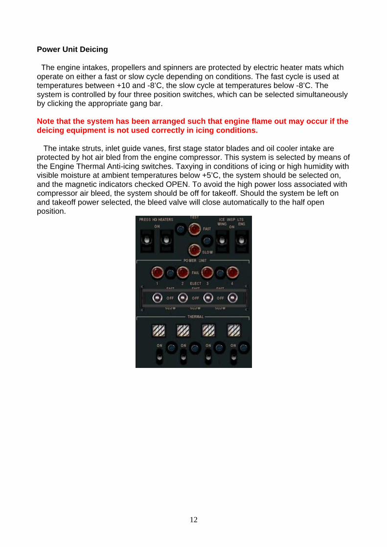
Power Unit Deicing The engine intakes, propellers and spinners are protected by electric heater mats which operate on either a fast or slow cycle depending on conditions. The fast cycle is used at temperatures between +10 and -8’C, the slow cycle at temperatures below -8’C. The system is controlled by four three position switches, which can be selected simultaneously by clicking the appropriate gang bar. Note that the system has been arranged such that engine flame out may occur if the deicing equipment is not used correctly in icing conditions. The intake struts, inlet guide vanes, first stage stator blades and oil cooler intake are protected by hot air bled from the engine compressor. This system is selected by means of the Engine Thermal Anti-icing switches. Taxying in conditions of icing or high humidity with visible moisture at ambient temperatures below +5’C, the system should be selected on, and the magnetic indicators checked OPEN. To avoid the high power loss associated with compressor air bleed, the system should be off for takeoff. Should the system be left on and takeoff power selected, the bleed valve will close automatically to the half open position.

13
VC9 V5 6. AIR CONDITIONING The air conditioning controls are located on the right overhead panel opened with the icon.
An engine driven compressor located in each inboard nacelle delivers air to the fuselage for cabin pressurisation and air conditioning. Spill valves allow any surplus compressor air to be exhausted to the atmosphere. The Spill valve are either manually or automatically controlled by the two Air Supply switches on the panel. The outflow is regulated by the pressure controller via six discharge valves. To the right of the engine instrument panel are cabin differential, height and rate of climb gauges. The upper knob on the cabin ROC gauge can be clicked to substitute the cabin pressure control. Prior to departure set the airfield QNH on the inner scale using the “B” knob. The outer scale and datum mark will rotate against the inner scale. Then set the airfield elevation using the large centre knob against the outer scale. The system will maintain the maximum differential and adjust cabin height accordingly. At the beginning of the descent set the destination airfield QNH and airfield elevation. Adjust for changes before arrival. After engine start the unpressurised flight valve is closed, the air supply switches set to AUTO, and the air switch switched ON. The air supply switches are returned to DECREASE before takeoff, before being reselected to AUTO in the climb. The air switch is switched off just before landing and the air supply switches set to decrease.
Maximum Operating Altitude 27000 ft
Maximum Cabin Differential Pressure 4.7 psi

14
VC9 V5 7. FLIGHT SYSTEM, RADIO INSTALLATION AND AUTOPILOT Radios The radio panel is accessed with the icon. The aircraft is fitted with dual Nav and Comm VHF radios and two ADF receivers.The mouse areas for the Nav/Comm radios are on the tuning knobs below the dialled frequency, those for the ADF sets are on the four tuning knobs on each set.
Flight System
Radio Selector. The radio selector is mounted on the main instrument panel and is used to select Nav1 or Nav2 information to the Flight System. The top switch is selected to 1 or 2 as desired. Note that the Azimuth Director and Pitch Director will only respond to Nav1 displacements so if Nav2 is selected the radial and glide path must be flown raw. When the switch is Off, the Azimuth Director will respond to differences between the Heading Pointer and Heading Index on the Beam Compass. A magnetic indicator above the airspeed indicator shows the input to the Flight System.
Director Horizon
1. Beam Flag. Visible when a steady VOR/Localiser signal is received 2. G/P Flag. Visible when a steady Glide Path signal is received. 3. Pitch Director. Shows demand for pitch corrections relative to GP deviation. 4. Horizon Bar. Moves relative to aircraft bank. 5. Pitch Pointer. Moves vertically relative to aircraft pitch 6. Pitch Scale. 7. Bank Scale. 8. Azimuth Director. Shows demand for heading and bank corrections. 9. Ring Sight. Placing the Ring Sight over the Azimuth Director will correctly bank the
aircraft. 10. Pitch Scale Setting Knob. Must be fully wound down for ILS glide path signals

15
Beam Compass 1. Sense Switch. Points up when flying towards a station and down when
flying from it. With the switch across, no signals are received. 2. Compass Scale. At its top datum, the Compass Scale shows the VOR or ILS course
selected on the Omni Bearing Indicator. Additionally it may be rotated using the area over the Compass Warning Light.
3. Heading Pointer. Shows aircraft heading relative to the Compass Scale. 4. Heading Index. Used to set desired heading 5. Beam Displacement Bar. Shows aircraft deviation from the selected course. 6. Beam Displacement Scale. 7. Setting Knob. Used to alter the Heading Index. 8. Compass Warning Lamp (Inoperative).
Omni Bearing Selector The Omni Bearing Selector is used to select the desired radial/localiser to the Flight System using the setting knob on the right. The switch on the left may be used to select the reciprocal bearing to that shown in the window. The bearing shown is that relative to the radio aid selected on the Radio Selector. A To/From indicator shows if the aircraft is flying to or from the station.
Course Deviation Indicator The CDI shows deviations from the course and glide path of a facility selected on the OPPOSITE Radio to that selected on the Radio Selector; i.e. if Nav1 is selected to the Flight System, Nav2 information will be displayed on the CDI and vice versa. It is recommended that for ILS approaches where a VOR bearing is not required, that the ILS be tuned to both radios. Radio Magnetic Indicator A twin pointer RMI is fitted, the red single pointer can show either VOR1 or ADF1, the green dual pointer VOR2 or ADF2. Switching is on the radio panel and two magnetic indicators beneath the RMI show the selection which has been made if a signal is received. Note the MI will show black if VOR is selected and an ILS frequency has been tuned, and the signal cannot be displayed on the RMI.

16
Autopilot Controller
The autopilot controller is on the radio panel on the pedestal, or an enlarged version can be opened with the icon. Before the autopilot can be used, the Power Master Switches on the pedestal should be switched on.
1. Power Switch. The Power switch must be pulled to initiate the supply to the Autopilot. This is effectively the FS Autopilot master. When the AP is ready for use the amber Ready lamp will illuminate.
2. Engage Button is pressed to engage the AP and hold the current pitch attitude. 3. Channel Switches . May be used to isolate the Rudder, Elevator or Aileron channels
from the Autopilot. 4. Airspeed/Height Lock. Turned to engage the airspeed or height lock. 5. Heading Hold Button. When engaged the aircraft may be steered by altering the
Heading Index on the Beam Compass. 6. Beam Coupling Switch. Pull to engage the FS Nav1 hold function. 7. Glide Coupling Switch. Pulled to engage FS Approach Hold function. This will also
cause the Beam Switch to engage. 8. Pitch Switch. Used to vary the nose up or down pitch after pressing the green
Engage button. 9. Turn Knob. Used to make manual turns using the autopilot. Heading hold must be
off. 10. Ready Lamp. The lamp will extinguish when any function is engaged.
An annunciator is fitted to the main instrument panel, and shows autopilot status. Note that the Autopilot will only respond to Nav1 information and that once the Power Switch is pulled , all Pitch/Azimuth Director indications are relative to AP commands.
17
VC9 V5 8. MINOR SYSTEMS Landing Lamps The switches for the wing mounted landing lamps and nose taxy lamp are located behind the undercarriage lever on the forward pedestal.
Max speed for operation of the landing lamps- 160kt IAS. Navigation & Beacon Lamps The Navigation lamps and anti collision beacons are controlled by switches on the overhead rear panel. The panel also houses the control switches for the cockpit lighting, heaters and passenger notices. Door Warning Indicator A red door warning annunciator is on the right overhead panel together with the starting controls. FL100 Warning Lamp A green warning lamp above the servo altimeter flashes when descending through FL100. To avoid nuisance when cruising at this level, the lamp can be pressed in. The system will automatically reset. Automated Checklists The automated checklists can be viewed with the icon. Clicking on the arrows of the checklist will move the pages forward or back. Speed Card and Trim Chart These can be viewed using the and icons. The Speed card also shows wind vector information, the crosswind component is calculated relative to the heading index setting on the beam compass. There are three Trim Charts for different power settings, and arrows on the charts can be clicked to change between them. Rapid Start Facility Clicking on the Rapid Start icon with the engines stopped (0 LP RPM) will perform the complete start sequence automatically.

18
VC9 V5 9. LIMITATIONS Airframe Limitations Manoeuvring Speed 204kt Vne 342kt, becoming 322kt at 17300ft, and 262kt at 27000ft Vno 305kt, becoming 281kt at 22000ft, and 252kt at 27000ft Engine Limitations TYNE 506 LP RPM MAX TGT ‘C TIME LIMIT Starting - 720 Momentary Ground Idling - 580 Unrestricted Approach Minimum 10500 580 Unrestricted Takeoff 15250 635 5 min Max Continuous 13500 615 Unrestricted Max Continuous 14500 775 Unrestricted Cruise Below……… 11100 565 Unrestricted Cruise 11100-12000 600 Unrestricted Cruise 12000-13500 615 Unrestricted Full Reverse 615 1 min Max Overspeed 16800 - 20 sec

19
VC9 V5 10. ENGINE AND FLIGHT HANDLING
Engine Starting Having completed the Captain’s checks:
1. Door Warning Lights.................................................................OUT 2. Anti Coll Lights............................................................................ON 3. Oil and Below FFP lights……………………...…..……….…ALL ON 4. Throttles....................................................................GROUND IDLE 5. HP Cocks.............................................................................CLOSED 6. Start Fuel Levers………………………………….……..….…..START 7. Start Fuel MI’s………………………………………………... …START 8. Fuel Temp O/Ride Switch (amb temp above 25’C)….DECREASE 9. Booster Pumps.............................................ALL ON, LAMPS OUT
10. Start Master............................................................................START 11. Engine 3 Starter Switch.........................................................START 12. Cycle Indicator and Igniter Lamps.............................. …….......ON 13. HP Cock………...500 LPRPM-MOVE TO INITIAL OPEN POSITION 14. Fuel Flow…………………………………………………………CHECK 15. TGT……………………………………………………………..MONITOR 16. Oil Pressure……………………………………....RISING, LAMP OUT 17. LP RPM …………………………………………………… ..2200 APPX 18. Cycle Indicator and Igniter Lamps………………………………OUT 19. REPEAT FOR ENGINES 4, 1 and 2 20. Start Fuel Levers………...3 & 4 OFF, TEMPS STABLE, 1 & 2 OFF 21. HP Cocks…………………………………………………………..100 % 22. LP RPM……………………………. …………...…..11250-11600 RPM 23. Start Master..............................................................................SAFE 24. Start Fuel MI’s………………………………………………….....NORM 25. Hyd Fail Lights…………………………………..………………….OUT 26. Hyd Pressures…………………………………….……….……CHECK 27. Fuel Pressure Lights……………………………………………….OUT 28. Fuel Trim…………………………………………………..SET FOR T/O 29. Oil Temps……………………………………………..….….ABOVE -15 30. External Master Switch………………………………….…………OFF 31. Battery Isolated Light……………………………………………...OUT 32. CWS …………………………………………...PRESS IN, LIGHT OUT
Taxying
After completion of the Before Taxy checks, open the gently to get the aircraft moving, minimum throttle movement is required to control the speed. All four engines should be used rather than increasing power on individual engines. Complete taxy checks. Set take off elevator trim, 0.5-2.0 divisions depending on weight, the checklist entry will show a tick when the elevator is correctly trimmed for takeoff.

20
Take-Off If there has been a change in OAT and/or ambient pressure between start up and take-off the Fuel Trimmers must be reset. When the Taxy and Before Take-Off checks have been completed and clearance received, enter the runway and return the throttles to idle. At the commencement of take-off , open the throttles smoothly to 10500 RPM, check the ground lever position lamp and below flight fine lights stay out. Open the throttle smoothly to full power and monitor RPM, torque,TGT, fuel flow, oil temperature and pressure. When safely airborne brake the wheels and retract the undercarriage. Once the undercarriage is locked up reduce power to max continuous, 13500 RPM and continue to acceleration height (Ha). Increase speed and select flaps to climb. At 1500ft QFE reduce power to climb power 12500 RPM. Retract flaps as required, but before exceeding 200kt. Cruise Complete Cruise Checks. Cruise power should be left at 12500 RPM, adjusting fuel trim to give as per the appropriate chart, and the airspeed allowed to build up. Normally cruising at FL180 the model will do about 250-260kt. Descent Allow sufficient time for descent; the cabin rate of descent is limited by the pressure
controller. Normally the average rate of descent should not exceed 1200-1600 ft/min from 25000 ft. which will result in a cabin rate of descent of 300-400 ft/min. Complete Descent Checks. The descent should be made with throttles at flight idle.
Approach Complete Approach checks. As the glide path bar on the CDI begins to travel towards the centre of the instrument, select flaps to Takeoff and undercarriage Down. There is a marked pitch up as the initial stages of flap are extended, requiring retrimming, further stages of flap cause little change in pitch. Once established select Approach flap Final Approach and Landing Established in the final, the fuel trim, should be set to a figure consistent with the conditions at the destination airfield, the figure having been extracted from the table as early as possible. At 1500ft the flaps can be extended to Land, and the speed reduced to Vat + 10-15kt, adjusting power as necessary to reach the threshold at Vat. On touchdown, the prop lever will move into the Ground position as the throttles are closed and ensure that the ground lever lamp and the below flight fine lamps all light. Lock the flight controls at about 70kt and complete the After Landing checks. Closing Down On stand apply the parking brake and check the throttles are closed. Allow the TGT’s to stabilise and close the HP Cocks. Return start fuel levers to Start. Turn off all the Booster Pumps and complete the Shutdown checks.

21
VC9 V5 Emergency Procedures Manual Feathering
Should the need arise to shut down an engine in flight:
1. HP Cock..............................................................TO FEATHER 2. Feathering Handle...........................................................PULL 3. LP Cock Switch and MI…………………………….……...SHUT 4. Throttle............................................................................OPEN 5. When Feathered, Alternator……...CHANGEOVER IF REQ’D 6. CWS…………………………………..…………………..CANCEL 7. Igniter…………………………..……………….…OFF IF IN USE 8. Wing De-Icing……OFF ON THAT SIDE IF OUTBOARD ENG. 9. PU Elect & Thermal De-Icing……..OFF AFFECTED ENGINE
10. If Failed Engine 3 or 4………………………………NO1 DC ON Unfeathering and Relighting in Flight
1. IAS……………………………………………….……...170kt MINIMUM 2. Flaps............................................................................UP OR CLIMB 3. Throttle ........................................................................FLIGHT IDLE 4. Booster Pumps.....................................................................ALL ON 5. Inter-engine & Crossfeed Cocks............................................SHUT 6. LP Cock Switch & MI…………………………..…………………OPEN 7. Oil Temperature………………………………………..……ABOVE -15 8. Relight Switch...............................................................................ON 9. HP Cock........................................................................FULLY OPEN 10. Feathering Handle................................................................PUSH IN 11. Throttle..............................OPEN SLOWLY TO REQUIRED POWER 12. TGT, Torque and Oil Pressure.................................. ............CHECK 13. Relight Switch...............................................................................OFF 14. Alternator Changeover.................................. ............AS REQUIRED 15. CWS..........................................................................................RESET 16. De-Icing…………………………………………………...AS REQUIRED
The information contained in this manual is based on Vanguard 951/953 data, around which Rick’s model has been constructed for use in Flight Simulator 2004. The information is for Flight Simulation use only and should not be considered for use with the real aircraft.
Fraser McKay, January 2008