vanguard applications ware:basic protocols:serial line ip (slip)
TRANSCRIPT

Vanguard Managed Solutions
Vanguard Applications Ware Basic Protocols
Serial Line IP (SLIP)

Notice
©2003 Vanguard Managed Solutions, LLC575 West StreetMansfield, Massachusetts 02048(508) 261-4000All rights reservedPrinted in U.S.A.
Restricted Rights Notification for U.S. Government Users
The software (including firmware) addressed in this manual is provided to the U.S. Government under agreement which grants the government the minimum “restricted rights” in the software, as defined in the Federal Acquisition Regulation (FAR) or the Defense Federal Acquisition Regulation Supplement (DFARS), whichever is applicable.
If the software is procured for use by the Department of Defense, the following legend applies:
Restricted Rights LegendUse, duplication, or disclosure by the Government
is subject to restrictions as set forth in subparagraph (c)(1)(ii) of the
Rights in Technical Data and Computer Software clause at DFARS 252.227-7013.
If the software is procured for use by any U.S. Government entity other than the Department of Defense, the following notice applies:
NoticeNotwithstanding any other lease or license agreement that may pertain to, or accompany the delivery of, this computer software, the rights of the Government regarding its use, reproduction, and disclosure are as set forth in FAR 52.227-19(C).
Unpublished - rights reserved under the copyright laws of the United States.

Notice (continued)
Proprietary Material
Information and software in this document are proprietary to Vanguard Managed Solutions (or its Suppliers) and without the express prior permission of an officer of VanguardMS, may not be copied, reproduced, disclosed to others, published, or used, in whole or in part, for any purpose other than that for which it is being made available. Use of software described in this document is subject to the terms and conditions of the Vanguard Managed Solutions Software License Agreement.
This document is for information purposes only and is subject to change without notice.
To comment on this manual, please send e-mail to [email protected]
Part No. T0106-06, Rev GPublication Code DSFirst Printing November 1998
Manual is current for Release 6.2 of Vanguard Applications Ware.


Serial Line IP
Overview
Introduction This manual describes Serial Line IP (SLIP) packet framing protocol available in the Vanguard Applications Ware, for use with Vanguard products. This manual supplements the Vanguard Configuration Basics Manual by describing additional features for SLIP support.
About the Serial Line IP
The Serial Line IP (SLIP) packet framing protocol defines a method of encapsulating IP packets for point-to-point serial connections running TCP/IP. The SLIP software feature connects X.25 and Frame Relay service to TCP/IP hosts, gateways, and routers that do not natively support any of these services yet can use serial lines.
SLIP is one of two standard mechanisms (the other is PPP) for transmitting TCP/IP packets over serial lines versus LAN lines. SLIP is a standard part of all TCP/IP packages and is quickly becoming a standard feature of various computer operating systems: SLIP has been a standard utility in UNIX, is a component of Windows 95/NT 4.0.
SLIP, defined by RFC 1055, allows small remote LANs and PCs access to router networks across an X.25 or Frame Relay (supported via RFC 1490 encapsulation) public or private network.
Related Documentation
You should also familiarize yourself with the Vanguard Configuration Basics Manual (Part Number T0113).
In This Manual Topic See Page
Features ......................................................................................................... 2Typical SLIP Applications ............................................................................ 4SLIP Configuration Sequence ...................................................................... 6Configuring the SLIP Port Record ............................................................... 7Configuring a PVC to FRI Bypass Station ................................................... 11Configuring a PVC to a Router Interface ..................................................... 12Configuring SLIP over X.25 Using PVCs ................................................... 13Configuring SLIP Using SVC ...................................................................... 14Statistics ........................................................................................................ 15
Serial Line IP 1

Features
Features
Introduction SLIP support on the 65xx and Vanguard platforms includes the following features:
• Support for RFC 1490 encapsulation of IP datagrams• 115 kbps asynchronous ports• Support for RFC 1055• Password-protected access to SLIP ports
Support for RFC 1490
A device connected to a SLIP port and a FRAD appears to a router as an RFC 1490 host.
A SLIP port can be configured to insert an RFC 1490 NLPID header into all packets forwarded to the adjacent channel (through the PVC connection) and strip the header from all packets arriving from the adjacent channel.
115 kbps Async Ports
A SLIP port supports 8 bit/no parity/1, 1.5, or 2 stop bits settings. Maximum port speed depends on the hardware platform:
• 38.4 kbps on the 6500PLUS
• 115 kbps on the 6520• 38.4 kbps on the Vanguard
Support for RFC 1055
SLIP on the Vanguard platforms adhere to RFC 1055, which defines two special characters:
• END (octal 300) • ESC (octal 333)
To send a packet, a SLIP host starts sending data in the packet. If a data byte is the same code as an END character, a two-byte sequence of ESC and octal 334 is sent instead.
If a data byte is the same as an ESC character, a two-byte sequence of ESC and octal 335 is sent instead. When the last byte in the packet has been sent, an END character is transmitted.
This SLIP implementation always throws away the zero-length IP packet. If noise exists on the line, data received due to the noise is discarded without effecting the following packet.
Password Protection
The SLIP port can optionally be configured for password protection using the standard Network User Identification database to configure and authenticate user accounts. After three unsuccessful attempts to log in, the SLIP port initiates EIA-level disconnection. For more detailed information, refer to the Vanguard Basics Manual.
How You Use SLIP You implement SLIP as another type of port on a Vanguard device. The SLIP port supports PVC-type connections to other protocol stacks, including X.25, Annex G, and Frame Relay Bypass.
The SLIP port also supports SVCs over X.25 and Annex G.
2 Serial Line IP

Features
SLIP Advantages SLIP offers the following advantages:
• It offers SLIP to TCP/IP using RFC 1490 Frame Relay encapsulation, as shown in Figure 1, which illustrates a network with remote PCs accessing an IP host off a router.
• Using SLIP port on a Vanguard product is an economical solution compared to buying an Ethernet Network Interface Card, an IP router, and an external DSU—then cabling it all together.
• There is no need to contend for Ethernet resources as found when dialing into a central site router supporting dial up access.
Figure 1. SLIP with RFC 1490
Limitations Because SLIP is merely a packet framing protocol, it only defines a sequence of characters that frame IP packets on a serial line. No addressing, packet type identification, or error detection/correction are provided.
X.25
SLIP
TCP/IPHost
Router
FRAD
FRAD
FRAD
FRADSLIP
SLIP
SLIP
Serial Line IP 3
T0106-06, Revision G Release 6.2

Typical SLIP Applications
Typical SLIP Applications
Introduction Using a Frame Relay Access Device (FRAD) with SLIP support lets users running remote TCP/IP applications connect over Frame Relay to headquarters LANs and/or WANs.
The FRAD links remote PCs, workstations, communications servers, and networks to a standard router that supports TCP/IP over Frame Relay (per RFC 1490).
The frame relay network concentrates all remote traffic into a single access line to the router, cutting carrier services and internetworking equipment costs.
SLIP Support Typical applications with SLIP support include:
• Single remote PC to a headquarters router• Small remote LAN to a headquarters router• Communication server to a headquarters router
Figure 2 illustrates typical applications for FRADs.
Figure 2. Typical SLIP Applications
Single Remote PC to a Headquarters Router
The link between the FRAD and the PC can be direct (NULL modem) or dialup. The FRAD supports a number of SLIP ports acting as a SLIP server. A multi-user system (for example, UNIX host) with dumb terminals is a variation of this.
DIRECT SLIP
DIALUP SLIP
Terminal
PC
PC
PC
Multi-UserSystem
DialupRouterTerminal
SLIP
SLIP
FRAD
FRAD
FRAD
FRAD
Router
Router
FrameRelay
Network
Terminal
CommServer
Terminal
SLIPFRAD
4 Serial Line IP

Typical SLIP Applications
Small Remote LAN to a Headquarters Router
An inexpensive dialup router or a general purpose computer (equipped with a Network Interface Card and a serial port) can act as an IP gateway.
Most low-end dialup routers and general purpose computers do not support frame relay interfaces; therefore, a FRAD could be a cost-effective alternative to upgrading to a more expensive router.
Communication Server to a Headquarters Router
Some communication servers support IP routing, integrating functionality of the terminal server and the router.
Serial Line IP 5
T0106-06, Revision G Release 6.2

SLIP Configuration Sequence
SLIP Configuration Sequence
Introduction This section describes procedures used to configure SLIP.
SLIP Configuration You can configure a SLIP port to support:
• PVC connections to X.25, Frame Relay Bypass, and Annex G protocol stacks. The SLIP port acts as a protocol converter, converting SLIP framing to RFC 1490 encapsulation.
• PVC connections to the IP router via a LAN connection table entry, which represents the IP router interface. The SLIP port is used as another interface on the router.
• SVC connections over X.25 and Annex G; the SLIP port can accept X.25 calls, but cannot originate calls.
6 Serial Line IP

Configuring the SLIP Port Record
Configuring the SLIP Port Record
Introduction This section describes how to navigate through the Control Terminal Port (CTP) Main menu and access the SLIP port record. Refer to the Vanguard Basics Manual for more detail about CTP procedures.
Configuring A SLIP Port
The following procedure describes how to configure a SLIP port.
Configure SLIP Port Menu
Figure 3 illustrates the SLIP port menu.
Figure 3. SLIP Port Record
Step Action Result
1 From the CTP Main menu, select Configure.
The Configure menu appears.
2 Select Port from the Configure menu.
The Port Configuration menu appears along with a prompt.
3 Enter the number of the port you want to configure.
Press Return. You are prompted to enter information for the port type.
4 Select SLIP as the port type. After you select SLIP as the port type, the SLIP parameters appear on the screen.
Node: Address: Date: Time:Menu: Configure Path: (Main.6)
NodePort
Port Name
*Port Number
Port Type
Connection Type
Flow Control
Port Speed
Stop Bits
Security
Encapsulation
Compression
FRA
PAD
FRIMUXSLIP
X.25
Null
(This feature is not yet supported.)
Serial Line IP 7
T0106-06, Revision G Release 6.2

Configuring the SLIP Port Record
Configuration Parameters
The following parameters make up the SLIP port record.
NoteUnless otherwise indicated, you must perform a port boot to implement a change to SLIP parameters.
Port Number:
Range: 1
Default: 1
Description: The number of the port to configure, which corresponds to the physical port position at the rear of the unit and constitutes the Port Record reference number.
Port Type:
Range: NULL, PAD, X25, FRI, FRA, SLIP
Default: SLIP
Description: Determines types of ports that can be selected and subsequent prompts that appear.
NoteA change to this parameter requires a node boot to take effect.
Connection Type:
Range: SIMP, DTR, DIMO
Default: SIMP
Description: Defines how EIA signalling should be handled by specifying the control signal handshake and clocking required for a connection to be made on this port.
• SIMP: simple; no control signals required.• DTR: dedicated; requires the data terminal ready (DTR)
signal.• DIMO: port handshakes with attached dial modem.
NoteFor a direct connect to a PC, DTR is recommended.
8 Serial Line IP

Configuring the SLIP Port Record
Flow Control:
Range: NONE, HARDWARE
Default: NONE
Description: Specifies the type of flow control:NONE: no flow control.HARDWARE: flow control using EIA signals.
NoteSLIP is not able to support XON/XOFF.
Port Speed:
Range: 50-38.4k
Default: 9600
Description: Specifies port speed in bits per second when using internal clocking.
NoteSpeed of 38.4 kbps can only be used on CPU+ cards.
Stop Bits:
Range: 1, 1.5, 2
Default: 1
Description: Specifies the number of stop bits:• 1: 1 stop bit• 1.5: 1.5 stop bits• 2: 2 stop bits
Security:
Range: NONE, PASS
Default: NONE
Description: Determines level of security by specifying access control to the port.
• NONE: no access control.• PASS: port is protected by the password (account name and
password configured in the NUI table).
Serial Line IP 9
T0106-06, Revision G Release 6.2

Configuring the SLIP Port Record
Encapsulation Type:
Range: NONE, RFC 1490
Default: NONE
Description: Determines whether an RFC 1490 header should be added by specifying the data encapsulation type.
10 Serial Line IP

Configuring a PVC to FRI Bypass Station
Configuring a PVC to FRI Bypass Station
Overview If you connect a SLIP port to FR Bypass, a PVC is required because FR Bypass only supports PVCs. No standard exists for supporting FR SVCs.
Configuration Perform the following steps to configure a PVC to FRI Bypass Station.
Step Action
1 Configure the SLIP Port; refer to “Configuring the SLIP Port Record” earlier in this document.
2 Configure the Node Record.
3 Configure the FRI port.
4 Configure the FRI station.
NoteThere are two types of stations: Annex G and Bypass. You can define a number of PVCs only for Annex G.
5 Configure the PVC Setup Table Source parameter as SLIP, port # (SLIP-#) and the Destination parameter as Frame Relay Bypass port #, station # (FRI-#S#). Refer to the X.25 Configuration Basics Manual for X.25 or the Frame Relay Option Manual for Frame Relay Bypass or Annex G concerning step-by-step details.
Serial Line IP 11
T0106-06, Revision G Release 6.2

Configuring a PVC to a Router Interface
Configuring a PVC to a Router Interface
Introduction Perform the following steps to configure a SLIP port to the IP router via a LAN connection table entry, which represents the IP router interface.
Configuration To configure a PVC to a router interface:
Step Action
1 Configure the SLIP Port; refer to “Configuring the SLIP Port Record.”
2 Configure the Node Record.
3 Connect a SLIP Port and a LAN Connection Table entry.
4 Configure the LAN Connection Table.
5 Configure the PVC Setup Table; refer to the Vanguard Basics Manual for step-by-step details.
12 Serial Line IP

Configuring SLIP over X.25 Using PVCs
Configuring SLIP over X.25 Using PVCs
Overview You can connect a SLIP Port to either X.25 or an Annex G channel using a PVC. When connecting a SLIP port to Annex G stations, X.25 SVCs can be established over an Annex G type of station, because essentially you have an X.25 stack over the FR stack.
Configuration Perform the following steps to configure SLIP over X.25 using PVCs.
Step Action
1 Configure the SLIP Port; refer to “Configuring the SLIP Port Record” earlier in this document.
2 Configure the Node Record.
3 Configure the FRI port and the FRI station.
NoteThe number of PVC channels parameter must be configured to reflect a value other than the default of 0Or:Configure an X.25 port.
4 Configure the PVC Setup Table. Refer to the X.25 Configuration Basics Manual for X.25 or the Frame Relay Option Manual for Frame Relay Bypass or Annex G concerning generic configuration procedures.
Serial Line IP 13
T0106-06, Revision G Release 6.2

Configuring SLIP Using SVC
Configuring SLIP Using SVC
Overview Perform the following procedures to connect a remote router to a SLIP port using SVC.
Guidelines Ensure that the remote node on the other side of the WAN is capable of an autocall. A SLIP port only accepts incoming calls; it does not initiate calls.
Refer to the Vanguard Basics Manual for generic configuration procedures.
Configuration Perform the following steps to configure SLIP using SVC.
Step Action
1 Configure the SLIP Port; refer to “Configuring the SLIP Port Record” earlier in this document.
2 Configure the Node Record.
3 Configure a LAN Connection table entry for autocalling.
4 Create a mnemonic that defines the address of a SLIP Port.
5 Configure the routing table on a remote node (router) to forward the call onto the proper channel (X.25 or Annex G).
14 Serial Line IP

Statistics
Statistics
Introduction This section describes the statistics used with SLIP. Other statistics are described in the Vanguard Basics Manual.
Accessing Detailed SLIP Port Statistics
Detailed SLIP port statistics provide status reports concerning various SLIP port operations. The following procedure describes how to view Detailed SLIP port statistics.
Typical SLIP Statistics Screens
The following figures present sample statistics screens that you may see for a SLIP port. Fields that appear on screen are similar to those in Figures 4 and 5, which reflect SLIP port status.
Step Action Result
1 From the CTP Main menu, select Status/Statistics.
Status/Statistics menu appears.
2 Select Detailed Port Statistics from the Status/Statistics menu.
A prompt appears.
3 Enter the number of the selected port you want statistics on.
Press Return. The Detailed Port Statistics screen for that port appears.
Serial Line IP 15
T0106-06, Revision G Release 6.2
Statistics
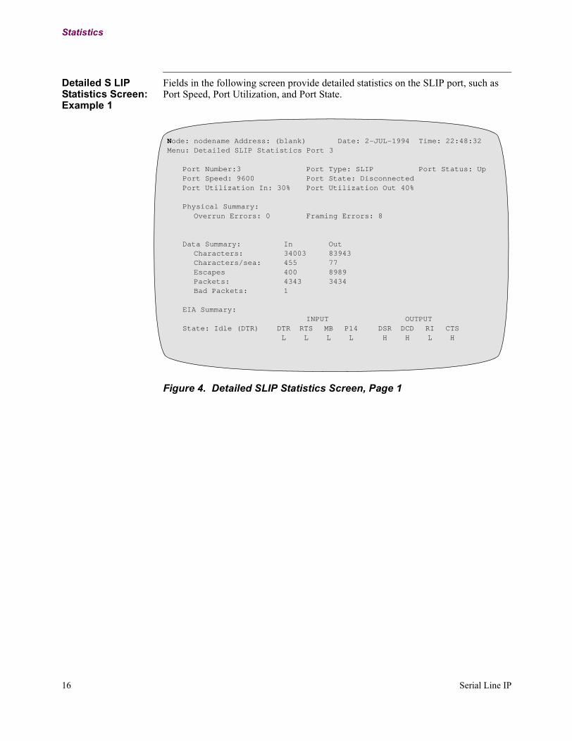
Detailed S LIP Statistics Screen: Example 1
Fields in the following screen provide detailed statistics on the SLIP port, such as Port Speed, Port Utilization, and Port State.
Figure 4. Detailed SLIP Statistics Screen, Page 1
Node: nodename Address: (blank) Date: 2-JUL-1994 Time: 22:48:32Menu: Detailed SLIP Statistics Port 3
Port Number:3 Port Type: SLIP Port Status: UpPort Speed: 9600 Port State: DisconnectedPort Utilization In: 30% Port Utilization Out 40%
Physical Summary:Overrun Errors: 0 Framing Errors: 8
Data Summary: In OutCharacters: 34003 83943Characters/sea: 455 77Escapes 400 8989Packets: 4343 3434Bad Packets: 1
EIA Summary:INPUT OUTPUT
State: Idle (DTR) DTR RTS MB P14 DSR DCD RI CTSL L L L H H L H
16 Serial Line IP

Statistics
Detailed SLIP Statistics Screen: Example 2
Fields in the following screen provide detailed statistics on the SLIP port, such as Call Summary information.
Figure 5. Detailed SLIP Statistics Screen, Page 2
Node: nodename Address: (blank) Date: 2-JUL-1994 Time: 22:50:32Menu: Detailed SLIP Statistics Port 3
Call Summary:
Connection Type: SVCEncapsulation Type: RFC 1490Connection State: Connected
Last Inbound Call:Calling Address: 10003Calling Address: 20094Facilities:CUD: C0010100
Serial Line IP 17
T0106-06, Revision G Release 6.2

Statistics
Detailed SLIP Port Statistics Terms
The following terms appear in the Detailed SLIP port statistics screens.
Term Description
Port Number: Indicates a specific port (physical port number) in the node.
Port Type: Indicates the type of access protocol for this port. This field displays SLIP, indicating that this port is accessed by the SLIP protocol.
Utilization In: Inbound utilization of the port.
Utilization Out: Outbound utilization of the port.
Port Status: Specifies current port status:• Up• Disabled• Busy Out
Port State: Specifies the current port state:• Disconnected• Login• Connected
Port Speed: Message transmission in bits per second.
Physical Summary: Specifies the number of overrun and framing errors since the last node reset.
Data Summary In: Specifies the number of bytes, SLIP escape characters, packets, and bad packets received on the port. A bad packet is one that contains SLIP protocol errors, which constitute incorrect escape sequences, or one that is shorter than 20 bytes, which is the legal limit for valid IP packets.
Data Summary Out: Specifies the number of bytes, SLIP escape characters, and packets sent over the port.
EIA Summary: Indicates the state of EIA control signals.
18 Serial Line IP

Index
Index-1
A
Applications 4
C
ConfiguringFRI to FRA using PVCs 11overview 6PVC to a router interface 12SLIP over X.25 using PVCs 13SLIP Port Record 7SLIP using SVC 14
D
Detailed SLIP Port Statisticsaccessing 15terms used in 18
P
Password protectiondescription 2
R
ReportsSLIP port 18
RFC 1055 2RFC 1490 2
S
Serial Line IPdefinition 1features 2function 2
SLIP portspeed 2
SLIP Port Menu 7SLIP Port Record Parameters 8