valves, controllers + systems double regulating and ... · measuring adapter 106 02 98 extension...
TRANSCRIPT
Valves, controllers + systemsDouble regulating and commissioning valves
”Hydrocontrol F” cast iron, PN 16Technical information
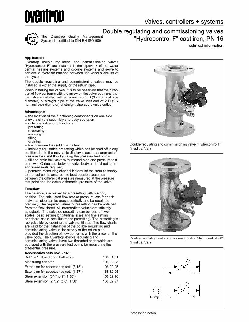
Double regulating and commissioning valve ”Hydrocontrol FR”(illustr. 2 1/2”)
Application:Oventrop double regulating and commissioning valves"Hydrocontrol F” are installed in the pipework of hot watercentral heating systems and cooling systems and serve toachieve a hydronic balance between the various circuits ofthe system.The double regulating and commissioning valves may beinstalled in either the supply or the return pipe.When installing the valves, it is to be observed that the direc-tion of flow conforms with the arrow on the valve body and thatthe valve is installed with a minimum of 3 D (3 x nominal pipediameter) of straight pipe at the valve inlet and of 2 D (2 xnominal pipe diameter) of straight pipe at the valve outlet.
Advantages:– the location of the functioning components on one sideallows a simple assembly and easy operation– only one valve for 5 functions: presetting measuring isolating filling draining– low pressure loss (oblique pattern)– infinitely adjustable presetting which can be read off in anyposition due to the moveable display, exact measurement ofpressure loss and flow by using the pressure test points– fill and drain ball valve with internal stop and pressure testpoint with O-ring seal between valve body and test point (noadditional seals required)– patented measuring channel led around the stem assemblyto the test points ensures the best possible accuracybetween the differential pressure measured at the pressuretest point and the actual differential pressure of the valve
Function:The balance is achieved by a presetting with memory position. The calculated flow rate or pressure loss for eachindividual pipe can be preset centrally and be regulatedprecisely. The required values of presetting can be obtainedfrom the flow charts. All intermediate values are infinitelyadjustable. The selected presetting can be read off twoscales (basic setting longitudinal scale and fine settingperipheral scale, see illustration presetting). The presetting isreproducible by opening the valve until stop. The flow chartsare valid for the installation of the double regulating andcommissioning valve in the supply or the return pipeprovided the direction of flow conforms with the arrow on thevalve body. The Oventrop double regulating andcommissioning valves have two threaded ports which areequipped with the pressure test points for measuring thedifferential pressure.Accessories sets 3/4” - 14”:Set 1 = 1 fill and drain ball valve 106 01 91Measuring adapter 106 02 98Extension for accessories sets (3.15”) 106 02 95Extension for accessories sets (1.57”) 168 82 95Stem extension (3/4” to 2”, 1.38”) 168 82 96Stem extension (2 1/2” to 6”, 1.38”) 168 82 97
Double regulating and commissioning valve ”Hydrocontrol F”(illustr. 2 1/2”)
The Oventrop Quality ManagementSystem is certified to DIN-EN-ISO 9001
Installation notes
Pump

Double regulating and commissioning valves3/4” – 2”Measuring technic “classic”
Tender specification:Oventrop double regulating and commissioning valves withsecured infinitely adjustable presetting controllable at anytime with the help of the flow limiting device. Lengths according to DIN EN 558-1 basic series 1(corresponds to ISO 5752 series 1)All functioning components on one level, pressure test pointand fill and drain ball valve interchangeable. PN 16Size Item no.3/4” 106 26 461” 106 26 471 1/4” 106 26 481 1/2” 106 26 492” 106 26 50“Hydrocontrol F”PN 16, 14°F to 302°F, PN 20 for cold waterRound flanges according to DIN EN 1092-2, PN 16(corresponds to ISO 7005-2, PN 16) PN 6, 14°F to 302°FRound flanges according to DIN EN 1092-2, PN 6(corresponds to ISO 7005-2, PN 6)ANSI 150, 14°F to 302°FHole circle of the flanged connection according to ANSI 150Valve body made of cast iron (GG 25 EN-GJL-250 DIN EN1561), bonnet, stem and disc made of bronze/dezincificationresistant brass. Disc with PTFE seal. Maintenance-free stemseal due to double EPDM O-ring. With type approval certifi-cate for shipbuilding (PN 16 and ANSI 150).
Presetting 3/4” – 2”:1. The value of presetting of the valve is adjusted by turning
the handwheel. a. The display of the basic setting is shown by the longitudinal scale together with the sliding indictor. Each turnof the handwheel is represented by a line on the longitudinalscale. b. The display of the fine setting is shown by the peripheral scale on the handwheel together with the marking.The subdivisions of the peripheral scalecorrespond to 1/10th of a turn of the handwheel.2. The set value of presetting can be limited by turning the
inner adjustment stem clockwise until it seats. This can bedone by using the long end of a 3 mm Allen key.
Visibility/readability of the setting scales:Depending on the installation position of the double regulatingand commissioning valve, an improvement of the visibili-ty/readability of the setting scales is obtained by twisting thescales. With the valve fully closed and the two setting scaleson “0”, remove cover plug, undo screw and with a light tugpull the handwheel from the valve stem. Next, without alteringthe presetting (still indicating “0”), adjust the position of thehandwheel so that the indicator window is clearly visible.Finally refit the handwheel to the valve stem, tighten thescrew and replace the cover plug.Protecting the presetting:The sealing wire, item no. 108 90 91, which is to be orderedseparately, may be fitted through the hole in the handwheeland a lead seal may be fitted.Locking the handwheel:The handwheel can be locked in any position (1/10th of aturn). To do so, the existing cover plug is replaced by thelocking set, item no. 106 01 80, which is to be ordered sepa-rately. In addition, the locked handwheel can be secured byuse of the sealing wire.
“Hydrocontrol F”
PN 16
Size L Hmax. d1 D K n x Ød
3/4” 5.91 4.65 2.76 4.13 12.95 0.16x0.55
1” 6.30 4.65 2.76 4.53 13.35 0.16x0.55
1 1/4” 7.09 5.35 2.76 5.51 3.94 0.16x0.75
1 1/2” 7.87 5.35 2.76 5.91 4.33 0.16x0.75
2” 9.06 5.71 2.76 6.50 4.92 0.16x0.75
Dimensions:
Handwheel
3 mm Allen key
KDN D
H
nxØd
d1
L
Basic setting scale(longitudinal scale)
Hole forsealing wire
Cover plug
Screw
Handwheel
Fine setting(peripheral scale)
MarkingSlidingindicator

Double regulating and commissioning valves 2 1/2” – 6”Measuring technic “classic”Tender specification:Oventrop double regulating and commissioning valves withsecured, infinitely adjustable presetting controllable at anytime with the help of the flow limiting device. Lengths accord-ing to DIN EN 558-1 basic series 1 (corresponds to ISO 5752series 1). All functioning components on one level, pressuretest point and fill and drain ball valve interchangeable.“Hydrocontrol F”
PN 16Size Item no.2 1/2” 106 26 513” 106 26 524” 106 26 535” 106 26 546” 106 26 55
PN 16, 14°F to 302°F, PN 20 for cold waterRound flanges according to DIN EN 1092-2, PN 16 (corre-sponds to ISO 7005-2, PN 16) PN 6, 14°F to 302°F Roundflanges according to DIN EN 1092-2, PN 6 (corresponds toISO 7005-2, PN 6) ANSI 150, 14°F to 302°F Hole circle of theflanged connection according to ANSI 150 Valve body madeof cast iron (GG 25 EN-GJL-250 DIN EN 1561), bonnet, discand stem made of bronze/dezincification resistant brass. Discwith PTFE seal. Maintenance-free stem seal due to doubleEPDM O-ring.
Presetting 2 1/2” – 6”:1. The value of presetting of the valve is adjusted by turning
the handwheel. a. The display of the basic setting is shown by the longitudinal scale together with the sliding indicator.Each turn of the handwheel is represented by a line on thelongitudinal scale. b. The display of the fine setting is shown by the peripheral scale on the handwheel together with themarking. The subdivisions of the peripheral scale correspondto 1/10th of a turn of the handwheel.2. The set value of presetting can be limited by turning the
inner adjustment stem clockwise until it seats. This can bedone by using the long end of a 4 mm Allen key.
Visibility/readability of the setting scales:Depending on the installation position of the double regulatingand commissioning valve, an improvement of the visibility/readability of the setting scales is obtained by twisting thescales. With the valve fully closed and the two setting scaleson “0”, remove cover plug, undo screw and with a light tugpull the handwheel from the valve stem. Next, without alteringthe presetting (still indicating “0”), adjust the position of thehandwheel so that the indicator window is clearly visible.Finally refit the handwheel to the valve stem, tighten thescrew and replace the cover plug.Protecting the setting:A sealing wire may be fitted through the hole in the hand-wheel and a lead seal may be fitted.Locking the handwheel:The handwheel can be locked in any position (1/10th of aturn). Fit the enclosed clip in the cut-out in the handwheelbelow the holes between the guides, making sure it locatesinto the sliding indicator (see sketch). The clip can now besealed as illustrated. It is essential that the sealing wire isfitted tightly.
Dimensions:
K
DN D
H
nxØd
d1
L
“Hydrocontrol F”
PN 16
Size L Hmax. d1 D K n x Ød
21/2” 11.4 7.4 4.33 7.28 5.71 0.16x0.75
3” 12.2 8.00 4.33 7.83 6.3 0.31x0.75
4” 13.8 9.45 6.3 8.66 7.09 0.31x0.75
5” 15.8 11.1 6.3 9.84 8.27 0.31x0.75
6” 18.9 11.2 6.3 11.2 9.45 0.31x0.91
Basic setting scale(longitudinal scale)
Hole forsealing wire
Hole forsealing wire
Cover plug
Screw
Handwheel
Fine setting scale(peripheral scale)Marking
Slidingindicator
Lead seal
Guide
Clip

Double regulating and commissioning valves8” – 14”Measuring technic “classic”
Tender specification:Oventrop double regulating and commissioning valves withsecured, infinitely adjustable presetting controllable at anytime with the help of the flow limiting device.Lengths according to DIN EN 558-1 basic series 1(corresponds to ISO 5752 series 1)All functioning components on one level, pressure test pointand fill and drain ball valve interchangeable.Size PN 16
Item no.8” 106 26 56
10” 106 26 5712” 106 26 5814” 106 26 59“Hydrocontrol F”PN 16, 14°F to 302°F, PN 20 for cold waterRound flanges according to DIN EN 1092-2, PN 16(corresponds to ISO 7005-2, PN 16) PN 6, 14°F to 302°F Round flanges according to DIN EN 1092-2, PN 6 (corre-sponds to ISO 7005-2, PN 6) ANSI 150, 14°F to 302°F Hole circle of the flanged connection according to ANSI 150Valve body (DN 200 – DN 300 made of cast iron GG 25,EN-GJL-250 DIN EN 1561; DN 350 made of nodular cast ironGGG50, EN-GJS-500-7 according to DIN EN 1563), bonnet(DN 200 – DN 300 made of nodular cast iron GGG 40, EN-GJS-400-15 according to DIN EN 1563; DN 350 made ofnodular cast iron GGG50, EN-GJS-500-7 according to DINEN 1563), bronze disc, stem made of dezincification resistantbrass. Disc with PTFE seal. Maintenance-free stem seal due todouble EPDM O-ring.
Presetting 8” – 14”:1. The value of presetting of the valve is adjusted by turning
the handwheel. a. The complete 12 turns of the handwheel are shown by
the outer display. b. 1/10th of a turn of the handwheel is shown by the outer
display.2. Remover cover plug by introducing a screwdriver in the
slot and gently prising it off.3. The set value of presetting can be limited by turning the
inner adjustment stem clockwise until it seats. This can bedone by using a 10 mm screwdriver.
4. Refit the cover plug.
Protecting the setting:A sealing wire may be fitted through the hole in the hand-wheel and a lead seal may be fitted.
Locking the handwheel:The handwheel can be locked in any position (1/10th of aturn) by removing the existing cover plug and replacing it witha special one. The sealing wire is then fitted through the holein the handwheel and a lead seal is fitted.
Display1/10th of a turn
Displaycomplete turns
Handwheel
Leadseal
Cover plug
Dimensions:
K
DN D
H
nxØd
d1
L
“Hydrocontrol F”
PN 16
Size L Hmax. d1 D K n x Ød
8” 23.6 18.4 11.8 13.4 11.6 0.47x0.91
10” 28.7 18.9 11.8 15.9 14.0 0.47x1.1
12” 33.5 20.3 11.8 18.1 16.1 0.47x1.1
14” 38.6 22.1 11.8 20.5 18.5 0.47x1.1

3/4”
1”
Zeta values related to the inner pipe diameter according to DIN 2448 (21 mm)
Zeta values related to the inner pipe diameter according to DIN 2448(24.8 mm)
Pre
ssur
e lo
ss ∆
p [p
si]
Pre
ssur
e lo
ss ∆
p [p
si]
Flow rate qm [gpm]
Flow rate qm [gpm]
Pre-setting Cv-values Zeta-values Pre-
setting Cv-values Zeta-values
Pre-setting Cv-values Zeta-values Pre-
setting Cv-values Zeta-values
Presetting
Presetting
0.250.500.75
1.01.11.21.31.41.51.61.71.81.92.02.12.22.32.42.52.62.72.82.93.03.13.23.33.43.53.63.73.83.9
4.04.14.24.34.44.54.64.74.84.9
0.130.260.380.490.560.600.640.690.730.780.810.870.92
0.971.011.061.101.151.211.261.301.351.401.451.511.571.641.711.791.871.982.082.202.332.452.582.712.832.953.083.213.343.47
25698642428551763135011501028893783693635553498451411375345317287267248231216199184171156144131120108978778706357534844413835
5.05.15.25.35.45.55.65.75.85.96.06.16.26.36.46.56.66.76.86.97.0
3.593.713.843.974.094.224.354.474.594.724.854.975.065.155.235.305.365.425.475.51
5.55
333129272524222120191817161615151514141414
0.250.500.751.01.11.21.31.41.51.61.71.81.92.02.12.22.32.42.52.62.72.82.93.03.13.23.33.43.53.63.73.83.94.04.14.24.34.44.54.64.74.84.9
5.515.705.906.096.306.516.746.987.217.47
3.864.014.164.304.474.634.804.975.145.33
2.722.842.943.063.173.293.413.523.633.74
1.551.661.781.902.012.132.262.372.492.60
0.590.971.26
232587851934229625822820218116114513212111010294878176706662585551474441383533312927252422211918171615
5.05.15.25.35.45.55.65.75.85.96.06.16.26.36.46.56.66.76.86.97.0
7.727.978.178.358.518.658.788.909.009.099.199.279.349.419.489.539.589.639.679.719.74
141312121111111010109.99.59.49.29.19.08.98.88.78.78.6
0.15
8
22.1
9
14.5
0.145
14.5
0.145
0.15
8
22.1
9
0.5 1 52 730.25 4
0.25 0.5 1 52 73 4

1 1/4”
1 1/2”
Zeta values related to the inner pipe diameter according to DIN 2448(32.8 mm)
Zeta values related to the inner pipe diameter according to DIN 2448(41.8 mm)
Pre
ssur
e lo
ss ∆
p [p
si]
Pre
ssur
e lo
ss ∆
p [p
si]
Flow rate qm [gpm]
Flow rate qm [gpm]
Pre-setting Cv-values Zeta-values
Pre-setting Cv-values Zeta-values
Pre-setting Cv-values Zeta-values Pre-
setting Cv-values Zeta-values
Presetting
Presetting
0.250.500.75
1.01.11.21.31.41.51.61.71.81.92.02.12.22.32.42.52.62.72.82.9
3.03.13.23.33.43.53.63.73.83.9
4.04.14.24.34.44.54.64.74.84.9
0.470.971.45
1156626861184
2.012.232.452.672.903.123.343.563.784.00
4.224.444.664.885.105.335.555.775.996.21
6.436.666.887.127.347.577.808.028.268.49
8.678.949.169.409.629.85
10.0810.3010.5310.76
618502416350298258225198175156
140127115105968881757065
61565349464441393735
33313028272625242322
5.05.15.25.35.45.55.65.75.85.9
6.06.16.26.36.46.56.66.76.86.9
7.07.17.27.37.47.57.67.77.87.9
8.08.18.28.38.48.58.68.78.88.9
9.09.19.29.39.49.59.69.79.89.9
10.0
10.9911.2611.5311.8012.0312.3312.5912.8513.1013.35
13.6013.9114.1914.4314.6714.9015.1215.3115.5015.69
15.8716.0216.1916.3516.4916.6316.7716.9117.0317.16
17.2817.4117.5617.6717.8017.9318.0618.1918.3118.44
18.5718.7018.8418.9519.0819.2219.3519.4819.6019.73
19.86
21201918171616151514
14131212121111111010
9.99.79.69.49.29.08.98.88.68.5
8.48.38.18.07.97.87.77.67.57.4
7.37.27.17.06.96.86.76.66.56.4
6.3
0.250.500.75
1.01.11.21.31.41.51.61.71.81.9
2.02.12.22.32.42.52.62.72.82.9
3.03.13.23.33.43.53.63.73.83.9
4.04.14.24.34.44.54.64.74.84.9
1.031.942.90
3.804.164.484.865.215.555.886.226.576.88
7.217.487.768.028.318.598.889.179.479.76
10.1010.3610.6610.9711.2711.5911.9212.2312.5612.90
13.2313.5713.9214.2714.6314.9915.3515.7216.0916.48
61621750
787
456381329279243215191171153139
127118110103958984787469
65615855524946444240
38363432312928272524
5.05.15.25.35.45.55.65.75.85.9
6.06.16.26.36.46.56.66.76.86.97.07.17.27.37.47.57.67.77.87.9
8.08.18.28.38.48.58.68.78.88.9
9.09.19.29.39.49.59.69.79.89.9
10.0
16.8717.3417.8118.3118.7719.3319.8820.4421.0121.62
22.2422.7123.1423.5523.9424.3024.6625.0025.2825.63
25.9326.2226.5026.7827.0527.2927.5627.8028.0328.27
28.5028.6528.8128.9529.1029.2629.4129.5529.6929.83
29.9730.1030.2330.3730.5030.6330.7630.8831.0131.13
31.26
23222120191817161514
13131212121111111010
9.89.69.49.29.08.98.78.58.48.3
8.18.07.97.97.87.77.67.67.57.4
7.37.37.27.27.17.07.06.96.96.8
6.8
14.5
0.145
14.5
0.145
0.17
4
75.2
9
0.39
6
117.
71
0.25 0.5 1 52 3 64 8 10
0.25 0.5 1 52 73 64 10
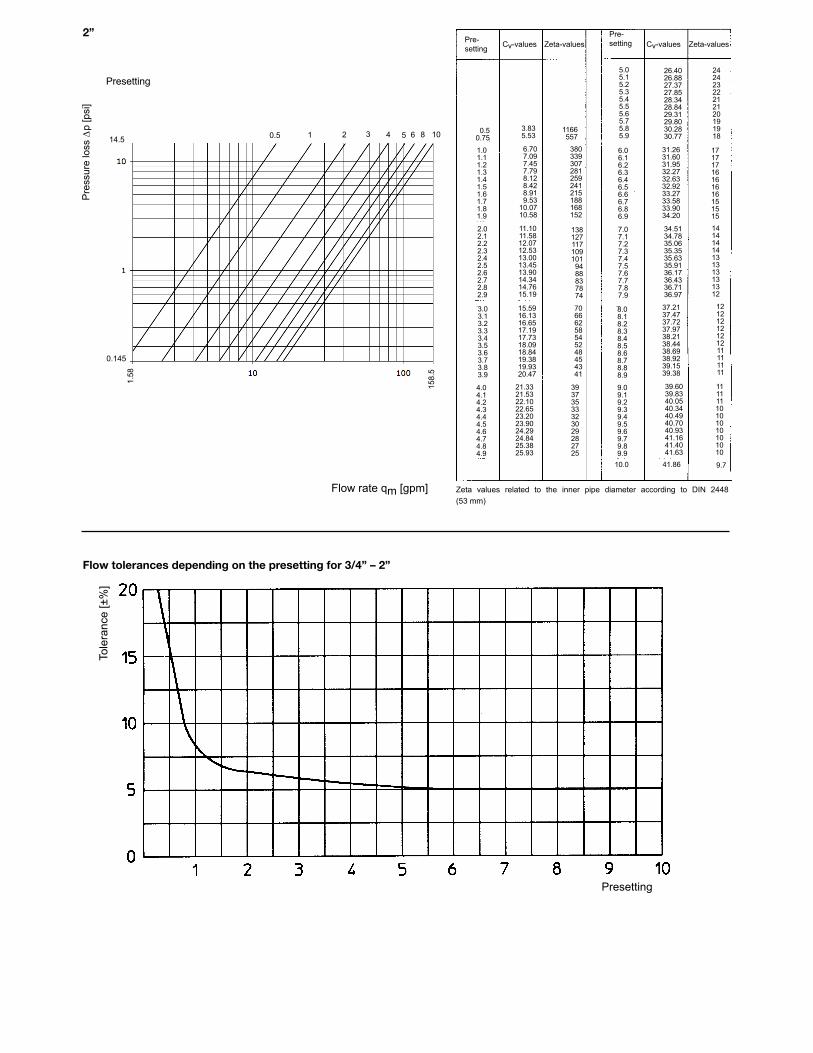
2”
Flow tolerances depending on the presetting for 3/4” – 2”
Pre
ssur
e lo
ss ∆
p [p
si]
Flow rate qm [gpm]
Presetting
Zeta values related to the inner pipe diameter according to DIN 2448 (53 mm)
Tole
ranc
e [±
%]
Pre-setting Cv-values Zeta-values
Pre-setting Cv-values Zeta-values
Presetting
0.50.75
3.835.53
1166557
1.01.11.21.31.41.51.61.71.81.9
2.02.12.22.32.42.52.62.72.82.9
3.03.13.23.33.43.53.63.73.83.9
4.04.14.24.34.44.54.64.74.84.9
21.3321.5322.1022.6523.2023.9024.2924.8425.3825.93
15.5916.1316.6517.1917.7318.0918.8419.3819.9320.47
11.1011.5812.0712.5313.0013.4513.9014.3414.7615.19
6.707.097.457.798.128.428.919.53
10.0710.58
380339307281259241215188168152
1381271171091019488837874
70666258545248454341
39373533323029282725
10.0 41.86 9.7
9.09.19.29.39.49.59.69.79.89.9
8.08.18.28.38.48.58.68.78.88.9
7.07.17.27.37.47.57.67.77.87.9
6.06.16.26.36.46.56.66.76.86.9
5.05.15.25.35.45.55.65.75.85.9
26.4026.8827.3727.8528.3428.8429.3129.8030.2830.77
31.2631.6031.9532.2732.6332.9233.2733.5833.9034.20
34.5134.7835.0635.3535.6335.9136.1736.4336.7136.97
37.2137.4737.7237.9738.2138.4438.6938.9239.1539.38
39.6039.8340.0540.3440.4940.7040.9341.1641.4041.63
11111110101010101010
12121212121211111111
14141414131313131312
17171716161616151515
2424232221212019191814.5
0.145
1.58
158.
5
0.5 1 52 3 64 8 10
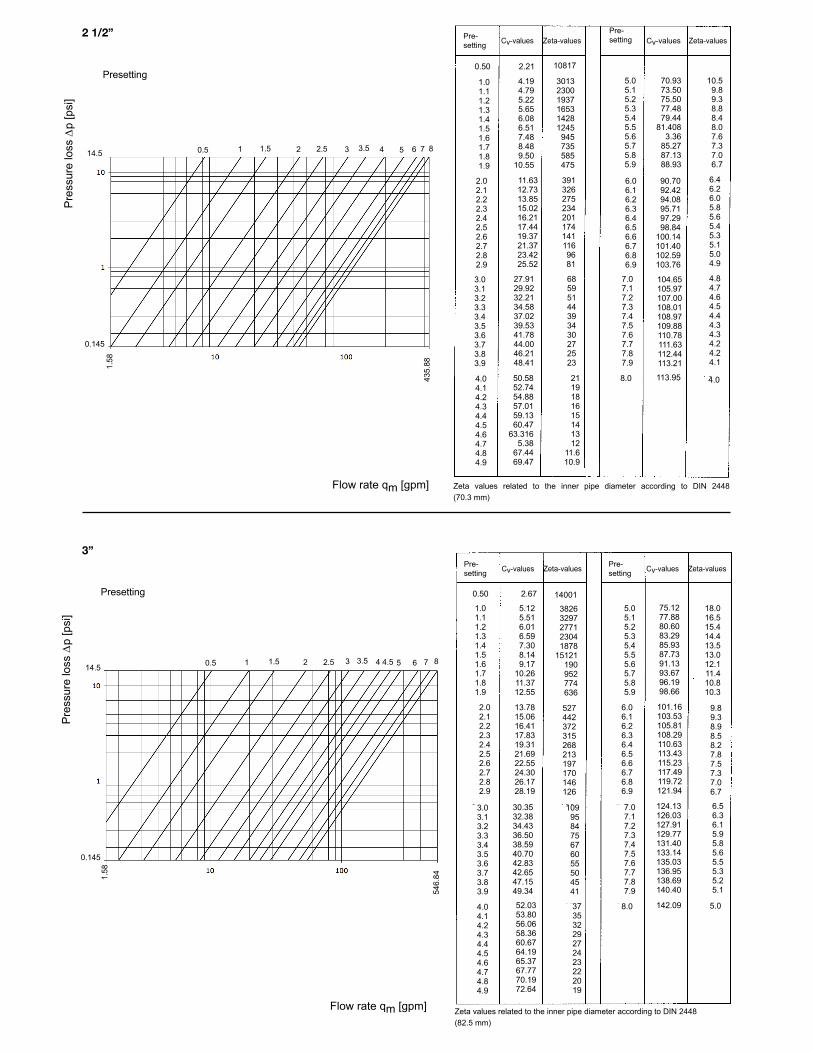
2 1/2”
3”
Zeta values related to the inner pipe diameter according to DIN 2448(70.3 mm)
Zeta values related to the inner pipe diameter according to DIN 2448(82.5 mm)
Pre
ssur
e lo
ss ∆
p [p
si]
Pre
ssur
e lo
ss ∆
p [p
si]
Flow rate qm [gpm]
Flow rate qm [gpm]
Pre-setting Cv-values Zeta-values
Pre-setting Cv-values Zeta-values
Pre-setting Cv-values Zeta-values Pre-
setting Cv-values Zeta-values
Presetting
Presetting
0.50
1.01.11.21.31.41.51.61.71.81.9
2.02.12.22.32.42.52.62.72.82.9
3.03.13.23.33.43.53.63.73.83.9
4.04.14.24.34.44.54.64.74.84.9
2.21 10817
4.194.795.225.656.086.517.488.489.50
10.55
11.6312.7313.8515.0216.2117.4419.3721.3723.4225.52
27.9129.9232.2134.5837.0239.5341.7844.0046.2148.41
50.5852.7454.8857.0159.1360.47
63.3165.38
67.4469.47
301323001937165314281245945735585475
3913262752342011741411169681
68595144393430272523
2119181615141312
11.610.9
5.05.15.25.35.45.55.65.75.85.9
6.06.16.26.36.46.56.66.76.86.9
7.07.17.27.37.47.57.67.77.87.9
8.0
70.9373.5075.5077.4879.44
81.4083.36
85.2787.1388.93
90.7092.4294.0895.7197.2998.84
100.14101.40102.59103.76
104.65105.97107.00108.01108.97109.88110.78111.63112.44113.21
113.95
10.59.89.38.88.48.07.67.37.06.7
6.46.26.05.85.65.45.35.15.04.9
4.84.74.64.54.44.34.34.24.24.1
4.0
0.50
2.02.12.22.32.42.52.62.72.82.9
3.03.13.23.33.43.53.63.73.83.9
4.04.14.24.34.44.54.64.74.84.9
2.67
5.125.516.016.597.308.149.17
10.2611.3712.55
13.7815.0616.4117.8319.3121.6922.5524.3026.1728.19
30.3532.3834.4336.5038.5940.7042.8342.6547.1549.34
52.0353.8056.0658.3660.6764.1965.3767.7770.1972.64
14001
38263297277123041878
15121190952774636
527442372315268213197170146126
109958475676055504541
37353229272423222019
5.05.15.25.35.45.55.65.75.85.9
6.06.16.26.36.46.56.66.76.86.9
7.07.17.27.37.47.57.67.77.87.9
8.0
75.1277.8880.6083.2985.9387.7391.1393.6796.1998.66
101.16103.53105.81108.29110.63113.43115.23117.49119.72121.94
124.13126.03127.91129.77131.40133.14135.03136.95138.69140.40
142.09
18.016.515.414.413.513.012.111.410.810.3
9.89.38.98.58.27.87.57.37.06.7
6.56.36.15.95.85.65.55.35.25.1
5.0
1.01.11.21.31.41.51.61.71.81.9
14.5
0.145
14.5
0.145
1.58
435.
8854
6.841.
58
0.5 1 52 73 641.5 2.5 3.5 4.5 8
0.5 1 52 73 641.5 2.5 3.5 8
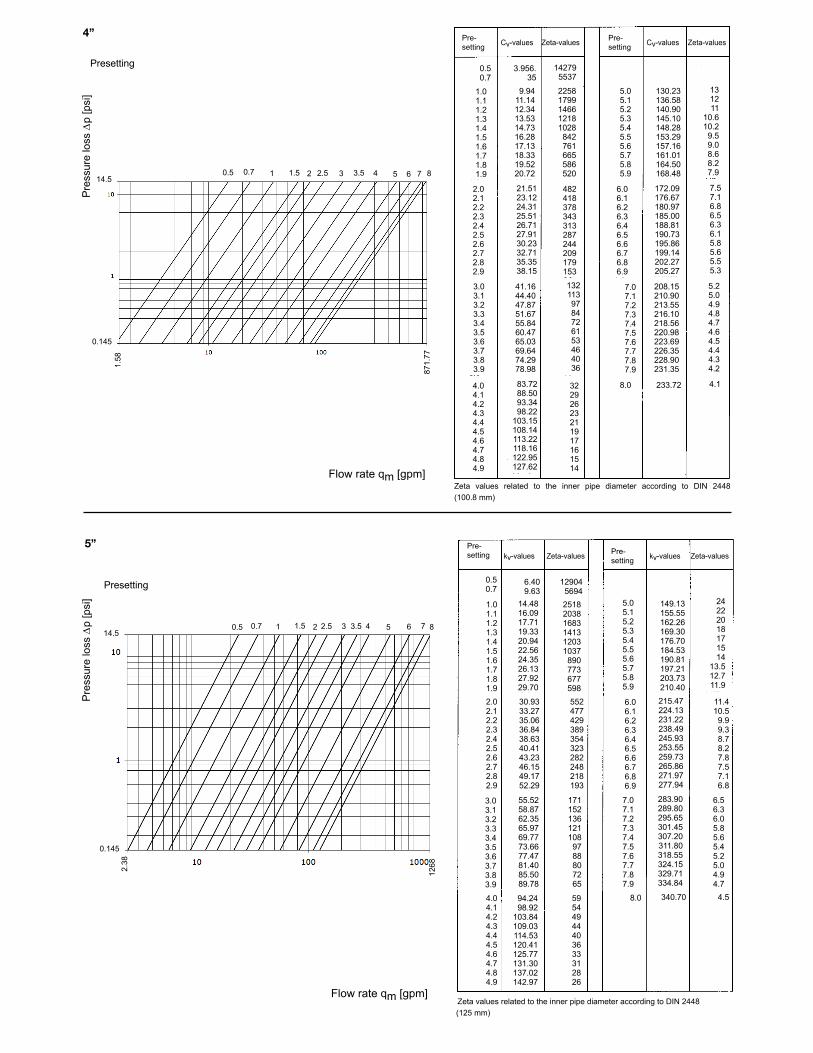
4”
5”
Zeta values related to the inner pipe diameter according to DIN 2448(100.8 mm)
Zeta values related to the inner pipe diameter according to DIN 2448(125 mm)
Pre
ssur
e lo
ss ∆
p [p
si]
Pre
ssur
e lo
ss ∆
p [p
si]
Flow rate qm [gpm]
Flow rate qm [gpm]
Pre-setting Cv-values Zeta-values Pre-
setting Cv-values Zeta-values
Pre-setting kv-values Zeta-values Pre-
setting kv-values Zeta-values
Presetting
Presetting
0.50.7
1.01.11.21.31.41.51.61.71.81.9
2.02.12.22.32.42.52.62.72.82.9
3.03.13.23.33.43.53.63.73.83.9
4.04.14.24.34.44.54.64.74.84.9
3.956.35
9.9411.1412.3413.5314.7316.2817.1318.3319.5220.72
21.5123.1224.3125.5126.7127.9130.2332.7135.3538.15
41.1644.4047.8751.6755.8460.4765.0369.6474.2978.98
83.7288.5093.3498.22
103.15108.14113.22118.16122.95127.62
142795537
22581799146612181028842761665586520
482418378343313287244209179153
1321139784726153464036
32292623211917161514
5.05.15.25.35.45.55.65.75.85.9
6.06.16.26.36.46.56.66.76.86.9
7.07.17.27.37.47.57.67.77.87.9
8.0
130.23136.58140.90145.10148.28153.29157.16161.01164.50168.48
172.09176.67180.97185.00188.81190.73195.86199.14202.27205.27
208.15210.90213.55216.10218.56220.98223.69226.35228.90231.35
233.72
131211
10.610.29.59.08.68.27.9
7.57.16.86.56.36.15.85.65.55.3
5.25.04.94.84.74.64.54.44.34.2
4.1
0.50.7
1.01.11.21.31.41.51.61.71.81.92.02.12.22.32.42.52.62.72.82.9
3.03.13.23.33.43.53.63.73.83.9
4.04.14.24.34.44.54.64.74.84.9
6.409.63
14.4816.0917.7119.3320.9422.5624.3526.1327.9229.70
30.9333.2735.0636.8438.6340.4143.2346.1549.1752.29
55.5258.8762.3565.9769.7773.6677.4781.4085.5089.78
283.90289.80295.65301.45307.20311.80318.55324.15329.71334.84
129045694251820381683141312031037890773677598552477429389354323282248218193
1711521361211089788807265
59544944403633312826
5.05.15.25.35.45.55.65.75.85.9
6.06.16.26.36.46.56.66.76.86.9
7.07.17.27.37.47.57.67.77.87.9
8.094.2498.92
103.84109.03114.53120.41125.77131.30137.02142.97
149.13155.55162.26169.30176.70184.53190.81197.21203.73210.40215.47224.13231.22238.49245.93253.55259.73265.86271.97277.94
340.70
24222018171514
13.512.711.9
11.410.59.99.38.78.27.87.57.16.8
6.56.36.05.85.65.45.25.04.94.7
4.5
14.5
0.145
14.5
0.145
1.58
871.
77
2.38
1268
0.5 0.7 1 52 73 641.5 2.5 3.5 8
0.5 0.7 1 52 73 641.5 2.5 3.5 8

6”
Flow tolerances depending on the presetting for 2 1/2”-6”
Zeta values related to the inner pipe diameter according to DIN 2448(150 mm)
Pre
ssur
e lo
ss ∆
p [p
si]
Flow rate qm [gpm]
Presetting
Tole
ranc
e [±
%]
Pre-setting Cv-values Zeta-values
Pre-setting Cv-values Zeta-values
Presetting0.50.7
1.01.11.21.31.41.51.61.71.81.92.02.12.22.32.42.52.62.72.82.9
3.03.13.23.33.43.53.63.73.83.9
4.04.14.24.34.44.54.64.74.84.9
6.0510.71
17.7020.0222.3624.6927.0229.3731.6734.3036.3438.6741.0043.1745.8349.1953.7862.7070.9379.7189.1299.30
110.49122.69133.08142.28150.60157.50165.36171.41178.29186.05
194.33202.88221.35219.83228.30236.80245.09253.24260.63269.14
2993495423494273021891796149912691091930829732651587521452378278218172138111
90736254484440373432
29272523212018171615
5.05.15.25.35.45.55.65.75.85.9
6.06.16.26.36.46.56.66.76.86.9
7.07.17.27.37.47.57.67.77.87.9
8.0
277.80284.56292.09299.53306.86316.74321.21328.26335.20342.06349.30355.53362.15368.70374.50379.88387.88393.42400.34406.47
413.49418.60424.49430.38436.22444.19447.72452.71458.37464.58
470.12
14.013.512.812.211.610.910.610.29.79.4
9.08.88.48.17.87.67.37.16.86.6
6.46.26.15.95.85.65.55.35.25.1
5.0
14.5
0.145
2.30
1585
0.5 0.7 1 52 73 641.5 2.53.5
8

8”
Pre
ssur
e lo
ss ∆
p [p
si]
Flow rate qm [gpm]
10”
Pre
ssur
e lo
ss ∆
p [p
si]
Flow rate qm [gpm]
Pre- kv-values Zeta-values Pre- kv-values Zeta-values setting setting
2.0 8.400 1318 7.0 682.0 14
2.1 72.5 1229 7.1 698.0 13 2.2 75.5 1133 7.2 714.0 13 2.3 79.0 1035 7.3 729.0 12 2.4 82.0 961 7.4 745.0 12 2.5 85.0 894 7.5 760.0 11 2.6 89.5 806 7.6 778.0 11 2.7 94.0 731 7.7 795.0 10 2.8 99.0 659 7.8 811.0 10 2.9 104.5 592 7.9 826.0 10 3.0 110.0 534 8.0 840.0 9 3.1 117.0 472 8.1 850.0 9 3.2 123.5 424 8.2 860.0 9 3.3 130.5 379 8.3 870.0 8 3.4 139.0 334 8.4 880.0 8 3.5 150.0 287 8.5 890.0 8 3.6 155.0 269 8.6 899.0 8 3.7 164.0 240 8.7 907.0 8 3.8 174.0 213 8.8 916.0 8 3.9 184.0 191 8.9 925.0 8 4.0 195.0 170 9.0 933.0 7 4.1 208.0 149 9.1 942.0 7 4.2 221.0 132 9.2 952.0 7 4.3 236.0 116 9.3 961.0 7 4.4 252.0 102 9.4 970.0 7 4.5 270.0 89 9.5 980.0 7 4.6 287.0 78 9.6 989.0 7 4.7 304.0 70 9.7 998.0 6 4.8 321.0 63 9.8 1008.0 6 4.9 338.0 57 9.9 1018.0 6 5.0 356.0 51 10.0 1028.0 6 5.1 373.0 46 10.1 1038.0 6 5.2 390.0 42 10.2 1048.0 6 5.3 407.0 39 10.3 1059.0 6 5.4 423.0 36 10.4 1071.0 6 5.5 440.0 33 10.5 1080.0 6 5.6 457.0 31 10.6 1088.0 5 5.7 473.0 29 10.7 1096.0 5 5.8 490.0 27 10.8 1104.0 5 5.9 506.0 25 10.9 1112.0 5 6.0 522.0 24 11.0 1120.0 5 6.1 539.0 22 11.1 1128.0 5 6.2 555.0 21 11.2 1136.0 5 6.3 571.0 20 11.3 1144.0 5 6.4 587.0 19 11.4 1152.0 5 6.5 607.0 18 11.5 1160.0 5 6.6 619.0 17 11.6 1168.0 5 6.7 635.0 16 11.7 1176.0 5 6.8 651.0 15 11.8 1184.0 5 6.9 666.0 15 11.9 1192.0 4
Pre-setting kv-values Zeta-values Pre-
setting kv-values Zeta-values
Zeta values related to the inner pipe diameter according to DIN 2448 (207.3mm)
Zeta values related to the inner pipe diameter according to DIN 2448 (254.4 mm)
2.02.12.22.32.42.52.62.72.82.9
3.03.13.23.33.43.53.63.73.83.9
4.04.14.24.34.44.54.64.74.84.95.05.15.25.35.45.55.65.75.85.9
6.06.16.26.36.46.56.66.76.86.9
56.8660.0063.0266.0569.0772.0977.2182.3387.4492.56
97.67104.65111.63118.60125.58132.56140.70149.77158.37166.98175.58188.37201.16213.95226.74239.53252.09264.65277.21289.77
302.67316.16330.00343.72357.56372.09386.05400.93415.81430.58
445.35460.47475.58490.70505.81555.58534.88549.42563.72578.14
11911070969883807741646568504449
404352309274244219195172154138
1251099584756761555046
41383533302826242221
19181716151413131212
7.07.17.27.37.47.57.67.77.87.9
8.08.18.28.38.48.58.68.78.88.9
9.09.19.29.39.49.59.69.79.89.9
10.010.110.210.310.410.510.610.710.810.9
11.011.111.211.311.411.511.611.711.811.912.0 947.09
918.60921.16923.84926.51929.19931.86934.88937.91940.93944.19
894.19896.74899.30901.86904.65906.98909.3091163
913.95916.28
842.44850.47858.37866.16874.07881.98884.42886.86889.30891.74
718.60728.84738.14737.44757.67767.44782.33796.74812.44827.44
592.44603.95615.47626.98638.49650.00663.95677.33690.93704.65
11111010999888
7777776666
6555555555
5555555555
5555444444
4
14.5
0.145
14.5
0.145
47.5
5
3566
.3
63.4
5230
.6
52 73 642.5 3.5 4.5 5.5 8 9 12
52 73 647.5
2.5 3.5 4.55.5 6.5
8 910
1112
Presetting
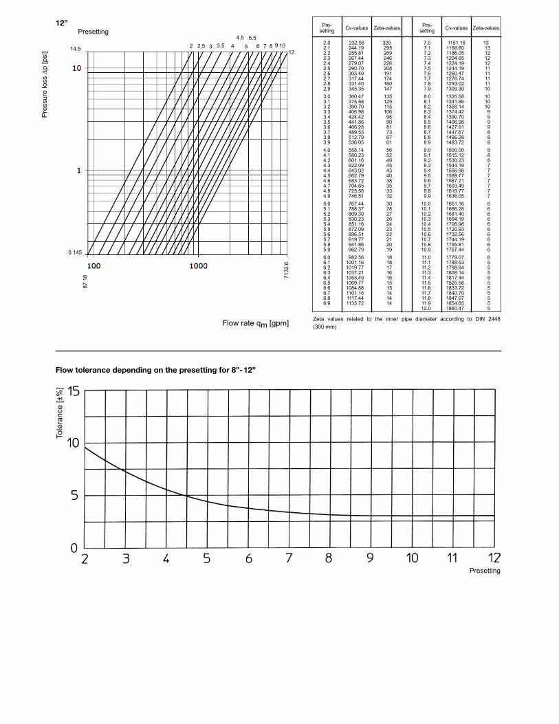
Flow tolerance depending on the presetting for 8”-12”
Presetting
Tole
ranc
e [±
%]
12”
Pre
ssur
e lo
ss ∆
p [p
si]
Flow rate qm [gpm]
Pre- Cv-values Zeta-values Pre- Cv-values Zeta-values setting setting
2.0 232.56 325 7.0 1151.16 13 2.1 244.19 295 7.1 1168.60 13 2.2 255.81 269 7.2 1186.05 12 2.3 267.44 246 7.3 1204.65 12 2.4 279.07 226 7.4 1224.19 12 2.5 290.70 208 7.5 1244.19 11 2.6 303.49 191 7.6 1260.47 11 2.7 317.44 174 7.7 1276.74 11 2.8 331.40 160 7.8 1293.02 11 2.9 345.35 147 7.9 1309.30 10 3.0 360.47 135 8.0 1325.58 10 3.1 375.58 125 8.1 1341.86 10 3.2 390.70 115 8.2 1358.14 10 3.3 406.98 106 8.3 1374.42 9 3.4 424.42 98 8.4 1390.70 9 3.5 441.86 90 8.5 1406.98 9 3.6 466.28 81 8.6 1427.91 9 3.7 489.53 73 8.7 1447.67 8 3.8 512.79 67 8.8 1466.28 8 3.9 536.05 61 8.9 1483.72 8 4.0 558.14 56 9.0 1500.00 8 4.1 580.23 52 9.1 1515.12 8 4.2 601.16 49 9.2 1530.23 8 4.3 622.09 45 9.3 1544.19 7 4.4 643.02 43 9.4 1556.98 7 4.5 662.79 40 9.5 1569.77 7 4.6 683.72 38 9.6 1587.21 7 4.7 704.65 35 9.7 1603.49 7 4.8 725.58 33 9.8 1619.77 7 4.9 746.51 32 9.9 1636.05 7 5.0 767.44 30 10.0 1651.16 6 5.1 788.37 28 10.1 1666.28 6 5.2 809.30 27 10.2 1681.40 6 5.3 830.23 26 10.3 1694.19 6 5.4 851.16 24 10.4 1706.98 6 5.5 872.09 23 10.5 1720.93 6 5.6 896.51 22 10.6 1732.56 6 5.7 919.77 21 10.7 1744.19 6 5.8 941.86 20 10.8 1755.81 6 5.9 962.79 19 10.9 1767.44 6 6.0 982.56 18 11.0 1779.07 6 6.1 1001.16 18 11.1 1789.53 5 6.2 1019.77 17 11.2 1798.84 5 6.3 1037.21 16 11.3 1808.14 5 6.4 1053.49 16 11.4 1817.44 5 6.5 1069.77 15 11.5 1825.58 5 6.6 1084.88 15 11.6 1833.72 5 6.7 1101.16 14 11.7 1840.70 5 6.8 1117.44 14 11.8 1847.67 5 6.9 1133.72 14 11.9 1854.65 5 12.0 1860.47 5
Zeta values related to the inner pipe diameter according to DIN 2448 (300 mm)
14.5
0.145
87.1
8 7132
.6
52 73 642.5 3.54.5 5.5
8 9 1012
Presetting
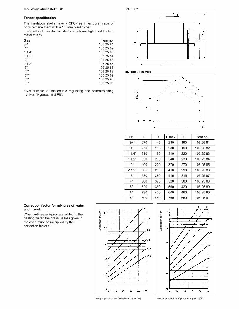
Insulation shells 3/4” – 8”
Tender specification:
The insulation shells have a CFC-free inner core made ofpolyurethane foam with a 1.5 mm plastic coat. It consists of two double shells which are tightened by twometal straps.
Size Item no.3/4” 106 25 811” 106 25 821 1/4” 106 25 831 1/2” 106 25 842” 106 25 852 1/2” 106 25 863” 106 25 874”* 106 25 885”* 106 25 896”* 106 25 908”* 106 25 91
* Not suitable for the double regulating and commissioningvalves “Hydrocontrol FS”.
Correction factor for mixtures of waterand glycol:
When antifreeze liquids are added to theheating water, the pressure loss given inthe chart must be multiplied by thecorrection factor f.
Weight proportion of ethylene glycol [%] Weight proportion of propylene glycol [%]
Cor
rect
ion
fact
or f
Cor
rect
ion
fact
or f
3/4” – 3”
DN 100 – DN 200
DN L D H max. H Item no.
13/4” 270 145 280 190 106 25 81
11” 270 155 280 190 106 25 82
11 1/4” 310 180 310 220 106 25 83
11 1/2” 330 200 340 230 106 25 84
12” 400 220 370 270 106 25 85
12 1/2” 505 260 410 290 106 25 86
13” 530 280 415 315 106 25 87
4” 580 320 520 380 106 25 88
5” 620 360 560 420 106 25 89
6” 730 400 600 460 106 25 90
8” 800 450 760 650 106 25 91
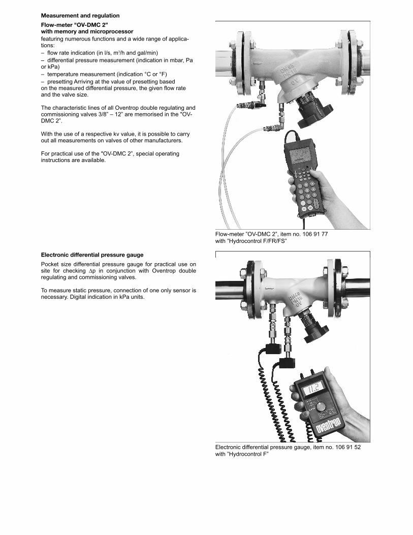
Measurement and regulation
Flow-meter "OV-DMC 2”with memory and microprocessorfeaturing numerous functions and a wide range of applica -tions: – flow rate indication (in l/s, m3/h and gal/min)– differential pressure measurement (indication in mbar, Paor kPa)– temperature measurement (indication °C or °F)– presetting Arriving at the value of presetting basedon the measured differential pressure, the given flow rateand the valve size.
The characteristic lines of all Oventrop double regulating andcommissioning valves 3/8” – 12” are memorised in the "OV-DMC 2”.
With the use of a respective kv value, it is possible to carryout all measurements on valves of other manufacturers.
For practical use of the "OV-DMC 2”, special operatinginstructions are available.
Electronic differential pressure gauge
Pocket size differential pressure gauge for practical use onsite for checking ∆p in conjunction with Oventrop doubleregulating and commissioning valves.
To measure static pressure, connection of one only sensor isnecessary. Digital indication in kPa units.
Flow-meter ”OV-DMC 2”, item no. 106 91 77with ”Hydrocontrol F/FR/FS”
Electronic differential pressure gauge, item no. 106 91 52with ”Hydrocontrol F”

Subject to technical modification without notice.
Product group 3 ti 83-1/10/MW Printed on paper free fromEdition 2007 chlorine bleaching.
Oventrop CorporationP.O. Box 78929 Kripes RoadEast Granby, CT 06026P:(860) 413-9173F:(860) 413-9436Email:[email protected]:www.oventrop-na.com